WO2024095367A1 - 加工シミュレーション装置、数値制御旋盤、工作機械システム、ワーク加工方法、および、プログラム - Google Patents
加工シミュレーション装置、数値制御旋盤、工作機械システム、ワーク加工方法、および、プログラム Download PDFInfo
- Publication number
- WO2024095367A1 WO2024095367A1 PCT/JP2022/040901 JP2022040901W WO2024095367A1 WO 2024095367 A1 WO2024095367 A1 WO 2024095367A1 JP 2022040901 W JP2022040901 W JP 2022040901W WO 2024095367 A1 WO2024095367 A1 WO 2024095367A1
- Authority
- WO
- WIPO (PCT)
- Prior art keywords
- model
- origin
- program
- machining
- workpiece
- Prior art date
- Legal status (The legal status is an assumption and is not a legal conclusion. Google has not performed a legal analysis and makes no representation as to the accuracy of the status listed.)
- Ceased
Links
Images


Classifications
-
- G—PHYSICS
- G05—CONTROLLING; REGULATING
- G05B—CONTROL OR REGULATING SYSTEMS IN GENERAL; FUNCTIONAL ELEMENTS OF SUCH SYSTEMS; MONITORING OR TESTING ARRANGEMENTS FOR SUCH SYSTEMS OR ELEMENTS
- G05B19/00—Program-control systems
- G05B19/02—Program-control systems electric
- G05B19/18—Numerical control [NC], i.e. automatically operating machines, in particular machine tools, e.g. in a manufacturing environment, so as to execute positioning, movement or co-ordinated operations by means of program data in numerical form
- G05B19/406—Numerical control [NC], i.e. automatically operating machines, in particular machine tools, e.g. in a manufacturing environment, so as to execute positioning, movement or co-ordinated operations by means of program data in numerical form characterised by monitoring or safety
- G05B19/4069—Simulating machining process on screen
-
- G—PHYSICS
- G05—CONTROLLING; REGULATING
- G05B—CONTROL OR REGULATING SYSTEMS IN GENERAL; FUNCTIONAL ELEMENTS OF SUCH SYSTEMS; MONITORING OR TESTING ARRANGEMENTS FOR SUCH SYSTEMS OR ELEMENTS
- G05B19/00—Program-control systems
- G05B19/02—Program-control systems electric
- G05B19/18—Numerical control [NC], i.e. automatically operating machines, in particular machine tools, e.g. in a manufacturing environment, so as to execute positioning, movement or co-ordinated operations by means of program data in numerical form
- G05B19/4093—Numerical control [NC], i.e. automatically operating machines, in particular machine tools, e.g. in a manufacturing environment, so as to execute positioning, movement or co-ordinated operations by means of program data in numerical form characterised by part programming, e.g. entry of geometrical information as taken from a technical drawing, combining this with machining and material information to obtain control information, named part program, for the NC machine
- G05B19/40931—Numerical control [NC], i.e. automatically operating machines, in particular machine tools, e.g. in a manufacturing environment, so as to execute positioning, movement or co-ordinated operations by means of program data in numerical form characterised by part programming, e.g. entry of geometrical information as taken from a technical drawing, combining this with machining and material information to obtain control information, named part program, for the NC machine concerning programming of geometry
-
- G—PHYSICS
- G05—CONTROLLING; REGULATING
- G05B—CONTROL OR REGULATING SYSTEMS IN GENERAL; FUNCTIONAL ELEMENTS OF SUCH SYSTEMS; MONITORING OR TESTING ARRANGEMENTS FOR SUCH SYSTEMS OR ELEMENTS
- G05B19/00—Program-control systems
- G05B19/02—Program-control systems electric
- G05B19/18—Numerical control [NC], i.e. automatically operating machines, in particular machine tools, e.g. in a manufacturing environment, so as to execute positioning, movement or co-ordinated operations by means of program data in numerical form
- G05B19/4093—Numerical control [NC], i.e. automatically operating machines, in particular machine tools, e.g. in a manufacturing environment, so as to execute positioning, movement or co-ordinated operations by means of program data in numerical form characterised by part programming, e.g. entry of geometrical information as taken from a technical drawing, combining this with machining and material information to obtain control information, named part program, for the NC machine
- G05B19/40937—Numerical control [NC], i.e. automatically operating machines, in particular machine tools, e.g. in a manufacturing environment, so as to execute positioning, movement or co-ordinated operations by means of program data in numerical form characterised by part programming, e.g. entry of geometrical information as taken from a technical drawing, combining this with machining and material information to obtain control information, named part program, for the NC machine concerning programming of machining or material parameters, pocket machining
-
- G—PHYSICS
- G05—CONTROLLING; REGULATING
- G05B—CONTROL OR REGULATING SYSTEMS IN GENERAL; FUNCTIONAL ELEMENTS OF SUCH SYSTEMS; MONITORING OR TESTING ARRANGEMENTS FOR SUCH SYSTEMS OR ELEMENTS
- G05B19/00—Program-control systems
- G05B19/02—Program-control systems electric
- G05B19/18—Numerical control [NC], i.e. automatically operating machines, in particular machine tools, e.g. in a manufacturing environment, so as to execute positioning, movement or co-ordinated operations by means of program data in numerical form
- G05B19/4097—Numerical control [NC], i.e. automatically operating machines, in particular machine tools, e.g. in a manufacturing environment, so as to execute positioning, movement or co-ordinated operations by means of program data in numerical form characterised by using design data to control NC machines, e.g. CAD/CAM
-
- B—PERFORMING OPERATIONS; TRANSPORTING
- B23—MACHINE TOOLS; METAL-WORKING NOT OTHERWISE PROVIDED FOR
- B23B—TURNING; BORING
- B23B1/00—Methods for turning or working essentially requiring the use of turning-machines; Use of auxiliary equipment in connection with such methods
-
- B—PERFORMING OPERATIONS; TRANSPORTING
- B23—MACHINE TOOLS; METAL-WORKING NOT OTHERWISE PROVIDED FOR
- B23B—TURNING; BORING
- B23B7/00—Automatic or semi-automatic turning-machines with a single working-spindle, e.g. controlled by cams; Equipment therefor; Features common to automatic and semi-automatic turning-machines with one or more working-spindles
- B23B7/12—Automatic or semi-automatic machines for turning of workpieces
-
- G—PHYSICS
- G05—CONTROLLING; REGULATING
- G05B—CONTROL OR REGULATING SYSTEMS IN GENERAL; FUNCTIONAL ELEMENTS OF SUCH SYSTEMS; MONITORING OR TESTING ARRANGEMENTS FOR SUCH SYSTEMS OR ELEMENTS
- G05B2219/00—Program-control systems
- G05B2219/30—Nc systems
- G05B2219/35—Nc in input of data, input till input file format
- G05B2219/35346—VMMC: virtual machining measuring cell simulate machining process with modeled errors, error prediction
-
- G—PHYSICS
- G05—CONTROLLING; REGULATING
- G05B—CONTROL OR REGULATING SYSTEMS IN GENERAL; FUNCTIONAL ELEMENTS OF SUCH SYSTEMS; MONITORING OR TESTING ARRANGEMENTS FOR SUCH SYSTEMS OR ELEMENTS
- G05B2219/00—Program-control systems
- G05B2219/30—Nc systems
- G05B2219/36—Nc in input of data, input key till input tape
- G05B2219/36204—Lathe, turning
-
- G—PHYSICS
- G05—CONTROLLING; REGULATING
- G05B—CONTROL OR REGULATING SYSTEMS IN GENERAL; FUNCTIONAL ELEMENTS OF SUCH SYSTEMS; MONITORING OR TESTING ARRANGEMENTS FOR SUCH SYSTEMS OR ELEMENTS
- G05B2219/00—Program-control systems
- G05B2219/30—Nc systems
- G05B2219/40—Robotics, robotics mapping to robotics vision
- G05B2219/40091—Tele-programming by graphical simulation
-
- G—PHYSICS
- G05—CONTROLLING; REGULATING
- G05B—CONTROL OR REGULATING SYSTEMS IN GENERAL; FUNCTIONAL ELEMENTS OF SUCH SYSTEMS; MONITORING OR TESTING ARRANGEMENTS FOR SUCH SYSTEMS OR ELEMENTS
- G05B2219/00—Program-control systems
- G05B2219/30—Nc systems
- G05B2219/45—Nc applications
- G05B2219/45136—Turning, lathe
Definitions
- the present invention relates to a machining simulation device, a numerically controlled lathe, a machine tool system, a workpiece machining method, and a program.
- Patent Document 1 discloses a machining simulation device.
- the machining simulation device described in Patent Document 1 comprises machining simulation means for simulating the relative motion of the tool and workpiece based on a machining program, a memory for storing three-dimensional models of the tool and workpiece together with their identifiers, a means for reading the identifier of the three-dimensional model specified in the machining program, and a means for calling from the memory a three-dimensional model having an identifier matching the read identifier and setting it in the machining simulation means.
- the object of the present invention is to provide a machining simulation device, a numerically controlled lathe, a machine tool system, a workpiece machining method, and a program that can accurately set the program origin on the machining simulation coordinate system.
- the machining simulation device includes a calculation device that sets the position of a program origin, which is the origin on the machining simulation coordinate system, based on a machine model origin on the machining simulation coordinate system corresponding to the machine origin of a numerically controlled lathe, a claw model that is a shape model of a claw attached to a chuck of the numerically controlled lathe, and a workpiece model that is a shape model of a workpiece gripped by the multiple claws, and performs a machining simulation to virtually machine the workpiece model by executing a machining program using the program origin as a reference position, and a communication circuit that transmits data indicating the position of the program origin to the numerically controlled lathe.
- the numerically controlled lathe includes a second communication circuit that receives data indicating the position of the program origin from a machining simulation device that performs a machining simulation to virtually machine the workpiece model by setting the position of a program origin, which is the origin on the machining simulation coordinate system, based on a machine model origin on the machining simulation coordinate system corresponding to the machine origin of the numerically controlled lathe, a claw model that is a shape model of the claws attached to the chuck of the numerically controlled lathe, and a workpiece model that is a shape model of the workpiece gripped by the multiple claws, and executing a machining program using the program origin as a reference position; a second memory that stores the machining program; the chuck, the multiple claws that are attached to the chuck and grip the workpiece, a spindle that supports the chuck, a rotary drive device that rotates the spindle around a first axis, a moving device that moves a first tool; and a second calculation device that sets the
- the machine tool system includes the above-mentioned machining simulation device and the above-mentioned numerically controlled lathe.
- the workpiece machining method includes the steps of: setting the position of a program origin, which is the origin on the machining simulation coordinate system, based on a machine model origin on a machining simulation coordinate system corresponding to the machine origin of a numerically controlled lathe, a claw model, which is a shape model of a claw attached to a chuck of the numerically controlled lathe, and a workpiece model, which is a shape model of a workpiece gripped by a plurality of the claws; performing a machining simulation in which the workpiece model is virtually machined by executing a machining program using the program origin as a reference position; setting the position of the machining program origin in the machining program coordinate system based on the position of the program origin; and machining the workpiece by the numerically controlled lathe that executes the machining program using the machining program origin as a reference position.
- the program is a program for causing a machining simulation device to execute a machining simulation method including the steps of: setting the position of a program origin, which is the origin on a machining simulation coordinate system, based on a machine model origin on the machining simulation coordinate system corresponding to the machine origin of a numerically controlled lathe, a claw model, which is a shape model of a claw attached to a chuck of the numerically controlled lathe, and a workpiece model, which is a shape model of a workpiece gripped by a plurality of the claws; performing a machining simulation in which the workpiece model is virtually machined by executing a machining program using the program origin as a reference position; and transmitting data indicating the position of the program origin to the numerically controlled lathe.
- the present invention provides a machining simulation device, a numerically controlled lathe, a machine tool system, a workpiece machining method, and a program that can accurately set the program origin on the machining simulation coordinate system.
- FIG. 1 is a block diagram showing an example of a hardware configuration of a machining simulation device according to a first embodiment.
- FIG. 2 is a functional block diagram of the arithmetic unit.
- FIG. 3 is a diagram showing a schematic diagram of the position of the machine origin in a numerically controlled lathe.
- FIG. 4 is a diagram showing a schematic diagram of the positional relationship between the machine model origin and the program origin in the machining simulation coordinate system.
- FIG. 5 is a diagram showing a schematic diagram of the positional relationship between the machine model origin and the program origin in the machining simulation coordinate system.
- FIG. 6 is a diagram showing a schematic view of a simulation image displayed on a display device.
- FIG. 7 is a diagram showing a schematic view of a simulation image displayed on a display device.
- FIG. 8 is a schematic perspective view showing the numerically controlled lathe according to the first embodiment.
- FIG. 9 is a block diagram showing an example of a hardware configuration of a control unit of a numerically controlled lathe.
- FIG. 10 is a diagram showing a schematic diagram of the positional relationship between the machine origin and the machining program origin in the machining program coordinate system.
- FIG. 11 is a block diagram showing an example of a hardware configuration of a control unit of a numerically controlled lathe.
- FIG. 12 is a diagram showing a schematic view of the offset amount displayed on the display device.
- FIG. 13 is a diagram showing a schematic view of a nail model setting window displayed on the display device.
- FIG. 14 is a diagram showing a schematic view of a workpiece model setting window displayed on the display device.
- FIG. 15 is a diagram showing a schematic view of a workpiece model creation window displayed on the display device.
- FIG. 16 is a diagram showing a typical state in which a chuck model setting window is displayed on the display device.
- FIG. 17 is a diagram that illustrates a schematic view of an assembly model in which a chuck model, a jaw model, and a workpiece model are combined and displayed on a display device.
- FIG. 18 is a diagram showing a schematic diagram of the positional relationship between the machine model origin and the program origin in the machining simulation coordinate system.
- FIG. 19 is a diagram showing a schematic diagram of the positional relationship between the machine model origin and the program origin in the machining simulation coordinate system.
- FIG. 20 is a diagram illustrating a schematic view of the second offset amount being displayed on the second display device.
- FIG. 21 is a diagram showing a schematic view of the first default data specifying the shape of the nail being displayed in an editable format on the second display device.
- FIG. 22 is a diagram typically showing a state in which a message recommending execution of the machining simulation again is displayed on the second display device.
- FIG. 23 is a diagram showing a schematic view of the second default data specifying the shape of the workpiece being displayed in an editable format on the second display device.
- FIG. 24 is a diagram typically showing a state in which a message recommending execution of the machining simulation again is displayed on the second display device.
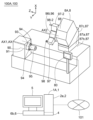
- FIG. 25 is a diagram illustrating a machine tool system according to the first embodiment.
- FIG. 21 is a diagram showing a schematic view of the first default data specifying the shape of the nail being displayed in an editable format on the second display device.
- FIG. 22 is a diagram typically showing a state in which
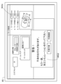
- FIG. 26 is a flowchart illustrating an example of a processing simulation method according to the first embodiment.
- FIG. 27 is a flowchart showing an example of a workpiece machining method in the first embodiment.
- FIG. 28 is a diagram illustrating an example of a non-volatile storage medium on which a program is recorded.
- machining simulation device 1 numerically controlled lathe 8
- machine tool system 100 machining simulation method, workpiece machining method, and program (more specifically, calculation program 41) in the embodiment will be described with reference to the drawings. Note that in the following description of the embodiment, parts and components having the same functions are given the same reference numerals, and repeated descriptions of parts and components given the same reference numerals will be omitted.
- FIG. 1 is a block diagram showing an example of a hardware configuration of the machining simulation device 1A in the first embodiment.
- FIG. 2 is a functional block diagram of a calculation device 2.
- FIG. 3 is a diagram showing a schematic view of a position of a machine origin G0 in a numerically controlled lathe.
- FIGS. 4 and 5 are diagrams showing a schematic view of a positional relationship between a machine model origin F0 and a program origin F1 in a machining simulation coordinate system.
- FIGS. 1 is a block diagram showing an example of a hardware configuration of the machining simulation device 1A in the first embodiment.
- FIG. 2 is a functional block diagram of a calculation device 2.
- FIG. 3 is a diagram showing a schematic view of a position of a machine origin G0 in a numerically controlled lathe.
- FIGS. 4 and 5 are diagrams showing a schematic view of a positional relationship between a machine model origin F0 and a program origin F1 in a machining simulation coordinate system
- FIG. 6 and 7 are diagrams showing a state in which a simulation image 50A is displayed on a display device 5.
- FIG. 8 is a schematic perspective view showing a numerically controlled lathe 8A in the first embodiment.
- FIG. 9 is a block diagram showing an example of a hardware configuration of a control unit 80 of the numerically controlled lathe 8A.
- FIG. 10 is a diagram showing a schematic view of a positional relationship between a machine origin G0 and a machining program origin G1 in a machining program coordinate system.
- FIG. 11 is a block diagram showing an example of a hardware configuration of a control unit 80 of the numerically controlled lathe 8A.
- FIG. 12 is a diagram showing a state where the offset amount T1 is displayed on the display device 5.
- FIG. 13 is a diagram showing a state where the setting window 50B of the claw model 94m is displayed on the display device 5.
- FIG. 14 is a diagram showing a state where the setting window 50C of the workpiece model 95m is displayed on the display device 5.
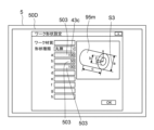
- FIG. 15 is a diagram showing a state where the workpiece model creation window 50D is displayed on the display device 5.
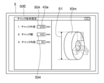
- FIG. 16 is a diagram showing a state where the setting window 50E of the chuck model 93m is displayed on the display device 5.
- FIG. 17 is a diagram showing a state where the assembly model 92m in which the chuck model 93m, the claw model 94m, and the workpiece model 95m are combined is displayed on the display device 5.
- FIG. 18 and 19 are diagrams showing a positional relationship between the machine model origin F0 and the program origin F1 in the machining simulation coordinate system.
- FIG. 20 is a diagram showing a state where the second offset amount T2 is displayed on the second display device 85.
- Fig. 21 is a diagram showing a state where the first default data DD1 specifying the shape of the claw 94 is displayed in an editable format on the second display device 85.
- Fig. 22 is a diagram showing a state where a message MG1 recommending to execute the machining simulation again is displayed on the second display device 85.
- Fig. 23 is a diagram showing a state where the second default data DD2 specifying the shape of the workpiece 95 is displayed in an editable format on the second display device 85.
- Fig. 24 is a diagram showing a state where a message MG2 recommending to execute the machining simulation again is displayed on the second display device 85.
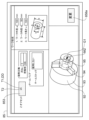
- Fig. 25 is a diagram showing a machine tool system 100A in the first embodiment
- the machining simulation device 1A includes a calculation device 2 and a communication circuit 3. Additionally, the machining simulation device 1A may include a memory 4, a display device 5, and an input device 6. The input device 6 may be incorporated in the display device 5 (more specifically, the display device 5 may be a touch panel display 52 incorporating an input device 6a). Alternatively, or additionally, the machining simulation device 1A may include an input device 6b (e.g., a button, a switch, a lever, a pointing device, a keyboard, etc.) provided separately from the display device 5.
- an input device 6b e.g., a button, a switch, a lever, a pointing device, a keyboard, etc.
- the processing simulation device 1A may be configured by one computer. Alternatively, multiple computers may work together to function as the processing simulation device 1A. In other words, the processing simulation device 1A may include one computer, or may include multiple computers.
- the arithmetic unit 2 includes at least one processor 2a (e.g., at least one CPU).
- the memory 4 is a storage medium that can be read by the calculation device 2.
- the memory 4 may be, for example, a non-volatile or volatile semiconductor memory such as a RAM, a ROM, or a flash memory, or may be a magnetic disk or other type of memory.
- the memory 4 stores a calculation program 41 (e.g., a three-dimensional model creation program 41a, a program origin setting program 41b, a simulation calculation program 41c, and a display program 41d), a machining program 42 used to machine the workpiece 95 into a desired shape (more specifically, the machining program 42 to be executed by the numerically controlled lathe 8A to machine the workpiece 95 into a desired shape), and data 43 (e.g., first dimensional data 43a that specifies the shape of the chuck model, second dimensional data 43b that specifies the shape of the jaw model, third dimensional data 43c that specifies the shape of the workpiece model, position data 43e of the machine model origin, etc.).
- a calculation program 41 e.g., a three-dimensional model creation program 41a, a program origin setting program 41b, a simulation calculation program 41c, and a display program 41d
- a machining program 42 used to machine the workpiece 95 into a desired shape more specifically, the machining program 42 to be executed by
- the memory 4 may be distributed in multiple locations.
- the memory that stores the machining program 42 may be provided separately from the memory that stores the calculation program 41 or the data 43.
- a part of the memory 4 may be located at a position far from the communication circuit 3.
- the memory 4 may provide at least a part of the calculation program 41 or a part of the data 43 to the calculation device 2 via the communication circuit 3.
- At least a part of the data 43 may be input by an operator via the input device 6, and the input data 43 may be stored in the memory 4.
- at least a part of the data 43 may be transmitted from another computer to the machining simulation device 1A. In this case, the calculation device 2 stores the data 43 received via the communication circuit 3 in the memory 4.
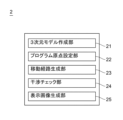
- the calculation device 2 may have a three-dimensional model creation unit 21, a program origin setting unit 22, a movement path generation unit 23, an interference check unit 24, and a display image generation unit 25. More specifically, the calculation device 2 may execute a calculation program 41 stored in the memory 4 to cause the calculation device 2 to function as the three-dimensional model creation unit 21, the program origin setting unit 22, the movement path generation unit 23, the interference check unit 24, and the display image generation unit 25.
- the machine origin G0 of the numerically controlled lathe 8A is the origin on the machine coordinate system of the numerically controlled lathe 8A.
- the machine origin G0 is a reference point of the numerically controlled lathe 8A that is independent of the shape of the workpiece 95.
- the machine coordinate system (X, Y, Z Cartesian coordinate system) of the numerically controlled lathe 8A is set based on the machine origin G0.
- the position of the machine origin G0 may be different for each numerically controlled lathe 8A. In other words, the position of the machine origin G0 is not limited to the position exemplified in FIG. 3.
- the claws 94 are attached to a chuck 93 of a numerically controlled lathe 8A.
- the chuck 93 is attached to a spindle 91 that rotates about a first axis AX1.
- the shape model of the claws 94 (hereinafter referred to as the "claw model 94m") has substantially the same shape as the claws 94 in the machining simulation coordinate system.
- the shape model of the chuck 93 (hereinafter referred to as the "chuck model 93m”) has substantially the same shape as the chuck 93 in the machining simulation coordinate system.
- the workpiece 95 is gripped by a plurality of jaws 94 attached to a chuck 93.
- the shape model of the workpiece 95 (hereinafter referred to as the "workpiece model 95m") has substantially the same shape as the workpiece 95 in the machining simulation coordinate system.
- the calculation device 2 executes the program origin setting program 41b to set the position of the program origin F1, which is the origin on the machining simulation coordinate system. More specifically, the calculation device 2 sets the position of the program origin F1 (see FIG. 4), which is the origin on the machining simulation coordinate system, based on the machine model origin F0 (see FIG. 4) on the machining simulation coordinate system corresponding to the machine origin G0 (see FIG. 3) of the numerically controlled lathe 8A, the above-mentioned claw model 94m, and the above-mentioned work model 95m.
- the machine model origin F0 is a point on the machining simulation coordinate system that simulates the machine origin G0 of the numerically controlled lathe 8A. It is preferable that the position data 43e of the machine model origin F0 is stored in advance in the memory 4.
- the distance from a preset reference surface 910m e.g., the tip surface 911m of the shape model 91m of the spindle 91
- the contact surface between the jaw model 94m and the base end surface 951m of the work model 95m is defined as distance L1.
- the distance from the base end surface 951m of the work model 95m to the tip surface 952m of the work model 95m is defined as distance L2.
- the distance from a preset reference surface 910m (e.g., the tip surface 911m of the shape model 91m of the spindle 91) to the machine model origin F0 is defined as distance L3.
- intersection point CP1 The distance between the machine model origin F0 and the program origin F1 in the direction along the rotation axis AT of the chuck model 93m is defined as distance L4. Furthermore, the intersection point between the rotation axis AT of the chuck model 93m and the first plane PL1 that passes through the machine model origin F0 and is perpendicular to the rotation axis AT is defined as intersection point CP1.
- the calculation device 2 can calculate the above-mentioned distance L1, for example, using the position data of the reference surface 910m stored in the memory 4, the first dimension data 43a stored in the memory 4 for specifying the shape of the chuck model 93m, and the second dimension data 43b stored in the memory 4 for specifying the shape of the jaw model 94m.
- the calculation device 2 can also calculate the above-mentioned distance L2, for example, using the position data of the reference surface 910m stored in the memory 4 and the position data 43e of the machine model origin F0 stored in the memory 4.
- the calculation of the distance L4 is performed using a model in which the bottom of the jaw model 94m and the base end surface 951m of the work model 95m are in contact with each other.
- the calculation device 2 (more specifically, the program origin setting unit 22) can set the position of the program origin F1 to a position moved a distance L4 along the above-mentioned rotation axis AT from the above-mentioned intersection CP1 toward the tip surface 952m of the work model 95m based on the machine model origin F0, the claw model 94m, and the work model 95m.
- the calculation device 2 can accurately set the position of the program origin F1 to a predetermined position of the work model (for example, the intersection CP2 between the above-mentioned rotation axis AT and the tip surface 952m of the work model) regardless of the diversity of the shapes of the claw model and the diversity of the shapes of the work model.
- a reference point G2 e.g., a reference workpiece origin
- a reference point F2 e.g., a reference workpiece model origin
- the position data of the reference point F2 may be stored in the memory 4.
- the reference point F2 (see FIG. 5) is a point in the machining simulation coordinate system that corresponds to the above-mentioned reference point G2 (see FIG. 3).
- the distance between the reference point F2 and the machine model origin F0 in the direction along the rotation axis AT is defined as distance L5.
- the distance between the reference point F2 and the program origin F1 in the direction along the rotation axis AT is defined as distance L6.
- intersection of the rotation axis AT and a second plane PL2 that passes through the reference point F2 and is perpendicular to the rotation axis AT is defined as intersection CP3.
- the calculation device 2 can calculate the above-mentioned distance L5 using the position data of the reference point F2 stored in the memory 4 and the position data 43e of the machine model origin F0.
- the calculation of the distance L6 is performed using a model in which the bottom of the claw model 94m and the base end surface 951m of the work model 95m are in contact with each other.
- the calculation device 2 (more specifically, the program origin setting unit 22) can set the position of the program origin F1 to a position moved a distance L6 along the above-mentioned rotation axis AT from the above-mentioned intersection CP3 toward the tip surface 952m of the work model 95m based on the machine model origin F0, the claw model 94m, and the work model 95m.
- the calculation device 2 can accurately set the position of the program origin F1 to a predetermined position of the work model (for example, the intersection CP2 between the above-mentioned rotation axis AT and the tip surface 952m of the work model) regardless of the diversity of shapes of the claw model and the diversity of shapes of the work model.
- the calculation device 2 sets a machining simulation coordinate system (e.g., an x, y, z Cartesian coordinate system) based on the program origin F1.
- a machining simulation coordinate system e.g., an x, y, z Cartesian coordinate system
- the calculation device 2 executes the machining program 42 using the program origin F1 as a reference position, thereby performing a machining simulation to virtually machine a workpiece model 95m, which is a shape model of the workpiece 95.
- the calculation device 2 executing the machining program 42 includes the calculation device 2 executing the machining program 42 via the calculation program 41 (more specifically, the simulation calculation program 41c).
- the calculation device 2 may process (in other words, interpret) the machining program 42 by executing the calculation program 41.
- the calculation device 2 may perform a machining simulation to virtually machine the workpiece model 95m based on the processing (in other words, based on the interpretation).
- the calculation device 2 may execute the machining program 42 via the simulation calculation program 41c stored in the memory 4, and may also execute the display program 41d stored in the memory 4 to display the simulation image 50A on the display device 5.
- the display program 41d may be a program separate from the simulation calculation program 41c, or may be a program incorporated into the simulation calculation program 41c.
- the numerically controlled lathe 8A includes a plurality of jaws 94 for gripping a workpiece 95, a chuck 93 for supporting the plurality of jaws 94, a spindle 91 for supporting the chuck 93 and rotating about a first axis AX1, a tool rest 96, a first tool holding unit 97 held by the tool rest 96, and a first tool 98 held by the first tool holding unit 97.
- the numerically controlled lathe 8A may also include another tool holding unit 97-2 held by the tool rest 96, and another tool 98-2 held by the other tool holding unit 97-2.
- the numerically controlled lathe 8A may also include a tailstock for pressing the tip surface of the workpiece 95.
- the simulation image 50A includes at least an image of a work model 95m corresponding to the workpiece 95, an image of a plurality of jaw models 94m corresponding to the plurality of jaws 94, an image of a tool rest model 96m corresponding to the tool rest 96, an image of a first tool holding unit model 97m corresponding to the first tool holding unit 97, and an image of a first tool model 98m corresponding to the first tool 98.
- the simulation image 50A may also include an image of another tool holding unit model 97m-2 corresponding to the other tool holding unit 97-2, and an image of another tool model 98m-2 corresponding to the other tool 98-2.
- the simulation image 50A may include an image of a tailstock model 99m corresponding to the tailstock.
- the calculation device 2 (more specifically, the movement path generating unit 23) executes the machining program 42 via the simulation calculation program 41c stored in the memory 4, thereby generating movement path data for the first tool model 98m in the machining simulation coordinate system with the program origin F1 as a reference.
- the calculation device 2 executes the simulation calculation program 41c and the display program 41d stored in the memory 4, thereby displaying, as a simulation image 50A, on the display device 5, a video in which the first tool model 98m and a plurality of models (96m, 97m, 97m-2, 98m-2) that move together with the first tool model 98m move relative to the workpiece model 95m along a path specified by the movement path data.
- the workpiece model 95m is simulated to be machined by the first tool model 98m.
- the calculation device 2 (more specifically, the interference check unit 24) executes the simulation calculation program 41c stored in the memory 4 to check for abnormal interference between the first tool model 98m, which moves along the path specified by the above-mentioned movement path data, and multiple models that move together with the first tool model 98m, and multiple other models (e.g., work model 95m, tailstock model 99m, etc.) in the machining simulation coordinate system.
- abnormal interference refers to interference between models that should not interfere with each other.
- abnormal interference includes (1) interference between the first tool holding unit model 97m attached to the tool rest model 96m and the workpiece model 95m, (2) interference between a tool holding unit model 97m-2 other than the first tool holding unit model 97m attached to the tool rest model 96m, or between a tool model 98m-2 other than the first tool model 98m, and the workpiece model 95m, and (3) interference between the tailstock model 99m and the first tool model 98m moving along a path specified by the above-mentioned movement path data, or multiple models moving together with the first tool model 98m, etc.
- the communication circuit 3 transmits data 43f indicating the position of the above-mentioned program origin F1 (see FIG. 4 or FIG. 5) set by the arithmetic unit 2 to the numerically controlled lathe 8A (see FIG. 8).
- the position of the program origin F1 which is the origin on the machining simulation coordinate system, is set based on the machine model origin F0, the claw model 94m, and the work model 95m.
- the position of the program origin F1 (see FIG. 4 or FIG. 5) relative to the machine model origin F0 can be accurately set on the machining simulation coordinate system. Therefore, a more accurate machining simulation can be performed based on the program origin F1 (see FIG. 6 or FIG. 7).
- the program origin F1 on the machining simulation coordinate system is accurately set, and data 43f indicating the position of the accurately set program origin F1 is transmitted to the numerically controlled lathe 8A.
- the numerically controlled lathe 8A can set the machining program origin using the program origin F1 on the machining simulation coordinate system. Therefore, in order to set the machining program origin, the work of actually measuring the reference position of the workpiece 95 is not necessary, or the work can be simplified.
- the reduction in the setup work performed at the machining site can further improve the operating rate of the numerically controlled lathe 8A.
- the workload of the operator at the machining site is further reduced.
- the energy consumption associated with the setup work is reduced, so the burden on the environment is also reduced.
- the processing simulation device 1A can be installed at the processing site, in an office, or even at the operator's home. When the processing simulation device 1A is installed outside the processing site, the operator's working environment is improved.
- part of the setup work is digitized, promoting DX (digital transformation).
- DX digital transformation
- the numerically controlled lathe 8A includes a control unit 80, a chuck 93, a jaw 94, a spindle 91, a rotary drive unit 90, and a moving unit 87 for moving a tool.
- the numerically controlled lathe 8A may include a tool rest 96 (e.g., a turret 96t) to which a tool holding unit for holding a tool is attached.
- the numerically controlled lathe 8A may include a second rotary drive unit 88 for rotating the turret 96t about a second axis AX2.
- the numerically controlled lathe 8A (more specifically, the tool rest 96) may also include a third rotary drive unit for rotating a tool about the tool axis.
- the chuck 93 supports the claws 94.
- the chuck 93 can move the claws 94 in a direction toward the rotation axis AX of the chuck 93, and can move the claws 94 in a direction away from the rotation axis AX.
- the multiple jaws 94 are attached to the chuck 93 and grip the workpiece 95.
- the spindle 91 supports the chuck 93.
- the spindle 91 also rotates around the first axis AX1 by the driving force of the rotation drive device 90.
- the rotation drive device 90 rotates the spindle 91 around the first axis AX1.
- the first axis AX1 is coaxial with the rotation axis AX of the chuck 93.
- the rotation drive device 90 rotates the spindle 91 around the first axis AX1, the spindle 91, the chuck 93, the multiple jaws 94, and the workpiece 95 rotate integrally around the first axis AX1.
- the moving device 87 moves a first tool 98 that processes the workpiece 95.
- the moving device 87 moves the first tool 98, a first tool holding unit 97 that holds the first tool 98, and a tool rest 96 (e.g., a turret 96t) that supports the first tool holding unit 97, one-dimensionally, two-dimensionally, or three-dimensionally.
- a tool rest 96 e.g., a turret 96t
- the moving device 87 may include a first moving device 87a that moves the tool rest 96 (e.g., turret 96t) in a direction perpendicular to the first axis AX1 and parallel to the horizontal plane (in other words, the Y-axis direction). Additionally, the moving device 87 may include a second moving device 87b that moves the tool rest 96 (e.g., turret 96t) in a direction parallel to the first axis AX1 (in other words, the Z-axis direction). The moving device 87 may also have a third moving device 87c that changes the height of the tool rest 96 (e.g., turret 96t).
- a first moving device 87a that moves the tool rest 96 (e.g., turret 96t) in a direction perpendicular to the first axis AX1 and parallel to the horizontal plane (in other words, the Y-axis direction).
- the moving device 87 may include a
- the control unit 80 controls the controlled devices. More specifically, the control unit 80 controls each of the multiple controlled devices (e.g., the rotation drive device 90, the moving device 87, the second rotation drive device 88, etc.) by transmitting a control command to each of the multiple controlled devices.
- the control unit 80 may be distributed and arranged in multiple locations. In other words, the control unit may be divided into multiple subunits that can communicate with each other.
- the numerically controlled lathe 8A (more specifically, the control unit 80) has a second arithmetic unit 82, a second communication circuit 83, a second memory 84, and a second display device 85. Additionally, the numerically controlled lathe 8A (more specifically, the control unit 80) may have a second input device 86.
- the second input device 86 may be incorporated in the second display device 85 (more specifically, the second display device 85 may be a touch panel display 852 incorporating the second input device 86).
- the numerically controlled lathe 8A may have a second input device (e.g., a button, a switch, a lever, a pointing device, a keyboard, etc.) provided separately from the second display device.
- the second calculation device 82, the second communication circuit 83, the second memory 84, the second display device 85 and/or the second input device 86 are connected to each other via a bus 81.
- the second calculation device 82 includes at least one processor 82a (e.g., at least one CPU).
- the second communication circuit 83 receives data 43f indicating the position of the program origin F1 from the machining simulation device 1A.
- the second memory 84 stores the data 43f indicating the position of the program origin F1 received by the second communication circuit 83.
- the machining simulation device 1A and the program origin F1 have already been explained in the explanation of the machining simulation device 1A in the first embodiment, so repeated explanations of the machining simulation device 1A and the program origin F1 will be omitted.
- the second memory 84 is a storage medium that can be read by the second calculation device 82.
- the second memory 84 may be, for example, a non-volatile or volatile semiconductor memory such as a RAM, a ROM, or a flash memory, or may be a magnetic disk or other type of memory.
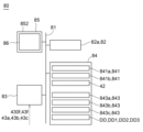
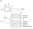
- the second memory 84 stores the calculation program 841, the machining program 42, and data 843 (for example, position data of the machine origin G0, dimensional data specifying the shape of the workpiece 95, etc.).
- the second memory 84 stores a processing calculation program 841a and a second display program 841b.
- the second memory 84 may be distributed across multiple locations.
- the memory that stores the processing program 42 may be provided separately from the memory that stores the calculation program 841 or the data 843.
- the second calculation device 82 sets the position of the machining program origin G1 (see FIG. 10) in the machining program coordinate system based on the position of the program origin F1. It is preferable that the second calculation device 82 sets the position of the machining program origin G1 described above so that the relative position of the machining program origin G1 with respect to the machine origin G0 in the machining program coordinate system (see FIG. 10) is equal to the relative position of the program origin F1 with respect to the machine model origin F0 in the machining simulation coordinate system (see FIG. 4 or FIG. 5).
- the second arithmetic device 82 executes the machining program 42 stored in the second memory 84 to determine the movement path of the first tool 98 in the machining program coordinate system with the machining program origin G1 as a reference.
- the execution of the machining program 42 by the second arithmetic device 82 includes the second arithmetic device 82 executing the machining program 42 via the machining operation program 841a.
- the second arithmetic device 82 may process (in other words, interpret) the machining program 42 by executing the machining operation program 841a.
- the second arithmetic device 82 may determine the movement path of the first tool 98 in the machining program coordinate system with the machining program origin G1 as a reference based on the processing (in other words, based on the interpretation).
- the second arithmetic device 82 generates a movement command 87i to be transmitted to the moving device 87 based on the movement path.
- the movement command 87i (see FIG. 11) generated by the second arithmetic device 82 is transmitted to the moving device 87.
- the second calculation device 82 generates a rotation command 90i by executing the machining program 42 (for example, by executing the machining program 42 via the machining calculation program 841a).
- the rotation command 90i (see FIG. 11) generated by the second calculation device 82 is transmitted to the rotation drive device 90.
- the rotary drive device 90 which receives the rotation command 90i, rotates the spindle 91, the chuck 93, the multiple jaws 94, and the workpiece 95 together around the first axis AX1.
- the movement device 87 which receives the movement command 87i, moves the first tool 98 along the movement path described above.
- the numerically controlled lathe 8A in the first embodiment receives data (e.g., data 43f indicating the position of the program origin F1) from a machining simulation device 1A that executes a high-precision machining simulation.
- data e.g., data 43f indicating the position of the program origin F1
- a machining simulation device 1A that executes a high-precision machining simulation.
- a machining program origin G1 is set in the machining program coordinate system based on the position of the program origin F1 that is accurately set by the machining simulation device 1A (see FIG. 10). Therefore, the task of actually measuring the reference position of the workpiece 95 in order to set the machining program origin is not necessary, or the task can be simplified. Furthermore, by reducing the amount of setup work performed at the machining site, the operating rate of the numerically controlled lathe 8A can be further improved. Furthermore, the workload of the operator at the machining site is further reduced. Furthermore, the energy consumption associated with the setup work is reduced, thereby reducing the burden on the environment.
- Machine tool system 100A Next, the machine tool system 100A in the first embodiment will be described.
- the machine tool system 100A in the first embodiment includes a machining simulation device 1A and a numerically controlled lathe 8A.
- the machining simulation device 1A and the numerically controlled lathe 8A are preferably connected to each other so as to be able to communicate with each other via a network 101.
- the network 101 may be an in-house network or may include an external network (e.g., the Internet).
- the machining simulation device 1A and the numerically controlled lathe 8A have already been explained, so repeated explanations of the machining simulation device 1A and the numerically controlled lathe 8A will be omitted.
- the calculation device 2 (more specifically, the program origin setting unit 22) may calculate an offset amount T1 indicating the relative position of the program origin F1.
- the offset amount T1 is the offset amount of the program origin F1 in the machining simulation coordinate system relative to a reference point F2 (e.g., a reference work model origin) whose position is fixed relative to the machine model origin F0 in the machining simulation coordinate system.
- the offset amount T1 is the offset amount in the z-axis direction (in other words, the direction along the rotation axis AT of the chuck model 93m) (i.e., the z-offset amount).
- the offset amount T1 may be the offset amount of the program origin F1 in the machining simulation coordinate system relative to the machine model origin F0 in the machining simulation coordinate system.
- the offset amount T1 is the offset amount in the z-axis direction (in other words, the direction along the rotation axis AT of the chuck model 93m) (i.e., the z-offset amount).
- the calculation device 2 executes the display program 41d stored in the memory 4 to cause the display device 5 to display the offset amount T1 described above.
- the operator can numerically confirm the relative position of the program origin F1.
- the calculation device 2 (more specifically, the display image generating unit 25) may execute the display program 41d stored in the memory 4 to cause the display device 5 to display the offset amount T1 in a format that can be edited by the operator.
- the operator can use the input device 6 to correct the position of the program origin F1 that was automatically set by the calculation device 2.
- the calculation device 2 may execute the display program 41d to simultaneously display on the display device 5 the above-mentioned offset amount T1, the claw model 94m, the work model 95m, and an image IM indicating the program origin F1.
- the operator can easily grasp the offset amount T1, the arrangement of the claw model 94m and the work model 95m, and the position of the program origin F1.
- the calculation device 2 executes the three-dimensional model creation program 41a and the display program 41d stored in the memory 4, thereby causing the display device 5 to display an assembly model 92m, which is a combination of a chuck model 93m, a jaw model 94m, and a workpiece model 95m, in a three-dimensional display format.
- the operator can easily intuitively grasp the original data used to derive the program origin F1 (or the offset amount T1).
- the machining simulation device 1A may transmit data indicating the offset amount T1 described above to the numerically controlled lathe 8A as data 43f indicating the position of the program origin F1 described above.
- the calculation device 2 (more specifically, the display image generating unit 25) executes the calculation program 41 (more specifically, the display program 41d) stored in the memory 4 to cause the display device 5 to display a setting window 50B for the nail model 94m. Note that when the previously used nail model 94m is to be used as is, the setting of the nail model 94m may be omitted.
- a specific nail model (hereinafter, referred to as specific nail model 94m-s) may be selected via the input device 6 from among a plurality of nail models 94m whose shapes have already been set, and the selected specific nail model 94m-s may be determined as the nail model 94m used to set the position of the program origin F1 described above.
- the arithmetic device 2 may execute the display program 41d stored in the memory 4 to cause the display device 5 to display the second dimension data 43b specifying the shape of the nail model 94m in a format that can be edited by the operator.
- the display device 5 may display an input field 501 in which the value of the second dimension data 43b is input in the setting window 50B.
- the arithmetic device 2 may execute the arithmetic program 41 (more specifically, the three-dimensional model creation program 41a and the display program 41d) stored in the memory 4 to simultaneously display the nail model 94m in a three-dimensional display format, the dimension line S2 added to the nail model 94m in the three-dimensional display format, and the input field 501 in which the length of the dimension line S2 is input.
- the arithmetic device 2 may automatically change the shape of the nail model 94m in the three-dimensional display format and the length of the dimension line S2 based on the value input in the input field 501, and automatically display the changed nail model 94m and the changed dimension line S2 on the display device 5.
- the calculation device 2 determines second dimensional data 43b that specifies the shape of the nail model 94m in response to data being input via the input device 6 for setting the nail model 94m, and stores the determined second dimensional data 43b in the memory 4.
- the calculation device 2 may acquire dimensional data of the nail model created using software such as CAD software via the communication circuit 3 or the like, convert the dimensional data into a format corresponding to the three-dimensional model creation program 41a or the like, and store the converted dimensional data in the memory 4 as second dimensional data 43b that specifies the shape of the nail model 94m.
- the arithmetic device 2 executes the arithmetic program 41 (more specifically, the display program 41d) stored in the memory 4 to display the setting window 50C of the workpiece model 95m on the display device 5.
- the arithmetic device 2 analyzes the machining program 42 to extract a workpiece model (hereinafter referred to as a "designated workpiece model") designated in the machining program 42.
- the arithmetic device 2 executes the display program 41d stored in the memory 4 to display the designated workpiece model on the display device 5 as a default model of the workpiece model 95m used to set the position of the above-mentioned program origin F1.
- the display device 5 may display the dimension data DT1 specifying the shape of the default model in a format that can be edited by the operator.
- the display device 5 may display an input field 502 for changing the value of the dimension data DT1 in the setting window 50C.
- the workpiece model 95m reflecting the change value is set.
- the default model is set as the workpiece model 95m as is.
- the calculation device 2 may execute the calculation program 41 (more specifically, the display program 41d) stored in the memory 4 to display the work model creation window 50D on the display device 5.
- the calculation device 2 executes the display program 41d stored in the memory 4 to display the third dimension data 43c that specifies the shape of the work model 95m in a format that can be edited by the operator.
- the display device 5 may display an input field 503 in which the value of the third dimension data 43c is input in the work model creation window 50D.
- the calculation device 2 may execute the calculation program 41 (more specifically, the three-dimensional model creation program 41a and the display program 41d) stored in the memory 4 to simultaneously display the work model 95m in a three-dimensional display format, the dimension line S3 added to the work model 95m in the three-dimensional display format, and the input field 503 in which the length of the dimension line S3 is input on the display device 5.
- the calculation device 2 may automatically change the shape of the work model 95m in a three-dimensional display format and the length of the dimension line S3 based on the value entered in the input field 503, and automatically display the changed work model 95m and the changed dimension line S3 on the display device 5.
- the calculation device 2 determines third dimensional data 43c that specifies the shape of the work model 95m in response to data being input via the input device 6 for setting the work model 95m, and stores the determined third dimensional data 43c in the memory 4.
- the calculation device 2 may acquire dimensional data of the work model created using software such as CAD software via the communication circuit 3 or the like, convert the dimensional data into a format corresponding to the three-dimensional model creation program 41a or the like, and store the converted dimensional data in the memory 4 as the third dimensional data 43c that specifies the shape of the work model 95m.
- the calculation device 2 (more specifically, the display image generating unit 25) executes the calculation program 41 (more specifically, the display program 41d) stored in the memory 4 to cause the display device 5 to display a setting window 50E for the chuck model 93m.
- the setting of the chuck model 93m may be omitted.
- the calculation device 2 executes the display program 41d stored in the memory 4 to cause the display device 5 to display the first dimension data 43a specifying the shape of the chuck model 93m in a format that can be edited by the operator.
- the display device 5 may display an input field 504 in which the value of the first dimension data 43a is input in the setting window 50E.
- the calculation device 2 may also execute the calculation program 41 (more specifically, the three-dimensional model creation program 41a and the display program 41d) stored in the memory 4 to simultaneously display the chuck model 93m in a three-dimensional display format, the dimension line S1 added to the chuck model 93m in the three-dimensional display format, and the input field 504 in which the length of the dimension line S1 is input, on the display device 5.
- the calculation device 2 may automatically change the shape of the chuck model 93m in a three-dimensional display format and the length of the dimension line S1 based on the value entered in the input field 504, and automatically display the changed chuck model 93m and the changed dimension line S1 on the display device 5.
- the calculation device 2 determines first dimensional data 43a that specifies the shape of the chuck model 93m in response to data being input via the input device 6 for setting the chuck model 93m, and stores the determined first dimensional data 43a in the memory 4.
- the calculation device 2 may acquire dimensional data of the chuck model created using software such as CAD software via the communication circuit 3 or the like, convert the dimensional data into a format corresponding to the three-dimensional model creation program 41a or the like, and store the converted dimensional data in the memory 4 as the first dimensional data 43a that specifies the shape of the chuck model 93m.
- the calculation device 2 executes the calculation program 41 (more specifically, the three-dimensional model creation program 41a) stored in the memory 4 to create an assembly model 92m that combines the chuck model 93m, the jaw model 94m, and the work model 95m, based on the set chuck model 93m, the set jaw model 94m, and the set work model 95m.
- the calculation device 2 (more specifically, the display image generation unit 25) also executes the calculation program 41 (more specifically, the display program 41d) stored in the memory 4 to display the created assembly model 92m on the display device 5.
- the shape of the chuck model 93m can be changed.
- the dimensional data of the chuck model 93m is used in addition to the dimensional data of the jaw model 94m and the dimensional data of the workpiece model 95m.
- the calculation device 2 (more specifically, the program origin setting unit 22) sets the position of the program origin F1, which is the origin on the machining simulation coordinate system, based on the machine model origin F0 on the machining simulation coordinate system corresponding to the machine origin G0 (see FIG. 3) of the numerically controlled lathe 8A, and the assembly model 92m (more specifically, the jaw model 94m, the workpiece model 95m, and the chuck model 93m).
- the distance from a preset reference surface 910m e.g., the tip surface 911m of the shape model 91m of the spindle 91
- the distance from the tip surface 931m of the chuck model 93m to the contact surface between the jaw model 94m and the base end surface 951m of the work model 95m is defined as distance L8.
- the calculation device 2 can calculate the above-mentioned distance L7 and distance L8, for example, using the position data of the reference surface 910m stored in the memory 4, the first dimension data 43a that specifies the shape of the chuck model 93m stored in the memory 4, and the second dimension data 43b that specifies the shape of the jaw model 94m stored in the memory 4.
- the calculation method for "distance L2" and "distance L3" has already been explained, so a repeated explanation of the calculation method for these distances will be omitted.
- the calculation of distance L4 is performed using a model in which the bottom of the jaw model 94m and the base end surface 951m of the work model 95m are in contact with each other.
- the calculation device 2 sets the position of the program origin F1 to a position moved a distance L4 along the rotation axis AT of the chuck model 93m from the intersection CP1 described above toward the tip surface 952m of the work model 95m. In this way, the calculation device 2 can accurately set the position of the program origin F1 to a predetermined position of the work model (for example, the intersection CP2 between the rotation axis AT and the tip surface 952m of the work model described above) regardless of the diversity of shapes of the jaw models, the diversity of shapes of the work model, and the diversity of shapes of the chuck model.
- a reference point G2 e.g., a reference workpiece origin
- a reference point F2 e.g., a reference workpiece model origin
- the position data of the reference point F2 may be stored in the memory 4.
- the reference point F2 is a point in the machining simulation coordinate system that corresponds to the above-mentioned reference point G2 (see FIG. 3).
- the calculation device 2 (more specifically, the program origin setting unit 22) can set the position of the program origin F1 to a position moved a distance L6 along the rotation axis AT of the chuck model 93m from the above-mentioned intersection CP3 toward the tip surface 952m of the work model 95m.
- the calculation device 2 can accurately set the position of the program origin F1 to a predetermined position of the work model (for example, the intersection CP2 between the above-mentioned rotation axis AT and the tip surface 952m of the work model) regardless of the diversity of shapes of the jaw models, the diversity of shapes of the work model, and the diversity of shapes of the chuck model.
- the calculation device 2 sets the position of the above-mentioned program origin F1 based on the machine model origin F0, the jaw model 94m, the workpiece model 95m, and the chuck model 93m. After the position of the program origin F1 is set, the calculation device 2 (more specifically, the movement path generation unit 23 and the interference check unit 24) uses the program origin F1 as a reference position to perform a machining simulation in which the workpiece model 95m is virtually machined. The operations and displays in the machining simulation have already been explained, so repeated explanations of these operations and displays will be omitted.
- the second communication circuit 83 of the numerically controlled lathe 8A receives data 43f indicating the position of the program origin F1 (e.g., data 430f indicating the offset amount T1 of the program origin F1) from the machining simulation device 1A.
- the second memory 84 stores the data 43f indicating the position of the program origin F1 received by the second communication circuit 83 (e.g., data 430f indicating the offset amount T1 of the program origin F1).
- the second calculation device 82 executes the second display program 841b stored in the second memory 84 to cause the second display device 85 to display the offset amount T1 of the program origin F1 (in other words, the offset amount T1 of the program origin F1 relative to the machine model origin F0 or a reference point F2 whose position is fixed relative to the machine model origin F0).
- the above-mentioned offset amount T1 functions as a default value for the offset amount (hereinafter referred to as the "second offset amount T2") of the machining program origin G1 relative to the machine origin G0 or a reference point G2 whose position is fixed relative to the machine origin G0 (see FIG. 3).
- FIG. 10 shows a schematic example of the second offset amount T2.
- the second offset amount T2 is the offset amount in the Z-axis direction (in other words, the direction along the rotation axis AX of the chuck 93) (i.e., the Z offset amount).
- the offset amount T1 set in the machining simulation device 1A functions as a default value for the second offset amount T2 set in the numerically controlled lathe 8A, so that the setting work of the second offset amount T2 in the numerically controlled lathe 8A is omitted or the setting work is simplified (for example, the second offset amount T2 can be set without actually measuring the reference position of the workpiece 95).
- the second calculation device 82 may execute the display program 41d stored in the memory 4 to cause the second display device 85 to display the above-mentioned offset amount T1 (in other words, the default value DD of the second offset amount) in a format that can be edited by the operator.
- the second display device 85 may display an input field 853 for changing the default value DD of the second offset amount T2 to another value.
- the second arithmetic unit 82 sets the position of the machining program origin G1 based on the second offset amount T2 and the machine origin G0 or a reference point G2 whose position is fixed relative to the machine origin G0 (see FIG. 10).
- the second arithmetic unit 82 also executes the machining program 42 stored in the second memory 84 (for example, by executing the machining program 42 via the machining arithmetic program 841a) to determine the movement path of the first tool 98 in the machining program coordinate system with the machining program origin G1 as a reference.
- the second arithmetic unit 82 also generates a movement command 87i to be transmitted to the movement device 87 based on the movement path.
- the movement command 87i (see FIG.
- the second arithmetic unit 82 also generates a rotation command 90i by executing the machining program 42 (for example, by executing the machining program 42 via the machining arithmetic program 841a).
- the rotation command 90i (see FIG. 11) generated by the second calculation device 82 is sent to the rotation drive device 90. In this way, the first tool 98 moves along the movement path, and the workpiece 95 is machined by the first tool 98.
- the second communication circuit 83 of the numerically controlled lathe 8A may receive the second dimension data 43b specifying the shape of the jaw model 94m and the third dimension data 43c specifying the shape of the workpiece model 95m from the machining simulation device 1A. Additionally, the second communication circuit 83 may receive the first dimension data 43a specifying the shape of the chuck model 93m from the machining simulation device 1A.
- the second memory 84 may store the second dimension data 43b, which specifies the shape of the claw model 94m and is received via the second communication circuit 83, as default data for the fifth dimension data 843b, which specifies the shape of the claw 94 (hereinafter referred to as "first default data DD1").
- the second memory 84 may store the third dimension data 43c, which specifies the shape of the workpiece model 95m and is received via the second communication circuit 83, as default data for the sixth dimension data 843c, which specifies the shape of the workpiece 95 (hereinafter referred to as "second default data DD2").
- the second memory 84 may also store the first dimension data 43a, which specifies the shape of the chuck model 93m and is received via the second communication circuit 83, as default data for the fourth dimension data 843a, which specifies the shape of the chuck 93 (hereinafter referred to as "third default data DD3").
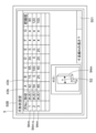
- the second calculation device 82 may execute the second display program 841b stored in the second memory 84 to cause the second display device 85 to display an assembly 92, which is a combination of a chuck 93, jaws 94, and a workpiece 95, in a three-dimensional display format based on default data (DD1, DD2, DD3).
- the second display device 85 may simultaneously display a three-dimensional image of the assembly 92 and an image IM2 indicating a machining program origin G1, which will be described later.
- the second calculation device 82 executes the second display program 841b stored in the second memory 84 to cause the second display device 85 to display the first default data DD1 specifying the shape of the nail 94 in a format that can be edited by the operator.
- the second display device 85 may display an input field 854 for changing the value of the first default data DD1 to another value.
- a numerical value is entered into the input field 854, and the change operation unit 858b (more specifically, the change operation image displayed on the second display device 85) is operated, whereby the fifth dimension data 843b specifying the shape of the nail 94 is changed based on the numerical value entered into the input field 854.
- the second calculation device 82 may display a message MG1 on the second display device 85 recommending that the machining simulation be performed again in response to any value of the first default data DD1 being changed beyond a preset allowable value.
- the second calculation device 82 may display a message MG1 on the second display device 85 recommending that the machining simulation be performed again in response to the deviation amount of the shape of the claw 94 from the shape of the claw model 94m exceeding the allowable amount.
- the second calculation device 82 executes the second display program 841b stored in the second memory 84, thereby causing the second display device 85 to display the second default data DD2 specifying the shape of the workpiece 95 in a format that can be edited by the operator.
- the second display device 85 may display an input field 855 for changing the value of the second default data DD2 to another value.
- a numerical value is entered into the input field 855, and the change operation unit 858c (more specifically, the change operation image displayed on the second display device 85) is operated, whereby the sixth dimension data 843c specifying the shape of the workpiece 95 is changed based on the numerical value entered into the input field 855.
- the second calculation device 82 may display a message MG2 on the second display device 85 recommending that the machining simulation be performed again in response to any value of the second default data DD2 being changed beyond a preset allowable value.
- the second calculation device 82 may display a message MG2 on the second display device 85 recommending that the machining simulation be performed again in response to the deviation amount of the shape of the workpiece 95 from the shape of the workpiece model 95m exceeding the allowable amount.
- FIG. 26 is a flowchart showing an example of the processing simulation method according to the first embodiment.
- the machining simulation method in the first embodiment is executed using the machining simulation device 1A in the first embodiment or another machining simulation device.
- the machining simulation device 1A in the first embodiment has already been described, so a repeated description of the machining simulation device 1A in the first embodiment will be omitted.
- the first step ST1 is a first setting process.
- the first setting process includes the calculation device 2 of the machining simulation device 1 determining third dimension data 43c that specifies the shape of the workpiece model 95m, and the memory 4 storing the determined third dimension data 43c.
- the first setting step may include the calculation device 2 analyzing the machining program 42 to extract a work model 95m specified in the machining program 42, and the calculation device 2 determining third dimension data 43c that specifies the shape of the work model 95m based on the extracted work model 95m.
- the first setting step may include the calculation device 2 determining third dimension data 43c that specifies the shape of the work model 95m in response to input of data for setting the work model 95m via the input device 6.
- the first setting step may include the calculation device 2 reading out a previously created work model 95m from the memory 4, and the calculation device 2 determining third dimension data 43c that specifies the shape of the work model 95m based on the read work model 95m.
- the work model 95m may be displayed on the display device 5.
- displaying the work model 95m on the display device 5 may include displaying the third dimension data 43c that specifies the shape of the work model 95m on the display device 5 in a format that can be edited by the operator.
- the display device 5 simultaneously displays the work model 95m in a three-dimensional display format, the dimension line S3 added to the work model 95m in the three-dimensional display format, and an input field 503 in which the length of the dimension line S3 is input.
- the calculation device 2 automatically changes the shape of the work model 95m in the three-dimensional display format and the length of the dimension line S3 based on the value input in the input field 503, and automatically displays the changed work model 95m and the changed dimension line S3 on the display device 5.
- the second step ST2 is a second setting process.
- the second setting process includes the calculation device 2 determining second dimensional data 43b that specifies the shape of the nail model 94m, and the memory 4 storing the determined second dimensional data 43b.
- the second setting step may include the calculation device 2 determining second dimensional data 43b that specifies the shape of the nail model 94m in response to input of data for setting the nail model 94m via the input device 6.
- the second setting step may include the calculation device 2 reading out a nail model 94m created in the past from the memory 4, and the calculation device 2 determining second dimensional data 43b that specifies the shape of the nail model 94m based on the read nail model 94m.
- the nail model 94m may be displayed on the display device 5.
- displaying the nail model 94m on the display device 5 may include displaying the second dimension data 43b specifying the shape of the nail model 94m on the display device 5 in a format that can be edited by the operator.
- the display device 5 simultaneously displays the nail model 94m in a three-dimensional display format, the dimension line S2 added to the nail model 94m in the three-dimensional display format, and an input field 501 in which the length of the dimension line S2 is input.
- the calculation device 2 automatically changes the shape of the nail model 94m in the three-dimensional display format and the length of the dimension line S2 based on the value input in the input field 501, and automatically displays the changed nail model 94m and the changed dimension line S2 on the display device 5.
- the second step ST2 may be performed after the first step ST1 or before the first step ST1.
- the third step ST3 is a third setting process.
- the third setting process includes the calculation device 2 determining first dimension data 43a that specifies the shape of the chuck model 93m, and the memory 4 storing the determined first dimension data 43a.
- the third setting step may include the calculation device 2 determining first dimensional data 43a that specifies the shape of the chuck model 93m in response to input of data for setting the chuck model 93m via the input device 6.
- the third setting step may include the calculation device 2 reading out a previously created chuck model 93m from the memory 4, and the calculation device 2 determining first dimensional data 43a that specifies the shape of the chuck model 93m based on the read chuck model 93m.
- the chuck model 93m may be displayed on the display device 5.
- displaying the chuck model 93m on the display device 5 may include displaying the first dimension data 43a specifying the shape of the chuck model 93m on the display device 5 in a format that can be edited by the operator.
- the display device 5 simultaneously displays the chuck model 93m in a three-dimensional display format, the dimension line S1 added to the chuck model 93m in the three-dimensional display format, and an input field 504 in which the length of the dimension line S1 is input.
- the calculation device 2 automatically changes the shape of the chuck model 93m in the three-dimensional display format and the length of the dimension line S1 based on the value input in the input field 504, and automatically displays the changed chuck model 93m and the changed dimension line S1 on the display device 5.
- the third step ST3 may be performed after the first step ST1 and the second step ST2, or before the first step ST1 and the second step ST2. Alternatively, the third step ST3 may be performed between the first step ST1 and the second step ST2. Note that the third step ST3 may be omitted.
- a fourth step ST4 the calculation device 2 creates an assembly model 92m that combines the work model 95m, the jaw model 94m, and the chuck model 93m.
- the fourth step ST4 is an assembly model creation process.
- the assembly model creation process preferably includes checking whether the created assembly model 92m is normal (in other words, a check process).
- the check process includes, for example, checking whether the jaw model 94m has a shape suitable for gripping the work model 95m. If the assembly model 92m is not normal, the calculation device 2 may cause the display device 5 to display an alert.
- the assembly model 92m created by the assembly model creation process may be displayed on the display device 5.
- the fifth step ST5 is a program origin setting process.
- the program origin setting process may be configured to be automatically executed by the computing device 2 by operating the origin setting operation unit 55 (more specifically, the origin setting operation unit 55a displayed on the display device 5).
- the calculation device 2 sets the position of the program origin F1, which is the origin on the machining simulation coordinate system, based on the machine model origin F0 on the machining simulation coordinate system corresponding to the machine origin G0 of the numerically controlled lathe 8, the claw model 94m, which is a shape model of the claw 94 attached to the chuck 93 of the numerically controlled lathe 8, and the workpiece model 95m, which is a shape model of the workpiece 95 gripped by the multiple claws 94.
- the calculation device 2 sets the position of the program origin F1 taking into consideration the shape of the chuck model 93m. More specifically, as illustrated in FIG. 18 or FIG. 19, in the program origin setting step, the calculation device 2 sets the position of the program origin F1, which is the origin on the machining simulation coordinate system, based on the above-mentioned machine model origin F0, the above-mentioned jaw model 94m, the above-mentioned workpiece model 95m, and the chuck model 93m.
- the program origin setting step (fifth step ST5) preferably includes storing data 43f indicating the position of the program origin F1 set by the calculation device 2 in the memory 4.
- the data 43f indicating the position of the program origin F1 may be data indicating the offset amount T1 of the program origin F1 with respect to the machine model origin F0 or a reference point F2 whose position is fixed with respect to the machine model origin F0.
- the sixth step ST6 is a display step.
- the display step may include simultaneously displaying the above-mentioned offset amount T1, the claw model 94m in a three-dimensional display format, the workpiece model 95m in a three-dimensional display format, and an image IM indicating the program origin F1 on the display device 5.
- the display step may also include displaying the above-mentioned offset amount T1 on the display device 5 in a format that can be edited by the operator.
- the display step (sixth step ST6) may be omitted.
- the seventh step ST7 a machining simulation is performed to virtually machine the workpiece model 95m.
- the seventh step ST7 is a machining simulation execution process.
- the machining simulation execution process includes the calculation device 2 (more specifically, the movement path generation unit 23 and the interference check unit 24) performing a machining simulation to virtually machine the workpiece model 95m by executing the machining program 42 using the program origin F1 as a reference position.
- the machining simulation execution process includes the calculation device 2 generating movement path data for the first tool model 98m that simulates machining of the workpiece model 95m in the machining simulation coordinate system, based on the program origin F1.
- the machining simulation execution process may include displaying on the display device 5 a video in which the first tool model 98m and a number of models (96m, 97m, 97m-2, 98m-2) moving together with the first tool model 98m move relative to the workpiece model 95m along a path specified by the above-mentioned movement path data.
- the workpiece model 95m is simulated to be machined by the first tool model 98m.
- the machining simulation execution process may include the calculation device 2 checking whether or not there is abnormal interference between the first tool model 98m and a plurality of models that move together with the first tool model 98m, and a plurality of other models (e.g., the work model 95m, the tailstock model 99m, etc.).
- the machining simulation execution process may also include displaying a message indicating that there is abnormal interference on the display device 5 when the calculation device 2 determines that there is abnormal interference.
- step ST8 data (43a, 43b, 43c, 43f) is transmitted from the communication circuit 3 of the machining simulation device 1 to the numerically controlled lathe 8.
- the tenth step ST10 is a data transmission process.
- the data transmission process includes transmitting data 43f (for example, the offset amount T1 described above) indicating the position of the program origin F1, which is the origin on the machining simulation coordinate system, from the communication circuit 3 of the machining simulation device 1 to the numerically controlled lathe 8.
- data 43f for example, the offset amount T1 described above
- the data transmission process may include transmitting second dimension data 43b specifying the shape of the jaw model 94m and third dimension data 43c specifying the shape of the workpiece model 95m from the communication circuit 3 of the machining simulation device 1 to the numerically controlled lathe 8.
- the data transmission process may also include transmitting first dimension data 43a specifying the shape of the chuck model 93m from the communication circuit 3 of the machining simulation device 1 to the numerically controlled lathe 8.
- the data transmission process may also include transmitting execution result data of the machining simulation (e.g., data indicating that no abnormal interference occurred in the machining simulation) from the communication circuit 3 of the machining simulation device 1 to the numerically controlled lathe 8.
- execution result data of the machining simulation e.g., data indicating that no abnormal interference occurred in the machining simulation
- the calculation program 41 in the first embodiment is a program for causing the processing simulation device 1 to execute the processing simulation method in the first embodiment.
- the program in the first embodiment includes the steps of: (1) setting the position of the program origin F1, which is the origin on the machining simulation coordinate system, based on a machine model origin F0 on the machining simulation coordinate system corresponding to the machine origin G0 of the numerically controlled lathe 8, a claw model 94m which is a shape model of the claw 94 attached to the chuck 93 of the numerically controlled lathe 8, and a workpiece model 95m which is a shape model of the workpiece 95 gripped by the multiple claws 94 (in other words, the above-mentioned fifth step ST5); and (2) setting the position of the program origin F1, which is the origin on the machining simulation coordinate system, based on the program origin F1.
- a machining simulation method that includes a process of performing a machining simulation in which the workpiece model 95m is virtually machined by executing the machining program 42 using the program origin F1 as a reference position (e.g., by interpreting the machining program 42 using the program origin F1 as a reference position) (in other words, the seventh step ST7 described above); and (3) a process
- the program in the first embodiment may be a program for causing the processing simulation device 1 to execute the processing simulation method including the above-mentioned first setting step (first step ST1) and/or the above-mentioned second setting step (second step ST2).
- the program in the first embodiment may be a program for causing the processing simulation device 1 to execute the processing simulation method including the above-mentioned third setting step (third step ST3).
- the program in the first embodiment may be a program for causing the processing simulation device 1 to execute the processing simulation method including the above-mentioned assembly model creation step (fourth step ST4).
- the program in the first embodiment may be a program for causing the processing simulation device 1 to execute the processing simulation method including the above-mentioned display step (sixth step ST6).
- the program (more specifically, the calculation program 41) may be a program for causing the machining simulation device 1 to execute a machining simulation method including the steps of: (1) simultaneously displaying, on the display device 5, a nail model 94m in a three-dimensional display format, a dimension line S2 added to the nail model 94m in a three-dimensional display format, and an input field 501 in which the length of the dimension line S2 is input; and (2) automatically changing the shape of the nail model 94m in a three-dimensional display format and the length of the dimension line S2 based on the value input into the input field 501, and automatically displaying the changed nail model 94m and the changed dimension line S2 on the display device 5.
- the memory 4 in the first embodiment may be a non-volatile storage medium on which the above-mentioned program (more specifically, the calculation program 41) is recorded.
- the non-volatile storage medium on which the above-mentioned program (more specifically, the calculation program 41) is recorded may be a portable storage medium 4M, as exemplified in FIG. 28.
- the machining simulation method and program (more specifically, the calculation program 41) in the first embodiment, or the non-volatile storage medium on which the program (more specifically, the calculation program 41) is recorded, achieves the same effects as the machining simulation device 1A in the first embodiment.
- FIG. 26 and 27 are flow charts showing an example of the workpiece machining method in the first embodiment.
- the workpiece machining method in the first embodiment is performed using the machine tool system 100A in the first embodiment or another machine tool system.
- the machine tool system 100A in the first embodiment (more specifically, the machining simulation device 1A and the numerically controlled lathe 8A) have already been described, so a repeated description of the machine tool system 100A in the first embodiment will be omitted.
- the workpiece machining method in the first embodiment includes: (1) a step of setting the position of a program origin F1, which is the origin on the machining simulation coordinate system, based on a machine model origin F0 on the machining simulation coordinate system corresponding to a machine origin G0 of the numerically controlled lathe 8, a claw model 94m which is a shape model of a claw 94 attached to a chuck 93 of the numerically controlled lathe 8, and a workpiece model 95m which is a shape model of a workpiece 95 gripped by the multiple claws 94 (in other words, the above-mentioned fifth step ST5); and (2) a step of setting the position of a program origin F1, which is the origin on the machining simulation coordinate system, based on the machine model origin F0 on the machining simulation coordinate system corresponding to a machine origin G0 of the numerically controlled lathe 8, a claw model 94m which is a shape model of a claw 94 attached to a chuck 93 of the numerically controlled lathe 8, and a work
- the workpiece machining method in the first embodiment may include the above-mentioned first setting step (first step ST1) and/or the above-mentioned second setting step (second step ST2). Alternatively, or additionally, the workpiece machining method in the first embodiment may include the above-mentioned third setting step (third step ST3). Alternatively, or additionally, the workpiece machining method in the first embodiment may include the above-mentioned assembly model creation step (fourth step ST4). Alternatively, or additionally, the workpiece machining method in the first embodiment may include the above-mentioned display step (sixth step ST6). Also, the workpiece machining method in the first embodiment may include the above-mentioned data transmission step (eighth step ST8).
- the first step ST1 to the eighth step ST8 have already been explained in the machining simulation method of the first embodiment, so repeated explanations of the first step ST1 to the eighth step ST8 will be omitted.
- the second communication circuit 83 of the numerically controlled lathe 8 receives data (43a, 43b, 43c, 43f) from the machining simulation device 1.
- the ninth step ST9 is a data receiving process.
- the data receiving process includes the second communication circuit 83 of the numerically controlled lathe 8 receiving data 43f indicating the position of the program origin F1, which is the origin on the machining simulation coordinate system, from the machining simulation device 1 (for example, data 430f indicating the offset amount T1 described above).
- the data receiving process may include the second communication circuit 83 of the numerically controlled lathe 8 receiving, from the machining simulation device 1, second dimensional data 43b specifying the shape of the jaw model 94m and third dimensional data 43c specifying the shape of the workpiece model 95m.
- the data receiving process may also include the second communication circuit 83 of the numerically controlled lathe 8 receiving, from the machining simulation device 1, first dimensional data 43a specifying the shape of the chuck model 93m.
- the data receiving process may also include the second communication circuit 83 of the numerically controlled lathe 8 receiving execution result data of the machining simulation (e.g., data indicating that there was no abnormal interference in the machining simulation) from the machining simulation device 1.
- execution result data of the machining simulation e.g., data indicating that there was no abnormal interference in the machining simulation
- the data (43a, 43b, 43c, 43f, 430f) received via the second communication circuit 83 is stored in the second memory 84.
- data 43f indicating the position of the program origin F1 (more specifically, data 430f indicating the offset amount T1 described above) is stored in the second memory 84.
- first dimensional data 43a specifying the shape of the chuck model 93m, second dimensional data 43b specifying the shape of the jaw model 94m, and third dimensional data 43c specifying the shape of the work model 95m are stored in the second memory 84.
- the offset amount T1 described above is displayed on the second display device 85.
- the tenth step ST10 is the second display step.
- the second display step includes displaying, on the second display device 85, the offset amount T1 of the program origin F1 relative to the machine model origin F0 or a reference point F2 whose position is fixed relative to the machine model origin F0.
- the offset amount T1 described above functions as a default value DD of the second offset amount T2, which is the offset amount of the machining program origin G1 relative to the machine origin G0 or a reference point G2 (see FIG. 10) whose position is fixed relative to the machine origin G0.
- the offset amount T1 set in the machining simulation device 1 functions as the default value DD of the second offset amount T2 set in the numerically controlled lathe 8, so that the setting work of the second offset amount T2 in the numerically controlled lathe 8 is omitted or the setting work is simplified (for example, the second offset amount T2 can be set without actually measuring the reference position of the workpiece 95).
- the second display step may include displaying the above-mentioned offset amount T1 (in other words, the default value DD of the above-mentioned second offset amount T2) on the second display device 85 in a format that can be edited by the operator.
- the second display step may include displaying a message on the second display device 85 recommending that the machining simulation be performed again in response to the default value DD being changed beyond a preset allowable value.
- the dimension data (more specifically, the fifth dimension data 843b) specifying the shape of the nail 94 is displayed on the second display device 85.
- the eleventh step ST11 is the third display step.
- the second display device 85 may display data specifying the shape of the nail model 94m as the first default data DD1 of the fifth dimension data 843b.
- the second display device 85 may display the first default data DD1 in a format that can be edited by the operator. More specifically, the second display device 85 may display an input field 854 for changing the value of the first default data DD1 to another value.
- the fifth dimension data 843b displayed on the second display device 85 may be changed based on the numerical value input in the input field 854 by inputting a numerical value in the input field 854 and operating the change operation unit 858b.
- the third display step may include displaying a message MG1 on the second display device 85 recommending that the machining simulation be performed again in response to any value of the first default data DD1 being changed beyond a preset allowable value.
- the dimension data (more specifically, the sixth dimension data 843c) specifying the shape of the workpiece 95 is displayed on the second display device 85.
- the twelfth step ST12 is the fourth display step.
- the second display device 85 may display data specifying the shape of the workpiece model 95m as the second default data DD2 of the sixth dimension data 843c.
- the second display device 85 may display the second default data DD2 in a format that can be edited by the operator. More specifically, the second display device 85 may display an input field 855 for changing the value of the second default data DD2 to another value.
- the sixth dimension data 843c displayed on the second display device 85 may be changed based on the numerical value entered in the input field 855 by entering a numerical value in the input field 855 and operating the change operation unit 858c.
- the fourth display step may include displaying a message MG2 on the second display device 85 recommending that the machining simulation be performed again in response to any value of the second default data DD2 being changed beyond a preset allowable value.
- the tenth step ST10 to the twelfth step ST12 may be performed in any order. Furthermore, the tenth step ST10 and the twelfth step ST12 may be performed simultaneously, or the eleventh step ST11 and the twelfth step ST12 may be performed simultaneously. Furthermore, each of the tenth step ST10 to the twelfth step ST12 may be omitted.
- step ST13 the position of the machining program origin G1 in the machining program coordinate system is set based on the position of the program origin F1.
- Step ST13 is a machining program origin setting process.
- the machining program origin setting process includes the second calculation device 82 setting the position of the machining program origin G1 so that the relative position of the machining program origin G1 with respect to the machine origin G0 in the machining program coordinate system is equal to the relative position of the program origin F1 with respect to the machine model origin F0 (see FIG. 4, FIG. 5, FIG. 18, or FIG. 19).
- the machining program origin setting step may include the second calculation device 82 setting the position of the machining program origin G1 so that the second offset amount T2 of the machining program origin G1 with respect to the machine origin G0 or a reference point G2 whose position is fixed with respect to the machine origin G0 is equal to the above-mentioned offset amount T1. Furthermore, if the second offset amount T2 is corrected in the tenth step ST10, the machining program origin setting step may include correcting the position of the machining program origin G1 based on the difference between the second offset amount T2 after correction and the second offset amount T2 before correction.
- step ST14 the workpiece 95 is machined by the numerically controlled lathe 8, which executes the machining program 42 using the machining program origin G1 as a reference position.
- Step ST14 is a machining process.
- the machining process includes determining the movement path of the first tool 98 based on the machining program origin G1.
- the machining process also includes the second calculation device 82 sending a control command to each of a plurality of controlled devices (e.g., the movement device 87, the rotary drive device 90, etc.).
- the machining process includes: (1) the second arithmetic unit 82 generating a movement command 87i based on a movement path of the first tool 98 determined with reference to the machining program origin G1; (2) the second arithmetic unit 82 transmitting the movement command 87i to the movement device 87; and (3) the movement device 87 receiving the movement command 87i moving the first tool 98 along the movement path.
- the machining process also includes: (4) the second arithmetic unit 82 transmitting a rotation command 90i to the rotation drive device 90; and (5) the rotation drive device 90 receiving the rotation command 90i rotating the spindle 91, the chuck 93, the multiple jaws 94, and the workpiece 95 together around the first axis AX1.
- a highly accurate machining simulation is performed in advance.
- a highly accurate machining simulation it is possible to omit or simplify the interference check performed using the numerically controlled lathe 8.
- By omitting or simplifying the interference check at the machining site it is possible to improve the operating rate of the numerically controlled lathe 8. In addition, the workload of the operator at the machining site is reduced.
- the machining program origin G1 in the machining program coordinate system is set based on the position of the program origin F1, which is the origin on the machining simulation coordinate system that is accurately set in the machining simulation. Therefore, the task of actually measuring the reference position of the workpiece 95 in order to set the machining program origin is not necessary, or the task can be simplified.
- the operating rate of the numerically controlled lathe 8A can be further improved.
- the workload of the operator at the machining site is further reduced.
- the burden on the environment is also reduced because the energy consumption associated with the setup work is reduced.
Landscapes
- Engineering & Computer Science (AREA)
- Physics & Mathematics (AREA)
- Human Computer Interaction (AREA)
- Manufacturing & Machinery (AREA)
- General Physics & Mathematics (AREA)
- Automation & Control Theory (AREA)
- Geometry (AREA)
- Numerical Control (AREA)
- Turning (AREA)
- Machine Tool Sensing Apparatuses (AREA)
Priority Applications (5)
| Application Number | Priority Date | Filing Date | Title |
|---|---|---|---|
| JP2023507557A JP7280455B1 (ja) | 2022-11-01 | 2022-11-01 | 加工シミュレーション装置、数値制御旋盤、工作機械システム、ワーク加工方法、および、プログラム |
| EP22964389.5A EP4509261A4 (en) | 2022-11-01 | 2022-11-01 | MACHINING SIMULATION DEVICE, CNC LATHE, MACHINE TOOL SYSTEM, WORKPIECE MACHINING PROCESS AND PROGRAM |
| CN202280099440.XA CN119768248B (zh) | 2022-11-01 | 2022-11-01 | 加工模拟装置、数控车床、机床系统、工件加工方法和计算机可读取的存储介质 |
| PCT/JP2022/040901 WO2024095367A1 (ja) | 2022-11-01 | 2022-11-01 | 加工シミュレーション装置、数値制御旋盤、工作機械システム、ワーク加工方法、および、プログラム |
| US18/977,832 US20250103023A1 (en) | 2022-11-01 | 2024-12-11 | Machining simulation apparatus, numerically controlled lathe, machine tool system, and method for machining workpiece |
Applications Claiming Priority (1)
| Application Number | Priority Date | Filing Date | Title |
|---|---|---|---|
| PCT/JP2022/040901 WO2024095367A1 (ja) | 2022-11-01 | 2022-11-01 | 加工シミュレーション装置、数値制御旋盤、工作機械システム、ワーク加工方法、および、プログラム |
Related Child Applications (1)
| Application Number | Title | Priority Date | Filing Date |
|---|---|---|---|
| US18/977,832 Continuation US20250103023A1 (en) | 2022-11-01 | 2024-12-11 | Machining simulation apparatus, numerically controlled lathe, machine tool system, and method for machining workpiece |
Publications (1)
| Publication Number | Publication Date |
|---|---|
| WO2024095367A1 true WO2024095367A1 (ja) | 2024-05-10 |
Family
ID=86395870
Family Applications (1)
| Application Number | Title | Priority Date | Filing Date |
|---|---|---|---|
| PCT/JP2022/040901 Ceased WO2024095367A1 (ja) | 2022-11-01 | 2022-11-01 | 加工シミュレーション装置、数値制御旋盤、工作機械システム、ワーク加工方法、および、プログラム |
Country Status (5)
| Country | Link |
|---|---|
| US (1) | US20250103023A1 (https=) |
| EP (1) | EP4509261A4 (https=) |
| JP (1) | JP7280455B1 (https=) |
| CN (1) | CN119768248B (https=) |
| WO (1) | WO2024095367A1 (https=) |
Families Citing this family (1)
| Publication number | Priority date | Publication date | Assignee | Title |
|---|---|---|---|---|
| JP7528347B1 (ja) | 2023-12-13 | 2024-08-05 | Dmg森精機株式会社 | 情報処理装置、ncプログラムの生成方法およびプログラム |
Citations (4)
| Publication number | Priority date | Publication date | Assignee | Title |
|---|---|---|---|---|
| JPS60180749A (ja) * | 1984-02-29 | 1985-09-14 | Yamazaki Mazak Corp | 数値制御旋盤における加工基準点の補正制御方法 |
| JPS6254604A (ja) * | 1985-08-30 | 1987-03-10 | Yamazaki Mazak Corp | ワ−ク座標系設定制御方法 |
| JPH04131910A (ja) * | 1990-09-25 | 1992-05-06 | Hitachi Seiki Co Ltd | 数値制御旋盤のワーク座標シフト量の設定方法およびその装置 |
| JPH05261647A (ja) * | 1992-03-19 | 1993-10-12 | Yamazaki Mazak Corp | 自動加工装置 |
Family Cites Families (9)
| Publication number | Priority date | Publication date | Assignee | Title |
|---|---|---|---|---|
| JPH09212222A (ja) * | 1996-02-02 | 1997-08-15 | Honda Motor Co Ltd | 歯車の加工シミュレーションシステムおよびシミュレーション方法 |
| JPH1145106A (ja) * | 1997-07-28 | 1999-02-16 | Fanuc Ltd | 対話形数値制御装置 |
| DE602004027494D1 (de) * | 2003-07-04 | 2010-07-15 | Mitsubishi Electric Corp | Automatisches programmierverfahren und einrichtung |
| DE102006043390B4 (de) * | 2006-09-15 | 2010-05-27 | Dmg Electronics Gmbh | Vorrichtung und Verfahren zur Simulation eines Ablaufs zur Bearbeitung eines Werkstücks an einer Werkzeugmaschine |
| JP2009053823A (ja) * | 2007-08-24 | 2009-03-12 | Okuma Corp | 加工シミュレーション装置 |
| JP2019152936A (ja) * | 2018-02-28 | 2019-09-12 | ファナック株式会社 | 工作機械の加工シミュレーション装置 |
| JP6730358B2 (ja) * | 2018-03-29 | 2020-07-29 | ファナック株式会社 | シミュレーション装置 |
| CN110319746B (zh) * | 2019-06-10 | 2022-04-15 | 西安爱德华测量设备股份有限公司 | 一种基于自动化机精密加工的机床外工况模拟机测量方法 |
| WO2021014571A1 (ja) * | 2019-07-23 | 2021-01-28 | ヤマザキマザック株式会社 | 工作機械、工作機械のための入力支援方法、及び工作機械のためのプログラム |
-
2022
- 2022-11-01 JP JP2023507557A patent/JP7280455B1/ja active Active
- 2022-11-01 WO PCT/JP2022/040901 patent/WO2024095367A1/ja not_active Ceased
- 2022-11-01 CN CN202280099440.XA patent/CN119768248B/zh active Active
- 2022-11-01 EP EP22964389.5A patent/EP4509261A4/en active Pending
-
2024
- 2024-12-11 US US18/977,832 patent/US20250103023A1/en active Pending
Patent Citations (4)
| Publication number | Priority date | Publication date | Assignee | Title |
|---|---|---|---|---|
| JPS60180749A (ja) * | 1984-02-29 | 1985-09-14 | Yamazaki Mazak Corp | 数値制御旋盤における加工基準点の補正制御方法 |
| JPS6254604A (ja) * | 1985-08-30 | 1987-03-10 | Yamazaki Mazak Corp | ワ−ク座標系設定制御方法 |
| JPH04131910A (ja) * | 1990-09-25 | 1992-05-06 | Hitachi Seiki Co Ltd | 数値制御旋盤のワーク座標シフト量の設定方法およびその装置 |
| JPH05261647A (ja) * | 1992-03-19 | 1993-10-12 | Yamazaki Mazak Corp | 自動加工装置 |
Non-Patent Citations (1)
| Title |
|---|
| See also references of EP4509261A4 * |
Also Published As
| Publication number | Publication date |
|---|---|
| EP4509261A1 (en) | 2025-02-19 |
| CN119768248A (zh) | 2025-04-04 |
| JP7280455B1 (ja) | 2023-05-23 |
| EP4509261A4 (en) | 2025-10-08 |
| US20250103023A1 (en) | 2025-03-27 |
| JPWO2024095367A1 (https=) | 2024-05-10 |
| CN119768248B (zh) | 2025-11-18 |
Similar Documents
| Publication | Publication Date | Title |
|---|---|---|
| JP6497953B2 (ja) | オフライン教示装置、オフライン教示方法及びロボットシステム | |
| CN102085663B (zh) | 遥操作系统及方法 | |
| US10434648B2 (en) | Task planning device | |
| JP7558776B2 (ja) | 計算機、パラメータ推定処理方法、及びパラメータ推定処理プログラム | |
| JP2011048621A (ja) | ロボットのオフライン教示方法 | |
| JP7259860B2 (ja) | ロボットの経路決定装置、ロボットの経路決定方法、プログラム | |
| US20210405611A1 (en) | Virtual computerized numerical control machine system and method | |
| JP5906956B2 (ja) | Nc工作機械の制御方法、制御プログラム、及び制御装置 | |
| JP2019089201A (ja) | 教示データ作成装置、教示データ作成装置の制御方法及びロボットシステム | |
| WO2024095367A1 (ja) | 加工シミュレーション装置、数値制御旋盤、工作機械システム、ワーク加工方法、および、プログラム | |
| US20250116975A1 (en) | Machining simulation apparatus, machine tool, machine tool system, and machining simulation method | |
| CN102566495A (zh) | 一种向导式多轴数控机床运动学参数配置方法 | |
| CN105149634A (zh) | 一种双头数控钻的钻孔方法 | |
| TWI684841B (zh) | 加工傾斜平面的多軸工具機的程式碼產生方法及其裝置 | |
| Yakovlev et al. | Software development for 3d visualization of g-code when working with CNC machines | |
| JP2003340680A (ja) | ワーク加工方法 | |
| WO2022163839A1 (ja) | 工作機械の段取り機能を備えた数値制御装置及び記憶媒体 | |
| JP2023031381A (ja) | 制御装置、制御システム、製造システム、制御方法、プログラム、記録媒体、物品の製造方法 | |
| JP7751150B1 (ja) | 情報処理装置、設計支援方法、および設計支援プログラム | |
| EP3876050A1 (en) | Processing support system | |
| Dai et al. | PIN-a PC-based robot simulation and offline programming system using macro programming techniques | |
| TWI826893B (zh) | 數值控制裝置及數值控制系統 | |
| TWI494724B (zh) | 具有座標同步功能之數值控制系統及其數值控制方法 | |
| JP2025174553A (ja) | ロボットの教示装置及びロボットの教示方法並びにプログラム | |
| JP6110232B2 (ja) | Nc工作機械の制御方法、制御プログラム及び制御装置 |
Legal Events
| Date | Code | Title | Description |
|---|---|---|---|
| ENP | Entry into the national phase |
Ref document number: 2023507557 Country of ref document: JP Kind code of ref document: A |
|
| 121 | Ep: the epo has been informed by wipo that ep was designated in this application |
Ref document number: 22964389 Country of ref document: EP Kind code of ref document: A1 |
|
| WWE | Wipo information: entry into national phase |
Ref document number: 2022964389 Country of ref document: EP |
|
| ENP | Entry into the national phase |
Ref document number: 2022964389 Country of ref document: EP Effective date: 20241112 |
|
| WWE | Wipo information: entry into national phase |
Ref document number: 202280099440.X Country of ref document: CN |
|
| WWP | Wipo information: published in national office |
Ref document number: 202280099440.X Country of ref document: CN |
|
| NENP | Non-entry into the national phase |
Ref country code: DE |