WO2024095367A1 - 加工シミュレーション装置、数値制御旋盤、工作機械システム、ワーク加工方法、および、プログラム - Google Patents
加工シミュレーション装置、数値制御旋盤、工作機械システム、ワーク加工方法、および、プログラム Download PDFInfo
- Publication number
- WO2024095367A1 WO2024095367A1 PCT/JP2022/040901 JP2022040901W WO2024095367A1 WO 2024095367 A1 WO2024095367 A1 WO 2024095367A1 JP 2022040901 W JP2022040901 W JP 2022040901W WO 2024095367 A1 WO2024095367 A1 WO 2024095367A1
- Authority
- WO
- WIPO (PCT)
- Prior art keywords
- model
- origin
- program
- machining
- workpiece
- Prior art date
Links
- 238000003754 machining Methods 0.000 title claims abstract description 241
- 238000004088 simulation Methods 0.000 title claims abstract description 229
- 238000000034 method Methods 0.000 title description 76
- 238000004891 communication Methods 0.000 claims abstract description 39
- 238000004364 calculation method Methods 0.000 claims description 125
- 210000000078 claw Anatomy 0.000 claims description 66
- 230000033001 locomotion Effects 0.000 claims description 44
- 238000010586 diagram Methods 0.000 description 52
- 230000008569 process Effects 0.000 description 36
- 230000008859 change Effects 0.000 description 15
- 230000004044 response Effects 0.000 description 13
- 230000002159 abnormal effect Effects 0.000 description 8
- 230000006870 function Effects 0.000 description 7
- 230000005540 biological transmission Effects 0.000 description 6
- 238000005265 energy consumption Methods 0.000 description 3
- 239000004065 semiconductor Substances 0.000 description 2
- 101000911772 Homo sapiens Hsc70-interacting protein Proteins 0.000 description 1
- 101000661807 Homo sapiens Suppressor of tumorigenicity 14 protein Proteins 0.000 description 1
- 230000000694 effects Effects 0.000 description 1
- 238000003825 pressing Methods 0.000 description 1
- 238000003672 processing method Methods 0.000 description 1
- 230000001737 promoting effect Effects 0.000 description 1
- 230000009467 reduction Effects 0.000 description 1
- 230000009466 transformation Effects 0.000 description 1
Images


Classifications
-
- B—PERFORMING OPERATIONS; TRANSPORTING
- B23—MACHINE TOOLS; METAL-WORKING NOT OTHERWISE PROVIDED FOR
- B23B—TURNING; BORING
- B23B1/00—Methods for turning or working essentially requiring the use of turning-machines; Use of auxiliary equipment in connection with such methods
-
- B—PERFORMING OPERATIONS; TRANSPORTING
- B23—MACHINE TOOLS; METAL-WORKING NOT OTHERWISE PROVIDED FOR
- B23Q—DETAILS, COMPONENTS, OR ACCESSORIES FOR MACHINE TOOLS, e.g. ARRANGEMENTS FOR COPYING OR CONTROLLING; MACHINE TOOLS IN GENERAL CHARACTERISED BY THE CONSTRUCTION OF PARTICULAR DETAILS OR COMPONENTS; COMBINATIONS OR ASSOCIATIONS OF METAL-WORKING MACHINES, NOT DIRECTED TO A PARTICULAR RESULT
- B23Q15/00—Automatic control or regulation of feed movement, cutting velocity or position of tool or work
-
- G—PHYSICS
- G05—CONTROLLING; REGULATING
- G05B—CONTROL OR REGULATING SYSTEMS IN GENERAL; FUNCTIONAL ELEMENTS OF SUCH SYSTEMS; MONITORING OR TESTING ARRANGEMENTS FOR SUCH SYSTEMS OR ELEMENTS
- G05B19/00—Programme-control systems
- G05B19/02—Programme-control systems electric
- G05B19/18—Numerical control [NC], i.e. automatically operating machines, in particular machine tools, e.g. in a manufacturing environment, so as to execute positioning, movement or co-ordinated operations by means of programme data in numerical form
- G05B19/406—Numerical control [NC], i.e. automatically operating machines, in particular machine tools, e.g. in a manufacturing environment, so as to execute positioning, movement or co-ordinated operations by means of programme data in numerical form characterised by monitoring or safety
- G05B19/4069—Simulating machining process on screen
-
- G—PHYSICS
- G05—CONTROLLING; REGULATING
- G05B—CONTROL OR REGULATING SYSTEMS IN GENERAL; FUNCTIONAL ELEMENTS OF SUCH SYSTEMS; MONITORING OR TESTING ARRANGEMENTS FOR SUCH SYSTEMS OR ELEMENTS
- G05B19/00—Programme-control systems
- G05B19/02—Programme-control systems electric
- G05B19/18—Numerical control [NC], i.e. automatically operating machines, in particular machine tools, e.g. in a manufacturing environment, so as to execute positioning, movement or co-ordinated operations by means of programme data in numerical form
- G05B19/4097—Numerical control [NC], i.e. automatically operating machines, in particular machine tools, e.g. in a manufacturing environment, so as to execute positioning, movement or co-ordinated operations by means of programme data in numerical form characterised by using design data to control NC machines, e.g. CAD/CAM
Definitions
- the present invention relates to a machining simulation device, a numerically controlled lathe, a machine tool system, a workpiece machining method, and a program.
- Patent Document 1 discloses a machining simulation device.
- the machining simulation device described in Patent Document 1 comprises machining simulation means for simulating the relative motion of the tool and workpiece based on a machining program, a memory for storing three-dimensional models of the tool and workpiece together with their identifiers, a means for reading the identifier of the three-dimensional model specified in the machining program, and a means for calling from the memory a three-dimensional model having an identifier matching the read identifier and setting it in the machining simulation means.
- the object of the present invention is to provide a machining simulation device, a numerically controlled lathe, a machine tool system, a workpiece machining method, and a program that can accurately set the program origin on the machining simulation coordinate system.
- the machining simulation device includes a calculation device that sets the position of a program origin, which is the origin on the machining simulation coordinate system, based on a machine model origin on the machining simulation coordinate system corresponding to the machine origin of a numerically controlled lathe, a claw model that is a shape model of a claw attached to a chuck of the numerically controlled lathe, and a workpiece model that is a shape model of a workpiece gripped by the multiple claws, and performs a machining simulation to virtually machine the workpiece model by executing a machining program using the program origin as a reference position, and a communication circuit that transmits data indicating the position of the program origin to the numerically controlled lathe.
- the numerically controlled lathe includes a second communication circuit that receives data indicating the position of the program origin from a machining simulation device that performs a machining simulation to virtually machine the workpiece model by setting the position of a program origin, which is the origin on the machining simulation coordinate system, based on a machine model origin on the machining simulation coordinate system corresponding to the machine origin of the numerically controlled lathe, a claw model that is a shape model of the claws attached to the chuck of the numerically controlled lathe, and a workpiece model that is a shape model of the workpiece gripped by the multiple claws, and executing a machining program using the program origin as a reference position; a second memory that stores the machining program; the chuck, the multiple claws that are attached to the chuck and grip the workpiece, a spindle that supports the chuck, a rotary drive device that rotates the spindle around a first axis, a moving device that moves a first tool; and a second calculation device that sets the
- the machine tool system includes the above-mentioned machining simulation device and the above-mentioned numerically controlled lathe.
- the workpiece machining method includes the steps of: setting the position of a program origin, which is the origin on the machining simulation coordinate system, based on a machine model origin on a machining simulation coordinate system corresponding to the machine origin of a numerically controlled lathe, a claw model, which is a shape model of a claw attached to a chuck of the numerically controlled lathe, and a workpiece model, which is a shape model of a workpiece gripped by a plurality of the claws; performing a machining simulation in which the workpiece model is virtually machined by executing a machining program using the program origin as a reference position; setting the position of the machining program origin in the machining program coordinate system based on the position of the program origin; and machining the workpiece by the numerically controlled lathe that executes the machining program using the machining program origin as a reference position.
- the program is a program for causing a machining simulation device to execute a machining simulation method including the steps of: setting the position of a program origin, which is the origin on a machining simulation coordinate system, based on a machine model origin on the machining simulation coordinate system corresponding to the machine origin of a numerically controlled lathe, a claw model, which is a shape model of a claw attached to a chuck of the numerically controlled lathe, and a workpiece model, which is a shape model of a workpiece gripped by a plurality of the claws; performing a machining simulation in which the workpiece model is virtually machined by executing a machining program using the program origin as a reference position; and transmitting data indicating the position of the program origin to the numerically controlled lathe.
- the present invention provides a machining simulation device, a numerically controlled lathe, a machine tool system, a workpiece machining method, and a program that can accurately set the program origin on the machining simulation coordinate system.
- FIG. 1 is a block diagram showing an example of a hardware configuration of a machining simulation device according to a first embodiment.
- FIG. 2 is a functional block diagram of the arithmetic unit.
- FIG. 3 is a diagram showing a schematic diagram of the position of the machine origin in a numerically controlled lathe.
- FIG. 4 is a diagram showing a schematic diagram of the positional relationship between the machine model origin and the program origin in the machining simulation coordinate system.
- FIG. 5 is a diagram showing a schematic diagram of the positional relationship between the machine model origin and the program origin in the machining simulation coordinate system.
- FIG. 6 is a diagram showing a schematic view of a simulation image displayed on a display device.
- FIG. 7 is a diagram showing a schematic view of a simulation image displayed on a display device.
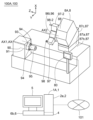
- FIG. 8 is a schematic perspective view showing the numerically controlled lathe according to the first embodiment.
- FIG. 9 is a block diagram showing an example of a hardware configuration of a control unit of a numerically controlled lathe.
- FIG. 10 is a diagram showing a schematic diagram of the positional relationship between the machine origin and the machining program origin in the machining program coordinate system.
- FIG. 11 is a block diagram showing an example of a hardware configuration of a control unit of a numerically controlled lathe.
- FIG. 12 is a diagram showing a schematic view of the offset amount displayed on the display device.
- FIG. 13 is a diagram showing a schematic view of a nail model setting window displayed on the display device.
- FIG. 14 is a diagram showing a schematic view of a workpiece model setting window displayed on the display device.
- FIG. 15 is a diagram showing a schematic view of a workpiece model creation window displayed on the display device.
- FIG. 16 is a diagram showing a typical state in which a chuck model setting window is displayed on the display device.
- FIG. 17 is a diagram that illustrates a schematic view of an assembly model in which a chuck model, a jaw model, and a workpiece model are combined and displayed on a display device.
- FIG. 18 is a diagram showing a schematic diagram of the positional relationship between the machine model origin and the program origin in the machining simulation coordinate system.
- FIG. 19 is a diagram showing a schematic diagram of the positional relationship between the machine model origin and the program origin in the machining simulation coordinate system.
- FIG. 20 is a diagram illustrating a schematic view of the second offset amount being displayed on the second display device.
- FIG. 21 is a diagram showing a schematic view of the first default data specifying the shape of the nail being displayed in an editable format on the second display device.
- FIG. 22 is a diagram typically showing a state in which a message recommending execution of the machining simulation again is displayed on the second display device.
- FIG. 23 is a diagram showing a schematic view of the second default data specifying the shape of the workpiece being displayed in an editable format on the second display device.
- FIG. 24 is a diagram typically showing a state in which a message recommending execution of the machining simulation again is displayed on the second display device.
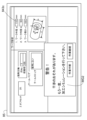
- FIG. 25 is a diagram illustrating a machine tool system according to the first embodiment.
- FIG. 21 is a diagram showing a schematic view of the first default data specifying the shape of the nail being displayed in an editable format on the second display device.
- FIG. 22 is a diagram typically showing a state in which
- FIG. 26 is a flowchart illustrating an example of a processing simulation method according to the first embodiment.
- FIG. 27 is a flowchart showing an example of a workpiece machining method in the first embodiment.
- FIG. 28 is a diagram illustrating an example of a non-volatile storage medium on which a program is recorded.
- machining simulation device 1 numerically controlled lathe 8
- machine tool system 100 machining simulation method, workpiece machining method, and program (more specifically, calculation program 41) in the embodiment will be described with reference to the drawings. Note that in the following description of the embodiment, parts and components having the same functions are given the same reference numerals, and repeated descriptions of parts and components given the same reference numerals will be omitted.
- FIG. 1 is a block diagram showing an example of a hardware configuration of the machining simulation device 1A in the first embodiment.
- FIG. 2 is a functional block diagram of a calculation device 2.
- FIG. 3 is a diagram showing a schematic view of a position of a machine origin G0 in a numerically controlled lathe.
- FIGS. 4 and 5 are diagrams showing a schematic view of a positional relationship between a machine model origin F0 and a program origin F1 in a machining simulation coordinate system.
- FIGS. 1 is a block diagram showing an example of a hardware configuration of the machining simulation device 1A in the first embodiment.
- FIG. 2 is a functional block diagram of a calculation device 2.
- FIG. 3 is a diagram showing a schematic view of a position of a machine origin G0 in a numerically controlled lathe.
- FIGS. 4 and 5 are diagrams showing a schematic view of a positional relationship between a machine model origin F0 and a program origin F1 in a machining simulation coordinate system
- FIG. 6 and 7 are diagrams showing a state in which a simulation image 50A is displayed on a display device 5.
- FIG. 8 is a schematic perspective view showing a numerically controlled lathe 8A in the first embodiment.
- FIG. 9 is a block diagram showing an example of a hardware configuration of a control unit 80 of the numerically controlled lathe 8A.
- FIG. 10 is a diagram showing a schematic view of a positional relationship between a machine origin G0 and a machining program origin G1 in a machining program coordinate system.
- FIG. 11 is a block diagram showing an example of a hardware configuration of a control unit 80 of the numerically controlled lathe 8A.
- FIG. 12 is a diagram showing a state where the offset amount T1 is displayed on the display device 5.
- FIG. 13 is a diagram showing a state where the setting window 50B of the claw model 94m is displayed on the display device 5.
- FIG. 14 is a diagram showing a state where the setting window 50C of the workpiece model 95m is displayed on the display device 5.
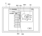
- FIG. 15 is a diagram showing a state where the workpiece model creation window 50D is displayed on the display device 5.
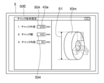
- FIG. 16 is a diagram showing a state where the setting window 50E of the chuck model 93m is displayed on the display device 5.
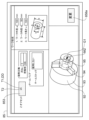
- FIG. 17 is a diagram showing a state where the assembly model 92m in which the chuck model 93m, the claw model 94m, and the workpiece model 95m are combined is displayed on the display device 5.
- FIG. 18 and 19 are diagrams showing a positional relationship between the machine model origin F0 and the program origin F1 in the machining simulation coordinate system.
- FIG. 20 is a diagram showing a state where the second offset amount T2 is displayed on the second display device 85.
- Fig. 21 is a diagram showing a state where the first default data DD1 specifying the shape of the claw 94 is displayed in an editable format on the second display device 85.
- Fig. 22 is a diagram showing a state where a message MG1 recommending to execute the machining simulation again is displayed on the second display device 85.
- Fig. 23 is a diagram showing a state where the second default data DD2 specifying the shape of the workpiece 95 is displayed in an editable format on the second display device 85.
- Fig. 24 is a diagram showing a state where a message MG2 recommending to execute the machining simulation again is displayed on the second display device 85.
- Fig. 25 is a diagram showing a machine tool system 100A in the first embodiment
- the machining simulation device 1A includes a calculation device 2 and a communication circuit 3. Additionally, the machining simulation device 1A may include a memory 4, a display device 5, and an input device 6. The input device 6 may be incorporated in the display device 5 (more specifically, the display device 5 may be a touch panel display 52 incorporating an input device 6a). Alternatively, or additionally, the machining simulation device 1A may include an input device 6b (e.g., a button, a switch, a lever, a pointing device, a keyboard, etc.) provided separately from the display device 5.
- an input device 6b e.g., a button, a switch, a lever, a pointing device, a keyboard, etc.
- the processing simulation device 1A may be configured by one computer. Alternatively, multiple computers may work together to function as the processing simulation device 1A. In other words, the processing simulation device 1A may include one computer, or may include multiple computers.
- the arithmetic unit 2 includes at least one processor 2a (e.g., at least one CPU).
- the memory 4 is a storage medium that can be read by the calculation device 2.
- the memory 4 may be, for example, a non-volatile or volatile semiconductor memory such as a RAM, a ROM, or a flash memory, or may be a magnetic disk or other type of memory.
- the memory 4 stores a calculation program 41 (e.g., a three-dimensional model creation program 41a, a program origin setting program 41b, a simulation calculation program 41c, and a display program 41d), a machining program 42 used to machine the workpiece 95 into a desired shape (more specifically, the machining program 42 to be executed by the numerically controlled lathe 8A to machine the workpiece 95 into a desired shape), and data 43 (e.g., first dimensional data 43a that specifies the shape of the chuck model, second dimensional data 43b that specifies the shape of the jaw model, third dimensional data 43c that specifies the shape of the workpiece model, position data 43e of the machine model origin, etc.).
- a calculation program 41 e.g., a three-dimensional model creation program 41a, a program origin setting program 41b, a simulation calculation program 41c, and a display program 41d
- a machining program 42 used to machine the workpiece 95 into a desired shape more specifically, the machining program 42 to be executed by
- the memory 4 may be distributed in multiple locations.
- the memory that stores the machining program 42 may be provided separately from the memory that stores the calculation program 41 or the data 43.
- a part of the memory 4 may be located at a position far from the communication circuit 3.
- the memory 4 may provide at least a part of the calculation program 41 or a part of the data 43 to the calculation device 2 via the communication circuit 3.
- At least a part of the data 43 may be input by an operator via the input device 6, and the input data 43 may be stored in the memory 4.
- at least a part of the data 43 may be transmitted from another computer to the machining simulation device 1A. In this case, the calculation device 2 stores the data 43 received via the communication circuit 3 in the memory 4.
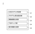
- the calculation device 2 may have a three-dimensional model creation unit 21, a program origin setting unit 22, a movement path generation unit 23, an interference check unit 24, and a display image generation unit 25. More specifically, the calculation device 2 may execute a calculation program 41 stored in the memory 4 to cause the calculation device 2 to function as the three-dimensional model creation unit 21, the program origin setting unit 22, the movement path generation unit 23, the interference check unit 24, and the display image generation unit 25.
- the machine origin G0 of the numerically controlled lathe 8A is the origin on the machine coordinate system of the numerically controlled lathe 8A.
- the machine origin G0 is a reference point of the numerically controlled lathe 8A that is independent of the shape of the workpiece 95.
- the machine coordinate system (X, Y, Z Cartesian coordinate system) of the numerically controlled lathe 8A is set based on the machine origin G0.
- the position of the machine origin G0 may be different for each numerically controlled lathe 8A. In other words, the position of the machine origin G0 is not limited to the position exemplified in FIG. 3.
- the claws 94 are attached to a chuck 93 of a numerically controlled lathe 8A.
- the chuck 93 is attached to a spindle 91 that rotates about a first axis AX1.
- the shape model of the claws 94 (hereinafter referred to as the "claw model 94m") has substantially the same shape as the claws 94 in the machining simulation coordinate system.
- the shape model of the chuck 93 (hereinafter referred to as the "chuck model 93m”) has substantially the same shape as the chuck 93 in the machining simulation coordinate system.
- the workpiece 95 is gripped by a plurality of jaws 94 attached to a chuck 93.
- the shape model of the workpiece 95 (hereinafter referred to as the "workpiece model 95m") has substantially the same shape as the workpiece 95 in the machining simulation coordinate system.
- the calculation device 2 executes the program origin setting program 41b to set the position of the program origin F1, which is the origin on the machining simulation coordinate system. More specifically, the calculation device 2 sets the position of the program origin F1 (see FIG. 4), which is the origin on the machining simulation coordinate system, based on the machine model origin F0 (see FIG. 4) on the machining simulation coordinate system corresponding to the machine origin G0 (see FIG. 3) of the numerically controlled lathe 8A, the above-mentioned claw model 94m, and the above-mentioned work model 95m.
- the machine model origin F0 is a point on the machining simulation coordinate system that simulates the machine origin G0 of the numerically controlled lathe 8A. It is preferable that the position data 43e of the machine model origin F0 is stored in advance in the memory 4.
- the distance from a preset reference surface 910m e.g., the tip surface 911m of the shape model 91m of the spindle 91
- the contact surface between the jaw model 94m and the base end surface 951m of the work model 95m is defined as distance L1.
- the distance from the base end surface 951m of the work model 95m to the tip surface 952m of the work model 95m is defined as distance L2.
- the distance from a preset reference surface 910m (e.g., the tip surface 911m of the shape model 91m of the spindle 91) to the machine model origin F0 is defined as distance L3.
- intersection point CP1 The distance between the machine model origin F0 and the program origin F1 in the direction along the rotation axis AT of the chuck model 93m is defined as distance L4. Furthermore, the intersection point between the rotation axis AT of the chuck model 93m and the first plane PL1 that passes through the machine model origin F0 and is perpendicular to the rotation axis AT is defined as intersection point CP1.
- the calculation device 2 can calculate the above-mentioned distance L1, for example, using the position data of the reference surface 910m stored in the memory 4, the first dimension data 43a stored in the memory 4 for specifying the shape of the chuck model 93m, and the second dimension data 43b stored in the memory 4 for specifying the shape of the jaw model 94m.
- the calculation device 2 can also calculate the above-mentioned distance L2, for example, using the position data of the reference surface 910m stored in the memory 4 and the position data 43e of the machine model origin F0 stored in the memory 4.
- the calculation of the distance L4 is performed using a model in which the bottom of the jaw model 94m and the base end surface 951m of the work model 95m are in contact with each other.
- the calculation device 2 (more specifically, the program origin setting unit 22) can set the position of the program origin F1 to a position moved a distance L4 along the above-mentioned rotation axis AT from the above-mentioned intersection CP1 toward the tip surface 952m of the work model 95m based on the machine model origin F0, the claw model 94m, and the work model 95m.
- the calculation device 2 can accurately set the position of the program origin F1 to a predetermined position of the work model (for example, the intersection CP2 between the above-mentioned rotation axis AT and the tip surface 952m of the work model) regardless of the diversity of the shapes of the claw model and the diversity of the shapes of the work model.
- a reference point G2 e.g., a reference workpiece origin
- a reference point F2 e.g., a reference workpiece model origin
- the position data of the reference point F2 may be stored in the memory 4.
- the reference point F2 (see FIG. 5) is a point in the machining simulation coordinate system that corresponds to the above-mentioned reference point G2 (see FIG. 3).
- the distance between the reference point F2 and the machine model origin F0 in the direction along the rotation axis AT is defined as distance L5.
- the distance between the reference point F2 and the program origin F1 in the direction along the rotation axis AT is defined as distance L6.
- intersection of the rotation axis AT and a second plane PL2 that passes through the reference point F2 and is perpendicular to the rotation axis AT is defined as intersection CP3.
- the calculation device 2 can calculate the above-mentioned distance L5 using the position data of the reference point F2 stored in the memory 4 and the position data 43e of the machine model origin F0.
- the calculation of the distance L6 is performed using a model in which the bottom of the claw model 94m and the base end surface 951m of the work model 95m are in contact with each other.
- the calculation device 2 (more specifically, the program origin setting unit 22) can set the position of the program origin F1 to a position moved a distance L6 along the above-mentioned rotation axis AT from the above-mentioned intersection CP3 toward the tip surface 952m of the work model 95m based on the machine model origin F0, the claw model 94m, and the work model 95m.
- the calculation device 2 can accurately set the position of the program origin F1 to a predetermined position of the work model (for example, the intersection CP2 between the above-mentioned rotation axis AT and the tip surface 952m of the work model) regardless of the diversity of shapes of the claw model and the diversity of shapes of the work model.
- the calculation device 2 sets a machining simulation coordinate system (e.g., an x, y, z Cartesian coordinate system) based on the program origin F1.
- a machining simulation coordinate system e.g., an x, y, z Cartesian coordinate system
- the calculation device 2 executes the machining program 42 using the program origin F1 as a reference position, thereby performing a machining simulation to virtually machine a workpiece model 95m, which is a shape model of the workpiece 95.
- the calculation device 2 executing the machining program 42 includes the calculation device 2 executing the machining program 42 via the calculation program 41 (more specifically, the simulation calculation program 41c).
- the calculation device 2 may process (in other words, interpret) the machining program 42 by executing the calculation program 41.
- the calculation device 2 may perform a machining simulation to virtually machine the workpiece model 95m based on the processing (in other words, based on the interpretation).
- the calculation device 2 may execute the machining program 42 via the simulation calculation program 41c stored in the memory 4, and may also execute the display program 41d stored in the memory 4 to display the simulation image 50A on the display device 5.
- the display program 41d may be a program separate from the simulation calculation program 41c, or may be a program incorporated into the simulation calculation program 41c.
- the numerically controlled lathe 8A includes a plurality of jaws 94 for gripping a workpiece 95, a chuck 93 for supporting the plurality of jaws 94, a spindle 91 for supporting the chuck 93 and rotating about a first axis AX1, a tool rest 96, a first tool holding unit 97 held by the tool rest 96, and a first tool 98 held by the first tool holding unit 97.
- the numerically controlled lathe 8A may also include another tool holding unit 97-2 held by the tool rest 96, and another tool 98-2 held by the other tool holding unit 97-2.
- the numerically controlled lathe 8A may also include a tailstock for pressing the tip surface of the workpiece 95.
- the simulation image 50A includes at least an image of a work model 95m corresponding to the workpiece 95, an image of a plurality of jaw models 94m corresponding to the plurality of jaws 94, an image of a tool rest model 96m corresponding to the tool rest 96, an image of a first tool holding unit model 97m corresponding to the first tool holding unit 97, and an image of a first tool model 98m corresponding to the first tool 98.
- the simulation image 50A may also include an image of another tool holding unit model 97m-2 corresponding to the other tool holding unit 97-2, and an image of another tool model 98m-2 corresponding to the other tool 98-2.
- the simulation image 50A may include an image of a tailstock model 99m corresponding to the tailstock.
- the calculation device 2 (more specifically, the movement path generating unit 23) executes the machining program 42 via the simulation calculation program 41c stored in the memory 4, thereby generating movement path data for the first tool model 98m in the machining simulation coordinate system with the program origin F1 as a reference.
- the calculation device 2 executes the simulation calculation program 41c and the display program 41d stored in the memory 4, thereby displaying, as a simulation image 50A, on the display device 5, a video in which the first tool model 98m and a plurality of models (96m, 97m, 97m-2, 98m-2) that move together with the first tool model 98m move relative to the workpiece model 95m along a path specified by the movement path data.
- the workpiece model 95m is simulated to be machined by the first tool model 98m.
- the calculation device 2 (more specifically, the interference check unit 24) executes the simulation calculation program 41c stored in the memory 4 to check for abnormal interference between the first tool model 98m, which moves along the path specified by the above-mentioned movement path data, and multiple models that move together with the first tool model 98m, and multiple other models (e.g., work model 95m, tailstock model 99m, etc.) in the machining simulation coordinate system.
- abnormal interference refers to interference between models that should not interfere with each other.
- abnormal interference includes (1) interference between the first tool holding unit model 97m attached to the tool rest model 96m and the workpiece model 95m, (2) interference between a tool holding unit model 97m-2 other than the first tool holding unit model 97m attached to the tool rest model 96m, or between a tool model 98m-2 other than the first tool model 98m, and the workpiece model 95m, and (3) interference between the tailstock model 99m and the first tool model 98m moving along a path specified by the above-mentioned movement path data, or multiple models moving together with the first tool model 98m, etc.
- the communication circuit 3 transmits data 43f indicating the position of the above-mentioned program origin F1 (see FIG. 4 or FIG. 5) set by the arithmetic unit 2 to the numerically controlled lathe 8A (see FIG. 8).
- the position of the program origin F1 which is the origin on the machining simulation coordinate system, is set based on the machine model origin F0, the claw model 94m, and the work model 95m.
- the position of the program origin F1 (see FIG. 4 or FIG. 5) relative to the machine model origin F0 can be accurately set on the machining simulation coordinate system. Therefore, a more accurate machining simulation can be performed based on the program origin F1 (see FIG. 6 or FIG. 7).
- the program origin F1 on the machining simulation coordinate system is accurately set, and data 43f indicating the position of the accurately set program origin F1 is transmitted to the numerically controlled lathe 8A.
- the numerically controlled lathe 8A can set the machining program origin using the program origin F1 on the machining simulation coordinate system. Therefore, in order to set the machining program origin, the work of actually measuring the reference position of the workpiece 95 is not necessary, or the work can be simplified.
- the reduction in the setup work performed at the machining site can further improve the operating rate of the numerically controlled lathe 8A.
- the workload of the operator at the machining site is further reduced.
- the energy consumption associated with the setup work is reduced, so the burden on the environment is also reduced.
- the processing simulation device 1A can be installed at the processing site, in an office, or even at the operator's home. When the processing simulation device 1A is installed outside the processing site, the operator's working environment is improved.
- part of the setup work is digitized, promoting DX (digital transformation).
- DX digital transformation
- the numerically controlled lathe 8A includes a control unit 80, a chuck 93, a jaw 94, a spindle 91, a rotary drive unit 90, and a moving unit 87 for moving a tool.
- the numerically controlled lathe 8A may include a tool rest 96 (e.g., a turret 96t) to which a tool holding unit for holding a tool is attached.
- the numerically controlled lathe 8A may include a second rotary drive unit 88 for rotating the turret 96t about a second axis AX2.
- the numerically controlled lathe 8A (more specifically, the tool rest 96) may also include a third rotary drive unit for rotating a tool about the tool axis.
- the chuck 93 supports the claws 94.
- the chuck 93 can move the claws 94 in a direction toward the rotation axis AX of the chuck 93, and can move the claws 94 in a direction away from the rotation axis AX.
- the multiple jaws 94 are attached to the chuck 93 and grip the workpiece 95.
- the spindle 91 supports the chuck 93.
- the spindle 91 also rotates around the first axis AX1 by the driving force of the rotation drive device 90.
- the rotation drive device 90 rotates the spindle 91 around the first axis AX1.
- the first axis AX1 is coaxial with the rotation axis AX of the chuck 93.
- the rotation drive device 90 rotates the spindle 91 around the first axis AX1, the spindle 91, the chuck 93, the multiple jaws 94, and the workpiece 95 rotate integrally around the first axis AX1.
- the moving device 87 moves a first tool 98 that processes the workpiece 95.
- the moving device 87 moves the first tool 98, a first tool holding unit 97 that holds the first tool 98, and a tool rest 96 (e.g., a turret 96t) that supports the first tool holding unit 97, one-dimensionally, two-dimensionally, or three-dimensionally.
- a tool rest 96 e.g., a turret 96t
- the moving device 87 may include a first moving device 87a that moves the tool rest 96 (e.g., turret 96t) in a direction perpendicular to the first axis AX1 and parallel to the horizontal plane (in other words, the Y-axis direction). Additionally, the moving device 87 may include a second moving device 87b that moves the tool rest 96 (e.g., turret 96t) in a direction parallel to the first axis AX1 (in other words, the Z-axis direction). The moving device 87 may also have a third moving device 87c that changes the height of the tool rest 96 (e.g., turret 96t).
- a first moving device 87a that moves the tool rest 96 (e.g., turret 96t) in a direction perpendicular to the first axis AX1 and parallel to the horizontal plane (in other words, the Y-axis direction).
- the moving device 87 may include a
- the control unit 80 controls the controlled devices. More specifically, the control unit 80 controls each of the multiple controlled devices (e.g., the rotation drive device 90, the moving device 87, the second rotation drive device 88, etc.) by transmitting a control command to each of the multiple controlled devices.
- the control unit 80 may be distributed and arranged in multiple locations. In other words, the control unit may be divided into multiple subunits that can communicate with each other.
- the numerically controlled lathe 8A (more specifically, the control unit 80) has a second arithmetic unit 82, a second communication circuit 83, a second memory 84, and a second display device 85. Additionally, the numerically controlled lathe 8A (more specifically, the control unit 80) may have a second input device 86.
- the second input device 86 may be incorporated in the second display device 85 (more specifically, the second display device 85 may be a touch panel display 852 incorporating the second input device 86).
- the numerically controlled lathe 8A may have a second input device (e.g., a button, a switch, a lever, a pointing device, a keyboard, etc.) provided separately from the second display device.
- the second calculation device 82, the second communication circuit 83, the second memory 84, the second display device 85 and/or the second input device 86 are connected to each other via a bus 81.
- the second calculation device 82 includes at least one processor 82a (e.g., at least one CPU).
- the second communication circuit 83 receives data 43f indicating the position of the program origin F1 from the machining simulation device 1A.
- the second memory 84 stores the data 43f indicating the position of the program origin F1 received by the second communication circuit 83.
- the machining simulation device 1A and the program origin F1 have already been explained in the explanation of the machining simulation device 1A in the first embodiment, so repeated explanations of the machining simulation device 1A and the program origin F1 will be omitted.
- the second memory 84 is a storage medium that can be read by the second calculation device 82.
- the second memory 84 may be, for example, a non-volatile or volatile semiconductor memory such as a RAM, a ROM, or a flash memory, or may be a magnetic disk or other type of memory.
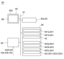
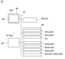
- the second memory 84 stores the calculation program 841, the machining program 42, and data 843 (for example, position data of the machine origin G0, dimensional data specifying the shape of the workpiece 95, etc.).
- the second memory 84 stores a processing calculation program 841a and a second display program 841b.
- the second memory 84 may be distributed across multiple locations.
- the memory that stores the processing program 42 may be provided separately from the memory that stores the calculation program 841 or the data 843.
- the second calculation device 82 sets the position of the machining program origin G1 (see FIG. 10) in the machining program coordinate system based on the position of the program origin F1. It is preferable that the second calculation device 82 sets the position of the machining program origin G1 described above so that the relative position of the machining program origin G1 with respect to the machine origin G0 in the machining program coordinate system (see FIG. 10) is equal to the relative position of the program origin F1 with respect to the machine model origin F0 in the machining simulation coordinate system (see FIG. 4 or FIG. 5).
- the second arithmetic device 82 executes the machining program 42 stored in the second memory 84 to determine the movement path of the first tool 98 in the machining program coordinate system with the machining program origin G1 as a reference.
- the execution of the machining program 42 by the second arithmetic device 82 includes the second arithmetic device 82 executing the machining program 42 via the machining operation program 841a.
- the second arithmetic device 82 may process (in other words, interpret) the machining program 42 by executing the machining operation program 841a.
- the second arithmetic device 82 may determine the movement path of the first tool 98 in the machining program coordinate system with the machining program origin G1 as a reference based on the processing (in other words, based on the interpretation).
- the second arithmetic device 82 generates a movement command 87i to be transmitted to the moving device 87 based on the movement path.
- the movement command 87i (see FIG. 11) generated by the second arithmetic device 82 is transmitted to the moving device 87.
- the second calculation device 82 generates a rotation command 90i by executing the machining program 42 (for example, by executing the machining program 42 via the machining calculation program 841a).
- the rotation command 90i (see FIG. 11) generated by the second calculation device 82 is transmitted to the rotation drive device 90.
- the rotary drive device 90 which receives the rotation command 90i, rotates the spindle 91, the chuck 93, the multiple jaws 94, and the workpiece 95 together around the first axis AX1.
- the movement device 87 which receives the movement command 87i, moves the first tool 98 along the movement path described above.
- the numerically controlled lathe 8A in the first embodiment receives data (e.g., data 43f indicating the position of the program origin F1) from a machining simulation device 1A that executes a high-precision machining simulation.
- data e.g., data 43f indicating the position of the program origin F1
- a machining simulation device 1A that executes a high-precision machining simulation.
- a machining program origin G1 is set in the machining program coordinate system based on the position of the program origin F1 that is accurately set by the machining simulation device 1A (see FIG. 10). Therefore, the task of actually measuring the reference position of the workpiece 95 in order to set the machining program origin is not necessary, or the task can be simplified. Furthermore, by reducing the amount of setup work performed at the machining site, the operating rate of the numerically controlled lathe 8A can be further improved. Furthermore, the workload of the operator at the machining site is further reduced. Furthermore, the energy consumption associated with the setup work is reduced, thereby reducing the burden on the environment.
- Machine tool system 100A Next, the machine tool system 100A in the first embodiment will be described.
- the machine tool system 100A in the first embodiment includes a machining simulation device 1A and a numerically controlled lathe 8A.
- the machining simulation device 1A and the numerically controlled lathe 8A are preferably connected to each other so as to be able to communicate with each other via a network 101.
- the network 101 may be an in-house network or may include an external network (e.g., the Internet).
- the machining simulation device 1A and the numerically controlled lathe 8A have already been explained, so repeated explanations of the machining simulation device 1A and the numerically controlled lathe 8A will be omitted.
- the calculation device 2 (more specifically, the program origin setting unit 22) may calculate an offset amount T1 indicating the relative position of the program origin F1.
- the offset amount T1 is the offset amount of the program origin F1 in the machining simulation coordinate system relative to a reference point F2 (e.g., a reference work model origin) whose position is fixed relative to the machine model origin F0 in the machining simulation coordinate system.
- the offset amount T1 is the offset amount in the z-axis direction (in other words, the direction along the rotation axis AT of the chuck model 93m) (i.e., the z-offset amount).
- the offset amount T1 may be the offset amount of the program origin F1 in the machining simulation coordinate system relative to the machine model origin F0 in the machining simulation coordinate system.
- the offset amount T1 is the offset amount in the z-axis direction (in other words, the direction along the rotation axis AT of the chuck model 93m) (i.e., the z-offset amount).
- the calculation device 2 executes the display program 41d stored in the memory 4 to cause the display device 5 to display the offset amount T1 described above.
- the operator can numerically confirm the relative position of the program origin F1.
- the calculation device 2 (more specifically, the display image generating unit 25) may execute the display program 41d stored in the memory 4 to cause the display device 5 to display the offset amount T1 in a format that can be edited by the operator.
- the operator can use the input device 6 to correct the position of the program origin F1 that was automatically set by the calculation device 2.
- the calculation device 2 may execute the display program 41d to simultaneously display on the display device 5 the above-mentioned offset amount T1, the claw model 94m, the work model 95m, and an image IM indicating the program origin F1.
- the operator can easily grasp the offset amount T1, the arrangement of the claw model 94m and the work model 95m, and the position of the program origin F1.
- the calculation device 2 executes the three-dimensional model creation program 41a and the display program 41d stored in the memory 4, thereby causing the display device 5 to display an assembly model 92m, which is a combination of a chuck model 93m, a jaw model 94m, and a workpiece model 95m, in a three-dimensional display format.
- the operator can easily intuitively grasp the original data used to derive the program origin F1 (or the offset amount T1).
- the machining simulation device 1A may transmit data indicating the offset amount T1 described above to the numerically controlled lathe 8A as data 43f indicating the position of the program origin F1 described above.
- the calculation device 2 (more specifically, the display image generating unit 25) executes the calculation program 41 (more specifically, the display program 41d) stored in the memory 4 to cause the display device 5 to display a setting window 50B for the nail model 94m. Note that when the previously used nail model 94m is to be used as is, the setting of the nail model 94m may be omitted.
- a specific nail model (hereinafter, referred to as specific nail model 94m-s) may be selected via the input device 6 from among a plurality of nail models 94m whose shapes have already been set, and the selected specific nail model 94m-s may be determined as the nail model 94m used to set the position of the program origin F1 described above.
- the arithmetic device 2 may execute the display program 41d stored in the memory 4 to cause the display device 5 to display the second dimension data 43b specifying the shape of the nail model 94m in a format that can be edited by the operator.
- the display device 5 may display an input field 501 in which the value of the second dimension data 43b is input in the setting window 50B.
- the arithmetic device 2 may execute the arithmetic program 41 (more specifically, the three-dimensional model creation program 41a and the display program 41d) stored in the memory 4 to simultaneously display the nail model 94m in a three-dimensional display format, the dimension line S2 added to the nail model 94m in the three-dimensional display format, and the input field 501 in which the length of the dimension line S2 is input.
- the arithmetic device 2 may automatically change the shape of the nail model 94m in the three-dimensional display format and the length of the dimension line S2 based on the value input in the input field 501, and automatically display the changed nail model 94m and the changed dimension line S2 on the display device 5.
- the calculation device 2 determines second dimensional data 43b that specifies the shape of the nail model 94m in response to data being input via the input device 6 for setting the nail model 94m, and stores the determined second dimensional data 43b in the memory 4.
- the calculation device 2 may acquire dimensional data of the nail model created using software such as CAD software via the communication circuit 3 or the like, convert the dimensional data into a format corresponding to the three-dimensional model creation program 41a or the like, and store the converted dimensional data in the memory 4 as second dimensional data 43b that specifies the shape of the nail model 94m.
- the arithmetic device 2 executes the arithmetic program 41 (more specifically, the display program 41d) stored in the memory 4 to display the setting window 50C of the workpiece model 95m on the display device 5.
- the arithmetic device 2 analyzes the machining program 42 to extract a workpiece model (hereinafter referred to as a "designated workpiece model") designated in the machining program 42.
- the arithmetic device 2 executes the display program 41d stored in the memory 4 to display the designated workpiece model on the display device 5 as a default model of the workpiece model 95m used to set the position of the above-mentioned program origin F1.
- the display device 5 may display the dimension data DT1 specifying the shape of the default model in a format that can be edited by the operator.
- the display device 5 may display an input field 502 for changing the value of the dimension data DT1 in the setting window 50C.
- the workpiece model 95m reflecting the change value is set.
- the default model is set as the workpiece model 95m as is.
- the calculation device 2 may execute the calculation program 41 (more specifically, the display program 41d) stored in the memory 4 to display the work model creation window 50D on the display device 5.
- the calculation device 2 executes the display program 41d stored in the memory 4 to display the third dimension data 43c that specifies the shape of the work model 95m in a format that can be edited by the operator.
- the display device 5 may display an input field 503 in which the value of the third dimension data 43c is input in the work model creation window 50D.
- the calculation device 2 may execute the calculation program 41 (more specifically, the three-dimensional model creation program 41a and the display program 41d) stored in the memory 4 to simultaneously display the work model 95m in a three-dimensional display format, the dimension line S3 added to the work model 95m in the three-dimensional display format, and the input field 503 in which the length of the dimension line S3 is input on the display device 5.
- the calculation device 2 may automatically change the shape of the work model 95m in a three-dimensional display format and the length of the dimension line S3 based on the value entered in the input field 503, and automatically display the changed work model 95m and the changed dimension line S3 on the display device 5.
- the calculation device 2 determines third dimensional data 43c that specifies the shape of the work model 95m in response to data being input via the input device 6 for setting the work model 95m, and stores the determined third dimensional data 43c in the memory 4.
- the calculation device 2 may acquire dimensional data of the work model created using software such as CAD software via the communication circuit 3 or the like, convert the dimensional data into a format corresponding to the three-dimensional model creation program 41a or the like, and store the converted dimensional data in the memory 4 as the third dimensional data 43c that specifies the shape of the work model 95m.
- the calculation device 2 (more specifically, the display image generating unit 25) executes the calculation program 41 (more specifically, the display program 41d) stored in the memory 4 to cause the display device 5 to display a setting window 50E for the chuck model 93m.
- the setting of the chuck model 93m may be omitted.
- the calculation device 2 executes the display program 41d stored in the memory 4 to cause the display device 5 to display the first dimension data 43a specifying the shape of the chuck model 93m in a format that can be edited by the operator.
- the display device 5 may display an input field 504 in which the value of the first dimension data 43a is input in the setting window 50E.
- the calculation device 2 may also execute the calculation program 41 (more specifically, the three-dimensional model creation program 41a and the display program 41d) stored in the memory 4 to simultaneously display the chuck model 93m in a three-dimensional display format, the dimension line S1 added to the chuck model 93m in the three-dimensional display format, and the input field 504 in which the length of the dimension line S1 is input, on the display device 5.
- the calculation device 2 may automatically change the shape of the chuck model 93m in a three-dimensional display format and the length of the dimension line S1 based on the value entered in the input field 504, and automatically display the changed chuck model 93m and the changed dimension line S1 on the display device 5.
- the calculation device 2 determines first dimensional data 43a that specifies the shape of the chuck model 93m in response to data being input via the input device 6 for setting the chuck model 93m, and stores the determined first dimensional data 43a in the memory 4.
- the calculation device 2 may acquire dimensional data of the chuck model created using software such as CAD software via the communication circuit 3 or the like, convert the dimensional data into a format corresponding to the three-dimensional model creation program 41a or the like, and store the converted dimensional data in the memory 4 as the first dimensional data 43a that specifies the shape of the chuck model 93m.
- the calculation device 2 executes the calculation program 41 (more specifically, the three-dimensional model creation program 41a) stored in the memory 4 to create an assembly model 92m that combines the chuck model 93m, the jaw model 94m, and the work model 95m, based on the set chuck model 93m, the set jaw model 94m, and the set work model 95m.
- the calculation device 2 (more specifically, the display image generation unit 25) also executes the calculation program 41 (more specifically, the display program 41d) stored in the memory 4 to display the created assembly model 92m on the display device 5.
- the shape of the chuck model 93m can be changed.
- the dimensional data of the chuck model 93m is used in addition to the dimensional data of the jaw model 94m and the dimensional data of the workpiece model 95m.
- the calculation device 2 (more specifically, the program origin setting unit 22) sets the position of the program origin F1, which is the origin on the machining simulation coordinate system, based on the machine model origin F0 on the machining simulation coordinate system corresponding to the machine origin G0 (see FIG. 3) of the numerically controlled lathe 8A, and the assembly model 92m (more specifically, the jaw model 94m, the workpiece model 95m, and the chuck model 93m).
- the distance from a preset reference surface 910m e.g., the tip surface 911m of the shape model 91m of the spindle 91
- the distance from the tip surface 931m of the chuck model 93m to the contact surface between the jaw model 94m and the base end surface 951m of the work model 95m is defined as distance L8.
- the calculation device 2 can calculate the above-mentioned distance L7 and distance L8, for example, using the position data of the reference surface 910m stored in the memory 4, the first dimension data 43a that specifies the shape of the chuck model 93m stored in the memory 4, and the second dimension data 43b that specifies the shape of the jaw model 94m stored in the memory 4.
- the calculation method for "distance L2" and "distance L3" has already been explained, so a repeated explanation of the calculation method for these distances will be omitted.
- the calculation of distance L4 is performed using a model in which the bottom of the jaw model 94m and the base end surface 951m of the work model 95m are in contact with each other.
- the calculation device 2 sets the position of the program origin F1 to a position moved a distance L4 along the rotation axis AT of the chuck model 93m from the intersection CP1 described above toward the tip surface 952m of the work model 95m. In this way, the calculation device 2 can accurately set the position of the program origin F1 to a predetermined position of the work model (for example, the intersection CP2 between the rotation axis AT and the tip surface 952m of the work model described above) regardless of the diversity of shapes of the jaw models, the diversity of shapes of the work model, and the diversity of shapes of the chuck model.
- a reference point G2 e.g., a reference workpiece origin
- a reference point F2 e.g., a reference workpiece model origin
- the position data of the reference point F2 may be stored in the memory 4.
- the reference point F2 is a point in the machining simulation coordinate system that corresponds to the above-mentioned reference point G2 (see FIG. 3).
- the calculation device 2 (more specifically, the program origin setting unit 22) can set the position of the program origin F1 to a position moved a distance L6 along the rotation axis AT of the chuck model 93m from the above-mentioned intersection CP3 toward the tip surface 952m of the work model 95m.
- the calculation device 2 can accurately set the position of the program origin F1 to a predetermined position of the work model (for example, the intersection CP2 between the above-mentioned rotation axis AT and the tip surface 952m of the work model) regardless of the diversity of shapes of the jaw models, the diversity of shapes of the work model, and the diversity of shapes of the chuck model.
- the calculation device 2 sets the position of the above-mentioned program origin F1 based on the machine model origin F0, the jaw model 94m, the workpiece model 95m, and the chuck model 93m. After the position of the program origin F1 is set, the calculation device 2 (more specifically, the movement path generation unit 23 and the interference check unit 24) uses the program origin F1 as a reference position to perform a machining simulation in which the workpiece model 95m is virtually machined. The operations and displays in the machining simulation have already been explained, so repeated explanations of these operations and displays will be omitted.
- the second communication circuit 83 of the numerically controlled lathe 8A receives data 43f indicating the position of the program origin F1 (e.g., data 430f indicating the offset amount T1 of the program origin F1) from the machining simulation device 1A.
- the second memory 84 stores the data 43f indicating the position of the program origin F1 received by the second communication circuit 83 (e.g., data 430f indicating the offset amount T1 of the program origin F1).
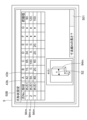
- the second calculation device 82 executes the second display program 841b stored in the second memory 84 to cause the second display device 85 to display the offset amount T1 of the program origin F1 (in other words, the offset amount T1 of the program origin F1 relative to the machine model origin F0 or a reference point F2 whose position is fixed relative to the machine model origin F0).
- the above-mentioned offset amount T1 functions as a default value for the offset amount (hereinafter referred to as the "second offset amount T2") of the machining program origin G1 relative to the machine origin G0 or a reference point G2 whose position is fixed relative to the machine origin G0 (see FIG. 3).
- FIG. 10 shows a schematic example of the second offset amount T2.
- the second offset amount T2 is the offset amount in the Z-axis direction (in other words, the direction along the rotation axis AX of the chuck 93) (i.e., the Z offset amount).
- the offset amount T1 set in the machining simulation device 1A functions as a default value for the second offset amount T2 set in the numerically controlled lathe 8A, so that the setting work of the second offset amount T2 in the numerically controlled lathe 8A is omitted or the setting work is simplified (for example, the second offset amount T2 can be set without actually measuring the reference position of the workpiece 95).
- the second calculation device 82 may execute the display program 41d stored in the memory 4 to cause the second display device 85 to display the above-mentioned offset amount T1 (in other words, the default value DD of the second offset amount) in a format that can be edited by the operator.
- the second display device 85 may display an input field 853 for changing the default value DD of the second offset amount T2 to another value.
- the second arithmetic unit 82 sets the position of the machining program origin G1 based on the second offset amount T2 and the machine origin G0 or a reference point G2 whose position is fixed relative to the machine origin G0 (see FIG. 10).
- the second arithmetic unit 82 also executes the machining program 42 stored in the second memory 84 (for example, by executing the machining program 42 via the machining arithmetic program 841a) to determine the movement path of the first tool 98 in the machining program coordinate system with the machining program origin G1 as a reference.
- the second arithmetic unit 82 also generates a movement command 87i to be transmitted to the movement device 87 based on the movement path.
- the movement command 87i (see FIG.
- the second arithmetic unit 82 also generates a rotation command 90i by executing the machining program 42 (for example, by executing the machining program 42 via the machining arithmetic program 841a).
- the rotation command 90i (see FIG. 11) generated by the second calculation device 82 is sent to the rotation drive device 90. In this way, the first tool 98 moves along the movement path, and the workpiece 95 is machined by the first tool 98.
- the second communication circuit 83 of the numerically controlled lathe 8A may receive the second dimension data 43b specifying the shape of the jaw model 94m and the third dimension data 43c specifying the shape of the workpiece model 95m from the machining simulation device 1A. Additionally, the second communication circuit 83 may receive the first dimension data 43a specifying the shape of the chuck model 93m from the machining simulation device 1A.
- the second memory 84 may store the second dimension data 43b, which specifies the shape of the claw model 94m and is received via the second communication circuit 83, as default data for the fifth dimension data 843b, which specifies the shape of the claw 94 (hereinafter referred to as "first default data DD1").
- the second memory 84 may store the third dimension data 43c, which specifies the shape of the workpiece model 95m and is received via the second communication circuit 83, as default data for the sixth dimension data 843c, which specifies the shape of the workpiece 95 (hereinafter referred to as "second default data DD2").
- the second memory 84 may also store the first dimension data 43a, which specifies the shape of the chuck model 93m and is received via the second communication circuit 83, as default data for the fourth dimension data 843a, which specifies the shape of the chuck 93 (hereinafter referred to as "third default data DD3").
- the second calculation device 82 may execute the second display program 841b stored in the second memory 84 to cause the second display device 85 to display an assembly 92, which is a combination of a chuck 93, jaws 94, and a workpiece 95, in a three-dimensional display format based on default data (DD1, DD2, DD3).
- the second display device 85 may simultaneously display a three-dimensional image of the assembly 92 and an image IM2 indicating a machining program origin G1, which will be described later.
- the second calculation device 82 executes the second display program 841b stored in the second memory 84 to cause the second display device 85 to display the first default data DD1 specifying the shape of the nail 94 in a format that can be edited by the operator.
- the second display device 85 may display an input field 854 for changing the value of the first default data DD1 to another value.
- a numerical value is entered into the input field 854, and the change operation unit 858b (more specifically, the change operation image displayed on the second display device 85) is operated, whereby the fifth dimension data 843b specifying the shape of the nail 94 is changed based on the numerical value entered into the input field 854.
- the second calculation device 82 may display a message MG1 on the second display device 85 recommending that the machining simulation be performed again in response to any value of the first default data DD1 being changed beyond a preset allowable value.
- the second calculation device 82 may display a message MG1 on the second display device 85 recommending that the machining simulation be performed again in response to the deviation amount of the shape of the claw 94 from the shape of the claw model 94m exceeding the allowable amount.
- the second calculation device 82 executes the second display program 841b stored in the second memory 84, thereby causing the second display device 85 to display the second default data DD2 specifying the shape of the workpiece 95 in a format that can be edited by the operator.
- the second display device 85 may display an input field 855 for changing the value of the second default data DD2 to another value.
- a numerical value is entered into the input field 855, and the change operation unit 858c (more specifically, the change operation image displayed on the second display device 85) is operated, whereby the sixth dimension data 843c specifying the shape of the workpiece 95 is changed based on the numerical value entered into the input field 855.
- the second calculation device 82 may display a message MG2 on the second display device 85 recommending that the machining simulation be performed again in response to any value of the second default data DD2 being changed beyond a preset allowable value.
- the second calculation device 82 may display a message MG2 on the second display device 85 recommending that the machining simulation be performed again in response to the deviation amount of the shape of the workpiece 95 from the shape of the workpiece model 95m exceeding the allowable amount.
- FIG. 26 is a flowchart showing an example of the processing simulation method according to the first embodiment.
- the machining simulation method in the first embodiment is executed using the machining simulation device 1A in the first embodiment or another machining simulation device.
- the machining simulation device 1A in the first embodiment has already been described, so a repeated description of the machining simulation device 1A in the first embodiment will be omitted.
- the first step ST1 is a first setting process.
- the first setting process includes the calculation device 2 of the machining simulation device 1 determining third dimension data 43c that specifies the shape of the workpiece model 95m, and the memory 4 storing the determined third dimension data 43c.
- the first setting step may include the calculation device 2 analyzing the machining program 42 to extract a work model 95m specified in the machining program 42, and the calculation device 2 determining third dimension data 43c that specifies the shape of the work model 95m based on the extracted work model 95m.
- the first setting step may include the calculation device 2 determining third dimension data 43c that specifies the shape of the work model 95m in response to input of data for setting the work model 95m via the input device 6.
- the first setting step may include the calculation device 2 reading out a previously created work model 95m from the memory 4, and the calculation device 2 determining third dimension data 43c that specifies the shape of the work model 95m based on the read work model 95m.
- the work model 95m may be displayed on the display device 5.
- displaying the work model 95m on the display device 5 may include displaying the third dimension data 43c that specifies the shape of the work model 95m on the display device 5 in a format that can be edited by the operator.
- the display device 5 simultaneously displays the work model 95m in a three-dimensional display format, the dimension line S3 added to the work model 95m in the three-dimensional display format, and an input field 503 in which the length of the dimension line S3 is input.
- the calculation device 2 automatically changes the shape of the work model 95m in the three-dimensional display format and the length of the dimension line S3 based on the value input in the input field 503, and automatically displays the changed work model 95m and the changed dimension line S3 on the display device 5.
- the second step ST2 is a second setting process.
- the second setting process includes the calculation device 2 determining second dimensional data 43b that specifies the shape of the nail model 94m, and the memory 4 storing the determined second dimensional data 43b.
- the second setting step may include the calculation device 2 determining second dimensional data 43b that specifies the shape of the nail model 94m in response to input of data for setting the nail model 94m via the input device 6.
- the second setting step may include the calculation device 2 reading out a nail model 94m created in the past from the memory 4, and the calculation device 2 determining second dimensional data 43b that specifies the shape of the nail model 94m based on the read nail model 94m.
- the nail model 94m may be displayed on the display device 5.
- displaying the nail model 94m on the display device 5 may include displaying the second dimension data 43b specifying the shape of the nail model 94m on the display device 5 in a format that can be edited by the operator.
- the display device 5 simultaneously displays the nail model 94m in a three-dimensional display format, the dimension line S2 added to the nail model 94m in the three-dimensional display format, and an input field 501 in which the length of the dimension line S2 is input.
- the calculation device 2 automatically changes the shape of the nail model 94m in the three-dimensional display format and the length of the dimension line S2 based on the value input in the input field 501, and automatically displays the changed nail model 94m and the changed dimension line S2 on the display device 5.
- the second step ST2 may be performed after the first step ST1 or before the first step ST1.
- the third step ST3 is a third setting process.
- the third setting process includes the calculation device 2 determining first dimension data 43a that specifies the shape of the chuck model 93m, and the memory 4 storing the determined first dimension data 43a.
- the third setting step may include the calculation device 2 determining first dimensional data 43a that specifies the shape of the chuck model 93m in response to input of data for setting the chuck model 93m via the input device 6.
- the third setting step may include the calculation device 2 reading out a previously created chuck model 93m from the memory 4, and the calculation device 2 determining first dimensional data 43a that specifies the shape of the chuck model 93m based on the read chuck model 93m.
- the chuck model 93m may be displayed on the display device 5.
- displaying the chuck model 93m on the display device 5 may include displaying the first dimension data 43a specifying the shape of the chuck model 93m on the display device 5 in a format that can be edited by the operator.
- the display device 5 simultaneously displays the chuck model 93m in a three-dimensional display format, the dimension line S1 added to the chuck model 93m in the three-dimensional display format, and an input field 504 in which the length of the dimension line S1 is input.
- the calculation device 2 automatically changes the shape of the chuck model 93m in the three-dimensional display format and the length of the dimension line S1 based on the value input in the input field 504, and automatically displays the changed chuck model 93m and the changed dimension line S1 on the display device 5.
- the third step ST3 may be performed after the first step ST1 and the second step ST2, or before the first step ST1 and the second step ST2. Alternatively, the third step ST3 may be performed between the first step ST1 and the second step ST2. Note that the third step ST3 may be omitted.
- a fourth step ST4 the calculation device 2 creates an assembly model 92m that combines the work model 95m, the jaw model 94m, and the chuck model 93m.
- the fourth step ST4 is an assembly model creation process.
- the assembly model creation process preferably includes checking whether the created assembly model 92m is normal (in other words, a check process).
- the check process includes, for example, checking whether the jaw model 94m has a shape suitable for gripping the work model 95m. If the assembly model 92m is not normal, the calculation device 2 may cause the display device 5 to display an alert.
- the assembly model 92m created by the assembly model creation process may be displayed on the display device 5.
- the fifth step ST5 is a program origin setting process.
- the program origin setting process may be configured to be automatically executed by the computing device 2 by operating the origin setting operation unit 55 (more specifically, the origin setting operation unit 55a displayed on the display device 5).
- the calculation device 2 sets the position of the program origin F1, which is the origin on the machining simulation coordinate system, based on the machine model origin F0 on the machining simulation coordinate system corresponding to the machine origin G0 of the numerically controlled lathe 8, the claw model 94m, which is a shape model of the claw 94 attached to the chuck 93 of the numerically controlled lathe 8, and the workpiece model 95m, which is a shape model of the workpiece 95 gripped by the multiple claws 94.
- the calculation device 2 sets the position of the program origin F1 taking into consideration the shape of the chuck model 93m. More specifically, as illustrated in FIG. 18 or FIG. 19, in the program origin setting step, the calculation device 2 sets the position of the program origin F1, which is the origin on the machining simulation coordinate system, based on the above-mentioned machine model origin F0, the above-mentioned jaw model 94m, the above-mentioned workpiece model 95m, and the chuck model 93m.
- the program origin setting step (fifth step ST5) preferably includes storing data 43f indicating the position of the program origin F1 set by the calculation device 2 in the memory 4.
- the data 43f indicating the position of the program origin F1 may be data indicating the offset amount T1 of the program origin F1 with respect to the machine model origin F0 or a reference point F2 whose position is fixed with respect to the machine model origin F0.
- the sixth step ST6 is a display step.
- the display step may include simultaneously displaying the above-mentioned offset amount T1, the claw model 94m in a three-dimensional display format, the workpiece model 95m in a three-dimensional display format, and an image IM indicating the program origin F1 on the display device 5.
- the display step may also include displaying the above-mentioned offset amount T1 on the display device 5 in a format that can be edited by the operator.
- the display step (sixth step ST6) may be omitted.
- the seventh step ST7 a machining simulation is performed to virtually machine the workpiece model 95m.
- the seventh step ST7 is a machining simulation execution process.
- the machining simulation execution process includes the calculation device 2 (more specifically, the movement path generation unit 23 and the interference check unit 24) performing a machining simulation to virtually machine the workpiece model 95m by executing the machining program 42 using the program origin F1 as a reference position.
- the machining simulation execution process includes the calculation device 2 generating movement path data for the first tool model 98m that simulates machining of the workpiece model 95m in the machining simulation coordinate system, based on the program origin F1.
- the machining simulation execution process may include displaying on the display device 5 a video in which the first tool model 98m and a number of models (96m, 97m, 97m-2, 98m-2) moving together with the first tool model 98m move relative to the workpiece model 95m along a path specified by the above-mentioned movement path data.
- the workpiece model 95m is simulated to be machined by the first tool model 98m.
- the machining simulation execution process may include the calculation device 2 checking whether or not there is abnormal interference between the first tool model 98m and a plurality of models that move together with the first tool model 98m, and a plurality of other models (e.g., the work model 95m, the tailstock model 99m, etc.).
- the machining simulation execution process may also include displaying a message indicating that there is abnormal interference on the display device 5 when the calculation device 2 determines that there is abnormal interference.
- step ST8 data (43a, 43b, 43c, 43f) is transmitted from the communication circuit 3 of the machining simulation device 1 to the numerically controlled lathe 8.
- the tenth step ST10 is a data transmission process.
- the data transmission process includes transmitting data 43f (for example, the offset amount T1 described above) indicating the position of the program origin F1, which is the origin on the machining simulation coordinate system, from the communication circuit 3 of the machining simulation device 1 to the numerically controlled lathe 8.
- data 43f for example, the offset amount T1 described above
- the data transmission process may include transmitting second dimension data 43b specifying the shape of the jaw model 94m and third dimension data 43c specifying the shape of the workpiece model 95m from the communication circuit 3 of the machining simulation device 1 to the numerically controlled lathe 8.
- the data transmission process may also include transmitting first dimension data 43a specifying the shape of the chuck model 93m from the communication circuit 3 of the machining simulation device 1 to the numerically controlled lathe 8.
- the data transmission process may also include transmitting execution result data of the machining simulation (e.g., data indicating that no abnormal interference occurred in the machining simulation) from the communication circuit 3 of the machining simulation device 1 to the numerically controlled lathe 8.
- execution result data of the machining simulation e.g., data indicating that no abnormal interference occurred in the machining simulation
- the calculation program 41 in the first embodiment is a program for causing the processing simulation device 1 to execute the processing simulation method in the first embodiment.
- the program in the first embodiment includes the steps of: (1) setting the position of the program origin F1, which is the origin on the machining simulation coordinate system, based on a machine model origin F0 on the machining simulation coordinate system corresponding to the machine origin G0 of the numerically controlled lathe 8, a claw model 94m which is a shape model of the claw 94 attached to the chuck 93 of the numerically controlled lathe 8, and a workpiece model 95m which is a shape model of the workpiece 95 gripped by the multiple claws 94 (in other words, the above-mentioned fifth step ST5); and (2) setting the position of the program origin F1, which is the origin on the machining simulation coordinate system, based on the program origin F1.
- a machining simulation method that includes a process of performing a machining simulation in which the workpiece model 95m is virtually machined by executing the machining program 42 using the program origin F1 as a reference position (e.g., by interpreting the machining program 42 using the program origin F1 as a reference position) (in other words, the seventh step ST7 described above); and (3) a process
- the program in the first embodiment may be a program for causing the processing simulation device 1 to execute the processing simulation method including the above-mentioned first setting step (first step ST1) and/or the above-mentioned second setting step (second step ST2).
- the program in the first embodiment may be a program for causing the processing simulation device 1 to execute the processing simulation method including the above-mentioned third setting step (third step ST3).
- the program in the first embodiment may be a program for causing the processing simulation device 1 to execute the processing simulation method including the above-mentioned assembly model creation step (fourth step ST4).
- the program in the first embodiment may be a program for causing the processing simulation device 1 to execute the processing simulation method including the above-mentioned display step (sixth step ST6).
- the program (more specifically, the calculation program 41) may be a program for causing the machining simulation device 1 to execute a machining simulation method including the steps of: (1) simultaneously displaying, on the display device 5, a nail model 94m in a three-dimensional display format, a dimension line S2 added to the nail model 94m in a three-dimensional display format, and an input field 501 in which the length of the dimension line S2 is input; and (2) automatically changing the shape of the nail model 94m in a three-dimensional display format and the length of the dimension line S2 based on the value input into the input field 501, and automatically displaying the changed nail model 94m and the changed dimension line S2 on the display device 5.
- the memory 4 in the first embodiment may be a non-volatile storage medium on which the above-mentioned program (more specifically, the calculation program 41) is recorded.
- the non-volatile storage medium on which the above-mentioned program (more specifically, the calculation program 41) is recorded may be a portable storage medium 4M, as exemplified in FIG. 28.
- the machining simulation method and program (more specifically, the calculation program 41) in the first embodiment, or the non-volatile storage medium on which the program (more specifically, the calculation program 41) is recorded, achieves the same effects as the machining simulation device 1A in the first embodiment.
- FIG. 26 and 27 are flow charts showing an example of the workpiece machining method in the first embodiment.
- the workpiece machining method in the first embodiment is performed using the machine tool system 100A in the first embodiment or another machine tool system.
- the machine tool system 100A in the first embodiment (more specifically, the machining simulation device 1A and the numerically controlled lathe 8A) have already been described, so a repeated description of the machine tool system 100A in the first embodiment will be omitted.
- the workpiece machining method in the first embodiment includes: (1) a step of setting the position of a program origin F1, which is the origin on the machining simulation coordinate system, based on a machine model origin F0 on the machining simulation coordinate system corresponding to a machine origin G0 of the numerically controlled lathe 8, a claw model 94m which is a shape model of a claw 94 attached to a chuck 93 of the numerically controlled lathe 8, and a workpiece model 95m which is a shape model of a workpiece 95 gripped by the multiple claws 94 (in other words, the above-mentioned fifth step ST5); and (2) a step of setting the position of a program origin F1, which is the origin on the machining simulation coordinate system, based on the machine model origin F0 on the machining simulation coordinate system corresponding to a machine origin G0 of the numerically controlled lathe 8, a claw model 94m which is a shape model of a claw 94 attached to a chuck 93 of the numerically controlled lathe 8, and a work
- the workpiece machining method in the first embodiment may include the above-mentioned first setting step (first step ST1) and/or the above-mentioned second setting step (second step ST2). Alternatively, or additionally, the workpiece machining method in the first embodiment may include the above-mentioned third setting step (third step ST3). Alternatively, or additionally, the workpiece machining method in the first embodiment may include the above-mentioned assembly model creation step (fourth step ST4). Alternatively, or additionally, the workpiece machining method in the first embodiment may include the above-mentioned display step (sixth step ST6). Also, the workpiece machining method in the first embodiment may include the above-mentioned data transmission step (eighth step ST8).
- the first step ST1 to the eighth step ST8 have already been explained in the machining simulation method of the first embodiment, so repeated explanations of the first step ST1 to the eighth step ST8 will be omitted.
- the second communication circuit 83 of the numerically controlled lathe 8 receives data (43a, 43b, 43c, 43f) from the machining simulation device 1.
- the ninth step ST9 is a data receiving process.
- the data receiving process includes the second communication circuit 83 of the numerically controlled lathe 8 receiving data 43f indicating the position of the program origin F1, which is the origin on the machining simulation coordinate system, from the machining simulation device 1 (for example, data 430f indicating the offset amount T1 described above).
- the data receiving process may include the second communication circuit 83 of the numerically controlled lathe 8 receiving, from the machining simulation device 1, second dimensional data 43b specifying the shape of the jaw model 94m and third dimensional data 43c specifying the shape of the workpiece model 95m.
- the data receiving process may also include the second communication circuit 83 of the numerically controlled lathe 8 receiving, from the machining simulation device 1, first dimensional data 43a specifying the shape of the chuck model 93m.
- the data receiving process may also include the second communication circuit 83 of the numerically controlled lathe 8 receiving execution result data of the machining simulation (e.g., data indicating that there was no abnormal interference in the machining simulation) from the machining simulation device 1.
- execution result data of the machining simulation e.g., data indicating that there was no abnormal interference in the machining simulation
- the data (43a, 43b, 43c, 43f, 430f) received via the second communication circuit 83 is stored in the second memory 84.
- data 43f indicating the position of the program origin F1 (more specifically, data 430f indicating the offset amount T1 described above) is stored in the second memory 84.
- first dimensional data 43a specifying the shape of the chuck model 93m, second dimensional data 43b specifying the shape of the jaw model 94m, and third dimensional data 43c specifying the shape of the work model 95m are stored in the second memory 84.
- the offset amount T1 described above is displayed on the second display device 85.
- the tenth step ST10 is the second display step.
- the second display step includes displaying, on the second display device 85, the offset amount T1 of the program origin F1 relative to the machine model origin F0 or a reference point F2 whose position is fixed relative to the machine model origin F0.
- the offset amount T1 described above functions as a default value DD of the second offset amount T2, which is the offset amount of the machining program origin G1 relative to the machine origin G0 or a reference point G2 (see FIG. 10) whose position is fixed relative to the machine origin G0.
- the offset amount T1 set in the machining simulation device 1 functions as the default value DD of the second offset amount T2 set in the numerically controlled lathe 8, so that the setting work of the second offset amount T2 in the numerically controlled lathe 8 is omitted or the setting work is simplified (for example, the second offset amount T2 can be set without actually measuring the reference position of the workpiece 95).
- the second display step may include displaying the above-mentioned offset amount T1 (in other words, the default value DD of the above-mentioned second offset amount T2) on the second display device 85 in a format that can be edited by the operator.
- the second display step may include displaying a message on the second display device 85 recommending that the machining simulation be performed again in response to the default value DD being changed beyond a preset allowable value.
- the dimension data (more specifically, the fifth dimension data 843b) specifying the shape of the nail 94 is displayed on the second display device 85.
- the eleventh step ST11 is the third display step.
- the second display device 85 may display data specifying the shape of the nail model 94m as the first default data DD1 of the fifth dimension data 843b.
- the second display device 85 may display the first default data DD1 in a format that can be edited by the operator. More specifically, the second display device 85 may display an input field 854 for changing the value of the first default data DD1 to another value.
- the fifth dimension data 843b displayed on the second display device 85 may be changed based on the numerical value input in the input field 854 by inputting a numerical value in the input field 854 and operating the change operation unit 858b.
- the third display step may include displaying a message MG1 on the second display device 85 recommending that the machining simulation be performed again in response to any value of the first default data DD1 being changed beyond a preset allowable value.
- the dimension data (more specifically, the sixth dimension data 843c) specifying the shape of the workpiece 95 is displayed on the second display device 85.
- the twelfth step ST12 is the fourth display step.
- the second display device 85 may display data specifying the shape of the workpiece model 95m as the second default data DD2 of the sixth dimension data 843c.
- the second display device 85 may display the second default data DD2 in a format that can be edited by the operator. More specifically, the second display device 85 may display an input field 855 for changing the value of the second default data DD2 to another value.
- the sixth dimension data 843c displayed on the second display device 85 may be changed based on the numerical value entered in the input field 855 by entering a numerical value in the input field 855 and operating the change operation unit 858c.
- the fourth display step may include displaying a message MG2 on the second display device 85 recommending that the machining simulation be performed again in response to any value of the second default data DD2 being changed beyond a preset allowable value.
- the tenth step ST10 to the twelfth step ST12 may be performed in any order. Furthermore, the tenth step ST10 and the twelfth step ST12 may be performed simultaneously, or the eleventh step ST11 and the twelfth step ST12 may be performed simultaneously. Furthermore, each of the tenth step ST10 to the twelfth step ST12 may be omitted.
- step ST13 the position of the machining program origin G1 in the machining program coordinate system is set based on the position of the program origin F1.
- Step ST13 is a machining program origin setting process.
- the machining program origin setting process includes the second calculation device 82 setting the position of the machining program origin G1 so that the relative position of the machining program origin G1 with respect to the machine origin G0 in the machining program coordinate system is equal to the relative position of the program origin F1 with respect to the machine model origin F0 (see FIG. 4, FIG. 5, FIG. 18, or FIG. 19).
- the machining program origin setting step may include the second calculation device 82 setting the position of the machining program origin G1 so that the second offset amount T2 of the machining program origin G1 with respect to the machine origin G0 or a reference point G2 whose position is fixed with respect to the machine origin G0 is equal to the above-mentioned offset amount T1. Furthermore, if the second offset amount T2 is corrected in the tenth step ST10, the machining program origin setting step may include correcting the position of the machining program origin G1 based on the difference between the second offset amount T2 after correction and the second offset amount T2 before correction.
- step ST14 the workpiece 95 is machined by the numerically controlled lathe 8, which executes the machining program 42 using the machining program origin G1 as a reference position.
- Step ST14 is a machining process.
- the machining process includes determining the movement path of the first tool 98 based on the machining program origin G1.
- the machining process also includes the second calculation device 82 sending a control command to each of a plurality of controlled devices (e.g., the movement device 87, the rotary drive device 90, etc.).
- the machining process includes: (1) the second arithmetic unit 82 generating a movement command 87i based on a movement path of the first tool 98 determined with reference to the machining program origin G1; (2) the second arithmetic unit 82 transmitting the movement command 87i to the movement device 87; and (3) the movement device 87 receiving the movement command 87i moving the first tool 98 along the movement path.
- the machining process also includes: (4) the second arithmetic unit 82 transmitting a rotation command 90i to the rotation drive device 90; and (5) the rotation drive device 90 receiving the rotation command 90i rotating the spindle 91, the chuck 93, the multiple jaws 94, and the workpiece 95 together around the first axis AX1.
- a highly accurate machining simulation is performed in advance.
- a highly accurate machining simulation it is possible to omit or simplify the interference check performed using the numerically controlled lathe 8.
- By omitting or simplifying the interference check at the machining site it is possible to improve the operating rate of the numerically controlled lathe 8. In addition, the workload of the operator at the machining site is reduced.
- the machining program origin G1 in the machining program coordinate system is set based on the position of the program origin F1, which is the origin on the machining simulation coordinate system that is accurately set in the machining simulation. Therefore, the task of actually measuring the reference position of the workpiece 95 in order to set the machining program origin is not necessary, or the task can be simplified.
- the operating rate of the numerically controlled lathe 8A can be further improved.
- the workload of the operator at the machining site is further reduced.
- the burden on the environment is also reduced because the energy consumption associated with the setup work is reduced.
Landscapes
- Engineering & Computer Science (AREA)
- Mechanical Engineering (AREA)
- Human Computer Interaction (AREA)
- Manufacturing & Machinery (AREA)
- Physics & Mathematics (AREA)
- General Physics & Mathematics (AREA)
- Automation & Control Theory (AREA)
- Numerical Control (AREA)
Abstract
加工シミュレーション装置は、演算装置と、通信回路とを具備する。演算装置は、数値制御旋盤の機械原点に対応する加工シミュレーション座標系上の機械モデル原点と、数値制御旋盤のチャックに取り付けられる爪の形状モデルである爪モデルと、複数の爪によって把持されるワークの形状モデルであるワークモデルとに基づいて、加工シミュレーション座標系上の原点であるプログラム原点の位置を設定する。また、演算装置は、プログラム原点を基準位置として用いて加工プログラムを実行することにより、ワークモデルを仮想的に加工する加工シミュレーションを行う。通信回路は、プログラム原点の位置を示すデータを、数値制御旋盤に送信する。
Description
本発明は、加工シミュレーション装置、数値制御旋盤、工作機械システム、ワーク加工方法、および、プログラムに関する。
旋盤を用いてワークを加工する技術が知られている。
関連する技術として、特許文献1には、加工シミュレーション装置が開示されている。特許文献1に記載の加工シミュレーション装置は、加工プログラムに基づいて工具と加工物の相対運動をシミュレーションする加工シミュレーション手段と、工具と加工物の三次元モデルを識別子と共に保存するメモリと、加工プログラム中に指定された三次元モデルの識別子を読み取る手段と、読み取った識別子と一致する識別子の三次元モデルをメモリから呼び出して加工シミュレーション手段に設定する手段と、を具備する。特許文献1に記載の加工シミュレーション装置では、加工物形状の原点が、仮想三次元空間の原点(X=0、Y=0、Z=0)に設定される。
本発明の目的は、加工シミュレーション座標系上のプログラム原点を的確に設定することが可能な加工シミュレーション装置、数値制御旋盤、工作機械システム、ワーク加工方法、および、プログラムを提供することである。
いくつかの実施形態における加工シミュレーション装置は、数値制御旋盤の機械原点に対応する加工シミュレーション座標系上の機械モデル原点と、前記数値制御旋盤のチャックに取り付けられる爪の形状モデルである爪モデルと、複数の前記爪によって把持されるワークの形状モデルであるワークモデルとに基づいて、加工シミュレーション座標系上の原点であるプログラム原点の位置を設定し、前記プログラム原点を基準位置として用いて加工プログラムを実行することにより、前記ワークモデルを仮想的に加工する加工シミュレーションを行う演算装置と、前記プログラム原点の前記位置を示すデータを、前記数値制御旋盤に送信する通信回路と、を具備する。
いくつかの実施形態における数値制御旋盤は、数値制御旋盤の機械原点に対応する加工シミュレーション座標系上の機械モデル原点と、前記数値制御旋盤のチャックに取り付けられる爪の形状モデルである爪モデルと、複数の前記爪によって把持されるワークの形状モデルであるワークモデルとに基づいて、加工シミュレーション座標系上の原点であるプログラム原点の位置を設定し、前記プログラム原点を基準位置として用いて加工プログラムを実行することにより、前記ワークモデルを仮想的に加工する加工シミュレーションを行う加工シミュレーション装置から、前記プログラム原点の前記位置を示すデータを受信する第2通信回路と、前記加工プログラムを記憶する第2メモリと、前記チャックと、前記チャックに取り付けられ、前記ワークを把持する複数の前記爪と、前記チャックを支持するスピンドルと、前記スピンドルを第1軸まわりに回転させる回転駆動装置と、第1工具を移動させる移動装置と、前記プログラム原点の前記位置に基づいて、加工プログラム座標系において加工プログラム原点の位置を設定し、前記加工プログラムを実行することにより、前記加工プログラム原点を基準として、前記第1工具の移動経路を決定する第2演算装置と、を具備する。
いくつかの実施形態における工作機械システムは、上述の加工シミュレーション装置と、上述の数値制御旋盤とを具備する。
いくつかの実施形態におけるワーク加工方法は、数値制御旋盤の機械原点に対応する加工シミュレーション座標系上の機械モデル原点と、前記数値制御旋盤のチャックに取り付けられる爪の形状モデルである爪モデルと、複数の前記爪によって把持されるワークの形状モデルであるワークモデルとに基づいて、加工シミュレーション座標系上の原点であるプログラム原点の位置を設定する工程と、前記プログラム原点を基準位置として用いて加工プログラムを実行することにより、前記ワークモデルを仮想的に加工する加工シミュレーションを行う工程と、前記プログラム原点の前記位置に基づいて、加工プログラム座標系における加工プログラム原点の位置を設定する工程と、前記加工プログラム原点を基準位置として用いて前記加工プログラムを実行する前記数値制御旋盤によって、前記ワークを加工する工程と、を具備する。
いくつかの実施形態におけるプログラムは、数値制御旋盤の機械原点に対応する加工シミュレーション座標系上の機械モデル原点と、前記数値制御旋盤のチャックに取り付けられる爪の形状モデルである爪モデルと、複数の前記爪によって把持されるワークの形状モデルであるワークモデルとに基づいて、加工シミュレーション座標系上の原点であるプログラム原点の位置を設定する工程と、前記プログラム原点を基準位置として用いて加工プログラムを実行することにより、前記ワークモデルを仮想的に加工する加工シミュレーションを行う工程と、前記プログラム原点の前記位置を示すデータを、前記数値制御旋盤に送信する工程と、を具備する加工シミュレーション方法を加工シミュレーション装置に実行させるためのプログラムである。
本発明により、加工シミュレーション座標系上のプログラム原点を的確に設定することが可能な加工シミュレーション装置、数値制御旋盤、工作機械システム、ワーク加工方法、および、プログラムを提供することができる。
以下、図面を参照して、実施形態における加工シミュレーション装置1、数値制御旋盤8、工作機械システム100、加工シミュレーション方法、ワーク加工方法、および、プログラム(より具体的には、演算プログラム41)について説明する。なお、以下の実施形態の説明において、同一の機能を有する部位、部材については同一の符号を付し、同一の符号が付された部位、部材についての繰り返しとなる説明は省略する。
(第1の実施形態)
図1乃至図25を参照して、第1の実施形態における加工シミュレーション装置1A、数値制御旋盤8A、および、工作機械システム100Aについて説明する。図1は、第1の実施形態における加工シミュレーション装置1Aのハードウェア構成の一例を示すブロック図である。図2は、演算装置2の機能ブロック図である。図3は、数値制御旋盤における機械原点G0の位置を模式的に示す図である。図4および図5は、加工シミュレーション座標系において、機械モデル原点F0とプログラム原点F1との間の位置関係を模式的に示す図である。図6および図7は、表示装置5にシミュレーション画像50Aが表示されている様子を模式的に示す図である。図8は、第1の実施形態における数値制御旋盤8Aを模式的に示す概略斜視図である。図9は、数値制御旋盤8Aの制御ユニット80のハードウェア構成の一例を示すブロック図である。図10は、加工プログラム座標系において、機械原点G0と加工プログラム原点G1との間の位置関係を模式的に示す図である。図11は、数値制御旋盤8Aの制御ユニット80のハードウェア構成の一例を示すブロック図である。図12は、表示装置5にオフセット量T1が表示されている様子を模式的に示す図である。図13は、表示装置5に、爪モデル94mの設定ウィンドウ50Bが表示されている様子を模式的に示す図である。図14は、表示装置5に、ワークモデル95mの設定ウィンドウ50Cが表示されている様子を模式的に示す図である。図15は、表示装置5に、ワークモデル作成ウィンドウ50Dが表示されている様子を模式的に示す図である。図16は、表示装置5に、チャックモデル93mの設定ウィンドウ50Eが表示されている様子を模式的に示す図である。図17は、表示装置5に、チャックモデル93mと、爪モデル94mと、ワークモデル95mとが組み合わせられたアセンブリモデル92mが表示されている様子を模式的に示す図である。図18および図19は、加工シミュレーション座標系において、機械モデル原点F0とプログラム原点F1との間の位置関係を模式的に示す図である。図20は、第2表示装置85に第2オフセット量T2が表示されている様子を模式的に示す図である。図21は、第2表示装置85に、爪94の形状を特定する第1デフォルトデータDD1が、編集可能な形式で表示された様子を模式的に示す図である。図22は、第2表示装置85に、再度加工シミュレーションを実行することを推奨するメッセージMG1が表示されている様子を模式的に示す図である。図23は、第2表示装置85に、ワーク95の形状を特定する第2デフォルトデータDD2が、編集可能な形式で表示された様子を模式的に示す図である。図24は、第2表示装置85に、再度加工シミュレーションを実行することを推奨するメッセージMG2が表示されている様子を模式的に示す図である。図25は、第1の実施形態における工作機械システム100Aを模式的に示す図である。
図1乃至図25を参照して、第1の実施形態における加工シミュレーション装置1A、数値制御旋盤8A、および、工作機械システム100Aについて説明する。図1は、第1の実施形態における加工シミュレーション装置1Aのハードウェア構成の一例を示すブロック図である。図2は、演算装置2の機能ブロック図である。図3は、数値制御旋盤における機械原点G0の位置を模式的に示す図である。図4および図5は、加工シミュレーション座標系において、機械モデル原点F0とプログラム原点F1との間の位置関係を模式的に示す図である。図6および図7は、表示装置5にシミュレーション画像50Aが表示されている様子を模式的に示す図である。図8は、第1の実施形態における数値制御旋盤8Aを模式的に示す概略斜視図である。図9は、数値制御旋盤8Aの制御ユニット80のハードウェア構成の一例を示すブロック図である。図10は、加工プログラム座標系において、機械原点G0と加工プログラム原点G1との間の位置関係を模式的に示す図である。図11は、数値制御旋盤8Aの制御ユニット80のハードウェア構成の一例を示すブロック図である。図12は、表示装置5にオフセット量T1が表示されている様子を模式的に示す図である。図13は、表示装置5に、爪モデル94mの設定ウィンドウ50Bが表示されている様子を模式的に示す図である。図14は、表示装置5に、ワークモデル95mの設定ウィンドウ50Cが表示されている様子を模式的に示す図である。図15は、表示装置5に、ワークモデル作成ウィンドウ50Dが表示されている様子を模式的に示す図である。図16は、表示装置5に、チャックモデル93mの設定ウィンドウ50Eが表示されている様子を模式的に示す図である。図17は、表示装置5に、チャックモデル93mと、爪モデル94mと、ワークモデル95mとが組み合わせられたアセンブリモデル92mが表示されている様子を模式的に示す図である。図18および図19は、加工シミュレーション座標系において、機械モデル原点F0とプログラム原点F1との間の位置関係を模式的に示す図である。図20は、第2表示装置85に第2オフセット量T2が表示されている様子を模式的に示す図である。図21は、第2表示装置85に、爪94の形状を特定する第1デフォルトデータDD1が、編集可能な形式で表示された様子を模式的に示す図である。図22は、第2表示装置85に、再度加工シミュレーションを実行することを推奨するメッセージMG1が表示されている様子を模式的に示す図である。図23は、第2表示装置85に、ワーク95の形状を特定する第2デフォルトデータDD2が、編集可能な形式で表示された様子を模式的に示す図である。図24は、第2表示装置85に、再度加工シミュレーションを実行することを推奨するメッセージMG2が表示されている様子を模式的に示す図である。図25は、第1の実施形態における工作機械システム100Aを模式的に示す図である。
(加工シミュレーション装置1A)
図1に示されるように、加工シミュレーション装置1Aは、演算装置2と、通信回路3とを備える。付加的に、加工シミュレーション装置1Aは、メモリ4と、表示装置5と、入力装置6とを備えていていてもよい。入力装置6は表示装置5に組み込まれていてもよい(より具体的には、表示装置5は、入力装置6aを内蔵したタッチパネル付きディスプレイ52であってもよい。)。代替的に、あるいは、付加的に、加工シミュレーション装置1Aは、表示装置5とは別に設けられた入力装置6b(例えば、ボタン、スイッチ、レバー、ポインティングデバイス、キーボード等)を備えていてもよい。
図1に示されるように、加工シミュレーション装置1Aは、演算装置2と、通信回路3とを備える。付加的に、加工シミュレーション装置1Aは、メモリ4と、表示装置5と、入力装置6とを備えていていてもよい。入力装置6は表示装置5に組み込まれていてもよい(より具体的には、表示装置5は、入力装置6aを内蔵したタッチパネル付きディスプレイ52であってもよい。)。代替的に、あるいは、付加的に、加工シミュレーション装置1Aは、表示装置5とは別に設けられた入力装置6b(例えば、ボタン、スイッチ、レバー、ポインティングデバイス、キーボード等)を備えていてもよい。
加工シミュレーション装置1Aは、1つのコンピュータによって構成されていてもよい。代替的に、複数のコンピュータが協働して加工シミュレーション装置1Aとして機能してもよい。換言すれば、加工シミュレーション装置1Aは、1つのコンピュータを含んでいてもよく、複数のコンピュータを含んでいてもよい。
図1に記載の例では、演算装置2と、メモリ4と、通信回路3と、表示装置5および/または入力装置6とは、バス10を介して互いに接続されている。演算装置2は、少なくとも1つのプロセッサ2a(例えば、少なくとも1つのCPU)を含む。
メモリ4は、演算装置2によって読み取り可能な記憶媒体である。メモリ4は、例えば、RAM、ROM、フラッシュメモリ等の不揮発性または揮発性の半導体メモリであってもよいし、磁気ディスクであってもよいし、その他の形式のメモリであってもよい。メモリ4は、演算プログラム41(例えば、3次元モデル作成プログラム41a、プログラム原点設定プログラム41b、シミュレーション演算プログラム41c、表示プログラム41d)、ワーク95を所望の形状に加工するために用いられる加工プログラム42(より具体的には、ワーク95を所望の形状に加工するために数値制御旋盤8Aによって実行されることとなる加工プログラム42)、および、データ43(例えば、チャックモデルの形状を特定する第1寸法データ43a、爪モデルの形状を特定する第2寸法データ43b、ワークモデルの形状を特定する第3寸法データ43c、機械モデル原点の位置データ43e等)を記憶する。
メモリ4は、複数の場所に分散配置されていてもよい。例えば、加工プログラム42を記憶するメモリが、演算プログラム41あるいはデータ43を記憶するメモリとは、別に設けられていてもよい。
メモリ4の一部は、通信回路3から遠い位置に配置されていてもよい。換言すれば、演算装置2が演算プログラム41を実行する際に、メモリ4は、通信回路3を介して、演算装置2に、演算プログラム41の少なくとも一部、あるいは、データ43の一部を提供してもよい。データ43の少なくとも一部は、入力装置6を介してオペレータによって入力され、入力されたデータ43がメモリ4に記憶されてもよい。代替的に、あるいは、付加的に、データ43の少なくとも一部は、他のコンピュータから加工シミュレーション装置1Aに送信されてもよい。この場合、演算装置2は、通信回路3を介して受信するデータ43をメモリ4に記憶する。
図2に例示されるように、演算装置2は、3次元モデル作成部21と、プログラム原点設定部22と、移動経路生成部23と、干渉チェック部24と、表示画像生成部25とを有していてもよい。より具体的には、演算装置2は、メモリ4に記憶された演算プログラム41を実行することにより、演算装置2を、3次元モデル作成部21、プログラム原点設定部22、移動経路生成部23、干渉チェック部24、および、表示画像生成部25として機能させてもよい。
図3に示されるように、数値制御旋盤8Aの機械原点G0は、数値制御旋盤8Aにおける機械座標系上の原点である。機械原点G0は、ワーク95の形状に依存しない数値制御旋盤8Aの基準点である。図3に記載の例では、機械原点G0を基準として、数値制御旋盤8Aの機械座標系(X、Y、Z直交座標系)が設定されている。なお、機械原点G0の位置は、数値制御旋盤8A毎に異なっていてもよい。換言すれば、機械原点G0の位置は、図3に例示された位置に限定されない。
図3に記載の例において、爪94は、数値制御旋盤8Aのチャック93に取り付けられている。また、チャック93は、第1軸AX1まわりに回転するスピンドル91に取り付けられている。図4に例示されるように、爪94の形状モデル(以下、「爪モデル94m」という。)は、加工シミュレーション座標系において、爪94と実質的に同じ形状を有する。また、チャック93の形状モデル(以下、「チャックモデル93m」という。)は、加工シミュレーション座標系において、チャック93と実質的に同じ形状を有する。
図3に記載の例において、ワーク95は、チャック93に取り付けられた複数の爪94によって把持されている。図4に例示されるように、ワーク95の形状モデル(以下、「ワークモデル95m」という。)は、加工シミュレーション座標系において、ワーク95と実質的に同じ形状を有する。
演算装置2(より具体的には、プログラム原点設定部22)は、プログラム原点設定プログラム41bを実行することにより、加工シミュレーション座標系上の原点であるプログラム原点F1の位置を設定する。より具体的には、演算装置2は、数値制御旋盤8Aの機械原点G0(図3を参照。)に対応する加工シミュレーション座標系上の機械モデル原点F0(図4を参照。)と、上述の爪モデル94mと、上述のワークモデル95mとに基づいて、加工シミュレーション座標系上の原点であるプログラム原点F1(図4を参照。)の位置を設定する。
図4に示されるように、機械モデル原点F0は、加工シミュレーション座標系上で、数値制御旋盤8Aの機械原点G0を模擬した点である。なお、機械モデル原点F0の位置データ43eは、メモリ4に予め記憶されていることが好ましい。
図4に記載の例において、予め設定された基準面910m(例えば、スピンドル91の形状モデル91mの先端面911m)から、爪モデル94mとワークモデル95mの基端面951mとの間の接触面までの距離を、距離L1と定義する。また、ワークモデル95mの基端面951mからワークモデル95mの先端面952mまでの距離を、距離L2と定義する。また、予め設定された基準面910m(例えば、スピンドル91の形状モデル91mの先端面911m)から、機械モデル原点F0までの距離を、距離L3と定義する。また、チャックモデル93mの回転軸ATに沿う方向における機械モデル原点F0とプログラム原点F1との間の距離を、距離L4と定義する。更に、チャックモデル93mの回転軸ATと、機械モデル原点F0をとおり当該回転軸ATに垂直な第1面PL1との交点を、交点CP1と定義する。
演算装置2は、例えば、メモリ4に記憶された基準面910mの位置データ、メモリ4に記憶されチャックモデル93mの形状を特定する第1寸法データ43a、および、メモリ4に記憶され爪モデル94mの形状を特定する第2寸法データ43bを用いて、上述の距離L1を算出可能である。また、演算装置2は、メモリ4に記憶されワークモデル95mの形状を特定する第3寸法データ43cを用いて、上述の距離L2を算出可能である。また、演算装置2は、例えば、メモリ4に記憶された基準面910mの位置データ、および、メモリ4に記憶された機械モデル原点F0の位置データ43eを用いて、上述の距離L3を算出可能である。更に、演算装置2は、距離L4=距離L3-距離L1-距離L2の計算式を用いて、上述の距離L4を算出可能である。なお、当該距離L4の算出は、爪モデル94mの底と、ワークモデル95mの基端面951mとが接触した状態のモデルを用いて行われる。
図4に記載の例において、演算装置2(より具体的には、プログラム原点設定部22)は、機械モデル原点F0と、爪モデル94mと、ワークモデル95mとに基づいて、プログラム原点F1の位置を、上述の交点CP1からワークモデル95mの先端面952mに向かって、上述の回転軸ATに沿って距離L4だけ移動した位置に設定可能である。こうして、演算装置2は、爪モデルの形状の多様性、および、ワークモデルの形状の多様性に関わらず、プログラム原点F1の位置を、ワークモデルの所定位置(例えば、上述の回転軸ATとワークモデルの先端面952mとの交点CP2)に的確に設定することができる。
付加的に、図3に例示されるように、機械原点G0に対して位置固定された基準点G2(例えば、基準ワーク原点)が設定されている場合には、加工シミュレーション座標系において、機械モデル原点F0に対して位置固定された基準点F2(例えば、基準ワークモデル原点)が設定されてもよい(図5を参照。)。また、当該基準点F2の位置データは、メモリ4に記憶されていてもよい。当該基準点F2(図5を参照。)は、加工シミュレーション座標系において、上述の基準点G2(図3を参照。)に対応する点である。
図5に記載の例において、上述の回転軸ATに沿う方向における、上述の基準点F2と機械モデル原点F0との間の距離を距離L5と定義する。また、上述の回転軸ATに沿う方向における、上述の基準点F2とプログラム原点F1との間の距離を、距離L6と定義する。更に、上述の回転軸ATと、基準点F2をとおり当該回転軸ATに垂直な第2面PL2との交点を、交点CP3と定義する。
演算装置2は、メモリ4に記憶された基準点F2の位置データ、および、機械モデル原点F0の位置データ43eを用いて、上述の距離L5を算出可能である。また、演算装置2は、距離L6=距離L3-距離L1-距離L2-距離L5の計算式を用いて、上述の距離L6を算出可能である。なお、当該距離L6の算出は、爪モデル94mの底と、ワークモデル95mの基端面951mとが接触した状態のモデルを用いて行われる。
図5に記載の例において、演算装置2(より具体的には、プログラム原点設定部22)は、機械モデル原点F0と、爪モデル94mと、ワークモデル95mとに基づいて、プログラム原点F1の位置を、上述の交点CP3からワークモデル95mの先端面952mに向かって、上述の回転軸ATに沿って距離L6だけ移動した位置に設定可能である。こうして、演算装置2は、爪モデルの形状の多様性、および、ワークモデルの形状の多様性に関わらず、プログラム原点F1の位置を、ワークモデルの所定位置(例えば、上述の回転軸ATとワークモデルの先端面952mとの交点CP2)に的確に設定することができる。
図4または図5に記載の例では、演算装置2は、プログラム原点F1を基準として、加工シミュレーション座標系(例えば、x、y、z直交座標系)を設定する。
図6に記載の例では、演算装置2は、プログラム原点F1を基準位置として用いて加工プログラム42を実行することにより、ワーク95の形状モデルであるワークモデル95mを仮想的に加工する加工シミュレーションを行う。なお、本明細書において、演算装置2が、加工プログラム42を実行することには、演算装置2が、演算プログラム41(より具体的には、シミュレーション演算プログラム41c)を介して加工プログラム42を実行することが包含される。換言すれば、演算装置2が、演算プログラム41を実行することにより、演算装置2によって加工プログラム42が処理(換言すれば、解釈)されてもよい。また、演算装置2は、当該処理に基づいて(換言すれば、当該解釈に基づいて)、ワークモデル95mを仮想的に加工する加工シミュレーションを行ってもよい。
演算装置2は、メモリ4に記憶されたシミュレーション演算プログラム41cを介して加工プログラム42を実行し、且つ、メモリ4に記憶された表示プログラム41dを実行することにより、表示装置5にシミュレーション画像50Aを表示してもよい。なお、表示プログラム41dは、シミュレーション演算プログラム41cとは別のプログラムであってもよいし、シミュレーション演算プログラム41cに組み込まれたプログラムであってもよい。
図8に記載の例では、数値制御旋盤8Aは、ワーク95を把持する複数の爪94と、複数の爪94を支持するチャック93と、チャック93を支持し、第1軸AX1まわりに回転するスピンドル91と、刃物台96と、刃物台96に保持された第1工具保持ユニット97と、第1工具保持ユニット97に保持された第1工具98とを備える。数値制御旋盤8Aは、刃物台96に保持された他の工具保持ユニット97-2と、当該他の工具保持ユニット97-2に保持された他の工具98-2を備えていてもよい。また、数値制御旋盤8Aは、ワーク95の先端面を押圧するテールストックを備えていてもよい。
図6に記載の例では、シミュレーション画像50Aは、少なくとも、ワーク95に対応するワークモデル95mの画像と、複数の爪94に対応する複数の爪モデル94mの画像と、刃物台96に対応する刃物台モデル96mの画像と、第1工具保持ユニット97に対応する第1工具保持ユニットモデル97mの画像と、第1工具98に対応する第1工具モデル98mの画像と、を含む。シミュレーション画像50Aは、他の工具保持ユニット97-2に対応する他の工具保持ユニットモデル97m-2の画像と、他の工具98-2に対応する他の工具モデル98m-2の画像と、を含んでいてもよい。付加的に、図7に例示されるように、シミュレーション画像50Aは、テールストックに対応するテールストックモデル99mの画像を含んでいてもよい。
演算装置2(より具体的には、移動経路生成部23)は、メモリ4に記憶されたシミュレーション演算プログラム41cを介して加工プログラム42を実行することにより、加工シミュレーション座標系において、プログラム原点F1を基準として、第1工具モデル98mの移動経路データを生成する。演算装置2は、メモリ4に記憶されたシミュレーション演算プログラム41cおよび表示プログラム41dを実行することにより、当該移動経路データによって指定される経路に沿って、当該第1工具モデル98m、および、第1工具モデル98mとともに移動する複数のモデル(96m、97m、97m-2、98m-2)が、ワークモデル95mに対して移動する動画を、表示装置5に、シミュレーション画像50Aとして表示してもよい。なお、当該動画において、ワークモデル95mは、第1工具モデル98mによって疑似的に加工される。
また、演算装置2(より具体的には、干渉チェック部24)は、メモリ4に記憶されたシミュレーション演算プログラム41cを実行することにより、加工シミュレーション座標系において、上述の移動経路データによって指定される経路に沿って移動する第1工具モデル98m、および、第1工具モデル98mとともに移動する複数のモデルと、他の複数のモデル(例えば、ワークモデル95m、テールストックモデル99m等)との異常干渉の有無をチェックする。なお、本明細書において、「異常干渉」とは、干渉すべきでないモデル同士の干渉を意味する。例えば、「異常干渉」には、(1)刃物台モデル96mに取り付けられた第1工具保持ユニットモデル97mと、ワークモデル95mとの間の干渉、(2)刃物台モデル96mに取り付けられた第1工具保持ユニットモデル97m以外の他の工具保持ユニットモデル97m-2、あるいは、第1工具モデル98m以外の他の工具モデル98m-2と、ワークモデル95mとの間の干渉、(3)上述の移動経路データによって指定される経路に沿って移動する第1工具モデル98m、あるいは、第1工具モデル98mとともに移動する複数のモデルと、テールストックモデル99mとの間の干渉、等が含まれる。
通信回路3は、演算装置2によって設定された上述のプログラム原点F1(図4または図5を参照。)の位置を示すデータ43fを、数値制御旋盤8A(図8を参照。)に送信する。
第1の実施形態における加工シミュレーション装置1Aでは、機械モデル原点F0と、爪モデル94mと、ワークモデル95mとに基づいて、加工シミュレーション座標系上の原点であるプログラム原点F1の位置が設定される。この場合、爪モデルの形状の多様性、および、ワークモデルの形状の多様性に関わらず、加工シミュレーション座標系上において、機械モデル原点F0に対するプログラム原点F1(図4または図5を参照。)の位置を的確に設定することができる。よって、プログラム原点F1を基準として、より高精度な加工シミュレーションを行うことができる(図6または図7を参照。)。高精度な加工シミュレーションが行われることにより、数値制御旋盤8Aを用いて行う干渉チェックを省略または簡略化することができる。加工サイトでの干渉チェックが省略または簡略化されることにより、数値制御旋盤8Aの稼働率を向上させることができる。また、加工サイトにおけるオペレータの作業負担が低減される。
また、第1の実施形態における加工シミュレーション装置1Aでは、加工シミュレーション座標系上のプログラム原点F1が的確に設定され、的確に設定された当該プログラム原点F1の位置を示すデータ43fが、数値制御旋盤8Aに送信される。この場合、数値制御旋盤8Aは、加工シミュレーション座標系上のプログラム原点F1を利用して、加工プログラム原点を設定することができる。よって、加工プログラム原点を設定するために、ワーク95の基準位置を実測する作業が不要であるか、あるいは、当該作業を簡略化することができる。また、加工サイトで行われる段取り作業が少なくなることにより、数値制御旋盤8Aの稼働率を更に向上させることができる。また、加工サイトにおけるオペレータの作業負担が更に低減される。また、段取り作業に付随するエネルギの消費が削減されるために、環境への負荷も低減される。
数値制御旋盤8Aは加工サイトへの設置が必須であるのに対し、加工シミュレーション装置1Aは、加工サイト、オフィス、あるいは、オペレータの自宅のいずれにも設置可能である。加工シミュレーション装置1Aが加工サイト以外に設置される場合、オペレータの作業環境が改善される。
また、段取り作業の一部がデジタル化され、DX(デジタルトランスフォーメーション)が促進される。換言すれば、第1の実施形態における加工シミュレーション装置1Aを用いることにより、業務フローを改善するためのDXが促進される。
(数値制御旋盤8A)
続いて、第1の実施形態における数値制御旋盤8Aについて説明する。
続いて、第1の実施形態における数値制御旋盤8Aについて説明する。
図8に記載の例では、数値制御旋盤8Aは、制御ユニット80と、チャック93と、爪94と、スピンドル91と、回転駆動装置90と、工具を移動させる移動装置87と、を備える。数値制御旋盤8Aは、工具を保持する工具保持ユニットが取り付けられる刃物台96(例えば、タレット96t)を備えていてもよい。数値制御旋盤8Aは、タレット96tを第2軸AX2まわりに回転させる第2回転駆動装置88を有していてもよい。また、数値制御旋盤8A(より具体的には、刃物台96)は、工具を、工具軸まわりに回転させる第3回転駆動装置を有していてもよい。
チャック93は、爪94を支持する。チャック93は、チャック93の回転軸AXに向かう方向に爪94を移動させることができ、当該回転軸AXから離れる方向に爪94を移動させることができる。
複数の爪94は、チャック93に取り付けられ、ワーク95を把持する。
スピンドル91は、チャック93を支持する。また、スピンドル91は、回転駆動装置90の駆動力によって、第1軸AX1まわりに回転する。
回転駆動装置90は、スピンドル91を第1軸AX1まわりに回転させる。第1軸AX1は、チャック93の回転軸AXと同軸である。回転駆動装置90がスピンドル91を第1軸AX1まわりに回転させることにより、スピンドル91と、チャック93と、複数の爪94と、ワーク95とは、一体的に、第1軸AX1まわりに回転する。
移動装置87は、ワーク95を加工する第1工具98を移動させる。移動装置87は、第1工具98と、第1工具98を保持する第1工具保持ユニット97と、第1工具保持ユニット97を支持する刃物台96(例えば、タレット96t)とを、1次元的、2次元的または3次元的に移動させる。
図8に例示されるように、移動装置87は、第1軸AX1に垂直且つ水平面に平行な方向(換言すれば、Y軸方向)に、刃物台96(例えば、タレット96t)を移動させる第1移動装置87aを含んでいてもよい。付加的に、移動装置87は、第1軸AX1に平行な方向(換言すれば、Z軸方向)に、刃物台96(例えば、タレット96t)を移動させる第2移動装置87bを含んでいてもよい。また、移動装置87は、刃物台96(例えば、タレット96t)の高さを変更する第3移動装置87cを有していてもよい。
制御ユニット80は、制御対象機器を制御する。より具体的には、制御ユニット80は、複数の制御対象機器(例えば、回転駆動装置90、移動装置87、第2回転駆動装置88等)の各々に制御指令を送信することにより、それぞれの制御対象機器を制御する。制御ユニット80は、複数の場所に分散配置されていてもよい。換言すれば、制御ユニットは、互いに通信可能な複数のサブユニットに分割されていてもよい。
図9に記載の例では、数値制御旋盤8A(より具体的には、制御ユニット80)は、第2演算装置82と、第2通信回路83と、第2メモリ84と、第2表示装置85と、を有する。付加的に、数値制御旋盤8A(より具体的には、制御ユニット80)は、第2入力装置86を備えていていてもよい。第2入力装置86は第2表示装置85に組み込まれていてもよい(より具体的には、第2表示装置85は、第2入力装置86を内蔵したタッチパネル付きディスプレイ852であってもよい。)。代替的に、あるいは、付加的に、数値制御旋盤8Aは、第2表示装置とは別に設けられた第2入力装置(例えば、ボタン、スイッチ、レバー、ポインティングデバイス、キーボード等)を備えていてもよい。
図9に記載の例では、第2演算装置82と、第2通信回路83と、第2メモリ84と、第2表示装置85および/または第2入力装置86とは、バス81を介して互いに接続されている。第2演算装置82は、少なくとも1つのプロセッサ82a(例えば、少なくとも1つのCPU)を含む。
第2通信回路83は、加工シミュレーション装置1Aから、プログラム原点F1の位置を示すデータ43fを受信する。第2メモリ84は、第2通信回路83によって受信されたプログラム原点F1の位置を示すデータ43fを記憶する。加工シミュレーション装置1A、および、プログラム原点F1については、第1の実施形態における加工シミュレーション装置1Aの説明において説明済みであるため、加工シミュレーション装置1A、および、プログラム原点F1についての繰り返しとなる説明は省略する。
第2メモリ84は、第2演算装置82によって読み取り可能な記憶媒体である。第2メモリ84は、例えば、RAM、ROM、フラッシュメモリ等の不揮発性または揮発性の半導体メモリであってもよいし、磁気ディスクであってもよいし、その他の形式のメモリであってもよい。第2メモリ84は、演算プログラム841、加工プログラム42、および、データ843(例えば、機械原点G0の位置データ、ワーク95の形状を特定する寸法データ等)を記憶する。
図9に記載の例では、第2メモリ84は、加工演算プログラム841aと、第2表示プログラム841bと、を記憶する。第2メモリ84は、複数の場所に分散配置されていてもよい。例えば、加工プログラム42を記憶するメモリが、演算プログラム841あるいはデータ843を記憶するメモリとは、別に設けられていてもよい。
第2演算装置82は、プログラム原点F1の位置に基づいて、加工プログラム座標系において加工プログラム原点G1の位置(図10を参照。)を設定する。第2演算装置82は、加工プログラム座標系における機械原点G0に対する加工プログラム原点G1の相対位置(図10を参照。)が、加工シミュレーション座標系における機械モデル原点F0に対するプログラム原点F1の相対位置(図4または図5を参照。)と等しくなるように、上述の加工プログラム原点G1の位置を設定することが好ましい。
第2演算装置82は、第2メモリ84に記憶された加工プログラム42を実行することにより、加工プログラム座標系において、加工プログラム原点G1を基準として、第1工具98の移動経路を決定する。なお、本明細書において、第2演算装置82が加工プログラム42を実行することには、第2演算装置82が加工演算プログラム841aを介して加工プログラム42を実行することが包含される。換言すれば、第2演算装置82が、加工演算プログラム841aを実行することにより、第2演算装置82によって加工プログラム42が処理(換言すれば、解釈)されてもよい。また、第2演算装置82は、当該処理に基づいて(換言すれば、当該解釈に基づいて)、加工プログラム座標系において、加工プログラム原点G1を基準として、第1工具98の移動経路を決定してもよい。第2演算装置82は、当該移動経路に基づいて、移動装置87に送信されることとなる移動指令87iを生成する。第2演算装置82によって生成された移動指令87i(図11を参照。)は、移動装置87に送信される。また、第2演算装置82は、加工プログラム42を実行することにより(例えば、加工演算プログラム841aを介して加工プログラム42を実行することにより)、回転指令90iを生成する。第2演算装置82によって生成された回転指令90i(図11を参照。)は、回転駆動装置90に送信される。
回転指令90iを受信する回転駆動装置90は、スピンドル91と、チャック93と、複数の爪94と、ワーク95とを、一体的に、第1軸AX1まわりに回転させる。また、移動指令87iを受信する移動装置87は、上述の移動経路に沿って、第1工具98を移動させる。
第1の実施形態における数値制御旋盤8Aは、高精度な加工シミュレーションを実行する加工シミュレーション装置1Aからデータ(例えば、プログラム原点F1の位置を示すデータ43f)を受け取る。高精度な加工シミュレーションが事前に行われることにより、数値制御旋盤8Aを用いて行う干渉チェックを省略または簡略化することができる。加工サイトでの干渉チェックが省略または簡略化されることにより、数値制御旋盤8Aの稼働率を向上させることができる。また、加工サイトにおけるオペレータの作業負担が低減される。
また、第1の実施形態における数値制御旋盤8Aでは、加工シミュレーション装置1Aによって的確に設定されたプログラム原点F1の位置に基づいて、加工プログラム座標系において加工プログラム原点G1が設定される(図10を参照。)。よって、加工プログラム原点を設定するために、ワーク95の基準位置を実測する作業が不要であるか、あるいは、当該作業を簡略化することができる。また、加工サイトで行われる段取り作業が少なくなることにより、数値制御旋盤8Aの稼働率を更に向上させることができる。また、加工サイトにおけるオペレータの作業負担が更に低減される。また、段取り作業に付随するエネルギの消費が削減されるために、環境への負荷も低減される。
(工作機械システム100A)
続いて、第1の実施形態における工作機械システム100Aについて説明する。
続いて、第1の実施形態における工作機械システム100Aについて説明する。
図25に例示されるように、第1の実施形態における工作機械システム100Aは、加工シミュレーション装置1Aと、数値制御旋盤8Aとを備える。加工シミュレーション装置1Aと、数値制御旋盤8Aとは、ネットワーク101を介して通信可能に接続されていることが好ましい。ネットワーク101は、社内ネットワークであってもよいし、社外ネットワーク(例えば、インターネット)を含んでいてもよい。加工シミュレーション装置1A、数値制御旋盤8Aについては、説明済みであるため、加工シミュレーション装置1A、数値制御旋盤8Aについての繰り返しとなる説明は省略する。
(任意付加的な構成)
続いて、図1乃至図25を参照して、第1の実施形態における加工シミュレーション装置1A、数値制御旋盤8A、または、工作機械システム100Aにおいて採用可能な任意付加的な構成について説明する。
続いて、図1乃至図25を参照して、第1の実施形態における加工シミュレーション装置1A、数値制御旋盤8A、または、工作機械システム100Aにおいて採用可能な任意付加的な構成について説明する。
(オフセット量T1の表示)
演算装置2(より具体的には、プログラム原点設定部22)は、プログラム原点F1の相対位置を示すオフセット量T1を算出してもよい。
演算装置2(より具体的には、プログラム原点設定部22)は、プログラム原点F1の相対位置を示すオフセット量T1を算出してもよい。
図5に記載の例では、オフセット量T1は、加工シミュレーション座標系における機械モデル原点F0に対して位置固定された基準点F2(例えば、基準ワークモデル原点)に対する、加工シミュレーション座標系におけるプログラム原点F1のオフセット量である。オフセット量T1は、z軸方向(換言すれば、チャックモデル93mの回転軸ATに沿う方向)におけるオフセット量(すなわち、zオフセット量)である。
代替的に、図4に例示されるように、オフセット量T1は、加工シミュレーション座標系における機械モデル原点F0に対する、加工シミュレーション座標系におけるプログラム原点F1のオフセット量であってもよい。なお、オフセット量T1は、z軸方向(換言すれば、チャックモデル93mの回転軸ATに沿う方向)におけるオフセット量(すなわち、zオフセット量)である。
図12に記載の例では、演算装置2は、メモリ4に記憶された表示プログラム41dを実行することにより、表示装置5に、上述のオフセット量T1を表示させる。表示装置5にオフセット量T1が表示されることにより、オペレータは、プログラム原点F1の相対位置を数値的に確認することができる。
演算装置2(より具体的には、表示画像生成部25)は、メモリ4に記憶された表示プログラム41dを実行することにより、表示装置5に、上述のオフセット量T1をオペレータが編集可能な形式で表示させてもよい。この場合、オペレータは、演算装置2によって自動設定されたプログラム原点F1の位置を、入力装置6を用いて補正することができる。
図12に例示されるように、演算装置2は、表示プログラム41dを実行することにより、表示装置5に、上述のオフセット量T1と、爪モデル94mと、ワークモデル95mと、プログラム原点F1を示す画像IMとを同時に表示させてもよい。この場合、オペレータは、オフセット量T1と、爪モデル94mおよびワークモデル95mの配置と、プログラム原点F1の位置とを、容易に把握することができる。
図12に記載の例では、演算装置2は、メモリ4に記憶された3次元モデル作成プログラム41aおよび表示プログラム41dを実行することにより、表示装置5に、チャックモデル93mと、爪モデル94mと、ワークモデル95mとが組み合わせられたアセンブリモデル92mを、3次元表示形式で表示させる。この場合、オペレータは、プログラム原点F1(あるいは、オフセット量T1)の導出に用いられた元データを直感的に把握し易い。
加工シミュレーション装置1Aは、上述のオフセット量T1を示すデータを、上述のプログラム原点F1の位置を示すデータ43fとして、数値制御旋盤8Aに送信してもよい。
(爪モデル94mの設定)
図13に記載の例では、演算装置2(より具体的には、表示画像生成部25)は、メモリ4に記憶された演算プログラム41(より具体的には、表示プログラム41d)を実行することにより、表示装置5に、爪モデル94mの設定ウィンドウ50Bを表示させる。なお、前回使用された爪モデル94mがそのまま使用される場合には、爪モデル94mの設定は省略されてもよい。
図13に記載の例では、演算装置2(より具体的には、表示画像生成部25)は、メモリ4に記憶された演算プログラム41(より具体的には、表示プログラム41d)を実行することにより、表示装置5に、爪モデル94mの設定ウィンドウ50Bを表示させる。なお、前回使用された爪モデル94mがそのまま使用される場合には、爪モデル94mの設定は省略されてもよい。
設定ウィンドウ50Bにおいて、既に形状設定されている複数の爪モデル94mの中から特定の爪モデル(以下、特定爪モデル94m-sという)が、入力装置6を介して選択されることにより、選択された特定爪モデル94m-sが、上述のプログラム原点F1の位置の設定に用いられる爪モデル94mに決定されてもよい。
代替的に、あるいは、付加的に、演算装置2は、メモリ4に記憶された表示プログラム41dを実行することにより、表示装置5に、爪モデル94mの形状を特定する第2寸法データ43bをオペレータが編集可能な形式で表示させてもよい。表示装置5は、設定ウィンドウ50Bの中に、第2寸法データ43bの値が入力される入力欄501を表示してもよい。また、演算装置2は、メモリ4に記憶された演算プログラム41(より具体的には、3次元モデル作成プログラム41aおよび表示プログラム41d)を実行することにより、表示装置5に、3次元表示形式の爪モデル94mと、当該3次元表示形式の爪モデル94mに付加された寸法線S2と、当該寸法線S2の長さが入力される入力欄501とを同時に表示させてもよい。また、演算装置2は、当該入力欄501に入力された値に基づいて、3次元表示形式の爪モデル94mの形状、および、寸法線S2の長さを自動変更し、変更後の爪モデル94m、および、変更後の寸法線S2を、表示装置5に自動表示させてもよい。
図13に記載の例において、演算装置2は、入力装置6を介して爪モデル94mを設定するためのデータが入力されることに応じて、爪モデル94mの形状を特定する第2寸法データ43bを決定し、決定された第2寸法データ43bをメモリ4に記憶する。代替的に、演算装置2は、CADソフト等のソフトウェアを用いて作成された爪モデルの寸法データを、通信回路3等を介して取得し、当該寸法データを、3次元モデル作成プログラム41a等に対応する形式に変換し、変換された寸法データを、爪モデル94mの形状を特定する第2寸法データ43bとしてメモリ4に記憶してもよい。
(ワークモデル95mの設定)
図14に記載の例では、演算装置2(より具体的には、表示画像生成部25)は、メモリ4に記憶された演算プログラム41(より具体的には、表示プログラム41d)を実行することにより、表示装置5に、ワークモデル95mの設定ウィンドウ50Cを表示させる。図14に記載の例では、演算装置2が、加工プログラム42を解析することにより、当該加工プログラム42で指定されたワークモデル(以下、「指定ワークモデル」という。)を抽出する。また、演算装置2は、メモリ4に記憶された表示プログラム41dを実行することにより、当該指定ワークモデルを、上述のプログラム原点F1の位置の設定に用いられるワークモデル95mのデフォルトモデルとして、表示装置5に表示させる。表示装置5は、当該デフォルトモデルの形状を特定する寸法データDT1を、オペレータが編集可能な形式で表示させてもよい。例えば、表示装置5は、設定ウィンドウ50Cの中に、当該寸法データDT1の値を変更する入力欄502を表示してもよい。当該寸法データDT1の変更値が、入力欄502に入力されると、変更値が反映されたワークモデル95mが設定される。他方、当該寸法データDT1の変更値が、入力欄502に入力されない場合には、デフォルトモデルがそのままワークモデル95mとして設定される。
図14に記載の例では、演算装置2(より具体的には、表示画像生成部25)は、メモリ4に記憶された演算プログラム41(より具体的には、表示プログラム41d)を実行することにより、表示装置5に、ワークモデル95mの設定ウィンドウ50Cを表示させる。図14に記載の例では、演算装置2が、加工プログラム42を解析することにより、当該加工プログラム42で指定されたワークモデル(以下、「指定ワークモデル」という。)を抽出する。また、演算装置2は、メモリ4に記憶された表示プログラム41dを実行することにより、当該指定ワークモデルを、上述のプログラム原点F1の位置の設定に用いられるワークモデル95mのデフォルトモデルとして、表示装置5に表示させる。表示装置5は、当該デフォルトモデルの形状を特定する寸法データDT1を、オペレータが編集可能な形式で表示させてもよい。例えば、表示装置5は、設定ウィンドウ50Cの中に、当該寸法データDT1の値を変更する入力欄502を表示してもよい。当該寸法データDT1の変更値が、入力欄502に入力されると、変更値が反映されたワークモデル95mが設定される。他方、当該寸法データDT1の変更値が、入力欄502に入力されない場合には、デフォルトモデルがそのままワークモデル95mとして設定される。
代替的に、あるいは、付加的に、図15に例示されるように、演算装置2(より具体的には、表示画像生成部25)は、メモリ4に記憶された演算プログラム41(より具体的には、表示プログラム41d)を実行することにより、表示装置5に、ワークモデル作成ウィンドウ50Dを表示させてもよい。図15に記載の例では、演算装置2は、メモリ4に記憶された表示プログラム41dを実行することにより、ワークモデル95mの形状を特定する第3寸法データ43cをオペレータが編集可能な形式で表示させる。表示装置5は、ワークモデル作成ウィンドウ50Dの中に、第3寸法データ43cの値が入力される入力欄503を表示してもよい。また、演算装置2は、メモリ4に記憶された演算プログラム41(より具体的には、3次元モデル作成プログラム41aおよび表示プログラム41d)を実行することにより、表示装置5に、3次元表示形式のワークモデル95mと、当該3次元表示形式のワークモデル95mに付加された寸法線S3と、当該寸法線S3の長さが入力される入力欄503とを同時に表示してもよい。また、演算装置2は、当該入力欄503に入力された値に基づいて、3次元表示形式のワークモデル95mの形状、および、寸法線S3の長さを自動変更し、変更後のワークモデル95m、および、変更後の寸法線S3を、表示装置5に自動表示させてもよい。
図15に記載の例において、演算装置2は、入力装置6を介してワークモデル95mを設定するためのデータが入力されることに応じて、ワークモデル95mの形状を特定する第3寸法データ43cを決定し、決定された第3寸法データ43cをメモリ4に記憶する。代替的に、演算装置2は、CADソフト等のソフトウェアを用いて作成されたワークモデルの寸法データを、通信回路3等を介して取得し、当該寸法データを、3次元モデル作成プログラム41a等に対応する形式に変換し、変換された寸法データを、ワークモデル95mの形状を特定する第3寸法データ43cとしてメモリ4に記憶してもよい。
(チャックモデル93mの設定)
図16に記載の例では、演算装置2(より具体的には、表示画像生成部25)は、メモリ4に記憶された演算プログラム41(より具体的には、表示プログラム41d)を実行することにより、表示装置5に、チャックモデル93mの設定ウィンドウ50Eを表示させる。なお、前回使用されたチャックモデル93mがそのまま使用される場合には、チャックモデル93mの設定は省略されてもよい。
図16に記載の例では、演算装置2(より具体的には、表示画像生成部25)は、メモリ4に記憶された演算プログラム41(より具体的には、表示プログラム41d)を実行することにより、表示装置5に、チャックモデル93mの設定ウィンドウ50Eを表示させる。なお、前回使用されたチャックモデル93mがそのまま使用される場合には、チャックモデル93mの設定は省略されてもよい。
図16に記載の例では、演算装置2は、メモリ4に記憶された表示プログラム41dを実行することにより、表示装置5に、チャックモデル93mの形状を特定する第1寸法データ43aをオペレータが編集可能な形式で表示させる。表示装置5は、設定ウィンドウ50Eの中に、第1寸法データ43aの値が入力される入力欄504を表示してもよい。また、演算装置2は、メモリ4に記憶された演算プログラム41(より具体的には、3次元モデル作成プログラム41aおよび表示プログラム41d)を実行することにより、表示装置5に、3次元表示形式のチャックモデル93mと、当該3次元表示形式のチャックモデル93mに付加された寸法線S1と、当該寸法線S1の長さが入力される入力欄504とを同時に表示してもよい。また、演算装置2は、当該入力欄504に入力された値に基づいて、3次元表示形式のチャックモデル93mの形状、および、寸法線S1の長さを自動変更し、変更後のチャックモデル93m、および、変更後の寸法線S1を、表示装置5に自動表示させてもよい。
図16に記載の例において、演算装置2は、入力装置6を介してチャックモデル93mを設定するためのデータが入力されることに応じて、チャックモデル93mの形状を特定する第1寸法データ43aを決定し、決定された第1寸法データ43aをメモリ4に記憶する。代替的に、演算装置2は、CADソフト等のソフトウェアを用いて作成されたチャックモデルの寸法データを、通信回路3等を介して取得し、当該寸法データを、3次元モデル作成プログラム41a等に対応する形式に変換し、変換された寸法データを、チャックモデル93mの形状を特定する第1寸法データ43aとしてメモリ4に記憶してもよい。
図17に記載の例では、演算装置2(より具体的には、3次元モデル作成部21)は、メモリ4に記憶された演算プログラム41(より具体的には、3次元モデル作成プログラム41a)を実行することにより、設定されたチャックモデル93mと、設定された爪モデル94mと、設定されたワークモデル95mとに基づいて、チャックモデル93mと、爪モデル94mと、ワークモデル95mとが組み合わせられたアセンブリモデル92mを作成する。また、演算装置2(より具体的には、表示画像生成部25)は、メモリ4に記憶された演算プログラム41(より具体的には、表示プログラム41d)を実行することにより、作成されたアセンブリモデル92mを、表示装置5に表示させる。
図16に記載の例では、チャックモデル93mの形状を変更可能である。この場合、プログラム原点F1の位置の設定において、爪モデル94mの寸法データおよびワークモデル95mの寸法データに加えて、チャックモデル93mの寸法データが使用される。
図18に記載の例では、演算装置2(より具体的には、プログラム原点設定部22)は、数値制御旋盤8Aの機械原点G0(図3を参照。)に対応する加工シミュレーション座標系上の機械モデル原点F0と、アセンブリモデル92m(より具体的には、爪モデル94mと、ワークモデル95mと、チャックモデル93m)とに基づいて、加工シミュレーション座標系上の原点であるプログラム原点F1の位置を設定する。
図4における「距離L2」、「距離L3」、「距離L4」の定義に加え、図18に記載の例において、予め設定された基準面910m(例えば、スピンドル91の形状モデル91mの先端面911m)から、チャックモデル93mの先端面931mまでの距離を、距離L7と定義する。また、チャックモデル93mの先端面931mから、爪モデル94mとワークモデル95mの基端面951mとの間の接触面までの距離を、距離L8と定義する。
演算装置2は、例えば、メモリ4に記憶された基準面910mの位置データ、メモリ4に記憶されたチャックモデル93mの形状を特定する第1寸法データ43a、および、メモリ4に記憶された爪モデル94mの形状を特定する第2寸法データ43bを用いて、上述の距離L7および上述の距離L8を算出可能である。「距離L2」、「距離L3」の算出方法については、説明済みであるため、これらの距離の算出方法についての繰り返しとなる説明は省略する。また、演算装置2は、距離L4=距離L3-距離L7-距離L8-距離L2の計算式を用いて、上述の距離L4を算出可能である。なお、当該距離L4の算出は、爪モデル94mの底と、ワークモデル95mの基端面951mとが接触した状態のモデルを用いて行われる。
図18に記載の例において、演算装置2(プログラム原点設定部22)は、プログラム原点F1の位置を、上述の交点CP1からワークモデル95mの先端面952mに向かって、チャックモデル93mの回転軸ATに沿って距離L4だけ移動した位置に設定する。こうして、演算装置2は、爪モデルの形状の多様性、ワークモデルの形状の多様性、および、チャックモデルの形状の多様性に関わらず、プログラム原点F1の位置を、ワークモデルの所定位置(例えば、上述の回転軸ATとワークモデルの先端面952mとの交点CP2)に的確に設定することができる。
付加的に、図3に例示されるように、機械原点G0に対して位置固定された基準点G2(例えば、基準ワーク原点)が設定されている場合には、加工シミュレーション座標系において、機械モデル原点F0に対して位置固定された基準点F2(例えば、基準ワークモデル原点)が設定されてもよい(図19を参照。)。また、当該基準点F2の位置データは、メモリ4に記憶されていてもよい。当該基準点F2(図19を参照。)は、加工シミュレーション座標系において、上述の基準点G2(図3を参照。)に対応する点である。
図19に記載の例において、演算装置2(より具体的には、プログラム原点設定部22)は、距離L6=距離L3-距離L7-距離L8-距離L2-距離L5の計算式を用いて、上述の距離L6を算出可能である。なお、「距離L2」、「距離L3」、「距離L5」、「距離L7」、「距離L8」の算出方法については、説明済みであるため、これらの距離の算出方法についての繰り返しとなる説明は省略する。
図19に記載の例において、演算装置2(より具体的には、プログラム原点設定部22)は、プログラム原点F1の位置を、上述の交点CP3からワークモデル95mの先端面952mに向かって、チャックモデル93mの回転軸ATに沿って距離L6だけ移動した位置に設定可能である。こうして、演算装置2は、爪モデルの形状の多様性、ワークモデルの形状の多様性、および、チャックモデルの形状の多様性に関わらず、プログラム原点F1の位置を、ワークモデルの所定位置(例えば、上述の回転軸ATとワークモデルの先端面952mとの交点CP2)に的確に設定することができる。
演算装置2は、機械モデル原点F0と、爪モデル94mと、ワークモデル95mと、チャックモデル93mとに基づいて、上述のプログラム原点F1の位置を設定する。また、プログラム原点F1の位置が設定された後、演算装置2(より具体的には、移動経路生成部23および干渉チェック部24)は、プログラム原点F1を基準位置として用いて、ワークモデル95mを仮想的に加工する加工シミュレーションを行う。加工シミュレーションにおける動作および表示については、説明済みであるため、これらの動作および表示についての繰り返しとなる説明は省略する。
(加工プログラム原点G1)
図9に記載の例では、数値制御旋盤8Aの第2通信回路83は、プログラム原点F1の位置を示すデータ43f(例えば、プログラム原点F1のオフセット量T1を示すデータ430f)を、加工シミュレーション装置1Aから受信する。また、第2メモリ84は、第2通信回路83によって受信されたプログラム原点F1の位置を示すデータ43f(例えば、プログラム原点F1のオフセット量T1を示すデータ430f)を記憶する。
図9に記載の例では、数値制御旋盤8Aの第2通信回路83は、プログラム原点F1の位置を示すデータ43f(例えば、プログラム原点F1のオフセット量T1を示すデータ430f)を、加工シミュレーション装置1Aから受信する。また、第2メモリ84は、第2通信回路83によって受信されたプログラム原点F1の位置を示すデータ43f(例えば、プログラム原点F1のオフセット量T1を示すデータ430f)を記憶する。
図20に記載の例では、第2演算装置82は、第2メモリ84に記憶された第2表示プログラム841bを実行することにより、第2表示装置85に、プログラム原点F1のオフセット量T1(換言すれば、機械モデル原点F0または機械モデル原点F0に対して位置固定された基準点F2に対する、プログラム原点F1のオフセット量T1)を表示させる。
上述のオフセット量T1は、機械原点G0または機械原点G0に対して位置固定された基準点G2(図3を参照。)に対する、加工プログラム原点G1のオフセット量(以下、「第2オフセット量T2」という。)のデフォルト値として機能する。図10には、第2オフセット量T2の一例が模式的に示されている。なお、第2オフセット量T2は、Z軸方向(換言すれば、チャック93の回転軸AXに沿う方向)におけるオフセット量(すなわち、Zオフセット量)である。
加工シミュレーション装置1Aにおいて設定された上述のオフセット量T1が、数値制御旋盤8Aにおいて設定される上述の第2オフセット量T2のデフォルト値として機能することにより、数値制御旋盤8Aにおける上述の第2オフセット量T2の設定作業が省略されるか、あるいは、当該設定作業が簡略化される(例えば、ワーク95の基準位置を実測することなく、第2オフセット量T2を設定することができる。)。
図20に例示されるように、第2演算装置82は、メモリ4に記憶された表示プログラム41dを実行することにより、第2表示装置85に、上述のオフセット量T1(換言すれば、第2オフセット量のデフォルト値DD)を、オペレータが編集可能な形式で表示させてもよい。第2表示装置85は、第2オフセット量T2のデフォルト値DDを他の値に変更する入力欄853を表示してもよい。入力欄853に数値が入力され、変更操作部858a(より具体的には、表示装置5に表示された変更操作画像)が操作されることにより、第2オフセット量T2が、デフォルト値DDから入力欄853に入力された数値に変更される。
第2演算装置82は、第2オフセット量T2と、機械原点G0または機械原点G0に対して位置固定された基準点G2とに基づいて、加工プログラム原点G1の位置を設定する(図10を参照。)。また、第2演算装置82は、第2メモリ84に記憶された加工プログラム42を実行することにより(例えば、加工演算プログラム841aを介して加工プログラム42を実行することにより)、加工プログラム座標系において、加工プログラム原点G1を基準として、第1工具98の移動経路を決定する。また、第2演算装置82は、当該移動経路に基づいて、移動装置87に送信されることとなる移動指令87iを生成する。第2演算装置82によって生成された移動指令87i(図11を参照。)は、移動装置87に送信される。また、第2演算装置82は、加工プログラム42を実行することにより(例えば、加工演算プログラム841aを介して加工プログラム42を実行することにより)、回転指令90iを生成する。第2演算装置82によって生成された回転指令90i(図11を参照。)は、回転駆動装置90に送信される。こうして、第1工具98が移動経路に沿って移動し、ワーク95が第1工具98によって加工される。
(爪モデル94m、および、ワークモデル95mの利用)
数値制御旋盤8Aの第2通信回路83は、爪モデル94mの形状を特定する第2寸法データ43b、ワークモデル95mの形状を特定する第3寸法データ43cを加工シミュレーション装置1Aから受信してもよい。付加的に、第2通信回路83は、チャックモデル93mの形状を特定する第1寸法データ43aを加工シミュレーション装置1Aから受信してもよい。
数値制御旋盤8Aの第2通信回路83は、爪モデル94mの形状を特定する第2寸法データ43b、ワークモデル95mの形状を特定する第3寸法データ43cを加工シミュレーション装置1Aから受信してもよい。付加的に、第2通信回路83は、チャックモデル93mの形状を特定する第1寸法データ43aを加工シミュレーション装置1Aから受信してもよい。
図9に例示されるように、第2メモリ84は、第2通信回路83を介して受信される爪モデル94mの形状を特定する第2寸法データ43bを、爪94の形状を特定する第5寸法データ843bのデフォルトデータ(以下、「第1デフォルトデータDD1」という。)として記憶してもよい。第2メモリ84は、第2通信回路83を介して受信されるワークモデル95mの形状を特定する第3寸法データ43cを、ワーク95の形状を特定する第6寸法データ843cのデフォルトデータ(以下、「第2デフォルトデータDD2」という。)として記憶してもよい。また、第2メモリ84は、第2通信回路83を介して受信されるチャックモデル93mの形状を特定する第1寸法データ43aを、チャック93の形状を特定する第4寸法データ843aのデフォルトデータ(以下、「第3デフォルトデータDD3」という。)として記憶してもよい。
図20に例示されるように、第2演算装置82は、第2メモリ84に記憶された第2表示プログラム841bを実行することにより、デフォルトデータ(DD1、DD2、DD3)に基づいて、第2表示装置85に、チャック93と、爪94と、ワーク95とが組み合わせられたアセンブリ92を、3次元表示形式で表示させてもよい。第2表示装置85は、当該アセンブリ92の3次元画像と、後述の加工プログラム原点G1を示す画像IM2とを同時に表示してもよい。
図21に記載の例では、第2演算装置82は、第2メモリ84に記憶された第2表示プログラム841bを実行することにより、第2表示装置85に、爪94の形状を特定する第1デフォルトデータDD1をオペレータが編集可能な形式で表示させる。第2表示装置85は、第1デフォルトデータDD1の値を他の値に変更する入力欄854を表示してもよい。入力欄854に数値が入力され、変更操作部858b(より具体的には、第2表示装置85に表示された変更操作画像)が操作されることにより、爪94の形状を特定する第5寸法データ843bが、入力欄854に入力された数値に基づいて変更される。
図22に例示されるように、第2演算装置82は、第1デフォルトデータDD1のいずれかの値が予め設定された許容値を超えて変更されることに応じて、第2表示装置85に、再度加工シミュレーションを実行することを推奨するメッセージMG1を表示させてもよい。換言すれば、第2演算装置82は、爪モデル94mの形状に対する爪94の形状の逸脱量が許容量を超えることに応じて、第2表示装置85に、再度加工シミュレーションを実行することを推奨するメッセージMG1を表示させてもよい。この場合、オペレータは、加工シミュレーション装置1Aを用いて、爪モデル94mおよびワークモデル95mを含むアセンブリモデル92mの再設定と、プログラム原点F1の再設定と、加工シミュレーションの再実行とを行うことが好ましい。
図23に記載の例では、第2演算装置82は、第2メモリ84に記憶された第2表示プログラム841bを実行することにより、第2表示装置85に、ワーク95の形状を特定する第2デフォルトデータDD2をオペレータが編集可能な形式で表示させる。第2表示装置85は、第2デフォルトデータDD2の値を他の値に変更する入力欄855を表示してもよい。入力欄855に数値が入力され、変更操作部858c(より具体的には、第2表示装置85に表示された変更操作画像)が操作されることにより、ワーク95の形状を特定する第6寸法データ843cが、入力欄855に入力された数値に基づいて変更される。
図24に例示されるように、第2演算装置82は、第2デフォルトデータDD2のいずれかの値が予め設定された許容値を超えて変更されることに応じて、第2表示装置85に、再度加工シミュレーションを実行することを推奨するメッセージMG2を表示させてもよい。換言すれば、第2演算装置82は、ワークモデル95mの形状に対するワーク95の形状の逸脱量が許容量を超えることに応じて、第2表示装置85に、再度加工シミュレーションを実行することを推奨するメッセージMG2を表示させてもよい。この場合、オペレータは、加工シミュレーション装置1Aを用いて、爪モデル94mおよびワークモデル95mを含むアセンブリモデル92mの再設定と、プログラム原点F1の再設定と、加工シミュレーションの再実行とを行うことが好ましい。
(加工シミュレーション方法、および、演算プログラム41)
図1乃至図26を参照して、第1の実施形態における加工シミュレーション方法について説明する。図26は、第1の実施形態における加工シミュレーション方法の一例を示すフローチャートである。
図1乃至図26を参照して、第1の実施形態における加工シミュレーション方法について説明する。図26は、第1の実施形態における加工シミュレーション方法の一例を示すフローチャートである。
第1の実施形態における加工シミュレーション方法は、第1の実施形態における加工シミュレーション装置1A、あるいは、他の加工シミュレーション装置を用いて実行される。第1の実施形態における加工シミュレーション装置1Aについては、説明済みであるため、第1の実施形態における加工シミュレーション装置1Aについての繰り返しとなる説明は省略する。
第1ステップST1において、ワークモデル95mが設定される。第1ステップST1は、第1設定工程である。第1設定工程は、加工シミュレーション装置1の演算装置2が、ワークモデル95mの形状を特定する第3寸法データ43cを決定すること、および、メモリ4が、決定された第3寸法データ43cを記憶すること、を含む。
図14に例示されるように、第1設定工程は、演算装置2が、加工プログラム42を解析することにより、当該加工プログラム42で指定されたワークモデル95mを抽出すること、および、抽出されたワークモデル95mに基づいて、演算装置2が、ワークモデル95mの形状を特定する第3寸法データ43cを決定すること、を含んでいてもよい。代替的に、図15に例示されるように、第1設定工程は、入力装置6を介してワークモデル95mを設定するためのデータが入力されることに応じて、演算装置2が、ワークモデル95mの形状を特定する第3寸法データ43cを決定することを含んでいてもよい。更に代替的に、第1設定工程は、演算装置2が、過去に作成されたワークモデル95mを、メモリ4から読み出すことと、読み出されたワークモデル95mに基づいて、演算装置2が、ワークモデル95mの形状を特定する第3寸法データ43cを決定することと、を含んでいてもよい。
第1ステップST1の実行中あるいは第1ステップST1の実行後に、ワークモデル95mが表示装置5に表示されてもよい。図15に例示されるように、ワークモデル95mを表示装置5に表示することは、ワークモデル95mの形状を特定する第3寸法データ43cを、オペレータが編集可能な形式で表示装置5に表示することを含んでいてもよい。図15に記載の例では、表示装置5は、3次元表示形式のワークモデル95mと、当該3次元表示形式のワークモデル95mに付加された寸法線S3と、当該寸法線S3の長さが入力される入力欄503とを同時に表示する。また、演算装置2は、当該入力欄503に入力された値に基づいて、3次元表示形式のワークモデル95mの形状、および、寸法線S3の長さを自動変更し、変更後のワークモデル95m、および、変更後の寸法線S3を、表示装置5に自動表示させる。
第2ステップST2において、爪モデル94mが設定される。第2ステップST2は、第2設定工程である。第2設定工程は、演算装置2が、爪モデル94mの形状を特定する第2寸法データ43bを決定すること、および、メモリ4が、決定された第2寸法データ43bを記憶すること、を含む。
第2設定工程は、入力装置6を介して爪モデル94mを設定するためのデータが入力されることに応じて、演算装置2が、爪モデル94mの形状を特定する第2寸法データ43bを決定することを含んでいてもよい。代替的に、第2設定工程は、演算装置2が、過去に作成された爪モデル94mを、メモリ4から読み出すことと、読み出された爪モデル94mに基づいて、演算装置2が、爪モデル94mの形状を特定する第2寸法データ43bを決定することと、を含んでいてもよい。
第2ステップST2の実行中あるいは第2ステップST2の実行後に、爪モデル94mが表示装置5に表示されてもよい。図13に例示されるように、爪モデル94mを表示装置5に表示することは、爪モデル94mの形状を特定する第2寸法データ43bを、オペレータが編集可能な形式で表示装置5に表示することを含んでいてもよい。図13に記載の例では、表示装置5は、3次元表示形式の爪モデル94mと、当該3次元表示形式の爪モデル94mに付加された寸法線S2と、当該寸法線S2の長さが入力される入力欄501とを同時に表示する。また、演算装置2は、当該入力欄501に入力された値に基づいて、3次元表示形式の爪モデル94mの形状、および、寸法線S2の長さを自動変更し、変更後の爪モデル94m、および、変更後の寸法線S2を、表示装置5に自動表示させる。
第2ステップST2は、第1ステップST1の後に実行されてもよいし、第1ステップST1の前に実行されてもよい。
第3ステップST3において、チャックモデル93mが設定される。第3ステップST3は、第3設定工程である。第3設定工程は、演算装置2が、チャックモデル93mの形状を特定する第1寸法データ43aを決定すること、および、メモリ4が、決定された第1寸法データ43aを記憶すること、を含む。
第3設定工程は、入力装置6を介してチャックモデル93mを設定するためのデータが入力されることに応じて、演算装置2が、チャックモデル93mの形状を特定する第1寸法データ43aを決定することを含んでいてもよい。代替的に、第3設定工程は、演算装置2が、過去に作成されたチャックモデル93mを、メモリ4から読み出すことと、読み出されたチャックモデル93mに基づいて、演算装置2が、チャックモデル93mの形状を特定する第1寸法データ43aを決定することと、を含んでいてもよい。
第3ステップST3の実行中あるいは第3ステップST3の実行後に、チャックモデル93mが表示装置5に表示されてもよい。図16に例示されるように、チャックモデル93mを表示装置5に表示することは、チャックモデル93mの形状を特定する第1寸法データ43aを、オペレータが編集可能な形式で表示装置5に表示することを含んでいてもよい。図16に記載の例では、表示装置5は、3次元表示形式のチャックモデル93mと、当該3次元表示形式のチャックモデル93mに付加された寸法線S1と、当該寸法線S1の長さが入力される入力欄504とを同時に表示する。また、演算装置2は、当該入力欄504に入力された値に基づいて、3次元表示形式のチャックモデル93mの形状、および、寸法線S1の長さを自動変更し、変更後のチャックモデル93m、および、変更後の寸法線S1を、表示装置5に自動表示させる。
第3ステップST3は、第1ステップST1および第2ステップST2の後に実行されてもよいし、第1ステップST1および第2ステップST2の前に実行されてもよい。代替的に、第3ステップST3は、第1ステップST1と第2ステップST2との間に実行されてもよい。なお、第3ステップST3は、省略されてもよい。
第4ステップST4において、演算装置2は、ワークモデル95mと爪モデル94mとチャックモデル93mとが組み合わせられたアセンブリモデル92mを作成する。第4ステップST4は、アセンブリモデル作成工程である。アセンブリモデル作成工程は、作成されるアセンブリモデル92mが正常であるか否かをチェックすること(換言すれば、チェック工程)を含むことが好ましい。チェック工程は、例えば、爪モデル94mが、ワークモデル95mを把持するのに適した形状であるか否かをチェックすることを含む。アセンブリモデル92mが正常でない場合には、演算装置2は、表示装置5に、アラートを表示させてもよい。
図17に例示されるように、アセンブリモデル作成工程によって作成されたアセンブリモデル92mは、表示装置5に表示されてもよい。
第5ステップST5において、加工シミュレーション座標系上の原点であるプログラム原点F1の位置が設定される。第5ステップST5は、プログラム原点設定工程である。図17に記載の例では、プログラム原点設定工程は、原点設定操作部55(より具体的には、表示装置5に表示された原点設定操作部55a)が操作されることにより、演算装置2によって自動的に実行されるように構成されてもよい。
図4または図5に例示されるように、プログラム原点設定工程において、演算装置2は、数値制御旋盤8の機械原点G0に対応する加工シミュレーション座標系上の機械モデル原点F0と、数値制御旋盤8のチャック93に取り付けられる爪94の形状モデルである爪モデル94mと、複数の爪94によって把持されるワーク95の形状モデルであるワークモデル95mとに基づいて、加工シミュレーション座標系上の原点であるプログラム原点F1の位置を設定する。
また、チャックモデル93mの形状を変更可能である場合、演算装置2は、チャックモデル93mの形状も考慮して、プログラム原点F1の位置を設定する。より具体的には、図18または図19に例示されるように、プログラム原点設定工程において、演算装置2は、上述の機械モデル原点F0と、上述の爪モデル94mと、上述のワークモデル95mと、チャックモデル93mとに基づいて、加工シミュレーション座標系上の原点であるプログラム原点F1の位置を設定する。
演算装置2が、プログラム原点F1の位置を設定する手順については、図4または図5(あるいは、図18または図19)を参照して説明済みであるため、当該手順についての繰り返しとなる説明は省略する。なお、プログラム原点F1の位置を設定するために必要なデータ(例えば、基準面910mの位置データ、機械モデル原点F0の位置データ43e、爪モデル94mの形状を特定する第2寸法データ43b、ワークモデル95mの形状を特定する第3寸法データ43c等)は、プログラム原点設定工程の実行前に、メモリ4に記憶されていることが好ましい。
プログラム原点設定工程(第5ステップST5)は、演算装置2によって設定されたプログラム原点F1の位置を示すデータ43fを、メモリ4に記憶することを含むことが好ましい。なお、プログラム原点F1の位置を示すデータ43fは、機械モデル原点F0または機械モデル原点F0に対して位置固定された基準点F2に対する、プログラム原点F1のオフセット量T1を示すデータであってもよい。
第6ステップST6において、演算装置2によって設定されたプログラム原点F1の位置を示す画像IM、および、上述のオフセット量T1のうちの少なくとも一方が、表示装置5に表示される(図12を参照。)。第6ステップST6は、表示工程である。表示工程は、上述のオフセット量T1と、3次元表示形式の爪モデル94mと、3次元表示形式のワークモデル95mと、プログラム原点F1を示す画像IMとを、表示装置5に同時に表示することを含んでいてもよい。また、表示工程は、上述のオフセット量T1をオペレータが編集可能な形式で表示装置5に表示することを含んでいてもよい。なお、表示工程(第6ステップST6)は、省略されてもよい。
第7ステップST7において、ワークモデル95mを仮想的に加工する加工シミュレーションが実行される。第7ステップST7は、加工シミュレーション実行工程である。加工シミュレーション実行工程は、演算装置2(より具体的には、移動経路生成部23、および、干渉チェック部24)が、プログラム原点F1を基準位置として用いて加工プログラム42を実行することにより、ワークモデル95mを仮想的に加工する加工シミュレーションを行うことを含む。
加工シミュレーション実行工程は、演算装置2が、加工シミュレーション座標系において、プログラム原点F1を基準として、ワークモデル95mを疑似的に加工する第1工具モデル98mの移動経路データを生成することを含む。
図6または図7に例示されるように、加工シミュレーション実行工程は、上述の移動経路データによって指定される経路に沿って、第1工具モデル98m、および、第1工具モデル98mとともに移動する複数のモデル(96m、97m、97m-2、98m-2)が、ワークモデル95mに対して移動する動画を、表示装置5に表示することを含んでいてもよい。当該動画において、ワークモデル95mは、第1工具モデル98mによって疑似的に加工される。
加工シミュレーション実行工程は、演算装置2が、第1工具モデル98m、および、第1工具モデル98mとともに移動する複数のモデルと、他の複数のモデル(例えば、ワークモデル95m、テールストックモデル99m等)との異常干渉の有無をチェックすることを含んでいてもよい。また、加工シミュレーション実行工程は、演算装置2によって、異常干渉が「有る」と判断された場合に、表示装置5に、異常干渉がある旨のメッセージを表示することを含んでいてもよい。
第8ステップST8において、加工シミュレーション装置1の通信回路3から数値制御旋盤8に、データ(43a、43b、43c、43f)が送信される。第10ステップST10はデータ送信工程である。
データ送信工程は、加工シミュレーション装置1の通信回路3から数値制御旋盤8に、加工シミュレーション座標系上の原点であるプログラム原点F1の位置を示すデータ43f(例えば、上述のオフセット量T1)を送信することを含む。
付加的に、データ送信工程は、加工シミュレーション装置1の通信回路3から数値制御旋盤8に、爪モデル94mの形状を特定する第2寸法データ43b、および、ワークモデル95mの形状を特定する第3寸法データ43cを送信することを含んでいてもよい。また、データ送信工程は、加工シミュレーション装置1の通信回路3から数値制御旋盤8に、チャックモデル93mの形状を特定する第1寸法データ43aを送信することを含んでいてもよい。
また、データ送信工程は、加工シミュレーション装置1の通信回路3から数値制御旋盤8に、加工シミュレーションの実行結果データ(例えば、加工シミュレーションにおいて異常干渉が無かったことを示すデータ)を送信することを含んでいてもよい。
第1の実施形態における演算プログラム41は、第1の実施形態における加工シミュレーション方法を加工シミュレーション装置1に実行させるためのプログラムである。
より具体的には、第1の実施形態におけるプログラム(より具体的には、演算プログラム41)は、(1)数値制御旋盤8の機械原点G0に対応する加工シミュレーション座標系上の機械モデル原点F0と、数値制御旋盤8のチャック93に取り付けられる爪94の形状モデルである爪モデル94mと、複数の爪94によって把持されるワーク95の形状モデルであるワークモデル95mとに基づいて、加工シミュレーション座標系上の原点であるプログラム原点F1の位置を設定する工程(換言すれば、上述の第5ステップST5)と、(2)プログラム原点F1を基準位置として用いて加工プログラム42を実行することにより(例えば、プログラム原点F1を基準位置として用いて加工プログラム42を解釈することにより)、ワークモデル95mを仮想的に加工する加工シミュレーションを行う工程(換言すれば、上述の第7ステップST7)と、(3)プログラム原点F1の位置を示すデータ43f(例えば、上述のオフセット量T1)を、数値制御旋盤8に送信する工程(換言すれば、上述の第8ステップST8)と、を具備する加工シミュレーション方法を加工シミュレーション装置1に実行させるためのプログラムである。
付加的に、第1の実施形態におけるプログラム(より具体的には、演算プログラム41)は、上述の第1設定工程(第1ステップST1)、および/または、上述の第2設定工程(第2ステップST2)を含む加工シミュレーション方法を加工シミュレーション装置1に実行させるためのプログラムであってもよい。代替的に、あるいは、付加的に、第1の実施形態におけるプログラム(より具体的には、演算プログラム41)は、上述の第3設定工程(第3ステップST3)を含む加工シミュレーション方法を加工シミュレーション装置1に実行させるためのプログラムであってもよい。代替的に、あるいは、付加的に、第1の実施形態におけるプログラム(より具体的には、演算プログラム41)は、上述のアセンブリモデル作成工程(第4ステップST4)を含む加工シミュレーション方法を加工シミュレーション装置1に実行させるためのプログラムであってもよい。代替的に、あるいは、付加的に、第1の実施形態におけるプログラム(より具体的には、演算プログラム41)は、上述の表示工程(第6ステップST6)を含む加工シミュレーション方法を加工シミュレーション装置1に実行させるためのプログラムであってもよい。
例えば、図13に例示されるように、プログラム(より具体的には、演算プログラム41)は、(1)3次元表示形式の爪モデル94mと、3次元表示形式の爪モデル94mに付加された寸法線S2と、当該寸法線S2の長さが入力される入力欄501とを、表示装置5に同時に表示する工程と、(2)当該入力欄501に入力された値に基づいて、3次元表示形式の爪モデル94mの形状、および、寸法線S2の長さを自動変更し、変更後の爪モデル94m、および、変更後の寸法線S2を、表示装置5に自動表示する工程を含む加工シミュレーション方法を加工シミュレーション装置1に実行させるためのプログラムであってもよい。
また、第1の実施形態におけるメモリ4は、上述のプログラム(より具体的には、演算プログラム41)を記録した不揮発性記憶媒体であってもよい。上述のプログラム(より具体的には、演算プログラム41)を記録した不揮発性記憶媒体は、図28に例示されるように、可搬式の記憶媒体4Mであってもよい。
第1の実施形態における加工シミュレーション方法、プログラム(より具体的には、演算プログラム41)、あるいは、当該プログラム(より具体的には、演算プログラム41)を記録した不揮発性記憶媒体は、第1の実施形態における加工シミュレーション装置1Aと同様の効果を奏する。
(ワーク加工方法)
図1乃至図27を参照して、第1の実施形態におけるワーク加工方法について説明する。図26および図27は、第1の実施形態におけるワーク加工方法の一例を示すフローチャートである。
図1乃至図27を参照して、第1の実施形態におけるワーク加工方法について説明する。図26および図27は、第1の実施形態におけるワーク加工方法の一例を示すフローチャートである。
第1の実施形態におけるワーク加工方法は、第1の実施形態における工作機械システム100A、あるいは、他の工作機械システムを用いて実行される。第1の実施形態における工作機械システム100A(より具体的には、加工シミュレーション装置1Aおよび数値制御旋盤8A)については説明済みであるため、第1の実施形態における工作機械システム100Aについての繰り返しとなる説明は省略する。
第1の実施形態におけるワーク加工方法は、(1)数値制御旋盤8の機械原点G0に対応する加工シミュレーション座標系上の機械モデル原点F0と、数値制御旋盤8のチャック93に取り付けられる爪94の形状モデルである爪モデル94mと、複数の爪94によって把持されるワーク95の形状モデルであるワークモデル95mとに基づいて、加工シミュレーション座標系上の原点であるプログラム原点F1の位置を設定する工程(換言すれば、上述の第5ステップST5)と、(2)プログラム原点F1を基準位置として用いて加工プログラム42を実行することにより、ワークモデル95mを仮想的に加工する加工シミュレーションを行う工程(換言すれば、上述の第7ステップST7)と、(3)プログラム原点F1の位置に基づいて、加工プログラム座標系における加工プログラム原点G1の位置を設定する工程(換言すれば、後述の第13ステップST13)と、(4)加工プログラム原点G1を基準位置として用いて加工プログラム42を実行する数値制御旋盤8によって、ワーク95を加工する工程(換言すれば、後述の第14ステップST14)と、を具備する。
第1の実施形態におけるワーク加工方法は、上述の第1設定工程(第1ステップST1)、および/または、上述の第2設定工程(第2ステップST2)を含んでいてもよい。代替的に、あるいは、付加的に、第1の実施形態におけるワーク加工方法は、上述の第3設定工程(第3ステップST3)を含んでいてもよい。代替的に、あるいは、付加的に、第1の実施形態におけるワーク加工方法は、上述のアセンブリモデル作成工程(第4ステップST4)を含んでいてもよい。代替的に、あるいは、付加的に、第1の実施形態におけるワーク加工方法は、上述の表示工程(第6ステップST6)を含んでいてもよい。また、第1の実施形態におけるワーク加工方法は、上述のデータ送信工程(第8ステップST8)を含んでいてもよい。
第1ステップST1乃至第8ステップST8については、第1の実施形態における加工シミュレーション方法において説明済みであるため、第1ステップST1乃至第8ステップST8についての繰り返しとなる説明は省略する。
第8ステップST8の実行後、第9ステップST9において、数値制御旋盤8の第2通信回路83は、加工シミュレーション装置1から、データ(43a、43b、43c、43f)を受信する。第9ステップST9はデータ受信工程である。
図9に記載の例では、データ受信工程は、数値制御旋盤8の第2通信回路83が、加工シミュレーション装置1から、加工シミュレーション座標系上の原点であるプログラム原点F1の位置を示すデータ43f(例えば、上述のオフセット量T1を示すデータ430f)を受信することを含む。
付加的に、データ受信工程は、数値制御旋盤8の第2通信回路83が、加工シミュレーション装置1から、爪モデル94mの形状を特定する第2寸法データ43b、および、ワークモデル95mの形状を特定する第3寸法データ43cを受信することを含んでいてもよい。また、データ受信工程は、数値制御旋盤8の第2通信回路83が、加工シミュレーション装置1から、チャックモデル93mの形状を特定する第1寸法データ43aを受信することを含んでいてもよい。
また、データ受信工程は、数値制御旋盤8の第2通信回路83が、加工シミュレーション装置1から、加工シミュレーションの実行結果データ(例えば、加工シミュレーションにおいて異常干渉が無かったことを示すデータ)を受信することを含んでいてもよい。
第2通信回路83を介して受信されたデータ(43a、43b、43c、43f、430f)は、第2メモリ84に記憶される。例えば、プログラム原点F1の位置を示すデータ43f(より具体的には、上述のオフセット量T1を示すデータ430f)が、第2メモリ84に記憶される。また、チャックモデル93mの形状を特定する第1寸法データ43a、爪モデル94mの形状を特定する第2寸法データ43b、および、ワークモデル95mの形状を特定する第3寸法データ43cが、第2メモリ84に記憶される。
図20に記載の例では、第10ステップST10において、上述のオフセット量T1が第2表示装置85に表示される。第10ステップST10は、第2表示工程である。
より具体的には、第2表示工程は、第2表示装置85に、機械モデル原点F0または機械モデル原点F0に対して位置固定された基準点F2に対する、プログラム原点F1のオフセット量T1を表示することを含む。
上述のオフセット量T1は、機械原点G0または機械原点G0に対して位置固定された基準点G2(図10を参照。)に対する、加工プログラム原点G1のオフセット量である第2オフセット量T2のデフォルト値DDとして機能する。加工シミュレーション装置1において設定された上述のオフセット量T1が、数値制御旋盤8において設定される上述の第2オフセット量T2のデフォルト値DDとして機能することにより、数値制御旋盤8における上述の第2オフセット量T2の設定作業が省略されるか、あるいは、当該設定作業が簡略化される(例えば、ワーク95の基準位置を実測することなく、第2オフセット量T2を設定することができる。)。
第2表示工程は、第2表示装置85に、上述のオフセット量T1(換言すれば、上述の第2オフセット量T2のデフォルト値DD)を、オペレータが編集可能な形式で表示することを含んでいてもよい。この場合、第2表示工程は、当該デフォルト値DDが予め設定された許容値を超えて変更されることに応じて、第2表示装置85に、再度加工シミュレーションを実行することを推奨するメッセージを表示することを含んでいてもよい。
図21に記載の例では、第11ステップST11において、爪94の形状を特定する寸法データ(より具体的には、第5寸法データ843b)が、第2表示装置85に表示される。第11ステップST11は、第3表示工程である。なお、第2表示装置85に、第5寸法データ843bの第1デフォルトデータDD1として、爪モデル94mの形状を特定するデータが表示されてもよい。また、第2表示装置85は、当該第1デフォルトデータDD1を、オペレータが編集可能な形式で表示してもよい。より具体的には、第2表示装置85は、第1デフォルトデータDD1の値を他の値に変更する入力欄854を表示してもよい。また、入力欄854に数値が入力され、変更操作部858bが操作されることにより、第2表示装置85に表示される第5寸法データ843bが、入力欄854に入力された数値に基づいて変更されてもよい。
図22に例示されるように、第3表示工程(第11ステップST11)は、第1デフォルトデータDD1のいずれかの値が予め設定された許容値を超えて変更されることに応じて、第2表示装置85に、再度加工シミュレーションを実行することを推奨するメッセージMG1を表示することを含んでいてもよい。
図23に記載の例では、第12ステップST12において、ワーク95の形状を特定する寸法データ(より具体的には、第6寸法データ843c)が、第2表示装置85に表示される。第12ステップST12は、第4表示工程である。なお、第2表示装置85に、第6寸法データ843cの第2デフォルトデータDD2として、ワークモデル95mの形状を特定するデータが表示されてもよい。また、第2表示装置85は、当該第2デフォルトデータDD2を、オペレータが編集可能な形式で表示してもよい。より具体的には、第2表示装置85は、第2デフォルトデータDD2の値を他の値に変更する入力欄855を表示してもよい。また、入力欄855に数値が入力され、変更操作部858cが操作されることにより、第2表示装置85に表示される第6寸法データ843cが、入力欄855に入力された数値に基づいて変更されてもよい。
図24に例示されるように、第4表示工程(第12ステップST12)は、第2デフォルトデータDD2のいずれかの値が予め設定された許容値を超えて変更されることに応じて、第2表示装置85に、再度加工シミュレーションを実行することを推奨するメッセージMG2を表示することを含んでいてもよい。
第10ステップST10乃至第12ステップST12は、どのような順番で実行されてもよい。また、第10ステップST10と第12ステップST12とが同時に実行されてもよく、第11ステップST11と第12ステップST12とが同時に実行されてもよい。更に、第10ステップST10乃至第12ステップST12の各々は、省略されてもよい。
第13ステップST13において、プログラム原点F1の位置に基づいて、加工プログラム座標系における加工プログラム原点G1の位置が設定される。第13ステップST13は、加工プログラム原点設定工程である。
図10に記載の例では、加工プログラム原点設定工程は、加工プログラム座標系における機械原点G0に対する加工プログラム原点G1の相対位置が、機械モデル原点F0に対するプログラム原点F1の相対位置(図4、図5、図18、または、図19を参照。)と等しくなるように、第2演算装置82が、加工プログラム原点G1の位置を設定することを含む。
加工プログラム原点設定工程は、機械原点G0または機械原点G0に対して位置固定された基準点G2に対する、加工プログラム原点G1の第2オフセット量T2が、上述のオフセット量T1と等しくなるように、第2演算装置82が、加工プログラム原点G1の位置を設定することを含んでいてもよい。また、第10ステップST10において、第2オフセット量T2が補正された場合には、加工プログラム原点設定工程は、補正後の第2オフセット量T2と補正前の第2オフセット量T2との差分に基づいて、加工プログラム原点G1の位置を補正することを含んでいてもよい。
第14ステップST14において、加工プログラム原点G1を基準位置として用いて加工プログラム42を実行する数値制御旋盤8によって、ワーク95が加工される。第14ステップST14は、加工工程である。
加工工程は、加工プログラム原点G1を基準として、第1工具98の移動経路を決定することを含む。また、加工工程は、第2演算装置82が、複数の制御対象機器(例えば、移動装置87、回転駆動装置90等)の各々に制御指令を送信することを含む。
例えば、加工工程は、(1)第2演算装置82が、加工プログラム原点G1を基準として決定された第1工具98の移動経路に基づいて、移動指令87iを生成すること、(2)第2演算装置82が、当該移動指令87iを移動装置87に送信すること、および、(3)移動指令87iを受信する移動装置87が、上述の移動経路に沿って、第1工具98を移動させこと、を含む。また、加工工程は、(4)第2演算装置82が、回転駆動装置90に回転指令90iを送信すること、および、(5)回転指令90iを受信する回転駆動装置90が、スピンドル91と、チャック93と、複数の爪94と、ワーク95とを、一体的に、第1軸AX1まわりに回転させることを含む。
第1の実施形態におけるワーク加工方法では、事前に高精度な加工シミュレーションが実行される。高精度な加工シミュレーションが事前に行われることにより、数値制御旋盤8を用いて行う干渉チェックを省略または簡略化することができる。加工サイトでの干渉チェックが省略または簡略化されることにより、数値制御旋盤8の稼働率を向上させることができる。また、加工サイトにおけるオペレータの作業負担が低減される。
また、第1の実施形態におけるワーク加工方法では、加工シミュレーションにおいて的確に設定された加工シミュレーション座標系上の原点であるプログラム原点F1の位置に基づいて、加工プログラム座標系における加工プログラム原点G1が設定される。よって、加工プログラム原点を設定するために、ワーク95の基準位置を実測する作業が不要であるか、あるいは、当該作業を簡略化することができる。また、加工サイトで行われる段取り作業が少なくなることにより、数値制御旋盤8Aの稼働率を更に向上させることができる。また、加工サイトにおけるオペレータの作業負担が更に低減される。また、段取り作業に付随するエネルギの消費が削減されるために、環境への負荷も低減される。
本発明は上記各実施形態または各変形例に限定されず、本発明の技術思想の範囲内において、各実施形態または各変形例は適宜変形又は変更され得ることは明らかである。また、各実施形態または各変形例で用いられる種々の技術は、技術的矛盾が生じない限り、他の実施形態または他の変形例にも適用可能である。さらに、各実施形態または各変形例における任意付加的な構成は、適宜省略可能である。
1、1A…加工シミュレーション装置、2…演算装置、2a…プロセッサ、3…通信回路、4…メモリ、4M…記憶媒体、5…表示装置、6、6a、6b…入力装置、8、8A…数値制御旋盤、10…バス、21…3次元モデル作成部、22…プログラム原点設定部、23…移動経路生成部、24…干渉チェック部、25…表示画像生成部、41…演算プログラム、41a…3次元モデル作成プログラム、41b…プログラム原点設定プログラム、41c…シミュレーション演算プログラム、41d…表示プログラム、42…加工プログラム、43…データ、43a…第1寸法データ、43b…第2寸法データ、43c…第3寸法データ、43e…機械モデル原点の位置データ、43f…プログラム原点の位置を示すデータ、50A…シミュレーション画像、50B…爪モデルの設定ウィンドウ、50C…ワークモデルの設定ウィンドウ、50D…ワークモデル作成ウィンドウ、50E…チャックモデルの設定ウィンドウ、52…タッチパネル付きディスプレイ、55、55a…原点設定操作部、80…制御ユニット、81…バス、82…第2演算装置、82a…プロセッサ、83…第2通信回路、84…第2メモリ、85…第2表示装置、86…第2入力装置、87…移動装置、87a…第1移動装置、87b…第2移動装置、87c…第3移動装置、87i…移動指令、88…第2回転駆動装置、90…回転駆動装置、90i…回転指令、91…スピンドル、91m…スピンドルの形状モデル、92…アセンブリ、92m…アセンブリモデル、93…チャック、93m…チャックモデル、94…爪、94m…爪モデル、94m-s…特定爪モデル、95…ワーク、95m…ワークモデル、96…刃物台、96m…刃物台モデル、96t…タレット、97…第1工具保持ユニット、97-2…他の工具保持ユニット、97m…第1工具保持ユニットモデル、97m-2…他の工具保持ユニットモデル、98…第1工具、98-2…他の工具、98m…第1工具モデル、98m-2…他の工具モデル、99m…テールストックモデル、100、100A…工作機械システム、101…ネットワーク、430f…オフセット量を示すデータ、501、502、503、504…入力欄、841…演算プログラム、841a…加工演算プログラム、841b…第2表示プログラム、843…データ、843a…第4寸法データ、843b…第5寸法データ、843c…第6寸法データ、852…タッチパネル付きディスプレイ、853、854、855…入力欄、858a、858b、858c…変更操作部、910m…基準面、911m…スピンドルの形状モデルの先端面、931m…チャックモデルの先端面、951m…ワークモデルの基端面、952m…ワークモデルの先端面、AT…チャックモデルの回転軸、AX…チャックの回転軸、AX1…第1軸、AX2…第2軸、DD…デフォルト値、DD1…第1デフォルトデータ、DD2…第2デフォルトデータ、DD3…第3デフォルトデータ、DT1…デフォルトモデルの形状を特定する寸法データ、F0…機械モデル原点、F1…プログラム原点、F2…基準点、G0…機械原点、G1…加工プログラム原点、G2…基準点、IM…プログラム原点を示す画像、IM2…加工プログラム原点を示す画像、S1、S2、S3…寸法線、T1…オフセット量、T2…第2オフセット量
Claims (13)
- 数値制御旋盤の機械原点に対応する加工シミュレーション座標系上の機械モデル原点と、前記数値制御旋盤のチャックに取り付けられる爪の形状モデルである爪モデルと、複数の前記爪によって把持されるワークの形状モデルであるワークモデルとに基づいて、加工シミュレーション座標系上の原点であるプログラム原点の位置を設定し、前記プログラム原点を基準位置として用いて加工プログラムを実行することにより、前記ワークモデルを仮想的に加工する加工シミュレーションを行う演算装置と、
前記プログラム原点の前記位置を示すデータを、前記数値制御旋盤に送信する通信回路と
を具備する
加工シミュレーション装置。 - 表示プログラムを記憶するメモリと、
表示装置と
を更に具備し、
前記演算装置は、前記メモリに記憶された前記表示プログラムを実行することにより、前記表示装置に、前記機械モデル原点または前記機械モデル原点に対して位置固定された基準点に対する、前記プログラム原点のオフセット量を表示させる
請求項1に記載の加工シミュレーション装置。 - 前記演算装置は、前記メモリに記憶された前記表示プログラムを実行することにより、前記表示装置に、前記オフセット量と、前記爪モデルと、前記ワークモデルと、前記プログラム原点を示す画像とを同時に表示させる
請求項2に記載の加工シミュレーション装置。 - 前記演算装置は、前記機械モデル原点と、前記爪モデルと、前記ワークモデルと、前記チャックの形状モデルであるチャックモデルとに基づいて、前記プログラム原点の前記位置を設定し、前記プログラム原点を前記基準位置として用いて、前記ワークモデルを仮想的に加工する前記加工シミュレーションを行う
請求項1乃至3のいずれか一項に記載の加工シミュレーション装置。 - 数値制御旋盤の機械原点に対応する加工シミュレーション座標系上の機械モデル原点と、前記数値制御旋盤のチャックに取り付けられる爪の形状モデルである爪モデルと、複数の前記爪によって把持されるワークの形状モデルであるワークモデルとに基づいて、加工シミュレーション座標系上の原点であるプログラム原点の位置を設定し、前記プログラム原点を基準位置として用いて加工プログラムを実行することにより、前記ワークモデルを仮想的に加工する加工シミュレーションを行う加工シミュレーション装置から、前記プログラム原点の前記位置を示すデータを受信する第2通信回路と、
前記加工プログラムを記憶する第2メモリと、
前記チャックと、
前記チャックに取り付けられ、前記ワークを把持する複数の前記爪と、
前記チャックを支持するスピンドルと、
前記スピンドルを第1軸まわりに回転させる回転駆動装置と、
第1工具を移動させる移動装置と、
前記プログラム原点の前記位置に基づいて、加工プログラム座標系において加工プログラム原点の位置を設定し、前記加工プログラムを実行することにより、前記加工プログラム原点を基準として、前記第1工具の移動経路を決定する第2演算装置と
を具備する
数値制御旋盤。 - 前記第2演算装置は、前記機械原点に対する前記加工プログラム原点の相対位置が、前記機械モデル原点に対する前記プログラム原点の相対位置と等しくなるように、前記加工プログラム原点の前記位置を設定する
請求項5に記載の数値制御旋盤。 - 第2表示装置をさらに具備し、
前記第2メモリは、第2表示プログラムを記憶し、
前記第2演算装置は、前記第2メモリに記憶された前記第2表示プログラムを実行することにより、前記第2表示装置に、前記機械モデル原点または前記機械モデル原点に対して位置固定された基準点に対する、前記プログラム原点のオフセット量を表示させる
請求項5または6に記載の数値制御旋盤。 - 前記オフセット量は、前記機械原点または前記機械原点に対して位置固定された基準点に対する、前記加工プログラム原点の第2オフセット量のデフォルト値である
る
請求項7に記載の数値制御旋盤。 - 第2表示装置をさらに具備し、
前記第2演算装置は、前記爪モデルの形状に対する前記爪の形状の逸脱量、および、前記ワークモデルの形状に対する前記ワークの形状の逸脱量のうちの少なくとも一方が許容量を超えることに応じて、前記第2表示装置に、再度、加工シミュレーションを実行することを推奨するメッセージを表示させる
請求項5または6に記載の数値制御旋盤。 - 請求項1乃至4のいずれか一項に記載の加工シミュレーション装置と、
請求項5乃至9のいずれか一項に記載の数値制御旋盤と
を具備する
工作機械システム。 - 数値制御旋盤の機械原点に対応する加工シミュレーション座標系上の機械モデル原点と、前記数値制御旋盤のチャックに取り付けられる爪の形状モデルである爪モデルと、複数の前記爪によって把持されるワークの形状モデルであるワークモデルとに基づいて、加工シミュレーション座標系上の原点であるプログラム原点の位置を設定する工程と、
前記プログラム原点を基準位置として用いて加工プログラムを実行することにより、前記ワークモデルを仮想的に加工する加工シミュレーションを行う工程と、
前記プログラム原点の前記位置に基づいて、加工プログラム座標系における加工プログラム原点の位置を設定する工程と、
前記加工プログラム原点を基準位置として用いて前記加工プログラムを実行する前記数値制御旋盤によって、前記ワークを加工する工程と
を具備する
ワーク加工方法。 - 数値制御旋盤の機械原点に対応する加工シミュレーション座標系上の機械モデル原点と、前記数値制御旋盤のチャックに取り付けられる爪の形状モデルである爪モデルと、複数の前記爪によって把持されるワークの形状モデルであるワークモデルとに基づいて、加工シミュレーション座標系上の原点であるプログラム原点の位置を設定する工程と、
前記プログラム原点を基準位置として用いて加工プログラムを実行することにより、前記ワークモデルを仮想的に加工する加工シミュレーションを行う工程と、
前記プログラム原点の前記位置を示すデータを、前記数値制御旋盤に送信する工程と
を具備する加工シミュレーション方法を加工シミュレーション装置に実行させるためのプログラム。 - 3次元表示形式の前記爪モデルと、前記3次元表示形式の前記爪モデルに付加された寸法線と、前記寸法線の長さが入力される入力欄とを、表示装置に同時に表示する工程と、
前記入力欄に入力された値に基づいて、前記3次元表示形式の前記爪モデルの形状、および、前記寸法線の長さを自動変更し、変更後の前記爪モデル、および、変更後の前記寸法線を、前記表示装置に自動表示する工程と
を更に具備する前記加工シミュレーション方法を前記加工シミュレーション装置に実行させるための請求項12に記載のプログラム。
Priority Applications (2)
| Application Number | Priority Date | Filing Date | Title |
|---|---|---|---|
| PCT/JP2022/040901 WO2024095367A1 (ja) | 2022-11-01 | 2022-11-01 | 加工シミュレーション装置、数値制御旋盤、工作機械システム、ワーク加工方法、および、プログラム |
| JP2023507557A JP7280455B1 (ja) | 2022-11-01 | 2022-11-01 | 加工シミュレーション装置、数値制御旋盤、工作機械システム、ワーク加工方法、および、プログラム |
Applications Claiming Priority (1)
| Application Number | Priority Date | Filing Date | Title |
|---|---|---|---|
| PCT/JP2022/040901 WO2024095367A1 (ja) | 2022-11-01 | 2022-11-01 | 加工シミュレーション装置、数値制御旋盤、工作機械システム、ワーク加工方法、および、プログラム |
Publications (1)
| Publication Number | Publication Date |
|---|---|
| WO2024095367A1 true WO2024095367A1 (ja) | 2024-05-10 |
Family
ID=86395870
Family Applications (1)
| Application Number | Title | Priority Date | Filing Date |
|---|---|---|---|
| PCT/JP2022/040901 WO2024095367A1 (ja) | 2022-11-01 | 2022-11-01 | 加工シミュレーション装置、数値制御旋盤、工作機械システム、ワーク加工方法、および、プログラム |
Country Status (2)
| Country | Link |
|---|---|
| JP (1) | JP7280455B1 (ja) |
| WO (1) | WO2024095367A1 (ja) |
Citations (4)
| Publication number | Priority date | Publication date | Assignee | Title |
|---|---|---|---|---|
| JPS60180749A (ja) * | 1984-02-29 | 1985-09-14 | Yamazaki Mazak Corp | 数値制御旋盤における加工基準点の補正制御方法 |
| JPS6254604A (ja) * | 1985-08-30 | 1987-03-10 | Yamazaki Mazak Corp | ワ−ク座標系設定制御方法 |
| JPH04131910A (ja) * | 1990-09-25 | 1992-05-06 | Hitachi Seiki Co Ltd | 数値制御旋盤のワーク座標シフト量の設定方法およびその装置 |
| JPH05261647A (ja) * | 1992-03-19 | 1993-10-12 | Yamazaki Mazak Corp | 自動加工装置 |
Family Cites Families (3)
| Publication number | Priority date | Publication date | Assignee | Title |
|---|---|---|---|---|
| JP4131910B2 (ja) | 2001-07-27 | 2008-08-13 | 株式会社東芝 | 半導体集積回路 |
| US7563704B2 (en) | 2005-09-19 | 2009-07-21 | International Business Machines Corporation | Method of forming an interconnect including a dielectric cap having a tensile stress |
| DE102012110822A1 (de) | 2012-11-12 | 2014-05-15 | Epcos Ag | Temperatursensorsystem und Verfahren zur Herstellung eines Temperatursensorsystems |
-
2022
- 2022-11-01 JP JP2023507557A patent/JP7280455B1/ja active Active
- 2022-11-01 WO PCT/JP2022/040901 patent/WO2024095367A1/ja unknown
Patent Citations (4)
| Publication number | Priority date | Publication date | Assignee | Title |
|---|---|---|---|---|
| JPS60180749A (ja) * | 1984-02-29 | 1985-09-14 | Yamazaki Mazak Corp | 数値制御旋盤における加工基準点の補正制御方法 |
| JPS6254604A (ja) * | 1985-08-30 | 1987-03-10 | Yamazaki Mazak Corp | ワ−ク座標系設定制御方法 |
| JPH04131910A (ja) * | 1990-09-25 | 1992-05-06 | Hitachi Seiki Co Ltd | 数値制御旋盤のワーク座標シフト量の設定方法およびその装置 |
| JPH05261647A (ja) * | 1992-03-19 | 1993-10-12 | Yamazaki Mazak Corp | 自動加工装置 |
Also Published As
| Publication number | Publication date |
|---|---|
| JP7280455B1 (ja) | 2023-05-23 |
Similar Documents
| Publication | Publication Date | Title |
|---|---|---|
| JP6497953B2 (ja) | オフライン教示装置、オフライン教示方法及びロボットシステム | |
| US9311608B2 (en) | Teaching system and teaching method | |
| US8825192B2 (en) | Apparatus and method for dimensional metrology | |
| US7805285B2 (en) | Machining simulation system | |
| CN102085663B (zh) | 遥操作系统及方法 | |
| JP2011048621A (ja) | ロボットのオフライン教示方法 | |
| US10434648B2 (en) | Task planning device | |
| JP5906956B2 (ja) | Nc工作機械の制御方法、制御プログラム、及び制御装置 | |
| US10684609B2 (en) | Program code generating method for tilted plane machining by multi-axis machine tool and device thereof | |
| WO2024095367A1 (ja) | 加工シミュレーション装置、数値制御旋盤、工作機械システム、ワーク加工方法、および、プログラム | |
| JP7218459B1 (ja) | 情報処理装置、工作機械および情報処理プログラム | |
| US20210405611A1 (en) | Virtual computerized numerical control machine system and method | |
| US20220342381A1 (en) | Managing a machine tool method, for example method of mapping toolpath data and machine code, a control device, and a machine tool | |
| WO2024095314A1 (ja) | 加工シミュレーション装置、工作機械、工作機械システム、加工シミュレーション方法、および、プログラム | |
| CN102566495A (zh) | 一种向导式多轴数控机床运动学参数配置方法 | |
| Yakovlev et al. | Software development for 3d visualization of g-code when working with CNC machines | |
| JP2003340680A (ja) | ワーク加工方法 | |
| Dai et al. | PIN-a PC-based robot simulation and offline programming system using macro programming techniques | |
| JP7177301B1 (ja) | 数値制御装置、及び数値制御システム | |
| JP2014172054A (ja) | オリジナル突当先端を使用した加工データ作成システムおよび方法および突当位置規定方法 | |
| TWI494724B (zh) | 具有座標同步功能之數值控制系統及其數值控制方法 | |
| WO2022163839A1 (ja) | 工作機械の段取り機能を備えた数値制御装置及び記憶媒体 | |
| WO2022118709A1 (ja) | 計算機、パラメータ推定処理方法、及びパラメータ推定処理プログラム | |
| EP3876050A1 (en) | Processing support system | |
| Morishige et al. | Tool Path Generation for 5-Axis Rough Cutting Using Haptic Device |