WO2024095361A1 - 処理装置、処理方法、システムおよびコンピュータプログラム - Google Patents
処理装置、処理方法、システムおよびコンピュータプログラム Download PDFInfo
- Publication number
- WO2024095361A1 WO2024095361A1 PCT/JP2022/040862 JP2022040862W WO2024095361A1 WO 2024095361 A1 WO2024095361 A1 WO 2024095361A1 JP 2022040862 W JP2022040862 W JP 2022040862W WO 2024095361 A1 WO2024095361 A1 WO 2024095361A1
- Authority
- WO
- WIPO (PCT)
- Prior art keywords
- output value
- sensor
- cutting tool
- tool
- cutting
- Prior art date
- Legal status (The legal status is an assumption and is not a legal conclusion. Google has not performed a legal analysis and makes no representation as to the accuracy of the status listed.)
- Ceased
Links
Images










Classifications
-
- B—PERFORMING OPERATIONS; TRANSPORTING
- B23—MACHINE TOOLS; METAL-WORKING NOT OTHERWISE PROVIDED FOR
- B23B—TURNING; BORING
- B23B27/00—Tools for turning or boring machines; Tools of a similar kind in general; Accessories therefor
-
- B—PERFORMING OPERATIONS; TRANSPORTING
- B23—MACHINE TOOLS; METAL-WORKING NOT OTHERWISE PROVIDED FOR
- B23B—TURNING; BORING
- B23B29/00—Holders for non-rotary cutting tools; Boring bars or boring heads; Accessories for tool holders
- B23B29/04—Tool holders for a single cutting tool
- B23B29/12—Special arrangements on tool holders
-
- B—PERFORMING OPERATIONS; TRANSPORTING
- B23—MACHINE TOOLS; METAL-WORKING NOT OTHERWISE PROVIDED FOR
- B23Q—DETAILS, COMPONENTS, OR ACCESSORIES FOR MACHINE TOOLS, e.g. ARRANGEMENTS FOR COPYING OR CONTROLLING; MACHINE TOOLS IN GENERAL CHARACTERISED BY THE CONSTRUCTION OF PARTICULAR DETAILS OR COMPONENTS; COMBINATIONS OR ASSOCIATIONS OF METAL-WORKING MACHINES, NOT DIRECTED TO A PARTICULAR RESULT
- B23Q17/00—Arrangements for observing, indicating or measuring on machine tools
-
- B—PERFORMING OPERATIONS; TRANSPORTING
- B23—MACHINE TOOLS; METAL-WORKING NOT OTHERWISE PROVIDED FOR
- B23Q—DETAILS, COMPONENTS, OR ACCESSORIES FOR MACHINE TOOLS, e.g. ARRANGEMENTS FOR COPYING OR CONTROLLING; MACHINE TOOLS IN GENERAL CHARACTERISED BY THE CONSTRUCTION OF PARTICULAR DETAILS OR COMPONENTS; COMBINATIONS OR ASSOCIATIONS OF METAL-WORKING MACHINES, NOT DIRECTED TO A PARTICULAR RESULT
- B23Q17/00—Arrangements for observing, indicating or measuring on machine tools
- B23Q17/09—Arrangements for observing, indicating or measuring on machine tools for indicating or measuring cutting pressure or for determining cutting-tool condition, e.g. cutting ability, load on tool
Definitions
- the present disclosure relates to a processing device, a processing method, a system, and a computer program.
- Cutting tools equipped with sensors are known.
- the following Patent Documents 1 and 2 disclose cutting tools that include a sensor and a wireless communication unit.
- information about the cutting tool measured by the sensor is transmitted to the outside by the wireless communication unit.
- a processing device includes a receiving unit that receives from the cutting tool an output value of a sensor mounted on the cutting tool, a processing unit that performs processing to invert the positive and negative of the output value based on the output value received by the receiving unit, and a display unit that displays the output value after the positive and negative have been inverted by the processing unit.
- FIG. 1 is a schematic diagram illustrating a configuration of a system according to an embodiment of the present disclosure.
- FIG. 2 is a perspective view illustrating the cutting tool illustrated in FIG.
- FIG. 3 is a block diagram showing the configuration of a sensor module attached to the cutting tool shown in FIG.
- FIG. 4 is a block diagram showing the configuration of the processing device shown in FIG.
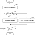
- FIG. 5 is a flowchart showing the operation of the processing device shown in FIG.
- FIG. 6 is a graph showing the output value of the sensor.
- FIG. 7 is a graph showing the results of processing the output values of the sensor by the process shown in FIG.
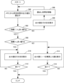
- FIG. 8 is a flowchart showing the operation of the processing device shown in FIG. 1, which is different from FIG.
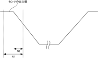
- FIG. 9 is a schematic diagram showing a method of calculating the index.
- FIG. 10 is a graph showing the calculated indexes.
- FIG. 11 is a graph showing the results of processing the sensor output values by the process shown in FIG.
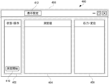
- FIG. 12 is a diagram showing a screen displayed on the display device.
- FIG. 13 shows a screen for setting display conditions for the measurement values.
- FIG. 14 is a diagram showing an example of displaying the measurement values.
- FIG. 15 is a diagram showing a display form different from that of FIG.
- FIG. 16 is a diagram showing a screen on which the state of the sensors arranged on the cutting tool is displayed superimposed on an image of the cutting tool.
- FIG. 17 is a diagram showing a screen in which the state of a sensor disposed on a cutting tool is displayed superimposed on an image of the cutting tool in a form different from that shown in FIG. FIG.
- FIG. 18 is a diagram showing a screen on which the stress acting on the cutting tool is displayed superimposed on an image of the cutting tool.
- FIG. 19 is a diagram showing a screen on which the displacement of the cutting tool is displayed superimposed on an image of the cutting tool.
- FIG. 20 is a diagram showing a screen on which the stress acting on the cutting tool is displayed in the form of vectors superimposed on an image of the cutting tool.
- FIG. 21 is a diagram showing a screen on which the displacement of the cutting tool is displayed in the form of vectors superimposed on an image of the cutting tool.
- the output value of the sensor (hereinafter also referred to as the measured value) is analyzed to monitor the cutting state (i.e., abnormal state, etc.). Since the positive or negative output value of the strain sensor is determined by the installation of the strain sensor on the cutting tool and the pressure applied during machining, the output value of the strain sensor during machining may become negative. In such cases, the worker may not be able to easily judge the cutting state (e.g., cannot intuitively judge). In addition, the strain value output from the strain sensor is difficult to physically interpret. In other words, it is difficult to grasp the physical changes of the cutting tool equipped with the strain sensor from the strain value.
- the present disclosure therefore aims to provide a processing device, processing method, system, and computer program that can easily determine the cutting state even when the sensor output value is negative, and can easily grasp physical changes in the cutting tool on which the sensor is mounted.
- a processing device includes a receiving unit that receives from the cutting tool an output value of a sensor mounted on the cutting tool, a processing unit that performs processing to invert the positive and negative of the output value based on the output value received by the receiving unit, and a display unit that displays the output value after the positive and negative of the output value have been inverted by the processing unit. This makes it easy to determine the cutting state even if the output value of the sensor is negative.
- the senor may include a strain sensor
- the processing unit may include a conversion unit that converts the output value of the strain sensor to calculate at least one of the stress applied to the cutting part of the cutting tool and the displacement of the cutting part. This makes it possible to easily grasp physical changes in the cutting tool on which the sensor is mounted during cutting processing.
- the display unit may display a tool image representing the cutting tool and a sensor image representing the sensor, and the sensor image may be displayed in a form according to the force acting on the sensor at a position on the tool image corresponding to the position where the sensor is disposed on the cutting tool. This allows the direction of stress (i.e., compression or tension) acting on the cutting tool on which the sensor is mounted during cutting processing to be understood, and the state of the cutting tool during cutting processing to be easily understood.
- stress i.e., compression or tension
- the conversion unit may calculate the stress
- the display unit may display a tool image representing the cutting tool and a vector image representing the stress
- the vector image may be displayed at a position on the tool image corresponding to the position on the cutting tool where the stress is to be calculated. This allows the stress acting on the cutting tool equipped with the sensor during cutting processing to be visually represented, and physical changes in the cutting tool to be easily understood.
- the conversion unit may calculate the displacement, and the display unit may display a tool image representing the cutting tool and a vector image representing the displacement, and the vector image may be displayed at a position on the tool image corresponding to the position on the cutting tool where the displacement is to be calculated.
- the conversion unit may calculate stress and displacement
- the display unit may switch between a first form in which a tool image representing the cutting tool and a first vector image representing stress are displayed, and a second form in which the tool image and a second vector image representing displacement are displayed, and the first vector image may be displayed at a position on the tool image corresponding to a position on the cutting tool where stress is to be calculated, and the second vector image may be displayed at a position on the tool image corresponding to a position on the tool image where displacement is to be calculated.
- the processing unit may include a determination unit that determines whether the output value is greater than a threshold value, and when the determination unit determines that the output value is greater than the threshold value, may perform processing to invert the positive and negative of the output value. In this way, when the output value of the sensor is negative, the positive and negative of the output value can be automatically inverted and displayed, making it easy to determine the cutting state.
- the processing unit may include a determination unit that determines, from a change in the output value, whether cutting by the cutting tool has started and the direction of change in the output value due to the start of cutting, and may perform processing to invert the positive and negative of the output value when the determination unit determines that the direction of change is a direction in which the output value is decreasing. In this way, when the output value of the sensor is negative, the positive and negative of the output value can be automatically inverted and displayed, making it easy to determine the cutting state.
- a processing method includes a receiving step in which a communication device receives from a cutting tool an output value of a sensor mounted on the cutting tool, a processing step in which a processing device performs processing to invert the positive and negative of the output value based on the output value received in the receiving step, and a display step in which a display device displays the output value after the positive and negative have been inverted in the processing step.
- a computer program causes a computer to realize a receiving function for receiving from the cutting tool an output value of a sensor mounted on the cutting tool, a processing function for performing processing to invert the positive and negative of the output value based on the output value received by the receiving function, and a display function for displaying the output value after the positive and negative of the output value have been inverted by the processing function. This makes it easy to determine the cutting state even if the output value of the sensor is negative.
- a system includes a sensor mounted on a cutting tool and a processing device according to any one of (1) to (8) above, and the cutting tool includes a communication unit that transmits an output value of the sensor to the processing device. This makes it easy to determine the cutting state even if the output value of the sensor is negative.
- a system 100 includes a processing device 102, a communication device 104, an operation device 106, a display device 108, and a sensor module 112.
- the processing device 102 is realized by, for example, a computer.
- the communication device 104 has a wireless function and receives data transmitted from a sensor module 112 mounted on a cutting tool 110.
- the communication device 104 functions as a receiving unit for the processing device 102.
- the cutting tool 110 is mounted on a cutting device 114 and used for cutting a workpiece.
- the cutting tool 110 is, for example, a turning tool.
- the cutting tool 110 may be a turning tool.
- the machining state by the cutting tool 110 is reflected in the measurement value (i.e., the output value of the sensor) by the sensor module 112.
- the communication device 104 outputs the received output value of the sensor to the processing device 102.
- the operation device 106 is a device for inputting instructions to the processing device 102.
- the operation device 106 includes, for example, a keyboard, a mouse, a touch panel, and the like for a computer.
- the display device 108 is an image display device such as a liquid crystal display device.
- the display device 108 functions as a display unit for the processing device 102.
- the processing device 102 stores and analyzes output values input from the communication device 104, and displays the output values and analysis results on the display device 108 in accordance with instructions from the operation device 106.
- FIG. 1 shows a case where the communication device 104, the operation device 106, and the display device 108 are arranged outside the processing device 102, some or all of them may be included in the processing device 102.
- a touch panel display may be used for the operation device 106 and the display device 108, and the touch panel display may be included in the processing device 102.
- the cutting tool 110 is a turning tool having a cutting insert 120.
- the cutting insert 120 has a cutting blade 122, which is a cutting part that is brought into contact with an object to be cut and cuts the object to be cut.
- the cutting blade 122 is detachably fixed by a fixing member 124.
- the cutting tool 110 has a sensor module 112A and a sensor module 112B disposed on a side surface 110A and a bottom surface 110B of the cutting tool 110, respectively.
- the sensor module 112A and the sensor module 112B are the same type of sensor and have the same configuration. Therefore, when there is no need to distinguish between the two, they are referred to as the sensor module 112.
- the sensor module 112A and the sensor module 112B may be disposed on a surface other than the side surface 110A and the bottom surface 110B of the cutting tool 110.
- FIG. 2 shows orthogonal right-handed XYZ axes set for the cutting tool 110. The X axis is perpendicular to the side surface 110A, and the Z axis is perpendicular to the bottom surface 110B.
- the sensor module 112 includes a sensor 130, an AD conversion unit 132, a memory 134, a control unit 136, a communication unit 138, a bus 140, and a power supply unit 142.
- the sensor 130 is a strain sensor.
- the sensor 130 may be a sensor other than a strain sensor, for example, an acceleration sensor.
- the AD conversion unit 132 converts an input analog signal into a digital signal and outputs it. That is, the AD conversion unit 132 samples the analog signal (i.e., the output value) output from the sensor 130 at a predetermined sampling frequency to generate a digital signal.
- the generated output value which is a digital signal, is transmitted to the memory 134 via the bus 140.
- the memory 134 is, for example, a rewritable nonvolatile semiconductor memory, and stores data transmitted via the bus 140.
- the memory 134 stores a computer program (hereinafter simply referred to as a program) executed by the control unit 136.
- the control unit 136 includes a CPU (Central Processing Unit).
- the control unit 136 reads the output values stored in the memory 134 and outputs them to the communication unit 138.
- the communication unit 138 transmits the input data to the outside of the sensor module 112, that is, to the communication device 104.
- the communication unit 138 has a wireless communication function such as Wi-Fi. Specifically, the communication unit 138 generates and transmits a communication packet including the data input from the control unit 136, the address of the communication device 104 as a destination address, and the address of the communication unit 138 as a source address. As a result, the communication packet transmitted from the communication unit 138 is received by the communication device 104.
- the bus 140 transmits data exchanged between the AD conversion unit 132, the memory 134, and the control unit 136.
- the power supply unit 142 supplies the power required for each unit constituting the sensor module 112 to function.
- the power supply unit 142 is, for example, a battery.
- the processing device 102 includes a control unit 160, an IF unit 162, a memory 164, and a bus 166.
- the control unit 160 is configured to include a CPU.
- the memory 164 is, for example, a rewritable non-volatile semiconductor memory, and stores the program executed by the control unit 160.
- the memory 164 may be a HDD (Hard Disk Drive).
- the memory 164 provides a work area for the program executed by the control unit 160.
- the IF unit 162 is an interface for exchanging data with each of the communication device 104, the operation device 106, and the display device 108.
- the IF unit 162 transmits data (i.e., the output value of the sensor) transmitted from the communication device 104 to the memory 164 via the bus 166 for storage.
- the IF unit 162 transmits instructions input by operating the operation device 106 to the control unit 160 via the bus 166.
- the control unit 160 executes the processing described below and stores the processing results in the memory 164.
- a part of the memory 164 functions as a video memory for storing video data corresponding to an image to be displayed on the display device 108.
- the IF unit 162 transmits the data in the video memory of the memory 164 to the display device 108 and displays it as an image on the display device 108.
- the memory 164 also stores information regarding the cutting tool 110.
- the information about the cutting tool 110 includes information about the type, shape, dimensions, and material of the cutting tool 110, as well as the placement positions of the sensor module 112A and the sensor module 112B.
- the operation of the processing device 102 will be described with reference to FIG. 5.
- the process shown in FIG. 5 is realized, for example, by the control unit 160 (see FIG. 4) reading and executing a predetermined program from the memory 164 in response to an instruction input to the processing device 102 by operating the operating device 106 during processing by the cutting device 114.
- the results of the process shown in FIG. 5 are appropriately stored in the memory 164.
- the output values of the sensors included in the sensor module 112A and the sensor module 112B mounted on the cutting tool 110 are sequentially transmitted to the communication device 104, received by the communication device 104, and stored in the memory 164 via the IF unit 162.
- the output values transmitted from the sensor module 112A and the sensor module 112B are distinguished by the source address included in the communication packet and stored in the memory 164 as respective time series data.
- the process shown in FIG. 5 is executed with the output values of each of sensor modules 112A and 112B as the processing target. For example, a program that processes the time series data of the output values measured by sensor module 112A and a program that processes the time series data of the output values measured by sensor module 112B are executed in parallel.
- the process shown in FIG. 5 may be executed while the output values are being received, or may be executed on the output values stored in memory 164 after cutting is completed.
- the output values are buffered for a predetermined period of time. In the following, it is described that the time series data of the output values of the sensor included in sensor module 112A is being processed.
- step 200 the control unit 160 reads out one output value from the time series data of the output values of the sensor included in the sensor module 112A that is stored in the memory 164. Then, control proceeds to step 202.
- step 202 the control unit 160 determines whether the output value read out in step 200 is greater than the threshold value Th1. If it is determined that the output value is greater, control proceeds to step 204. If not, control proceeds to step 206.
- the threshold value Th1 may be set in advance to an appropriate value according to the magnitude of the output value. For example, the threshold value Th1 may be set to - ⁇ so that a case in which the output value falls below the ⁇ of the noise when not processed can be detected. ⁇ is the standard deviation when the noise distribution is normal, and can be calculated by measuring the noise when not processed.
- step 204 the control unit 160 displays the output value read in step 200 as is on the display device 108. Thereafter, control proceeds to step 208.
- the control unit 160 stores the output value in the video memory of the memory 164 so that a graph is displayed with the output value on the vertical axis and the time axis on the horizontal axis.
- step 204 is executed repeatedly, so that the time series data of the sensor output value is displayed as a graph on the display device 108.
- step 208 the control unit 160 determines whether or not to end the program. If it is determined that the program should end, the program ends. If not, control returns to step 200, and the above process is repeated. For example, after the cutting device 114 has finished processing, if the operating device 106 is operated to input an end instruction to the processing device 102, the control unit 160 determines that the program should end. The control unit 160 may also automatically detect the end of processing and determine that the program should end.
- the time-series output value can be displayed as it is on the display device 108 as a graph of positive values.
- the output value of the sensor included in the sensor module 112A is a negative value equal to or less than the threshold value Th1 (i.e., the judgment result in step 202 is NO)
- the time-series output value can be inverted and displayed as a graph of positive values on the display device 108.
- the time-series data of the output value of the sensor included in the sensor module 112B can also be displayed in the same manner as the processing target.
- the control unit 160 functions as a processing unit that performs a process of inverting the positive and negative of the output value based on the output value in the processing device 102.
- the vertical axis represents the sensor output values as relative values.
- a scale below 0 is displayed on the vertical axis.
- the horizontal axis represents values corresponding to time.
- the horizontal dashed line represents the threshold value.
- the output value suddenly decreases from near 0 (i.e., the noise level) at time Ts. This indicates that cutting processing started at time Ts.
- the output value is a negative value. Thereafter, the output value suddenly increases and reaches near 0 (i.e., the noise level) at time Te. This indicates that cutting processing ended at time Te.
- the time series data shown in FIG. 6 is processed as shown in FIG. 5, it is displayed on the display device 108 as a graph as shown in FIG. 7.
- the vertical and horizontal axes in FIG. 7 have the same meaning as in FIG. 6. However, unlike FIG. 6, the vertical axis in FIG. 7 has a scale of 0 or more.
- output values greater than Th1 are displayed as is, and output values less than Th1 are displayed with their signs reversed, that is, as positive values.
- output values that were negative are displayed as positive values. Therefore, even if the sensor output value is negative, the cutting state can be easily determined. Note that in FIG. 7, before time Ts (i.e. before cutting) and after time Te (i.e. after cutting), noise below the threshold value is displayed with its signs reversed, as a positive value, and is not displayed below the threshold value (see the wavy lines in the left and right directions).
- the process of displaying the graph inverted when the output value from the sensor is negative so that the cutting state can be easily determined is not limited to the process shown in FIG. 5.
- the process according to the modified example detects the start of cutting processing, and inverts the sign of the output value depending on the positive or negative of the output value at the start of cutting processing.
- the process is shown in FIG. 8, for example.
- the process shown in FIG. 8 is realized by, for example, receiving an instruction input to the processing device 102 by operating the operation device 106 during processing by the cutting device 114, the control unit 160 (see FIG. 4) reading a predetermined program from the memory 164 and executing it. As in the case of FIG.
- the output values of the sensors included in each of the sensor modules 112A and 112B mounted on the cutting tool 110 are sequentially transmitted to the communication device 104 and stored in the memory 164.
- the process shown in FIG. 8 is executed with the output values of the sensors included in each of the sensor modules 112A and 112B as the processing target.
- the description will be given assuming that the time series data of the output values of the sensor included in the sensor module 112A is the processing target.
- control unit 160 reads the output values of a predetermined section from the time series data of the output values of the sensor included in sensor module 112A stored in memory 164. Thereafter, control proceeds to step 302. Specifically, referring to FIG. 9, control unit 160 reads the output values of N1 consecutive pieces of data from the time series output values.
- the control unit 160 calculates an index from the output value read out in step 300, and judges whether the absolute value is greater than a positive threshold value Th2, i.e., whether the index is less than -Th2 or greater than Th2. If it is greater (i.e.,
- the index is a value obtained by subtracting the moving average value A1 of the N1 output values from the moving average value A2 of the output values (number N2 (see FIG. 9)) of the data that is consecutive from the most recent output value among the N1 output values read out in step 300. That is,
- N1 and N2 are 200 and 100, respectively.
- the threshold value Th2 is set to ⁇ , for example, with ⁇ being the standard deviation of noise when not processed.
- step 304 the control unit 160 displays the output value read in step 300 as is on the display device 108. Thereafter, control proceeds to step 306. For example, the control unit 160 stores the output value in the video memory of the memory 164 so that a graph is displayed with the output value on the vertical axis and the time axis on the horizontal axis. As described below, step 304 is executed repeatedly, so that the time series data of the sensor output value is displayed as a graph on the display device 108.
- step 306 the control unit 160 shifts the section in which output values are read from the memory 164 in step 300 from the section read last time so that a newer output value is read. Thereafter, control returns to step 300. That is, a new section in which output values are read is set so that it does not include the oldest output value among the output values read last time, but includes the output value next to the newest output value. Note that when step 300 is executed for the second or subsequent time, the output value of the previous section has already been read, so the control unit 160 need only discard the oldest output value and read the output value to be newly read.
- the process of step 302 is a process for detecting the start of cutting. If the result of the determination in step 302 is YES, the start of cutting is detected, and step 308 described later is executed. If the result of the determination in step 302 is NO, the start of cutting has not been detected. Therefore, the output value readout section is moved and the determination in step 302 is repeated until the result of the determination in step 302 is YES (i.e., until the start of cutting is detected).
- FIG. 10 shows the time Ts (i.e., the start of cutting) shown in FIG. 6.
- the absolute value of the index is equal to or less than the threshold value Th2.
- the absolute value of the index is greater than the threshold value Th2. Therefore, if
- step 308 the control unit 160 determines whether the index is greater than the threshold value Th2. If it is determined that the index is greater, control proceeds to step 310. If not (i.e., the index is less than or equal to Th2), control proceeds to step 314.
- step 310 the control unit 160 reads the sensor output value from the memory 164 and displays the sensor output value directly on the display device 108, similar to step 304. Thereafter, control proceeds to step 312. By repeating step 310, the sensor output value is displayed as a time series graph on the display device 108.
- step 312 the control unit 160 determines whether or not to end the program. If it is determined that the program should end, the program ends. If not, control returns to step 310, and the processing of step 310 is repeated. For example, after the cutting device 114 has finished processing, if the operating device 106 is operated to input an end instruction to the processing device 102, the control unit 160 determines that the program should end. The control unit 160 may also automatically detect the end of processing and determine that the program should end.
- the judgment result in step 308 is NO (i.e., the index is equal to or less than the threshold value Th2)
- the judgment result in step 302 is YES (i.e., index ⁇ -Th2, or index>Th2),
- control unit 160 stores the positive value after the sign is inverted in the video memory of the memory 164, as in step 304.
- the sensor output value whose sign is inverted is displayed as a time series graph on the display device 108.
- step 316 the control unit 160 determines whether or not to end the program, similar to step 312. If it is determined that the program should end, the program ends. If not, control returns to step 314, and the processing of step 314 is repeated.
- the process of step 308 is a process for determining whether the sensor output value at the start of machining is positive or negative.
- the output value increases or decreases rapidly. If the sensor output value increases immediately after machining starts (i.e.,
- the index ⁇ threshold value Th2 If the index ⁇ threshold value Th2, then the index ⁇ -Th2, and the sensor output value is negative, and therefore the sign of the sensor output value is inverted in step 314 and displayed as a positive value. Therefore, even if the sensor output value is negative, the cutting state can be easily determined.
- the output value shown in FIG. 6, which displays the time series data of the sensor output value as it is, is the target of processing.
- the time series data shown in FIG. 6 is processed as shown in FIG. 8, it is displayed on the display device 108 as a graph as shown in FIG. 11.
- the meaning of the vertical and horizontal axes in FIG. 11 is the same as in FIG. 6.
- the vertical axis is displayed with a scale of 0 or more.
- the sign of the sensor output value is inverted, that is, it is displayed as a positive value.
- the output value that was negative is displayed as a positive value. Therefore, even if the sensor output value is negative, the cutting state can be easily determined.
- the output value is displayed with the sign inverted even after the end of cutting (after time Te). That is, if the sensor output value (i.e., noise) is a positive value, it is displayed as a negative value, and if the sensor output value (i.e., noise) is a negative value, it is displayed as a positive value.
- a display screen 400 displayed on the display device 108 includes an area 402, an area 404, an area 406, and an area 408.
- the area 402 displays information on the state and operation of the system.
- the state of the system is represented by information for identifying each sensor mounted on the cutting tool to be measured (e.g., the type and number of the sensor), the state of wireless communication, the remaining battery level of the sensor, and the like.
- Information on the operation is represented by the name of a file for saving the output data of the sensor, the protrusion amount, a measurement start button 410 for instructing the start of measurement, and the like.
- the processing device 102 instructs each sensor to transmit the output value of the sensor, and the transmission of the output value of the sensor is started. As a result, the output value of the sensor is received by the communication device 104 and transmitted to the processing device 102.
- the output values (i.e., measured values) of the sensor included in the sensor module 112 mounted on the cutting tool 110 are displayed as a time series graph as described above.
- physical quantities related to the cutting tool 110, specifically stress and displacement are displayed as information representing the state during cutting of the cutting tool 110 on which the sensor module 112 is mounted.
- a display setting button 412 for displaying a setting screen related to area 404 is displayed.
- a button for changing the display form of the display screen 400 i.e., icon display, window display, and full screen display
- a button for closing the display screen 400 are displayed.
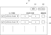
- the display setting screen 420 displayed by operating the display setting button 412 includes a plurality of areas 422, a save button 424, and a cancel button 426.
- each area 422 information related to the sensor type, the vertical axis display range, and the vertical axis inversion of the graph is set.
- the check box at the left end of each area 422 is for validating the settings in that area 422.
- the sensor type is information for identifying the sensor, and is selected from a plurality of displays such as sensor ch00 and sensor ch01 included in a pull-down menu displayed by operating a downward triangle.
- the range of the vertical axis of the graph displaying the output value is set by inputting a numerical value.
- the vertical axis inversion is a check box, and if the vertical axis inversion check box is not checked, the output value is displayed as it is, that is, the vertical axis scale is set to the upward direction of the value increase. On the other hand, if the vertical axis inversion check box is checked, the vertical axis is displayed inverted from the vertical axis when it is not checked, that is, the vertical axis scale is set to the upward direction of the value decrease.
- This graph display corresponds to a graph display in which the sign is inverted when the output value is negative, except that the sign of the vertical axis scale is reversed.
- the set information is stored in the memory 164 (see FIG. 4), the display setting screen 420 is erased from the display device 108, and the display screen 400 is displayed.
- the cancel button 426 is operated, the set information is discarded, the display setting screen 420 is erased from the display device 108, and the display screen 400 is displayed.
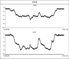
- a graph such as that shown in FIG. 15 is displayed in the area 404 shown in FIG. 12. That is, the output value of the ch01 sensor is displayed as is in the graph, but the output value of the ch00 sensor is displayed upside down, unlike in FIG. 14.
- the vertical axis of the graph for ch00 is displayed as a scale in which the upward direction is the direction in which the sensor output value decreases.
- the scale of the vertical axis of the graph for ch00 is the scale of ch01 inverted upside down. In this way, by making it possible to display an inverted graph when the output value of the strain sensor is negative, the cutting state can be easily determined even if the sensor output value is negative.
- Tool and physical quantity display An example of a screen displayed in the stress/displacement display area 406 is shown.
- the sensor images 130A and 103B representing the strain sensors included in the sensor modules 112A and 112B arranged on the side surface 110A and bottom surface 110B, respectively, are displayed by being superimposed on an image representing a turning tool (hereinafter, referred to as a tool image).
- the sensor images 130A and 103B are displayed at positions on the tool image corresponding to the positions at which the corresponding strain sensors are arranged on the turning tool.
- the reference symbols are not displayed on the display screen of the display device 108 (similarly in FIGS. 17 to 21).
- the tool image representing the turning tool can be generated by the control unit 160 of the processing device 102 from information on the cutting tool (e.g., CAD (Computer-Aided Design) data, CG (Computer Graphics) data, etc.) stored in the memory 164 (see FIG. 4). If the position of the strain sensor arranged on the cutting tool is also included in the information on the cutting tool, the position on the tool image corresponding to the position of the sensor can be calculated. Note that the tool image itself, which is a two-dimensional image, may be stored in the memory 164.
- CAD Computer-Aided Design
- CG Computer Graphics
- the sensor images 130A and 130B are displayed in different colors according to the force (i.e., tensile or compressive force) applied to each sensor, using a shape (e.g., a rectangle) representing each strain sensor. For example, tensile force is displayed in red, and compressive force is displayed in blue. Also, in FIG. 16, near the sensor images 130A and 130B, characters 430 (i.e., ch00) and 432 (i.e., ch01) are displayed as information for distinguishing each sensor on the turning tool.
- characters 430 i.e., ch00
- 432 i.e., ch01
- the tool image and the superimposed sensor images 130A and 130B may be rotated and displayed according to the operation of the operating device 106 (e.g., a computer mouse or touch panel). Furthermore, when a tool image is generated from CAD data or CG data, it can be displayed as a two-dimensional image seen from a viewpoint according to an operation on the display device 108. This operation makes it easier to grasp the state of the cutting tool during cutting processing.
- FIG. 17 it may be displayed as shown in FIG. 17.
- sensor images 130A and 103B representing the strain sensors included in sensor module 112A and sensor module 112B arranged on side surface 110A and bottom surface 110B, respectively, are displayed superimposed on a tool image representing the turning tool.
- characters 430 and characters 432 are displayed as information for distinguishing each sensor on the turning tool.
- arrows 500 and 502 representing the force (i.e., tensile force or compressive force) applied to the strain sensor are displayed near sensor image 130A and sensor image 130B, respectively.
- the stress direction (i.e., compressive or tensile) applied to the cutting tool (i.e., turning tool) on which the sensor (i.e., strain sensor) is mounted can be grasped during cutting (i.e., turning), and the state of the cutting tool during cutting can be easily grasped.
- the sensor images 130A and 103B may be displayed in the same color or in different colors depending on the force applied to the sensor (i.e., tensile or compressive force).
- the arrows 500 and 502 may be displayed in the same color or in different colors depending on the force applied to the sensor.
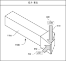
- vector images 510 and 512 representing the stress acting on the cutting edge calculated from the output values of the two strain sensors are displayed at positions on the tool image corresponding to the cutting edge, superimposed on the tool image representing the turning tool.
- the vector images 510 and 512 represent the stress calculated from the output values of the sensors arranged on the bottom surface 110B and the side surface 110A of the cutting tool, respectively. Therefore, the direction of the vector image 510 is perpendicular to the bottom surface 110B (i.e., the negative direction of the Z axis shown in FIG.
- Characters 430 and 432 are displayed near the vector images 510 and 512 as information representing the corresponding sensors.
- the vector images 510 and 512 have lengths according to the magnitude of the stress (i.e., the stress value).
- the end points of vector image 510 and vector image 512 are displayed so as to be located at the position where the displayed stress is calculated (hereinafter referred to as the calculation target position), i.e., the cutting edge.
- vector image 510 and vector image 512 may be displayed in the same color or in different colors.
- vector images 514 and 516 representing the displacement at the cutting edge calculated from the output values of the two strain sensors are displayed at the position of the cutting edge, superimposed on a tool image representing the turning tool.
- Vector images 514 and 516 represent the displacement calculated from the output values of sensors arranged on the bottom surface 110B and side surface 110A of the cutting tool, respectively. Therefore, the direction of vector image 514 is perpendicular to bottom surface 110B (i.e., the negative direction of the Z axis shown in FIG. 2), and the direction of vector image 516 is perpendicular to side surface 110A (i.e., the negative direction of the X axis shown in FIG. 2).
- Characters 430 and 432 are displayed near vector images 514 and 516 as information representing the corresponding sensors.
- Vector images 514 and 516 have lengths according to the magnitude of the displacement (i.e., the amount of displacement).
- the starting points (corresponding to the starting points of the vectors) of vector image 514 and vector image 516 are displayed so as to be located at the position where the displacement to be displayed is calculated (i.e., the calculation target position), i.e., the cutting edge.
- This makes it possible to visually represent the displacement that occurs in a cutting tool (i.e., a turning tool) equipped with a sensor (i.e., a strain sensor) during cutting (i.e., turning), and makes it easy to grasp the physical changes in the cutting tool.
- vector image 514 and vector image 516 may be displayed in the same color or in different colors.
- the display may be switched between a first form in which a vector image representing stress is superimposed on the cutting tool as shown in FIG. 18, and a second form in which a vector image representing displacement is superimposed on the cutting tool as shown in FIG. 19.
- a cutting tool i.e., turning tool
- a sensor i.e., strain sensor
- the stress applied to the cutting edge of a cutting tool (including a turning tool) and the displacement of the cutting edge can be calculated from the strain value, which is the output value of the strain sensor, taking into consideration the shape, dimensions, material, and protrusion amount of the cutting tool, as well as the mounting position of the strain sensor on the cutting tool.
- the protrusion amount represents the distance from the mounting position of the cutting tool on the cutting device (i.e., the reference position for calculating stress and displacement) to the cutting edge.
- the stress applied to the cutting edge of a cutting tool (including a turning tool) and the displacement of the cutting edge are calculated by the control unit 160 of the processing device 102. That is, the control unit 160 functions as a conversion unit in the processing device 102 that converts the output value of the sensor into stress and displacement.
- a turning tool is provided with a strain sensor that detects strain in three orthogonal directions
- the stress acting on the turning tool may be displayed, for example, as shown in FIG. 20.
- a vector image 520 which is a three-dimensional vector representing the stress acting on the cutting edge calculated from the output value of the strain sensor, is displayed at the position of the cutting edge by being superimposed on an image representing the turning tool.
- the end point of the vector image 520 (corresponding to the end point of the vector) is displayed so as to be located at the position where the displayed stress is calculated (i.e., the calculation target position), i.e., the cutting edge.
- the displacement of the turning tool may be displayed, for example, as shown in FIG. 21.
- a vector image 522 which is a three-dimensional vector representing the displacement at the cutting edge calculated from the output value of the strain sensor, is displayed at the position of the cutting edge, superimposed on an image representing the turning tool.
- the start point of the vector image 522 (corresponding to the start point of the vector) is displayed so as to be located at the position where the displayed displacement is calculated (i.e., the calculation target position), that is, the cutting edge.
- a cutting tool i.e., turning tool
- a sensor i.e., strain sensor
- the display may be switched between a first form in which a vector image representing stress is superimposed on the cutting tool as shown in FIG. 20, and a second form in which a vector image representing displacement is superimposed on the cutting tool as shown in FIG. 21.
- a cutting tool i.e., turning tool
- a sensor i.e., strain sensor
- the number of tool images displayed in area 406 shown in FIG. 13 is not limited to one. Multiple tool images may be displayed. For example, if a graph relating to multiple sensors is displayed in area 404, a tool image corresponding to each of the multiple sensors may be displayed.
- each process (each function) of the above-mentioned embodiments may be realized by a processing circuit (circuitry) including one or more processors.
- the processing circuit may be configured by an integrated circuit or the like that combines one or more memories, various analog circuits, and various digital circuits in addition to the one or more processors.
- the one or more memories store programs (instructions) that cause the one or more processors to execute each of the above processes.
- the one or more processors may execute each of the above processes according to the programs read from the one or more memories, or may execute each of the above processes according to a logic circuit that has been designed in advance to execute each of the above processes.
- the processor may be a CPU, a GPU (Graphics Processing Unit), a DSP (Digital Signal Processor), an FPGA (Field Programmable Gate Array), an ASIC (Application Specific Integrated Circuit), or any other processor suitable for computer control.
- a recording medium can be provided that records a program for causing a computer to execute the processing of the processing device 102 (specifically, the process of inverting the positive and negative of the output value (for example, the process shown in Figures 6 and 8)).
- the recording medium is, for example, an optical disk (such as a DVD (Digital Versatile Disc)) or a removable semiconductor memory (such as a USB (Universal Serial Bus) memory).
- a computer program can be transmitted over a communication line, the recording medium refers to a non-temporary recording medium.
- the computer can transmit data that can be effectively used by the service provided by the external device, taking into account the delay time and communication bandwidth when the vehicle-mounted device uploads data to an external device such as a roadside device, as described above.
- the computer-readable non-transitory recording medium is On the computer, a receiving function for receiving an output value of a sensor mounted on the cutting tool from the cutting tool; a processing function for performing a process of inverting the positive and negative of the output value based on the output value received by the receiving function; and a display function for displaying the output value after the sign has been inverted by the processing function.
Landscapes
- Engineering & Computer Science (AREA)
- Mechanical Engineering (AREA)
- Machine Tool Sensing Apparatuses (AREA)
- Cutting Tools, Boring Holders, And Turrets (AREA)
- Numerical Control (AREA)
Priority Applications (2)
| Application Number | Priority Date | Filing Date | Title |
|---|---|---|---|
| JP2023521716A JP7384320B1 (ja) | 2022-11-01 | 2022-11-01 | 処理装置、処理方法、システムおよびコンピュータプログラム |
| PCT/JP2022/040862 WO2024095361A1 (ja) | 2022-11-01 | 2022-11-01 | 処理装置、処理方法、システムおよびコンピュータプログラム |
Applications Claiming Priority (1)
| Application Number | Priority Date | Filing Date | Title |
|---|---|---|---|
| PCT/JP2022/040862 WO2024095361A1 (ja) | 2022-11-01 | 2022-11-01 | 処理装置、処理方法、システムおよびコンピュータプログラム |
Publications (1)
| Publication Number | Publication Date |
|---|---|
| WO2024095361A1 true WO2024095361A1 (ja) | 2024-05-10 |
Family
ID=88833353
Family Applications (1)
| Application Number | Title | Priority Date | Filing Date |
|---|---|---|---|
| PCT/JP2022/040862 Ceased WO2024095361A1 (ja) | 2022-11-01 | 2022-11-01 | 処理装置、処理方法、システムおよびコンピュータプログラム |
Country Status (2)
| Country | Link |
|---|---|
| JP (1) | JP7384320B1 (https=) |
| WO (1) | WO2024095361A1 (https=) |
Families Citing this family (1)
| Publication number | Priority date | Publication date | Assignee | Title |
|---|---|---|---|---|
| JP7796301B1 (ja) * | 2024-10-30 | 2026-01-08 | 住友電工ハードメタル株式会社 | 管理装置、管理装置の制御方法およびそれに用いられるプログラム、ならびに切削システム |
Citations (4)
| Publication number | Priority date | Publication date | Assignee | Title |
|---|---|---|---|---|
| JP2003223205A (ja) * | 2003-01-20 | 2003-08-08 | Mitsubishi Electric Corp | 工作機械制御装置 |
| JP2020163564A (ja) * | 2019-03-28 | 2020-10-08 | 日立金属株式会社 | 加工装置及びそれを用いた被削性評価方法 |
| WO2021241150A1 (ja) * | 2020-05-26 | 2021-12-02 | 住友電気工業株式会社 | 管理装置、表示処理方法および表示処理プログラム |
| JP2022111857A (ja) * | 2021-01-20 | 2022-08-01 | 日立建機株式会社 | 衛星測位システム及びサーバ装置 |
-
2022
- 2022-11-01 WO PCT/JP2022/040862 patent/WO2024095361A1/ja not_active Ceased
- 2022-11-01 JP JP2023521716A patent/JP7384320B1/ja active Active
Patent Citations (4)
| Publication number | Priority date | Publication date | Assignee | Title |
|---|---|---|---|---|
| JP2003223205A (ja) * | 2003-01-20 | 2003-08-08 | Mitsubishi Electric Corp | 工作機械制御装置 |
| JP2020163564A (ja) * | 2019-03-28 | 2020-10-08 | 日立金属株式会社 | 加工装置及びそれを用いた被削性評価方法 |
| WO2021241150A1 (ja) * | 2020-05-26 | 2021-12-02 | 住友電気工業株式会社 | 管理装置、表示処理方法および表示処理プログラム |
| JP2022111857A (ja) * | 2021-01-20 | 2022-08-01 | 日立建機株式会社 | 衛星測位システム及びサーバ装置 |
Also Published As
| Publication number | Publication date |
|---|---|
| JPWO2024095361A1 (https=) | 2024-05-10 |
| JP7384320B1 (ja) | 2023-11-21 |
Similar Documents
| Publication | Publication Date | Title |
|---|---|---|
| JP7384321B1 (ja) | 処理装置、処理方法、システムおよびコンピュータプログラム | |
| US11125634B2 (en) | Residual stress estimation method and residual stress estimation device | |
| TWI773883B (zh) | 工廠評價裝置、工廠評價方法及工廠評價程式 | |
| WO2002011953A1 (fr) | Cle dynamometrique pour inspection de serrage supplementaire | |
| WO2024095361A1 (ja) | 処理装置、処理方法、システムおよびコンピュータプログラム | |
| US12275150B2 (en) | Method of setting control parameter of robot, robot system, and computer program | |
| JP7087882B2 (ja) | 品質予測装置、品質予測方法、及び品質予測プログラム | |
| JP6864297B2 (ja) | 加工状態情報推定装置及び加工状態診断装置 | |
| JP5314560B2 (ja) | 加工シミュレーション装置、加工シミュレーション方法、プログラム、記録媒体 | |
| JP2008298429A (ja) | 材料状態推定方法 | |
| JP2018156340A (ja) | 診断装置、診断システム、診断方法およびプログラム | |
| WO2021157446A1 (ja) | 形状検出方法、形状検出システム、プログラム | |
| WO2019049199A1 (ja) | データ表示システム、表示装置およびデータ表示方法 | |
| US11514384B2 (en) | Productivity improvement support system and productivity improvement support method | |
| JPWO2024095361A5 (https=) | ||
| JP6996642B2 (ja) | 情報処理装置、制御方法、及びプログラム | |
| EP3875940A1 (en) | Material testing machine | |
| JP7287671B2 (ja) | 工具システム及び工具システム用プログラム | |
| JP6758695B1 (ja) | 形状検出方法、形状検出システム、プログラム | |
| JP6742661B1 (ja) | 形状検出方法、形状検出システム、プログラム | |
| WO2020065959A1 (ja) | 情報処理装置、制御方法、及びプログラム | |
| JP2011209912A (ja) | 応力歪解析装置及び応力歪の解析方法 | |
| JP7311319B2 (ja) | 時系列データ表示装置 | |
| JP2007004552A (ja) | 積層材料の解析方法 | |
| WO2025191703A1 (ja) | 表示画像生成システム |
Legal Events
| Date | Code | Title | Description |
|---|---|---|---|
| ENP | Entry into the national phase |
Ref document number: 2023521716 Country of ref document: JP Kind code of ref document: A |
|
| 121 | Ep: the epo has been informed by wipo that ep was designated in this application |
Ref document number: 22964383 Country of ref document: EP Kind code of ref document: A1 |
|
| NENP | Non-entry into the national phase |
Ref country code: DE |
|
| 122 | Ep: pct application non-entry in european phase |
Ref document number: 22964383 Country of ref document: EP Kind code of ref document: A1 |