WO2024090442A1 - 静圧気体軸受装置 - Google Patents
静圧気体軸受装置 Download PDFInfo
- Publication number
- WO2024090442A1 WO2024090442A1 PCT/JP2023/038377 JP2023038377W WO2024090442A1 WO 2024090442 A1 WO2024090442 A1 WO 2024090442A1 JP 2023038377 W JP2023038377 W JP 2023038377W WO 2024090442 A1 WO2024090442 A1 WO 2024090442A1
- Authority
- WO
- WIPO (PCT)
- Prior art keywords
- groove
- porous body
- bearing device
- hydrostatic gas
- gas bearing
- Prior art date
- Legal status (The legal status is an assumption and is not a legal conclusion. Google has not performed a legal analysis and makes no representation as to the accuracy of the status listed.)
- Ceased
Links
Images






Classifications
-
- F—MECHANICAL ENGINEERING; LIGHTING; HEATING; WEAPONS; BLASTING
- F16—ENGINEERING ELEMENTS AND UNITS; GENERAL MEASURES FOR PRODUCING AND MAINTAINING EFFECTIVE FUNCTIONING OF MACHINES OR INSTALLATIONS; THERMAL INSULATION IN GENERAL
- F16C—SHAFTS; FLEXIBLE SHAFTS; ELEMENTS OR CRANKSHAFT MECHANISMS; ROTARY BODIES OTHER THAN GEARING ELEMENTS; BEARINGS
- F16C32/00—Bearings not otherwise provided for
- F16C32/06—Bearings not otherwise provided for with moving member supported by a fluid cushion formed, at least to a large extent, otherwise than by movement of the shaft, e.g. hydrostatic air-cushion bearings
- F16C32/0603—Bearings not otherwise provided for with moving member supported by a fluid cushion formed, at least to a large extent, otherwise than by movement of the shaft, e.g. hydrostatic air-cushion bearings supported by a gas cushion, e.g. an air cushion
- F16C32/0614—Bearings not otherwise provided for with moving member supported by a fluid cushion formed, at least to a large extent, otherwise than by movement of the shaft, e.g. hydrostatic air-cushion bearings supported by a gas cushion, e.g. an air cushion the gas being supplied under pressure, e.g. aerostatic bearings
-
- F—MECHANICAL ENGINEERING; LIGHTING; HEATING; WEAPONS; BLASTING
- F16—ENGINEERING ELEMENTS AND UNITS; GENERAL MEASURES FOR PRODUCING AND MAINTAINING EFFECTIVE FUNCTIONING OF MACHINES OR INSTALLATIONS; THERMAL INSULATION IN GENERAL
- F16C—SHAFTS; FLEXIBLE SHAFTS; ELEMENTS OR CRANKSHAFT MECHANISMS; ROTARY BODIES OTHER THAN GEARING ELEMENTS; BEARINGS
- F16C32/00—Bearings not otherwise provided for
- F16C32/06—Bearings not otherwise provided for with moving member supported by a fluid cushion formed, at least to a large extent, otherwise than by movement of the shaft, e.g. hydrostatic air-cushion bearings
-
- G—PHYSICS
- G03—PHOTOGRAPHY; CINEMATOGRAPHY; ANALOGOUS TECHNIQUES USING WAVES OTHER THAN OPTICAL WAVES; ELECTROGRAPHY; HOLOGRAPHY
- G03F—PHOTOMECHANICAL PRODUCTION OF TEXTURED OR PATTERNED SURFACES, e.g. FOR PRINTING, FOR PROCESSING OF SEMICONDUCTOR DEVICES; MATERIALS THEREFOR; ORIGINALS THEREFOR; APPARATUS SPECIALLY ADAPTED THEREFOR
- G03F7/00—Photomechanical, e.g. photolithographic, production of textured or patterned surfaces, e.g. printing surfaces; Materials therefor, e.g. comprising photoresists; Apparatus specially adapted therefor
- G03F7/20—Exposure; Apparatus therefor
-
- H—ELECTRICITY
- H10—SEMICONDUCTOR DEVICES; ELECTRIC SOLID-STATE DEVICES NOT OTHERWISE PROVIDED FOR
- H10P—GENERIC PROCESSES OR APPARATUS FOR THE MANUFACTURE OR TREATMENT OF DEVICES COVERED BY CLASS H10
- H10P72/00—Handling or holding of wafers, substrates or devices during manufacture or treatment thereof
- H10P72/70—Handling or holding of wafers, substrates or devices during manufacture or treatment thereof for supporting or gripping
-
- H—ELECTRICITY
- H10—SEMICONDUCTOR DEVICES; ELECTRIC SOLID-STATE DEVICES NOT OTHERWISE PROVIDED FOR
- H10P—GENERIC PROCESSES OR APPARATUS FOR THE MANUFACTURE OR TREATMENT OF DEVICES COVERED BY CLASS H10
- H10P76/00—Manufacture or treatment of masks on semiconductor bodies, e.g. by lithography or photolithography
Definitions
- This disclosure relates to a hydrostatic gas bearing device.
- air slides are used as devices for scanning and positioning stages with high precision.
- Examples of such air slides include those that use orifice diaphragms and surface diaphragms. With such air slides, if foreign matter gets into the gas supply hole, the amount of gas supplied changes, reducing rigidity and making the dynamic posture of the moving body unstable.
- a hydrostatic bearing device is used in which a porous member is provided in the bearing section, and the porous member is provided with an air supply hole and an exhaust groove for exhausting the pressurized fluid.
- the hydrostatic bearing device described in Patent Document 1 can increase the area in which compressed gas is ejected. As a result, the bearing rigidity can be increased, but there is an issue that vibrations are generated due to the compression effect of the gas within the porous body.
- the hydrostatic gas bearing device comprises a movable member and a fixed member.
- a recess is located on the bearing surface of the base of the movable member or the fixed member, and the opening of the gas supply hole is located on the bottom surface of the recess.
- a porous body that serves as the gas outlet is located in the recess so as not to protrude from the bearing surface.
- a first groove is located on the surface of the porous body, extending from the central region of the surface to the outer periphery of the porous body.
- a second groove that communicates with the first groove is located on the bearing surface of the base.
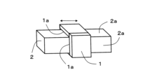
- FIG. 1 is an explanatory diagram showing an example in which a hydrostatic gas bearing device according to an embodiment of the present disclosure is provided in a linear guide device.
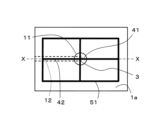
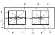
- 1 is a plan view showing a main portion of an externally pressurized gas bearing device according to an embodiment of the present disclosure.
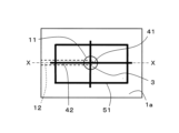
- FIG. 11 is a plan view showing a modified example of a main part of an externally pressurized gas bearing device according to an embodiment of the present disclosure.
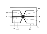
- FIG. 11 is a plan view showing another modified example of the main part of the hydrostatic gas bearing device according to an embodiment of the present disclosure.
- FIG. 2B is an explanatory diagram showing a cross section taken along line XX in FIG. 2A.
- FIG. 4 is a plan view showing the bottom surface of the recessed portion.
- FIG. 11 is a plan view showing a main portion of a hydrostatic gas bearing device according to another embodiment of the present disclosure.
- FIG. 13 is a plan view showing a main portion of a hydrostatic gas bearing device according to still another embodiment of the present disclosure.
- FIG. 13 is a plan view showing a main portion of a hydrostatic gas bearing device according to still another embodiment of the present disclosure.
- FIG. 11 is a plan view showing a main portion of a hydrostatic gas bearing device according to still another embodiment of the present disclosure.
- FIG. 13 is a plan view showing a main portion of a hydrostatic gas bearing device according to still another embodiment of the present disclosure.
- FIG. 13 is a plan view showing a main portion of a hydrostatic gas bearing device according to still another embodiment of the present disclosure.
- FIG. 13 is a plan view showing a main portion of a hydrostatic gas bearing device according to still another embodiment of the present disclosure.
- FIG. 13 is a plan view showing a main portion of a hydrostatic gas bearing device according to still
- FIG. 13 is a plan view showing a main portion of a hydrostatic gas bearing device according to still another embodiment of the present disclosure.
- FIG. 13 is a plan view showing a main portion of a hydrostatic gas bearing device according to still another embodiment of the present disclosure.
- FIG. 13 is a plan view showing a main portion of a hydrostatic gas bearing device according to still another embodiment of the present disclosure.
- the hydrostatic gas bearing device disclosed herein has the above-mentioned configuration, which makes it possible to reduce the decrease in rigidity caused by micro-vibrations and clogging of the gas supply holes.
- FIG. 1 is an explanatory diagram showing an example in which a hydrostatic gas bearing device according to one embodiment of the present disclosure is provided on a linear guide device.
- the hydrostatic gas bearing device according to one embodiment includes a movable member 1 and a fixed member 2.
- the movable member 1 is arranged to surround the fixed member 2, which has a roughly rectangular prism shape.
- the movable member 1 and the fixed member 2 are positioned with a gap between them, and are not in contact.
- a hydrostatic gas layer is formed by ejecting compressed gas from the bearing surface 1a of the base of the movable member 1 or the bearing surface 2a of the base of the fixed member 2. Therefore, with the movable member 1 and the fixed member 2 in a non-contact state, the movable member 1 can be moved along the fixed member 2 using a separate driving means (not shown).
- the movable member 1 and the fixed member 2 are formed, for example, from ceramics or metals.
- ceramics forming the movable member 1 and the fixed member 2 include ceramics whose main components are alumina, zirconia, silicon carbide, silicon nitride, or aluminum nitride.
- metals include aluminum and stainless steel.
- the movable member 1 and the fixed member 2 may be formed from the same material or different materials.
- main component means a component that accounts for 80% or more by mass out of a total of 100% by mass of the components that make up the ceramic.
- Each component contained in the ceramic is identified using an X-ray diffraction device that uses CuK ⁇ radiation, and the content of each component can be determined, for example, using an ICP (Inductively Coupled Plasma) emission spectrometer or an X-ray fluorescence analyzer.
- ICP Inductively Coupled Plasma
- Figure 2A is a plan view showing the main parts of a hydrostatic gas bearing device according to one embodiment of the present disclosure.
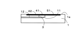
- Figure 3 is an explanatory diagram showing a cross section taken along line X-X in Figure 2A.
- Figure 4 is a plan view showing the bottom surface 11a of the recess 11. As shown in Figures 2A to 4, the bearing surface 1a of the base of the movable member 1 is provided with the recess 11 and a gas supply hole 12 having an opening 12a in part of the bottom surface 11a of the recess 11.
- the porous body 3 is located in the recess 11.
- the depth of the recess 11 is not limited, and is, for example, 1 mm or more and 10 mm or less.
- the porous body 3 is a member that serves as the gas ejection portion.
- the porous body 3 is fixed to the recess 11 so as not to protrude from the bearing surface 1a of the base of the movable member 1.
- a gas supply hole 12 that communicates with the outside of the movable member 1 is connected to the bottom surface 11a of the recess 11.
- the gas supply hole 12 has an opening 12a in part of the bottom surface 11a of the recess 11. Gas is supplied from the outside of the movable member 1 through the gas supply hole 12 to the porous body 3 that serves as the ejection part.
- the gas supply hole 12 may be, for example, a horizontal hole formed from the side surface of the base, a vertical hole formed from the bottom surface of the base, or a combination of a horizontal hole formed from the side surface of the base and a vertical hole connecting the horizontal hole and the bottom surface 11a.
- the porous body 3 is made of, for example, ceramics. Examples of such ceramics include ceramics mainly composed of alumina, zirconia, silicon carbide, silicon nitride, or aluminum nitride.
- the porous body 3 may be made of the same material as the member in which the recess 11 is located (in one embodiment, the movable member 1). When the porous body 3 is made of the same material as the member in which the recess 11 is located, differences in thermal expansion coefficients are unlikely to occur and stress is unlikely to occur even when the temperature changes. Therefore, turbulence is unlikely to occur due to deformation, etc., and micro-vibrations due to turbulence are further reduced.
- the porosity of the porous body 3 is not limited and may be, for example, 20% to 50%.
- the average particle size of the porous body 3 is not limited and may be, for example, 10 ⁇ m to 100 ⁇ m.
- the porosity of the porous body 3 can be determined, for example, by mercury intrusion porosimetry.
- Mercury intrusion porosimetry is a method in which mercury is injected (mercury intrusion porosimetry) into the pores of the porous body 3 (sample) using a mercury intrusion porosimeter to determine the porosity, and can be determined in accordance with JIS R 1655-2003.
- the thickness of the porous body 3 is not limited as long as it does not protrude from the recess 11.
- the upper surface of the porous body 3 and the bearing surface of the base in one embodiment, the bearing surface 1a of the base of the movable member 1 may be flush.
- turbulence due to the step between the upper surface of the porous body 3 and the bearing surface of the base is less likely to occur. As a result, micro-vibrations caused by turbulence are further reduced.
- At least the bottom surface of the porous body 3 may be bonded to the bottom surface 11a of the recess 11.
- the fixing strength of the porous body 3 can be increased.
- the bonding method is not limited, and for example, the porous body 3 may be bonded using an epoxy adhesive such as Araldite (registered trademark, manufactured by Huntsman Japan) and Thor Seal (manufactured by Agilent).
- the porous body 3 may be bonded to the entire surface of the recess 11 other than the opening 12a of the gas supply hole 12.
- the gas flows more easily from the gas supply hole 12 to the first groove 41 described later. As a result, the gas is more easily dispersed throughout the porous body 3, and micro-vibrations are further reduced.
- the surface of the porous body 3 is provided with a plurality of radial first grooves 41.
- the first grooves 41 are formed from the central region of the porous body 3 toward the outside, as shown in FIG. 2A.
- the number of first grooves 41 may be three or more and eight or less.
- the width and depth of the first grooves 41 are not limited. The width may be, for example, 0.5 mm or more and 2 mm or less. The depth may be, for example, 0.005 mm or more and 0.05 mm or less.
- the cross-sectional shape perpendicular to the length direction of the first groove 41 is not particularly limited.
- This cross-sectional shape may be, for example, a U-shape in which the opening and bottom of the groove are the same width, or a V-shape in which the opening width of the groove is larger than the bottom width, or a U-shape (shape with a curved bottom).
- the groove may be a V-shape or a U-shape in which the opening width of the groove is larger than the bottom width.
- the width is smaller than the depth. Therefore, since losses due to resistance are likely to be large, it is better for the width of the groove to be larger than the depth. However, if the depth is too large compared to the width, micro-vibrations are likely to increase. Therefore, the width should be 100 times or less than the depth.
- the angles formed by two adjacent first grooves 41 in a plurality of first grooves 41 may have the same angle. With such a configuration, the gas flowing through the first grooves 41 becomes more uniform. As a result, the variation in the gas flow is reduced.
- four first grooves 41 are formed at intervals of 90°.
- the bearing surface of the base (in one embodiment, the bearing surface 1a of the base of the movable member 1) is provided with a plurality of second grooves 42 that communicate with the first grooves 41.
- the second groove 42 is connected to the first groove 41, and is therefore positioned in a straight line with the first groove 41, as shown in FIG. 2A.
- the width and depth of the second groove 42 are, for example, the same as the width and depth of the first groove 41.
- the hydrostatic gas bearing device has a first groove 41 and a second groove 42. Therefore, the gas ejected from the porous body 3 can be moved to the second groove 42 by the first groove 41. As a result, the gas can be moved to the base of the movable member 1. Therefore, a buoyancy force can be generated in the base of the movable member 1, and the buoyancy force is stabilized, reducing micro-vibrations.
- the bearing surface 1a of the base may be provided with a first intersecting groove 51 that intersects with the second groove 42.
- the gas flowing through the second groove 42 can be dispersed in a direction that intersects with the second groove 42, further reducing micro-vibrations.
- Examples of "intersecting” include two-crossing, three-crossing, and four-crossing.
- Two-crossing means a structure that faces in two directions from an intersection, such as an L-shape.
- Three-crossing means a structure that faces in three directions from an intersection, such as a T-shape and a Y-shape.
- Four-crossing means a structure that faces in four directions from an intersection, such as a cross shape, an X-shape, and a swastika shape.
- the first intersecting groove 51 may be connected at the end of the second groove 42, or may be connected midway through the second groove 42.
- the first intersecting groove 51 may be connected at its end to the second groove 42, or may be connected midway through the first intersecting groove 51 to the second groove 45.
- the first intersecting groove 51 may connect adjacent second grooves 45. This makes it easier to supply gas uniformly to the bearing surface 1a.
- the first intersecting groove 51 is positioned so as to connect the ends of the second grooves 42.
- the first intersecting groove 51 is formed in a rectangular shape to match the rectangular bearing surface 1a when viewed in a plan view. In this way, it is preferable to form the first intersecting groove 51 parallel to the outer shape of the bearing surface 1a.
- the shape of the first intersecting groove 51 is not limited as long as it is formed so as to connect the second grooves 42.
- the first intersecting groove 51 may be formed in a ring shape so as to connect the second grooves 42 together, as shown in FIG. 2A.
- the first intersecting groove 51 may be similar in shape to the bearing surface 1a of the base (if the bearing surface 1a is rectangular as shown in FIG. 2A, the first intersecting groove 51 may be rectangular). This makes it easier for gas to be supplied uniformly to the bearing surface 1a.
- the width and depth of the first intersecting groove 51 are, for example, the same as the width and depth of the first groove 41.
- FIG. 2A is formed in an annular shape so as to connect the ends of the second grooves 42.
- the first intersecting groove 51 may be formed in an annular shape so as to connect portions other than the ends of the second grooves 42.
- FIG. 2B is a plan view showing a modified example of a main part of a hydrostatic gas bearing device according to an embodiment of the present disclosure.
- FIG. 2C is a plan view showing another modified example of the main part of the hydrostatic gas bearing device according to one embodiment of the present disclosure.
- the porous body 3 may further be provided with at least one second intersecting groove 52 that intersects and connects with the first groove 41.
- FIG. 5 is a plan view showing a main portion of a hydrostatic gas bearing device according to another embodiment of the present disclosure. By providing the second intersecting groove 52, the variation in the gas flow is reduced. The second intersecting groove 52 may connect between a plurality of first grooves 41. This makes it easier for gas to be supplied uniformly to the surface of the porous body 3.
- the second intersecting groove 52 may have a similar shape to the porous body 3 when viewed in a plan view.
- the porous body 3 has a circular shape when viewed in a plan view
- the second intersecting groove 52 also has a circular shape (annular shape).
- the second intersecting groove 52 has a circular shape (annular shape).
- the second intersecting groove 52 is not limited to annular shape as long as it has a shape that can connect the first grooves 41.
- the arithmetic mean roughness Ra of the bearing surface of the base (bearing surface 1a of the base of the movable member 1), the surface of the porous body 3, and the inner wall surface of each groove is not limited.
- the arithmetic mean roughness Ra of the bearing surface of the base may be smaller than the arithmetic mean roughness Ra of the inner wall surface of the second groove 42. If the arithmetic mean roughness Ra of the bearing surface of the base is smaller than the arithmetic mean roughness Ra of the inner wall surface of the second groove 42, the inner wall surface of the second groove 42 is relatively rough and can slow down the speed of the flowing gas. As a result, vibrations are absorbed and micro-vibrations are reduced.
- the bearing surface of the base is relatively smooth. Therefore, the gas can easily spread evenly over the bearing surface (bearing surface 1a), allowing the movable member 1 to move smoothly.
- the arithmetic mean roughness Ra of the surface of the porous body 3 may be smaller than the arithmetic mean roughness Ra of the inner wall surface of the first groove 41.
- the inner wall surface of the first groove 41 is relatively rough and can slow down the speed of the flowing gas. As a result, vibrations are absorbed and micro-vibrations are reduced.
- the surface of the porous body 3 is relatively smooth. Therefore, the gas can easily spread evenly over the surface of the porous body 3, allowing the movable member 1 to move smoothly.
- the arithmetic mean roughness Ra of the bearing surface of the base may be, for example, 0.1 ⁇ m or more and 1.0 ⁇ m or less.
- the arithmetic mean roughness Ra of the surface of the porous body 3 may be, for example, 0.1 ⁇ m or more and 2.0 ⁇ m or less.
- the arithmetic mean roughness Ra of the inner wall surface of the first groove 41 may be, for example, 0.5 ⁇ m or more and 3.0 ⁇ m or less.
- the arithmetic mean roughness Ra of the inner wall surface of the second groove 42 may be, for example, 1.0 ⁇ m or more and 4.0 ⁇ m or less.
- the arithmetic mean roughness Ra of the bearing surface of the base, the surface of the porous body 3, and the inner wall surface of each groove can be measured in accordance with JIS B 0601:2001 using a shape analysis laser microscope (Keyence Corporation, VK-X1100 or its successor model). Measurement conditions are a measurement magnification of 240x, no cutoff value ⁇ s, a cutoff value ⁇ c of 0.08mm, and no cutoff value fs.
- the measurement range on one surface to be measured is 1420 ⁇ m ⁇ 1070 ⁇ m, and four measurement ranges are set on each surface to be measured. Four lines to be measured are drawn at approximately equal intervals in each measurement range, and surface roughness measurements are performed. The length of each line to be measured is 1320 ⁇ m.
- the cross-sectional area of the first groove 41 may be the same as or larger than the cross-sectional area of the second groove 42.
- the porous body 3 tends to have high pressure and high airflow resistance due to the squeezing effect of the fine holes (molecules are compressed by passing a fluid through fine holes). Therefore, by having grooves on the surface of the porous body 3 as described above, the airflow resistance of the first groove 41 can be reduced and gas can be smoothly supplied to the second groove 42.
- the cross-sectional areas of the first groove 41 and the second groove 42 can be set to the desired cross-sectional area by changing at least one of the depth and width of each groove.
- the cross-sectional area of the first groove 41 means the area of the region surrounded by an imaginary plane passing through the surface of the porous body 3 and the inner wall of the first groove 41 in a cross section of the first groove 41 cut perpendicular to its extension direction.
- the cross-sectional area of the second groove 42 means the area of the region surrounded by an imaginary plane passing through the bearing surface of the base and the inner wall of the second groove 42 in a cross section of the second groove 42 cut perpendicular to its extension direction.
- FIG. 6 is a plan view showing a main portion of a hydrostatic gas bearing device according to yet another embodiment of the present disclosure.
- a first groove 41 provided in the porous body 3 a second groove 42 communicating with the first groove 41, and a first intersecting groove 51 intersecting with the second groove 42 are considered as one unit, the units are located in multiple positions on the bearing surface 1a, and each unit may be located independently so that they do not come into contact with each other.
- FIG. 7 is a plan view showing a main portion of a hydrostatic gas bearing device according to yet another embodiment of the present disclosure.
- the variation in the gas flow in each unit is reduced. As a result, the gas tends to spread evenly across the bearing surface (bearing surface 1a).
- adjacent units may be connected to each other by sharing a shared groove 54 between a part of the first intersecting groove 51 that is part of one unit and a part of the first intersecting groove 51 that is part of the other unit.
- a part of the first intersecting groove 51 of one of the adjacent units may include a shared groove 54
- a part of the first intersecting groove 51 of the other unit may also include this shared groove 54.
- the method for forming the first groove 41 and the second intersecting groove 52 on the surface of the porous body 3, and the method for forming the second groove 42, the first intersecting groove 51 and the communicating groove 53 on the bearing surface of the base (bearing surface 1a of the base of the movable member 1) are not limited as long as they are methods that form grooves.
- the grooves may be formed by grinding or polishing, or the grooves may be formed in advance when the porous body 3 and the base are produced.
- a method for forming the grooves in advance is to obtain a precursor (molded body) in which the portions that will become the grooves are formed, and then sinter this precursor.
- the porous body 3 may be fixed to the recess 11 of the base, and then the grooves may be formed.
- the first groove 41 and the second groove 42 that communicates with the first groove 41 are integrally formed. This improves the positional accuracy of the first groove 41 and the second groove 42.
- the hydrostatic gas bearing device is not limited to the hydrostatic gas bearing device according to the above-mentioned embodiment.
- a first intersecting groove 51 is provided that connects the ends of the second grooves 42.
- a further intersecting groove may be provided between the first intersecting groove and the porous body. This further intersecting groove only needs to be provided around at least one circumference, and may be provided in a concentric ring shape with the first intersecting groove.
- each unit including one porous body 3, a first groove 41 provided in the porous body 3, a second groove 42 communicating with the first groove 41, and a first intersecting groove 51 connecting the ends of the second groove 42.
- the units may be positioned in a straight line, in a vertical and horizontal grid pattern, or randomly.
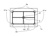
- FIG. 9A is a plan view showing a main portion of a hydrostatic gas bearing device according to yet another embodiment of the present disclosure.
- another porous body 3a and another first groove 41a located on the other porous body 3a may be located in the middle of the first intersecting groove 51. Even in such a case, it can be said that the first intersecting groove 51 connects adjacent second grooves 42.
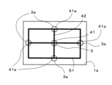
- FIG. 9B is a plan view showing a main portion of a hydrostatic gas bearing device according to yet another embodiment of the present disclosure.
- another porous body 3a and another first groove 41a located on the other porous body 3a may be located at the connection between the second groove 42 and the first intersecting groove 51. Even in such a case, it can be said that the first intersecting groove 51 intersects with the second groove 42.
- FIG. 10 is a plan view showing the main parts of a hydrostatic gas bearing device according to yet another embodiment of the present disclosure.
- the hydrostatic gas bearing device of FIG. 10 can be said to have a porous body 3, a first groove 41 located on the porous body 3, a second groove 42 communicating with the first groove 41, and a first intersecting groove 51 intersecting the second groove 42.
- another porous body 3a and another first groove 41a located on the porous body 3a can be said to be located at the connection between the second groove 42 and the first intersecting groove 51. Even with this configuration, the buoyancy of the movable member 1 is stabilized and micro-vibrations are reduced.
- FIG. 11A is a plan view showing a main portion of a hydrostatic gas bearing device according to yet another embodiment of the present disclosure.
- the hydrostatic gas bearing device of FIG. 11A has a porous body 3, a first groove 41 located on the porous body 3, a second groove 42 communicating with the first groove 41, and a first intersecting groove 51 intersecting the second groove 42.
- the first intersecting groove 51 does not have to have an annular structure.
- FIG. 11B is a plan view showing the main parts of a hydrostatic gas bearing device according to yet another embodiment of the present disclosure.
- another porous body 3a and another first groove 41a located on the other porous body 3a are located at the end of the first intersecting groove 51 in the hydrostatic gas bearing device of FIG. 11A. Even in such a case, it can be said that the first intersecting groove 51 intersects with the second groove 42. Even with the configurations shown in FIGS. 11A and 11B, the buoyancy of the movable member 1 is stabilized and micro-vibrations are reduced.
- hydrostatic gas bearing device according to the present disclosure will be specifically explained using examples and comparative examples, but the hydrostatic gas bearing device according to the present disclosure is not limited to the examples below.
- Example 1 First, an aerostatic bearing device was fabricated as shown in Fig. 1.
- the movable member 1 included in the aerostatic bearing device of Example 1 was made of alumina with a purity of 99.5 mass%.
- the dimensions of the four bearing surfaces 1a were each 100 mm in width and 100 mm in length in the moving direction.
- Each of the four bearing surfaces 1a includes one unit including a porous body 3, a first groove 41, a second groove 42, and a first intersecting groove 51 as shown in FIG. 2A.
- the second groove 42 and the first intersecting groove 51 each have a width of 1 mm and a depth of 0.02 mm.
- the first intersecting groove 51 has a square ring-shaped structure when viewed in a plan view.
- the length of the first intersecting groove 51 in the direction perpendicular to the moving direction of the movable member 1 is 50 mm, and the length in the moving direction of the movable member 1 is 50 mm.
- the porous body 3 is made of alumina, and is made using alumina with a purity of 99.5% by mass, with an average particle size of 80 ⁇ m and a porosity of 40%.
- the porous body 3 has a diameter of 10 mm.
- the first groove 41 located in the porous body 3 has a width of 1 mm and a depth of 0.02 mm.
- the fixed member 2 included in the hydrostatic gas bearing device of Example 1 is made of alumina with a purity of 99.5% by mass.
- the vertical and horizontal lengths of the fixed member 2 are 80 mm, and the length in the longitudinal direction (the length in the direction in which the movable member 1 moves) is 300 mm.
- Example 1 An aerostatic bearing device was produced in the same manner as in Example 1, except that an orifice restrictor having an opening diameter of 0.2 mm was used instead of the porous body 3 used in Example 1.
- the hydrostatic gas bearing device of Example 1 had the same rigidity as the hydrostatic gas bearing device of Comparative Example 1. On the other hand, the hydrostatic gas bearing device of Example 1 was able to reduce micro-vibrations to about 1/10 of those of the hydrostatic gas bearing device of Comparative Example 1.
- the hydrostatic gas bearing device comprises a movable member and a fixed member.
- a recess is located on the bearing surface of the base of the movable member or the fixed member, and the opening of the gas supply hole is located on the bottom surface of the recess.
- a porous body that serves as a gas outlet is located in the recess so as not to protrude from the bearing surface.
- a first groove is located on the surface of the porous body, extending from the central region of the surface to the outer periphery of the porous body.
- a second groove that communicates with the first groove is located on the bearing surface of the base.
- a first intersecting groove is positioned on the bearing surface so as to intersect with the second groove.
- at least two second grooves are positioned, and the first intersecting groove connects adjacent second grooves to each other.
- the first intersecting groove is annular.
- the surface of the porous body and the bearing surface of the base are flush with each other.
- the porous body is made of the same material as the member in which the recess is located.
- the porous body In the hydrostatic gas bearing device according to any one of (1) to (6) above, at least the bottom surface of the porous body is bonded to the recess. (8) In the hydrostatic gas bearing device described in (7) above, the porous body is bonded to the entire surface of the recess other than the opening of the gas supply hole. (9) In the hydrostatic gas bearing device described in any one of (1) to (8) above, at least two first grooves are positioned, and the angles formed by two adjacent first grooves are the same. (10) In the hydrostatic gas bearing device according to any one of (1) to (9) above, the porous body further includes second intersecting grooves that intersect with the first grooves.
- a plurality of recesses are located on the bearing surface, and a plurality of porous bodies are located in each of the plurality of recesses.
- a first groove located in the porous body, a second groove communicating with the first groove, and a first intersecting groove intersecting the second groove are considered to be one unit, a plurality of units are located on the bearing surface, and adjacent units are connected by sharing at least a portion of the second groove or at least a portion of the first intersecting groove.
Landscapes
- Engineering & Computer Science (AREA)
- General Engineering & Computer Science (AREA)
- Physics & Mathematics (AREA)
- General Physics & Mathematics (AREA)
- Mechanical Engineering (AREA)
- Magnetic Bearings And Hydrostatic Bearings (AREA)
Priority Applications (2)
| Application Number | Priority Date | Filing Date | Title |
|---|---|---|---|
| KR1020257013359A KR20250075657A (ko) | 2022-10-26 | 2023-10-24 | 정압 기체 베어링 장치 |
| JP2024553086A JPWO2024090442A1 (https=) | 2022-10-26 | 2023-10-24 |
Applications Claiming Priority (2)
| Application Number | Priority Date | Filing Date | Title |
|---|---|---|---|
| JP2022171335 | 2022-10-26 | ||
| JP2022-171335 | 2022-10-26 |
Publications (1)
| Publication Number | Publication Date |
|---|---|
| WO2024090442A1 true WO2024090442A1 (ja) | 2024-05-02 |
Family
ID=90830837
Family Applications (1)
| Application Number | Title | Priority Date | Filing Date |
|---|---|---|---|
| PCT/JP2023/038377 Ceased WO2024090442A1 (ja) | 2022-10-26 | 2023-10-24 | 静圧気体軸受装置 |
Country Status (3)
| Country | Link |
|---|---|
| JP (1) | JPWO2024090442A1 (https=) |
| KR (1) | KR20250075657A (https=) |
| WO (1) | WO2024090442A1 (https=) |
Citations (4)
| Publication number | Priority date | Publication date | Assignee | Title |
|---|---|---|---|---|
| JPH03244827A (ja) * | 1990-02-21 | 1991-10-31 | Nippon Seiko Kk | 静圧気体軸受 |
| JP2003232352A (ja) * | 2002-02-06 | 2003-08-22 | Nikon Corp | エアパッド、このエアパッドを用いたステージ装置及びこのステージ装置を備える露光装置 |
| JP2011149500A (ja) * | 2010-01-22 | 2011-08-04 | Sintokogio Ltd | 静圧軸受装置および静圧軸受装置を備えたステージ |
| CN110848258A (zh) * | 2019-12-16 | 2020-02-28 | 江苏集萃精凯高端装备技术有限公司 | 一种气体静压气浮垫及气浮导轨 |
Family Cites Families (1)
| Publication number | Priority date | Publication date | Assignee | Title |
|---|---|---|---|---|
| JPH0510330A (ja) | 1991-06-29 | 1993-01-19 | Canon Inc | 静圧軸受装置 |
-
2023
- 2023-10-24 WO PCT/JP2023/038377 patent/WO2024090442A1/ja not_active Ceased
- 2023-10-24 KR KR1020257013359A patent/KR20250075657A/ko active Pending
- 2023-10-24 JP JP2024553086A patent/JPWO2024090442A1/ja active Pending
Patent Citations (4)
| Publication number | Priority date | Publication date | Assignee | Title |
|---|---|---|---|---|
| JPH03244827A (ja) * | 1990-02-21 | 1991-10-31 | Nippon Seiko Kk | 静圧気体軸受 |
| JP2003232352A (ja) * | 2002-02-06 | 2003-08-22 | Nikon Corp | エアパッド、このエアパッドを用いたステージ装置及びこのステージ装置を備える露光装置 |
| JP2011149500A (ja) * | 2010-01-22 | 2011-08-04 | Sintokogio Ltd | 静圧軸受装置および静圧軸受装置を備えたステージ |
| CN110848258A (zh) * | 2019-12-16 | 2020-02-28 | 江苏集萃精凯高端装备技术有限公司 | 一种气体静压气浮垫及气浮导轨 |
Also Published As
| Publication number | Publication date |
|---|---|
| JPWO2024090442A1 (https=) | 2024-05-02 |
| KR20250075657A (ko) | 2025-05-28 |
Similar Documents
| Publication | Publication Date | Title |
|---|---|---|
| KR101267442B1 (ko) | 정압 베어링 장치 및 정압 베어링 장치를 구비한 스테이지 | |
| CN101435466A (zh) | 一种多孔质气体静压止推轴承 | |
| JP2018526640A (ja) | 気体軸受を備えるレオメータ | |
| JP6779915B2 (ja) | バルブユニットを備える流体流動装置、および、その製造方法 | |
| JPH09296825A (ja) | 静圧気体軸受 | |
| WO2024090442A1 (ja) | 静圧気体軸受装置 | |
| JP2025154418A (ja) | 静圧気体軸受装置 | |
| WO2002012742A2 (en) | Hydrostatic gas bearing | |
| JP3660779B2 (ja) | 静圧気体軸受装置 | |
| JP2006029412A (ja) | 静圧形直動案内ユニット | |
| Kim et al. | The fabrication of flow conduits in ceramic tapes and the measurement of fluid flow through these conduits | |
| US12429090B2 (en) | Gas restriction structure constituting aerostatic bearing, and aerostatic bearing | |
| JP2013185623A (ja) | 直動浮上装置 | |
| JP2025131394A (ja) | 流体軸受、装置、ステージ、スピンドル、流体軸受の製造方法、物品の製造方法 | |
| JP7496661B2 (ja) | セラミック接合体およびその製造方法 | |
| JP4463049B2 (ja) | セラミック構造体とこれを用いた位置決め装置用部材 | |
| CN116292630B (zh) | 一种全狭缝节流静压气体支承径向止推轴承 | |
| JP4875296B2 (ja) | 静圧気体軸受パッド | |
| CN112922961B (zh) | 基于多孔质节流单元的静压气浮单元及加工方法 | |
| US12110921B2 (en) | Ultra-low profile aerostatic bearing and the method of manufacturing the same | |
| JPH06193635A (ja) | 静圧軸受装置 | |
| TWI571571B (zh) | 空氣軸承改良構造 | |
| JP5127624B2 (ja) | スライド装置およびそれを用いた処理システム | |
| JP4417189B2 (ja) | ハニカム構造体 |
Legal Events
| Date | Code | Title | Description |
|---|---|---|---|
| 121 | Ep: the epo has been informed by wipo that ep was designated in this application |
Ref document number: 23882647 Country of ref document: EP Kind code of ref document: A1 |
|
| WWE | Wipo information: entry into national phase |
Ref document number: 2024553086 Country of ref document: JP |
|
| ENP | Entry into the national phase |
Ref document number: 20257013359 Country of ref document: KR Kind code of ref document: A |
|
| WWE | Wipo information: entry into national phase |
Ref document number: 1020257013359 Country of ref document: KR |
|
| NENP | Non-entry into the national phase |
Ref country code: DE |
|
| 122 | Ep: pct application non-entry in european phase |
Ref document number: 23882647 Country of ref document: EP Kind code of ref document: A1 |