WO2024090442A1 - Hydrostatic gas bearing device - Google Patents
Hydrostatic gas bearing device Download PDFInfo
- Publication number
- WO2024090442A1 WO2024090442A1 PCT/JP2023/038377 JP2023038377W WO2024090442A1 WO 2024090442 A1 WO2024090442 A1 WO 2024090442A1 JP 2023038377 W JP2023038377 W JP 2023038377W WO 2024090442 A1 WO2024090442 A1 WO 2024090442A1
- Authority
- WO
- WIPO (PCT)
- Prior art keywords
- groove
- porous body
- bearing device
- hydrostatic gas
- gas bearing
- Prior art date
Links
- 230000002706 hydrostatic effect Effects 0.000 title claims abstract description 87
- 238000004891 communication Methods 0.000 claims abstract description 6
- 239000000463 material Substances 0.000 claims description 6
- 239000000919 ceramic Substances 0.000 description 9
- PNEYBMLMFCGWSK-UHFFFAOYSA-N aluminium oxide Inorganic materials [O-2].[O-2].[O-2].[Al+3].[Al+3] PNEYBMLMFCGWSK-UHFFFAOYSA-N 0.000 description 6
- 238000000034 method Methods 0.000 description 6
- 230000000052 comparative effect Effects 0.000 description 5
- 238000005259 measurement Methods 0.000 description 5
- QSHDDOUJBYECFT-UHFFFAOYSA-N mercury Chemical compound [Hg] QSHDDOUJBYECFT-UHFFFAOYSA-N 0.000 description 5
- 229910052753 mercury Inorganic materials 0.000 description 5
- MCMNRKCIXSYSNV-UHFFFAOYSA-N Zirconium dioxide Chemical compound O=[Zr]=O MCMNRKCIXSYSNV-UHFFFAOYSA-N 0.000 description 4
- 238000010586 diagram Methods 0.000 description 4
- 230000000694 effects Effects 0.000 description 3
- 238000002459 porosimetry Methods 0.000 description 3
- 239000004065 semiconductor Substances 0.000 description 3
- 229910052581 Si3N4 Inorganic materials 0.000 description 2
- 230000006835 compression Effects 0.000 description 2
- 238000007906 compression Methods 0.000 description 2
- PMHQVHHXPFUNSP-UHFFFAOYSA-M copper(1+);methylsulfanylmethane;bromide Chemical compound Br[Cu].CSC PMHQVHHXPFUNSP-UHFFFAOYSA-M 0.000 description 2
- 238000006073 displacement reaction Methods 0.000 description 2
- 239000012530 fluid Substances 0.000 description 2
- 238000009616 inductively coupled plasma Methods 0.000 description 2
- 238000004519 manufacturing process Methods 0.000 description 2
- 229910052751 metal Inorganic materials 0.000 description 2
- 239000002184 metal Substances 0.000 description 2
- 150000002739 metals Chemical class 0.000 description 2
- 239000002245 particle Substances 0.000 description 2
- 239000002243 precursor Substances 0.000 description 2
- HBMJWWWQQXIZIP-UHFFFAOYSA-N silicon carbide Chemical compound [Si+]#[C-] HBMJWWWQQXIZIP-UHFFFAOYSA-N 0.000 description 2
- 229910010271 silicon carbide Inorganic materials 0.000 description 2
- HQVNEWCFYHHQES-UHFFFAOYSA-N silicon nitride Chemical compound N12[Si]34N5[Si]62N3[Si]51N64 HQVNEWCFYHHQES-UHFFFAOYSA-N 0.000 description 2
- 229920003319 Araldite® Polymers 0.000 description 1
- 238000002441 X-ray diffraction Methods 0.000 description 1
- 229910052782 aluminium Inorganic materials 0.000 description 1
- XAGFODPZIPBFFR-UHFFFAOYSA-N aluminium Chemical compound [Al] XAGFODPZIPBFFR-UHFFFAOYSA-N 0.000 description 1
- 238000004458 analytical method Methods 0.000 description 1
- 229920006332 epoxy adhesive Polymers 0.000 description 1
- 238000012986 modification Methods 0.000 description 1
- 230000004048 modification Effects 0.000 description 1
- 238000005498 polishing Methods 0.000 description 1
- 239000011148 porous material Substances 0.000 description 1
- 230000005855 radiation Effects 0.000 description 1
- 238000004439 roughness measurement Methods 0.000 description 1
- 229910001220 stainless steel Inorganic materials 0.000 description 1
- 239000010935 stainless steel Substances 0.000 description 1
- 230000003746 surface roughness Effects 0.000 description 1
- 238000004876 x-ray fluorescence Methods 0.000 description 1
Images


Classifications
-
- F—MECHANICAL ENGINEERING; LIGHTING; HEATING; WEAPONS; BLASTING
- F16—ENGINEERING ELEMENTS AND UNITS; GENERAL MEASURES FOR PRODUCING AND MAINTAINING EFFECTIVE FUNCTIONING OF MACHINES OR INSTALLATIONS; THERMAL INSULATION IN GENERAL
- F16C—SHAFTS; FLEXIBLE SHAFTS; ELEMENTS OR CRANKSHAFT MECHANISMS; ROTARY BODIES OTHER THAN GEARING ELEMENTS; BEARINGS
- F16C32/00—Bearings not otherwise provided for
- F16C32/06—Bearings not otherwise provided for with moving member supported by a fluid cushion formed, at least to a large extent, otherwise than by movement of the shaft, e.g. hydrostatic air-cushion bearings
-
- G—PHYSICS
- G03—PHOTOGRAPHY; CINEMATOGRAPHY; ANALOGOUS TECHNIQUES USING WAVES OTHER THAN OPTICAL WAVES; ELECTROGRAPHY; HOLOGRAPHY
- G03F—PHOTOMECHANICAL PRODUCTION OF TEXTURED OR PATTERNED SURFACES, e.g. FOR PRINTING, FOR PROCESSING OF SEMICONDUCTOR DEVICES; MATERIALS THEREFOR; ORIGINALS THEREFOR; APPARATUS SPECIALLY ADAPTED THEREFOR
- G03F7/00—Photomechanical, e.g. photolithographic, production of textured or patterned surfaces, e.g. printing surfaces; Materials therefor, e.g. comprising photoresists; Apparatus specially adapted therefor
- G03F7/20—Exposure; Apparatus therefor
-
- H—ELECTRICITY
- H01—ELECTRIC ELEMENTS
- H01L—SEMICONDUCTOR DEVICES NOT COVERED BY CLASS H10
- H01L21/00—Processes or apparatus adapted for the manufacture or treatment of semiconductor or solid state devices or of parts thereof
- H01L21/02—Manufacture or treatment of semiconductor devices or of parts thereof
- H01L21/027—Making masks on semiconductor bodies for further photolithographic processing not provided for in group H01L21/18 or H01L21/34
-
- H—ELECTRICITY
- H01—ELECTRIC ELEMENTS
- H01L—SEMICONDUCTOR DEVICES NOT COVERED BY CLASS H10
- H01L21/00—Processes or apparatus adapted for the manufacture or treatment of semiconductor or solid state devices or of parts thereof
- H01L21/67—Apparatus specially adapted for handling semiconductor or electric solid state devices during manufacture or treatment thereof; Apparatus specially adapted for handling wafers during manufacture or treatment of semiconductor or electric solid state devices or components ; Apparatus not specifically provided for elsewhere
- H01L21/683—Apparatus specially adapted for handling semiconductor or electric solid state devices during manufacture or treatment thereof; Apparatus specially adapted for handling wafers during manufacture or treatment of semiconductor or electric solid state devices or components ; Apparatus not specifically provided for elsewhere for supporting or gripping
Definitions
- This disclosure relates to a hydrostatic gas bearing device.
- air slides are used as devices for scanning and positioning stages with high precision.
- Examples of such air slides include those that use orifice diaphragms and surface diaphragms. With such air slides, if foreign matter gets into the gas supply hole, the amount of gas supplied changes, reducing rigidity and making the dynamic posture of the moving body unstable.
- a hydrostatic bearing device is used in which a porous member is provided in the bearing section, and the porous member is provided with an air supply hole and an exhaust groove for exhausting the pressurized fluid.
- the hydrostatic bearing device described in Patent Document 1 can increase the area in which compressed gas is ejected. As a result, the bearing rigidity can be increased, but there is an issue that vibrations are generated due to the compression effect of the gas within the porous body.
- the hydrostatic gas bearing device comprises a movable member and a fixed member.
- a recess is located on the bearing surface of the base of the movable member or the fixed member, and the opening of the gas supply hole is located on the bottom surface of the recess.
- a porous body that serves as the gas outlet is located in the recess so as not to protrude from the bearing surface.
- a first groove is located on the surface of the porous body, extending from the central region of the surface to the outer periphery of the porous body.
- a second groove that communicates with the first groove is located on the bearing surface of the base.
- FIG. 1 is an explanatory diagram showing an example in which a hydrostatic gas bearing device according to an embodiment of the present disclosure is provided in a linear guide device.
- 1 is a plan view showing a main portion of an externally pressurized gas bearing device according to an embodiment of the present disclosure.
- FIG. 11 is a plan view showing a modified example of a main part of an externally pressurized gas bearing device according to an embodiment of the present disclosure.
- FIG. 11 is a plan view showing another modified example of the main part of the hydrostatic gas bearing device according to an embodiment of the present disclosure.
- FIG. 2B is an explanatory diagram showing a cross section taken along line XX in FIG. 2A.
- FIG. 4 is a plan view showing the bottom surface of the recessed portion.
- FIG. 11 is a plan view showing a main portion of a hydrostatic gas bearing device according to another embodiment of the present disclosure.
- FIG. 13 is a plan view showing a main portion of a hydrostatic gas bearing device according to still another embodiment of the present disclosure.
- FIG. 13 is a plan view showing a main portion of a hydrostatic gas bearing device according to still another embodiment of the present disclosure.
- FIG. 11 is a plan view showing a main portion of a hydrostatic gas bearing device according to still another embodiment of the present disclosure.
- FIG. 13 is a plan view showing a main portion of a hydrostatic gas bearing device according to still another embodiment of the present disclosure.
- FIG. 13 is a plan view showing a main portion of a hydrostatic gas bearing device according to still another embodiment of the present disclosure.
- FIG. 13 is a plan view showing a main portion of a hydrostatic gas bearing device according to still another embodiment of the present disclosure.
- FIG. 13 is a plan view showing a main portion of a hydrostatic gas bearing device according to still
- FIG. 13 is a plan view showing a main portion of a hydrostatic gas bearing device according to still another embodiment of the present disclosure.
- FIG. 13 is a plan view showing a main portion of a hydrostatic gas bearing device according to still another embodiment of the present disclosure.
- FIG. 13 is a plan view showing a main portion of a hydrostatic gas bearing device according to still another embodiment of the present disclosure.
- the hydrostatic gas bearing device disclosed herein has the above-mentioned configuration, which makes it possible to reduce the decrease in rigidity caused by micro-vibrations and clogging of the gas supply holes.
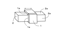
- FIG. 1 is an explanatory diagram showing an example in which a hydrostatic gas bearing device according to one embodiment of the present disclosure is provided on a linear guide device.
- the hydrostatic gas bearing device according to one embodiment includes a movable member 1 and a fixed member 2.
- the movable member 1 is arranged to surround the fixed member 2, which has a roughly rectangular prism shape.
- the movable member 1 and the fixed member 2 are positioned with a gap between them, and are not in contact.
- a hydrostatic gas layer is formed by ejecting compressed gas from the bearing surface 1a of the base of the movable member 1 or the bearing surface 2a of the base of the fixed member 2. Therefore, with the movable member 1 and the fixed member 2 in a non-contact state, the movable member 1 can be moved along the fixed member 2 using a separate driving means (not shown).
- the movable member 1 and the fixed member 2 are formed, for example, from ceramics or metals.
- ceramics forming the movable member 1 and the fixed member 2 include ceramics whose main components are alumina, zirconia, silicon carbide, silicon nitride, or aluminum nitride.
- metals include aluminum and stainless steel.
- the movable member 1 and the fixed member 2 may be formed from the same material or different materials.
- main component means a component that accounts for 80% or more by mass out of a total of 100% by mass of the components that make up the ceramic.
- Each component contained in the ceramic is identified using an X-ray diffraction device that uses CuK ⁇ radiation, and the content of each component can be determined, for example, using an ICP (Inductively Coupled Plasma) emission spectrometer or an X-ray fluorescence analyzer.
- ICP Inductively Coupled Plasma
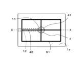
- Figure 2A is a plan view showing the main parts of a hydrostatic gas bearing device according to one embodiment of the present disclosure.
- Figure 3 is an explanatory diagram showing a cross section taken along line X-X in Figure 2A.
- Figure 4 is a plan view showing the bottom surface 11a of the recess 11. As shown in Figures 2A to 4, the bearing surface 1a of the base of the movable member 1 is provided with the recess 11 and a gas supply hole 12 having an opening 12a in part of the bottom surface 11a of the recess 11.
- the porous body 3 is located in the recess 11.
- the depth of the recess 11 is not limited, and is, for example, 1 mm or more and 10 mm or less.
- the porous body 3 is a member that serves as the gas ejection portion.
- the porous body 3 is fixed to the recess 11 so as not to protrude from the bearing surface 1a of the base of the movable member 1.
- a gas supply hole 12 that communicates with the outside of the movable member 1 is connected to the bottom surface 11a of the recess 11.
- the gas supply hole 12 has an opening 12a in part of the bottom surface 11a of the recess 11. Gas is supplied from the outside of the movable member 1 through the gas supply hole 12 to the porous body 3 that serves as the ejection part.
- the gas supply hole 12 may be, for example, a horizontal hole formed from the side surface of the base, a vertical hole formed from the bottom surface of the base, or a combination of a horizontal hole formed from the side surface of the base and a vertical hole connecting the horizontal hole and the bottom surface 11a.
- the porous body 3 is made of, for example, ceramics. Examples of such ceramics include ceramics mainly composed of alumina, zirconia, silicon carbide, silicon nitride, or aluminum nitride.
- the porous body 3 may be made of the same material as the member in which the recess 11 is located (in one embodiment, the movable member 1). When the porous body 3 is made of the same material as the member in which the recess 11 is located, differences in thermal expansion coefficients are unlikely to occur and stress is unlikely to occur even when the temperature changes. Therefore, turbulence is unlikely to occur due to deformation, etc., and micro-vibrations due to turbulence are further reduced.
- the porosity of the porous body 3 is not limited and may be, for example, 20% to 50%.
- the average particle size of the porous body 3 is not limited and may be, for example, 10 ⁇ m to 100 ⁇ m.
- the porosity of the porous body 3 can be determined, for example, by mercury intrusion porosimetry.
- Mercury intrusion porosimetry is a method in which mercury is injected (mercury intrusion porosimetry) into the pores of the porous body 3 (sample) using a mercury intrusion porosimeter to determine the porosity, and can be determined in accordance with JIS R 1655-2003.
- the thickness of the porous body 3 is not limited as long as it does not protrude from the recess 11.
- the upper surface of the porous body 3 and the bearing surface of the base in one embodiment, the bearing surface 1a of the base of the movable member 1 may be flush.
- turbulence due to the step between the upper surface of the porous body 3 and the bearing surface of the base is less likely to occur. As a result, micro-vibrations caused by turbulence are further reduced.
- At least the bottom surface of the porous body 3 may be bonded to the bottom surface 11a of the recess 11.
- the fixing strength of the porous body 3 can be increased.
- the bonding method is not limited, and for example, the porous body 3 may be bonded using an epoxy adhesive such as Araldite (registered trademark, manufactured by Huntsman Japan) and Thor Seal (manufactured by Agilent).
- the porous body 3 may be bonded to the entire surface of the recess 11 other than the opening 12a of the gas supply hole 12.
- the gas flows more easily from the gas supply hole 12 to the first groove 41 described later. As a result, the gas is more easily dispersed throughout the porous body 3, and micro-vibrations are further reduced.
- the surface of the porous body 3 is provided with a plurality of radial first grooves 41.
- the first grooves 41 are formed from the central region of the porous body 3 toward the outside, as shown in FIG. 2A.
- the number of first grooves 41 may be three or more and eight or less.
- the width and depth of the first grooves 41 are not limited. The width may be, for example, 0.5 mm or more and 2 mm or less. The depth may be, for example, 0.005 mm or more and 0.05 mm or less.
- the cross-sectional shape perpendicular to the length direction of the first groove 41 is not particularly limited.
- This cross-sectional shape may be, for example, a U-shape in which the opening and bottom of the groove are the same width, or a V-shape in which the opening width of the groove is larger than the bottom width, or a U-shape (shape with a curved bottom).
- the groove may be a V-shape or a U-shape in which the opening width of the groove is larger than the bottom width.
- the width is smaller than the depth. Therefore, since losses due to resistance are likely to be large, it is better for the width of the groove to be larger than the depth. However, if the depth is too large compared to the width, micro-vibrations are likely to increase. Therefore, the width should be 100 times or less than the depth.
- the angles formed by two adjacent first grooves 41 in a plurality of first grooves 41 may have the same angle. With such a configuration, the gas flowing through the first grooves 41 becomes more uniform. As a result, the variation in the gas flow is reduced.
- four first grooves 41 are formed at intervals of 90°.
- the bearing surface of the base (in one embodiment, the bearing surface 1a of the base of the movable member 1) is provided with a plurality of second grooves 42 that communicate with the first grooves 41.
- the second groove 42 is connected to the first groove 41, and is therefore positioned in a straight line with the first groove 41, as shown in FIG. 2A.
- the width and depth of the second groove 42 are, for example, the same as the width and depth of the first groove 41.
- the hydrostatic gas bearing device has a first groove 41 and a second groove 42. Therefore, the gas ejected from the porous body 3 can be moved to the second groove 42 by the first groove 41. As a result, the gas can be moved to the base of the movable member 1. Therefore, a buoyancy force can be generated in the base of the movable member 1, and the buoyancy force is stabilized, reducing micro-vibrations.
- the bearing surface 1a of the base may be provided with a first intersecting groove 51 that intersects with the second groove 42.
- the gas flowing through the second groove 42 can be dispersed in a direction that intersects with the second groove 42, further reducing micro-vibrations.
- Examples of "intersecting” include two-crossing, three-crossing, and four-crossing.
- Two-crossing means a structure that faces in two directions from an intersection, such as an L-shape.
- Three-crossing means a structure that faces in three directions from an intersection, such as a T-shape and a Y-shape.
- Four-crossing means a structure that faces in four directions from an intersection, such as a cross shape, an X-shape, and a swastika shape.
- the first intersecting groove 51 may be connected at the end of the second groove 42, or may be connected midway through the second groove 42.
- the first intersecting groove 51 may be connected at its end to the second groove 42, or may be connected midway through the first intersecting groove 51 to the second groove 45.
- the first intersecting groove 51 may connect adjacent second grooves 45. This makes it easier to supply gas uniformly to the bearing surface 1a.
- the first intersecting groove 51 is positioned so as to connect the ends of the second grooves 42.
- the first intersecting groove 51 is formed in a rectangular shape to match the rectangular bearing surface 1a when viewed in a plan view. In this way, it is preferable to form the first intersecting groove 51 parallel to the outer shape of the bearing surface 1a.
- the shape of the first intersecting groove 51 is not limited as long as it is formed so as to connect the second grooves 42.
- the first intersecting groove 51 may be formed in a ring shape so as to connect the second grooves 42 together, as shown in FIG. 2A.
- the first intersecting groove 51 may be similar in shape to the bearing surface 1a of the base (if the bearing surface 1a is rectangular as shown in FIG. 2A, the first intersecting groove 51 may be rectangular). This makes it easier for gas to be supplied uniformly to the bearing surface 1a.
- the width and depth of the first intersecting groove 51 are, for example, the same as the width and depth of the first groove 41.
- FIG. 2A is formed in an annular shape so as to connect the ends of the second grooves 42.
- the first intersecting groove 51 may be formed in an annular shape so as to connect portions other than the ends of the second grooves 42.
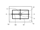
- FIG. 2B is a plan view showing a modified example of a main part of a hydrostatic gas bearing device according to an embodiment of the present disclosure.
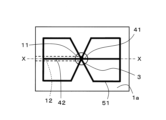
- FIG. 2C is a plan view showing another modified example of the main part of the hydrostatic gas bearing device according to one embodiment of the present disclosure.
- the porous body 3 may further be provided with at least one second intersecting groove 52 that intersects and connects with the first groove 41.
- FIG. 5 is a plan view showing a main portion of a hydrostatic gas bearing device according to another embodiment of the present disclosure. By providing the second intersecting groove 52, the variation in the gas flow is reduced. The second intersecting groove 52 may connect between a plurality of first grooves 41. This makes it easier for gas to be supplied uniformly to the surface of the porous body 3.
- the second intersecting groove 52 may have a similar shape to the porous body 3 when viewed in a plan view.
- the porous body 3 has a circular shape when viewed in a plan view
- the second intersecting groove 52 also has a circular shape (annular shape).
- the second intersecting groove 52 has a circular shape (annular shape).
- the second intersecting groove 52 is not limited to annular shape as long as it has a shape that can connect the first grooves 41.
- the arithmetic mean roughness Ra of the bearing surface of the base (bearing surface 1a of the base of the movable member 1), the surface of the porous body 3, and the inner wall surface of each groove is not limited.
- the arithmetic mean roughness Ra of the bearing surface of the base may be smaller than the arithmetic mean roughness Ra of the inner wall surface of the second groove 42. If the arithmetic mean roughness Ra of the bearing surface of the base is smaller than the arithmetic mean roughness Ra of the inner wall surface of the second groove 42, the inner wall surface of the second groove 42 is relatively rough and can slow down the speed of the flowing gas. As a result, vibrations are absorbed and micro-vibrations are reduced.
- the bearing surface of the base is relatively smooth. Therefore, the gas can easily spread evenly over the bearing surface (bearing surface 1a), allowing the movable member 1 to move smoothly.
- the arithmetic mean roughness Ra of the surface of the porous body 3 may be smaller than the arithmetic mean roughness Ra of the inner wall surface of the first groove 41.
- the inner wall surface of the first groove 41 is relatively rough and can slow down the speed of the flowing gas. As a result, vibrations are absorbed and micro-vibrations are reduced.
- the surface of the porous body 3 is relatively smooth. Therefore, the gas can easily spread evenly over the surface of the porous body 3, allowing the movable member 1 to move smoothly.
- the arithmetic mean roughness Ra of the bearing surface of the base may be, for example, 0.1 ⁇ m or more and 1.0 ⁇ m or less.
- the arithmetic mean roughness Ra of the surface of the porous body 3 may be, for example, 0.1 ⁇ m or more and 2.0 ⁇ m or less.
- the arithmetic mean roughness Ra of the inner wall surface of the first groove 41 may be, for example, 0.5 ⁇ m or more and 3.0 ⁇ m or less.
- the arithmetic mean roughness Ra of the inner wall surface of the second groove 42 may be, for example, 1.0 ⁇ m or more and 4.0 ⁇ m or less.
- the arithmetic mean roughness Ra of the bearing surface of the base, the surface of the porous body 3, and the inner wall surface of each groove can be measured in accordance with JIS B 0601:2001 using a shape analysis laser microscope (Keyence Corporation, VK-X1100 or its successor model). Measurement conditions are a measurement magnification of 240x, no cutoff value ⁇ s, a cutoff value ⁇ c of 0.08mm, and no cutoff value fs.
- the measurement range on one surface to be measured is 1420 ⁇ m ⁇ 1070 ⁇ m, and four measurement ranges are set on each surface to be measured. Four lines to be measured are drawn at approximately equal intervals in each measurement range, and surface roughness measurements are performed. The length of each line to be measured is 1320 ⁇ m.
- the cross-sectional area of the first groove 41 may be the same as or larger than the cross-sectional area of the second groove 42.
- the porous body 3 tends to have high pressure and high airflow resistance due to the squeezing effect of the fine holes (molecules are compressed by passing a fluid through fine holes). Therefore, by having grooves on the surface of the porous body 3 as described above, the airflow resistance of the first groove 41 can be reduced and gas can be smoothly supplied to the second groove 42.
- the cross-sectional areas of the first groove 41 and the second groove 42 can be set to the desired cross-sectional area by changing at least one of the depth and width of each groove.
- the cross-sectional area of the first groove 41 means the area of the region surrounded by an imaginary plane passing through the surface of the porous body 3 and the inner wall of the first groove 41 in a cross section of the first groove 41 cut perpendicular to its extension direction.
- the cross-sectional area of the second groove 42 means the area of the region surrounded by an imaginary plane passing through the bearing surface of the base and the inner wall of the second groove 42 in a cross section of the second groove 42 cut perpendicular to its extension direction.
- FIG. 6 is a plan view showing a main portion of a hydrostatic gas bearing device according to yet another embodiment of the present disclosure.
- a first groove 41 provided in the porous body 3 a second groove 42 communicating with the first groove 41, and a first intersecting groove 51 intersecting with the second groove 42 are considered as one unit, the units are located in multiple positions on the bearing surface 1a, and each unit may be located independently so that they do not come into contact with each other.
- FIG. 7 is a plan view showing a main portion of a hydrostatic gas bearing device according to yet another embodiment of the present disclosure.
- the variation in the gas flow in each unit is reduced. As a result, the gas tends to spread evenly across the bearing surface (bearing surface 1a).
- adjacent units may be connected to each other by sharing a shared groove 54 between a part of the first intersecting groove 51 that is part of one unit and a part of the first intersecting groove 51 that is part of the other unit.
- a part of the first intersecting groove 51 of one of the adjacent units may include a shared groove 54
- a part of the first intersecting groove 51 of the other unit may also include this shared groove 54.
- the method for forming the first groove 41 and the second intersecting groove 52 on the surface of the porous body 3, and the method for forming the second groove 42, the first intersecting groove 51 and the communicating groove 53 on the bearing surface of the base (bearing surface 1a of the base of the movable member 1) are not limited as long as they are methods that form grooves.
- the grooves may be formed by grinding or polishing, or the grooves may be formed in advance when the porous body 3 and the base are produced.
- a method for forming the grooves in advance is to obtain a precursor (molded body) in which the portions that will become the grooves are formed, and then sinter this precursor.
- the porous body 3 may be fixed to the recess 11 of the base, and then the grooves may be formed.
- the first groove 41 and the second groove 42 that communicates with the first groove 41 are integrally formed. This improves the positional accuracy of the first groove 41 and the second groove 42.
- the hydrostatic gas bearing device is not limited to the hydrostatic gas bearing device according to the above-mentioned embodiment.
- a first intersecting groove 51 is provided that connects the ends of the second grooves 42.
- a further intersecting groove may be provided between the first intersecting groove and the porous body. This further intersecting groove only needs to be provided around at least one circumference, and may be provided in a concentric ring shape with the first intersecting groove.
- each unit including one porous body 3, a first groove 41 provided in the porous body 3, a second groove 42 communicating with the first groove 41, and a first intersecting groove 51 connecting the ends of the second groove 42.
- the units may be positioned in a straight line, in a vertical and horizontal grid pattern, or randomly.
- FIG. 9A is a plan view showing a main portion of a hydrostatic gas bearing device according to yet another embodiment of the present disclosure.
- another porous body 3a and another first groove 41a located on the other porous body 3a may be located in the middle of the first intersecting groove 51. Even in such a case, it can be said that the first intersecting groove 51 connects adjacent second grooves 42.
- FIG. 9B is a plan view showing a main portion of a hydrostatic gas bearing device according to yet another embodiment of the present disclosure.
- another porous body 3a and another first groove 41a located on the other porous body 3a may be located at the connection between the second groove 42 and the first intersecting groove 51. Even in such a case, it can be said that the first intersecting groove 51 intersects with the second groove 42.
- FIG. 10 is a plan view showing the main parts of a hydrostatic gas bearing device according to yet another embodiment of the present disclosure.
- the hydrostatic gas bearing device of FIG. 10 can be said to have a porous body 3, a first groove 41 located on the porous body 3, a second groove 42 communicating with the first groove 41, and a first intersecting groove 51 intersecting the second groove 42.
- another porous body 3a and another first groove 41a located on the porous body 3a can be said to be located at the connection between the second groove 42 and the first intersecting groove 51. Even with this configuration, the buoyancy of the movable member 1 is stabilized and micro-vibrations are reduced.
- FIG. 11A is a plan view showing a main portion of a hydrostatic gas bearing device according to yet another embodiment of the present disclosure.
- the hydrostatic gas bearing device of FIG. 11A has a porous body 3, a first groove 41 located on the porous body 3, a second groove 42 communicating with the first groove 41, and a first intersecting groove 51 intersecting the second groove 42.
- the first intersecting groove 51 does not have to have an annular structure.
- FIG. 11B is a plan view showing the main parts of a hydrostatic gas bearing device according to yet another embodiment of the present disclosure.
- another porous body 3a and another first groove 41a located on the other porous body 3a are located at the end of the first intersecting groove 51 in the hydrostatic gas bearing device of FIG. 11A. Even in such a case, it can be said that the first intersecting groove 51 intersects with the second groove 42. Even with the configurations shown in FIGS. 11A and 11B, the buoyancy of the movable member 1 is stabilized and micro-vibrations are reduced.
- hydrostatic gas bearing device according to the present disclosure will be specifically explained using examples and comparative examples, but the hydrostatic gas bearing device according to the present disclosure is not limited to the examples below.
- Example 1 First, an aerostatic bearing device was fabricated as shown in Fig. 1.
- the movable member 1 included in the aerostatic bearing device of Example 1 was made of alumina with a purity of 99.5 mass%.
- the dimensions of the four bearing surfaces 1a were each 100 mm in width and 100 mm in length in the moving direction.
- Each of the four bearing surfaces 1a includes one unit including a porous body 3, a first groove 41, a second groove 42, and a first intersecting groove 51 as shown in FIG. 2A.
- the second groove 42 and the first intersecting groove 51 each have a width of 1 mm and a depth of 0.02 mm.
- the first intersecting groove 51 has a square ring-shaped structure when viewed in a plan view.
- the length of the first intersecting groove 51 in the direction perpendicular to the moving direction of the movable member 1 is 50 mm, and the length in the moving direction of the movable member 1 is 50 mm.
- the porous body 3 is made of alumina, and is made using alumina with a purity of 99.5% by mass, with an average particle size of 80 ⁇ m and a porosity of 40%.
- the porous body 3 has a diameter of 10 mm.
- the first groove 41 located in the porous body 3 has a width of 1 mm and a depth of 0.02 mm.
- the fixed member 2 included in the hydrostatic gas bearing device of Example 1 is made of alumina with a purity of 99.5% by mass.
- the vertical and horizontal lengths of the fixed member 2 are 80 mm, and the length in the longitudinal direction (the length in the direction in which the movable member 1 moves) is 300 mm.
- Example 1 An aerostatic bearing device was produced in the same manner as in Example 1, except that an orifice restrictor having an opening diameter of 0.2 mm was used instead of the porous body 3 used in Example 1.
- the hydrostatic gas bearing device of Example 1 had the same rigidity as the hydrostatic gas bearing device of Comparative Example 1. On the other hand, the hydrostatic gas bearing device of Example 1 was able to reduce micro-vibrations to about 1/10 of those of the hydrostatic gas bearing device of Comparative Example 1.
- the hydrostatic gas bearing device comprises a movable member and a fixed member.
- a recess is located on the bearing surface of the base of the movable member or the fixed member, and the opening of the gas supply hole is located on the bottom surface of the recess.
- a porous body that serves as a gas outlet is located in the recess so as not to protrude from the bearing surface.
- a first groove is located on the surface of the porous body, extending from the central region of the surface to the outer periphery of the porous body.
- a second groove that communicates with the first groove is located on the bearing surface of the base.
- a first intersecting groove is positioned on the bearing surface so as to intersect with the second groove.
- at least two second grooves are positioned, and the first intersecting groove connects adjacent second grooves to each other.
- the first intersecting groove is annular.
- the surface of the porous body and the bearing surface of the base are flush with each other.
- the porous body is made of the same material as the member in which the recess is located.
- the porous body In the hydrostatic gas bearing device according to any one of (1) to (6) above, at least the bottom surface of the porous body is bonded to the recess. (8) In the hydrostatic gas bearing device described in (7) above, the porous body is bonded to the entire surface of the recess other than the opening of the gas supply hole. (9) In the hydrostatic gas bearing device described in any one of (1) to (8) above, at least two first grooves are positioned, and the angles formed by two adjacent first grooves are the same. (10) In the hydrostatic gas bearing device according to any one of (1) to (9) above, the porous body further includes second intersecting grooves that intersect with the first grooves.
- a plurality of recesses are located on the bearing surface, and a plurality of porous bodies are located in each of the plurality of recesses.
- a first groove located in the porous body, a second groove communicating with the first groove, and a first intersecting groove intersecting the second groove are considered to be one unit, a plurality of units are located on the bearing surface, and adjacent units are connected by sharing at least a portion of the second groove or at least a portion of the first intersecting groove.
Landscapes
- Engineering & Computer Science (AREA)
- Physics & Mathematics (AREA)
- General Physics & Mathematics (AREA)
- General Engineering & Computer Science (AREA)
- Condensed Matter Physics & Semiconductors (AREA)
- Manufacturing & Machinery (AREA)
- Computer Hardware Design (AREA)
- Microelectronics & Electronic Packaging (AREA)
- Power Engineering (AREA)
- Mechanical Engineering (AREA)
- Magnetic Bearings And Hydrostatic Bearings (AREA)
Abstract
A hydrostatic gas bearing device according to the present disclosure comprises: a movable member; and a fixed member. A recess is located on a bearing surface of a base of the movable member or the fixed member, and an opening of a gas supply hole is located on the bottom surface of the recess. A porous body serving as a gas jetting-out part is positioned in the recess so as not to protrude from the bearing surface. In the surface of the porous body, a first groove reaching the outer circumference of the porous body from the center region of the surface is located. In the bearing surface of the base, a second groove in communication with the first groove is located.
Description
本開示は、静圧気体軸受装置に関する。
This disclosure relates to a hydrostatic gas bearing device.
従来、マスク露光装置などの半導体製造装置において、ステージを高精度にスキャンし、位置決めする装置としてエアースライドが使用されている。このようなエアースライドとしては、オリフィス絞りおよび表面絞りなどを採用したものが挙げられる。このようなエアースライドは、気体供給孔に異物が混入すると、気体の供給量が変化して剛性が低下し、移動体の動的な姿勢が安定されない。
Conventionally, in semiconductor manufacturing equipment such as mask exposure equipment, air slides are used as devices for scanning and positioning stages with high precision. Examples of such air slides include those that use orifice diaphragms and surface diaphragms. With such air slides, if foreign matter gets into the gas supply hole, the amount of gas supplied changes, reducing rigidity and making the dynamic posture of the moving body unstable.
そこで、特許文献1に記載のように、軸受部に多孔質部材を設け、多孔質部材に給気孔および加圧流体を排気するための排気溝を設けた静圧軸受装置が使用されている。特許文献1に記載の静圧軸受装置は、圧縮気体の噴出領域を大きくできる。そのため、軸受剛性を高めることができるものの、多孔質体内における気体の圧縮効果によって振動が発生するという課題がある。特に、半導体製造プロセスにおいては、半導体素子の高集積化および高性能化などに伴って、ステージに対する微振動の低減化が求められている。
As described in Patent Document 1, a hydrostatic bearing device is used in which a porous member is provided in the bearing section, and the porous member is provided with an air supply hole and an exhaust groove for exhausting the pressurized fluid. The hydrostatic bearing device described in Patent Document 1 can increase the area in which compressed gas is ejected. As a result, the bearing rigidity can be increased, but there is an issue that vibrations are generated due to the compression effect of the gas within the porous body. In particular, in the semiconductor manufacturing process, there is a demand for reducing micro-vibrations on the stage as semiconductor elements become more highly integrated and perform better.
本開示に係る静圧気体軸受装置は、可動部材と固定部材とを備える。可動部材または固定部材の基体の軸受面には、凹部が位置し、凹部の底面に気体供給孔の開口部が位置している。凹部には、気体の噴出部となる多孔質体が、軸受面から突出しないように位置している。多孔質体の表面には、表面の中心領域から多孔質体の外周に到る第1溝が位置している。基体の軸受面には、第1溝と連通する第2溝が位置している。
The hydrostatic gas bearing device according to the present disclosure comprises a movable member and a fixed member. A recess is located on the bearing surface of the base of the movable member or the fixed member, and the opening of the gas supply hole is located on the bottom surface of the recess. A porous body that serves as the gas outlet is located in the recess so as not to protrude from the bearing surface. A first groove is located on the surface of the porous body, extending from the central region of the surface to the outer periphery of the porous body. A second groove that communicates with the first groove is located on the bearing surface of the base.
上記のように、従来の静圧軸受装置は、多孔質体内における気体の圧縮効果によって振動が発生するという課題がある。したがって、微振動および気体供給孔の詰まりによる剛性の低下を低減することができる静圧気体軸受装置が求められている。
As mentioned above, conventional hydrostatic bearing devices have the problem that vibrations occur due to the compression effect of the gas inside the porous body. Therefore, there is a demand for a hydrostatic gas bearing device that can reduce the loss of rigidity caused by micro-vibrations and clogging of the gas supply holes.
本開示に係る静圧気体軸受装置は、上記のような構成を有することによって、微振動および気体供給孔の詰まりによる剛性の低下を低減することができる。
The hydrostatic gas bearing device disclosed herein has the above-mentioned configuration, which makes it possible to reduce the decrease in rigidity caused by micro-vibrations and clogging of the gas supply holes.
本開示の一実施形態に係る静圧気体軸受装置を、図1~4に基づいて説明する。図1は、本開示の一実施形態に係る静圧気体軸受装置を、直線案内装置に設けた例を示す説明図である。一実施形態に係る静圧気体軸受装置は、可動部材1と固定部材2とを備える。
A hydrostatic gas bearing device according to one embodiment of the present disclosure will be described with reference to Figures 1 to 4. Figure 1 is an explanatory diagram showing an example in which a hydrostatic gas bearing device according to one embodiment of the present disclosure is provided on a linear guide device. The hydrostatic gas bearing device according to one embodiment includes a movable member 1 and a fixed member 2.
可動部材1は、略四角柱状を有する固定部材2を囲むように設けられている。可動部材1と固定部材2とは隙間を有するように位置しており、接していない。可動部材1の基体の軸受面1aまたは固定部材2の基体の軸受面2aから、圧縮気体を噴出させることによって静圧気体層が形成される。そのため、可動部材1と固定部材2とが非接触の状態で、別の駆動手段(図示せず)を用いて可動部材1を固定部材2に沿って移動させることができる。
The movable member 1 is arranged to surround the fixed member 2, which has a roughly rectangular prism shape. The movable member 1 and the fixed member 2 are positioned with a gap between them, and are not in contact. A hydrostatic gas layer is formed by ejecting compressed gas from the bearing surface 1a of the base of the movable member 1 or the bearing surface 2a of the base of the fixed member 2. Therefore, with the movable member 1 and the fixed member 2 in a non-contact state, the movable member 1 can be moved along the fixed member 2 using a separate driving means (not shown).
可動部材1および固定部材2は、例えばセラミックスまたは金属などで形成されている。可動部材1および固定部材2を形成しているセラミックスとしては、例えば、アルミナ、ジルコニア、炭化珪素、窒化珪素または窒化アルミニウムなどを主成分とするセラミックスが挙げられる。金属としては、例えば、アルミニウムおよびステンレスなどが挙げられる。可動部材1および固定部材2は、同じ材料で形成されていてもよく、異なる材料で形成されていてもよい。
The movable member 1 and the fixed member 2 are formed, for example, from ceramics or metals. Examples of ceramics forming the movable member 1 and the fixed member 2 include ceramics whose main components are alumina, zirconia, silicon carbide, silicon nitride, or aluminum nitride. Examples of metals include aluminum and stainless steel. The movable member 1 and the fixed member 2 may be formed from the same material or different materials.
本明細書において「主成分」は、セラミックスを構成する成分の合計100質量%における80質量%以上を占める成分を意味する。セラミックスに含まれる各成分の同定は、CuKα線を用いたX線回折装置で行い、各成分の含有量は、例えばICP(InductivelyCoupled Plasma)発光分光分析装置または蛍光X線分析装置により求めればよい。
In this specification, "main component" means a component that accounts for 80% or more by mass out of a total of 100% by mass of the components that make up the ceramic. Each component contained in the ceramic is identified using an X-ray diffraction device that uses CuKα radiation, and the content of each component can be determined, for example, using an ICP (Inductively Coupled Plasma) emission spectrometer or an X-ray fluorescence analyzer.
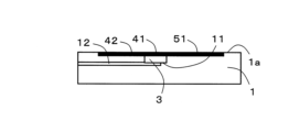
以下、可動部材1の基体の軸受面1aから気体を噴出させる実施形態について、図2A~4に基づいて説明する。図2Aは、本開示の一実施形態に係る静圧気体軸受装置の要部を示す平面図である。図3は、図2Aに記載のX-X線で切断した断面を示す説明図である。図4は、凹部11の底面11aを示す平面図である。図2A~4に示すように、可動部材1の基体の軸受面1aには、凹部11と、凹部11の底面11aの一部に開口部12aを有する気体供給孔12とが位置している。
Below, an embodiment in which gas is ejected from the bearing surface 1a of the base of the movable member 1 will be described with reference to Figures 2A to 4. Figure 2A is a plan view showing the main parts of a hydrostatic gas bearing device according to one embodiment of the present disclosure. Figure 3 is an explanatory diagram showing a cross section taken along line X-X in Figure 2A. Figure 4 is a plan view showing the bottom surface 11a of the recess 11. As shown in Figures 2A to 4, the bearing surface 1a of the base of the movable member 1 is provided with the recess 11 and a gas supply hole 12 having an opening 12a in part of the bottom surface 11a of the recess 11.
凹部11には、多孔質体3が位置している。凹部11の深さは限定されず、例えば1mm以上10mm以下である。多孔質体3は、気体の噴出部となる部材である。多孔質体3は、可動部材1の基体の軸受面1aから突出しないように、凹部11に固定されている。
The porous body 3 is located in the recess 11. The depth of the recess 11 is not limited, and is, for example, 1 mm or more and 10 mm or less. The porous body 3 is a member that serves as the gas ejection portion. The porous body 3 is fixed to the recess 11 so as not to protrude from the bearing surface 1a of the base of the movable member 1.
凹部11の底面11aには、図3および4に示すように、可動部材1の外部と連通している気体供給孔12が接続されている。気体供給孔12は、図4に示すように、凹部11の底面11aの一部に開口部12aを有している。可動部材1の外部から気体供給孔12を通って、噴出部となる多孔質体3に気体が供給される。気体供給孔12は、例えば、基体の側面から形成された横穴でもよく、基体の底面から形成された縦穴でもよく、基体の側面から形成された横穴と、該横穴と底面11aとを接続する縦穴との組合せであってもよい。
As shown in Figures 3 and 4, a gas supply hole 12 that communicates with the outside of the movable member 1 is connected to the bottom surface 11a of the recess 11. As shown in Figure 4, the gas supply hole 12 has an opening 12a in part of the bottom surface 11a of the recess 11. Gas is supplied from the outside of the movable member 1 through the gas supply hole 12 to the porous body 3 that serves as the ejection part. The gas supply hole 12 may be, for example, a horizontal hole formed from the side surface of the base, a vertical hole formed from the bottom surface of the base, or a combination of a horizontal hole formed from the side surface of the base and a vertical hole connecting the horizontal hole and the bottom surface 11a.
多孔質体3は、例えばセラミックスで形成されている。このようなセラミックスとしては、例えば、アルミナ、ジルコニア、炭化珪素、窒化珪素または窒化アルミニウムなどを主成分とするセラミックスが挙げられる。多孔質体3は、凹部11が位置している部材(一実施形態においては、可動部材1)と同じ材料で形成されていてもよい。多孔質体3は、凹部11が位置している部材と同じ材料で形成されている場合、熱膨張率の差が生じにくく温度変化時にも応力が生じにくい。そのため、変形などによって乱流が発生しにくくなり、乱流による微振動がより低減される。多孔質体3の気孔率は限定されず、例えば20%以上50%以下であってもよい。多孔質体3の平均粒子径は限定されず、例えば10μm以上100μm以下であってもよい。
The porous body 3 is made of, for example, ceramics. Examples of such ceramics include ceramics mainly composed of alumina, zirconia, silicon carbide, silicon nitride, or aluminum nitride. The porous body 3 may be made of the same material as the member in which the recess 11 is located (in one embodiment, the movable member 1). When the porous body 3 is made of the same material as the member in which the recess 11 is located, differences in thermal expansion coefficients are unlikely to occur and stress is unlikely to occur even when the temperature changes. Therefore, turbulence is unlikely to occur due to deformation, etc., and micro-vibrations due to turbulence are further reduced. The porosity of the porous body 3 is not limited and may be, for example, 20% to 50%. The average particle size of the porous body 3 is not limited and may be, for example, 10 μm to 100 μm.
多孔質体3の気孔率は、例えば水銀圧入法で求められる。水銀圧入法とは、水銀圧入型ポロシメータを用いて、多孔質体3(試料)の気孔に水銀を圧入(水銀圧入法)し、気孔率を求める方法であり、JIS R 1655-2003に準拠して求めればよい。
The porosity of the porous body 3 can be determined, for example, by mercury intrusion porosimetry. Mercury intrusion porosimetry is a method in which mercury is injected (mercury intrusion porosimetry) into the pores of the porous body 3 (sample) using a mercury intrusion porosimeter to determine the porosity, and can be determined in accordance with JIS R 1655-2003.
多孔質体3の厚みは、凹部11から突出しない範囲であれば限定されない。例えば、多孔質体3の上面と基体の軸受面(一実施形態では、可動部材1の基体の軸受面1a)とが面一であってもよい。多孔質体3の上面と基体の軸受面とが面一である場合、多孔質体3の上面と基体の軸受面との段差による乱流が発生しにくくなる。その結果、乱流による微振動がより低減される。
The thickness of the porous body 3 is not limited as long as it does not protrude from the recess 11. For example, the upper surface of the porous body 3 and the bearing surface of the base (in one embodiment, the bearing surface 1a of the base of the movable member 1) may be flush. When the upper surface of the porous body 3 and the bearing surface of the base are flush, turbulence due to the step between the upper surface of the porous body 3 and the bearing surface of the base is less likely to occur. As a result, micro-vibrations caused by turbulence are further reduced.
多孔質体3の少なくとも底面が、凹部11の底面11aに接着されていてもよい。多孔質体3の少なくとも底面が、凹部11の底面11aに接着されていると、多孔質体3の固定強度を高めることができる。接着方法は限定されず、例えば、アラルダイト(登録商標、ハンツマン・ジャパン社製)およびトールシール(アジレント社製)などのエポキシ系接着剤を用いて接着される。さらに、多孔質体3は、気体供給孔12の開口部12a以外の凹部11の全面に接着されていてもよい。多孔質体3が、気体供給孔12の開口部12a以外の凹部11の全面に接着されていると、気体供給孔12から後述する第1溝41に気体がより流れやすくなる。その結果、気体が多孔質体3全体に分散しやすくなり、微振動がより低減される。
At least the bottom surface of the porous body 3 may be bonded to the bottom surface 11a of the recess 11. When at least the bottom surface of the porous body 3 is bonded to the bottom surface 11a of the recess 11, the fixing strength of the porous body 3 can be increased. The bonding method is not limited, and for example, the porous body 3 may be bonded using an epoxy adhesive such as Araldite (registered trademark, manufactured by Huntsman Japan) and Thor Seal (manufactured by Agilent). Furthermore, the porous body 3 may be bonded to the entire surface of the recess 11 other than the opening 12a of the gas supply hole 12. When the porous body 3 is bonded to the entire surface of the recess 11 other than the opening 12a of the gas supply hole 12, the gas flows more easily from the gas supply hole 12 to the first groove 41 described later. As a result, the gas is more easily dispersed throughout the porous body 3, and micro-vibrations are further reduced.
多孔質体3の表面には、放射線状を有する複数の第1溝41が設けられている。平面視した場合、第1溝41は、図2Aに示すように、多孔質体3の中心領域から外側に向かって形成されている。第1溝41は、多孔質体3の表面の中心領域から多孔質体3の外周に到るように少なくとも1つ形成されていれば限定されない。面内の圧力分布を均一化する観点から、第1溝41は3本以上8本以下でもよい。第1溝41の幅および深さは限定されない。幅は、例えば0.5mm以上2mm以下であってもよい。深さは、例えば0.005mm以上0.05mm以下であってもよい。
The surface of the porous body 3 is provided with a plurality of radial first grooves 41. When viewed in a plane, the first grooves 41 are formed from the central region of the porous body 3 toward the outside, as shown in FIG. 2A. There are no limitations on the number of first grooves 41, as long as at least one is formed from the central region of the surface of the porous body 3 to the outer periphery of the porous body 3. From the viewpoint of uniforming the pressure distribution within the surface, the number of first grooves 41 may be three or more and eight or less. The width and depth of the first grooves 41 are not limited. The width may be, for example, 0.5 mm or more and 2 mm or less. The depth may be, for example, 0.005 mm or more and 0.05 mm or less.
第1溝41の長さ方向に垂直な断面形状は、特に限定されない。この断面形状は、例えば、溝の開口部と底部とが同じ幅であるコの字状、あるいは溝の開口部の幅が底部の幅よりも大きいV字状、またはU字状(底部に曲線を有する形状)などでもよい。特に、気体の乱流を低減するという観点からは、溝の開口部の幅が底部の幅よりも大きいV字状またはU字状であってもよい。溝の断面積が同じで、幅と深さが異なる溝を比較すると、溝の表面積は溝が縦長の(幅が深さよりも小さい)場合に大きくなる。そのため、抵抗による損失が大きくなりやすいので、溝の幅は深さより大きい方がよい。ただし、幅に対し深さが大きくなりすぎると微振動が増加しやすい。そのため、幅は深さの100倍以下であるとよい。
The cross-sectional shape perpendicular to the length direction of the first groove 41 is not particularly limited. This cross-sectional shape may be, for example, a U-shape in which the opening and bottom of the groove are the same width, or a V-shape in which the opening width of the groove is larger than the bottom width, or a U-shape (shape with a curved bottom). In particular, from the viewpoint of reducing gas turbulence, the groove may be a V-shape or a U-shape in which the opening width of the groove is larger than the bottom width. When comparing grooves with the same cross-sectional area but different widths and depths, the surface area of the groove is larger when the groove is elongated (the width is smaller than the depth). Therefore, since losses due to resistance are likely to be large, it is better for the width of the groove to be larger than the depth. However, if the depth is too large compared to the width, micro-vibrations are likely to increase. Therefore, the width should be 100 times or less than the depth.
複数の第1溝41において隣接する2本の第1溝41によって形成される角は、同じ角度を有していてもよい。このような構成を有することによって、第1溝41を流れる気体がより均等になる。その結果、気体の流れのばらつきが低減される。図2Aでは、4本の第1溝41が、90°の間隔を空けて形成されている。
The angles formed by two adjacent first grooves 41 in a plurality of first grooves 41 may have the same angle. With such a configuration, the gas flowing through the first grooves 41 becomes more uniform. As a result, the variation in the gas flow is reduced. In FIG. 2A, four first grooves 41 are formed at intervals of 90°.
基体の軸受面(一実施形態では、可動部材1の基体の軸受面1a)には、第1溝41と連通する複数の第2溝42が設けられている。
The bearing surface of the base (in one embodiment, the bearing surface 1a of the base of the movable member 1) is provided with a plurality of second grooves 42 that communicate with the first grooves 41.
第2溝42は、第1溝41と連通しているため、図2Aに示すように、第1溝41と一直線上となるように位置している。第2溝42の幅および深さは、例えば、第1溝41の幅および深さと同じである。
The second groove 42 is connected to the first groove 41, and is therefore positioned in a straight line with the first groove 41, as shown in FIG. 2A. The width and depth of the second groove 42 are, for example, the same as the width and depth of the first groove 41.
一実施形態に係る静圧気体軸受装置は、第1溝41、第2溝42を有する。そのため、多孔質体3から噴出する気体を、第1溝41によって第2溝42に移動させることができる。その結果、気体を可動部材1の基体に移動させることができる。したがって、可動部材1の基体で浮遊力を発生させることができ、浮遊力が安定して微振動が低減する。
The hydrostatic gas bearing device according to one embodiment has a first groove 41 and a second groove 42. Therefore, the gas ejected from the porous body 3 can be moved to the second groove 42 by the first groove 41. As a result, the gas can be moved to the base of the movable member 1. Therefore, a buoyancy force can be generated in the base of the movable member 1, and the buoyancy force is stabilized, reducing micro-vibrations.
基体の軸受面1aには、第2溝42と交差する第1交差溝51が設けられていてもよい。このような構成によって、第2溝42を流れる気体を第2溝42と交差する方向にも分散でき、微振動がより低減される。「交差」としては、二差、三差および四差などが挙げられる。二差は、交点から2方向に向かう構造を意味し、例えば、L字型などが挙げられる。三差は、交点から3方向に向かう構造を意味し、例えば、T字型およびY字型などが挙げられる。四差は、交点から4方向に向かう構造を意味し、例えば、十字型、X字型および卍型などが挙げられる。
The bearing surface 1a of the base may be provided with a first intersecting groove 51 that intersects with the second groove 42. With this configuration, the gas flowing through the second groove 42 can be dispersed in a direction that intersects with the second groove 42, further reducing micro-vibrations. Examples of "intersecting" include two-crossing, three-crossing, and four-crossing. Two-crossing means a structure that faces in two directions from an intersection, such as an L-shape. Three-crossing means a structure that faces in three directions from an intersection, such as a T-shape and a Y-shape. Four-crossing means a structure that faces in four directions from an intersection, such as a cross shape, an X-shape, and a swastika shape.
第1交差溝51は、第2溝42の終端で接続されていてもよく、第2溝42の途中で接続されていてもよい。第1交差溝51は、その終端が第2溝42に接続されていてもよく、第1交差溝51の途中が第2溝45に接続されていてもよい。
The first intersecting groove 51 may be connected at the end of the second groove 42, or may be connected midway through the second groove 42. The first intersecting groove 51 may be connected at its end to the second groove 42, or may be connected midway through the first intersecting groove 51 to the second groove 45.
第1交差溝51は、隣接する第2溝45同士を接続していてもよい。これにより、軸受面1aに均一に気体が供給されやすい。図2Aでは、第1交差溝51は、第2溝42の終端同士を接続するように位置している。図2Aでは、第1交差溝51は、平面視した場合に、長方形状の軸受面1aに合わせて長方形状に形成されている。このように、第1交差溝51は、軸受面1aの外形状に平行に形成するのが好ましい。しかし、第2溝42同士を接続するように形成されていれば、第1交差溝51の形状は限定されない。
The first intersecting groove 51 may connect adjacent second grooves 45. This makes it easier to supply gas uniformly to the bearing surface 1a. In FIG. 2A, the first intersecting groove 51 is positioned so as to connect the ends of the second grooves 42. In FIG. 2A, the first intersecting groove 51 is formed in a rectangular shape to match the rectangular bearing surface 1a when viewed in a plan view. In this way, it is preferable to form the first intersecting groove 51 parallel to the outer shape of the bearing surface 1a. However, the shape of the first intersecting groove 51 is not limited as long as it is formed so as to connect the second grooves 42.
例えば、第1交差溝51は、図2Aに示すように、第2溝42同士を接続するように環状に形成されていてもよい。第1交差溝51は基体の軸受面1aと相似形(図2Aのような長方形の軸受面1aであれば長方形の第1交差溝51)であってもよい。これにより、軸受面1aに均一に気体が供給されやすい。第1交差溝51の幅および深さは、例えば、第1溝41の幅および深さと同じである。
For example, the first intersecting groove 51 may be formed in a ring shape so as to connect the second grooves 42 together, as shown in FIG. 2A. The first intersecting groove 51 may be similar in shape to the bearing surface 1a of the base (if the bearing surface 1a is rectangular as shown in FIG. 2A, the first intersecting groove 51 may be rectangular). This makes it easier for gas to be supplied uniformly to the bearing surface 1a. The width and depth of the first intersecting groove 51 are, for example, the same as the width and depth of the first groove 41.
図2Aでは、第1交差溝51は、第2溝42の終端同士を接続するように環状に形成されている。しかし、第1交差溝51は、図2Bに示すように、第2溝42の終端以外の部分を接続するように環状に形成されていてもよい。図2Bは、本開示の一実施形態に係る静圧気体軸受装置の要部の変形例を示す平面図である。
In FIG. 2A, the first intersecting groove 51 is formed in an annular shape so as to connect the ends of the second grooves 42. However, as shown in FIG. 2B, the first intersecting groove 51 may be formed in an annular shape so as to connect portions other than the ends of the second grooves 42. FIG. 2B is a plan view showing a modified example of a main part of a hydrostatic gas bearing device according to an embodiment of the present disclosure.
さらに、第1交差溝51は、図2Cに示すように、部分的に環状構造を有していてもよい(本開示では、このような部分的環状構造も環状とする)。図2Cは、本開示の一実施形態に係る静圧気体軸受装置の要部の他の変形例を示す平面図である。
Furthermore, the first intersecting groove 51 may have a partially annular structure as shown in FIG. 2C (in this disclosure, such a partially annular structure is also considered to be annular). FIG. 2C is a plan view showing another modified example of the main part of the hydrostatic gas bearing device according to one embodiment of the present disclosure.
図5に示すように、多孔質体3には、第1溝41と交差接続する少なくとも1つの第2交差溝52が、さらに設けられていてもよい。図5は、本開示の他の実施形態に係る静圧気体軸受装置の要部を示す平面図である。第2交差溝52が設けられることによって、気体の流れのばらつきが低減される。第2交差溝52は、複数の第1溝41間を接続していてもよい。これにより、多孔質体3の表面に均一に気体が供給されやすい。
As shown in FIG. 5, the porous body 3 may further be provided with at least one second intersecting groove 52 that intersects and connects with the first groove 41. FIG. 5 is a plan view showing a main portion of a hydrostatic gas bearing device according to another embodiment of the present disclosure. By providing the second intersecting groove 52, the variation in the gas flow is reduced. The second intersecting groove 52 may connect between a plurality of first grooves 41. This makes it easier for gas to be supplied uniformly to the surface of the porous body 3.
第2交差溝52は、平面視した場合に、多孔質体3と相似形であってもよい。図5では、平面視した場合、多孔質体3は円形状を有しており、第2交差溝52も円形状(円環状)を有している。図5において第2交差溝52は、円形状(円環状)を有している。しかし、第2交差溝52は、第1溝41間を接続し得る形状であれば、環状に限定されない。
The second intersecting groove 52 may have a similar shape to the porous body 3 when viewed in a plan view. In FIG. 5, the porous body 3 has a circular shape when viewed in a plan view, and the second intersecting groove 52 also has a circular shape (annular shape). In FIG. 5, the second intersecting groove 52 has a circular shape (annular shape). However, the second intersecting groove 52 is not limited to annular shape as long as it has a shape that can connect the first grooves 41.
基体の軸受面(可動部材1の基体の軸受面1a)、多孔質体3の表面および各溝の内壁面の算術平均粗さRaは限定されない。例えば、基体の軸受面の算術平均粗さRaは、第2溝42の内壁面の算術平均粗さRaよりも小さくてもよい。基体の軸受面の算術平均粗さRaが、第2溝42の内壁面の算術平均粗さRaよりも小さい場合、第2溝42の内壁面は比較的粗く、流れる気体の速度を遅くすることができる。その結果、振動が吸収されて微振動が低減する。一方、基体の軸受面は比較的滑らかである。そのため、気体が軸受面(軸受面1a)に均一に広がりやすく、可動部材1をスムーズに移動させることができる。
The arithmetic mean roughness Ra of the bearing surface of the base (bearing surface 1a of the base of the movable member 1), the surface of the porous body 3, and the inner wall surface of each groove is not limited. For example, the arithmetic mean roughness Ra of the bearing surface of the base may be smaller than the arithmetic mean roughness Ra of the inner wall surface of the second groove 42. If the arithmetic mean roughness Ra of the bearing surface of the base is smaller than the arithmetic mean roughness Ra of the inner wall surface of the second groove 42, the inner wall surface of the second groove 42 is relatively rough and can slow down the speed of the flowing gas. As a result, vibrations are absorbed and micro-vibrations are reduced. On the other hand, the bearing surface of the base is relatively smooth. Therefore, the gas can easily spread evenly over the bearing surface (bearing surface 1a), allowing the movable member 1 to move smoothly.
さらに、多孔質体3の表面の算術平均粗さRaは、第1溝41の内壁面の算術平均粗さRaよりも小さくてもよい。多孔質体3の表面の算術平均粗さRaが、第1溝41の内壁面の算術平均粗さRaよりも小さい場合、第1溝41の内壁面は比較的粗く、流れる気体の速度を遅くすることができる。その結果、振動が吸収されて微振動が低減する。一方、多孔質体3の表面は比較的滑らかである。そのため、気体が多孔質体3の表面に均一に広がりやすく、可動部材1をスムーズに移動させることができる。
Furthermore, the arithmetic mean roughness Ra of the surface of the porous body 3 may be smaller than the arithmetic mean roughness Ra of the inner wall surface of the first groove 41. When the arithmetic mean roughness Ra of the surface of the porous body 3 is smaller than the arithmetic mean roughness Ra of the inner wall surface of the first groove 41, the inner wall surface of the first groove 41 is relatively rough and can slow down the speed of the flowing gas. As a result, vibrations are absorbed and micro-vibrations are reduced. On the other hand, the surface of the porous body 3 is relatively smooth. Therefore, the gas can easily spread evenly over the surface of the porous body 3, allowing the movable member 1 to move smoothly.
基体の軸受面の算術平均粗さRaは、例えば0.1μm以上1.0μm以下であってもよい。多孔質体3の表面の算術平均粗さRaは、例えば0.1μm以上2.0μm以下であってもよい。第1溝41の内壁面の算術平均粗さRaは、例えば0.5μm以上3.0μm以下であってもよい。第2溝42の内壁面の算術平均粗さRaは、例えば1.0μm以上4.0μm以下であってもよい。
The arithmetic mean roughness Ra of the bearing surface of the base may be, for example, 0.1 μm or more and 1.0 μm or less. The arithmetic mean roughness Ra of the surface of the porous body 3 may be, for example, 0.1 μm or more and 2.0 μm or less. The arithmetic mean roughness Ra of the inner wall surface of the first groove 41 may be, for example, 0.5 μm or more and 3.0 μm or less. The arithmetic mean roughness Ra of the inner wall surface of the second groove 42 may be, for example, 1.0 μm or more and 4.0 μm or less.
基体の軸受面、多孔質体3の表面および各溝の内壁面の算術平均粗さRaは、JIS B 0601:2001に準拠し、形状解析レーザ顕微鏡((株)キーエンス製、VK-X1100またはその後継機種)を用いて測定することができる。測定条件としては、測定倍率を240倍、カットオフ値λsを無し、カットオフ値λcを0.08mmおよびカットオフ値fsを無しとする。測定対象とする面1か所の測定範囲を1420μm×1070μmとして、測定対象とする面から測定範囲をそれぞれ4か所設定すればよい。各測定範囲に、測定対象とする線を略等間隔に4本引いて、表面粗さ計測を行えばよい。計測の対象とする線1本当たりの長さは、1320μmである。
The arithmetic mean roughness Ra of the bearing surface of the base, the surface of the porous body 3, and the inner wall surface of each groove can be measured in accordance with JIS B 0601:2001 using a shape analysis laser microscope (Keyence Corporation, VK-X1100 or its successor model). Measurement conditions are a measurement magnification of 240x, no cutoff value λs, a cutoff value λc of 0.08mm, and no cutoff value fs. The measurement range on one surface to be measured is 1420μm×1070μm, and four measurement ranges are set on each surface to be measured. Four lines to be measured are drawn at approximately equal intervals in each measurement range, and surface roughness measurements are performed. The length of each line to be measured is 1320μm.
第1溝41の断面積は、第2溝42の断面積と同じか、第2溝42の断面積より大きくてもよい。多孔質体3は、微細穴による絞り効果(流体を細い穴に通すことで分子が圧縮される)で圧力が高くなって通気抵抗が大きくなる傾向がある。よって、上記のような多孔質体3の表面に溝を有する構成により、第1溝41の通気抵抗を小さくすることができ、第2溝42に気体をスムーズに供給できる。第1溝41の断面積および第2溝42の断面積は、各溝の深さおよび幅の少なくとも一方を変えることで所望の断面積とすることができる。
The cross-sectional area of the first groove 41 may be the same as or larger than the cross-sectional area of the second groove 42. The porous body 3 tends to have high pressure and high airflow resistance due to the squeezing effect of the fine holes (molecules are compressed by passing a fluid through fine holes). Therefore, by having grooves on the surface of the porous body 3 as described above, the airflow resistance of the first groove 41 can be reduced and gas can be smoothly supplied to the second groove 42. The cross-sectional areas of the first groove 41 and the second groove 42 can be set to the desired cross-sectional area by changing at least one of the depth and width of each groove.
第1溝41の断面積とは、第1溝41を、その延伸方向に対して垂直に切断した断面において、多孔質体3の表面を通る仮想平面と第1溝41の内壁とで囲まれる領域の面積を意味する。第2溝42の断面積とは、第2溝42を、その延伸方向に対して垂直に切断した断面において、基体の軸受面を通る仮想平面と第2溝42の内壁とで囲まれる領域の面積を意味する。
The cross-sectional area of the first groove 41 means the area of the region surrounded by an imaginary plane passing through the surface of the porous body 3 and the inner wall of the first groove 41 in a cross section of the first groove 41 cut perpendicular to its extension direction. The cross-sectional area of the second groove 42 means the area of the region surrounded by an imaginary plane passing through the bearing surface of the base and the inner wall of the second groove 42 in a cross section of the second groove 42 cut perpendicular to its extension direction.
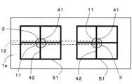
図6に示すように、基体の軸受面(可動部材1の基体の軸受面1a)に複数の凹部11が位置し、複数の多孔質体3が複数の凹部11それぞれに固定されていてもよい。図6は、本開示のさらに他の実施形態に係る静圧気体軸受装置の要部を示す平面図である。複数の多孔質体3が複数の凹部11それぞれに固定されることによって、軸受面内の気体噴出が均一になる。その結果、このように固定される構造は、例えば、より大面積の軸受面に適用できる。
As shown in FIG. 6, a plurality of recesses 11 may be located on the bearing surface of the base (bearing surface 1a of the base of the movable member 1), and a plurality of porous bodies 3 may be fixed to each of the plurality of recesses 11. FIG. 6 is a plan view showing a main portion of a hydrostatic gas bearing device according to yet another embodiment of the present disclosure. By fixing a plurality of porous bodies 3 to each of the plurality of recesses 11, the gas ejection within the bearing surface becomes uniform. As a result, a structure in which the bodies are fixed in this manner can be applied, for example, to a bearing surface having a larger area.
複数の多孔質体3が複数の凹部11それぞれに固定される実施形態では、図6に示すように、1つの多孔質体3、多孔質体3に設けられた第1溝41、第1溝41と連通する第2溝42、および第2溝42と交差する第1交差溝51を1つのユニットとした場合、ユニットは軸受面1aに複数位置しており、各ユニット同士が接触しないように、各ユニットが独立して位置していてもよい。
In an embodiment in which multiple porous bodies 3 are fixed to multiple recesses 11, as shown in FIG. 6, if one porous body 3, a first groove 41 provided in the porous body 3, a second groove 42 communicating with the first groove 41, and a first intersecting groove 51 intersecting with the second groove 42 are considered as one unit, the units are located in multiple positions on the bearing surface 1a, and each unit may be located independently so that they do not come into contact with each other.
各ユニットが独立して位置している場合、図7に示すように、隣接するユニット同士が、連通溝53を介して接続されていてもよい。図7は、本開示のさらに他の実施形態に係る静圧気体軸受装置の要部を示す平面図である。隣接するユニット同士が、連通溝53を介して接続されていると、各ユニットにおける気体の流れのばらつきが低減される。その結果、気体が軸受面(軸受面1a)に均一に広がりやすくなる。
When each unit is positioned independently, adjacent units may be connected via a communication groove 53, as shown in FIG. 7. FIG. 7 is a plan view showing a main portion of a hydrostatic gas bearing device according to yet another embodiment of the present disclosure. When adjacent units are connected via a communication groove 53, the variation in the gas flow in each unit is reduced. As a result, the gas tends to spread evenly across the bearing surface (bearing surface 1a).
さらに、図8に示すように、隣接するユニットは、一方のユニットの一部である第1交差溝51の一部と、他方のユニットの一部である第1交差溝51の一部とが共有溝54によって共有されることによって、隣接するユニット同士が接続されていてもよい。言い換えれば、隣接するユニットのうち、一方のユニットの第1交差溝51の一部が共有溝54を含み、他方のユニットの第1交差溝51の一部もこの共有溝54を含んでいてもよい。これにより、隣接する多孔質体3同士の気体の流れのばらつきが低減される。その結果、気体が軸受面(軸受面1a)に均一に広がりやすくなる。
Furthermore, as shown in FIG. 8, adjacent units may be connected to each other by sharing a shared groove 54 between a part of the first intersecting groove 51 that is part of one unit and a part of the first intersecting groove 51 that is part of the other unit. In other words, a part of the first intersecting groove 51 of one of the adjacent units may include a shared groove 54, and a part of the first intersecting groove 51 of the other unit may also include this shared groove 54. This reduces the variation in the gas flow between adjacent porous bodies 3. As a result, the gas is more likely to spread evenly over the bearing surface (bearing surface 1a).
多孔質体3の表面に第1溝41および第2交差溝52を形成する方法、ならびに基体の軸受面(可動部材1の基体の軸受面1a)に第2溝42、第1交差溝51および連通溝53を形成する方法について、溝が形成される方法であれば限定されない。
The method for forming the first groove 41 and the second intersecting groove 52 on the surface of the porous body 3, and the method for forming the second groove 42, the first intersecting groove 51 and the communicating groove 53 on the bearing surface of the base (bearing surface 1a of the base of the movable member 1) are not limited as long as they are methods that form grooves.
例えば、多孔質体3および可動部材1の基体(または固定部材2の基体)を作製した後、研削または研磨などによって各溝が形成されてもよく、多孔質体3および基体を作製する際に、予め各溝が形成されるようにしてもよい。各溝を予め形成する方法としては、多孔質体3および基体がセラミックスで形成されている場合、各溝となる部分が形成された前駆体(成型体)を得、この前駆体を焼成すればよい。あるいは、基体の凹部11に多孔質体3が固定された後、各溝が形成されてもよい。この場合、第1溝41および第1溝41と連通する第2溝42が一体的に形成される。そのため、第1溝41と第2溝42との位置精度が向上する。
For example, after the porous body 3 and the base of the movable member 1 (or the base of the fixed member 2) are produced, the grooves may be formed by grinding or polishing, or the grooves may be formed in advance when the porous body 3 and the base are produced. When the porous body 3 and the base are made of ceramics, a method for forming the grooves in advance is to obtain a precursor (molded body) in which the portions that will become the grooves are formed, and then sinter this precursor. Alternatively, the porous body 3 may be fixed to the recess 11 of the base, and then the grooves may be formed. In this case, the first groove 41 and the second groove 42 that communicates with the first groove 41 are integrally formed. This improves the positional accuracy of the first groove 41 and the second groove 42.
本開示に係る静圧気体軸受装置は、上述の実施形態に係る静圧気体軸受装置に限定されない。上述の実施形態に係る静圧気体軸受装置では、第2溝42の終端同士を接続する第1交差溝51が設けられている。しかし、本開示に係る静圧気体軸受装置において、第1交差溝以外に、第1交差溝と多孔質体との間に、さらに交差溝が設けられていてもよい。このさらなる交差溝は、少なくとも1周設けられていればよく、第1交差溝と同心環状に設けられていてもよい。
The hydrostatic gas bearing device according to the present disclosure is not limited to the hydrostatic gas bearing device according to the above-mentioned embodiment. In the hydrostatic gas bearing device according to the above-mentioned embodiment, a first intersecting groove 51 is provided that connects the ends of the second grooves 42. However, in the hydrostatic gas bearing device according to the present disclosure, in addition to the first intersecting groove, a further intersecting groove may be provided between the first intersecting groove and the porous body. This further intersecting groove only needs to be provided around at least one circumference, and may be provided in a concentric ring shape with the first intersecting groove.
上述の他の実施形態に係る静圧気体軸受装置では、1つの多孔質体3、多孔質体3に設けられた第1溝41、第1溝41と連通する第2溝42、および第2溝42の終端同士を接続する第1交差溝51を含むユニットが、2つ示されている。しかし、このユニットは3つ以上存在していてもよい。このユニットは、直線状に位置していてもよく、縦および横に格子状に位置していてもよく、ランダムに位置していてもよい。
In the hydrostatic gas bearing device according to the other embodiment described above, two units are shown, each unit including one porous body 3, a first groove 41 provided in the porous body 3, a second groove 42 communicating with the first groove 41, and a first intersecting groove 51 connecting the ends of the second groove 42. However, there may be three or more units. The units may be positioned in a straight line, in a vertical and horizontal grid pattern, or randomly.
図9Aは、本開示のさらに他の実施形態に係る静圧気体軸受装置の要部を示す平面図である。図2Aの静圧気体軸受装置において、第1交差溝51の途中に、他の多孔質体3aおよび他の多孔質体3a上に位置する他の第1溝41aが位置していてもよい。このような場合でも、第1交差溝51で隣接する第2溝42同士を接続していると言える。
FIG. 9A is a plan view showing a main portion of a hydrostatic gas bearing device according to yet another embodiment of the present disclosure. In the hydrostatic gas bearing device of FIG. 2A, another porous body 3a and another first groove 41a located on the other porous body 3a may be located in the middle of the first intersecting groove 51. Even in such a case, it can be said that the first intersecting groove 51 connects adjacent second grooves 42.
図9Bは、本開示のさらに他の実施形態に係る静圧気体軸受装置の要部を示す平面図である。図2Aの静圧気体軸受装置において、第2溝42と第1交差溝51の接続部に、他の多孔質体3aおよび他の多孔質体3a上に位置する他の第1溝41aが位置していてもよい。このような場合でも、第1交差溝51は第2溝42に交差していると言える。
FIG. 9B is a plan view showing a main portion of a hydrostatic gas bearing device according to yet another embodiment of the present disclosure. In the hydrostatic gas bearing device of FIG. 2A, another porous body 3a and another first groove 41a located on the other porous body 3a may be located at the connection between the second groove 42 and the first intersecting groove 51. Even in such a case, it can be said that the first intersecting groove 51 intersects with the second groove 42.
図9Aおよび図9Bのような構成により、気体が供給される多孔質体の数を増やすことができる。そのため、軸受面に均一に気体を流すことができ、微振動がより低減される。
The configuration shown in Figures 9A and 9B allows the number of porous bodies to which gas is supplied to be increased. This allows the gas to flow evenly over the bearing surface, further reducing micro-vibrations.
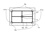
図10は、本開示のさらに他の実施形態に係る静圧気体軸受装置の要部を示す平面図である。図10の静圧気体軸受装置は、多孔質体3と、この多孔質体3上に位置する第1溝41と、第1溝41に連通する第2溝42と、第2溝42に交差する第1交差溝51とを有していると言える。図10では、第2溝42と第1交差溝51の接続部に、他の多孔質体3aおよび多孔質体3a上に位置する他の第1溝41aが位置していていると言える。このような構成でも、可動部材1の浮遊力が安定して微振動が低減する。
FIG. 10 is a plan view showing the main parts of a hydrostatic gas bearing device according to yet another embodiment of the present disclosure. The hydrostatic gas bearing device of FIG. 10 can be said to have a porous body 3, a first groove 41 located on the porous body 3, a second groove 42 communicating with the first groove 41, and a first intersecting groove 51 intersecting the second groove 42. In FIG. 10, another porous body 3a and another first groove 41a located on the porous body 3a can be said to be located at the connection between the second groove 42 and the first intersecting groove 51. Even with this configuration, the buoyancy of the movable member 1 is stabilized and micro-vibrations are reduced.
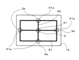
図11Aは、本開示のさらに他の実施形態に係る静圧気体軸受装置の要部を示す平面図である。図11Aの静圧気体軸受装置は、多孔質体3と、この多孔質体3上に位置する第1溝41と、第1溝41に連通する第2溝42と、第2溝42に交差する第1交差溝51とを有している。図11Aに示すように、第1交差溝51は、環状構造を有していなくてもよい。
FIG. 11A is a plan view showing a main portion of a hydrostatic gas bearing device according to yet another embodiment of the present disclosure. The hydrostatic gas bearing device of FIG. 11A has a porous body 3, a first groove 41 located on the porous body 3, a second groove 42 communicating with the first groove 41, and a first intersecting groove 51 intersecting the second groove 42. As shown in FIG. 11A, the first intersecting groove 51 does not have to have an annular structure.
図11Bは、本開示のさらに他の実施形態に係る静圧気体軸受装置の要部を示す平面図である。図11Bは、図11Aの静圧気体軸受装置において第1交差溝51の終端に、他の多孔質体3aおよび他の多孔質体3a上に位置する他の第1溝41aが位置している。このような場合でも、第1交差溝51は第2溝42に交差していると言える。図11Aおよび図11Bのような構成でも可動部材1の浮遊力が安定して微振動が低減する。
FIG. 11B is a plan view showing the main parts of a hydrostatic gas bearing device according to yet another embodiment of the present disclosure. In FIG. 11B, another porous body 3a and another first groove 41a located on the other porous body 3a are located at the end of the first intersecting groove 51 in the hydrostatic gas bearing device of FIG. 11A. Even in such a case, it can be said that the first intersecting groove 51 intersects with the second groove 42. Even with the configurations shown in FIGS. 11A and 11B, the buoyancy of the movable member 1 is stabilized and micro-vibrations are reduced.
以下、実施例および比較例を挙げて本開示に係る静圧気体軸受装置を具体的に説明するが、本開示に係る静圧気体軸受装置は、下記の実施例に限定されるものではない。
Below, the hydrostatic gas bearing device according to the present disclosure will be specifically explained using examples and comparative examples, but the hydrostatic gas bearing device according to the present disclosure is not limited to the examples below.
(実施例1)
まず、図1に示すような静圧気体軸受装置を作製した。実施例1の静圧気体軸受装置に含まれる可動部材1は、アルミナ製であり、純度が99.5質量%のアルミナを用いて作製した。4つの軸受面1aの寸法について、それぞれ幅は100mmであり、移動方向の長さは100mmである。 Example 1
First, an aerostatic bearing device was fabricated as shown in Fig. 1. Themovable member 1 included in the aerostatic bearing device of Example 1 was made of alumina with a purity of 99.5 mass%. The dimensions of the four bearing surfaces 1a were each 100 mm in width and 100 mm in length in the moving direction.
まず、図1に示すような静圧気体軸受装置を作製した。実施例1の静圧気体軸受装置に含まれる可動部材1は、アルミナ製であり、純度が99.5質量%のアルミナを用いて作製した。4つの軸受面1aの寸法について、それぞれ幅は100mmであり、移動方向の長さは100mmである。 Example 1
First, an aerostatic bearing device was fabricated as shown in Fig. 1. The
4つの軸受面1aそれぞれには、図2Aに示すような多孔質体3、第1溝41、第2溝42および第1交差溝51を含むユニットが、1つ含まれている。第2溝42および第1交差溝51は、いずれも1mmの幅および0.02mmの深さを有する。第1交差溝51は、平面視した場合に正方形状の環状構造を有する。第1交差溝51において、可動部材1の移動方向に直交する方向の長さは50mmであり、可動部材1の移動方向の長さは50mmである。
Each of the four bearing surfaces 1a includes one unit including a porous body 3, a first groove 41, a second groove 42, and a first intersecting groove 51 as shown in FIG. 2A. The second groove 42 and the first intersecting groove 51 each have a width of 1 mm and a depth of 0.02 mm. The first intersecting groove 51 has a square ring-shaped structure when viewed in a plan view. The length of the first intersecting groove 51 in the direction perpendicular to the moving direction of the movable member 1 is 50 mm, and the length in the moving direction of the movable member 1 is 50 mm.
多孔質体3はアルミナ製であり、純度が99.5質量%のアルミナを用いて作製し、平均粒子径は80μmであり、気孔率は40%である。多孔質体3は10mmの直径を有している。多孔質体3に位置している第1溝41は、1mmの幅および0.02mmの深さを有する。
The porous body 3 is made of alumina, and is made using alumina with a purity of 99.5% by mass, with an average particle size of 80 μm and a porosity of 40%. The porous body 3 has a diameter of 10 mm. The first groove 41 located in the porous body 3 has a width of 1 mm and a depth of 0.02 mm.
実施例1の静圧気体軸受装置に含まれる固定部材2は、アルミナ製であり、純度が99.5質量%のアルミナを用いて作製した。固定部材2の縦および横の長さは80mmであり、長手方向の長さ(可動部材1が移動する方向の長さ)は300mmである。
The fixed member 2 included in the hydrostatic gas bearing device of Example 1 is made of alumina with a purity of 99.5% by mass. The vertical and horizontal lengths of the fixed member 2 are 80 mm, and the length in the longitudinal direction (the length in the direction in which the movable member 1 moves) is 300 mm.
(比較例1)
実施例1で使用した多孔質体3の代わりに、0.2mmの開孔径を有するオリフィス絞りを使用した以外は、実施例1と同様に静圧気体軸受装置を作製した。 (Comparative Example 1)
An aerostatic bearing device was produced in the same manner as in Example 1, except that an orifice restrictor having an opening diameter of 0.2 mm was used instead of theporous body 3 used in Example 1.
実施例1で使用した多孔質体3の代わりに、0.2mmの開孔径を有するオリフィス絞りを使用した以外は、実施例1と同様に静圧気体軸受装置を作製した。 (Comparative Example 1)
An aerostatic bearing device was produced in the same manner as in Example 1, except that an orifice restrictor having an opening diameter of 0.2 mm was used instead of the
実施例1の静圧気体軸受装置および比較例1の静圧気体軸受装置において、可動部材1の気体供給孔12に4kgf/cm2の圧縮気体をそれぞれ供給し、剛性および微振動について各々測定した。剛性は、荷重搭載時の浮上量変化量を測定した。微振動は、静電容量変位計を用いて移動体の微小変位を測定した。
In the hydrostatic gas bearing device of Example 1 and the hydrostatic gas bearing device of Comparative Example 1, compressed gas of 4 kgf/ cm2 was supplied to the gas supply hole 12 of the movable member 1, and the rigidity and micro-vibration were measured. The rigidity was measured by measuring the amount of change in the floating amount when a load was applied. For the micro-vibration, a capacitance displacement meter was used to measure the micro-displacement of the moving body.
実施例1の静圧気体軸受装置は、比較例1の静圧気体軸受装置と同程度の剛性を有していた。一方、微振動について、実施例1の静圧気体軸受装置は、比較例1の静圧気体軸受装置の約1/10に低減することができた。
The hydrostatic gas bearing device of Example 1 had the same rigidity as the hydrostatic gas bearing device of Comparative Example 1. On the other hand, the hydrostatic gas bearing device of Example 1 was able to reduce micro-vibrations to about 1/10 of those of the hydrostatic gas bearing device of Comparative Example 1.
以上、本開示の実施形態について説明した。しかし、本開示に係る発明は上述の実施形態に限定されるものではなく、下記の(1)に示す本開示の範囲内で種々の変更および改良が可能である。
The above describes the embodiments of the present disclosure. However, the invention of the present disclosure is not limited to the above-described embodiments, and various modifications and improvements are possible within the scope of the present disclosure as shown in (1) below.
(1)本開示に係る静圧気体軸受装置は、可動部材と固定部材とを備える。可動部材または固定部材の基体の軸受面には、凹部が位置し、凹部の底面に気体供給孔の開口部が位置している。凹部には、気体の噴出部となる多孔質体が、軸受面から突出しないように位置している。多孔質体の表面には、表面の中心領域から多孔質体の外周に到る第1溝が位置している。基体の軸受面には、第1溝と連通する第2溝が位置している。
(1) The hydrostatic gas bearing device according to the present disclosure comprises a movable member and a fixed member. A recess is located on the bearing surface of the base of the movable member or the fixed member, and the opening of the gas supply hole is located on the bottom surface of the recess. A porous body that serves as a gas outlet is located in the recess so as not to protrude from the bearing surface. A first groove is located on the surface of the porous body, extending from the central region of the surface to the outer periphery of the porous body. A second groove that communicates with the first groove is located on the bearing surface of the base.
本開示の実施形態に関し、以下の(2)~(16)に示す実施形態をさらに開示する。
The following embodiments (2) to (16) are further disclosed with respect to the embodiments of the present disclosure.
(2)上記(1)に記載の静圧気体軸受装置において、軸受面には、第2溝と交差する第1交差溝が位置している。
(3)上記(1)または(2)に記載の静圧気体軸受装置において、第2溝が少なくとも2つ位置しており、第1交差溝は隣接する第2溝同士を接続している。
(4)上記(1)~(3)のいずれかに記載の静圧気体軸受装置において、第1交差溝は環状である。
(5)上記(1)~(4)のいずれかに記載の静圧気体軸受装置において、多孔質体の表面と基体の軸受面とが面一である。
(6)上記(1)~(5)のいずれかに記載の静圧気体軸受装置において、多孔質体は、凹部が位置している部材と同じ材料である。
(7)上記(1)~(6)のいずれかに記載の静圧気体軸受装置において、多孔質体の少なくとも底面が、凹部に接着されている。
(8)上記(7)に記載の静圧気体軸受装置において、多孔質体は、気体供給孔の開口部以外の凹部の全面に接着されている。
(9)上記(1)~(8)のいずれかに記載の静圧気体軸受装置において、第1溝が少なくとも2つ位置しており、隣接する2本の第1溝によって形成される角は、同じ角度を有する。
(10)上記(1)~(9)のいずれかに記載の静圧気体軸受装置において、多孔質体には、第1溝と交差する第2交差溝をさらに位置している。
(11)上記(1)~(10)のいずれかに記載の静圧気体軸受装置において、軸受面に複数の凹部が位置し、複数の多孔質体が複数の凹部それぞれに位置している。
(12)上記(11)に記載の静圧気体軸受装置において、1つの多孔質体、多孔質体に位置する第1溝、第1溝と連通する第2溝、および第2溝と交差する第1交差溝を1つのユニットとした場合、ユニットは軸受面に複数位置しており、隣接するユニットが第2溝の少なくとも一部または第1交差溝の少なくとも一部を共有して接続している。
(13)上記(11)に記載の静圧気体軸受装置において、1つの多孔質体、多孔質体に位置する第1溝、第1溝と連通する第2溝、および第2溝と交差する第1交差溝を1つのユニットとした場合、ユニットは軸受面に複数位置しており、各ユニット同士が接触しないように、各ユニットが独立している。
(14)上記(13)に記載の静圧気体軸受装置において、少なくとも2つのユニットにおいて、隣接する前記ユニット同士が、連通溝を介して接続されている。
(15)上記(1)~(14)のいずれかに記載の静圧気体軸受装置において、基体の軸受面の算術平均粗さRaは、第2溝の内壁面の算術平均粗さRaよりも小さい。
(16)上記(1)~(15)のいずれかに記載の静圧気体軸受装置において、多孔質体の表面の算術平均粗さRaは、第1溝の内壁面の算術平均粗さRaよりも小さい。 (2) In the hydrostatic bearing device described in (1) above, a first intersecting groove is positioned on the bearing surface so as to intersect with the second groove.
(3) In the hydrostatic bearing device described in (1) or (2) above, at least two second grooves are positioned, and the first intersecting groove connects adjacent second grooves to each other.
(4) In the hydrostatic bearing device according to any one of (1) to (3) above, the first intersecting groove is annular.
(5) In the hydrostatic gas bearing device according to any one of (1) to (4) above, the surface of the porous body and the bearing surface of the base are flush with each other.
(6) In the hydrostatic gas bearing device according to any one of (1) to (5) above, the porous body is made of the same material as the member in which the recess is located.
(7) In the hydrostatic gas bearing device according to any one of (1) to (6) above, at least the bottom surface of the porous body is bonded to the recess.
(8) In the hydrostatic gas bearing device described in (7) above, the porous body is bonded to the entire surface of the recess other than the opening of the gas supply hole.
(9) In the hydrostatic gas bearing device described in any one of (1) to (8) above, at least two first grooves are positioned, and the angles formed by two adjacent first grooves are the same.
(10) In the hydrostatic gas bearing device according to any one of (1) to (9) above, the porous body further includes second intersecting grooves that intersect with the first grooves.
(11) In the hydrostatic gas bearing device according to any one of (1) to (10) above, a plurality of recesses are located on the bearing surface, and a plurality of porous bodies are located in each of the plurality of recesses.
(12) In the hydrostatic gas bearing device described in (11) above, when one porous body, a first groove located in the porous body, a second groove communicating with the first groove, and a first intersecting groove intersecting the second groove are considered to be one unit, a plurality of units are located on the bearing surface, and adjacent units are connected by sharing at least a portion of the second groove or at least a portion of the first intersecting groove.
(13) In the hydrostatic gas bearing device described in (11) above, when one porous body, a first groove located in the porous body, a second groove communicating with the first groove, and a first intersecting groove intersecting the second groove are considered as one unit, a plurality of units are located on the bearing surface, and each unit is independent so as not to come into contact with each other.
(14) In the hydrostatic gas bearing device described above in (13), in at least two of the units, adjacent units are connected via a communication groove.
(15) In the hydrostatic gas bearing device according to any one of (1) to (14) above, the arithmetic mean roughness Ra of the bearing surface of the base is smaller than the arithmetic mean roughness Ra of the inner wall surface of the second groove.
(16) In the hydrostatic gas bearing device according to any one of (1) to (15) above, the arithmetic mean roughness Ra of the surface of the porous body is smaller than the arithmetic mean roughness Ra of the inner wall surface of the first groove.
1 可動部材
1a 可動部材の基体の軸受面
11 凹部
11a 凹部の底面
12 気体供給孔
12a 気体供給孔の開口部
2 固定部材
2a 固定部材の基体の軸受面
3 多孔質体
3a 他の多孔質体
41 第1溝
41a 他の第1溝
42 第2溝
51 第1交差溝
52 第2交差溝
53 連通溝
54 共有溝 REFERENCE SIGNSLIST 1 Movable member 1a Bearing surface of base of movable member 11 Recess 11a Bottom surface of recess 12 Gas supply hole 12a Opening of gas supply hole 2 Fixed member 2a Bearing surface of base of fixed member 3 Porous body 3a Another porous body 41 First groove 41a Another first groove 42 Second groove 51 First intersecting groove 52 Second intersecting groove 53 Communication groove 54 Shared groove
1a 可動部材の基体の軸受面
11 凹部
11a 凹部の底面
12 気体供給孔
12a 気体供給孔の開口部
2 固定部材
2a 固定部材の基体の軸受面
3 多孔質体
3a 他の多孔質体
41 第1溝
41a 他の第1溝
42 第2溝
51 第1交差溝
52 第2交差溝
53 連通溝
54 共有溝 REFERENCE SIGNS
Claims (16)
- 可動部材と固定部材とを備え、
前記可動部材または前記固定部材の基体の軸受面には、凹部が位置し、該凹部の底面には気体供給孔の開口部が位置し、
前記凹部には、気体の噴出部となる多孔質体が、前記軸受面から突出しないように位置し、
前記多孔質体の表面には、該表面の中心領域から前記多孔質体の外周に到る第1溝が位置し、
前記基体の前記軸受面には、前記第1溝と連通する第2溝が位置している
静圧気体軸受装置。 A movable member and a fixed member are provided,
a recess is located on a bearing surface of a base of the movable member or the fixed member, and an opening of a gas supply hole is located on a bottom surface of the recess;
a porous body serving as a gas ejection portion is positioned in the recess so as not to protrude from the bearing surface;
A first groove is located on the surface of the porous body, the first groove extending from a central region of the surface to an outer periphery of the porous body;
A hydrostatic gas bearing device, wherein a second groove communicating with the first groove is positioned in the bearing surface of the base. - 前記軸受面には、前記第2溝と交差する第1交差溝が位置している、請求項1に記載の静圧気体軸受装置。 The hydrostatic gas bearing device according to claim 1, wherein a first intersecting groove that intersects with the second groove is located on the bearing surface.
- 前記第2溝が少なくとも2つ位置しており、前記第1交差溝は隣接する前記第2溝同士を接続している、請求項2に記載の静圧気体軸受装置。 The hydrostatic gas bearing device according to claim 2, wherein at least two of the second grooves are located, and the first intersecting groove connects adjacent second grooves.
- 前記第1交差溝は環状である、請求項1~3のいずれかに記載の静圧気体軸受装置。 The hydrostatic gas bearing device according to any one of claims 1 to 3, wherein the first intersecting groove is annular.
- 前記多孔質体の表面と前記基体の前記軸受面とが面一である、請求項1~4のいずれかに記載の静圧気体軸受装置。 The hydrostatic gas bearing device according to any one of claims 1 to 4, wherein the surface of the porous body and the bearing surface of the base are flush with each other.
- 前記多孔質体は、前記凹部が位置している部材と同じ材料である、請求項1~5のいずれかに記載の静圧気体軸受装置。 The hydrostatic gas bearing device according to any one of claims 1 to 5, wherein the porous body is made of the same material as the member in which the recess is located.
- 前記多孔質体の少なくとも底面が、前記凹部に接着されている、請求項1~6のいずれかに記載の静圧気体軸受装置。 The hydrostatic gas bearing device according to any one of claims 1 to 6, wherein at least the bottom surface of the porous body is bonded to the recess.
- 前記多孔質体は、前記気体供給孔の開口部以外の前記凹部の全面に接着されている、請求項7に記載の静圧気体軸受装置。 The hydrostatic gas bearing device according to claim 7, wherein the porous body is bonded to the entire surface of the recess except for the opening of the gas supply hole.
- 前記第1溝が少なくとも2つ位置しており、隣接する2本の前記第1溝によって形成される角は、同じ角度を有する、請求項1~8のいずれかに記載の静圧気体軸受装置。 The hydrostatic gas bearing device according to any one of claims 1 to 8, wherein at least two of the first grooves are located, and the angles formed by two adjacent first grooves are the same.
- 前記多孔質体には、前記第1溝と交差する第2交差溝がさらに位置している、請求項1~9のいずれかに記載の静圧気体軸受装置。 The hydrostatic gas bearing device according to any one of claims 1 to 9, wherein the porous body further includes a second intersecting groove that intersects with the first groove.
- 前記軸受面に複数の前記凹部が位置し、複数の前記多孔質体が複数の前記凹部それぞれに位置している、請求項1~10のいずれかに記載の静圧気体軸受装置。 The hydrostatic gas bearing device according to any one of claims 1 to 10, wherein a plurality of the recesses are located on the bearing surface, and a plurality of the porous bodies are located in each of the recesses.
- 1つの前記多孔質体、該多孔質体に位置する前記第1溝、該第1溝と連通する前記第2溝および前記第2溝と交差する前記第1交差溝を1つのユニットとした場合、前記ユニットは前記軸受面に複数位置しており、隣接するユニットが各ユニットの少なくとも一部を共有して接続している、請求項11に記載の静圧気体軸受装置。 The hydrostatic gas bearing device according to claim 11, in which, when one of the porous bodies, the first groove located in the porous body, the second groove communicating with the first groove, and the first intersecting groove intersecting with the second groove are considered as one unit, a plurality of the units are located on the bearing surface, and adjacent units are connected by sharing at least a portion of each unit.
- 1つの前記多孔質体、該多孔質体に位置する前記第1溝、該第1溝と連通する前記第2溝、および前記第2溝と交差する前記第1交差溝を1つのユニットとした場合、前記ユニットは前記軸受面に複数位置しており、各ユニット同士が接触しないように、各ユニットが独立している、請求項11に記載の静圧気体軸受装置。 The hydrostatic gas bearing device according to claim 11, in which, when one of the porous bodies, the first groove located in the porous body, the second groove communicating with the first groove, and the first intersecting groove intersecting with the second groove are considered as one unit, a plurality of the units are located on the bearing surface, and each unit is independent so as not to come into contact with each other.
- 少なくとも2つの前記ユニットにおいて、隣接する前記ユニット同士が、連通溝を介して接続されている、請求項13に記載の静圧気体軸受装置。 The hydrostatic gas bearing device according to claim 13, wherein in at least two of the units, adjacent units are connected via a communication groove.
- 前記基体の軸受面の算術平均粗さRaは、前記第2溝の内壁面の算術平均粗さRaよりも小さい、請求項1~14のいずれかに記載の静圧気体軸受装置。 The hydrostatic gas bearing device according to any one of claims 1 to 14, wherein the arithmetic mean roughness Ra of the bearing surface of the base is smaller than the arithmetic mean roughness Ra of the inner wall surface of the second groove.
- 前記多孔質体の表面の算術平均粗さRaは、前記第1溝の内壁面の算術平均粗さRaよりも小さい、請求項1~15のいずれかに記載の静圧気体軸受装置。 The hydrostatic gas bearing device according to any one of claims 1 to 15, wherein the arithmetic mean roughness Ra of the surface of the porous body is smaller than the arithmetic mean roughness Ra of the inner wall surface of the first groove.
Applications Claiming Priority (2)
| Application Number | Priority Date | Filing Date | Title |
|---|---|---|---|
| JP2022-171335 | 2022-10-26 | ||
| JP2022171335 | 2022-10-26 |
Publications (1)
| Publication Number | Publication Date |
|---|---|
| WO2024090442A1 true WO2024090442A1 (en) | 2024-05-02 |
Family
ID=90830837
Family Applications (1)
| Application Number | Title | Priority Date | Filing Date |
|---|---|---|---|
| PCT/JP2023/038377 WO2024090442A1 (en) | 2022-10-26 | 2023-10-24 | Hydrostatic gas bearing device |
Country Status (1)
| Country | Link |
|---|---|
| WO (1) | WO2024090442A1 (en) |
Citations (4)
| Publication number | Priority date | Publication date | Assignee | Title |
|---|---|---|---|---|
| JPH03244827A (en) * | 1990-02-21 | 1991-10-31 | Nippon Seiko Kk | Static pressure gas bearing |
| JP2003232352A (en) * | 2002-02-06 | 2003-08-22 | Nikon Corp | Air pad, stage device using the same and exposure device having stage device |
| JP2011149500A (en) * | 2010-01-22 | 2011-08-04 | Sintokogio Ltd | Hydrostatic bearing device and stage provided with the hydrostatic bearing device |
| CN110848258A (en) * | 2019-12-16 | 2020-02-28 | 江苏集萃精凯高端装备技术有限公司 | Gas static pressure air floating pad and air floating guide rail |
-
2023
- 2023-10-24 WO PCT/JP2023/038377 patent/WO2024090442A1/en unknown
Patent Citations (4)
| Publication number | Priority date | Publication date | Assignee | Title |
|---|---|---|---|---|
| JPH03244827A (en) * | 1990-02-21 | 1991-10-31 | Nippon Seiko Kk | Static pressure gas bearing |
| JP2003232352A (en) * | 2002-02-06 | 2003-08-22 | Nikon Corp | Air pad, stage device using the same and exposure device having stage device |
| JP2011149500A (en) * | 2010-01-22 | 2011-08-04 | Sintokogio Ltd | Hydrostatic bearing device and stage provided with the hydrostatic bearing device |
| CN110848258A (en) * | 2019-12-16 | 2020-02-28 | 江苏集萃精凯高端装备技术有限公司 | Gas static pressure air floating pad and air floating guide rail |
Similar Documents
| Publication | Publication Date | Title |
|---|---|---|
| KR101267442B1 (en) | Static pressure bearing device and stage provided with same | |
| Papautsky et al. | A review of laminar single-phase flow in microchannels | |
| JP5119253B2 (en) | Nozzle member and manufacturing method thereof | |
| US9833780B2 (en) | Microfluidic devices for the generation of nano-vapor bubbles and their methods of manufacture and use | |
| JP6779915B2 (en) | A fluid flow device equipped with a valve unit and its manufacturing method | |
| JP2018526640A (en) | Rheometer with gas bearing | |
| WO2024090442A1 (en) | Hydrostatic gas bearing device | |
| JP5362285B2 (en) | Adsorption roll | |
| US20200266092A1 (en) | Apparatuses and methods for non-contact holding and measurement of thin substrates | |
| JPH09296825A (en) | Static pressure gas bearing | |
| EP1307660A2 (en) | Hydrostatic gas bearing | |
| WO2007077878A1 (en) | Gas pressure control actuator, gas bearing mechanism for the gas pressure control actuator, and minute displacement output device using the gas pressure control actuator | |
| JP3660779B2 (en) | Static pressure gas bearing device | |
| JP5329932B2 (en) | Method for manufacturing silicon fine structure and method for manufacturing fine channel device | |
| JP2007078126A (en) | Non-contact support device | |
| Kim et al. | The fabrication of flow conduits in ceramic tapes and the measurement of fluid flow through these conduits | |
| JP7005810B1 (en) | Gas drawing structure and static pressure gas bearings that make up the static pressure gas bearing | |
| JP5972611B2 (en) | Direct acting levitation device | |
| JP2006029412A (en) | Static pressure type linear motion guide unit | |
| JP4463049B2 (en) | Ceramic structure and positioning device member using the same | |
| JP2022538393A (en) | Microfluidic device and method for manufacturing same | |
| JPS6228519A (en) | Ceramic bearing device | |
| CN112922961B (en) | Static pressure air flotation unit based on porous throttling unit and processing method | |
| JP7061555B2 (en) | Ceramic joint and its manufacturing method | |
| JP2005240825A (en) | Static pressure gas linear motion bearing structure |