WO2024085171A1 - 光吸収フィルタ、光学フィルタ及びその製造方法、有機エレクトロルミネッセンス表示装置、無機エレクトロルミネッセンス表示装置及び液晶表示装置 - Google Patents
光吸収フィルタ、光学フィルタ及びその製造方法、有機エレクトロルミネッセンス表示装置、無機エレクトロルミネッセンス表示装置及び液晶表示装置 Download PDFInfo
- Publication number
- WO2024085171A1 WO2024085171A1 PCT/JP2023/037642 JP2023037642W WO2024085171A1 WO 2024085171 A1 WO2024085171 A1 WO 2024085171A1 JP 2023037642 W JP2023037642 W JP 2023037642W WO 2024085171 A1 WO2024085171 A1 WO 2024085171A1
- Authority
- WO
- WIPO (PCT)
- Prior art keywords
- group
- light
- compound
- dye
- absorbing filter
- Prior art date
Links
- 230000003287 optical effect Effects 0.000 title claims abstract description 90
- 239000004973 liquid crystal related substance Substances 0.000 title claims abstract description 57
- 230000031700 light absorption Effects 0.000 title claims abstract description 36
- 238000004519 manufacturing process Methods 0.000 title claims abstract description 23
- 150000001875 compounds Chemical class 0.000 claims abstract description 187
- 238000010521 absorption reaction Methods 0.000 claims abstract description 102
- 229920005989 resin Polymers 0.000 claims abstract description 95
- 239000011347 resin Substances 0.000 claims abstract description 95
- 230000000295 complement effect Effects 0.000 claims abstract description 11
- 239000000975 dye Substances 0.000 claims description 275
- 229920000642 polymer Polymers 0.000 claims description 74
- 229940126062 Compound A Drugs 0.000 claims description 69
- NLDMNSXOCDLTTB-UHFFFAOYSA-N Heterophylliin A Natural products O1C2COC(=O)C3=CC(O)=C(O)C(O)=C3C3=C(O)C(O)=C(O)C=C3C(=O)OC2C(OC(=O)C=2C=C(O)C(O)=C(O)C=2)C(O)C1OC(=O)C1=CC(O)=C(O)C(O)=C1 NLDMNSXOCDLTTB-UHFFFAOYSA-N 0.000 claims description 69
- 239000002253 acid Substances 0.000 claims description 50
- 238000000034 method Methods 0.000 claims description 33
- 229910052739 hydrogen Inorganic materials 0.000 claims description 16
- 239000001257 hydrogen Substances 0.000 claims description 16
- 238000005401 electroluminescence Methods 0.000 claims description 15
- 230000008859 change Effects 0.000 claims description 14
- 239000000126 substance Substances 0.000 claims description 12
- 230000001678 irradiating effect Effects 0.000 claims description 4
- -1 cinnamylidene Chemical group 0.000 description 191
- 125000001424 substituent group Chemical group 0.000 description 151
- 125000004432 carbon atom Chemical group C* 0.000 description 129
- 239000010410 layer Substances 0.000 description 112
- 125000000217 alkyl group Chemical group 0.000 description 109
- 125000003118 aryl group Chemical group 0.000 description 96
- 239000010408 film Substances 0.000 description 96
- 125000003178 carboxy group Chemical group [H]OC(*)=O 0.000 description 73
- 150000003254 radicals Chemical class 0.000 description 71
- 125000000623 heterocyclic group Chemical group 0.000 description 61
- 125000004435 hydrogen atom Chemical group [H]* 0.000 description 61
- 230000004888 barrier function Effects 0.000 description 59
- 125000003545 alkoxy group Chemical group 0.000 description 58
- 239000007789 gas Substances 0.000 description 58
- 238000002835 absorbance Methods 0.000 description 57
- 238000004042 decolorization Methods 0.000 description 43
- 239000000987 azo dye Substances 0.000 description 42
- 125000001931 aliphatic group Chemical group 0.000 description 40
- 125000002015 acyclic group Chemical group 0.000 description 39
- 239000000758 substrate Substances 0.000 description 36
- NIXOWILDQLNWCW-UHFFFAOYSA-M Acrylate Chemical compound [O-]C(=O)C=C NIXOWILDQLNWCW-UHFFFAOYSA-M 0.000 description 33
- 150000002430 hydrocarbons Chemical group 0.000 description 32
- 239000012790 adhesive layer Substances 0.000 description 30
- 239000000203 mixture Substances 0.000 description 29
- 238000000354 decomposition reaction Methods 0.000 description 28
- 239000000243 solution Substances 0.000 description 26
- 239000003795 chemical substances by application Substances 0.000 description 25
- 125000002950 monocyclic group Chemical group 0.000 description 25
- 238000000862 absorption spectrum Methods 0.000 description 24
- IHXWECHPYNPJRR-UHFFFAOYSA-N 3-hydroxycyclobut-2-en-1-one Chemical compound OC1=CC(=O)C1 IHXWECHPYNPJRR-UHFFFAOYSA-N 0.000 description 23
- 125000004423 acyloxy group Chemical group 0.000 description 23
- 230000000694 effects Effects 0.000 description 23
- 239000007788 liquid Substances 0.000 description 23
- 125000004093 cyano group Chemical group *C#N 0.000 description 22
- 239000000178 monomer Substances 0.000 description 22
- 238000002360 preparation method Methods 0.000 description 21
- 238000010586 diagram Methods 0.000 description 20
- 125000003367 polycyclic group Chemical group 0.000 description 20
- 125000004442 acylamino group Chemical group 0.000 description 19
- 239000000463 material Substances 0.000 description 19
- 238000002834 transmittance Methods 0.000 description 19
- ZYKBEIDPRRYKKQ-UHFFFAOYSA-N 4-[4-(diethylamino)-2-methylphenyl]imino-1-oxo-n-phenylnaphthalene-2-carboxamide Chemical compound CC1=CC(N(CC)CC)=CC=C1N=C1C2=CC=CC=C2C(=O)C(C(=O)NC=2C=CC=CC=2)=C1 ZYKBEIDPRRYKKQ-UHFFFAOYSA-N 0.000 description 18
- MUDSDYNRBDKLGK-UHFFFAOYSA-N 4-methylquinoline Chemical compound C1=CC=C2C(C)=CC=NC2=C1 MUDSDYNRBDKLGK-UHFFFAOYSA-N 0.000 description 18
- 125000003917 carbamoyl group Chemical group [H]N([H])C(*)=O 0.000 description 18
- 238000002156 mixing Methods 0.000 description 18
- 125000002723 alicyclic group Chemical group 0.000 description 16
- 125000004104 aryloxy group Chemical group 0.000 description 16
- 230000001681 protective effect Effects 0.000 description 16
- CERQOIWHTDAKMF-UHFFFAOYSA-N Methacrylic acid Chemical compound CC(=C)C(O)=O CERQOIWHTDAKMF-UHFFFAOYSA-N 0.000 description 15
- 210000002858 crystal cell Anatomy 0.000 description 15
- 125000005843 halogen group Chemical group 0.000 description 15
- 230000007935 neutral effect Effects 0.000 description 15
- 238000011282 treatment Methods 0.000 description 15
- 125000004453 alkoxycarbonyl group Chemical group 0.000 description 14
- 125000004122 cyclic group Chemical group 0.000 description 14
- 238000011156 evaluation Methods 0.000 description 13
- 125000000449 nitro group Chemical group [O-][N+](*)=O 0.000 description 13
- 239000004820 Pressure-sensitive adhesive Substances 0.000 description 12
- 125000004656 alkyl sulfonylamino group Chemical group 0.000 description 12
- 125000003277 amino group Chemical group 0.000 description 12
- 125000005161 aryl oxy carbonyl group Chemical group 0.000 description 12
- 238000005562 fading Methods 0.000 description 12
- 125000002252 acyl group Chemical group 0.000 description 11
- 125000004414 alkyl thio group Chemical group 0.000 description 11
- 125000004397 aminosulfonyl group Chemical group NS(=O)(=O)* 0.000 description 11
- 125000004657 aryl sulfonyl amino group Chemical group 0.000 description 11
- 125000005110 aryl thio group Chemical group 0.000 description 11
- 238000006243 chemical reaction Methods 0.000 description 11
- 238000000576 coating method Methods 0.000 description 11
- 239000010419 fine particle Substances 0.000 description 11
- 125000001997 phenyl group Chemical group [H]C1=C([H])C([H])=C(*)C([H])=C1[H] 0.000 description 11
- 229920006395 saturated elastomer Polymers 0.000 description 11
- 239000006096 absorbing agent Substances 0.000 description 10
- 150000004945 aromatic hydrocarbons Chemical group 0.000 description 10
- 229910052799 carbon Inorganic materials 0.000 description 10
- 125000002915 carbonyl group Chemical group [*:2]C([*:1])=O 0.000 description 10
- 125000002887 hydroxy group Chemical group [H]O* 0.000 description 10
- AWJUIBRHMBBTKR-UHFFFAOYSA-N isoquinoline Chemical class C1=NC=CC2=CC=CC=C21 AWJUIBRHMBBTKR-UHFFFAOYSA-N 0.000 description 10
- 125000000999 tert-butyl group Chemical group [H]C([H])([H])C(*)(C([H])([H])[H])C([H])([H])[H] 0.000 description 10
- 238000009281 ultraviolet germicidal irradiation Methods 0.000 description 10
- KFZMGEQAYNKOFK-UHFFFAOYSA-N Isopropanol Chemical compound CC(C)O KFZMGEQAYNKOFK-UHFFFAOYSA-N 0.000 description 9
- OKKJLVBELUTLKV-UHFFFAOYSA-N Methanol Chemical compound OC OKKJLVBELUTLKV-UHFFFAOYSA-N 0.000 description 9
- 238000011101 absolute filtration Methods 0.000 description 9
- 125000003282 alkyl amino group Chemical group 0.000 description 9
- 125000002490 anilino group Chemical group [H]N(*)C1=C([H])C([H])=C([H])C([H])=C1[H] 0.000 description 9
- 238000001035 drying Methods 0.000 description 9
- 230000005281 excited state Effects 0.000 description 9
- 238000012360 testing method Methods 0.000 description 9
- 229920000178 Acrylic resin Polymers 0.000 description 8
- 239000004925 Acrylic resin Substances 0.000 description 8
- 125000003342 alkenyl group Chemical group 0.000 description 8
- 125000006615 aromatic heterocyclic group Chemical group 0.000 description 8
- 125000000753 cycloalkyl group Chemical group 0.000 description 8
- 230000006870 function Effects 0.000 description 8
- XLYOFNOQVPJJNP-UHFFFAOYSA-N water Substances O XLYOFNOQVPJJNP-UHFFFAOYSA-N 0.000 description 8
- JUJWROOIHBZHMG-UHFFFAOYSA-N Pyridine Chemical group C1=CC=NC=C1 JUJWROOIHBZHMG-UHFFFAOYSA-N 0.000 description 7
- 239000000853 adhesive Substances 0.000 description 7
- 230000001070 adhesive effect Effects 0.000 description 7
- 125000005194 alkoxycarbonyloxy group Chemical group 0.000 description 7
- 238000004364 calculation method Methods 0.000 description 7
- 230000000052 comparative effect Effects 0.000 description 7
- 239000011159 matrix material Substances 0.000 description 7
- 125000001820 oxy group Chemical group [*:1]O[*:2] 0.000 description 7
- 125000000020 sulfo group Chemical group O=S(=O)([*])O[H] 0.000 description 7
- ZWEHNKRNPOVVGH-UHFFFAOYSA-N 2-Butanone Chemical compound CCC(C)=O ZWEHNKRNPOVVGH-UHFFFAOYSA-N 0.000 description 6
- XEKOWRVHYACXOJ-UHFFFAOYSA-N Ethyl acetate Chemical compound CCOC(C)=O XEKOWRVHYACXOJ-UHFFFAOYSA-N 0.000 description 6
- SMWDFEZZVXVKRB-UHFFFAOYSA-N Quinoline Chemical compound N1=CC=CC2=CC=CC=C21 SMWDFEZZVXVKRB-UHFFFAOYSA-N 0.000 description 6
- VYPSYNLAJGMNEJ-UHFFFAOYSA-N Silicium dioxide Chemical compound O=[Si]=O VYPSYNLAJGMNEJ-UHFFFAOYSA-N 0.000 description 6
- HEMHJVSKTPXQMS-UHFFFAOYSA-M Sodium hydroxide Chemical compound [OH-].[Na+] HEMHJVSKTPXQMS-UHFFFAOYSA-M 0.000 description 6
- 239000002250 absorbent Substances 0.000 description 6
- 125000003647 acryloyl group Chemical group O=C([*])C([H])=C([H])[H] 0.000 description 6
- 125000004429 atom Chemical group 0.000 description 6
- 125000000751 azo group Chemical group [*]N=N[*] 0.000 description 6
- 239000011248 coating agent Substances 0.000 description 6
- 239000011247 coating layer Substances 0.000 description 6
- 238000003851 corona treatment Methods 0.000 description 6
- 125000000392 cycloalkenyl group Chemical group 0.000 description 6
- 125000000113 cyclohexyl group Chemical group [H]C1([H])C([H])([H])C([H])([H])C([H])(*)C([H])([H])C1([H])[H] 0.000 description 6
- 230000008034 disappearance Effects 0.000 description 6
- 238000001914 filtration Methods 0.000 description 6
- 239000006224 matting agent Substances 0.000 description 6
- 229910052757 nitrogen Inorganic materials 0.000 description 6
- 125000005740 oxycarbonyl group Chemical group [*:1]OC([*:2])=O 0.000 description 6
- 125000004149 thio group Chemical group *S* 0.000 description 6
- OKTJSMMVPCPJKN-UHFFFAOYSA-N Carbon Chemical compound [C] OKTJSMMVPCPJKN-UHFFFAOYSA-N 0.000 description 5
- 125000004391 aryl sulfonyl group Chemical group 0.000 description 5
- 150000001721 carbon Chemical group 0.000 description 5
- 150000001728 carbonyl compounds Chemical class 0.000 description 5
- 238000005266 casting Methods 0.000 description 5
- 229920006038 crystalline resin Polymers 0.000 description 5
- 238000006356 dehydrogenation reaction Methods 0.000 description 5
- 230000001747 exhibiting effect Effects 0.000 description 5
- 239000011521 glass Substances 0.000 description 5
- 125000001072 heteroaryl group Chemical group 0.000 description 5
- 238000005259 measurement Methods 0.000 description 5
- QSHDDOUJBYECFT-UHFFFAOYSA-N mercury Chemical compound [Hg] QSHDDOUJBYECFT-UHFFFAOYSA-N 0.000 description 5
- 229910052753 mercury Inorganic materials 0.000 description 5
- 229910052751 metal Inorganic materials 0.000 description 5
- 239000002184 metal Substances 0.000 description 5
- 125000002496 methyl group Chemical group [H]C([H])([H])* 0.000 description 5
- 125000004433 nitrogen atom Chemical group N* 0.000 description 5
- 229910052760 oxygen Inorganic materials 0.000 description 5
- RDOWQLZANAYVLL-UHFFFAOYSA-N phenanthridine Chemical group C1=CC=C2C3=CC=CC=C3C=NC2=C1 RDOWQLZANAYVLL-UHFFFAOYSA-N 0.000 description 5
- 239000000049 pigment Substances 0.000 description 5
- 239000002904 solvent Substances 0.000 description 5
- 125000000472 sulfonyl group Chemical group *S(*)(=O)=O 0.000 description 5
- 229910052717 sulfur Inorganic materials 0.000 description 5
- 239000004094 surface-active agent Substances 0.000 description 5
- NIXOWILDQLNWCW-UHFFFAOYSA-N 2-Propenoic acid Natural products OC(=O)C=C NIXOWILDQLNWCW-UHFFFAOYSA-N 0.000 description 4
- PCNDJXKNXGMECE-UHFFFAOYSA-N Phenazine Natural products C1=CC=CC2=NC3=CC=CC=C3N=C21 PCNDJXKNXGMECE-UHFFFAOYSA-N 0.000 description 4
- KYQCOXFCLRTKLS-UHFFFAOYSA-N Pyrazine Chemical class C1=CN=CC=N1 KYQCOXFCLRTKLS-UHFFFAOYSA-N 0.000 description 4
- PPBRXRYQALVLMV-UHFFFAOYSA-N Styrene Chemical compound C=CC1=CC=CC=C1 PPBRXRYQALVLMV-UHFFFAOYSA-N 0.000 description 4
- 125000004390 alkyl sulfonyl group Chemical group 0.000 description 4
- 125000005129 aryl carbonyl group Chemical group 0.000 description 4
- 125000005162 aryl oxy carbonyl amino group Chemical group 0.000 description 4
- ISAOCJYIOMOJEB-UHFFFAOYSA-N benzoin Chemical compound C=1C=CC=CC=1C(O)C(=O)C1=CC=CC=C1 ISAOCJYIOMOJEB-UHFFFAOYSA-N 0.000 description 4
- 239000012965 benzophenone Substances 0.000 description 4
- 125000000649 benzylidene group Chemical group [H]C(=[*])C1=C([H])C([H])=C([H])C([H])=C1[H] 0.000 description 4
- 230000015572 biosynthetic process Effects 0.000 description 4
- 229920002678 cellulose Polymers 0.000 description 4
- 238000003776 cleavage reaction Methods 0.000 description 4
- 238000001723 curing Methods 0.000 description 4
- 125000001495 ethyl group Chemical group [H]C([H])([H])C([H])([H])* 0.000 description 4
- 238000009472 formulation Methods 0.000 description 4
- 125000005842 heteroatom Chemical group 0.000 description 4
- 238000010030 laminating Methods 0.000 description 4
- 125000005647 linker group Chemical group 0.000 description 4
- 230000007246 mechanism Effects 0.000 description 4
- 229920000058 polyacrylate Polymers 0.000 description 4
- 229920000139 polyethylene terephthalate Polymers 0.000 description 4
- 239000005020 polyethylene terephthalate Substances 0.000 description 4
- 229920005672 polyolefin resin Polymers 0.000 description 4
- 230000008569 process Effects 0.000 description 4
- XSCHRSMBECNVNS-UHFFFAOYSA-N quinoxaline Chemical class N1=CC=NC2=CC=CC=C21 XSCHRSMBECNVNS-UHFFFAOYSA-N 0.000 description 4
- 238000011160 research Methods 0.000 description 4
- 238000007127 saponification reaction Methods 0.000 description 4
- 230000007017 scission Effects 0.000 description 4
- 238000004088 simulation Methods 0.000 description 4
- 150000003384 small molecules Chemical class 0.000 description 4
- 239000006097 ultraviolet radiation absorber Substances 0.000 description 4
- 125000000391 vinyl group Chemical group [H]C([*])=C([H])[H] 0.000 description 4
- DTGKSKDOIYIVQL-WEDXCCLWSA-N (+)-borneol Chemical group C1C[C@@]2(C)[C@@H](O)C[C@@H]1C2(C)C DTGKSKDOIYIVQL-WEDXCCLWSA-N 0.000 description 3
- JYEUMXHLPRZUAT-UHFFFAOYSA-N 1,2,3-triazine Chemical group C1=CN=NN=C1 JYEUMXHLPRZUAT-UHFFFAOYSA-N 0.000 description 3
- SMZOUWXMTYCWNB-UHFFFAOYSA-N 2-(2-methoxy-5-methylphenyl)ethanamine Chemical compound COC1=CC=C(C)C=C1CCN SMZOUWXMTYCWNB-UHFFFAOYSA-N 0.000 description 3
- 241000511976 Hoya Species 0.000 description 3
- NBIIXXVUZAFLBC-UHFFFAOYSA-N Phosphoric acid Chemical group OP(O)(O)=O NBIIXXVUZAFLBC-UHFFFAOYSA-N 0.000 description 3
- 239000004372 Polyvinyl alcohol Substances 0.000 description 3
- YZCKVEUIGOORGS-IGMARMGPSA-N Protium Chemical compound [1H] YZCKVEUIGOORGS-IGMARMGPSA-N 0.000 description 3
- FZWLAAWBMGSTSO-UHFFFAOYSA-N Thiazole Chemical group C1=CSC=N1 FZWLAAWBMGSTSO-UHFFFAOYSA-N 0.000 description 3
- DGEZNRSVGBDHLK-UHFFFAOYSA-N [1,10]phenanthroline Chemical group C1=CN=C2C3=NC=CC=C3C=CC2=C1 DGEZNRSVGBDHLK-UHFFFAOYSA-N 0.000 description 3
- 125000005073 adamantyl group Chemical group C12(CC3CC(CC(C1)C3)C2)* 0.000 description 3
- 230000032683 aging Effects 0.000 description 3
- 125000000304 alkynyl group Chemical group 0.000 description 3
- 125000001769 aryl amino group Chemical group 0.000 description 3
- QVGXLLKOCUKJST-UHFFFAOYSA-N atomic oxygen Chemical compound [O] QVGXLLKOCUKJST-UHFFFAOYSA-N 0.000 description 3
- 229920005601 base polymer Polymers 0.000 description 3
- 150000008366 benzophenones Chemical class 0.000 description 3
- 230000000903 blocking effect Effects 0.000 description 3
- 125000000484 butyl group Chemical group [H]C([*])([H])C([H])([H])C([H])([H])C([H])([H])[H] 0.000 description 3
- 125000001951 carbamoylamino group Chemical group C(N)(=O)N* 0.000 description 3
- 238000007796 conventional method Methods 0.000 description 3
- 150000001925 cycloalkenes Chemical class 0.000 description 3
- 125000000664 diazo group Chemical group [N-]=[N+]=[*] 0.000 description 3
- 125000006575 electron-withdrawing group Chemical group 0.000 description 3
- 125000003754 ethoxycarbonyl group Chemical group C(=O)(OCC)* 0.000 description 3
- 238000001125 extrusion Methods 0.000 description 3
- 229910052731 fluorine Inorganic materials 0.000 description 3
- 230000005283 ground state Effects 0.000 description 3
- 230000002209 hydrophobic effect Effects 0.000 description 3
- 229910010272 inorganic material Inorganic materials 0.000 description 3
- 239000011147 inorganic material Substances 0.000 description 3
- 125000001449 isopropyl group Chemical group [H]C([H])([H])C([H])(*)C([H])([H])[H] 0.000 description 3
- 238000003475 lamination Methods 0.000 description 3
- 239000012528 membrane Substances 0.000 description 3
- 125000001160 methoxycarbonyl group Chemical group [H]C([H])([H])OC(*)=O 0.000 description 3
- 125000004170 methylsulfonyl group Chemical group [H]C([H])([H])S(*)(=O)=O 0.000 description 3
- 125000001624 naphthyl group Chemical group 0.000 description 3
- 239000012788 optical film Substances 0.000 description 3
- 239000011368 organic material Substances 0.000 description 3
- 239000001301 oxygen Substances 0.000 description 3
- 125000004430 oxygen atom Chemical group O* 0.000 description 3
- 230000035699 permeability Effects 0.000 description 3
- ISWSIDIOOBJBQZ-UHFFFAOYSA-N phenol group Chemical group C1(=CC=CC=C1)O ISWSIDIOOBJBQZ-UHFFFAOYSA-N 0.000 description 3
- 125000005328 phosphinyl group Chemical group [PH2](=O)* 0.000 description 3
- 230000004310 photopic vision Effects 0.000 description 3
- 230000000704 physical effect Effects 0.000 description 3
- 229920002451 polyvinyl alcohol Polymers 0.000 description 3
- 229920005604 random copolymer Polymers 0.000 description 3
- 239000011342 resin composition Substances 0.000 description 3
- 239000000377 silicon dioxide Substances 0.000 description 3
- 229940035637 spectrum-4 Drugs 0.000 description 3
- 125000004434 sulfur atom Chemical group 0.000 description 3
- 239000010409 thin film Substances 0.000 description 3
- 230000007704 transition Effects 0.000 description 3
- QNODIIQQMGDSEF-UHFFFAOYSA-N (1-hydroxycyclohexyl)-phenylmethanone Chemical compound C=1C=CC=CC=1C(=O)C1(O)CCCCC1 QNODIIQQMGDSEF-UHFFFAOYSA-N 0.000 description 2
- ODIGIKRIUKFKHP-UHFFFAOYSA-N (n-propan-2-yloxycarbonylanilino) acetate Chemical compound CC(C)OC(=O)N(OC(C)=O)C1=CC=CC=C1 ODIGIKRIUKFKHP-UHFFFAOYSA-N 0.000 description 2
- MYWOJODOMFBVCB-UHFFFAOYSA-N 1,2,6-trimethylphenanthrene Chemical compound CC1=CC=C2C3=CC(C)=CC=C3C=CC2=C1C MYWOJODOMFBVCB-UHFFFAOYSA-N 0.000 description 2
- PBYMYAJONQZORL-UHFFFAOYSA-N 1-methylisoquinoline Chemical compound C1=CC=C2C(C)=NC=CC2=C1 PBYMYAJONQZORL-UHFFFAOYSA-N 0.000 description 2
- KWVGIHKZDCUPEU-UHFFFAOYSA-N 2,2-dimethoxy-2-phenylacetophenone Chemical compound C=1C=CC=CC=1C(OC)(OC)C(=O)C1=CC=CC=C1 KWVGIHKZDCUPEU-UHFFFAOYSA-N 0.000 description 2
- VEPOHXYIFQMVHW-XOZOLZJESA-N 2,3-dihydroxybutanedioic acid (2S,3S)-3,4-dimethyl-2-phenylmorpholine Chemical class OC(C(O)C(O)=O)C(O)=O.C[C@H]1[C@@H](OCCN1C)c1ccccc1 VEPOHXYIFQMVHW-XOZOLZJESA-N 0.000 description 2
- ZTNANFDSJRRZRJ-UHFFFAOYSA-N 2,4-dimethylquinoline Chemical compound C1=CC=CC2=NC(C)=CC(C)=C21 ZTNANFDSJRRZRJ-UHFFFAOYSA-N 0.000 description 2
- 125000001731 2-cyanoethyl group Chemical group [H]C([H])(*)C([H])([H])C#N 0.000 description 2
- 125000002941 2-furyl group Chemical group O1C([*])=C([H])C([H])=C1[H] 0.000 description 2
- 125000003903 2-propenyl group Chemical group [H]C([*])([H])C([H])=C([H])[H] 0.000 description 2
- 125000000175 2-thienyl group Chemical group S1C([*])=C([H])C([H])=C1[H] 0.000 description 2
- WPMYUUITDBHVQZ-UHFFFAOYSA-M 3-(3,5-ditert-butyl-4-hydroxyphenyl)propanoate Chemical compound CC(C)(C)C1=CC(CCC([O-])=O)=CC(C(C)(C)C)=C1O WPMYUUITDBHVQZ-UHFFFAOYSA-M 0.000 description 2
- FVVXWRGARUACNW-UHFFFAOYSA-N 3-methylisoquinoline Chemical compound C1=CC=C2C=NC(C)=CC2=C1 FVVXWRGARUACNW-UHFFFAOYSA-N 0.000 description 2
- VSAWBBYYMBQKIK-UHFFFAOYSA-N 4-[[3,5-bis[(3,5-ditert-butyl-4-hydroxyphenyl)methyl]-2,4,6-trimethylphenyl]methyl]-2,6-ditert-butylphenol Chemical compound CC1=C(CC=2C=C(C(O)=C(C=2)C(C)(C)C)C(C)(C)C)C(C)=C(CC=2C=C(C(O)=C(C=2)C(C)(C)C)C(C)(C)C)C(C)=C1CC1=CC(C(C)(C)C)=C(O)C(C(C)(C)C)=C1 VSAWBBYYMBQKIK-UHFFFAOYSA-N 0.000 description 2
- KWOLFJPFCHCOCG-UHFFFAOYSA-N Acetophenone Chemical compound CC(=O)C1=CC=CC=C1 KWOLFJPFCHCOCG-UHFFFAOYSA-N 0.000 description 2
- NLZUEZXRPGMBCV-UHFFFAOYSA-N Butylhydroxytoluene Chemical compound CC1=CC(C(C)(C)C)=C(O)C(C(C)(C)C)=C1 NLZUEZXRPGMBCV-UHFFFAOYSA-N 0.000 description 2
- VTYYLEPIZMXCLO-UHFFFAOYSA-L Calcium carbonate Chemical compound [Ca+2].[O-]C([O-])=O VTYYLEPIZMXCLO-UHFFFAOYSA-L 0.000 description 2
- CURLTUGMZLYLDI-UHFFFAOYSA-N Carbon dioxide Chemical compound O=C=O CURLTUGMZLYLDI-UHFFFAOYSA-N 0.000 description 2
- YCKRFDGAMUMZLT-UHFFFAOYSA-N Fluorine atom Chemical compound [F] YCKRFDGAMUMZLT-UHFFFAOYSA-N 0.000 description 2
- VZCYOOQTPOCHFL-OWOJBTEDSA-N Fumaric acid Chemical compound OC(=O)\C=C\C(O)=O VZCYOOQTPOCHFL-OWOJBTEDSA-N 0.000 description 2
- UFHFLCQGNIYNRP-UHFFFAOYSA-N Hydrogen Chemical compound [H][H] UFHFLCQGNIYNRP-UHFFFAOYSA-N 0.000 description 2
- YDQJXVYGARVLRT-UHFFFAOYSA-N Lepidine Natural products C=1C=CC(CC=2NC=CN=2)=CC=1OC=1C(OC)=CC=CC=1CC1=NC=CN1 YDQJXVYGARVLRT-UHFFFAOYSA-N 0.000 description 2
- PXHVJJICTQNCMI-UHFFFAOYSA-N Nickel Chemical compound [Ni] PXHVJJICTQNCMI-UHFFFAOYSA-N 0.000 description 2
- 229920002873 Polyethylenimine Polymers 0.000 description 2
- 229910004298 SiO 2 Inorganic materials 0.000 description 2
- WYURNTSHIVDZCO-UHFFFAOYSA-N Tetrahydrofuran Chemical compound C1CCOC1 WYURNTSHIVDZCO-UHFFFAOYSA-N 0.000 description 2
- GWEVSGVZZGPLCZ-UHFFFAOYSA-N Titan oxide Chemical compound O=[Ti]=O GWEVSGVZZGPLCZ-UHFFFAOYSA-N 0.000 description 2
- MPIAGWXWVAHQBB-UHFFFAOYSA-N [3-prop-2-enoyloxy-2-[[3-prop-2-enoyloxy-2,2-bis(prop-2-enoyloxymethyl)propoxy]methyl]-2-(prop-2-enoyloxymethyl)propyl] prop-2-enoate Chemical compound C=CC(=O)OCC(COC(=O)C=C)(COC(=O)C=C)COCC(COC(=O)C=C)(COC(=O)C=C)COC(=O)C=C MPIAGWXWVAHQBB-UHFFFAOYSA-N 0.000 description 2
- 230000002745 absorbent Effects 0.000 description 2
- 150000008062 acetophenones Chemical class 0.000 description 2
- 125000002777 acetyl group Chemical group [H]C([H])([H])C(*)=O 0.000 description 2
- DZBUGLKDJFMEHC-UHFFFAOYSA-N acridine Chemical compound C1=CC=CC2=CC3=CC=CC=C3N=C21 DZBUGLKDJFMEHC-UHFFFAOYSA-N 0.000 description 2
- 150000001252 acrylic acid derivatives Chemical class 0.000 description 2
- 150000001336 alkenes Chemical class 0.000 description 2
- 125000004466 alkoxycarbonylamino group Chemical group 0.000 description 2
- 125000006598 aminocarbonylamino group Chemical group 0.000 description 2
- PYKYMHQGRFAEBM-UHFFFAOYSA-N anthraquinone Natural products CCC(=O)c1c(O)c2C(=O)C3C(C=CC=C3O)C(=O)c2cc1CC(=O)OC PYKYMHQGRFAEBM-UHFFFAOYSA-N 0.000 description 2
- 229940027991 antiseptic and disinfectant quinoline derivative Drugs 0.000 description 2
- 150000001491 aromatic compounds Chemical class 0.000 description 2
- 125000003710 aryl alkyl group Chemical group 0.000 description 2
- 125000005135 aryl sulfinyl group Chemical group 0.000 description 2
- 125000005200 aryloxy carbonyloxy group Chemical group 0.000 description 2
- 230000008901 benefit Effects 0.000 description 2
- IOJUPLGTWVMSFF-UHFFFAOYSA-N benzothiazole Chemical group C1=CC=C2SC=NC2=C1 IOJUPLGTWVMSFF-UHFFFAOYSA-N 0.000 description 2
- 125000003236 benzoyl group Chemical group [H]C1=C([H])C([H])=C(C([H])=C1[H])C(*)=O 0.000 description 2
- 125000001797 benzyl group Chemical group [H]C1=C([H])C([H])=C(C([H])=C1[H])C([H])([H])* 0.000 description 2
- 150000001602 bicycloalkyls Chemical group 0.000 description 2
- 235000010354 butylated hydroxytoluene Nutrition 0.000 description 2
- 239000000378 calcium silicate Substances 0.000 description 2
- 229910052918 calcium silicate Inorganic materials 0.000 description 2
- OYACROKNLOSFPA-UHFFFAOYSA-N calcium;dioxido(oxo)silane Chemical compound [Ca+2].[O-][Si]([O-])=O OYACROKNLOSFPA-UHFFFAOYSA-N 0.000 description 2
- 239000001913 cellulose Substances 0.000 description 2
- 238000012937 correction Methods 0.000 description 2
- ZYGHJZDHTFUPRJ-UHFFFAOYSA-N coumarin Chemical compound C1=CC=C2OC(=O)C=CC2=C1 ZYGHJZDHTFUPRJ-UHFFFAOYSA-N 0.000 description 2
- 239000003431 cross linking reagent Substances 0.000 description 2
- 125000006165 cyclic alkyl group Chemical group 0.000 description 2
- QKEIHNZGXPRKJV-UHFFFAOYSA-N cyclohexyl 2-methylprop-2-enoate;2-methylprop-2-enoic acid Chemical compound CC(=C)C(O)=O.CC(=C)C(=O)OC1CCCCC1 QKEIHNZGXPRKJV-UHFFFAOYSA-N 0.000 description 2
- 208000028659 discharge Diseases 0.000 description 2
- 238000002845 discoloration Methods 0.000 description 2
- 238000010494 dissociation reaction Methods 0.000 description 2
- 230000005593 dissociations Effects 0.000 description 2
- 239000011737 fluorine Substances 0.000 description 2
- 238000010438 heat treatment Methods 0.000 description 2
- 238000005286 illumination Methods 0.000 description 2
- 230000001771 impaired effect Effects 0.000 description 2
- 239000003999 initiator Substances 0.000 description 2
- 238000002347 injection Methods 0.000 description 2
- 239000007924 injection Substances 0.000 description 2
- 229910021432 inorganic complex Inorganic materials 0.000 description 2
- 230000003993 interaction Effects 0.000 description 2
- 150000002537 isoquinolines Chemical class 0.000 description 2
- ZLTPDFXIESTBQG-UHFFFAOYSA-N isothiazole Chemical group C=1C=NSC=1 ZLTPDFXIESTBQG-UHFFFAOYSA-N 0.000 description 2
- 230000007257 malfunction Effects 0.000 description 2
- 229910001507 metal halide Inorganic materials 0.000 description 2
- 150000005309 metal halides Chemical class 0.000 description 2
- 239000012046 mixed solvent Substances 0.000 description 2
- 125000004123 n-propyl group Chemical group [H]C([H])([H])C([H])([H])C([H])([H])* 0.000 description 2
- 125000004923 naphthylmethyl group Chemical group C1(=CC=CC2=CC=CC=C12)C* 0.000 description 2
- JRZJOMJEPLMPRA-UHFFFAOYSA-N olefin Natural products CCCCCCCC=C JRZJOMJEPLMPRA-UHFFFAOYSA-N 0.000 description 2
- MPQXHAGKBWFSNV-UHFFFAOYSA-N oxidophosphanium Chemical class [PH3]=O MPQXHAGKBWFSNV-UHFFFAOYSA-N 0.000 description 2
- 125000001037 p-tolyl group Chemical group [H]C1=C([H])C(=C([H])C([H])=C1*)C([H])([H])[H] 0.000 description 2
- 125000006678 phenoxycarbonyl group Chemical group 0.000 description 2
- 125000003170 phenylsulfonyl group Chemical group C1(=CC=CC=C1)S(=O)(=O)* 0.000 description 2
- 238000006303 photolysis reaction Methods 0.000 description 2
- 239000004014 plasticizer Substances 0.000 description 2
- 229920002401 polyacrylamide Polymers 0.000 description 2
- 238000012545 processing Methods 0.000 description 2
- UMJSCPRVCHMLSP-UHFFFAOYSA-N pyridine Natural products COC1=CC=CN=C1 UMJSCPRVCHMLSP-UHFFFAOYSA-N 0.000 description 2
- 125000000714 pyrimidinyl group Chemical group 0.000 description 2
- SMUQFGGVLNAIOZ-UHFFFAOYSA-N quinaldine Chemical compound C1=CC=CC2=NC(C)=CC=C21 SMUQFGGVLNAIOZ-UHFFFAOYSA-N 0.000 description 2
- JWVCLYRUEFBMGU-UHFFFAOYSA-N quinazoline Chemical class N1=CN=CC2=CC=CC=C21 JWVCLYRUEFBMGU-UHFFFAOYSA-N 0.000 description 2
- 150000003248 quinolines Chemical class 0.000 description 2
- 125000002943 quinolinyl group Chemical group N1=C(C=CC2=CC=CC=C12)* 0.000 description 2
- 230000002829 reductive effect Effects 0.000 description 2
- 150000003839 salts Chemical class 0.000 description 2
- 238000001228 spectrum Methods 0.000 description 2
- 230000002269 spontaneous effect Effects 0.000 description 2
- KZNICNPSHKQLFF-UHFFFAOYSA-N succinimide Chemical compound O=C1CCC(=O)N1 KZNICNPSHKQLFF-UHFFFAOYSA-N 0.000 description 2
- 125000000542 sulfonic acid group Chemical group 0.000 description 2
- 125000006296 sulfonyl amino group Chemical group [H]N(*)S(*)(=O)=O 0.000 description 2
- 239000002344 surface layer Substances 0.000 description 2
- 238000004381 surface treatment Methods 0.000 description 2
- 238000003786 synthesis reaction Methods 0.000 description 2
- 229920003002 synthetic resin Polymers 0.000 description 2
- YKENVNAJIQUGKU-UHFFFAOYSA-N tetraazaporphin Chemical compound C=1C(C=N2)=NC2=NC(NN2)=NC2=CC(C=C2)=NC2=CC2=NC=1C=C2 YKENVNAJIQUGKU-UHFFFAOYSA-N 0.000 description 2
- ANRHNWWPFJCPAZ-UHFFFAOYSA-M thionine Chemical compound [Cl-].C1=CC(N)=CC2=[S+]C3=CC(N)=CC=C3N=C21 ANRHNWWPFJCPAZ-UHFFFAOYSA-M 0.000 description 2
- YRHRIQCWCFGUEQ-UHFFFAOYSA-N thioxanthen-9-one Chemical compound C1=CC=C2C(=O)C3=CC=CC=C3SC2=C1 YRHRIQCWCFGUEQ-UHFFFAOYSA-N 0.000 description 2
- VZCYOOQTPOCHFL-UHFFFAOYSA-N trans-butenedioic acid Natural products OC(=O)C=CC(O)=O VZCYOOQTPOCHFL-UHFFFAOYSA-N 0.000 description 2
- HJIAMFHSAAEUKR-UHFFFAOYSA-N (2-hydroxyphenyl)-phenylmethanone Chemical class OC1=CC=CC=C1C(=O)C1=CC=CC=C1 HJIAMFHSAAEUKR-UHFFFAOYSA-N 0.000 description 1
- AASFWVNBMOGHNV-UHFFFAOYSA-N (2-methyl-2-adamantyl) prop-2-enoate prop-2-enoic acid Chemical compound C(C=C)(=O)O.C(C=C)(=O)OC1(C2CC3CC(CC1C3)C2)C AASFWVNBMOGHNV-UHFFFAOYSA-N 0.000 description 1
- YGTAZGSLCXNBQL-UHFFFAOYSA-N 1,2,4-thiadiazole Chemical group C=1N=CSN=1 YGTAZGSLCXNBQL-UHFFFAOYSA-N 0.000 description 1
- 125000001376 1,2,4-triazolyl group Chemical group N1N=C(N=C1)* 0.000 description 1
- CSNIZNHTOVFARY-UHFFFAOYSA-N 1,2-benzothiazole Chemical group C1=CC=C2C=NSC2=C1 CSNIZNHTOVFARY-UHFFFAOYSA-N 0.000 description 1
- NCWDBNBNYVVARF-UHFFFAOYSA-N 1,3,2-dioxaborolane Chemical group B1OCCO1 NCWDBNBNYVVARF-UHFFFAOYSA-N 0.000 description 1
- VNQNXQYZMPJLQX-UHFFFAOYSA-N 1,3,5-tris[(3,5-ditert-butyl-4-hydroxyphenyl)methyl]-1,3,5-triazinane-2,4,6-trione Chemical compound CC(C)(C)C1=C(O)C(C(C)(C)C)=CC(CN2C(N(CC=3C=C(C(O)=C(C=3)C(C)(C)C)C(C)(C)C)C(=O)N(CC=3C=C(C(O)=C(C=3)C(C)(C)C)C(C)(C)C)C2=O)=O)=C1 VNQNXQYZMPJLQX-UHFFFAOYSA-N 0.000 description 1
- AIGNCQCMONAWOL-UHFFFAOYSA-N 1,3-benzoselenazole Chemical group C1=CC=C2[se]C=NC2=C1 AIGNCQCMONAWOL-UHFFFAOYSA-N 0.000 description 1
- 125000000355 1,3-benzoxazolyl group Chemical group O1C(=NC2=C1C=CC=C2)* 0.000 description 1
- OGYGFUAIIOPWQD-UHFFFAOYSA-N 1,3-thiazolidine Chemical group C1CSCN1 OGYGFUAIIOPWQD-UHFFFAOYSA-N 0.000 description 1
- LPCWDYWZIWDTCV-UHFFFAOYSA-N 1-phenylisoquinoline Chemical compound C1=CC=CC=C1C1=NC=CC2=CC=CC=C12 LPCWDYWZIWDTCV-UHFFFAOYSA-N 0.000 description 1
- YQTCQNIPQMJNTI-UHFFFAOYSA-N 2,2-dimethylpropan-1-one Chemical group CC(C)(C)[C]=O YQTCQNIPQMJNTI-UHFFFAOYSA-N 0.000 description 1
- RNIPJYFZGXJSDD-UHFFFAOYSA-N 2,4,5-triphenyl-1h-imidazole Chemical class C1=CC=CC=C1C1=NC(C=2C=CC=CC=2)=C(C=2C=CC=CC=2)N1 RNIPJYFZGXJSDD-UHFFFAOYSA-N 0.000 description 1
- BTJPUDCSZVCXFQ-UHFFFAOYSA-N 2,4-diethylthioxanthen-9-one Chemical compound C1=CC=C2C(=O)C3=CC(CC)=CC(CC)=C3SC2=C1 BTJPUDCSZVCXFQ-UHFFFAOYSA-N 0.000 description 1
- JAHNSTQSQJOJLO-UHFFFAOYSA-N 2-(3-fluorophenyl)-1h-imidazole Chemical compound FC1=CC=CC(C=2NC=CN=2)=C1 JAHNSTQSQJOJLO-UHFFFAOYSA-N 0.000 description 1
- YATYZLYTTAAVIF-UHFFFAOYSA-N 2-(5-chlorobenzotriazol-2-yl)-4,6-bis(2-methylbutan-2-yl)phenol Chemical compound CCC(C)(C)C1=CC(C(C)(C)CC)=CC(N2N=C3C=C(Cl)C=CC3=N2)=C1O YATYZLYTTAAVIF-UHFFFAOYSA-N 0.000 description 1
- IYAZLDLPUNDVAG-UHFFFAOYSA-N 2-(benzotriazol-2-yl)-4-(2,4,4-trimethylpentan-2-yl)phenol Chemical compound CC(C)(C)CC(C)(C)C1=CC=C(O)C(N2N=C3C=CC=CC3=N2)=C1 IYAZLDLPUNDVAG-UHFFFAOYSA-N 0.000 description 1
- GJKGAPPUXSSCFI-UHFFFAOYSA-N 2-Hydroxy-4'-(2-hydroxyethoxy)-2-methylpropiophenone Chemical compound CC(C)(O)C(=O)C1=CC=C(OCCO)C=C1 GJKGAPPUXSSCFI-UHFFFAOYSA-N 0.000 description 1
- QSRJVOOOWGXUDY-UHFFFAOYSA-N 2-[2-[2-[3-(3-tert-butyl-4-hydroxy-5-methylphenyl)propanoyloxy]ethoxy]ethoxy]ethyl 3-(3-tert-butyl-4-hydroxy-5-methylphenyl)propanoate Chemical compound CC(C)(C)C1=C(O)C(C)=CC(CCC(=O)OCCOCCOCCOC(=O)CCC=2C=C(C(O)=C(C)C=2)C(C)(C)C)=C1 QSRJVOOOWGXUDY-UHFFFAOYSA-N 0.000 description 1
- FDSUVTROAWLVJA-UHFFFAOYSA-N 2-[[3-hydroxy-2,2-bis(hydroxymethyl)propoxy]methyl]-2-(hydroxymethyl)propane-1,3-diol;prop-2-enoic acid Chemical compound OC(=O)C=C.OC(=O)C=C.OC(=O)C=C.OC(=O)C=C.OC(=O)C=C.OCC(CO)(CO)COCC(CO)(CO)CO FDSUVTROAWLVJA-UHFFFAOYSA-N 0.000 description 1
- UHFFVFAKEGKNAQ-UHFFFAOYSA-N 2-benzyl-2-(dimethylamino)-1-(4-morpholin-4-ylphenyl)butan-1-one Chemical compound C=1C=C(N2CCOCC2)C=CC=1C(=O)C(CC)(N(C)C)CC1=CC=CC=C1 UHFFVFAKEGKNAQ-UHFFFAOYSA-N 0.000 description 1
- 125000001340 2-chloroethyl group Chemical group [H]C([H])(Cl)C([H])([H])* 0.000 description 1
- 125000004182 2-chlorophenyl group Chemical group [H]C1=C([H])C(Cl)=C(*)C([H])=C1[H] 0.000 description 1
- 125000006176 2-ethylbutyl group Chemical group [H]C([H])([H])C([H])([H])C([H])(C([H])([H])*)C([H])([H])C([H])([H])[H] 0.000 description 1
- PCKZAVNWRLEHIP-UHFFFAOYSA-N 2-hydroxy-1-[4-[[4-(2-hydroxy-2-methylpropanoyl)phenyl]methyl]phenyl]-2-methylpropan-1-one Chemical compound C1=CC(C(=O)C(C)(O)C)=CC=C1CC1=CC=C(C(=O)C(C)(C)O)C=C1 PCKZAVNWRLEHIP-UHFFFAOYSA-N 0.000 description 1
- LWRBVKNFOYUCNP-UHFFFAOYSA-N 2-methyl-1-(4-methylsulfanylphenyl)-2-morpholin-4-ylpropan-1-one Chemical compound C1=CC(SC)=CC=C1C(=O)C(C)(C)N1CCOCC1 LWRBVKNFOYUCNP-UHFFFAOYSA-N 0.000 description 1
- MBXIOFXLAGTBGI-UHFFFAOYSA-N 2-methyl-4-phenylquinoline Chemical compound C=12C=CC=CC2=NC(C)=CC=1C1=CC=CC=C1 MBXIOFXLAGTBGI-UHFFFAOYSA-N 0.000 description 1
- 125000000094 2-phenylethyl group Chemical group [H]C1=C([H])C([H])=C(C([H])=C1[H])C([H])([H])C([H])([H])* 0.000 description 1
- 125000001494 2-propynyl group Chemical group [H]C#CC([H])([H])* 0.000 description 1
- 125000004105 2-pyridyl group Chemical group N1=C([*])C([H])=C([H])C([H])=C1[H] 0.000 description 1
- DTBDAFLSBDGPEA-UHFFFAOYSA-N 3-Methylquinoline Natural products C1=CC=CC2=CC(C)=CN=C21 DTBDAFLSBDGPEA-UHFFFAOYSA-N 0.000 description 1
- 125000004179 3-chlorophenyl group Chemical group [H]C1=C([H])C(*)=C([H])C(Cl)=C1[H] 0.000 description 1
- WHGMHGPIJZTKTI-UHFFFAOYSA-N 3h-1,2-benzodithiole Chemical compound C1=CC=C2CSSC2=C1 WHGMHGPIJZTKTI-UHFFFAOYSA-N 0.000 description 1
- QRLSTWVLSWCGBT-UHFFFAOYSA-N 4-((4,6-bis(octylthio)-1,3,5-triazin-2-yl)amino)-2,6-di-tert-butylphenol Chemical compound CCCCCCCCSC1=NC(SCCCCCCCC)=NC(NC=2C=C(C(O)=C(C=2)C(C)(C)C)C(C)(C)C)=N1 QRLSTWVLSWCGBT-UHFFFAOYSA-N 0.000 description 1
- 125000004172 4-methoxyphenyl group Chemical group [H]C1=C([H])C(OC([H])([H])[H])=C([H])C([H])=C1* 0.000 description 1
- UWSMKYBKUPAEJQ-UHFFFAOYSA-N 5-Chloro-2-(3,5-di-tert-butyl-2-hydroxyphenyl)-2H-benzotriazole Chemical compound CC(C)(C)C1=CC(C(C)(C)C)=CC(N2N=C3C=C(Cl)C=CC3=N2)=C1O UWSMKYBKUPAEJQ-UHFFFAOYSA-N 0.000 description 1
- 229910002012 Aerosil® Inorganic materials 0.000 description 1
- 229910018072 Al 2 O 3 Inorganic materials 0.000 description 1
- 239000005995 Aluminium silicate Substances 0.000 description 1
- WKBOTKDWSSQWDR-UHFFFAOYSA-N Bromine atom Chemical group [Br] WKBOTKDWSSQWDR-UHFFFAOYSA-N 0.000 description 1
- ZAMOUSCENKQFHK-UHFFFAOYSA-N Chlorine atom Chemical group [Cl] ZAMOUSCENKQFHK-UHFFFAOYSA-N 0.000 description 1
- BWGNESOTFCXPMA-UHFFFAOYSA-N Dihydrogen disulfide Chemical compound SS BWGNESOTFCXPMA-UHFFFAOYSA-N 0.000 description 1
- MYMOFIZGZYHOMD-UHFFFAOYSA-N Dioxygen Chemical compound O=O MYMOFIZGZYHOMD-UHFFFAOYSA-N 0.000 description 1
- 239000004593 Epoxy Substances 0.000 description 1
- JOYRKODLDBILNP-UHFFFAOYSA-N Ethyl urethane Chemical compound CCOC(N)=O JOYRKODLDBILNP-UHFFFAOYSA-N 0.000 description 1
- 239000005977 Ethylene Substances 0.000 description 1
- OKOBUGCCXMIKDM-UHFFFAOYSA-N Irganox 1098 Chemical compound CC(C)(C)C1=C(O)C(C(C)(C)C)=CC(CCC(=O)NCCCCCCNC(=O)CCC=2C=C(C(O)=C(C=2)C(C)(C)C)C(C)(C)C)=C1 OKOBUGCCXMIKDM-UHFFFAOYSA-N 0.000 description 1
- CERQOIWHTDAKMF-UHFFFAOYSA-M Methacrylate Chemical compound CC(=C)C([O-])=O CERQOIWHTDAKMF-UHFFFAOYSA-M 0.000 description 1
- YNAVUWVOSKDBBP-UHFFFAOYSA-N Morpholine Chemical group C1COCCN1 YNAVUWVOSKDBBP-UHFFFAOYSA-N 0.000 description 1
- 238000010547 Norrish type II reaction Methods 0.000 description 1
- 229920002367 Polyisobutene Polymers 0.000 description 1
- 229920001328 Polyvinylidene chloride Polymers 0.000 description 1
- OFOBLEOULBTSOW-UHFFFAOYSA-N Propanedioic acid Natural products OC(=O)CC(O)=O OFOBLEOULBTSOW-UHFFFAOYSA-N 0.000 description 1
- CZPWVGJYEJSRLH-UHFFFAOYSA-N Pyrimidine Chemical compound C1=CN=CN=C1 CZPWVGJYEJSRLH-UHFFFAOYSA-N 0.000 description 1
- RWRDLPDLKQPQOW-UHFFFAOYSA-N Pyrrolidine Chemical group C1CCNC1 RWRDLPDLKQPQOW-UHFFFAOYSA-N 0.000 description 1
- 244000028419 Styrax benzoin Species 0.000 description 1
- 235000000126 Styrax benzoin Nutrition 0.000 description 1
- 235000008411 Sumatra benzointree Nutrition 0.000 description 1
- 238000003848 UV Light-Curing Methods 0.000 description 1
- HVVWZTWDBSEWIH-UHFFFAOYSA-N [2-(hydroxymethyl)-3-prop-2-enoyloxy-2-(prop-2-enoyloxymethyl)propyl] prop-2-enoate Chemical compound C=CC(=O)OCC(CO)(COC(=O)C=C)COC(=O)C=C HVVWZTWDBSEWIH-UHFFFAOYSA-N 0.000 description 1
- DBHQYYNDKZDVTN-UHFFFAOYSA-N [4-(4-methylphenyl)sulfanylphenyl]-phenylmethanone Chemical compound C1=CC(C)=CC=C1SC1=CC=C(C(=O)C=2C=CC=CC=2)C=C1 DBHQYYNDKZDVTN-UHFFFAOYSA-N 0.000 description 1
- YKTSYUJCYHOUJP-UHFFFAOYSA-N [O--].[Al+3].[Al+3].[O-][Si]([O-])([O-])[O-] Chemical compound [O--].[Al+3].[Al+3].[O-][Si]([O-])([O-])[O-] YKTSYUJCYHOUJP-UHFFFAOYSA-N 0.000 description 1
- 125000000738 acetamido group Chemical group [H]C([H])([H])C(=O)N([H])[*] 0.000 description 1
- 125000003668 acetyloxy group Chemical group [H]C([H])([H])C(=O)O[*] 0.000 description 1
- 150000001251 acridines Chemical class 0.000 description 1
- 125000000641 acridinyl group Chemical group C1(=CC=CC2=NC3=CC=CC=C3C=C12)* 0.000 description 1
- BAPJBEWLBFYGME-UHFFFAOYSA-N acrylic acid methyl ester Natural products COC(=O)C=C BAPJBEWLBFYGME-UHFFFAOYSA-N 0.000 description 1
- 230000009471 action Effects 0.000 description 1
- ORILYTVJVMAKLC-UHFFFAOYSA-N adamantane Chemical group C1C(C2)CC3CC1CC2C3 ORILYTVJVMAKLC-UHFFFAOYSA-N 0.000 description 1
- 239000000654 additive Substances 0.000 description 1
- 230000000996 additive effect Effects 0.000 description 1
- 125000003806 alkyl carbonyl amino group Chemical group 0.000 description 1
- 125000004448 alkyl carbonyl group Chemical group 0.000 description 1
- 125000005196 alkyl carbonyloxy group Chemical group 0.000 description 1
- 125000005153 alkyl sulfamoyl group Chemical group 0.000 description 1
- 125000004644 alkyl sulfinyl group Chemical group 0.000 description 1
- 235000012211 aluminium silicate Nutrition 0.000 description 1
- 150000004056 anthraquinones Chemical class 0.000 description 1
- 239000003963 antioxidant agent Substances 0.000 description 1
- 230000003078 antioxidant effect Effects 0.000 description 1
- 229940027998 antiseptic and disinfectant acridine derivative Drugs 0.000 description 1
- 125000001204 arachidyl group Chemical group [H]C([*])([H])C([H])([H])C([H])([H])C([H])([H])C([H])([H])C([H])([H])C([H])([H])C([H])([H])C([H])([H])C([H])([H])C([H])([H])C([H])([H])C([H])([H])C([H])([H])C([H])([H])C([H])([H])C([H])([H])C([H])([H])C([H])([H])C([H])([H])[H] 0.000 description 1
- 125000004658 aryl carbonyl amino group Chemical group 0.000 description 1
- 125000005199 aryl carbonyloxy group Chemical group 0.000 description 1
- LFYJSSARVMHQJB-QIXNEVBVSA-N bakuchiol Chemical compound CC(C)=CCC[C@@](C)(C=C)\C=C\C1=CC=C(O)C=C1 LFYJSSARVMHQJB-QIXNEVBVSA-N 0.000 description 1
- 125000000043 benzamido group Chemical group [H]N([*])C(=O)C1=C([H])C([H])=C([H])C([H])=C1[H] 0.000 description 1
- 229960002130 benzoin Drugs 0.000 description 1
- RWCCWEUUXYIKHB-UHFFFAOYSA-N benzophenone Chemical compound C=1C=CC=CC=1C(=O)C1=CC=CC=C1 RWCCWEUUXYIKHB-UHFFFAOYSA-N 0.000 description 1
- QRUDEWIWKLJBPS-UHFFFAOYSA-N benzotriazole Chemical compound C1=CC=C2N[N][N]C2=C1 QRUDEWIWKLJBPS-UHFFFAOYSA-N 0.000 description 1
- 239000012964 benzotriazole Substances 0.000 description 1
- 150000001565 benzotriazoles Chemical class 0.000 description 1
- 125000003354 benzotriazolyl group Chemical group N1N=NC2=C1C=CC=C2* 0.000 description 1
- 125000001231 benzoyloxy group Chemical group C(C1=CC=CC=C1)(=O)O* 0.000 description 1
- AOJOEFVRHOZDFN-UHFFFAOYSA-N benzyl 2-methylprop-2-enoate Chemical compound CC(=C)C(=O)OCC1=CC=CC=C1 AOJOEFVRHOZDFN-UHFFFAOYSA-N 0.000 description 1
- GCTPMLUUWLLESL-UHFFFAOYSA-N benzyl prop-2-enoate Chemical compound C=CC(=O)OCC1=CC=CC=C1 GCTPMLUUWLLESL-UHFFFAOYSA-N 0.000 description 1
- 230000001588 bifunctional effect Effects 0.000 description 1
- 230000008033 biological extinction Effects 0.000 description 1
- 238000010504 bond cleavage reaction Methods 0.000 description 1
- 229910052796 boron Inorganic materials 0.000 description 1
- 150000001642 boronic acid derivatives Chemical class 0.000 description 1
- GDTBXPJZTBHREO-UHFFFAOYSA-N bromine Chemical group BrBr GDTBXPJZTBHREO-UHFFFAOYSA-N 0.000 description 1
- 229910052794 bromium Inorganic materials 0.000 description 1
- 229910000019 calcium carbonate Inorganic materials 0.000 description 1
- 239000001506 calcium phosphate Substances 0.000 description 1
- 229910000389 calcium phosphate Inorganic materials 0.000 description 1
- 235000011010 calcium phosphates Nutrition 0.000 description 1
- 239000001569 carbon dioxide Substances 0.000 description 1
- 229910002092 carbon dioxide Inorganic materials 0.000 description 1
- 150000001768 cations Chemical class 0.000 description 1
- 229920003174 cellulose-based polymer Polymers 0.000 description 1
- 238000005229 chemical vapour deposition Methods 0.000 description 1
- 239000000460 chlorine Substances 0.000 description 1
- 229910052801 chlorine Inorganic materials 0.000 description 1
- 239000004927 clay Substances 0.000 description 1
- 229910052570 clay Inorganic materials 0.000 description 1
- 239000003086 colorant Substances 0.000 description 1
- 230000009918 complex formation Effects 0.000 description 1
- 239000000470 constituent Substances 0.000 description 1
- 229920001577 copolymer Polymers 0.000 description 1
- 229960000956 coumarin Drugs 0.000 description 1
- 235000001671 coumarin Nutrition 0.000 description 1
- 150000004775 coumarins Chemical class 0.000 description 1
- 239000007822 coupling agent Substances 0.000 description 1
- LDHQCZJRKDOVOX-NSCUHMNNSA-N crotonic acid Chemical compound C\C=C\C(O)=O LDHQCZJRKDOVOX-NSCUHMNNSA-N 0.000 description 1
- 239000013078 crystal Substances 0.000 description 1
- NLCKLZIHJQEMCU-UHFFFAOYSA-N cyano prop-2-enoate Chemical class C=CC(=O)OC#N NLCKLZIHJQEMCU-UHFFFAOYSA-N 0.000 description 1
- 125000001511 cyclopentyl group Chemical group [H]C1([H])C([H])([H])C([H])([H])C([H])(*)C1([H])[H] 0.000 description 1
- DIOQZVSQGTUSAI-NJFSPNSNSA-N decane Chemical group CCCCCCCCC[14CH3] DIOQZVSQGTUSAI-NJFSPNSNSA-N 0.000 description 1
- 230000003247 decreasing effect Effects 0.000 description 1
- 230000006866 deterioration Effects 0.000 description 1
- 238000011161 development Methods 0.000 description 1
- 230000018109 developmental process Effects 0.000 description 1
- HANKSFAYJLDDKP-UHFFFAOYSA-N dihydrodicyclopentadiene Chemical compound C12CC=CC2C2CCC1C2 HANKSFAYJLDDKP-UHFFFAOYSA-N 0.000 description 1
- 125000002147 dimethylamino group Chemical group [H]C([H])([H])N(*)C([H])([H])[H] 0.000 description 1
- 229910001882 dioxygen Inorganic materials 0.000 description 1
- 239000006185 dispersion Substances 0.000 description 1
- 150000002019 disulfides Chemical class 0.000 description 1
- 125000003438 dodecyl group Chemical group [H]C([H])([H])C([H])([H])C([H])([H])C([H])([H])C([H])([H])C([H])([H])C([H])([H])C([H])([H])C([H])([H])C([H])([H])C([H])([H])C([H])([H])* 0.000 description 1
- MCPKSFINULVDNX-UHFFFAOYSA-N drometrizole Chemical compound CC1=CC=C(O)C(N2N=C3C=CC=CC3=N2)=C1 MCPKSFINULVDNX-UHFFFAOYSA-N 0.000 description 1
- 238000005516 engineering process Methods 0.000 description 1
- 239000003822 epoxy resin Substances 0.000 description 1
- 150000002148 esters Chemical class 0.000 description 1
- 125000005678 ethenylene group Chemical group [H]C([*:1])=C([H])[*:2] 0.000 description 1
- RTZKZFJDLAIYFH-UHFFFAOYSA-N ether Substances CCOCC RTZKZFJDLAIYFH-UHFFFAOYSA-N 0.000 description 1
- 125000001301 ethoxy group Chemical group [H]C([H])([H])C([H])([H])O* 0.000 description 1
- 125000006627 ethoxycarbonylamino group Chemical group 0.000 description 1
- 125000006125 ethylsulfonyl group Chemical group 0.000 description 1
- 125000004705 ethylthio group Chemical group C(C)S* 0.000 description 1
- 125000002534 ethynyl group Chemical group [H]C#C* 0.000 description 1
- 239000000945 filler Substances 0.000 description 1
- 125000001153 fluoro group Chemical group F* 0.000 description 1
- 125000002485 formyl group Chemical group [H]C(*)=O 0.000 description 1
- 239000001530 fumaric acid Substances 0.000 description 1
- 238000007306 functionalization reaction Methods 0.000 description 1
- 125000002350 geranyl group Chemical group [H]C([*])([H])/C([H])=C(C([H])([H])[H])/C([H])([H])C([H])([H])C([H])=C(C([H])([H])[H])C([H])([H])[H] 0.000 description 1
- 230000009477 glass transition Effects 0.000 description 1
- VANNPISTIUFMLH-UHFFFAOYSA-N glutaric anhydride Chemical group O=C1CCCC(=O)O1 VANNPISTIUFMLH-UHFFFAOYSA-N 0.000 description 1
- 235000019382 gum benzoic Nutrition 0.000 description 1
- 229910052736 halogen Inorganic materials 0.000 description 1
- 150000002366 halogen compounds Chemical class 0.000 description 1
- 150000002367 halogens Chemical class 0.000 description 1
- 230000005525 hole transport Effects 0.000 description 1
- 125000001165 hydrophobic group Chemical group 0.000 description 1
- 125000002883 imidazolyl group Chemical group 0.000 description 1
- 125000005462 imide group Chemical group 0.000 description 1
- 230000006872 improvement Effects 0.000 description 1
- 239000004615 ingredient Substances 0.000 description 1
- 239000003112 inhibitor Substances 0.000 description 1
- 230000002401 inhibitory effect Effects 0.000 description 1
- 239000012212 insulator Substances 0.000 description 1
- 239000011630 iodine Chemical group 0.000 description 1
- 229910052740 iodine Inorganic materials 0.000 description 1
- 150000002500 ions Chemical class 0.000 description 1
- 239000012948 isocyanate Substances 0.000 description 1
- 125000003253 isopropoxy group Chemical group [H]C([H])([H])C([H])(O*)C([H])([H])[H] 0.000 description 1
- 125000002183 isoquinolinyl group Chemical group C1(=NC=CC2=CC=CC=C12)* 0.000 description 1
- NLYAJNPCOHFWQQ-UHFFFAOYSA-N kaolin Chemical compound O.O.O=[Al]O[Si](=O)O[Si](=O)O[Al]=O NLYAJNPCOHFWQQ-UHFFFAOYSA-N 0.000 description 1
- 150000002596 lactones Chemical group 0.000 description 1
- 150000002605 large molecules Chemical class 0.000 description 1
- HCWCAKKEBCNQJP-UHFFFAOYSA-N magnesium orthosilicate Chemical compound [Mg+2].[Mg+2].[O-][Si]([O-])([O-])[O-] HCWCAKKEBCNQJP-UHFFFAOYSA-N 0.000 description 1
- 239000000391 magnesium silicate Substances 0.000 description 1
- 229910052919 magnesium silicate Inorganic materials 0.000 description 1
- 235000019792 magnesium silicate Nutrition 0.000 description 1
- VZCYOOQTPOCHFL-UPHRSURJSA-N maleic acid Chemical compound OC(=O)\C=C/C(O)=O VZCYOOQTPOCHFL-UPHRSURJSA-N 0.000 description 1
- 239000011976 maleic acid Substances 0.000 description 1
- 239000000155 melt Substances 0.000 description 1
- 238000002844 melting Methods 0.000 description 1
- 230000008018 melting Effects 0.000 description 1
- 125000000956 methoxy group Chemical group [H]C([H])([H])O* 0.000 description 1
- 125000006626 methoxycarbonylamino group Chemical group 0.000 description 1
- 125000000250 methylamino group Chemical group [H]N(*)C([H])([H])[H] 0.000 description 1
- LVHBHZANLOWSRM-UHFFFAOYSA-N methylenebutanedioic acid Natural products OC(=O)CC(=C)C(O)=O LVHBHZANLOWSRM-UHFFFAOYSA-N 0.000 description 1
- 125000002816 methylsulfanyl group Chemical group [H]C([H])([H])S[*] 0.000 description 1
- 125000006216 methylsulfinyl group Chemical group [H]C([H])([H])S(*)=O 0.000 description 1
- 239000011259 mixed solution Substances 0.000 description 1
- 238000004776 molecular orbital Methods 0.000 description 1
- 125000001421 myristyl group Chemical group [H]C([*])([H])C([H])([H])C([H])([H])C([H])([H])C([H])([H])C([H])([H])C([H])([H])C([H])([H])C([H])([H])C([H])([H])C([H])([H])C([H])([H])C([H])([H])C([H])([H])[H] 0.000 description 1
- 125000004108 n-butyl group Chemical group [H]C([H])([H])C([H])([H])C([H])([H])C([H])([H])* 0.000 description 1
- 125000006608 n-octyloxy group Chemical group 0.000 description 1
- HVYCQBKSRWZZGX-UHFFFAOYSA-N naphthalen-1-yl 2-methylprop-2-enoate Chemical compound C1=CC=C2C(OC(=O)C(=C)C)=CC=CC2=C1 HVYCQBKSRWZZGX-UHFFFAOYSA-N 0.000 description 1
- 229910052759 nickel Inorganic materials 0.000 description 1
- 125000006574 non-aromatic ring group Chemical group 0.000 description 1
- NOPZJEGEHWRZSE-UHFFFAOYSA-N octadecyl formate Chemical group CCCCCCCCCCCCCCCCCCOC=O NOPZJEGEHWRZSE-UHFFFAOYSA-N 0.000 description 1
- 125000001117 oleyl group Chemical group [H]C([*])([H])C([H])([H])C([H])([H])C([H])([H])C([H])([H])C([H])([H])C([H])([H])C([H])([H])/C([H])=C([H])\C([H])([H])C([H])([H])C([H])([H])C([H])([H])C([H])([H])C([H])([H])C([H])([H])C([H])([H])[H] 0.000 description 1
- 239000003960 organic solvent Substances 0.000 description 1
- 125000002971 oxazolyl group Chemical group 0.000 description 1
- 150000002923 oximes Chemical class 0.000 description 1
- TWNQGVIAIRXVLR-UHFFFAOYSA-N oxo(oxoalumanyloxy)alumane Chemical compound O=[Al]O[Al]=O TWNQGVIAIRXVLR-UHFFFAOYSA-N 0.000 description 1
- AUONHKJOIZSQGR-UHFFFAOYSA-N oxophosphane Chemical compound P=O AUONHKJOIZSQGR-UHFFFAOYSA-N 0.000 description 1
- RVTZCBVAJQQJTK-UHFFFAOYSA-N oxygen(2-);zirconium(4+) Chemical compound [O-2].[O-2].[Zr+4] RVTZCBVAJQQJTK-UHFFFAOYSA-N 0.000 description 1
- 230000036961 partial effect Effects 0.000 description 1
- 125000001147 pentyl group Chemical group C(CCCC)* 0.000 description 1
- 150000002978 peroxides Chemical class 0.000 description 1
- 150000005053 phenanthridines Chemical class 0.000 description 1
- 150000005041 phenanthrolines Chemical class 0.000 description 1
- 150000002988 phenazines Chemical class 0.000 description 1
- 125000001791 phenazinyl group Chemical group C1(=CC=CC2=NC3=CC=CC=C3N=C12)* 0.000 description 1
- 150000002989 phenols Chemical class 0.000 description 1
- 125000000951 phenoxy group Chemical group [H]C1=C([H])C([H])=C(O*)C([H])=C1[H] 0.000 description 1
- 125000003356 phenylsulfanyl group Chemical group [*]SC1=C([H])C([H])=C([H])C([H])=C1[H] 0.000 description 1
- ABLZXFCXXLZCGV-UHFFFAOYSA-N phosphonic acid group Chemical group P(O)(O)=O ABLZXFCXXLZCGV-UHFFFAOYSA-N 0.000 description 1
- 125000005543 phthalimide group Chemical group 0.000 description 1
- KNCYXPMJDCCGSJ-UHFFFAOYSA-N piperidine-2,6-dione Chemical group O=C1CCCC(=O)N1 KNCYXPMJDCCGSJ-UHFFFAOYSA-N 0.000 description 1
- 238000009832 plasma treatment Methods 0.000 description 1
- 238000000623 plasma-assisted chemical vapour deposition Methods 0.000 description 1
- 230000010287 polarization Effects 0.000 description 1
- 229920002647 polyamide Polymers 0.000 description 1
- 125000005575 polycyclic aromatic hydrocarbon group Chemical group 0.000 description 1
- 229920000647 polyepoxide Polymers 0.000 description 1
- 229920000728 polyester Polymers 0.000 description 1
- 229920001225 polyester resin Polymers 0.000 description 1
- 239000004645 polyester resin Substances 0.000 description 1
- 239000003505 polymerization initiator Substances 0.000 description 1
- 230000000379 polymerizing effect Effects 0.000 description 1
- 229920001296 polysiloxane Polymers 0.000 description 1
- 239000005033 polyvinylidene chloride Substances 0.000 description 1
- 125000001844 prenyl group Chemical group [H]C([*])([H])C([H])=C(C([H])([H])[H])C([H])([H])[H] 0.000 description 1
- 238000004321 preservation Methods 0.000 description 1
- 125000001436 propyl group Chemical group [H]C([*])([H])C([H])([H])C([H])([H])[H] 0.000 description 1
- 150000003216 pyrazines Chemical class 0.000 description 1
- 125000003373 pyrazinyl group Chemical group 0.000 description 1
- 125000003226 pyrazolyl group Chemical group 0.000 description 1
- 150000003222 pyridines Chemical class 0.000 description 1
- 125000000246 pyrimidin-2-yl group Chemical group [H]C1=NC(*)=NC([H])=C1[H] 0.000 description 1
- 229940083082 pyrimidine derivative acting on arteriolar smooth muscle Drugs 0.000 description 1
- 150000003230 pyrimidines Chemical class 0.000 description 1
- 239000002096 quantum dot Substances 0.000 description 1
- 238000006862 quantum yield reaction Methods 0.000 description 1
- 238000010791 quenching Methods 0.000 description 1
- 230000000171 quenching effect Effects 0.000 description 1
- 150000003246 quinazolines Chemical class 0.000 description 1
- 125000002294 quinazolinyl group Chemical group N1=C(N=CC2=CC=CC=C12)* 0.000 description 1
- 150000003252 quinoxalines Chemical class 0.000 description 1
- 125000001567 quinoxalinyl group Chemical group N1=C(C=NC2=CC=CC=C12)* 0.000 description 1
- 230000004044 response Effects 0.000 description 1
- 125000006413 ring segment Chemical group 0.000 description 1
- 125000002914 sec-butyl group Chemical group [H]C([H])([H])C([H])([H])C([H])(*)C([H])([H])[H] 0.000 description 1
- 239000011163 secondary particle Substances 0.000 description 1
- 229910052711 selenium Inorganic materials 0.000 description 1
- 239000004065 semiconductor Substances 0.000 description 1
- 235000012239 silicon dioxide Nutrition 0.000 description 1
- 229910052814 silicon oxide Inorganic materials 0.000 description 1
- 229920002050 silicone resin Polymers 0.000 description 1
- 239000002356 single layer Substances 0.000 description 1
- 239000007787 solid Substances 0.000 description 1
- 230000003595 spectral effect Effects 0.000 description 1
- 238000004528 spin coating Methods 0.000 description 1
- 238000004544 sputter deposition Methods 0.000 description 1
- PWEBUXCTKOWPCW-UHFFFAOYSA-N squaric acid Chemical compound OC1=C(O)C(=O)C1=O PWEBUXCTKOWPCW-UHFFFAOYSA-N 0.000 description 1
- 230000000087 stabilizing effect Effects 0.000 description 1
- 125000003696 stearoyl group Chemical group O=C([*])C([H])([H])C([H])([H])C([H])([H])C([H])([H])C([H])([H])C([H])([H])C([H])([H])C([H])([H])C([H])([H])C([H])([H])C([H])([H])C([H])([H])C([H])([H])C([H])([H])C([H])([H])C([H])([H])C([H])([H])[H] 0.000 description 1
- 125000005504 styryl group Chemical group 0.000 description 1
- 125000005017 substituted alkenyl group Chemical group 0.000 description 1
- 125000000547 substituted alkyl group Chemical group 0.000 description 1
- 125000004426 substituted alkynyl group Chemical group 0.000 description 1
- 229960002317 succinimide Drugs 0.000 description 1
- 125000000565 sulfonamide group Chemical group 0.000 description 1
- 125000005463 sulfonylimide group Chemical group 0.000 description 1
- 238000001308 synthesis method Methods 0.000 description 1
- 239000000454 talc Substances 0.000 description 1
- 229910052623 talc Inorganic materials 0.000 description 1
- 229910052714 tellurium Inorganic materials 0.000 description 1
- LPSXSORODABQKT-UHFFFAOYSA-N tetrahydrodicyclopentadiene Chemical compound C1C2CCC1C1C2CCC1 LPSXSORODABQKT-UHFFFAOYSA-N 0.000 description 1
- YLQBMQCUIZJEEH-UHFFFAOYSA-N tetrahydrofuran Natural products C=1C=COC=1 YLQBMQCUIZJEEH-UHFFFAOYSA-N 0.000 description 1
- 125000003396 thiol group Chemical group [H]S* 0.000 description 1
- 239000004408 titanium dioxide Substances 0.000 description 1
- 125000005147 toluenesulfonyl group Chemical group C=1(C(=CC=CC1)S(=O)(=O)*)C 0.000 description 1
- LDHQCZJRKDOVOX-UHFFFAOYSA-N trans-crotonic acid Natural products CC=CC(O)=O LDHQCZJRKDOVOX-UHFFFAOYSA-N 0.000 description 1
- 150000003918 triazines Chemical class 0.000 description 1
- QORWJWZARLRLPR-UHFFFAOYSA-H tricalcium bis(phosphate) Chemical compound [Ca+2].[Ca+2].[Ca+2].[O-]P([O-])([O-])=O.[O-]P([O-])([O-])=O QORWJWZARLRLPR-UHFFFAOYSA-H 0.000 description 1
- 125000002023 trifluoromethyl group Chemical group FC(F)(F)* 0.000 description 1
- 238000007740 vapor deposition Methods 0.000 description 1
- 229910001928 zirconium oxide Inorganic materials 0.000 description 1
Images

Classifications
-
- G—PHYSICS
- G02—OPTICS
- G02B—OPTICAL ELEMENTS, SYSTEMS OR APPARATUS
- G02B5/00—Optical elements other than lenses
- G02B5/20—Filters
- G02B5/22—Absorbing filters
-
- G—PHYSICS
- G02—OPTICS
- G02F—OPTICAL DEVICES OR ARRANGEMENTS FOR THE CONTROL OF LIGHT BY MODIFICATION OF THE OPTICAL PROPERTIES OF THE MEDIA OF THE ELEMENTS INVOLVED THEREIN; NON-LINEAR OPTICS; FREQUENCY-CHANGING OF LIGHT; OPTICAL LOGIC ELEMENTS; OPTICAL ANALOGUE/DIGITAL CONVERTERS
- G02F1/00—Devices or arrangements for the control of the intensity, colour, phase, polarisation or direction of light arriving from an independent light source, e.g. switching, gating or modulating; Non-linear optics
- G02F1/01—Devices or arrangements for the control of the intensity, colour, phase, polarisation or direction of light arriving from an independent light source, e.g. switching, gating or modulating; Non-linear optics for the control of the intensity, phase, polarisation or colour
- G02F1/13—Devices or arrangements for the control of the intensity, colour, phase, polarisation or direction of light arriving from an independent light source, e.g. switching, gating or modulating; Non-linear optics for the control of the intensity, phase, polarisation or colour based on liquid crystals, e.g. single liquid crystal display cells
- G02F1/133—Constructional arrangements; Operation of liquid crystal cells; Circuit arrangements
- G02F1/1333—Constructional arrangements; Manufacturing methods
- G02F1/1335—Structural association of cells with optical devices, e.g. polarisers or reflectors
-
- G—PHYSICS
- G09—EDUCATION; CRYPTOGRAPHY; DISPLAY; ADVERTISING; SEALS
- G09F—DISPLAYING; ADVERTISING; SIGNS; LABELS OR NAME-PLATES; SEALS
- G09F9/00—Indicating arrangements for variable information in which the information is built-up on a support by selection or combination of individual elements
- G09F9/30—Indicating arrangements for variable information in which the information is built-up on a support by selection or combination of individual elements in which the desired character or characters are formed by combining individual elements
-
- H—ELECTRICITY
- H05—ELECTRIC TECHNIQUES NOT OTHERWISE PROVIDED FOR
- H05B—ELECTRIC HEATING; ELECTRIC LIGHT SOURCES NOT OTHERWISE PROVIDED FOR; CIRCUIT ARRANGEMENTS FOR ELECTRIC LIGHT SOURCES, IN GENERAL
- H05B33/00—Electroluminescent light sources
- H05B33/02—Details
-
- H—ELECTRICITY
- H05—ELECTRIC TECHNIQUES NOT OTHERWISE PROVIDED FOR
- H05B—ELECTRIC HEATING; ELECTRIC LIGHT SOURCES NOT OTHERWISE PROVIDED FOR; CIRCUIT ARRANGEMENTS FOR ELECTRIC LIGHT SOURCES, IN GENERAL
- H05B33/00—Electroluminescent light sources
- H05B33/12—Light sources with substantially two-dimensional radiating surfaces
- H05B33/14—Light sources with substantially two-dimensional radiating surfaces characterised by the chemical or physical composition or the arrangement of the electroluminescent material, or by the simultaneous addition of the electroluminescent material in or onto the light source
-
- H—ELECTRICITY
- H10—SEMICONDUCTOR DEVICES; ELECTRIC SOLID-STATE DEVICES NOT OTHERWISE PROVIDED FOR
- H10K—ORGANIC ELECTRIC SOLID-STATE DEVICES
- H10K50/00—Organic light-emitting devices
- H10K50/10—OLEDs or polymer light-emitting diodes [PLED]
-
- H—ELECTRICITY
- H10—SEMICONDUCTOR DEVICES; ELECTRIC SOLID-STATE DEVICES NOT OTHERWISE PROVIDED FOR
- H10K—ORGANIC ELECTRIC SOLID-STATE DEVICES
- H10K59/00—Integrated devices, or assemblies of multiple devices, comprising at least one organic light-emitting element covered by group H10K50/00
-
- H—ELECTRICITY
- H10—SEMICONDUCTOR DEVICES; ELECTRIC SOLID-STATE DEVICES NOT OTHERWISE PROVIDED FOR
- H10K—ORGANIC ELECTRIC SOLID-STATE DEVICES
- H10K59/00—Integrated devices, or assemblies of multiple devices, comprising at least one organic light-emitting element covered by group H10K50/00
- H10K59/10—OLED displays
-
- H—ELECTRICITY
- H10—SEMICONDUCTOR DEVICES; ELECTRIC SOLID-STATE DEVICES NOT OTHERWISE PROVIDED FOR
- H10K—ORGANIC ELECTRIC SOLID-STATE DEVICES
- H10K59/00—Integrated devices, or assemblies of multiple devices, comprising at least one organic light-emitting element covered by group H10K50/00
- H10K59/30—Devices specially adapted for multicolour light emission
- H10K59/38—Devices specially adapted for multicolour light emission comprising colour filters or colour changing media [CCM]
Definitions
- the present invention relates to a light absorbing filter, an optical filter and its manufacturing method, an organic electroluminescence display device, an inorganic electroluminescence display device, and a liquid crystal display device.
- OLED organic electroluminescence
- inorganic electroluminescence display devices inorganic EL display devices
- liquid crystal display devices etc.
- liquid crystal display devices are expanding year by year as space-saving image display devices with low power consumption. Because the liquid crystal panel that displays images is a non-emissive element that does not emit light, liquid crystal display devices are equipped with a backlight unit that is disposed behind the liquid crystal panel and supplies light to the liquid crystal panel.
- OLED display devices are devices that display images by utilizing the spontaneous emission of OLED elements. Therefore, compared to various display devices such as liquid crystal display devices and plasma display devices, they have advantages such as a high contrast ratio, high color reproducibility, a wide viewing angle, high-speed response, and the possibility of being thin and lightweight. In addition to these advantages, OLED display devices are being actively researched and developed as next-generation display devices because of their flexibility.
- An inorganic EL display device is a device that displays images by utilizing the spontaneous emission of inorganic EL elements as a fluorescent material instead of OLED elements in an OLED display device. Recent research has led to hopes that a display device superior to an OLED display device in terms of larger screen size and longer life may be realized.
- a technique of incorporating a light absorbing filter as a component is known.
- a white light emitting diode (LED) when used as a light source for a backlight unit, an attempt has been made to provide a light absorbing filter in order to block light of unnecessary wavelengths emitted from the white LED.
- an OLED display device an attempt has been made to provide a light absorbing filter from the viewpoint of suppressing external light reflection.
- light absorbing filter incorporated in an image display device As another form of light absorbing filter incorporated in an image display device, research is also being conducted on optical filters that have both light absorbing parts with light absorbing effects and parts where light absorption has been eliminated (hereinafter simply referred to as "light absorption eliminated parts”) by eliminating the light absorption in desired parts.
- light absorption eliminated parts For a form in which an optical filter is incorporated in an image display device and used, the light absorption eliminated parts in the optical filter are required to have light absorption characteristics that are close to colorless.
- Patent Document 1 describes a light-absorbing filter that contains a resin, a dye having a main absorption wavelength band at 400 to 700 nm, and a compound that generates radicals upon ultraviolet irradiation, the dye including a squaraine-based dye represented by general formula (1) or a benzylidene-based dye or a cinnamylidene-based dye represented by general formula (V) described in Patent Document 1.
- the light-absorbing filter described in Patent Document 1 is said to exhibit a high decolorization rate upon ultraviolet irradiation, and to have high decolorization properties with almost no absorption (hereinafter also referred to as "secondary absorption") derived from a new colored structure accompanying decomposition of the dye upon ultraviolet irradiation.
- an object of the present invention is to provide a light-absorbing filter which has light-absorbing sites and light-absorbent non-existent sites in desired positions, and which can provide an optical filter which exhibits a desired reflectance while reducing the total dye content, and in which change in the color of the reflected light in the light-absorbing sites is suppressed compared to when no dye is contained (hereinafter referred to as "the color of the reflected light is adjusted to be neutral").
- Another object of the present invention is to provide an optical filter using the above-mentioned light-absorbing filter, which has light-absorbing sites and light-absorbent sites at desired positions, exhibits a desired reflectance while reducing the total dye content, and suppresses change in the color of the reflected light at the light-absorbing sites compared to when no dye is contained (hereinafter referred to as "the color of the reflected light is adjusted to be neutral"), and a method for manufacturing the same, as well as an OLED display device, an inorganic electroluminescence display device, and a liquid crystal display device that are equipped with this optical filter.
- a light absorbing filter containing a resin, a dye having a main absorption wavelength band in the wavelength range of 400 to 700 nm, and a compound that generates radicals when irradiated with ultraviolet light A light-absorbing filter, wherein the dye includes at least two kinds of dyes whose hues are complementary to each other.
- the light absorption filter according to ⁇ 1>, wherein the compound that generates radicals when irradiated with ultraviolet light includes a combination of a compound A having an acid group and a compound B having a structure capable of forming a hydrogen bond with the acid group contained in the compound A.
- ⁇ 3> The light absorbing filter according to ⁇ 2>, wherein the compound A is chemically bonded to a polymer constituting the resin.
- ⁇ 4> The light absorbing filter according to any one of ⁇ 1> to ⁇ 3>, wherein the dye in the light absorbing filter undergoes a chemical change and is decolorized by irradiation with ultraviolet light.
- ⁇ 5> An optical filter obtained by exposing the light absorbing filter according to any one of ⁇ 1> to ⁇ 4> to ultraviolet light using a mask.
- ⁇ 6> An organic electroluminescence display device, an inorganic electroluminescence display device, or a liquid crystal display device, comprising the optical filter according to ⁇ 5>.
- a method for producing an optical filter comprising irradiating the light absorption filter according to any one of ⁇ 1> to ⁇ 4> with ultraviolet light and exposing the light absorption filter to ultraviolet light through a mask.
- substituents when there are a plurality of substituents or linking groups, etc., represented by a specific symbol or formula (hereinafter referred to as "substituents, etc.”), or when a plurality of substituents, etc., are specified at the same time, unless otherwise specified, the respective substituents, etc. may be the same or different from each other. This also applies to the definition of the number of substituents, etc.
- substituents, etc. when a plurality of substituents, etc., are adjacent to each other (particularly, when adjacent), they may be linked to each other to form a ring, unless otherwise specified.
- rings such as alicyclic rings, aromatic rings, and heterocyclic rings, may be further condensed to form a condensed ring.
- the components constituting the light-absorbing filter such as resin, dye, compound that generates radicals upon irradiation with ultraviolet light, and other components that may be appropriately contained
- the description of the light-absorbing filter of the present invention can be preferably applied to the optical filter of the present invention unless otherwise specified.
- the expression of a compound is used to mean not only the compound itself, but also its salts and ions. It also means that the compound includes those in which a part of the structure has been changed, as long as the effect of the present invention is not impaired.
- a numerical range expressed using "to” means a range including the numerical values before and after "to” as the lower and upper limits.
- the composition includes not only a mixture in which the component concentrations are constant (each component is uniformly dispersed) but also a mixture in which the component concentrations vary within a range that does not impair the intended function.
- having a main absorption wavelength band in the wavelength range of XX to YY nm means that a wavelength exhibiting maximum absorption (i.e., a maximum absorption wavelength) exists in the wavelength range of XX to YY nm. Therefore, if this maximum absorption wavelength is within the above wavelength range, the entire absorption band including this wavelength may be within the above wavelength range, or may extend outside the above wavelength range. Furthermore, if there are multiple maximum absorption wavelengths, it is sufficient that the maximum absorption wavelength exhibiting the greatest absorbance exists in the above wavelength range. In other words, the maximum absorption wavelengths other than the maximum absorption wavelength exhibiting the greatest absorbance may exist either inside or outside the above wavelength range of XX to YY nm.
- (meth)acrylate refers to either or both of acrylate and methacrylate
- (meth)acrylic acid refers to either or both of acrylic acid and methacrylic acid
- (meth)acryloyl refers to either or both of acryloyl and methacryloyl.
- the light-absorbing filter of the present invention has light-absorbing sites and light-absorbent non-existent sites at desired positions, and while reducing the total dye content, it is possible to obtain an optical filter that exhibits a desired reflectance and has a color of reflected light that is adjusted to be neutral. Furthermore, the optical filter of the present invention has light absorbing sites and light absorptive non-existent sites at desired positions, and exhibits a desired reflectance and a neutral color tone of reflected light while suppressing the total dye content.
- the OLED display device, inorganic electroluminescence display device and liquid crystal display device of the present invention are equipped with the optical filter of the present invention.
- the optical filter of the present invention can be preferably produced by the production method of the present invention.
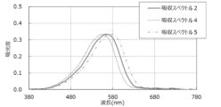
- FIG. 1 is a schematic diagram showing an outline of one embodiment of a liquid crystal display device having an optical filter of the present invention.
- FIG. 2 is a graph showing the waveforms of an absorption spectrum 2 using dye D-2, an absorption spectrum 4 using virtual dye-1, and an absorption spectrum 5 using virtual dye-2.
- the light-absorbing filter of the present invention contains a resin, a dye (hereinafter also simply referred to as "dye") having a main absorption wavelength band in the wavelength range of 400 to 700 nm, and a compound that generates radicals when irradiated with ultraviolet light, and the dye includes at least two types of dyes whose hues are complementary to each other.
- a dye hereinafter also simply referred to as "dye” having a main absorption wavelength band in the wavelength range of 400 to 700 nm
- the dye includes at least two types of dyes whose hues are complementary to each other.
- the main absorption wavelength band of the dye is the main absorption wavelength band of the dye measured in the state of a light-absorbing filter. Specifically, it is measured in the state of a light-absorbing filter with a substrate under the conditions described in the section on absorbance of the light-absorbing filter in the examples described later.
- the above-mentioned "dye” is dispersed (preferably dissolved) in the above-mentioned resin, thereby making the light absorbing filter into a layer exhibiting a specific absorption spectrum derived from the dye. This dispersion may be random, regular, or the like.
- the light absorbing filter of the present invention is a filter in which a compound that generates radicals when irradiated with ultraviolet light is dispersed (preferably dissolved) in a resin, so that when irradiated with ultraviolet light, it generates radicals, which react with a dye and cause the dye to undergo a chemical change, fading the dye and becoming decolorized.
- the dye has the property of undergoing a chemical change when irradiated with ultraviolet light, making it possible to decolorize it.
- the dye contained in the light-absorbing filter of the present invention includes at least two kinds of dyes whose hues are in a complementary relationship with each other.
- the light-absorbing filter of the present invention contains three or more kinds of dyes, it is sufficient that at least two kinds of dyes among the three or more kinds of dyes have mutually complementary hues.
- "hues are complementary to each other” means that in a chromaticity diagram of the CIE 1976 L * a * b * color space, the two dyes are present in quadrants opposite each other with respect to the origin, and the absolute value of the difference in the slope of the chromaticity diagram of the dyes defined by the following formula (A) is 1.2 or less.
- a * and b * in the following formula respectively mean the color shades (a * , b * ) of transmitted light, and are values measured and calculated by simulating the transmittance of a light-absorbing filter containing a single dye, using the method described in the Examples below.
- Formula (A) (slope on chromaticity diagram) (b * ) / (a * )
- the absolute value of the difference in slope on the chromaticity diagram is preferably 1.0 or less, more preferably 0.5 or less, and even more preferably 0.3 or less.
- At least two kinds of dyes contained in the light absorbing filter of the present invention are present in quadrants on opposite sides of the origin in the chromaticity diagram of the CIE 1976 L * a * b * color space, and the absolute value of the difference in slope on the chromaticity diagram is 1.2 or less, so that when an optical filter having a light absorbing portion and a light absorbing loss portion at a desired position is produced, the total amount of dye added required to show a desired reflectance and adjust the reflection color of the light absorbing portion to a neutral color can be kept low. Therefore, when the optical filter of the present invention is obtained from the light absorbing filter of the present invention, the effect of being able to decolorize the dye with a smaller amount of ultraviolet irradiation is expected in order to obtain a desired light absorbing loss portion.
- the compound that generates radicals by ultraviolet irradiation contains a compound A having an acid group and a compound B having a structure capable of forming a hydrogen bond with the acid group contained in the compound A, as described below, the efficiency of generating radical species by ultraviolet irradiation is improved compared to the case of using a commonly used photoradical generator such as a benzophenone compound. Therefore, even when ultraviolet irradiation is performed under mild temperature conditions such as room temperature, sufficient radical species are generated, and these radical species react directly or indirectly with the dye, causing the dye to decompose, resulting in fading and decolorization of the dye.
- the compound A having an acid group when the compound A having an acid group is bonded to a polymer constituting the resin, radicals are generated in the vicinity of the dye by irradiation with ultraviolet light, and the radicals have the effect of easily reacting with the dye.
- compound B having a structure capable of forming a hydrogen bond with the acid group contained in compound A forms a hydrogen bond with compound A and is dispersed (preferably dissolved) in the resin, or when compound A containing the acid group is bonded to a polymer constituting the resin, forms a hydrogen bond with compound A in the resin, and when irradiated with ultraviolet light, generates a radical, and the generated radical reacts with a nearby dye, so that the radical becomes more likely to react with the dye, and the dye can be faded and decolorized more efficiently.
- the at least two kinds of dyes which are included in the dye having a main absorption wavelength band in the wavelength range of 400 to 700 nm and have a complementary hue, preferably include at least one of an azo dye represented by any one of general formulas (i) to (iv) described later and an indoaniline dye represented by general formula (v) described later.
- the azo dye represented by general formula (i) described later is a dye having a main absorption wavelength band in the wavelength range of about 400 to 500 nm
- the azo dye represented by any one of general formulas (ii) to (iv) described later is a dye having a main absorption wavelength band in the wavelength range of about 450 to 600 nm
- the indoaniline dye represented by general formula (v) described later is a dye having a main absorption wavelength band in the wavelength range of about 580 to 700 nm.
- excellent decolorization properties can be exhibited even when irradiated with ultraviolet light in a mild environment at room temperature (meaning 10 to 30° C.).
- the azo dye represented by any of the general formulas (ii) to (iv) described below has a structure in which an electron-donating group (amino group) is substituted at one end of the chromophore and an electron-withdrawing group (thiazole group or isothiazole group) is substituted at the other end.
- an electron-donating group amino group
- thiazole group or isothiazole group an electron-withdrawing group
- the azo dye represented by any one of the general formulae (ii) to (iv) described below also easily generates radicals due to the above-mentioned "Captodative Effect", and is therefore considered to have an excellent decolorization rate when irradiated with ultraviolet light.
- the indoaniline dye represented by the general formula (v) described below also has a structure in which an electron-donating group (amino group) is substituted at one end of the chromophore and an electron-withdrawing group (carbonyl group) is substituted at the other end, and due to the above-mentioned "Captodative Effect", an excellent decolorization rate is obtained even when irradiated with ultraviolet light under mild temperature conditions such as room temperature.
- the azo dye represented by any one of the general formulae (ii) to (iv) described below and the indoaniline dye represented by the general formula (v) described below themselves are considered to have excellent decolorization properties because they hardly cause secondary absorption associated with the decomposition of the dye.
- the dyes having a main absorption wavelength band in the wavelength range of 400 to 700 nm described in Patent Document 1 the dyes having a main absorption wavelength band in the wavelength range of 400 to 700 nm described in Patent Document 1 is described as a dye having a main absorption wavelength band in the wavelength range of approximately 400 to 500 nm.
- the light absorption filter of the present invention contains an azo dye represented by the general formula (i) described later instead of the benzylidene dye or cinnamylidene dye represented by the general formula (V) described in Patent Document 1, it has a main absorption wavelength band in the wavelength range of approximately 400 to 500 nm, and can exhibit excellent decolorization property even when irradiated with ultraviolet light at room temperature (meaning 10 to 30° C.), which is a mild environment.
- the light-absorbing filter of the present invention contains an azo dye represented by any one of (ii) to (iv) below or an indoaniline dye represented by general formula (v) below, it has a main absorption wavelength band in a wavelength region of approximately 450 to 700 nm, and even when irradiated with ultraviolet light in a mild environment, that is, room temperature (meaning 10 to 30° C.), it can exhibit excellent decolorization properties comparable to those of a light-absorbing filter containing a squaraine dye represented by general formula (1) described in Patent Document 1.
- ⁇ Dye having main absorption wavelength band in wavelength range of 400 to 700 nm Specific examples of dyes having a main absorption wavelength band in the wavelength range of 400 to 700 nm for use in the present invention include tetraazaporphyrin (TAP)-based, squaraine (SQ)-based, cyanine (CY)-based, benzylidene-based, cinnamylidene-based, azo-based and indoaniline-based pigments (dyes).
- TAP tetraazaporphyrin
- SQ squaraine
- CY cyanine
- benzylidene-based benzylidene-based
- cinnamylidene-based cinnamylidene-based
- azo-based and indoaniline-based pigments indoaniline-based pigments
- the light absorbing filter of the present invention preferably contains at least one (preferably at least two) of an azo dye represented by any one of the following general formulas (i) to (iv) and an indoaniline dye represented by the following general formula (v) as the dye, from the viewpoint of the low generation of secondary colored structures due to the decomposition of the dye, and more preferably contains at least one (preferably at least two) of an azo dye represented by any one of the following general formulas (i), (ii) and (iv) and an indoaniline dye represented by the following general formula (v).
- a form containing a squaraine dye represented by the following general formula (1) as an optional component is also preferred.
- the part irradiated with ultraviolet light can be efficiently decolorized and colorless. That is, when at least one of an azo dye represented by any one of the following general formulas (i) to (iv) (preferably an azo dye represented by any one of the following general formulas (i), (ii) and (iv)) and an indoaniline dye represented by the following general formula (v) is used as the dye, and when a squaraine dye represented by the following general formula (1) is further used as an optional component, the optical filter of the present invention can be suitably produced by exposing the light-absorbing filter of the present invention to ultraviolet light through a mask.
- the color of the reflected light can be adjusted to be more neutral, which is preferable.
- Each of the azo dye represented by the following general formula (i), the azo dye represented by the following general formula (ii), the azo dye represented by the following general formula (iii), the azo dye represented by the following general formula (iv), and the indoaniline dye represented by the following general formula (v), which can be contained in the light-absorbing filter of the present invention may be one type or two or more types. Furthermore, in the case where the light absorbing filter of the present invention contains a squaraine dye represented by the following general formula (1), the squaraine dye represented by the following general formula (1) may be one type or two or more types.
- the light absorbing filter of the present invention may contain dyes other than the azo dye represented by any one of general formulas (i) to (iv), the indoaniline dye represented by general formula (v), and the squaraine dye represented by general formula (1).
- the cations are delocalized and multiple tautomer structures exist. Therefore, in the present invention, if at least one tautomer structure of a dye fits into each general formula, the dye is considered to be a dye represented by each general formula. Therefore, a dye represented by a specific general formula can also be said to be a dye whose at least one tautomer structure can be represented by a specific general formula. In the present invention, the dye represented by a general formula may have any tautomer structure as long as at least one of the tautomer structures fits into this general formula.
- R 17 and R 18 each independently represent a hydrogen atom or a monovalent substituent.
- R 19 represents a hydrogen atom, an aliphatic group, an aryl group, a heterocyclic group, a carbamoyl group, an alkoxycarbonyl group, an aryloxycarbonyl group, an acyl group, an alkylsulfonyl group, an arylsulfonyl group, or a sulfamoyl group.
- Q represents a residue of a diazo component.
- R 17 to R 19 and Q do not have a squaraine structure.
- the above-mentioned squaraine structure refers to the structure of a squaraine dye.
- a squaraine dye is a dye having a structure in which a skeleton derived from squaric acid is located at the center of a ⁇ -conjugated system.
- a squaraine dye represented by the general formula (1) described below can be mentioned.
- Examples of the monovalent substituent which may be taken as R 17 and R 18 include a halogen atom, an aliphatic group, an aryl group, a heterocyclic group, a cyano group, a carboxy group, a carbamoyl group, an aliphatic oxycarbonyl group, an aryloxycarbonyl group, an acyl group, a hydroxy group, an aliphatic oxy group, an aryloxy group, an acyloxy group, a carbamoyloxy group, a heterocyclic oxy group, an amino group (-NH 2 ), an aliphatic amino group, an arylamino group, a heterocyclic amino group, an acylamino group, a carbamoylamino group, a sulfamoylamino group, an aliphatic oxycarbonylamino group, an aryloxycarbonylamino group, an aliphatic sulfonylamino group, an
- an aliphatic group, an aryl group, a heterocyclic group, a cyano group, a carbamoyl group, an aliphatic oxycarbonyl group, an aryloxycarbonyl group, an acyl group, an aliphatic oxy group, an aryloxy group, an aliphatic amino group, or an arylamino group is preferred.
- the substituents which can be adopted as these R 17 and R 18 may be further substituted.
- the aliphatic groups which can be taken as R 17 to R 19 may further have a monovalent substituent, may be saturated or unsaturated, and may be cyclic. Specific examples include alkyl groups, substituted alkyl groups, alkenyl groups, substituted alkenyl groups, alkynyl groups, substituted alkynyl groups, aralkyl groups, and substituted aralkyl groups.
- the total number of carbon atoms in the aliphatic group is preferably 1 to 30, and more preferably 1 to 16.
- the aliphatic group examples include a methyl group, an ethyl group, a butyl group, an isopropyl group, a t-butyl group, a hydroxyethyl group, a methoxyethyl group, a cyanoethyl group, a trifluoromethyl group, a 3-sulfopropyl group, a 4-sulfobutyl group, a 2-(2-hydroxyethoxy)ethyl group, a 2-(2-(acetyloxy)ethoxy)ethyl group, a cyclohexyl group, a benzyl group, a 2-phenethyl group, a vinyl group, and an allyl group.
- examples of the monovalent substituent that may be possessed include the monovalent substituents that may be taken as R 17 and R 18 , and the same applies to the following explanation of the monovalent substituent that may be possessed.
- examples of the monovalent substituent that may be possessed are preferably an alkoxy group, an acyloxy group, a hydroxy group, etc.
- these substituents may further have a substituent, and examples of the preferred substituents include an alkoxy group, an acyloxy group, a hydroxy group, etc.
- the aryl group which can be taken as R 17 to R 19 may further have a monovalent substituent, and is preferably an aryl group having a total carbon number of 6 to 30, more preferably 6 to 16.
- the heterocyclic group which can be taken as R 17 to R 19 may be a saturated or unsaturated aliphatic ring group, or may be an aromatic ring group, and is preferably an aromatic heterocyclic group.
- ring-constituting atoms constituting the heterocyclic group include those containing at least one heteroatom such as a nitrogen atom, a sulfur atom, or an oxygen atom, and may further have a monovalent substituent.
- the heterocyclic group is preferably a heterocyclic group having a total of 1 to 30 carbon atoms, and more preferably a heterocyclic group having 1 to 15 carbon atoms. Specific examples include a 2-pyridyl group, a 2-thienyl group, a 2-thiazolyl group, a 2-benzothiazolyl group, a 2-benzoxazolyl group, and a 2-furyl group.
- the carbamoyl groups which can be represented by R 17 to R 19 include unsubstituted carbamoyl groups (—CONH 2 ) as well as carbamoyl groups substituted with an aliphatic group, an aryl group, or the like.
- the carbamoyl group which can be represented by R 17 to R 19 may further have a monovalent substituent and is preferably a carbamoyl group having a total of 1 to 30 carbon atoms, more preferably a carbamoyl group having 1 to 16 carbon atoms. Specific examples include a methylcarbamoyl group, a dimethylcarbamoyl group, a phenylcarbamoyl group, and an N-methyl-N-phenylcarbamoyl group.
- the aliphatic oxycarbonyl group which can be represented by R 17 and R 18 may further have a monovalent substituent, may be saturated or unsaturated, may be cyclic, and is preferably an aliphatic oxycarbonyl group having a total of 2 to 30 carbon atoms, more preferably an aliphatic oxycarbonyl group having a total of 2 to 16 carbon atoms. Specific examples include a methoxycarbonyl group, an ethoxycarbonyl group, and a 2-methoxyethoxycarbonyl group.
- the alkoxycarbonyl group which can be taken as R 19 may further have a monovalent substituent, may be saturated or unsaturated, may be cyclic, and is preferably an alkoxycarbonyl group having a total of 2 to 30 carbon atoms, more preferably an alkoxycarbonyl group having a total of 2 to 16 carbon atoms. Specific examples include a methoxycarbonyl group, an ethoxycarbonyl group, and a 2-methoxyethoxycarbonyl group.
- the aryloxycarbonyl group which can be represented by R 17 to R 19 may further have a monovalent substituent, and is preferably an aryloxycarbonyl group having a total of 7 to 30 carbon atoms, more preferably an aryloxycarbonyl group having 7 to 16 carbon atoms. Specific examples include a phenoxycarbonyl group, a 4-methylphenoxycarbonyl group, and a 3-chlorophenoxycarbonyl group.
- the acyl groups which can be taken as R 17 to R 19 include an aliphatic carbonyl group, an arylcarbonyl group, and a heterocyclic carbonyl group, and preferably have a total carbon number of 1 to 30, more preferably have a total carbon number of 1 to 16. Specific examples include an acetyl group, a methoxyacetyl group, a thienoyl group, and a benzoyl group.
- the aliphatic sulfonyl group which can be represented by R 17 and R 18 may further have a monovalent substituent, may be saturated or unsaturated, may be cyclic, and preferably has a total of 1 to 30 carbon atoms, more preferably has a total of 1 to 16 carbon atoms. Specific examples include a methanesulfonyl group, a methoxymethanesulfonyl group, and an ethoxyethanesulfonyl group.
- the alkylsulfonyl group which can be taken as R 19 may further have a monovalent substituent, may be saturated or unsaturated, may be cyclic, and preferably has a total of 1 to 30 carbon atoms, more preferably has a total of 1 to 16 carbon atoms.
- Specific examples include a methanesulfonyl group, a methoxymethanesulfonyl group, and an ethoxyethanesulfonyl group.
- the arylsulfonyl group which can be represented by R 17 to R 19 may further have a monovalent substituent and preferably has a total of 6 to 30 carbon atoms, more preferably has a total of 6 to 18 carbon atoms.
- Specific examples include benzenesulfonyl and toluenesulfonyl groups.
- Sulfamoyl groups which can be taken as R 17 to R 19 include, in addition to unsubstituted sulfamoyl groups (—SO 2 NH 2 ), carbamoyl groups substituted with an aliphatic group, an aryl group, or the like.
- the sulfamoyl group which can be represented by R 17 to R 19 may further have a monovalent substituent and preferably has a total of 0 to 30 carbon atoms, more preferably has a total of 0 to 16 carbon atoms. Specific examples include an unsubstituted sulfamoyl group, a dimethylsulfamoyl group, and a di-(2-hydroxyethyl)sulfamoyl group.
- the imido group which can be taken as R 17 and R 18 may further have a monovalent substituent, and is preferably a 5- or 6-membered ring imido group.
- the imido group preferably has a total of 4 to 30 carbon atoms, more preferably 4 to 20 carbon atoms. Specific examples include succinimide and phthalimide groups.
- aliphatic group in the aliphatic oxy group aliphatic amino group, aliphatic oxycarbonylamino group, aliphatic sulfonylamino group, and aliphatic thio group which can be taken as R 17 and R 18
- the descriptions of the aliphatic groups which can be taken as R 17 to R 19 can be applied.
- the aryl group in the aryloxy group arylamino group, aryloxycarbonylamino group, arylsulfonylamino group and arylthio group which can be taken as R 17 and R 18
- the descriptions of the aryl group which can be taken as R 17 to R 19 can be applied.
- the descriptions of the acyl group which can be taken as R 17 to R 19 can be applied.
- the carbamoyl group in the carbamoyloxy group and carbamoylamino group which can be taken as R 17 and R 18 the descriptions of the carbamoyl groups which can be taken as R 17 to R 19 can be applied.
- the heterocyclic group in the heterocyclic oxy group heterocyclic amino group and heterocyclic thio group which can be taken as R 17 and R 18
- the descriptions of the heterocyclic groups which can be taken as R 17 to R 19 can be applied.
- the sulfamoyl group in the sulfamoylamino group which can be taken as R 17 and R 18 the descriptions of the sulfamoyl groups which can be taken as R 17 to R 19 can be applied.
- the diazo component residue represented by Q means a residue of the diazo component "Q-NH 2 ".
- Q is preferably an aryl group or an aromatic heterocyclic group.
- the aromatic hydrocarbon ring constituting the aryl group that can be taken as Q may be a monocyclic ring or a condensed ring, and is preferably a monocyclic ring.
- An aryl group having a total carbon number of 6 to 30 is preferable, and an aryl group having a total carbon number of 6 to 16 is more preferable.
- a phenyl group is preferable.
- the aryl group that can be taken as Q may have a substituent, and preferable examples of the substituent that may be had include a sulfamoyl group (preferably an alkylsulfamoyl group or a dialkylsulfamoyl group), a sulfonyl group (preferably an alkylsulfonyl group), and a cyano group.
- a sulfamoyl group preferably an alkylsulfamoyl group or a dialkylsulfamoyl group
- a sulfonyl group preferably an alkylsulfonyl group
- cyano group cyano group
- the aromatic heterocyclic group that can be taken as Q is preferably an aromatic ring group containing at least one heteroatom such as a nitrogen atom, a sulfur atom, or an oxygen atom as a ring-constituting atom constituting the heterocyclic group, and is preferably constituted by a 5- to 6-membered ring.
- the number of carbon atoms in the aromatic heterocyclic group is preferably 1 to 25, more preferably 1 to 15.
- the aromatic heterocycle constituting the aromatic heterocyclic group may be a monocycle or a condensed ring, and is preferably a monocycle.
- aromatic heterocyclic group examples include a pyrazole group, a 1,2,4-triazole group, an isothiazole group, a benzoisothiazole group, a thiazole group, a benzothiazole group, an oxazole group, and a 1,2,4-thiadiazole group.
- Examples of the azo dye represented by the above general formula (i) include the following exemplary compounds (B-12) to (B-16), (B-18), and (B-19). However, the present invention is not limited to these.
- R 21 to R 24 , R 26 and R 27 each represent a hydrogen atom, a halogen atom, a cyano group, a nitro group, a carboxy group, a sulfo group, -OR 108 , -SR 109 , -NR 110 R 111 , -S( ⁇ O) 2 NR 112 R 113 , -C( ⁇ O)NR 114 R 115 , -NHC( ⁇ O)R 116 , -C( ⁇ O)OR 117 , -O(CH 2 CH 2 O) n R 118 , -O(CH 2 CH 2 S) n R 119 , -S(CH 2 CH 2 O) n R 120 and -S(CH 2 CH 2 S) n R 121 .
- R 108 to R 121 each represent a hydrogen atom, a non-cyclic hydrocarbon group, a monocyclic hydrocarbon group, a condensed polycyclic hydrocarbon group or a heterocyclic group, and n is a positive integer.
- the acyclic hydrocarbon group, the monocyclic hydrocarbon group, the condensed polycyclic hydrocarbon group and the heterocyclic group include a halogen atom, a cyano group, a nitro group, a carboxy group, a sulfo group, -OR 108 , -SR 109 , -NR 110 R 111 , -S( ⁇ O) 2 NR 112 R 113 , -C( ⁇ O)NR 114 R 115 , -NHC( ⁇ O)R 116 , -C( ⁇ O)OR 117 , -O(CH 2 CH 2 O) n R 118 , -O(CH 2 CH 2 S) n R 119 , -S(CH 2 CH 2 O) n R 120 and -S(CH 2 CH 2 S) n R 121
- the aryl group may have one or more of acyclic hydrocarbon groups, monocyclic hydrocarbon groups, condensed polycyclic hydrocarbon groups, and hetero
- the acyclic hydrocarbon group which can be taken as R 21 to R 24 , R 26 , R 27 and R 108 to R 121 means an acyclic alkyl group in which one hydrogen atom has been removed from an acyclic alkane.
- the acyclic alkyl group may have a ring structure as a substituent.
- the number of carbon atoms in the acyclic alkyl group is preferably 1 to 30, more preferably 1 to 20, still more preferably 1 to 12, particularly preferably 1 to 8, and of these, 1 to 6 is preferred.
- the monocyclic hydrocarbon group which may be taken as R 21 to R 24 , R 26 , R 27 and R to R 121 means a monocyclic cycloalkyl group, a monocyclic cycloalkenyl group, a monocyclic cycloalkynyl group or a monocyclic aryl group which is a group in which one hydrogen atom has been removed from a monocyclic aliphatic hydrocarbon ring (which may be any of a monocyclic cycloalkane, a monocyclic cycloalkene and a monocyclic cycloalkyne) or a monocyclic aromatic hydrocarbon ring.
- the number of carbon atoms in the monocyclic cycloalkyl group, monocyclic cycloalkenyl group, and monocyclic cycloalkynyl group is not particularly limited as long as it is structurally possible, but is more preferably 3 to 30, more preferably 3 to 20, and even more preferably 3 to 16.
- the number of carbon atoms in the monocyclic aryl group is more preferably 6 to 30, more preferably 6 to 20, and even more preferably 6 to 16.
- the fused polycyclic hydrocarbon group which may be taken as R 21 to R 24 , R 26 , R 27 and R to R 121 means a fused polycyclic cycloalkyl group, a fused polycyclic cycloalkenyl group, a fused polycyclic cycloalkynyl group or a fused polycyclic aryl group which is a group in which one hydrogen atom has been removed from a fused polycyclic aliphatic hydrocarbon ring (which may be any of a fused polycyclic cycloalkane, a fused polycyclic cycloalkene and a fused polycyclic cycloalkyne) or a fused polycyclic aromatic hydrocarbon ring.
- the number of carbon atoms in the fused polycyclic cycloalkyl group, the fused polycyclic cycloalkenyl group, and the fused polycyclic cycloalkynyl group is not particularly limited as long as it is structurally possible, but is more preferably 8 to 30, and more preferably 8 to 20.
- the number of carbon atoms in the fused polycyclic aryl group is more preferably 12 to 30, and more preferably 12 to 20.
- the heterocyclic groups which can be taken as R 21 to R 24 , R 26 , R 27 and R 108 to R 121 the descriptions of the heterocyclic groups which can be taken as R 17 to R 19 in the above general formula (i) can be applied.
- n is preferably an integer of 1 to 12, more preferably an integer of 1 to 6, and even more preferably an integer of 1 to 3.
- R 21 is preferably a cyano group, a nitro group, -OR 108 , an acyclic hydrocarbon group (preferably an acyclic alkyl group or an acyclic alkenyl group) or a heterocyclic group, more preferably a cyano group or a nitro group, or an acyclic alkyl group substituted with a halogen atom (preferably an alkyl group substituted with a fluorine atom), and further preferably a cyano group.
- an acyclic hydrocarbon group preferably an acyclic alkyl group or an acyclic alkenyl group
- a heterocyclic group more preferably a cyano group or a nitro group
- a halogen atom preferably an alkyl group substituted with a fluorine atom
- R 22 is preferably a hydrogen atom, a cyano group, an acyclic hydrocarbon group (preferably an acyclic alkyl group) or a monocyclic hydrocarbon group, more preferably a hydrogen atom, an alkyl group or an aryl group, and even more preferably an alkyl group or an aryl group. At least one of R 21 and R 22 is preferably a cyano group, a nitro group, or a non-cyclic alkyl group substituted with a halogen atom, a cyano group, or a nitro group.
- R 23 is preferably a hydrogen atom, -OR 108 , -SR 109 , -NR 110 R 111 , -C( ⁇ O)NR 114 R 115 , -NHC( ⁇ O)R 116 , -O(CH 2 CH 2 O) n R 118 , -O(CH 2 CH 2 S) n R 119 , -S(CH 2 CH 2 O) n R 120 , -S(CH 2 CH 2 S) n R 121 or an acyclic hydrocarbon group (preferably an acyclic alkyl group), more preferably a hydrogen atom, -OR 108 , -SR 109 , -NR 110 R 111 , -NHC( ⁇ O)R 116 or an acyclic alkyl group, and more preferably -NHC( ⁇ O)R More preferably, R 108 to R 111 , R 116 and R 118 to R 121 are each preferably acyclic alkyl groups .
- R 24 and R 27 are preferably a hydrogen atom.
- R 26 is preferably a hydrogen atom, -OR 108 , -SR 109 , -NR 110 R 111 , -NHC( ⁇ O)R 116 , -O(CH 2 CH 2 O) n R 118 , -O(CH 2 CH 2 S) n R 119 , -S(CH 2 CH 2 O) n R 120 , -S(CH 2 CH 2 S) n R 121 or an acyclic hydrocarbon group (preferably an acyclic alkyl group), more preferably a hydrogen atom, -OR 108 or -SR 109 , and even more preferably a hydrogen atom.
- R 108 to R 111 , R 116 and R 118 to R 121 are preferably acyclic alkyl groups.
- R 110 is preferably an acyclic alkyl group
- R 111 is preferably an acyclic alkyl group, more preferably an unsubstituted acyclic alkyl group, or an acyclic alkyl group having -OR 108 , a monocyclic hydrocarbon group or a condensed polycyclic hydrocarbon group as a substituent, wherein R 108 is preferably a hydrogen atom or an acyclic alkyl group.
- dye represented by formula (ii) include the compounds used in the examples described below, as well as the compounds described in paragraphs [0023] to [0034] of JP-A-5-257180, and the compounds described in paragraphs [0050] and [0052] of JP-A-2013-129712, compound D-18 described in paragraph [0055], and the compound described in paragraph [0056].
- the present invention is not limited to these.
- R 31 represents a hydrogen atom, an alkyl group, an alkoxy group, a cyano group, a carbonyl group (preferably an alkyloxycarbonyl group or an aryloxycarbonyl group), an aromatic group or a heterocyclic group.
- R 32 represents a hydrogen atom, an alkyl group, an alkoxy group, a cyano group, a nitro group, a carbonyl group (preferably an alkyloxycarbonyl group or an aryloxycarbonyl group), an aromatic group or a heterocyclic group.
- R 34 and R 35 each independently represent a hydrogen atom, an alkyl group or an aromatic group.
- R 37 represents a hydrogen atom, an alkyl group, an alkoxy group, a cyano group, a carbonyl group (preferably an alkyloxycarbonyl group or an aryloxycarbonyl group), an acylamino group or an aromatic group.
- R 34 and R 35 may be bonded to each other to form a ring.
- R 1 and R 2 in relation to the general formula (1) described in JP-A-2013-129712 can be directly applied to R 31 and R 32 , respectively, and the description of R 4 , R 5 and R 7 in relation to the general formula (3) described in JP-A-2013-129712 can be directly applied to R 34 , R 35 and R 37 , respectively.
- R 37 can be the following acylamino group in addition to the hydrogen atom, alkyl group, alkoxy group, cyano group, carbonyl group, and aromatic group that R 7 in the general formula (3) described in JP2013-129712A can be.
- the acylamino group which can be represented by R 37 preferably has 1 to 12 carbon atoms, and more preferably has 1 to 6 carbon atoms.
- the alkyl group which can be represented by R 31 , R 32 and R 37 preferably has 1 to 20 carbon atoms, more preferably 1 to 12 carbon atoms, and particularly preferably 1 to 6 carbon atoms.
- the alkoxy group which can be represented by R 31 , R 32 and R 37 preferably has 1 to 20 carbon atoms, more preferably 1 to 12 carbon atoms, and particularly preferably 1 to 6 carbon atoms.
- the alkyloxycarbonyl group which can be represented by R 31 , R 32 and R 37 preferably has 2 to 30 carbon atoms, more preferably 2 to 20 carbon atoms, further preferably 2 to 12 carbon atoms, and particularly preferably 2 to 7 carbon atoms.
- the alkyl group which can be represented by R 34 and R 35 preferably has 1 to 30 carbon atoms, more preferably 1 to 20 carbon atoms, and even more preferably 1 to 12 carbon atoms.
- R 31 is preferably an alkyl group or an aryl group, more preferably an alkyl group.
- R 32 is preferably an alkyl group or a cyano group, more preferably a cyano group.
- R 34 and R 35 are preferably a hydrogen atom or an alkyl group, more preferably an alkyl group.
- R 37 is preferably a hydrogen atom, an alkyl group, an acylamino group or an aromatic group, more preferably a hydrogen atom or an alkyl group, and even more preferably an alkyl group.
- R 41 to R 44 , R 46 and R 47 each represent a hydrogen atom, a halogen atom, a cyano group, a nitro group, a carboxy group, a sulfo group, -OR 208 , -SR 209 , -NR 210 R 211 , -S( ⁇ O) 2 NR 212 R 213 , -C( ⁇ O)NR 214 R 215 , -NHC( ⁇ O)R 216 , -C( ⁇ O)OR 217 , -O(CH 2 CH 2 O) n R 218 , -O(CH 2 CH 2 S) n R 219 , -S(CH 2 CH 2 O) n R 220 and -S(CH 2 CH 2 S) n R 221 .
- R 208 to R 221 each represent a hydrogen atom, a non-cyclic hydrocarbon group, a monocyclic hydrocarbon group, a condensed polycyclic hydrocarbon group or a heterocyclic group, and n is a positive integer.
- R 208 to R 211 , R 216 and R 218 to R 221 are preferably acyclic alkyl groups.
- R 210 is preferably an acyclic alkyl group
- R 211 is preferably an acyclic alkyl group, more preferably an unsubstituted acyclic alkyl group (including an acyclic alkyl group substituted with an acyclic alkyl group), or -OR 208 , an acyclic alkyl group having a monocyclic hydrocarbon group or a condensed polycyclic hydrocarbon group as a substituent.
- R 208 is preferably a hydrogen atom or an acyclic alkyl group.
- R 44 and/or R 46 in general formula (iv) may be bonded to R 210 and/or R 211 in -NR 210 R 211 located at the ortho position relative to R 44 and R 46 on the benzene ring to form a ring.
- the ring that may be formed is preferably a 5- or 6-membered ring, and may be saturated or unsaturated, and is preferably a saturated 6-membered ring.
- the ring that may be formed may further have a substituent, and preferably has, for example, an alkyl group.
- the ring is preferably formed by bonding R 46 to R 211 in --NR 210 R 211 located at the ortho position relative to R 44 and R 46 on the benzene ring to form a saturated 6-membered ring.
- Q1 represents a group of atoms necessary to form a 5- to 7-membered nitrogen-containing heterocycle together with the carbon atom to which it is bonded, including at least one nitrogen atom.
- R 51 represents an acyl group, an alkoxycarbonyl group, an aryloxycarbonyl group, an aminocarbonyl group or a sulfonyl group
- R 52 represents a hydrogen atom or an alkyl group
- R 53 to R 57 represent a hydrogen atom, an alkyl group, an alkoxy group, an acylamino group, an alkylsulfonylamino group or a halogen atom
- R 58 and R 59 represent a hydrogen atom, an alkyl group or an aryl group.
- R51 and R53 , R54 and R55 and/or R55 and R59 , or R58 and R59 may be bonded to each other to form a ring. That is, it means that R51 and R53 may be bonded to each other to form a ring, R54 and R55 and/or R55 and R59 may be bonded to each other to form a ring, or R58 and R59 may be bonded to each other to form a ring.
- R 1 to R 6 , R 8 , R 9 and Q 1 in general formula (I) described in JP-A-2-92686 can be directly applied to R 51 to R 56 , R 58 , R 59 and Q 1 , respectively, unless otherwise specified.
- R 53 to R 56 can be the following acylamino group and alkylsulfonylamino group in addition to the hydrogen atom, alkyl group, alkoxy group and halogen atom which R 3 to R 6 in the general formula (I) described in JP-A-2-92686 can be.
- the acylamino group which can be represented by R 53 to R 57 preferably has 1 to 12 carbon atoms, and more preferably has 1 to 6 carbon atoms.
- the alkylsulfonylamino group which can be represented by R 53 to R 57 preferably has 1 to 12 carbon atoms, and more preferably has 1 to 6 carbon atoms.
- R 16 represents a hydrogen atom, an alkyl group, an aryl group, or a heterocyclic group, and a hydrogen atom is preferred.
- the definition and preferred range of each substituent of R 16 are the same as those described in JP-A-2-92686 regarding R 16 in the general formula (I).
- R 51 is preferably an acyl group having 2 to 7 carbon atoms or an alkoxycarbonyl group having 2 to 7 carbon atoms.
- R 52 is preferably a hydrogen atom, and R 53 to R 56 are preferably hydrogen atoms.
- R 57 is preferably an alkoxy group, an acylamino group or an alkylsulfonylamino group, more preferably an alkoxy group or an acylamino group.
- R 58 and R 59 are preferably an alkyl group having 1 to 6 carbon atoms.
- indoaniline dye represented by the above general formula (v) is preferably represented by the following general formula (v-a):
- R 51 , R 53 , R 57 to R 59 and Q 2 have the same meanings as R 51 , R 53 , R 57 to R 59 and Q 2 in general formula (v) above.
- Q2 is preferably -CR 11 R 12 CR 13 R 14 -, -CR 11 R 12 - or -NR 11 -, and more preferably -CR 11 R 12 CR 13 R 14 -.
- R 11 to R 14 each represent a hydrogen atom or an alkyl group having 1 to 4 carbon atoms, and it is preferable that R 11 and R 12 are hydrogen atoms and R 13 and R 14 are alkyl groups having 1 to 4 carbon atoms.
- --CR 11 R 12 CR 13 R 14 -- is bonded to >C ⁇ O on the side of the carbon atom to which R 11 and R 12 are bonded.
- G represents a heterocyclic group which may have a substituent.
- each substituent in the general formula (1) may be directly applied to the descriptions of each substituent of the dye represented by the general formula (1) described in WO 2021/132674.
- the dyes represented by any of the general formulas (2) to (5) described in [0045] to [0070] of WO 2021/132674 and the specific examples thereof can be applied as they are.
- the present invention is not limited to these.
- specific examples of the dye represented by any of the general formulas (3) to (5) include the compounds described in [0071] to [0080] of WO 2021/132674.
- the present invention is not limited to these.
- the dye represented by the above general formula (1) the dye represented by any one of the general formulas (6) to (9) described in [0081] to [0095] of WO 2021/132674 and the specific examples thereof can be applied as they are.
- the present invention is not limited to these.
- the squaraine dye represented by the general formula (1) may be a quencher-containing dye in which the quencher moiety is covalently linked to the dye via a linking group.
- the quencher-containing dye may also be preferably used as the dye. That is, the quencher-containing dye is counted as the dye according to the wavelengths having the main absorption wavelength band.
- the above-mentioned quencher-containing dyes include an electron-donating quencher-containing dye in which the quencher moiety is an electron-donating quencher moiety, and an electron-accepting quencher moiety in which the quencher moiety is an electron-accepting quencher moiety.
- the electron-donating quencher moiety refers to a structural part which donates an electron to the SOMO (Singly Occupied Molecular Orbital) having a lower energy level of two SOMOs of the dye in an excited state, and then receives an electron from the SOMO having a higher energy level of the dye, thereby deactivating the dye in an excited state to the ground state.
- the electron-accepting quencher moiety refers to a structural part which accepts an electron from the SOMO having a higher energy level of two SOMOs of the dye in an excited state, and then donates an electron to the SOMO having a lower energy level of the dye, thereby deactivating the dye in an excited state to the ground state.
- Examples of the electron-donating quencher moiety include the ferrocenyl group in the substituent X that may be possessed by A, B, and G in the general formula (1) described in WO 2021/132674, and the quencher moiety in the quencher compound described in paragraphs [0199] to [0212] and paragraphs [0234] to [0287] of WO 2019/066043, and the ferrocenyl group in the substituent X that may be possessed by A, B, and G in the general formula (1) described in WO 2021/132674 is preferred.
- examples of the electron-accepting quencher moiety include the quencher moiety in the quencher compound described in paragraphs [0288] to [0310] of WO 2019/066043.
- the light-absorbing filter of the present invention preferably contains a dye having a main absorption wavelength band of 400 to 700 nm, and more preferably contains a squaraine dye represented by the following general formula (1A).
- G represents a heterocyclic group which may have a substituent.
- at least one of A and B includes an electron-donating quencher moiety.
- the dye represented by the above general formula (1A) is the same as the dye represented by the above general formula (1), except that at least one of A and B in the dye represented by the above general formula (1) contains an electron-donating quencher portion. Therefore, for the description of A, B, and G in the general formula (1A), the description of A, B, and G in the general formula (1) described in WO 2021/132674 can be applied.
- the description of the dye represented by the general formula (1A) in the description of the dye represented by any of the general formulas (2) to (9), which is a preferred embodiment of the dye represented by the above general formula (1), at least one of the structures corresponding to A and B in the general formula (1) is modified to include an electron-donating quencher portion.
- the electron-donating quencher moiety contained in at least one of A and B is preferably a ferrocenyl group in the substituent X that may be possessed by A, B, and G in the general formula (1) described in WO 2021/132674.
- squaraine dyes represented by general formula (1) that are quencher-containing dyes include the compounds described in paragraphs [0097] to [0114] of WO 2021/132674. However, the present invention is not limited to these.
- the total content of the dyes in the light absorbing filter of the present invention is preferably 0.10% by mass or more, more preferably 0.15% by mass or more, even more preferably 0.20% by mass or more, particularly preferably 0.25% by mass or more, and particularly preferably 0.30% by mass or more.
- the total content of the dyes in the light absorbing filter of the present invention is equal to or more than the above-mentioned preferable lower limit, good light absorption properties such as antireflection effect can be obtained.
- the total content of the above dyes in the light-absorbing filter of the present invention is usually 50% by mass or less, preferably 40% by mass or less, more preferably 30% by mass or less, even more preferably 15% by mass or less, and particularly preferably 10% by mass or less.
- the total content of the dyes in the light-absorbing filter of the present invention is preferably 0.10 to 50 mass%, more preferably 0.15 to 40 mass%, even more preferably 0.20 to 30 mass%, particularly preferably 0.25 to 15 mass%, and especially preferably 0.30 to 10 mass%.
- the total content of at least two types of dyes whose hues are complementary to each other is preferably 0.01 to 50 mass%, more preferably 0.1 to 40 mass%, even more preferably 0.25 to 30 mass%, particularly preferably 0.5 to 20 mass%, and especially preferably 0.5 to 10 mass%.
- all of the dyes may be composed of dyes whose hues are complementary to each other.
- the content of the azo dye represented by the general formula (i) in the light-absorbing filter of the present invention is preferably 0.01 to 30% by mass, more preferably 0.1 to 10% by mass.
- the content of each of the azo dye represented by the general formula (ii), the azo dye represented by the general formula (iii), the azo dye represented by the general formula (iv), and the indoaniline dye represented by the general formula (v) in the light-absorbing filter of the present invention is preferably 0.01 to 30% by mass, more preferably 0.1 to 10% by mass, similar to the content of the azo dye represented by the general formula (i).
- all of the dyes may be composed of at least one of the azo dye represented by any one of the general formulas (i) to (iv) and the indoaniline dye represented by the general formula (v).
- the content of the squaraine dye represented by the above general formula (1) in the light-absorbing filter of the present invention is preferably 0.01 to 30 mass %, more preferably 0.1 to 10 mass %.
- all of the dyes except for the azo dye represented by any one of the above general formulas (i) to (iv) and the indoaniline dye represented by the above general formula (v), may be squaraine dyes represented by the above general formula (1).
- the content of the quencher-containing dye in the light-absorbing filter of the present invention is preferably 0.10% by mass or more, more preferably 0.15% by mass or more, even more preferably 0.20% by mass or more, particularly preferably 0.25% by mass or more, and especially preferably 0.30% by mass or more, from the viewpoint of imparting light absorption properties such as anti-reflection effect.
- the upper limit is preferably 45% by mass or less, preferably 40% by mass or less, more preferably 30% by mass or less, even more preferably 15% by mass or less, and especially preferably 10% by mass or less. That is, the total content of the quencher-containing dye in the light-absorbing filter is preferably 0.10 to 45% by mass, more preferably 0.15 to 40% by mass, even more preferably 0.20 to 30% by mass, particularly preferably 0.25 to 15% by mass, and especially preferably 0.30 to 10% by mass.
- the light absorbing filter of the present invention contains a compound that generates radicals when irradiated with ultraviolet light (in the present invention, this is also simply referred to as a "radical generator").
- the radical generator is not particularly limited as long as it is a compound that generates radicals by irradiation with ultraviolet light and has the function of decolorizing the dye.
- a photoradical generator that may be used in combination with compound B described below can be used as the radical generator.
- the radical generator is a combination of two or more compounds, and the combination of two or more compounds in the light absorbing filter that generates radicals by ultraviolet irradiation as a result of interaction such as complex formation.
- the type of the compound to be combined may be two or more compounds that show different functions in the mechanism of generating radicals by ultraviolet irradiation, and two types are preferable.
- the combination of compound A having an acid group and compound B having a structure that can form hydrogen bonds with the acid group contained in compound A is preferable.
- the light absorbing filter of the present invention contains a compound A having an acid group and a compound B having a structure capable of forming a hydrogen bond with the acid group contained in the compound A, the efficiency of generating radical species by ultraviolet irradiation is improved compared to the case of using the photoradical generator. Therefore, even when ultraviolet irradiation is performed under mild temperature conditions such as room temperature, sufficient radical species are generated, and these radical species react directly or indirectly with the dye, and the dye is decomposed, so that the dye fades and becomes discolored.
- the azo dye represented by any of the general formulas (i), (ii) and (iv) described above, the indoaniline dye represented by the general formula (v) described above, and the squaraine dye represented by the general formula (1) described above that can be contained in the light absorbing filter of the present invention are discolored with almost no secondary absorption associated with the decomposition of the dye.
- Compound A having an acid group and compound B having a structure capable of forming a hydrogen bond with the acid group contained in compound A will be described in detail below.
- Compound A having an acid group The light absorbing filter of the present invention preferably contains, as the radical generator, a compound A having an acid group (in the present invention, also simply referred to as "compound A") together with a compound B having a structure capable of forming a hydrogen bond with the acid group contained in compound A described below.
- the acid group contained in compound A is preferably a proton dissociative group having a pKa of 12 or less.
- Compound A may be a low molecular weight compound or a high molecular weight compound (hereinafter also referred to as a "polymer”), and is preferably a polymer.
- Compound A being a polymer means that compound A is chemically bonded to a polymer constituting the resin contained in the light-absorbing filter of the present invention.
- the molecular weight of compound A is less than 5000, preferably 2000 or less, more preferably 1000 or less, even more preferably 500 or less, and particularly preferably 400 or less. There is no particular restriction on the lower limit, but 100 or more is practical, and 200 or more is preferable.
- the lower limit of the weight-average molecular weight of compound A is 5,000 or more, and from the viewpoint of the physical properties of the optical filter, it is preferably 10,000 or more, and more preferably 15,000 or more.
- the upper limit is not particularly limited, but from the viewpoint of solubility in a solvent, it is preferably 500,000 or less, more preferably 200,000 or less, and even more preferably 150,000 or less. That is, 5,000 to 500,000 is practical and preferable, 10,000 to 200,000 is more preferable, and 15,000 to 150,000 is more preferable.
- acid groups contained in compound A may or may not be anionized in the light absorbing filter, and in the present invention, both anionized and non-anionized acid groups are referred to as acid groups.
- compound A may or may not be anionized in the light absorbing filter.
- Compound A is preferably a compound having a carboxy group, in view of excellent film-forming properties of the light-absorbing filter.
- the compound having a carboxy group is preferably a monomer containing a carboxy group (hereinafter also referred to as a "carboxy group-containing monomer”) or a polymer containing a carboxy group (hereinafter also referred to as a "carboxy group-containing polymer”), and from the viewpoint of the film-forming property of the light-absorbing filter, it is more preferably a carboxy group-containing polymer.
- carboxy groups (-COOH) possessed by the carboxy group-containing monomer and the carboxy group-containing polymer may be anionized or not in the light-absorbing filter, and both anionized carboxy groups ( -COO- ) and non-anionized carboxy groups are referred to as carboxy groups.
- carboxy group-containing polymer may be either anionized or non-anionized in the light absorbing filter, and both anionized and non-anionized carboxy group-containing polymers are referred to as the carboxy group-containing polymer.
- the content of compound A in the light absorbing filter is preferably 1% by mass or more, more preferably 25% by mass or more, even more preferably 30% by mass or more, particularly preferably 45% by mass or more, and especially preferably 50% by mass or more.
- the upper limit of the content of compound A is preferably less than 100% by mass, more preferably 99% by mass or less, and even more preferably 97% by mass or less. That is, it is preferably 1% by mass or more and less than 100% by mass, more preferably 25 to 99% by mass, even more preferably 30 to 97% by mass, particularly preferably 45 to 97% by mass, and especially preferably 50 to 97% by mass.
- the content of compound A in the light absorbing filter is preferably 50% by mass or more and less than 100% by mass, more preferably 60% by mass or more and less than 100% by mass, and even more preferably 70% by mass or more and less than 100% by mass.
- the upper limit is also preferably 99% by mass or less, more preferably 97% by mass or less, even more preferably 95% by mass or less, and particularly preferably 90% by mass or less.
- the compound A may be used alone or in combination of two or more kinds.
- the carboxy group-containing monomer may be a polymerizable compound that contains a carboxy group and one or more (eg, 1 to 15) ethylenically unsaturated groups.
- the ethylenically unsaturated group include a (meth)acryloyl group, a vinyl group, and a styryl group, with a (meth)acryloyl group being preferred.
- the carbonyl bond in the (meth)acryloyl group and the carbonyl bond in the carboxy group may share one carbonyl bond.
- the carboxyl group-containing monomer is preferably a difunctional or higher functional monomer containing a carboxyl group.
- the difunctional or higher functional monomer means a polymerizable compound having two or more (e.g., 2 to 15) ethylenically unsaturated groups in one molecule.
- the number of carboxy groups contained in the carboxy group-containing monomer may be one or more, and for example, 1 to 8 is preferable, 1 to 4 is more preferable, and 1 or 2 is even more preferable.
- the carboxyl group-containing monomer may further have an acid group other than the carboxyl group. Examples of the acid group other than the carboxyl group include a phenolic hydroxyl group, a phosphoric acid group, and a sulfonic acid group.
- the di- or higher functional monomer containing a carboxy group is not particularly limited and can be appropriately selected from known compounds.
- Examples of bifunctional or higher functional monomers containing a carboxy group include trade names ARONIX M-520 and ARONIX M-510 (both manufactured by Toagosei Co., Ltd.).
- trifunctional or higher monomers containing a carboxy group it is also preferable to use a difunctional or higher monomer containing a carboxy group in combination from the viewpoint of better film-forming properties.
- difunctional or higher monomers containing a carboxy group and difunctional or higher monomers containing an acid group include the polymerizable compounds having an acid group described in paragraphs 0025 to 0030 of JP 2004-239942 A. The contents of this publication are incorporated herein by reference.
- the carboxyl group-containing polymer may further have an acid group other than the carboxyl group.
- the acid group other than the carboxyl group include a phenolic hydroxyl group, a phosphoric acid group, and a sulfonic acid group.
- the carboxy group-containing polymer is a copolymer
- the polymer structure may be a random polymer or a regular polymer such as a block polymer.
- the carboxy group-containing polymer preferably has a structural unit having a carboxy group.
- the structural unit having a carboxy group include structural units derived from (meth)acrylic acid, crotonic acid, itaconic acid, maleic acid, or fumaric acid. Among these, structural units derived from (meth)acrylic acid are preferred because of their excellent decolorization properties.
- the content of the structural unit having a carboxy group in the carboxy group-containing polymer is preferably 1 to 100 mol%, more preferably 3 to 65 mol%, still more preferably 5 to 60 mol%, particularly preferably 10 to 60 mol%, and of these, preferably 20 to 55 mol%, when the total of all structural units of the carboxy group-containing polymer is 100 mol%.
- the structural unit having a carboxy group may be used alone or in combination of two or more kinds.
- the carboxyl group-containing polymer preferably has a structural unit having an aromatic ring (preferably an aromatic hydrocarbon ring).
- a structural unit derived from a (meth)acrylate having an aromatic ring specifically, benzyl (meth)acrylate, phenethyl (meth)acrylate, or phenoxyethyl (meth)acrylate, etc. can be mentioned.
- the content of the structural unit having an aromatic ring is preferably 0 to 97 mol%, more preferably 0 to 95 mol%, and even more preferably 0 to 90 mol%, when the total of all structural units of the carboxy group-containing polymer is 100 mol%.
- the aromatic ring-containing structural unit may be used alone or in combination of two or more kinds.
- the carboxyl group-containing polymer also preferably has a structural unit having an alicyclic structure.
- alicyclic structures include a tricyclo[5.2.1.0 2,6 ]decane ring structure (also called tetrahydrodicyclopentadiene; the monovalent group is dicyclopentanyl), a tricyclo[5.2.1.0 2,6 ]decane-3-ene ring structure (also called 5,6-dihydrodicyclopentadiene; the monovalent group is dicyclopentenyl), an isobornane ring structure (the monovalent group is isobornyl), an adamantane ring structure (the monovalent group is adamantyl), and a cyclohexane ring structure (the monovalent group is cyclohexyl).
- Examples of structural units having an alicyclic structure include structural units derived from (meth)acrylates having an alicyclic structure (specifically, dicyclopentanyl (meth)acrylate, dicyclopentenyl (meth)acrylate, isobornyl (meth)acrylate, adamantyl (meth)acrylate, methyladamantyl (meth)acrylate, cyclohexyl (meth)acrylate, etc.).
- the content of the structural unit having an alicyclic structure is preferably 0 to 97 mol%, more preferably 0 to 95 mol%, and even more preferably 0 to 90 mol%, when the total of all structural units of the carboxy group-containing polymer is 100 mol%.
- the structural unit having an alicyclic structure may be used alone or in combination of two or more kinds.
- the carboxyl group-containing polymer may have other structural units in addition to the structural units described above.
- An example of the other structural unit is a structural unit derived from methyl (meth)acrylate.
- the content of the other structural units in the carboxy group-containing polymer is preferably 0 to 70 mol%, more preferably 0 to 50 mol%, and even more preferably 0 to 20 mol%, when the total of all structural units of the carboxy group-containing polymer is 100 mol%.
- the other structural units may be used alone or in combination of two or more kinds.
- the light absorbing filter of the present invention preferably contains, as the radical generator, compound B (also simply referred to as "compound B" in the present invention) having a structure capable of forming a hydrogen bond with an acid group contained in compound A, together with compound A described above.
- Compound B is preferably a compound having a structure in which basicity increases when it absorbs ultraviolet light and enters an excited state. When the basicity of compound B increases in the excited state, the acid group contained in compound A can form a complex with compound B through stronger interaction, thereby making it possible to increase the efficiency of generating radicals.
- the structure of compound B capable of forming a hydrogen bond with the acid group contained in compound A may be the entire structure of compound B or a partial structure constituting a part of compound B.
- Compound B may be a polymer compound (meaning a compound having a molecular weight of 5000 or more) or a low molecular compound (meaning a compound having a molecular weight of less than 5000), and is preferably a low molecular compound.
- the molecular weight of compound B, which is a low molecular weight compound is less than 5,000, preferably less than 1,000, more preferably 500 or less, and even more preferably 350 or less. There is no particular restriction on the lower limit, but it is preferably 65 or more, more preferably 75 or more.
- a preferred range for the molecular weight of compound B, which is a low molecular weight compound is, for example, 65 to 500, more preferably 75 to 350.
- Compound B is preferably an aromatic compound because it has a large molar absorption coefficient for ultraviolet light.
- the aromatic compound is a compound having one or more aromatic rings.
- the aromatic ring may be present in only one unit or in a plurality of units in the compound B. When a plurality of units is present, the aromatic ring may be present, for example, in a side chain of a polymer constituting the resin.
- the aromatic ring may be either an aromatic hydrocarbon ring or an aromatic heterocycle.
- an aromatic heterocycle also referred to as a heteroaromatic ring
- it is a compound having one or more (e.g., 1 to 4) heteroatoms (at least one of nitrogen atom, oxygen atom, sulfur atom, etc.) as ring member atoms (ring constituent atoms), and preferably has one or more (e.g., 1 to 4) nitrogen atoms as ring member atoms.
- unsubstituted aromatic hydrocarbons do not have a structure capable of forming hydrogen bonds with the acid groups contained in compound A, they do not have the function of generating radicals upon irradiation with ultraviolet light, and do not fall under compound B.
- an unsubstituted aromatic hydrocarbon ring in a form in which an unsubstituted aromatic hydrocarbon ring is bonded to a side chain of a polymer constituting a resin does not have a structure capable of forming hydrogen bonds with the acid groups contained in compound A, they do not have the function of generating radicals upon irradiation with ultraviolet light, and do not fall under compound B.
- the aromatic ring preferably has 5 to 15 ring atoms.
- aromatic ring examples include monocyclic aromatic rings such as a pyridine ring, a pyrazine ring, a pyrimidine ring, and a triazine ring; aromatic rings having two condensed rings such as a quinoline ring, an isoquinoline ring, a quinoxaline ring, and a quinazoline ring; and aromatic rings having three condensed rings such as an acridine ring, a phenanthridine ring, a phenanthroline ring, and a phenazine ring.
- monocyclic aromatic rings such as a pyridine ring, a pyrazine ring, a pyrimidine ring, and a triazine ring
- aromatic rings having two condensed rings such as a quinoline ring, an isoquinoline ring, a quinoxaline ring, and a quinazoline ring
- aromatic rings having three condensed rings such as an acrid
- the aromatic ring may have one or more (for example, 1 to 5) substituents, and examples of the substituents include an alkyl group, an aryl group, a halogen atom, an acyl group, an alkoxycarbonyl group, an arylcarbonyl group, a carbamoyl group, a hydroxy group, a cyano group, and a nitro group.
- substituents include an alkyl group, an aryl group, a halogen atom, an acyl group, an alkoxycarbonyl group, an arylcarbonyl group, a carbamoyl group, a hydroxy group, a cyano group, and a nitro group.
- the multiple substituents may be bonded to each other to form a non-aromatic ring.
- a series of aromatic ring structures in which the above-mentioned multiple aromatic rings are bonded through a structure selected from a single bond, a carbonyl bond, and a multiple bond does not fall under the above-mentioned unsubstituted aromatic hydrocarbon ring, nor does it fall under the unsubstituted aromatic hydrocarbon ring in a form in which an unsubstituted aromatic hydrocarbon ring is bonded to a side chain of a polymer constituting the resin.
- compound B include monocyclic aromatic compounds such as pyridine compounds (pyridine and pyridine derivatives), pyrazine compounds (pyrazine and pyrazine derivatives), pyrimidine compounds (pyrimidine and pyrimidine derivatives), and triazine compounds (triazine and triazine derivatives); compounds in which two rings are condensed to form an aromatic ring, such as quinoline compounds (quinoline and quinoline derivatives), isoquinoline compounds (isoquinoline and isoquinoline derivatives), quinoxaline compounds (quinoxaline and quinoxaline derivatives), and quinazoline compounds (quinazoline and quinazoline derivatives); and compounds in which three or more rings are condensed to form an aromatic ring, such as acridine compounds (acridine and acridine derivatives), phenanthridine compounds (phenanthridine and phenanthridine derivatives), phenanthroline compounds (phenanthroline and phenanthroline derivatives), and
- the term "compound” is used to mean not only the compound itself, but also a compound having a substituent (referred to as a "derivative"), including an unsubstituted compound whose structure has been partially changed within a range that does not impair the effects of the present invention. It is presumed that these compounds B form complexes with the aforementioned compound A, and when irradiated with ultraviolet light, generate two radical molecules through the following mechanism. 1) Compound B in an excited state is generated by absorbing ultraviolet light. 2) A hole moves from compound B in the excited state to compound A in the ground state (an electron from compound A moves to the lower energy orbital of the two half-occupied orbitals of compound B in the excited state).
- compound B is preferably at least one of quinoline compounds (quinoline and quinoline derivatives) and isoquinoline compounds (isoquinoline and isoquinoline derivatives).
- the substituents which these compounds may have are preferably an alkyl group, an aryl group, a halogen atom, an acyl group, an alkoxycarbonyl group, an arylcarbonyl group, a carbamoyl group, a hydroxy group, a cyano group, or a nitro group.
- compound B When compound B is a polymer, it may be a polymer in which the specific structure is bonded to the polymer main chain via a single bond or a linking group.
- Compound B, which is a polymer can be obtained, for example, by polymerizing a monomer having a heteroaromatic ring (specifically, a heteroaromatic ring having a vinyl group and/or a (meth)acrylate monomer having a specific structure (preferably a heteroaromatic ring). If necessary, it may be copolymerized with other monomers.
- compound B examples include quinoline, 2-methylquinoline, 4-methylquinoline, 2,4-dimethylquinoline, 2-methyl-4-phenylquinoline, isoquinoline, 1-methylisoquinoline, 3-methylisoquinoline, and 1-phenylisoquinoline.
- the content of compound B is preferably 0.1 to 50 mass %, more preferably 2.0 to 40 mass %, further preferably 4 to 35 mass %, and particularly preferably 8 to 30 mass %, relative to the total mass of the light absorbing filter.
- the pKaH (pKa of the conjugate acid), which is a measure of the basicity of compound B, is preferably from 2.0 to 7.0, more preferably from 3.0 to 6.0, and even more preferably from 4.3 to 5.5, from the viewpoint of achieving both the decolorization property of the ultraviolet irradiated portion and the durability of the dye of the ultraviolet non-irradiated portion.
- the compound B may be used alone or in combination of two or more kinds.
- the light absorbing filter of the present invention may contain a compound that generates radicals when irradiated with ultraviolet light (also referred to as a "photoradical generator" in the present invention) in addition to the compound B.
- the photoradical generator is not particularly limited as long as it is a compound that generates radicals when irradiated with ultraviolet light and has the function of decolorizing the dye.
- the radicals generated may be biradicals in addition to normal radicals.
- photoradical generator compounds commonly used as photoradical polymerization initiators or photoradical generators can be used without particular limitation, and examples thereof include acetophenone generators, benzoin generators, benzophenone generators, phosphine oxide generators, oxime generators, ketal generators, anthraquinone generators, thioxanthone generators, azo compound generators, peroxide generators, disulfide generators, lophine dimer generators, onium salt generators, borate salt generators, active ester generators, active halogen generators, inorganic complex generators, and coumarin generators.
- xx generator in the specific examples of the photoradical generators may be referred to as "xx compound” or "xx type”, and hereinafter will be referred to as "xx compound”.
- Specific examples, preferred forms, and commercially available products, etc. of the photoradical generator are described in paragraphs [0133] to [0151] of JP2009-098658A as specific examples, preferred forms, and commercially available products, etc. of the photoradical initiator, and these can also be suitably used in the present invention.
- the photoradical generator is preferably a compound that generates radicals by intramolecular cleavage, or a compound that generates radicals by abstracting a hydrogen atom from a nearby compound, and from the viewpoint of further improving the decolorization rate, it is more preferably a compound that generates radicals by abstracting a hydrogen atom from a nearby compound.
- the above-mentioned compound that generates radicals by intramolecular cleavage hereinafter also referred to as "intramolecular cleavage-type photoradical generator" means a compound that generates radicals by homolytic bond cleavage of a compound that absorbs light.
- Examples of the intramolecular cleavage type photoradical generator include acetophenone compounds, benzoin compounds, phosphine oxide compounds, oxime compounds, ketal compounds, azo compounds, peroxide compounds, disulfide compounds, onium salt compounds, borate salt compounds, active ester compounds, active halogen compounds, inorganic complex compounds and coumarin compounds.
- acetophenone compounds, benzoin compounds or phosphine oxide compounds, which are carbonyl compounds are preferred.
- the Norrish I type reaction is known as the photodecomposition reaction of intramolecular cleavage type carbonyl compounds, and this reaction can be referred to for the radical generation mechanism.
- the above-mentioned compound that generates radicals by abstracting hydrogen atoms from nearby compounds means a compound in which a carbonyl compound in an excited triplet state obtained by light absorption abstracts hydrogen atoms from nearby compounds, thereby generating radicals.
- Carbonyl compounds are known as hydrogen abstraction type photoradical generators, including benzophenone compounds, anthraquinone compounds, and thioxanthone compounds.
- the Norrish type II reaction is known as a photodecomposition reaction of hydrogen abstraction type carbonyl compounds, and this reaction can be referred to for the radical generation mechanism.
- Examples of compounds present in the vicinity include various components present in the light absorbing filter, such as resins, dyes, and radical generators.
- a nearby compound becomes a compound having a radical by having a hydrogen atom abstracted from it.
- a dye from which a hydrogen atom has been abstracted by a hydrogen abstraction-type photoradical generator becomes an active compound having a radical, and therefore fading or decolorization of the dye can occur due to reactions such as decomposition of the dye having the radical.
- a hydrogen abstraction type photoradical generator abstracts a hydrogen atom within a molecule, a biradical is generated.
- a benzophenone compound is preferred from the viewpoint of the quantum yield of the hydrogen abstraction reaction.
- the maximum absorption wavelength of ultraviolet light is preferably in the range of 250 to 400 nm, more preferably in the range of 240 to 400 nm, and even more preferably in the range of 270 to 400 nm.
- the wavelength of the absorption maximum attributable to the n- ⁇ * transition is preferably in the range of 260 to 400 nm, more preferably in the range of 285 to 345 nm.
- the wavelength of the absorption maximum attributable to the ⁇ - ⁇ * transition which is located on the second longest wavelength side, is preferably in the range of 240 to 380 nm, more preferably in the range of 270 to 330 nm.
- the absorption maximum wavelength in the above range, the light from a light source such as a metal halide lamp used during exposure is well absorbed, while the ultraviolet light entering from the outside when incorporated into a display device is less likely to be absorbed, making it possible to achieve both the light resistance of the unexposed part and the decolorization of the exposed part.
- a light source such as a metal halide lamp used during exposure
- examples of photoradical generators having absorption in the longer wavelength region include alkoxybenzophenone compounds.
- the maximum absorption wavelength of the ultraviolet light absorbed by the photoradical generator and the main absorption wavelength band of the dye having a main absorption wavelength band of 400 to 700 nm are usually preferably at least 30 nm apart. There is no particular upper limit.
- Examples of such compounds include “Kayacure DETX-S”, “Kayacure BP-100”, “Kayacure BDMK”, “Kayacure CTX”, “Kayacure BMS”, “Kayacure 2-EAQ”, “Kayacure ABQ”, “Kayacure CPTX”, “Kayacure EPD”, “Kayacure ITX”, “Kayacure QTX”, “Kayacure BTC” and “Kayacure MCA” manufactured by Nippon Kayaku Co., Ltd., and further include “Esacure (KIP100F, KB1, EB3, BP, X33, KTO46, KT37, KIP150 or TZT)” manufactured by Sartomer Corporation. Combinations of two or more of these compounds are also preferred examples.
- the content of the photoradical generator in the light absorption filter of the present invention is preferably 0.01 to 30 mass %, and more preferably 0.1 to 20 mass %.
- the amount of the radical generator in the light absorbing filter of the present invention is preferably 0.1 to 20 moles per mole of the dye having a main absorption wavelength band at 400 to 700 nm, from the viewpoint of further improving the decolorization rate.
- the lower limit is more preferably 0.25 moles or more, and even more preferably 0.50 moles or more.
- the upper limit is more preferably 17.5 moles or less, and even more preferably 15 moles or less.
- the amount of the radical generator referred to here means the amount of the photoradical generator or the amount of compound B, and does not include the amount of compound A.
- the light-absorbing filter of the present invention may contain one type of radical generator or may contain two or more types of radical generator.
- the resin (hereinafter also referred to as "matrix resin") contained in the light absorbing filter of the present invention is not particularly limited as long as it can disperse (preferably dissolve) the above-mentioned dye, can exert the decolorizing action of the dye by radicals generated from a compound that generates radicals upon irradiation with ultraviolet light (preferably a radical generator containing compound B hydrogen-bonded with an acid group contained in compound A), and has the desired light transmittance (in the visible region of wavelengths of 400 to 800 nm, the light transmittance is preferably 80% or more).
- the polymer constituting the above-mentioned resin various polymers can be used, but from the viewpoint of the molecular weight of the resin being unlikely to decrease due to ultraviolet irradiation, a polymer having an aromatic ring or an alicyclic structure in a side chain is preferred, and a (meth)acrylic polymer containing a structural unit having an aromatic ring or an alicyclic structure is more preferred.
- a (meth)acrylic polymer containing a structural unit having an alicyclic structure is even more preferred.
- the (meth)acrylic polymer refers to a polymer containing at least one of a constitutional unit derived from (meth)acrylic acid and a constitutional unit derived from a (meth)acrylic acid ester.
- the constitutional unit derived from (meth)acrylic acid becomes a constitutional unit having a carboxyl group as an acid group in the above-mentioned compound A, and corresponds to the above-mentioned polymer in which the above-mentioned compound A is chemically bonded to the polymer constituting the resin.
- the term "main chain” refers to the relatively longest bond chain in the molecule of a polymer compound
- the term “side chain” refers to an atomic group branched off from the main chain.
- Monomers that lead to structural units having an aromatic ring include benzyl acrylate, benzyl methacrylate, naphthyl acrylate, naphthyl methacrylate, naphthyl methyl acrylate, and naphthyl methyl methacrylate.
- the content of structural units having an aromatic ring is preferably 5 to 100% by mass, more preferably 10 to 100% by mass, and even more preferably 20 to 100% by mass, based on the total mass of the polymer.
- Examples of monomers which lead to structural units having an alicyclic structure include dicyclopentanyl (meth)acrylate, cyclohexyl (meth)acrylate, isobornyl (meth)acrylate, and adamantyl (meth)acrylate.
- the content of the structural unit having an alicyclic structure is preferably 1 to 90 mass%, more preferably 5 to 90 mass%, and even more preferably 5 to 80 mass%, relative to the total mass of the polymer.
- the polymer constituting the resin may contain a structural unit bonded to a compound A having an acid group.
- the structural unit bonded to a compound A having an acid group is preferably a structural unit derived from (meth)acrylic acid.
- the content of the structural unit derived from (meth)acrylic acid is preferably 1 to 70% by mass, more preferably 1 to 60% by mass, based on the total mass of the polymer. More preferably, the description of the content of the structural unit having a carboxy group in the carboxy group-containing polymer in the compound A described above is applied.
- the polymer constituting the resin contains a structural unit bonded to compound A having an acid group
- the contents of structural units bonded to compound A having an acid group, the content of structural units having an aromatic ring, and the content of structural units having an alicyclic structure in the carboxy group-containing polymer of compound A described above apply to the content of structural units bonded to compound A having an acid group, the content of structural units having an aromatic ring, and the content of structural units having an alicyclic structure.
- the polymer constituting the resin may contain a structural unit having an alkyl group having 1 to 14 carbon atoms from the viewpoint of adjusting the glass transition temperature, etc.
- structural units having an alkyl group having 1 to 14 carbon atoms include structural units derived from alkyl (meth)acrylates such as methyl (meth)acrylate, ethyl (meth)acrylate, n-propyl (meth)acrylate, isopropyl (meth)acrylate, n-butyl (meth)acrylate, t-butyl (meth)acrylate, sec-butyl (meth)acrylate, pentyl (meth)acrylate, 2-ethylhexyl (meth)acrylate, 2-ethylbutyl (meth)acrylate, n-octyl (meth)acrylate, isooctyl (meth)acrylate, isononyl (meth)acrylate, lauryl (meth)acrylate, and
- structural units having an alkyl group having 1 to 14 carbon atoms may be used alone, or two or more types may be used in combination.
- the content of structural units having an alkyl group with 1 to 14 carbon atoms is preferably 0 to 95% by mass relative to the total mass of the polymers that make up the resin.
- the weight average molecular weight (Mw) of the polymer constituting the resin is preferably 10,000 or more, more preferably 10,000 to 200,000, and even more preferably 15,000 to 150,000.
- the absorption filter of the present invention may contain, in addition to the above-mentioned dye, the above-mentioned compound that generates radicals upon irradiation with ultraviolet light, and the above-mentioned resin (matrix polymer), an anti-fading agent, a matting agent, a leveling agent (surfactant), and the like.
- the light absorbing filter of the present invention preferably contains an anti-fading agent to prevent the above-mentioned dye from fading.
- the anti-fading agent is preferably one that does not inhibit decolorization due to ultraviolet irradiation, while having the effect of suppressing decomposition of the dye due to visible light.
- the anti-fading agent used in the present invention may be the anti-fading agent described in paragraphs [0265] to [0280] of WO 2022/210444.
- the content of the anti-fading agent in the light-absorbing filter of the present invention is preferably 1 to 15 mass %, more preferably 5 to 15 mass %, even more preferably 5 to 12.5 mass %, and particularly preferably 10 to 12.5 mass %.
- the light resistance of the dye (pigment) can be improved without causing side effects such as discoloration.
- fine particles may be added to impart slipperiness and prevent blocking, within a range that does not impair the effects of the present invention.
- silica silicon dioxide, SiO 2
- fine particles such as titanium dioxide, aluminum oxide, zirconium oxide, calcium carbonate, talc, clay, calcined kaolin, calcined calcium silicate, hydrated calcium silicate, aluminum silicate, magnesium silicate, and calcium phosphate may be used.
- examples of commercially available fine particles include R972 and NX90S (both are product names manufactured by Nippon Aerosil Co., Ltd.).
- These fine particles function as a so-called matting agent, and the addition of the fine particles forms minute irregularities on the surface of the light-absorbing filter of the present invention, and these irregularities prevent the light-absorbing filters of the present invention or the light-absorbing filter of the present invention and other films, etc. from sticking to each other even when they are overlapped, and ensure slipperiness.
- the light-absorbing filter of the present invention contains a matting agent in the form of fine particles, the minute irregularities caused by protrusions of fine particles protruding from the filter surface have a particularly large effect of improving slip properties and blocking properties when the number of protrusions having a height of 30 nm or more is 104 / mm2 or more.
- the matting agent fine particles
- Methods for applying fine particles to the surface layer include means such as multilayer casting and coating.
- the content of the matting agent in the light-absorbing filter of the present invention is appropriately adjusted depending on the purpose.
- a gas barrier layer described below is provided in the light-absorbing filter of the present invention, it is preferable to provide the above-mentioned matting agent fine particles on the surface of the light-absorbing filter that is in contact with the gas barrier layer, within a range that does not impair the effects of the present invention.
- a leveling agent can be appropriately mixed into the light absorbing filter of the present invention.
- a leveling agent a commonly used compound can be used, and in particular, a fluorine-containing surfactant is preferable. Specific examples include the compounds described in paragraphs [0028] to [0056] of the specification of JP-A-2001-330725.
- the Megafac F (trade name) series manufactured by DIC Corporation can also be used.
- the content of the leveling agent in the light-absorbing filter of the present invention is appropriately adjusted depending on the purpose.
- the light absorbing filter of the present invention may contain, in addition to the above-mentioned components, a low molecular weight plasticizer, an oligomer-based plasticizer, a retardation regulator, a deterioration inhibitor, a peeling promoter, an infrared absorbing agent, an antioxidant, a filler, a compatibilizer, and the like.
- the light-absorbing filter of the present invention may contain a reaction accelerator or a reaction retarder as described in paragraphs [0020] and [0021] of JP-A-09-286979.
- the light-absorbing filter of the present invention can be produced by a conventional method such as a solution casting method, a melt extrusion method, or a method (coating method) of forming a coating layer on a substrate film (support film) by any method, and can also be combined with stretching as appropriate.
- the light-absorbing filter of the present invention is preferably produced by the coating method.
- the descriptions of the solution casting method and melt extrusion method in [0197] to [0203] of WO 2021/132674 can be applied as they are.
- a solution of the material of the light-absorbing filter is applied to the support film to form a coating layer.
- a release agent or the like may be applied to the surface of the support film in advance as appropriate in order to control adhesion with the coating layer.
- the coating layer may be formed on the support film via an arbitrary resin layer.
- the coating layer can be used by laminating it with other members via an adhesive layer in a later process, and then peeling off the support film. Any adhesive can be appropriately used as the adhesive constituting the adhesive layer.
- the support film can be appropriately stretched together with the support film in a state where the solution of the material of the light-absorbing filter is applied to the support film or the coating layer is laminated thereon.
- the solvent used in the solution of the light absorbing filter material can be appropriately selected from the viewpoints of being able to dissolve or disperse the light absorbing filter material, being able to easily form a uniform surface during the coating and drying processes, being able to ensure liquid preservation, having an appropriate saturated vapor pressure, etc.
- the timing of adding the dye and the radical generator to the material of the light-absorbing filter is not particularly limited as long as they are added at the time of film formation.For example, they may be added at the time of synthesis of the matrix polymer, or may be mixed with the material of the light-absorbing filter when preparing the coating solution of the material of the light-absorbing filter.
- the radical generator includes a combination of compound A and compound B, and compound A is bonded to the polymer constituting the resin, compound A is added when the polymer constituting the resin is added.
- the support film used to form the light-absorbing filter of the present invention by a coating method or the like preferably has a thickness of 5 to 100 ⁇ m, more preferably 10 to 75 ⁇ m, and even more preferably 15 to 55 ⁇ m.
- the film thickness is equal to or greater than the above-mentioned preferable lower limit, sufficient mechanical strength is easily ensured, and malfunctions such as curling, wrinkling, and buckling are unlikely to occur.
- the film thickness is equal to or less than the above-mentioned preferable upper limit, when the multilayer film of the light-absorbing filter of the present invention and the support film are stored, for example, in a long roll form, the surface pressure applied to the multilayer film is easily adjusted to an appropriate range, and adhesion malfunctions are unlikely to occur.
- the surface energy of the support film is not particularly limited, but the adhesive strength between the light absorbing filter of the present invention and the support film can be adjusted by adjusting the relationship between the surface energy of the material and coating solution of the light absorbing filter of the present invention and the surface energy of the support film on the side on which the light absorbing filter of the present invention is formed. If the difference in surface energy is reduced, the adhesive strength tends to increase, and if the difference in surface energy is increased, the adhesive strength tends to decrease, and can be set appropriately.
- the surface unevenness of the support film is not particularly limited, but can be adjusted for the purpose of preventing adhesion failure, for example, when a multilayer film of the light absorbing filter of the present invention and the support film is stored in a long roll form, depending on the relationship between the surface energy, hardness, and surface unevenness of the light absorbing filter of the present invention and the surface energy and hardness of the surface of the support film opposite to the side on which the light absorbing filter of the present invention is formed. Increasing the surface unevenness tends to suppress adhesion failure, while decreasing the surface unevenness tends to reduce the surface unevenness of the light absorbing filter of the present invention and the haze of the light absorbing filter of the present invention, and can be set appropriately.
- any material and film can be used as appropriate.
- Specific materials include polyester-based polymers (including polyethylene terephthalate-based), olefin-based polymers, cycloolefin-based polymers, (meth)acrylic polymers, cellulose-based polymers, polyamide-based polymers, and the like.
- appropriate surface treatments can be performed. For example, corona treatment, room temperature plasma treatment, saponification treatment, and the like can be performed to reduce the surface energy, and silicone treatment, fluorine treatment, olefin treatment, and the like can be performed to increase the surface energy.
- the film thickness of the light absorbing filter of the present invention is not particularly limited, but is preferably 1 to 18 ⁇ m, more preferably 1 to 12 ⁇ m, and even more preferably 2 to 8 ⁇ m. If it is equal to or less than the above-mentioned preferable upper limit, the decrease in the degree of polarization due to the fluorescence emitted by the dye (pigment) can be suppressed by adding the dye at a high concentration to a thin film. In addition, the effect of the quenching agent is easily manifested.
- a film thickness of 1 to 18 ⁇ m means that the thickness of the light-absorbing filter of the present invention is within the range of 1 to 18 ⁇ m no matter where it is measured. This also applies to film thicknesses of 1 to 12 ⁇ m and 2 to 8 ⁇ m.
- the film thickness can be measured using an electronic micrometer manufactured by Anritsu Corporation.
- the absorbance at the maximum absorption wavelength showing the largest absorbance in the wavelength range of 400 to 700 nm is preferably 0.3 or more, more preferably 0.5 or more, and even more preferably 0.7 or more.
- the absorbance of the light absorbing filter of the present invention can be adjusted by the type of dye, the amount of dye added, or the film thickness.
- the light-absorbing filter of the present invention preferably has a decolorization rate of 85% or more, more preferably 87% or more, and even more preferably 90% or more, when irradiated with ultraviolet light at 25° C.
- the ultraviolet irradiation test is performed by irradiating the light absorbing filter with ultraviolet light at an illuminance of 100 mW/ cm2 and an irradiation dose of 2000 mJ/ cm2 at room temperature (25°C) using an ultra-high pressure mercury lamp (manufactured by HOYA, product name: UL750) under atmospheric pressure (101.33 kPa).
- the absorbance, ultraviolet irradiation test and decolorization rate can be measured and calculated by the methods described in the Examples.
- the light-absorbing filter of the present invention hardly generates absorption (secondary absorption) originating from a new colored structure accompanying decomposition of the dye.
- absorption secondary absorption
- the presence or absence of absorption due to a new colored structure accompanying decomposition of the dye can be confirmed based on the ratio of absorbance at a specific wavelength to the above Ab( ⁇ max ).
- the specific wavelength is selected as a wavelength at which the dye shows almost no absorption before UV irradiation and at which new absorption due to decomposition of the dye is observed.
- the presence or absence of absorption originating from a new colored structure accompanying decomposition of the dye can be confirmed based on the ratio of absorbance at a wavelength of 450 nm (hereinafter also simply referred to as "Ab(450)”) to the above Ab( ⁇ max ).
- this value is preferably less than 8.5%, more preferably 7.0% or less, and even more preferably 5.0% or less.
- the lower limit There is no particular restriction on the lower limit, but from the viewpoint of making the evaluation of the presence or absence of secondary absorption accompanying decomposition of the dye reasonable, -10% or more is practical, and -6% or more is preferable.
- the preferred range of the value obtained by subtracting the ratio of the following (III) from the ratio of the following (IV) is the same as the value obtained by subtracting the ratio of the above formula (I) from the ratio of the above formula (II).
- (III) (Ab(650) before ultraviolet irradiation/Ab( ⁇ max ) before ultraviolet irradiation) ⁇ 100%
- (IV) (Ab(650) after ultraviolet irradiation/Ab( ⁇ max ) before ultraviolet irradiation) ⁇ 100%
- the ultraviolet irradiation test can be preferably carried out in the same manner as described above for the extinction rate. The presence or absence of absorption due to a new colored structure accompanying the decomposition of the dye can be confirmed by measurement and calculation according to the method described in the Examples.
- the light absorbing filter of the present invention can exhibit excellent decolorization properties because the above-mentioned decolorization rate and the value confirming the presence or absence of absorption due to the new colored structure accompanying the decomposition of the dye both fall within the preferred range.
- the light absorbing portion having a light absorbing effect in the optical filter of the present invention satisfies the above description of Ab( ⁇ max ) for the light absorbing filter of the present invention.
- the light absorbing filter of the present invention may be subjected to hydrophilization treatment by any glow discharge treatment, corona discharge treatment, or alkaline saponification treatment, and corona discharge treatment is preferably used. It is also preferable to apply the methods disclosed in JP-A-6-94915 or JP-A-6-118232.
- the obtained film may be subjected to a heat treatment process, a superheated steam contact process, an organic solvent contact process, etc. as necessary. Surface treatment may also be performed as appropriate.
- a layer made of a pressure-sensitive adhesive composition having a base polymer such as a (meth)acrylic resin, a styrene resin, a silicone resin, or the like, to which a crosslinking agent such as an isocyanate compound, an epoxy compound, or an aziridine compound has been added can also be applied.
- a base polymer such as a (meth)acrylic resin, a styrene resin, a silicone resin, or the like
- a crosslinking agent such as an isocyanate compound, an epoxy compound, or an aziridine compound has been added
- the description of the adhesive layer in the OLED display device described later can be applied.
- the light-absorbing filter of the present invention may have a gas barrier layer on at least one side.
- the light-absorbing filter of the present invention can be a light-absorbing filter that realizes both excellent decolorization property and excellent light fastness, and can be suitably used for producing the optical filter described later.
- the material forming the gas barrier layer is not particularly limited, and examples thereof include organic materials (preferably crystalline resins) such as polyvinyl alcohol and polyvinylidene chloride, organic-inorganic hybrid materials such as sol-gel materials, and inorganic materials such as SiO 2 , SiO x , SiON, SiN x and Al 2 O 3.
- the gas barrier layer may be a single layer or a multilayer, and in the case of a multilayer, examples of the gas barrier layer include an inorganic dielectric multilayer film and a multilayer film in which organic materials and inorganic materials are alternately laminated.
- the light absorbing filter of the present invention has a gas barrier layer at least on the surface that comes into contact with air when the light absorbing filter of the present invention is used, and this makes it possible to suppress a decrease in the absorption intensity of the dye in the light absorbing filter of the present invention.
- the gas barrier layer may be provided on only one surface of the light absorbing filter of the present invention, or on both surfaces.
- the gas barrier layer when configured to contain a crystalline resin, it is preferable that the gas barrier layer contains a crystalline resin, has a layer thickness of 0.1 ⁇ m to 10 ⁇ m, and has an oxygen permeability of 60 cc/ m2 ⁇ day ⁇ atm or less.
- the "crystalline resin” is a resin that has a melting point at which it undergoes a phase transition from crystal to liquid when the temperature is increased, and is capable of imparting gas barrier properties related to oxygen gas to the gas barrier layer.
- gas barrier layer containing a crystalline resin having a layer thickness of 0.1 ⁇ m to 10 ⁇ m, and having an oxygen permeability of 60 cc/ m2 ⁇ day ⁇ atm or less
- gas barrier layer described in [0180] to [0184] of WO 2022/149510 is the same as the gas barrier layer described in [0180] to [0184] of WO 2022/149510, and these descriptions can be applied as they are.
- the method for forming the gas barrier layer is not particularly limited, but may be a conventional method, for example, in the case of an organic material, a casting method such as spin coating and slit coating may be used. In addition, a method of laminating a commercially available resin gas barrier film or a resin gas barrier film that has been previously prepared to the light absorbing filter of the present invention may be used. In the case of an inorganic material, a plasma enhanced chemical vapor deposition (CVD) method, a sputtering method, and a vapor deposition method may be used.
- CVD plasma enhanced chemical vapor deposition
- the above-mentioned gas barrier layer on the light-absorbing filter of the present invention for example, a method of directly forming the above-mentioned gas barrier layer on the light-absorbing filter of the present invention produced by the above-mentioned production method can be mentioned.
- any optically functional film described below it is also preferable to laminate the film via a pressure-sensitive adhesive layer.
- the light absorbing filter of the present invention may appropriately have the above-mentioned gas barrier layer or any optically functional film within the scope not impairing the effects of the present invention.
- the above-mentioned optional optical functional film is not particularly limited in terms of optical properties and materials, but a film containing (or having as its main component) at least one of cellulose ester resin, acrylic resin, cyclic olefin resin, and polyethylene terephthalate resin can be preferably used. Note that, either an optically isotropic film or an optically anisotropic retardation film can be used.
- the film containing an acrylic resin examples include an optical film containing a (meth)acrylic resin containing a styrene-based resin described in Japanese Patent No. 4,570,042, an optical film containing a (meth)acrylic resin having a glutarimide ring structure in the main chain described in Japanese Patent No. 5,041,532, an optical film containing a (meth)acrylic resin having a lactone ring structure described in Japanese Patent Laid-Open No.
- the optical filter of the present invention can be obtained by exposing the light absorbing filter of the present invention to ultraviolet light through a mask.
- the optical filter of the present invention has light-absorbing portions that have a light-absorbing effect and portions where the light-absorbency has been eliminated (light-absorbency-eliminated portions) according to a pattern of mask exposure (hereinafter also referred to as "mask pattern"). That is, by subjecting the light absorbing filter of the present invention to masked exposure with ultraviolet irradiation, the masked portions of the light absorbing filter of the present invention are not exposed and exist as light absorbing portions having a light absorbing effect, whereas the unmasked portions are exposed and become portions where light absorbency has disappeared.
- the light absorbing moiety can exhibit a desired absorbance. Furthermore, the light-absorbing filter of the present invention exhibits an excellent decolorization rate at the light-absorbency disappearance site, and furthermore, since secondary absorption accompanying decomposition of the dye hardly occurs, the light-absorbency disappearance site can exhibit optical properties that are nearly colorless.
- the optical filter of the present invention can be obtained by irradiating the light-absorbing filter of the present invention with ultraviolet light and exposing it through a mask.
- the mask pattern can be appropriately adjusted so as to obtain the optical filter of the present invention having a desired pattern composed of light-absorbing sites and light-absorbent non-sites.
- the conditions of ultraviolet irradiation can be appropriately adjusted so as to obtain the optical filter of the present invention having a light-absorption-disappearing portion.
- the pressure conditions can be atmospheric pressure (101.33 kPa)
- the temperature conditions can be mild temperature conditions such as room temperature (10 to 30°C) without heating
- the lamp output can be 10 to 320 W/cm
- the lamp used can be an air-cooled metal halide lamp, a mercury lamp such as an ultra-high pressure mercury lamp, or the like.
- the irradiation dose can be 200 to 5000 mJ/ cm2 .
- the optical filter of the present invention may have an optically functional film as described in the light-absorbing filter of the present invention.
- the optical filter of the present invention may have a layer containing an ultraviolet absorbing agent.
- the ultraviolet absorbing agent any commonly used compound can be used without any particular limitation, and for example, the ultraviolet absorbing agent in the ultraviolet absorbing layer described below can be mentioned.
- the resin constituting the layer containing an ultraviolet absorbing agent is also without any particular limitation, and for example, the resin in the ultraviolet absorbing layer described below can be mentioned.
- the content of the ultraviolet absorbing agent in the layer containing the ultraviolet absorbing agent is appropriately adjusted depending on the purpose.
- the organic electroluminescence display device of the present invention (also referred to as an organic EL (electroluminescence) display device or OLED (organic light emitting diode) display device, and in the present invention, also abbreviated as an OLED display device) includes the optical filter of the present invention.
- OLED display device of the present invention includes the optical filter of the present invention, other configurations may be the same as those of commonly used OLED display devices without any particular limitations.
- Examples of the configuration of the OLED display device of the present invention are not particularly limited, but include, for example, a display device including, in order from the side opposite to the outside light, glass, a layer including a TFT (thin film transistor), an OLED display element, a barrier film, a color filter, glass, an adhesive layer, the optical filter of the present invention, and a surface film.
- the OLED display element has a structure in which an anode electrode, a light-emitting layer, and a cathode electrode are laminated in this order.
- a hole injection layer, a hole transport layer, an electron transport layer, an electron injection layer, and the like are included between the anode electrode and the cathode electrode.
- JP-A-2014-132522 can also be referred to.
- a color filter in addition to a normal color filter, a color filter having quantum dots laminated thereon can also be used.
- a resin film may be used instead of the glass.
- the surface of the optical filter of the present invention facing the external light may be bonded to an optically functional film having an antireflection layer or the like, or a polarizing plate including a polarizer and a polarizing plate protective film, via an adhesive layer.
- the surface of the optical filter of the present invention facing the external light is preferably bonded to glass (substrate) via an adhesive layer.
- the adhesive layer the descriptions relating to the adhesive layer and the formation method in the OLED display device described in [0239] to [0290] of WO 2021/132674 can be applied as they are.
- the pressure-sensitive adhesive composition described in WO 2021/132674 preferably contains the above-mentioned ultraviolet absorber in terms of the light resistance of the optical filter.
- the optical filter of the present invention may be attached to an optically functional film via an adhesive layer on the surface facing the external light side, and is preferably attached to glass (substrate) via an adhesive layer on the surface facing the external light side.
- the method for forming the pressure-sensitive adhesive layer is not particularly limited, and examples of the method that can be used include a method in which an adhesive composition is applied to the light-absorbing filter or optical filter of the present invention by a conventional means such as a bar coater, followed by drying and curing; and a method in which an adhesive composition is first applied to the surface of a release substrate, dried, and then the pressure-sensitive adhesive layer is transferred to the light-absorbing filter of the present invention using the release substrate, followed by aging and curing.
- the release substrate is not particularly limited, and any release substrate can be used, for example the support film in the above-mentioned method for producing the light-absorbing filter of the present invention. Other conditions such as coating, drying, aging and curing can be appropriately adjusted based on conventional methods.
- the inorganic electroluminescence display device of the present invention (also referred to as an inorganic EL (electroluminescence) display device, and in the present invention, also abbreviated as inorganic EL display device) includes the optical filter of the present invention.
- the inorganic EL display device of the present invention includes the optical filter of the present invention, other configurations of inorganic EL display devices that are commonly used can be used without any particular limitations.
- the inorganic EL element and inorganic electroluminescence display device described in JP-A-2005-338640 can be preferably applied.
- the liquid crystal display device of the present invention includes the optical filter of the present invention.
- the optical filter of the present invention may be used as at least one of a polarizing plate protective film and a pressure-sensitive adhesive layer as described below, and may be included in a backlight unit used in a liquid crystal display device.
- the liquid crystal display device preferably includes the optical filter of the present invention, a polarizing plate including a polarizer and a polarizing plate protective film, an adhesive layer, and a liquid crystal cell, and the polarizing plate is preferably attached to the liquid crystal cell via the adhesive layer.
- the optical filter of the present invention may also serve as the polarizing plate protective film or the adhesive layer.
- the liquid crystal display device can be divided into a case where it includes a polarizing plate including a polarizer and the optical filter of the present invention (polarizing plate protective film), an adhesive layer, and a liquid crystal cell, and a case where it includes a polarizing plate including a polarizer and a polarizing plate protective film, the optical filter of the present invention (adhesive layer), and a liquid crystal cell.
- FIG. 1 is a schematic diagram showing an example of a liquid crystal display device of the present invention.
- the liquid crystal display device 10 comprises a liquid crystal cell having a liquid crystal layer 5 and a liquid crystal cell upper electrode substrate 3 and a liquid crystal cell lower electrode substrate 6 arranged above and below the liquid crystal layer 5, and an upper polarizing plate 1 and a lower polarizing plate 8 arranged on either side of the liquid crystal cell.
- a color filter layer may be laminated on the upper electrode substrate 3 or the lower electrode substrate 6.
- a backlight is arranged on the rear of the liquid crystal display device 10. The light source for the backlight can be one described above in relation to the backlight unit.
- the upper polarizing plate 1 and the lower polarizing plate 8 each have a structure in which a polarizer is sandwiched between two polarizing plate protective films, and it is preferable that in the liquid crystal display device 10, at least one of the polarizing plates is a polarizing plate including the optical filter of the present invention.
- the liquid crystal cell and the polarizing plate may be bonded together via an adhesive layer (not shown).
- the optical filter of the present invention may also serve as the adhesive layer.
- the liquid crystal display device 10 includes a direct image viewing type, an image projection type, and an optical modulation type.
- the present invention is effective for an active matrix liquid crystal display device using three-terminal or two-terminal semiconductor elements such as a thin film transistor (TFT) or a metal insulator metal (MIM).
- TFT thin film transistor
- MIM metal insulator metal
- the present invention is also effective for a passive matrix liquid crystal display device represented by a super twisted nematic (STN) mode, which is called time division driving.
- STN super twisted nematic
- the polarizing plate of the liquid crystal display device may be a normal polarizing plate (a polarizing plate not including the optical filter of the present invention) or a polarizing plate including the optical filter of the present invention
- the adhesive layer may be a normal adhesive layer (not including the optical filter of the present invention) or an adhesive layer including the optical filter of the present invention.
- the IPS (In Plane Switching) mode liquid crystal display device described in paragraphs 0128 to 0136 of JP 2010-102296 A is preferable as the liquid crystal display device of the present invention, except that it uses the optical filter of the present invention.
- the polarizing plate used in the present invention includes a polarizer and at least one polarizing plate protective film.
- the polarizing plate used in the present invention preferably has a polarizer and polarizing plate protective films on both sides of the polarizer, and preferably includes the optical filter of the present invention as a polarizing plate protective film on at least one side.
- the polarizer may have a normal polarizing plate protective film on the side opposite to the side having the optical filter of the present invention (polarizing plate protective film of the present invention).
- the thickness of the polarizing plate protective film is preferably 5 to 120 ⁇ m, more preferably 10 to 100 ⁇ m.
- a thinner film is preferable because it is less likely to cause display unevenness after aging at high temperature and high humidity when incorporated into a liquid crystal display device. On the other hand, if the film is too thin, it becomes difficult to transport the film stably during film production and polarizing plate production.
- the optical filter of the present invention also serves as a polarizing plate protective film, it is preferable that the thickness of the optical filter satisfies the above range.
- the polarizing plate used in the present invention the performance, shape, configuration, polarizer, lamination method of the polarizer and the polarizing plate protective film, and functionalization of the polarizing plate described in paragraphs [0299] to [0309] of WO 2021/132674 can be directly applied.
- the polarizing plate is preferably attached to the liquid crystal cell via an adhesive layer.
- the optical filter of the present invention may also serve as the adhesive layer.
- a normal adhesive layer can be used as the adhesive layer.
- the adhesive layer is not particularly limited as long as it can bond the polarizing plate and the liquid crystal cell, but for example, acrylic, urethane, polyisobutylene, etc. are preferred.
- this adhesive layer contains the dye and the base polymer, and further contains a crosslinking agent, a coupling agent, etc. to impart adhesiveness.
- the pressure-sensitive adhesive layer preferably contains the above-mentioned base polymer in an amount of 90 to 100% by mass, more preferably 95 to 100% by mass.
- the thickness of the pressure-sensitive adhesive layer is not particularly limited, but is preferably, for example, 1 to 50 ⁇ m, and more preferably 3 to 30 ⁇ m.
- the liquid crystal cell is not particularly limited, and a conventional one can be used.
- An organic electroluminescent display device, an inorganic electroluminescent display device, or a liquid crystal display device including the optical filter of the present invention preferably has a layer (hereinafter also referred to as an "ultraviolet absorbing layer") that inhibits light absorption (ultraviolet absorbing) of the compound that generates radicals by irradiation with ultraviolet light, on the viewer side of the optical filter of the present invention.
- a layer hereinafter also referred to as an "ultraviolet absorbing layer” that inhibits light absorption (ultraviolet absorbing) of the compound that generates radicals by irradiation with ultraviolet light, on the viewer side of the optical filter of the present invention.
- the ultraviolet absorbing layer usually contains a resin and an ultraviolet absorbing agent.
- ultraviolet absorbents preferably used in the present invention include hindered phenol compounds, benzophenone compounds such as hydroxybenzophenone compounds, benzotriazole compounds, salicylic acid ester compounds, cyanoacrylate compounds, and nickel complex compounds.
- hindered phenol compound examples include 2,6-di-tert-butyl-p-cresol, pentaerythrityl-tetrakis[3-(3,5-di-tert-butyl-4-hydroxyphenyl)propionate], N,N'-hexamethylenebis(3,5-di-tert-butyl-4-hydroxy-hydrocinnamide), 1,3,5-trimethyl-2,4,6-tris(3,5-di-tert-butyl-4-hydroxybenzyl)benzene, and tris-(3,5-di-tert-butyl-4-hydroxybenzyl)-isocyanurate.
- benzotriazole-based compounds examples include 2-(2'-hydroxy-5'-methylphenyl)benzotriazole, 2,2-methylenebis(4-(1,1,3,3-tetramethylbutyl)-6-(2H-benzotriazol-2-yl)phenol), 2,4-bis(n-octylthio)-6-(4-hydroxy-3,5-di-tert-butylanilino)-1,3,5-triazine, triethylene glycol-bis[3-(3-tert-butyl-5-methyl-4-hydroxyphenyl)propionate], N,N'-hexamethylenebis(3,5-di-tert-butyl) 1,3,5-trimethyl-2,4,6-tris(3,5-di-tert-butyl-4-hydroxybenzyl)benzene, 2-(2'-hydroxy-3',5'-di-tert-butylphenyl)-5-chlorobenzotriazole, 2-(2'-hydroxy-5
- compound (1) represented by the following formula (1) is particularly preferably used as an ultraviolet absorber from the viewpoint of further improving the light resistance of the optical filter of the present invention.
- the resin composition for forming the ultraviolet absorbing layer preferably contains a compound represented by formula (1) (hereinafter also referred to as compound (1)).
- R 1 and R 2 each independently represent an alkyl group, an aryl group, or a heterocyclic group.
- R3 and R6 each independently represent an alkoxy group, an acyloxy group, a carbamoyloxy group, or an alkoxycarbonyloxy group;
- R4 represents an alkyl group, an aryl group, an alkoxy group, an aryloxy group, an acyloxy group, an alkylamino group, an anilino group, an acylamino group, an alkylsulfonylamino group, an arylsulfonylamino group, an alkylthio group, or an arylthio group;
- R5 represents a hydrogen atom, an alkyl group, an aryl group, an alkoxy group, an aryloxy group, an acyloxy group, an alkylamino group, an anilino group, an acylamino group, an alkylsulfonylamin
- R1 and R2 may be bonded to each other to form a ring
- R3 and R4 may be bonded to each other to form a ring
- R4 and R5 may be bonded to each other to form a ring
- R5 and R6 may be bonded to each other to form a ring.
- These formed rings may or may not be aromatic.
- R3 and R6 are each independently an acyloxy group or a carbamoyloxy group
- at least one of R4 and R5 is an aryl group, an alkoxy group, an aryloxy group, an acyloxy group, an alkylamino group, an anilino group, an acylamino group, an alkylsulfonylamino group, an arylsulfonylamino group, an alkylthio group, or an arylthio group.
- R 1 and R 2 each independently represent an alkyl group, an aryl group, or a heterocyclic group, and are preferably an alkyl group or an aryl group. From the viewpoint of light resistance, R 1 and R 2 each independently represent an alkyl group. From the viewpoint of absorbency of ultraviolet light having a wavelength of about 400 nm, R 1 and R 2 each independently represent an aryl group.
- the number of carbon atoms of the alkyl group represented by R1 and R2 is preferably 1 to 30, more preferably 1 to 20, still more preferably 1 to 15, particularly preferably 1 to 10, and most preferably 1 to 8.
- the alkyl group may be linear, branched, or cyclic, and is preferably linear or branched.
- the alkyl group may have a substituent. Examples of the substituent include the groups explained in the below-mentioned substituent T, and preferred examples thereof include a halogen atom, an alkoxy group, an alkenyl group, and an aryl group.
- the number of carbon atoms of the aryl group represented by R1 and R2 is preferably 6 to 40, more preferably 6 to 30, even more preferably 6 to 20, particularly preferably 6 to 15, and most preferably 6 to 12.
- the aryl group is preferably a phenyl group or a naphthyl group, more preferably a phenyl group.
- the aryl group may have a substituent. Examples of the substituent include the groups explained in the below-mentioned substituent T, and a preferred example is an alkoxy group.
- the heterocyclic ring in the heterocyclic group represented by R 1 and R 2 preferably contains a 5- or 6-membered saturated or unsaturated heterocyclic ring.
- An aliphatic ring, an aromatic ring, or another heterocyclic ring may be condensed to the heterocyclic ring.
- heteroatoms constituting the heterocyclic ring include B, N, O, S, Se, and Te, and at least one of N, O, and S is preferable. It is preferable that the carbon atoms constituting the heterocyclic ring have a free valence (monovalent) (the heterocyclic group is bonded at a carbon atom).
- the number of carbon atoms in the preferred heterocyclic group is 1 to 40, more preferably 1 to 30, and even more preferably 1 to 20.
- saturated heterocyclic rings in the heterocyclic group include a pyrrolidine ring, a morpholine ring, a 2-bora-1,3-dioxolane ring, and a 1,3-thiazolidine ring.
- Examples of the unsaturated heterocyclic ring in the heterocyclic group include an imidazole ring, a thiazole ring, a benzothiazole ring, a benzoxazole ring, a benzotriazole ring, a benzoselenazole ring, a pyridine ring, a pyrimidine ring, and a quinoline ring.
- the heterocyclic group may have a substituent. Examples of the substituent include the groups described below for the substituent T.
- R1 and R2 may be bonded to each other to form a ring.
- the ring formed by bonding R1 and R2 is preferably a 5- or 6-membered ring, and preferably does not exhibit aromaticity.
- the ring formed by bonding R1 and R2 may have a substituent. Examples of the substituent include the groups described below for the substituent T.
- R 3 and R 6 each independently represent an alkoxy group, an acyloxy group, a carbamoyloxy group, or an alkoxycarbonyloxy group, and are preferably an alkoxy group or an acyloxy group. It is more preferable that at least one of R 3 and R 6 is an alkoxy group because it is easier to increase the absorbency of ultraviolet light at a wavelength of about 400 nm while suppressing coloration.
- R 3 and R 6 is an alkoxy group because it is easier to increase the absorbency of ultraviolet light at a wavelength of about 400 nm while suppressing coloration.
- the number of carbon atoms of the alkoxy group represented by R3 and R6 is preferably 1 to 30, more preferably 1 to 20, still more preferably 1 to 15, particularly preferably 1 to 10, and most preferably 1 to 8.
- the alkoxy group may be either linear or branched.
- the alkoxy group may have a substituent. Examples of the substituent include the groups explained in the below-mentioned substituent T.
- the number of carbon atoms in the acyloxy group represented by R3 and R6 is preferably 2 to 30, more preferably 2 to 20, still more preferably 2 to 15, and particularly preferably 2 to 10.
- the acyloxy group may have a substituent. Examples of the substituent include the groups explained in the substituent T described later.
- the number of carbon atoms of the carbamoyloxy group represented by R3 and R6 is preferably 2 to 30, more preferably 2 to 20, still more preferably 2 to 15, particularly preferably 2 to 10, and most preferably 2 to 8.
- the carbamoyloxy group may be either linear or branched.
- the carbamoyloxy group may have a substituent. Examples of the substituent include the groups explained in the below-mentioned substituent T.
- the number of carbon atoms of the alkoxycarbonyloxy group represented by R3 and R6 is preferably 2 to 30, more preferably 2 to 20, still more preferably 2 to 15, particularly preferably 2 to 10, and most preferably 2 to 8.
- the alkoxycarbonyloxy group may be either linear or branched.
- the alkoxycarbonyloxy group may have a substituent. Examples of the substituent include the groups explained in the below-mentioned substituent T.
- R4 represents an alkyl group, an aryl group, an alkoxy group, an aryloxy group, an acyloxy group, an alkylamino group, an anilino group, an acylamino group, an alkylsulfonylamino group, an arylsulfonylamino group, an alkylthio group, or an arylthio group; and R5 represents a hydrogen atom, an alkyl group, an aryl group, an alkoxy group, an aryloxy group, an acyloxy group, an alkylamino group, an anilino group, an acylamino group, an alkylsulfonylamino group, an arylsulfonylamino group, an alkylthio group, or an arylthio group.
- the number of carbon atoms of the alkyl group represented by R4 and R5 is preferably 1 to 30, more preferably 1 to 20, still more preferably 1 to 15, particularly preferably 1 to 10, and most preferably 1 to 8.
- the alkyl group may be linear, branched, or cyclic, and is preferably linear or branched.
- the alkyl group may have a substituent. Examples of the substituent include the groups explained in the below-mentioned substituent T, and a preferred example is an alkenyl group.
- the number of carbon atoms of the aryl group represented by R4 and R5 is preferably 6 to 40, more preferably 6 to 30, even more preferably 6 to 20, particularly preferably 6 to 15, and most preferably 6 to 12.
- the aryl group is preferably a phenyl group or a naphthyl group, and more preferably a phenyl group.
- the aryl group may have a substituent. Examples of the substituent include the groups explained in the below-mentioned substituent T.
- the number of carbon atoms of the alkoxy group represented by R4 and R5 is preferably 1 to 30, more preferably 1 to 20, still more preferably 1 to 15, particularly preferably 1 to 10, and most preferably 1 to 8.
- the alkoxy group may be either linear or branched.
- the alkoxy group may have a substituent. Examples of the substituent include the groups explained in the below-mentioned substituent T.
- the number of carbon atoms in the aryloxy group represented by R4 and R5 is preferably 6 to 40, more preferably 6 to 30, still more preferably 6 to 20, particularly preferably 6 to 15, and most preferably 6 to 12.
- the aryloxy group may have a substituent. Examples of the substituent include the groups explained in the substituent T described below.
- the number of carbon atoms in the acyloxy group represented by R4 and R5 is preferably 2 to 30, more preferably 2 to 20, still more preferably 2 to 15, and particularly preferably 2 to 10.
- the acyloxy group may have a substituent. Examples of the substituent include the groups explained in the substituent T described later.
- the number of carbon atoms of the alkylamino group represented by R4 and R5 is preferably 1 to 30, more preferably 1 to 20, still more preferably 1 to 15, particularly preferably 1 to 10, and most preferably 1 to 8.
- the alkyl portion of the alkylamino group may be either linear or branched.
- the alkylamino group may have a substituent. Examples of the substituent include the groups explained in the substituent T described below.
- the number of carbon atoms in the anilino group represented by R4 and R5 is preferably 6 to 40, more preferably 6 to 30, still more preferably 6 to 20, particularly preferably 6 to 15, and most preferably 6 to 12.
- the anilino group may have a substituent. Examples of the substituent include the groups explained for the substituent T described later, and a preferred example is an alkyl group.
- the number of carbon atoms in the acylamino group represented by R4 and R5 is preferably 2 to 30, more preferably 2 to 20, still more preferably 2 to 15, and particularly preferably 2 to 10.
- the acylamino group may have a substituent. Examples of the substituent include the groups explained in the substituent T described later.
- the number of carbon atoms of the alkylsulfonylamino group represented by R4 and R5 is preferably 2 to 30, more preferably 2 to 20, still more preferably 2 to 15, and particularly preferably 2 to 10.
- the alkylsulfonylamino group may have a substituent. Examples of the substituent include the groups explained in the substituent T described later.
- the number of carbon atoms of the arylsulfonylamino group represented by R4 and R5 is preferably 6 to 40, more preferably 6 to 30, still more preferably 6 to 20, particularly preferably 6 to 15, and most preferably 6 to 12.
- the arylsulfonylamino group may have a substituent. Examples of the substituent include the groups explained in the substituent T described later.
- the number of carbon atoms of the alkylthio group represented by R4 and R5 is preferably 1 to 30, more preferably 1 to 20, still more preferably 1 to 15, particularly preferably 1 to 10, and most preferably 1 to 8.
- the alkylthio group may be either linear or branched.
- the alkylthio group may have a substituent. Examples of the substituent include the groups explained in the below-mentioned substituent T.
- the number of carbon atoms of the arylthio group represented by R4 and R5 is preferably 6 to 40, more preferably 6 to 30, still more preferably 6 to 20, particularly preferably 6 to 15, and most preferably 6 to 12.
- the arylthio group may have a substituent. Examples of the substituent include the groups explained for the substituent T described later.
- R3 and R4 may be bonded to each other to form a ring
- R4 and R5 may be bonded to each other to form a ring
- R5 and R6 may be bonded to each other to form a ring.
- the ring formed by bonding these groups to each other is preferably a 5- or 6-membered ring.
- the ring formed by bonding these groups to each other may have a substituent. Examples of the substituent include the groups described below for the substituent T.
- R4 is an alkyl group, an aryl group, an alkoxy group, or an aryloxy group
- R5 is a hydrogen atom, an alkyl group, an aryl group, an alkoxy group, or an aryloxy group
- R4 is an alkyl group or an alkoxy group
- R5 is a hydrogen atom, an alkyl group, or an alkoxy group
- R4 is an alkyl group, an aryl group, an alkoxy group, or an aryloxy group
- R5 is a hydrogen atom
- R5 is a hydrogen atom
- R4 and R5 are each independently an alkyl group, an aryl group, an alkoxy group, or an aryloxy group, more preferably an alkyl group or an alkoxy group, and further preferably that both R4 and R5 are alkyl groups or both R4 and R5 are alkoxy groups.
- R4 and R5 are bonded to each other to form a ring.
- the compound represented by the above formula (1) is preferably a compound represented by the following formula (1a):
- R 1a and R 2a each independently represent an alkyl group.
- R 3a and R 6a each independently represent an alkoxy group or an acyloxy group;
- R4a represents an alkyl group or an alkoxy group;
- R 5a represents a hydrogen atom, an alkyl group or an alkoxy group.
- R 1a and R 2a may be bonded to each other to form a ring,
- R 3a and R 4a may be bonded to each other to form a ring,
- R 4a and R 5a may be bonded to each other to form a ring, and
- R 5a and R 6a may be bonded to each other to form a ring.
- R 3a and R 6a are acyloxy groups, at least one of R 4a and R 5a is an alkoxy group.
- the number of carbon atoms in the alkyl group represented by R 1a and R 2a is preferably 1 to 30, more preferably 1 to 20, still more preferably 1 to 15, particularly preferably 1 to 10, and most preferably 1 to 8.
- the alkyl group may be linear, branched, or cyclic, and is preferably linear or branched.
- the alkyl group may have a substituent. Examples of the substituent include the groups explained in the substituent T described below.
- R 1a and R 2a may be bonded to each other to form a ring.
- the ring formed by bonding R 1a and R 2a is preferably a 5- or 6-membered ring.
- the ring formed by bonding R 1a and R 2a may have a substituent. Examples of the substituent include the groups described below for the substituent T.
- R 3a and R 6a each independently represent an alkoxy group or an acyloxy group.
- R 3a and R 6a are alkoxy groups.
- the number of carbon atoms of the alkoxy group represented by R 3a and R 6a is preferably 1 to 30, more preferably 1 to 20, still more preferably 1 to 15, particularly preferably 1 to 10, and most preferably 1 to 8.
- the alkoxy group may be either linear or branched.
- the alkoxy group may have a substituent. Examples of the substituent include the groups explained in the below-mentioned substituent T.
- the number of carbon atoms in the acyloxy group represented by R 3a and R 6a is preferably 2 to 30, more preferably 2 to 20, still more preferably 2 to 15, and particularly preferably 2 to 10.
- the acyloxy group may have a substituent. Examples of the substituent include the groups explained in the substituent T described later.
- R 4a represents an alkyl group or an alkoxy group
- R 5a represents a hydrogen atom, an alkyl group or an alkoxy group
- the number of carbon atoms in the alkyl group represented by R 4a and R 5a is preferably 1 to 30, more preferably 1 to 20, still more preferably 1 to 15, particularly preferably 1 to 10, and most preferably 1 to 8.
- the alkyl group may be linear, branched, or cyclic, and is preferably linear or branched.
- the alkyl group may have a substituent. Examples of the substituent include the groups explained in the substituent T described below.
- the number of carbon atoms of the alkoxy group represented by R 4a and R 5a is preferably 1 to 30, more preferably 1 to 20, still more preferably 1 to 15, particularly preferably 1 to 10, and most preferably 1 to 8.
- the alkoxy group may be either linear or branched.
- the alkoxy group may have a substituent. Examples of the substituent include the groups explained in the below-mentioned substituent T.
- R 3a and R 4a may be bonded to each other to form a ring
- R 4a and R 5a may be bonded to each other to form a ring
- R 5a and R 6a may be bonded to each other to form a ring.
- the ring formed by bonding these groups together is preferably a 5- or 6-membered ring.
- the ring formed by bonding these groups together may have a substituent. Examples of the substituent include the groups described below for the substituent T.
- substituent T examples include the following groups.
- Halogen atoms e.g., chlorine, bromine, iodine atoms
- Alkyl group [linear, branched or cyclic alkyl group.
- linear or branched alkyl group preferably linear or branched alkyl group having 1 to 30 carbon atoms, such as methyl group, ethyl group, n-propyl group, isopropyl group, t-butyl group, n-octyl group, eicosyl group, 2-chloroethyl group, 2-cyanoethyl group, 2-ethylhexyl group), cycloalkyl group (preferably cycloalkyl group having 3 to 30 carbon atoms, such as cyclohexyl group, cyclopentyl group, 4-n-dodecylcyclohexyl group), bicycloalkyl group (preferably bicycloalkyl group having 5 to 30 carbon atoms, that is, a monovalent group obtained by removing one hydrogen atom from a bicycloalkane having 5 to 30 carbon atoms, such as a bicyclo[1,2,2]heptan-2-yl group
- alkyl groups in the substituents described below also represent alkyl groups of this concept.
- alkenyl group [linear, branched or cyclic alkenyl group. Specifically, it includes linear or branched alkenyl group (preferably linear or branched alkenyl group having 2 to 30 carbon atoms, for example, vinyl group, allyl group, prenyl group, geranyl group, oleyl group), cycloalkenyl group (preferably cycloalkenyl group having 3 to 30 carbon atoms. That is, it is a monovalent group obtained by removing one hydrogen atom from a cycloalkene having 3 to 30 carbon atoms.
- 2-cyclopenten-1-yl group, 2-cyclohexen-1-yl group), bicycloalkenyl group preferably bicycloalkenyl group having 5 to 30 carbon atoms. That is, it is a monovalent group obtained by removing one hydrogen atom from a bicycloalkene having one double bond.
- An alkynyl group preferably a linear or branched alkynyl group having 2 to 30 carbon atoms, for example, an ethynyl group or a propargyl group
- An aryl group (preferably an aryl group having 6 to 30 carbon atoms, for example, a phenyl group, a p-tolyl group, a naphthyl group, a m-chlorophenyl group, or an o-hexadecanoylaminophenyl group); Heterocyclic groups (preferably monovalent groups obtained by removing one hydrogen atom from a 5- or 6-membered aromatic or non-aromatic heterocyclic compound, more preferably 5- or 6-membered aromatic heterocyclic groups having 3 to 30 carbon atoms, for example, 2-furyl groups, 2-thienyl groups, 2-pyrimidinyl groups, and 2-benzothiazolyl groups); Cyano group; Hydroxy group; Nitro group; Carboxy group; an alkoxy group (preferably a linear or branched alkoxy group having 1 to 30 carbon atoms, for example, a methoxy group, an ethoxy group, an isopropoxy group, a t-
- a carbamoyloxy group (preferably a carbamoyloxy group having 1 to 30 carbon atoms, for example, an N,N-dimethylcarbamoyloxy group, an N,N-diethylcarbamoyloxy group, a morpholinocarbonyloxy group, an N,N-di-n-octylaminocarbonyloxy group, or an N-n-octylcarbamoyloxy group);
- An alkoxycarbonyloxy group (preferably an alkoxycarbonyloxy group having 2 to 30 carbon atoms, for example, a methoxycarbonyloxy group, an ethoxycarbonyloxy group, a t-butoxycarbonyloxy group, or an n-octylcarbonyloxy group); an aryloxycarbonyloxy group (preferably an aryloxycarbonyloxy group having 7 to 30 carbon atoms, for example, a phenoxycarbonyloxy group, a
- an unsubstituted amino group (—NH 2 ), a methylamino group, a dimethylamino group, an anilino group, an N-methyl-anilino group, or a diphenylamino group); acylamino group (preferably a formylamino group, an alkylcarbonylamino group having 2 to 30 carbon atoms, or an arylcarbonylamino group having 6 to 30 carbon atoms, for example, a formylamino group, an acetylamino group, a pivaloylamino group, a lauroylamino group, a benzoylamino group, or a 3,4,5-tri-n-octyloxyphenylcarbonylamino group);
- an aminocarbonylamino group (preferably an aminocarbonylamino group having 1 to 30 carbon atoms, for example, a carbamoylamino group, an N,N-dimethylaminocarbonylamino group, an N,N-diethylaminocarbonylamino group, or a morpholinocarbonylamino group);
- An alkoxycarbonylamino group (preferably an alkoxycarbonylamino group having 2 to 30 carbon atoms, for example, a methoxycarbonylamino group, an ethoxycarbonylamino group, a t-butoxycarbonylamino group, an n-octadecyloxycarbonylamino group, or an N-methylmethoxycarbonylamino group); an aryloxycarbonylamino group (preferably an aryloxycarbonylamino group having 7 to 30 carbon atoms, for example, a phenoxycarbonylamino group, a p-ch
- Sulfamoyl groups (preferably sulfamoyl groups having 0 to 30 carbon atoms, for example, N-ethylsulfamoyl groups, N-(3-dodecyloxypropyl)sulfamoyl groups, N,N-dimethylsulfamoyl groups, N-acetylsulfamoyl groups, N-benzoylsulfamoyl groups, and N-(N'-phenylcarbamoyl)sulfamoyl groups); Sulfo group; an alkyl or arylsulfinyl group (preferably an alkylsulfinyl group having 1 to 30 carbon atoms, or an arylsulfinyl group having 6 to 30 carbon atoms, for example, a methylsulfinyl group, an ethylsulfinyl group, a phenylsulfinyl group, or a
- acyl groups (preferably formyl groups, alkylcarbonyl groups having 2 to 30 carbon atoms, arylcarbonyl groups having 7 to 30 carbon atoms, and heterocyclic carbonyl groups having 4 to 30 carbon atoms bonded to a carbonyl group at a carbon atom, for example, acetyl groups, pivaloyl groups, 2-chloroacetyl groups, stearoyl groups, benzoyl groups, p-n-octyloxyphenylcarbonyl groups, 2-pyridylcarbonyl groups, and 2-furylcarbonyl groups);
- An aryloxycarbonyl group preferably an aryloxycarbonyl group having 7 to 30 carbon atoms, for example, a phenoxycarbonyl group, an o-chlorophenoxycarbonyl group, an m-nitrophenoxycarbonyl group, or a pt-butylphenoxycarbonyl group
- an alkoxycarbonyl group preferably an
- a phosphinyl group (preferably a phosphinyl group having 2 to 30 carbon atoms, for example, a phosphinyl group, a dioctyloxyphosphinyl group, or a diethoxyphosphinyl group);
- a phosphinyloxy group (preferably a phosphinyloxy group having 2 to 30 carbon atoms, for example, a diphenoxyphosphinyloxy group, a dioctyloxyphosphinyloxy group);
- a phosphinylamino group (preferably a phosphinylamino group having 2 to 30 carbon atoms, for example, a dimethoxyphosphinylamino group, a dimethylaminophosphinylamino group);
- one or more hydrogen atoms may be substituted with the above-mentioned substituent T.
- substituents include an alkylcarbonylaminosulfonyl group, an arylcarbonylaminosulfonyl group, an alkylsulfonylaminocarbonyl group, and an arylsulfonylaminocarbonyl group.
- Specific examples include a methylsulfonylaminocarbonyl group, a p-methylphenylsulfonylaminocarbonyl group, an acetylaminosulfonyl group, and a benzoylaminosulfonyl group.
- compound (1) include compounds with the following structures. However, they are not limited to these. In the structural formula shown below, Me is a methyl group, Et is an ethyl group, Bu is a butyl group, tBu is a tert-butyl group, Pr is a propyl group, and Ph is a phenyl group.
- Compound (1) is preferably used as an ultraviolet absorber.
- the maximum absorption wavelength of compound (1) is preferably in the wavelength range of 370 to 420 nm, and more preferably in the wavelength range of 380 to 400 nm.
- the molar absorption coefficient ⁇ 405 of compound (1) at a wavelength of 405 nm calculated from the following formula is preferably 500 or more, more preferably 1000 or more, further preferably 2000 or more, and particularly preferably 3000 or more.
- ⁇ 405 ⁇ max ⁇ ( A405 / Amax )
- ⁇ 405 is the molar absorption coefficient of compound (1) at a wavelength of 405 nm
- ⁇ max is the molar absorption coefficient of compound (1) at the maximum absorption wavelength
- a 405 is the absorbance of compound (1) at a wavelength of 405 nm
- a max is the absorbance of compound (1) at the maximum absorption wavelength.
- the units of the molar absorption coefficients are all L/(mol cm).
- a 405 and A max are the absorbances in the spectroscopic absorption spectrum of compound (1) measured in ethyl acetate.
- the ratio of absorbance A 405 at a wavelength of 405 nm to absorbance A 430 at a wavelength of 430 nm is preferably less than 0.13, more preferably 0.10 or less.
- the lower limit of the above ratio is not particularly limited, but can be 0 or more. Those having such an absorbance ratio have excellent transmittance of light in the visible region near the ultraviolet region, despite the high absorption near the wavelength of 405 nm, and therefore have excellent visible transparency while being excellent in absorbance of ultraviolet light on the longer wavelength side.
- the transmittance of light in the visible region (especially the transmittance of light in the visible region near the ultraviolet region) also tends to decrease, but according to the compound (1), it is possible to achieve an excellent effect of improving the absorbance of ultraviolet light on the longer wavelength side while maintaining the transmittance of light in the visible region at a high level.
- the above compound (1) can be synthesized by referring to the synthesis methods described in JP 2016-081035 A, Japanese Patent No. 5376885 A, etc.
- the content of compound (1) in the total solid content of the resin composition for forming the ultraviolet absorbing layer is preferably 0.01 to 50 mass%.
- the lower limit is more preferably 0.05 mass% or more, and even more preferably 0.10 mass% or more.
- the upper limit is more preferably 40 mass% or less, even more preferably 30 mass% or less, and particularly preferably 20 mass% or less.
- the content of compound (1) is preferably 0.01 to 50 parts by mass relative to 100 parts by mass of the resin.
- the lower limit is more preferably 0.05 parts by mass or more, and even more preferably 0.10 parts by mass or more.
- the upper limit is more preferably 40 parts by mass or less, even more preferably 30 parts by mass or less, and particularly preferably 20 parts by mass or less.
- the resin composition may contain only one type of compound (1), or may contain two or more types. When two or more types of compound (1) are contained, the total amount thereof is preferably within the above range.
- the resin used in the ultraviolet absorbing layer may be a known resin, and is not particularly limited as long as it does not deviate from the spirit of the present invention.
- the resin include cellulose acylate resin, acrylic resin, cycloolefin resin, polyester resin, and epoxy resin.
- the location of the ultraviolet absorbing layer is not particularly limited as long as it is on the viewer side of the optical filter of the present invention, and it can be installed at any position.
- an ultraviolet absorbing agent to a member such as a protective film of a polarizing plate or an anti-reflection film to give it the function of an ultraviolet absorbing layer.
- an ultraviolet absorbing agent can be added to the above-mentioned pressure-sensitive adhesive layer.
- the materials used to fabricate the light absorbing filters are as follows: ⁇ Matrix polymer (resin)> (Resin 1) Cyclohexyl methacrylate-methacrylic acid random copolymer, methacrylic acid content 29 mol %, weight average molecular weight 26,300.
- the methacrylic acid portion of the resin 1 corresponds to the compound A having an acid group defined in the present invention.
- (Resin 2) 2-methyladamantan-2-yl acrylate-acrylic acid random copolymer, acrylic acid content: 58 mol %, weight average molecular weight: 26,000.
- the acrylic acid portion of the resin 2 corresponds to the compound A having an acid group defined in the present invention.
- Leveling Agent 1 A polymer surfactant composed of the following components was used as the leveling agent 1.
- the ratio of each component is a molar ratio
- t-Bu means a tert-butyl group.
- Substrate 1 Polyethylene terephthalate film (manufactured by Toray Industries, product name: Lumirror XD-510P, film thickness 50 ⁇ m)
- Substrate 2 Cellulose acylate film (manufactured by Fujifilm Corporation, product name: ZRD40SL)
- the obtained light absorbing filter forming solution Ba-1 was filtered using filter paper (#63, manufactured by Toyo Roshi Co., Ltd.) with an absolute filtration accuracy of 10 ⁇ m, and further filtered using a sintered metal filter (product name: Pall Filter PMF, media code: FH025, manufactured by Pall Corporation) with an absolute filtration accuracy of 2.5 ⁇ m.
- Light absorbing filters Nos. 102 to 107 were produced in the same manner as in the production of light absorbing filter No. 101, except that in the production of light absorbing filter No. 101, the type of resin, the type of dye, and the blending amount were changed to the contents shown in Table 1. Note that, after fixing the blending amounts of leveling agent 1 and compound B in light absorbing filter No. 101, the blending amount of resin was changed in accordance with the change in the blending amount of dye shown in Table 1, and adjustments were made so that the mass of the entire filter did not change. In addition, light absorbing filter No.
- r201 was produced in the same manner as in the production of light absorbing filter No. 101, except that compound B and dye were not mixed and the amount of resin mixed was changed so that the mass of the entire filter did not change.
- light absorbing filter No. r202 was produced in the same manner as in the production of light absorbing filter No. 104, except that compound B and dye were not mixed and the amount of resin mixed was changed so that the mass of the entire filter did not change.
- ⁇ Absorbance of Light Absorption Filter> (1) Measurement of absorbance The absorbance of the light absorbing filter and the standard filter was measured in the wavelength range of 380 to 800 nm at 1 nm intervals using a UV3600 spectrophotometer (product name) manufactured by Shimadzu Corporation. The optical path length was 2.5 ⁇ m.
- the reference filter for the light absorbing filters Nos. 101-103 and 105 containing Resin 1 is the light absorbing filter No. r201 modified to contain no dye and no compound B.
- the reference filter for the light absorbing filters Nos. 104, 106 and 107 containing Resin 2 is light absorbing filter No. r202 modified to contain no dye and no compound B.
- Ab( ⁇ ) Abx ( ⁇ ) ⁇ Ab0 ( ⁇ )
- the wavelength showing the largest absorbance Ab( ⁇ ) among the wavelengths showing maximum absorption is defined as the maximum absorption wavelength (hereinafter also simply referred to as " ⁇ max ")
- the absorbance at this ⁇ max is defined as the maximum absorption value (hereinafter also simply referred to as "Ab( ⁇ max )").
- Blend amount This refers to the amount of dye contained in the light-absorbing filter, and is expressed in mass %.
- a * , b * The color tone (a * , b * ) of the transmitted light, respectively.
- b * /a * indicates the gradient on the chromaticity diagram calculated by the above formula.
- Example ⁇ [Simulation of the color of transmitted light through a light-absorbing filter containing a dye]
- the luminosity-corrected transmittance and the amount of dye required to be added were calculated when the color was made neutral by mixing dyes.
- the mixing ratio (mixing ratio) of each dye was adjusted so that the luminous efficiency corrected transmittance Y was 20% and both a * and b * were within ⁇ 1.0, and the blending amount of each dye and the total blending amount of the dyes were calculated as a relative molar ratio to the addition amount (reference value) of dye B-18 in light absorbing filter No. 101.
- the smaller the luminosity-corrected transmittance Y the darker the color of the transmitted light. If the luminosity-corrected transmittance Y is 20% or less, the color of the transmitted light is sufficiently black, and the desired reflectance required for reflecting external light as a light absorbing filter is satisfied. Moreover, the closer the values of a * and b * are to 0, the more neutral the color of the transmitted light is. If both a * and b * are ⁇ 1.0 or less, the color of the transmitted light is at a level where there is no sufficient color change compared to when a light absorbing filter is not used, and the reflected color is also neutral, that is, the color change compared to when there is no light absorbing portion is at a level where it can be ignored. Note that the difference between the values of a * and b * within ⁇ 1.0 or less is at a level where it can be ignored when comparing colors. The results are summarized in Table 2.
- ⁇ max means the wavelength for each dye at which the light absorbing filter exhibits the highest absorbance Ab( ⁇ ) among the maximum absorption wavelengths that the light absorbing filter has in the wavelength region of 400 to 700 nm.
- the relative blending amount of the dye means the relative molar ratio to the content (reference value) of the dye B-18 in the light absorbing filter No. 101 of the reference example.
- the resin of absorption spectrum 2 used for the parallel shift on the wavelength axis is shown.
- Slope on chromaticity diagram The slope on the chromaticity diagram of the reference examples using the corresponding resins and dyes shown in Table 1 is shown.
- Y, a * , b * Visibility-corrected transmittance Y and color tone (a * , b * ) of transmitted light, respectively.
- the unit of visibility-corrected transmittance Y is %.
- the maximum absorption wavelengths of dye B in formulations 102 and 103 of Examples 2 and 3 are at 574 nm and 580 nm, respectively, which are longer than the maximum wavelength (550 to 560 nm) of the standard relative luminous efficiency of photopic vision, and therefore dye B itself requires a higher addition amount than formulation c-201 of Comparative Example 2, which has a maximum absorption wavelength of 554 nm and is more sensitive.
- the absolute value of the difference in slope between dye A and dye B on the chromaticity diagram is small at 0.1 or 0.2, so that the amount of dye C required to be added to adjust the reflected light color to a neutral color can be reduced, making it more preferable.
- the obtained resin layer forming liquid was filtered using a filter with an absolute filtration accuracy of 5 ⁇ m (product name: Hydrophobic Fluorepore Membrane, manufactured by Millex Corporation).
- the obtained light absorbing filter forming solution Ba-2 was filtered using filter paper (#63, manufactured by Toyo Roshi Co., Ltd.) with an absolute filtration accuracy of 10 ⁇ m, and further filtered using a sintered metal filter (product name: Pall Filter PMF, media code: FH025, manufactured by Pall Corporation) with an absolute filtration accuracy of 2.5 ⁇ m.
- a light absorbing filter having a gas barrier layer For the light absorbing filters No. 301 and r401, a light absorbing filter (light absorbing filter having a gas barrier layer) was produced by further laminating a gas barrier layer on the surface (light absorbing layer) of the light absorbing filter opposite to the substrate 2 as described below, and the evaluation described below was performed.
- the resulting gas barrier layer forming liquid was filtered using a filter with an absolute filtration accuracy of 5 ⁇ m (product name: Hydrophobic Fluorepore Membrane, manufactured by Millex Corporation).
- the gas barrier layer-forming liquid after the above-mentioned filtration treatment was applied to the surface (light absorbing layer) side of the light absorbing filter opposite to the substrate 2 using a bar coater so as to give a film thickness after drying of 0.6 ⁇ m, and dried at 130°C for 60 seconds to prepare a light absorbing filter having a gas barrier layer.
- the light absorbing filter having a gas barrier layer has a structure in which a substrate 2, a resin layer, a light absorbing layer, and a gas barrier layer are laminated in this order.
- ⁇ Absorbance of light absorbing filter (before UV irradiation)> In the same manner as in the case of the light absorbing filter N.101 of Reference Example 1, the absorbance in the wavelength range of 380 to 800 nm was measured at 1 nm intervals, and the absorbance Ab( ⁇ ) of the light absorbing filter before ultraviolet irradiation was calculated.
- the reference filter for light absorbing filter No. 301 is light absorbing filter No. r401 modified to contain no dye and no Compound B.
- UV light irradiation test Under atmospheric pressure (101.33 kPa), the light-absorbing filter having a gas barrier layer and the standard filter were irradiated with ultraviolet (UV) rays at an illuminance of 100 mW/cm 2 and an exposure dose of 2000 mJ/cm 2 from the light-absorbing filter side (the side opposite to the substrate 2) using an ultra-high pressure mercury lamp (manufactured by HOYA Corporation, product name: UL750) at room temperature.
- UV ultraviolet
- 301 of the present invention had a luminosity corrected transmittance Y of 20%, a * of 0.0, and b * of -0.3, and both a * and b * were within ⁇ 1.0 or less, so that the desired reflectance and neutral color of reflected light were realized.
- Reference Example ⁇ [Fabrication of light absorbing filters]
- the materials used in the manufacture of the light absorption filters are as follows. Note that the materials and filter numbers in the following paragraphs are applied to Reference Example ⁇ described in the following paragraphs.
- the methacrylic acid portion of the resin 1 corresponds to the compound A having an acid group defined in the present invention.
- Leveling Agent 1 A polymer surfactant composed of the following components was used as the leveling agent 1.
- the ratio of each component is a molar ratio
- t-Bu means a tert-butyl group.
- Substrate 1 Polyethylene terephthalate film (manufactured by Toray Industries, product name: Lumirror XD-510P, film thickness 50 ⁇ m)
- the obtained light absorbing filter forming solution Ba-1 was filtered using filter paper (#63, manufactured by Toyo Roshi Co., Ltd.) with an absolute filtration accuracy of 10 ⁇ m, and further filtered using a sintered metal filter (product name: Pall Filter PMF, media code: FH025, manufactured by Pall Corporation) with an absolute filtration accuracy of 2.5 ⁇ m.
- Nos. 101 to 112 are light absorption filters of reference examples
- Nos. c202 to c206 are light absorption filters for comparison
- No. r201 is a light absorption filter for reference.
- a light absorbing filter having a gas barrier layer For light absorbing filters Nos. 101 to 112, r201, and c202 to c206, a light absorbing filter (light absorbing filter having a gas barrier layer) was produced by further laminating a gas barrier layer on the light absorbing filter as described below, and the evaluation described below was performed.
- Substrate 3 The light-absorbing filter side of the substrate-attached light-absorbing filter prepared above was subjected to corona treatment using a corona treatment device (product name: Corona-Plus, manufactured by VETAPHONE) under conditions of a discharge amount of 1000 W ⁇ min/m 2 and a treatment speed of 3.2 m/min, and used as the substrate 3.
- a corona treatment device product name: Corona-Plus, manufactured by VETAPHONE
- the resulting gas barrier layer forming liquid was filtered using a filter with an absolute filtration accuracy of 5 ⁇ m (product name: Hydrophobic Fluorepore Membrane, manufactured by Millex Corporation).
- the gas barrier layer-forming liquid after the above-mentioned filtration treatment was applied to the corona-treated surface of the substrate 3 using a bar coater so as to give a film thickness after drying of 1.6 ⁇ m, and then dried at 120° C. for 60 seconds to produce a light-absorbing filter having a gas barrier layer.
- the light-absorbing filter having a gas barrier layer has a configuration in which a substrate 1, a light-absorbing filter, and a gas barrier layer are laminated in this order.
- ⁇ Absorbance of light absorbing filter (before UV irradiation)> (1) Measurement of Absorbance Using a UV3600 spectrophotometer (product name) manufactured by Shimadzu Corporation, the absorbance in the wavelength range of 380 to 800 nm was measured at 1 nm intervals for the light absorbing filter having a gas barrier layer and the standard filter.
- the reference filter for the light absorbing filters Nos. 101-112, c202-c206 containing Resin 1 is the light absorbing filter No. r201 modified to contain no dye and no compound B.
- dyes B-19 and B-18, which are azo dyes represented by the above general formula (i), and comparative dyes 1 to 4 are classified as dye A, dye 7-23, dye F-1, which is an azo dye represented by the above general formula (ii), dyes E-1 and E-2, which are azo dyes represented by the above general formula (iii), dyes D-1 and D-2, which are azo dyes represented by the above general formula (iv), and comparative dye 5 are classified as dye B, and dyes G-1 and G-2, which are indoaniline dyes represented by the above general formula (v), and dye C-73 are classified as dye C.
- UV light irradiation test Under atmospheric pressure (101.33 kPa), the light absorbing filter having a gas barrier layer and the standard filter were irradiated with ultraviolet light (UV) from the gas barrier layer side (the side opposite to the substrate 1 ) at an illuminance of 100 mW/cm2 and an irradiation amount shown in Table 3, using an ultra-high pressure mercury lamp (manufactured by HOYA Corporation, product name: UL750) at room temperature.
- UV ultraviolet light
- a wavelength at which the presence or absence of secondary absorption due to decomposition of the dye can be evaluated that is, a wavelength at which the dye shows almost no absorption before ultraviolet irradiation and new absorption due to decomposition of the dye is observed, a wavelength of 450 nm can be selected for evaluation of Nos.
- ⁇ max means the wavelength at which the light-absorbing filter exhibits the highest absorbance Ab( ⁇ ) among the maximum absorption wavelengths that the light-absorbing filter has in the wavelength region of 400 to 700 nm.
- the blending amounts of the dye and compound B are expressed in parts by mass relative to 100 parts by mass of the filter.
- Ab( ⁇ max ) means the absorbance value at the maximum absorption wavelength ⁇ max .
- the "-" in the color-eliminating rate column indicates that the corresponding dye is not contained.
Landscapes
- Physics & Mathematics (AREA)
- General Physics & Mathematics (AREA)
- Optics & Photonics (AREA)
- Nonlinear Science (AREA)
- Mathematical Physics (AREA)
- Chemical & Material Sciences (AREA)
- Crystallography & Structural Chemistry (AREA)
- Engineering & Computer Science (AREA)
- Theoretical Computer Science (AREA)
- Optical Filters (AREA)
Abstract
樹脂と、波長400~700nmに主吸収波長帯域を有する染料と、紫外線照射によりラジカルを生成する化合物とを含有し、上記染料が、色相が互いに補色の関係にある少なくとも2種類の染料を含む、光吸収フィルタ、並びに、これを用いた光学フィルタ及びその製造方法、有機エレクトロルミネッセンス表示装置、無機エレクトロルミネッセンス表示装置及び液晶表示装置。
Description
本発明は、光吸収フィルタ、光学フィルタ及びその製造方法、有機エレクトロルミネッセンス表示装置、無機エレクトロルミネッセンス表示装置及び液晶表示装置に関する。
画像表示装置としては、有機エレクトロルミネッセンス(OLED)表示装置、無機エレクトロルミネッセンス表示装置(無機EL表示装置)及び液晶表示装置等が近年用いられている。
液晶表示装置は、消費電力の小さい省スペースの画像表示装置として年々その用途が広がっている。液晶表示装置は、画像を表示する液晶パネル自体は発光をしない非発光型素子であるため、液晶パネルの背面に配置され、液晶パネルに光を供給するバックライトユニットを備えている。
OLED表示装置は、OLED素子の自発光を利用して画像を表示する装置である。そのため、液晶表示装置及びプラズマ表示装置等の各種表示装置に比べて、高コントラスト比、高い色再現性、広い視野角、高速応答性、及び、薄型軽量化が可能であること等の利点を有する。これらの利点に加え、フレキシブル性の点からも、次世代の表示装置として、活発に研究開発が行われている。
無機EL表示装置は、蛍光材料としてOLED表示装置におけるOLED素子に代えて無機EL素子の自発光を利用して画像を表示する装置である。近年の研究により、大画面化、及び、長寿命化などの面でOLED表示装置よりも優れた表示装置が実現可能として期待されている。
画像表示装置の開発においては、光吸収フィルタを構成として組み込む技術が知られている。
例えば、液晶表示装置では、バックライトユニット用の光源として白色発光ダオード(LED)を用いた場合に、白色LEDから発せられる不要な波長の光を遮断するため、光吸収フィルタを設ける試みがなされている。また、OLED表示装置では、外光反射を抑制する観点から、光吸収フィルタを設ける試みがなされている。
例えば、液晶表示装置では、バックライトユニット用の光源として白色発光ダオード(LED)を用いた場合に、白色LEDから発せられる不要な波長の光を遮断するため、光吸収フィルタを設ける試みがなされている。また、OLED表示装置では、外光反射を抑制する観点から、光吸収フィルタを設ける試みがなされている。
画像表示装置に組み込まれる光吸収フィルタの別の形態として、所望の部位については光吸収性を消失させることにより、光吸収効果を有する光吸収性部位と、光吸収性を消失させた部位(以下、単に「光吸収性消失部位」とも称す。)とを併せ持つ光学フィルタの研究も進められている。特に、画像表示装置に光学フィルタを組み込んで用いる形態としては、光学フィルタにおける光吸収性消失部位には、無色に近い光吸収特性が求められる。
例えば、特許文献1には、樹脂と、波長400~700nmに主吸収波長帯域を有する染料と、紫外線照射によりラジカルを生成する化合物とを含有し、上記染料が、特許文献1記載の一般式(1)で表されるスクアライン系色素又は一般式(V)で表されるベンジリデン系色素もしくはシンナミリデン系色素を含む、光吸収フィルタが記載されている。上記特許文献1記載の光吸収フィルタによれば、紫外線照射による高い消色率を示し、かつ、紫外線照射による染料の分解に伴う新たな着色構造由来の吸収(以下、「二次的な吸収」とも称す。)もほとんど生じず、高い消色性が得られるとされる。
例えば、特許文献1には、樹脂と、波長400~700nmに主吸収波長帯域を有する染料と、紫外線照射によりラジカルを生成する化合物とを含有し、上記染料が、特許文献1記載の一般式(1)で表されるスクアライン系色素又は一般式(V)で表されるベンジリデン系色素もしくはシンナミリデン系色素を含む、光吸収フィルタが記載されている。上記特許文献1記載の光吸収フィルタによれば、紫外線照射による高い消色率を示し、かつ、紫外線照射による染料の分解に伴う新たな着色構造由来の吸収(以下、「二次的な吸収」とも称す。)もほとんど生じず、高い消色性が得られるとされる。
しかし、上記特許文献1に記載の方法により、所望の位置に光吸収性部位と光吸収性消失部位とを有する光学フィルタを作製した場合、光吸収性消色部位を消色性よく得られるものの、光吸収性部位における反射光の色味が染料を含有しない場合の反射光の色味(ニュートラルな反射光の色味)と比較して変化してしまい、黒色の画像を表示した際には反射光が視認されやすいという点で改善が必要であった。また、含有させる2種以上の染料の配合比を調整することにより反射光の色味を調節すること自体は可能であるものの、単に配合比を調整する場合には、反射光の色味をニュートラルに調整するために光吸収フィルタ中の染料の合計含有量は増加してしまい、消色性が低下してしまう可能性が考えられる。
すなわち、本発明は、所望の位置に、光吸収性部位と光吸収性消失部位とを有し、染料の合計含有量を抑えながらも、所望の反射率を示し、染料を含有しない場合と比較した光吸収性部位における反射光の色味の変化が抑制(以下、「反射光の色味がニュートラルに調整」と称す。)された光学フィルタを得ることができる光吸収フィルタを提供することを課題とする。
また、本発明は、上記光吸収フィルタを用いた光学フィルタであって、所望の位置に、光吸収性部位と光吸収性消失部位とを有し、染料の合計含有量を抑えながらも、所望の反射率を示し、染料を含有しない場合と比較した光吸収性部位における反射光の色味の変化が抑制(以下、「反射光の色味がニュートラルに調整」と称す。)された光学フィルタ及びその製造方法、並びに、この光学フィルタを備えたOLED表示装置、無機エレクトロルミネッセンス表示装置及び液晶表示装置を提供することを課題とする。
また、本発明は、上記光吸収フィルタを用いた光学フィルタであって、所望の位置に、光吸収性部位と光吸収性消失部位とを有し、染料の合計含有量を抑えながらも、所望の反射率を示し、染料を含有しない場合と比較した光吸収性部位における反射光の色味の変化が抑制(以下、「反射光の色味がニュートラルに調整」と称す。)された光学フィルタ及びその製造方法、並びに、この光学フィルタを備えたOLED表示装置、無機エレクトロルミネッセンス表示装置及び液晶表示装置を提供することを課題とする。
本発明者らは上記課題に鑑み鋭意検討した結果、色相が互いに補色の関係にある少なくとも2種類の染料を含む光吸収フィルタの構成とすることにより、染料の合計含有量を抑えながらも、所望の反射率を示し、反射光の色味がニュートラルに調整された光学フィルタが得られることを見出した。本発明はこの知見に基づきさらに検討を重ね、完成されるに至ったものである。
すなわち、上記の課題は以下の手段により解決された。
<1>
樹脂と、波長400~700nmに主吸収波長帯域を有する染料と、紫外線照射によりラジカルを生成する化合物とを含有する光吸収フィルタであって、
上記染料が、色相が互いに補色の関係にある少なくとも2種類の染料を含む、光吸収フィルタ。
<2>
上記紫外線照射によりラジカルを生成する化合物が、酸基を有する化合物Aと、上記化合物Aが含む上記酸基と水素結合を形成できる構造を有する化合物Bとの組み合わせを含む、<1>に記載の光吸収フィルタ。
<3>
上記化合物Aが、上記樹脂を構成するポリマーに化学結合している、<2>に記載の光吸収フィルタ。
<4>
上記光吸収フィルタが、紫外線の照射により上記染料が化学変化して消色する、<1>~<3>のいずれか1つに記載の光吸収フィルタ。
<5>
<1>~<4>のいずれか1つに記載の光吸収フィルタを紫外線照射によりマスク露光してなる、光学フィルタ。
<6>
<5>に記載の光学フィルタを含む、有機エレクトロルミネッセンス表示装置、無機エレクトロルミネッセンス表示装置、又は、液晶表示装置。
<7>
上記光学フィルタに対して視認者側に、上記紫外線照射によりラジカルを生成する化合物の光吸収を阻害する層を有する、<6>に記載の有機エレクトロルミネッセンス表示装置、無機エレクトロルミネッセンス表示装置、又は、液晶表示装置。
<8>
<1>~<4>のいずれか1つに記載の光吸収フィルタに対して、紫外線を照射してマスク露光することを含む、光学フィルタの製造方法。
本発明において、特定の符号又は式で表示された置換基若しくは連結基等(以下、置換基等という)が複数あるとき、又は、複数の置換基等を同時に規定するときには、特段の断りがない限り、それぞれの置換基等は互いに同一でも異なっていてもよい。このことは、置換基等の数の規定についても同様である。また、複数の置換基等が近接するとき(特に、隣接するとき)には、特段の断りがない限り、それらが互いに連結して環を形成していてもよい。また、特段の断りがない限り、環、例えば脂環、芳香族環、ヘテロ環は、更に縮環して縮合環を形成していてもよい。
本発明において、特段の断りがない限り、光吸収フィルタを構成する成分(樹脂、染料、紫外線照射によりラジカルを生成する化合物、及び、その他の適宜含有していてもよい成分等)は、それぞれ、光吸収フィルタ中に1種含有されていてもよく、2種以上含有されていてもよい。本発明の光吸収フィルタを用いて作製される光学フィルタについても同義である。
本発明の光学フィルタは、紫外線照射によって形成された光吸収性消失部位を有することを除き、特段の断りのない限り、本発明の光吸収フィルタの記載を好ましく適用することができる。
本発明において、特段の断りがない限り、二重結合については、分子内にE型及びZ型が存在する場合、そのいずれであっても、またこれらの混合物であってもよい。
本発明において、化合物(錯体を含む。)の表示については、化合物そのもののほか、その塩、そのイオンを含む意味に用いる。また、本発明の効果を損なわない範囲で、構造の一部を変化させたものを含む意味である。更に、置換又は無置換を明記していない化合物については、本発明の効果を損なわない範囲で、任意の置換基を有していてもよい意味である。このことは、置換基及び連結基についても同様である。
また、本発明において「~」を用いて表される数値範囲は、「~」前後に記載される数値を下限値及び上限値として含む範囲を意味する。
本発明において、組成物とは、成分濃度が一定である(各成分が均一に分散している)混合物に加えて、目的とする機能を損なわない範囲で成分濃度が変動している混合物を包含する。
本発明において、波長XX~YYnmに主吸収波長帯域を有するとは、極大吸収を示す波長(すなわち、極大吸収波長)が波長領域XX~YYnmに存在することを意味する。したがって、この極大吸収波長が上記波長領域内にあれば、この波長を含む吸収帯域全体が上記波長領域内にあってもよく、上記波長領域外まで広がっていてもよい。また、極大吸収波長が複数存在する場合、最も大きい吸光度を示す極大吸収波長が上記波長領域に存在していればよい。すなわち、最も大きい吸光度を示す極大吸収波長以外の極大吸収波長は、上記波長領域XX~YYnmの内外のいずれに存在していてもよい。
本発明において、「(メタ)アクリレート」はアクリレート及びメタクリレートのいずれか一方又は両方を表し、「(メタ)アクリル酸」はアクリル酸及びメタクリル酸のいずれか一方又は両方を表し、「(メタ)アクリロイル」はアクリロイル及びメタクリロイルのいずれか一方又は両方を表す。
本発明の光吸収フィルタは、所望の位置に、光吸収性部位と光吸収性消失部位とを有し、染料の合計含有量を抑えながらも、所望の反射率を示し、反射光の色味がニュートラルに調整された光学フィルタを得ることができる。
また、本発明の光学フィルタは、所望の位置に、光吸収性部位と光吸収性消失部位とを有し、染料の合計含有量を抑えながらも、所望の反射率とニュートラルな反射光の色味を示す。
また、本発明のOLED表示装置、無機エレクトロルミネッセンス表示装置及び液晶表示装置は、本発明の光学フィルタを備えている。
本発明の製造方法により、本発明の光学フィルタを好ましく製造することができる。
また、本発明の光学フィルタは、所望の位置に、光吸収性部位と光吸収性消失部位とを有し、染料の合計含有量を抑えながらも、所望の反射率とニュートラルな反射光の色味を示す。
また、本発明のOLED表示装置、無機エレクトロルミネッセンス表示装置及び液晶表示装置は、本発明の光学フィルタを備えている。
本発明の製造方法により、本発明の光学フィルタを好ましく製造することができる。
[光吸収フィルタ]
本発明の光吸収フィルタは、樹脂と、波長400~700nmに主吸収波長帯域を有する染料(以下、単に「染料」とも称す)と、紫外線照射によりラジカルを生成する化合物とを含有し、上記染料が、色相が互いに補色の関係にある少なくとも2種類の染料を含む、光吸収フィルタである。
本発明の光吸収フィルタは、樹脂と、波長400~700nmに主吸収波長帯域を有する染料(以下、単に「染料」とも称す)と、紫外線照射によりラジカルを生成する化合物とを含有し、上記染料が、色相が互いに補色の関係にある少なくとも2種類の染料を含む、光吸収フィルタである。
本発明において、染料が有する主吸収波長帯域とは、光吸収フィルタの状態で測定される染料の主吸収波長帯域である。具体的には、後述する実施例において、光吸収フィルタの吸光度の項に記載の条件により、基材つき光吸収フィルタの状態で測定される。
本発明の光吸収フィルタ中において、上記「染料」は、上記樹脂中に分散(好ましくは溶解)することにより、光吸収フィルタを染料に由来する特定の吸収スペクトルを示す層とするものである。この分散は、ランダム、規則的等いずれであってもよい。
本発明の光吸収フィルタ中において、上記「染料」は、上記樹脂中に分散(好ましくは溶解)することにより、光吸収フィルタを染料に由来する特定の吸収スペクトルを示す層とするものである。この分散は、ランダム、規則的等いずれであってもよい。
本発明の光吸収フィルタは、紫外線照射によりラジカルを生成する化合物が、樹脂中に分散(好ましくは溶解)することにより、紫外線照射された場合にはラジカルを生成し、生成したラジカルが染料と反応し、染料が化学変化することにより染料を褪色させ、消色することができる。すなわち、紫外線照射により、上記染料が化学変化して消色可能な特性を有するものである。
本発明の光吸収フィルタに含有される染料は、色相が互いに補色の関係にある少なくとも2種類の染料を含む。なお、本発明の光吸収フィルタが3種類以上の染料を含有する場合、これら3種類以上の染料のうちの少なくとも2種類の染料が、色相が互いに補色の関係にあればよい。
本発明において、「色相が互いに補色の関係にある」とは、CIE 1976 L*a*b*色空間の色度図において、二つの染料が原点を挟んで互いに反対側の象限に存在し、かつ下記式(A)で定義される染料の色度図上の傾きについて、その差の絶対値が1.2以下であることを意味する。なお、下記式中におけるa*及びb*は、透過光の色味(a*、b*)をそれぞれ意味し、後述の実施例に記載の方法により、単一染料を含む光吸収フィルタの透過率のシミュレーションにより測定、算出される値である。
式(A) (色度図上の傾き)=(b*)/(a*)
上記色度図上の傾きの差の絶対値は、染料の合計含有量を抑える観点から、1.0以下が好ましく、0.5以下がより好ましく、0.3以下がさらに好ましい。
本発明の光吸収フィルタ中に含有される染料のうち、少なくとも2種類の染料が、CIE 1976 L*a*b*色空間の色度図において、原点を挟んで互いに反対側の象限に存在し、かつ上記色度図上の傾きの差の絶対値が1.2以下であることにより、所望の位置に光吸収性部位と光吸収性消失部位とを有する光学フィルタを作製した場合において、所望の反射率を示し、光吸収性部位の反射色味をニュートラルに調節するために必要な染料の合計添加量を低く抑えることができる。そのため、本発明の光吸収フィルタから本発明の光学フィルタを得る際には、所望の光吸収性消失部位を得るために、より少ない紫外線照射量で染料を消色できる効果が期待される。
また、本発明の光吸収フィルタにおいて、紫外線照射によりラジカルを生成する化合物として、後述するように、酸基を有する化合物Aと、化合物Aが含む酸基と水素結合を形成できる構造を有する化合物Bとを含有する場合、紫外線照射によるラジカル種の発生効率が、ベンゾフェノン化合物等の常用の光ラジカル発生剤を用いた場合と比較して向上される。このため、室温等の穏和な温度条件下で紫外線照射を行った場合にも十分なラジカル種が発生し、このラジカル種が直接または間接的に上記染料と反応し、染料が分解することによって、染料は褪色、消色する。
また、本発明の光吸収フィルタにおいて、酸基を有する化合物Aが樹脂を構成するポリマーと結合している場合には、紫外線照射により上記染料の近傍でラジカルが生成し、上記ラジカルが染料と反応しやすくなる効果を奏する。
さらに、後述する「化合物Aが含む上記酸基と水素結合を形成できる構造を有する化合物B」は、化合物Aと水素結合を形成して樹脂中に分散(好ましくは溶解)され、または上記酸基を含む化合物Aが樹脂を構成するポリマーと結合している場合は樹脂中の化合物Aと水素結合を形成し、紫外線が照射された場合にラジカルを生成し、生成したラジカルが近傍の染料と反応する機構により、このラジカルが染料と反応しやすくなり、より効率的に染料を退色させ、消色することができる。
さらに、本発明の光吸収フィルタにおいて、波長400~700nmに主吸収波長帯域を有する染料が含む、色相が互いに補色の関係にある少なくとも2種類の染料は、後記一般式(i)~(iv)のいずれかで表されるアゾ系色素及び後記一般式(v)で表されるインドアニリン系色素のうちの少なくとも1種を含むことが好ましい。後記一般式(i)で表されるアゾ系色素は、およそ400~500nmの波長域に主吸収波長帯域を有する染料であり、後記一般式(ii)~(iv)のいずれかで表されるアゾ系色素は、およそ450~600nmの波長域に主吸収波長帯域を有する染料であり、後記一般式(v)で表されるインドアニリン系色素は、およそ580~700nmの波長域に主吸収波長帯域を有する染料である。本発明の光吸収フィルタがこのような構成を有する形態においては、穏和な環境である室温(10~30℃を意味する。)で紫外線照射をした場合にも、優れた消色性を示すことができる。
この理由は推定ではあるが、後記一般式(i)で表されるアゾ系色素は、アゾ基(-N=N-)に結合するピリジン環上のヒドロキシ基がラジカル種の発生に寄与することにより、室温等の穏和な温度条件下で紫外線照射を行った場合にも優れた消色率が得られ、後記一般式(i)で表されるアゾ系色素自体は、染料の分解に伴う二次的な吸収もほとんど生じないため、優れた消色性を示すと考えられる。後記一般式(ii)~(iv)のいずれかで表されるアゾ系色素は、発色団の一方の末端に電子供与性基(アミノ基)が、またもう一方の末端に電子求引性基(チアゾール基又はイソチアゾール基)が置換した構造を有する。一般にラジカル中心に対して電子供与性基と電子求引性基の双方が置換することによりラジカルが安定化される効果は「Captodative Effect」として知られており、例えば、Acc.Chem.Res.18巻(1985年)の148~154ページに記載されている。後記一般式(ii)~(iv)のいずれかで表されるアゾ系色素も上記「Captodative Effect」によりラジカルが生成しやすいため、紫外線を照射した場合に優れた消色率が得られるものと考えられる。また、後記一般式(v)で表されるインドアニリン系色素も、発色団の一方の末端に電子供与性基(アミノ基)が、またもう一方の末端に電子求引性基(カルボニル基)が置換した構造を有しており、上記「Captodative Effect」により、室温等の穏和な温度条件下で紫外線照射を行った場合にも優れた消色率が得られ、後記一般式(ii)~(iv)のいずれかで表されるアゾ系色素及び後記一般式(v)で表されるインドアニリン系色素自体は、染料の分解に伴う二次的な吸収もほとんど生じないため、優れた消色性を示すと考えられる。
一方、特許文献1に記載の波長400~700nmに主吸収波長帯域を有する染料のうち、およそ400~500nmの波長域に主吸収波長帯域を有する染料としては、特許文献1記載の一般式(V)で表されるベンジリデン系色素もしくはシンナミリデン系色素が記載されている。しかし、この色素を含有する光吸収フィルタは、穏和な環境である室温(10~30℃を意味する。)で紫外線照射をした場合には、後述の参考例βにおいて、比較例No.c202に記載するように消色率は84%と低く、室温での消色性に劣る。本発明の光吸収フィルタは、特許文献1記載の一般式(V)で表されるベンジリデン系色素もしくはシンナミリデン系色素に代えて、後記一般式(i)で表されるアゾ系色素を含有する場合には、およそ400~500nmの波長域に主吸収波長帯域を有し、穏和な環境である室温(10~30℃を意味する。)で紫外線照射をした場合にも、優れた消色性を示すことができる。
また、本発明の光吸収フィルタは、後記(ii)~(iv)のいずれかで表されるアゾ系色素又は後記一般式(v)で表されるインドアニリン系色素を含有する場合には、およそ450~700nmの波長域に主吸収波長帯域を有し、穏和な環境である室温(10~30℃を意味する。)で紫外線照射をした場合にも、特許文献1に記載の一般式(1)で表されるスクアライン系色素を含有する光吸収フィルタと同程度の優れた消色性を示すことができる。
<波長400~700nmに主吸収波長帯域を有する染料>
本発明に用いられる波長400~700nmに主吸収波長帯域を有する染料の具体例としては、例えば、テトラアザポルフィリン(tetraaza porphyrin、TAP)系、スクアライン(squaraine、SQ)系、シアニン(cyanine、CY)系、ベンジリデン系、シンナミリデン系、アゾ系及びインドアニリン系の各色素(染料)が挙げられる。
本発明に用いられる波長400~700nmに主吸収波長帯域を有する染料の具体例としては、例えば、テトラアザポルフィリン(tetraaza porphyrin、TAP)系、スクアライン(squaraine、SQ)系、シアニン(cyanine、CY)系、ベンジリデン系、シンナミリデン系、アゾ系及びインドアニリン系の各色素(染料)が挙げられる。
本発明の光吸収フィルタは、これらの中でも、上記の染料として、染料の分解に伴う二次的な着色構造が生成しにくい点から、下記一般式(i)~(iv)のいずれかで表されるアゾ系色素及び下記一般式(v)で表されるインドアニリン系色素のうちの少なくとも1種(好ましくは、少なくとも2種)を含むことが好ましく、下記一般式(i)、(ii)及び(iv)のいずれかで表されるアゾ系色素並びに下記一般式(v)で表されるインドアニリン系色素のうちの少なくとも1種(好ましくは、少なくとも2種)を含むことがより好ましい。これらの好ましい形態において、下記一般式(1)で表されるスクアライン系色素を任意成分として含む形態も、好ましく挙げられる。上述の通り、これらの色素はいずれも染料の分解に伴う二次的な着色構造が生成しにくいため、染料として使用することにより、紫外光が照射された部分を効率よく消色し、無色にすることができる。
すなわち、上記の染料として、下記一般式(i)~(iv)のいずれかで表されるアゾ系色素(好ましくは、下記一般式(i)、(ii)及び(iv)のいずれかで表されるアゾ系色素)及び下記一般式(v)で表されるインドアニリン系色素のうちの少なくとも1種を用いた場合、並びに、任意成分として下記一般式(1)で表されるスクアライン系色素をさらに用いた場合には、本発明の光吸収フィルタを紫外線照射によりマスク露光することにより、本発明の光学フィルタを好適に作製することができる。
さらに、下記一般式(i)~(iv)(好ましくは、下記一般式(i)、(ii)及び(iv))のいずれかで表されるアゾ系色素及び下記一般式(v)で表されるインドアニリン系色素のうちの少なくとも1種と下記一般式(1)で表されるスクアライン系色素とから選択される2種以上の染料の配合比を調整することにより、反射光の色味をよりニュートラルに調整することができ、好ましい。
本発明の光吸収フィルタ中に含有され得る下記一般式(i)で表されるアゾ系色素、下記一般式(ii)で表されるアゾ系色素、下記一般式(iii)で表されるアゾ系色素、下記一般式(iv)で表されるアゾ系色素及び下記一般式(v)で表されるインドアニリン系色素の各色素は、それぞれ、1種でもよく、2種以上であってもよい。
また、本発明の光吸収フィルタが下記一般式(1)で表されるスクアライン系色素を含有する場合には、下記一般式(1)で表されるスクアライン系色素は1種でもよく、2種以上であってもよい。
本発明の光吸収フィルタはこれらの一般式(i)~(iv)のいずれかで表されるアゾ系色素、一般式(v)で表されるインドアニリン系色素及び一般式(1)で表されるスクアライン系色素以外の染料を含有することもできる。
また、本発明の光吸収フィルタが下記一般式(1)で表されるスクアライン系色素を含有する場合には、下記一般式(1)で表されるスクアライン系色素は1種でもよく、2種以上であってもよい。
本発明の光吸収フィルタはこれらの一般式(i)~(iv)のいずれかで表されるアゾ系色素、一般式(v)で表されるインドアニリン系色素及び一般式(1)で表されるスクアライン系色素以外の染料を含有することもできる。
本発明において、以降の各一般式で表される色素において、カチオンは非局在化して存在しており、複数の互変異性体構造が存在する。そのため、本発明において、ある色素の少なくとも1つの互変異性体構造が各一般式に当てはまる場合、ある色素は各一般式で表される色素とする。したがって、特定の一般式で表される色素とは、その少なくとも1つの互変異性体構造を特定の一般式で表すことができる色素ということもできる。本発明において、一般式で表される色素は、その互変異性体構造の少なくとも1つがこの一般式に当てはまる限り、どのような互変異性体構造をとるものでもよい。
(1-1)下記一般式(i)で表されるアゾ系色素。

上記式中、R17及びR18は、各々独立に、水素原子、又は1価の置換基を示す。
R19は、水素原子、脂肪族基、アリール基、ヘテロ環基、カルバモイル基、アルコキシカルボニル基、アリールオキシカルボニル基、アシル基、アルキルスルホニル基、アリールスルホニル基、又はスルファモイル基を示す。
Qはジアゾ成分残基を示す。
ただし、R17~R19及びQはスクアライン構造を有することはない。
上記スクアライン構造とは、スクアライン系色素の構造を意味する。スクアライン系色素とは、π共役系の中央部にスクアリン酸(Squaric acid)由来の骨格を有する構造を有する色素である。例えば、後述の一般式(1)で表されるスクアライン系色素が挙げられる。
R19は、水素原子、脂肪族基、アリール基、ヘテロ環基、カルバモイル基、アルコキシカルボニル基、アリールオキシカルボニル基、アシル基、アルキルスルホニル基、アリールスルホニル基、又はスルファモイル基を示す。
Qはジアゾ成分残基を示す。
ただし、R17~R19及びQはスクアライン構造を有することはない。
上記スクアライン構造とは、スクアライン系色素の構造を意味する。スクアライン系色素とは、π共役系の中央部にスクアリン酸(Squaric acid)由来の骨格を有する構造を有する色素である。例えば、後述の一般式(1)で表されるスクアライン系色素が挙げられる。
R17及びR18として採り得る1価の置換基としては、ハロゲン原子、脂肪族基、アリール基、ヘテロ環基、シアノ基、カルボキシ基、カルバモイル基、脂肪族オキシカルボニル基、アリールオキシカルボニル基、アシル基、ヒドロキシ基、脂肪族オキシ基、アリールオキシ基、アシルオキシ基、カルバモイルオキシ基、ヘテロ環オキシ基、アミノ基(-NH2)、脂肪族アミノ基、アリールアミノ基、ヘテロ環アミノ基、アシルアミノ基、カルバモイルアミノ基、スルファモイルアミノ基、脂肪族オキシカルボニルアミノ基、アリールオキシカルボニルアミノ基、脂肪族スルホニルアミノ基、アリールスルホニルアミノ基、ニトロ基、脂肪族チオ基、アリールチオ基、脂肪族スルホニル基、アリールスルホニル基、スルファモイル基、スルホ基、イミド基及びヘテロ環チオ基が挙げられる。これらのなかでも、主に溶解性付与の観点から、脂肪族基、アリール基、ヘテロ環基、シアノ基、カルバモイル基、脂肪族オキシカルボニル基、アリールオキシカルボニル基、アシル基、脂肪族オキシ基、アリールオキシ基、脂肪族アミノ基又はアリールアミノ基が好ましい。
これらのR17及びR18として採り得る置換基は更に置換されていてもよい。
これらのR17及びR18として採り得る置換基は更に置換されていてもよい。
R17~R19として採り得る脂肪族基は、さらに1価の置換基を有していてもよく、飽和であっても不飽和であってもよく、環状であってもよい。具体的には、例えば、アルキル基、置換アルキル基、アルケニル基、置換アルケニル基、アルキニル基、置換アルキニル基、アラルキル基及び置換アラルキル基等が挙げられる。脂肪族基の総炭素数は、1~30であることが好ましく、1~16であることがより好ましい。脂肪族基の具体例としては、例えば、メチル基、エチル基、ブチル基、イソプロピル基、t-ブチル基、ヒドロキシエチル基、メトキシエチル基、シアノエチル基、トリフルオロメチル基、3-スルホプロピル基、4-スルホブチル基、2-(2-ヒドロキシエトキシ)エチル基、2-(2-(アセチルオキシ)エトキシ)エチル基、シクロヘキシル基、ベンジル基、2-フェネチル基、ビニル基、及びアリル基等が挙げられる。
なお、有していてもよい1価の置換基としては、R17及びR18として採り得る1価の置換基を挙げることができ、有していてもよい1価の置換基に係る以降の説明においても同様である。有していてもよい1価の置換基としては、例えば、アルコキシ基、アシルオキシ基、ヒドロキシ基等が好ましい。また、これらの置換基は、さらに置換基を有していてもよく、例えば、アルコキシ基、アシルオキシ基、ヒドロキシ基等が好ましく挙げられる。
なお、有していてもよい1価の置換基としては、R17及びR18として採り得る1価の置換基を挙げることができ、有していてもよい1価の置換基に係る以降の説明においても同様である。有していてもよい1価の置換基としては、例えば、アルコキシ基、アシルオキシ基、ヒドロキシ基等が好ましい。また、これらの置換基は、さらに置換基を有していてもよく、例えば、アルコキシ基、アシルオキシ基、ヒドロキシ基等が好ましく挙げられる。
R17~R19として採り得るアリール基は、さらに1価の置換基を有していてもよく、総炭素数は6~30のアリール基が好ましく、6~16のアリール基がより好ましい。具体的には、例えば、フェニル基、4-トリル基、4-メトキシフェニル基、2-クロロフェニル基、3-(3-スルホプロピルアミノ)フェニル基、4-スルファモイルフェニル基、4-(エトキシエチルスルファモイル)フェニル基及び3-(ジメチルカルバモイル)フェニル基等が挙げられる。
R17~R19として採り得るヘテロ環基としては、飽和もしくは不飽和の脂肪族環基であってもよく、芳香族環基であってもよく、芳香族ヘテロ環基であることが好ましい。ヘテロ環基を構成する環構成原子として、窒素原子、イオウ原子、酸素原子等のヘテロ原子の少なくともいずれか1つを含むものが挙げられ、更に1価の置換基を有していてもよく、総炭素数1~30のヘテロ環基であることが好ましく、1~15のヘテロ環基であることがより好ましい。具体的には、例えば、2-ピリジル基、2-チエニル基、2-チアゾリル基、2-ベンゾチアゾリル基、2-ベンゾオキサゾリル基及び2-フリル基等が挙げられる。
R17~R19として採り得るカルバモイル基としては、無置換のカルバモイル基(-CONH2)に加え、脂肪族基、アリール基等で置換されたカルバモイル基を含む。
R17~R19として採り得るカルバモイル基は、さらに1価の置換基を有していてもよく、総炭素数1~30のカルバモイル基が好ましく、炭素原子数1~16のカルバモイル基であることがより好ましい。具体的には、例えば、メチルカルバモイル基、ジメチルカルバモイル基、フェニルカルバモイル及びN-メチル-N-フェニルカルバモイル基等が挙げられる。
R17~R19として採り得るカルバモイル基は、さらに1価の置換基を有していてもよく、総炭素数1~30のカルバモイル基が好ましく、炭素原子数1~16のカルバモイル基であることがより好ましい。具体的には、例えば、メチルカルバモイル基、ジメチルカルバモイル基、フェニルカルバモイル及びN-メチル-N-フェニルカルバモイル基等が挙げられる。
R17及びR18として採り得る脂肪族オキシカルボニル基における脂肪族基としては、R17~R19として採り得る脂肪族基の記載を適用することができる。
R17及びR18として採り得る脂肪族オキシカルボニル基は、さらに1価の置換基を有していてもよく、飽和であっても不飽和であってもよく、環状であってもよく、総炭素数2~30の脂肪族オキシカルボニル基が好ましく、総炭素数2~16脂肪族オキシカルボニル基であることがより好ましい。具体的には、例えば、メトキシカルボニル基、エトキシカルボニル基及び2-メトキシエトキシカルボニル基等が挙げられる。
R19として採り得るアルコキシカルボニル基は、さらに1価の置換基を有していてもよく、飽和であっても不飽和であってもよく、環状であってもよく、総炭素数2~30のアルコキシカルボニル基が好ましく、総炭素数2~16のアルコキシカルボニル基であることがより好ましい。具体的には、例えば、メトキシカルボニル基、エトキシカルボニル基及び2-メトキシエトキシカルボニル基等が挙げられる。
R17~R19として採り得るアリールオキシカルボニル基は、さらに1価の置換基を有していてもよく、総炭素数7~30のアリールオキシカルボニル基が好ましく、炭素原子数7~16のアリールオキシカルボニル基がより好ましい。具体的には、例えば、フェノキシカルボニル基、4-メチルフェノキシカルボニル基及び3-クロルフェノキシカルボニル基等が挙げられる。
R17~R19として採り得るアシル基には、脂肪族カルボニル基、アリールカルボニル基、及び、ヘテロ環カルボニル基が含まれ、総炭素数が1~30である態様が好ましく、総炭素数が1~16である態様がより好ましい。具体的には、例えば、アセチル基、メトキシアセチル基、チエノイル基及びベンゾイル基等が挙げられる。
R17及びR18として採り得る脂肪族スルホニル基における脂肪族基としては、R17~R19として採り得る脂肪族基の記載を適用することができる。
R17及びR18として採り得る脂肪族スルホニル基は、さらに1価の置換基を有していてもよく、飽和であっても不飽和であってもよく、環状であってもよく、総炭素数1~30である態様が好ましく、総炭素数1~16である態様がより好ましい。具体的には、例えば、メタンスルホニル基、メトキシメタンスルホニル及びエトキシエタンスルホニル基等が挙げられる。
R19として採り得るアルキルスルホニル基は、さらに1価の置換基を有していてもよく、飽和であっても不飽和であってもよく、環状であってもよく、総炭素数1~30である態様が好ましく、総炭素数1~16である態様がより好ましい。具体的には、例えば、メタンスルホニル基、メトキシメタンスルホニル及びエトキシエタンスルホニル基等が挙げられる。
R17~R19として採り得るアリールスルホニル基は、さらに1価の置換基を有していてもよく、総炭素数6~30である態様が好ましく、総炭素数6~18である態様がより好ましい。具体的には、例えば、ベンゼンスルホニル及びトルエンスルホニル基等が挙げられる。
R17~R19として採り得るスルファモイル基としては、無置換のスルファモイル基(-SO2NH2)に加え、脂肪族基、アリール基等で置換されたカルバモイル基を含む。
R17~R19として採り得るスルファモイル基は、さらに1価の置換基を有していてもよく、総炭素数0~30である態様が好ましく、総炭素数0~16である態様がより好ましい。具体的には、例えば、無置換のスルファモイル基、ジメチルスルファモイル基及びジ-(2-ヒドロキシエチル)スルファモイル基等が挙げられる。
R17~R19として採り得るスルファモイル基は、さらに1価の置換基を有していてもよく、総炭素数0~30である態様が好ましく、総炭素数0~16である態様がより好ましい。具体的には、例えば、無置換のスルファモイル基、ジメチルスルファモイル基及びジ-(2-ヒドロキシエチル)スルファモイル基等が挙げられる。
R17及びR18として採り得るイミド基は、さらに1価の置換基を有していてもよく、5~6員環のイミド基が好ましい。また、イミド基の総炭素数は4~30である態様が好ましく、4~20である態様がより好ましい。具体的には、例えば、コハク酸イミド及びフタル酸イミド基等が挙げられる。
R17及びR18として採り得る脂肪族オキシ基、脂肪族オキシ基、脂肪族アミノ基、脂肪族オキシカルボニルアミノ基、脂肪族スルホニルアミノ基及び脂肪族チオ基における脂肪族基としては、R17~R19として採り得る脂肪族基の記載を適用することができる。
R17及びR18として採り得るアリールオキシ基、アリールアミノ基、アリールオキシカルボニルアミノ基、アリールスルホニルアミノ基及びアリールチオ基におけるアリール基としては、R17~R19として採り得るアリール基の記載を適用することができる。
R17及びR18として採り得るアシルオキシ基及びアシルアミノ基におけるアシル基としては、R17~R19として採り得るアシル基の記載を適用することができる。
R17及びR18として採り得るカルバモイルオキシ基及びカルバモイルアミノ基におけるカルバモイル基としては、R17~R19として採り得るカルバモイル基の記載を適用することができる。
R17及びR18として採り得るヘテロ環オキシ基、ヘテロ環アミノ基及びヘテロ環チオ基におけるヘテロ環基としては、R17~R19として採り得るヘテロ環基の記載を適用することができる。
R17及びR18として採り得るスルファモイルアミノ基におけるスルファモイル基としては、R17~R19として採り得るスルファモイル基の記載を適用することができる。
Qで表されるジアゾ成分残基とは、ジアゾ成分「Q-NH2」の残基であることを意味する。特に、目標とする色再現性の点から、Qはアリール基又は芳香族ヘテロ環基であることが好ましい。
Qとして採り得るアリール基を構成する芳香族炭化水素環は単環であっても縮合環であってもよく、単環であることが好ましい。総炭素数は6~30のアリール基が好ましく、6~16のアリール基がより好ましい。具体的には、フェニル基が好ましい。Qとして採り得るアリール基は置換基を有していてもよく、有していてもよい置換基としては、スルファモイル基(好ましくはアルキルスルファモイル基又はジアルキルスルファモイル基)、スルホニル基(好ましくはアルキルスルホニル基)、シアノ基が好ましく挙げられる。
Qとして採り得るアリール基を構成する芳香族炭化水素環は単環であっても縮合環であってもよく、単環であることが好ましい。総炭素数は6~30のアリール基が好ましく、6~16のアリール基がより好ましい。具体的には、フェニル基が好ましい。Qとして採り得るアリール基は置換基を有していてもよく、有していてもよい置換基としては、スルファモイル基(好ましくはアルキルスルファモイル基又はジアルキルスルファモイル基)、スルホニル基(好ましくはアルキルスルホニル基)、シアノ基が好ましく挙げられる。
Qとして採り得る芳香族ヘテロ環基としては、ヘテロ環基を構成する環構成原子として、窒素原子、イオウ原子、酸素原子等のヘテロ原子のうちの少なくともいずれか1つを含む芳香族環基であって、5~6員環により構成されることが好ましい。芳香族ヘテロ環基の炭素原子数としては、1~25が好ましく、1~15がより好ましい。芳香族ヘテロ環基を構成する芳香族ヘテロ環は単環であっても縮合環であってもよく、単環であることが好ましい。
芳香族ヘテロ環基としては、具体的には、ピラゾール基、1,2,4-トリアゾール基、イソチアゾール基、ベンゾイソチアゾール基、チアゾール基、ベンゾチアゾール基、オキサゾール基、1,2,4チアジアゾール基等が挙げられる。
芳香族ヘテロ環基としては、具体的には、ピラゾール基、1,2,4-トリアゾール基、イソチアゾール基、ベンゾイソチアゾール基、チアゾール基、ベンゾチアゾール基、オキサゾール基、1,2,4チアジアゾール基等が挙げられる。
上記一般式(i)で表されるアゾ系色素の例としては、下記例示化合物(B-12)~(B-16)、(B-18)、および(B-19)が挙げられる。ただし、本発明はこれらに限定されるものではない。

(1-2)下記一般式(ii)で表されるアゾ系色素。

上記式中、R21~R24、R26及びR27は、水素原子、ハロゲン原子、シアノ基、ニトロ基、カルボキシ基、スルホ基、-OR108、-SR109、-NR110R111、-S(=O)2NR112R113、-C(=O)NR114R115、-NHC(=O)R116、-C(=O)OR117、-O(CH2CH2O)nR118、-O(CH2CH2S)nR119、-S(CH2CH2O)nR120、-S(CH2CH2S)nR121、非環式炭化水素基、単環式炭化水素基、縮合多環式炭化水素基又は複素環基を示す。
R108~R121は水素原子、非環式炭化水素基、単環式炭化水素基、縮合多環式炭化水素基又は複素環基を示す。nは正の整数である。
なお、非環式炭化水素基、単環式炭化水素基、縮合多環式炭化水素基及び複素環基は、ハロゲン原子、シアノ基、ニトロ基、カルボキシ基、スルホ基、-OR108、-SR109、-NR110R111、-S(=O)2NR112R113、-C(=O)NR114R115、-NHC(=O)R116、-C(=O)OR117、-O(CH2CH2O)nR118、-O(CH2CH2S)nR119、-S(CH2CH2O)nR120、-S(CH2CH2S)nR121、非環式炭化水素基、単環式炭化水素基、縮合多環式炭化水素基及び複素環基のうちの1つまたは2つ以上を置換基として有していてもよい。
R21~R24、R26、R27及びR108~R121として採り得る非環式炭化水素基とは、非環式アルカンから1個の水素原子が取り除かれた非環式アルキル基を意味する。ただし、非環式アルキル基は置換基として環構造を有していてもよい。非環式アルキル基の炭素数は、1~30が好ましく、1~20がより好ましく、1~12が更に好ましく、1~8が特に好ましく、なかでも1~6が好ましい。
R21~R24、R26、R27及びR108~R121として採り得る単環式炭化水素基とは、単環式脂肪族炭化水素環(単環式シクロアルカン、単環式シクロアルケン及び単環式シクロアルキンのいずれでもよい。)又は単環式芳香族炭化水素環から1個の水素原子が取り除かれた基である、単環式シクロアルキル基、単環式シクロアルケニル基、単環式シクロアルキニル基又は単環式アリール基を意味する。
単環式シクロアルキル基、単環式シクロアルケニル基及び単環式シクロアルキニル基の炭素数は、構造として可能な限り特に制限されないが、3~30がより好ましく、3~20がより好ましく、3~16が更に好ましい。単環式アリール基の炭素数は、6~30がより好ましく、6~20がより好ましく、6~16が更に好ましい。
R21~R24、R26、R27及びR108~R121として採り得る縮合多環式炭化水素基とは、縮合多環式脂肪族炭化水素環(縮合多環式シクロアルカン、縮合多環式シクロアルケン及び縮合多環式シクロアルキンのいずれでもよい。)又は縮合多環式芳香族炭化水素環から1個の水素原子が取り除かれた基である、縮合多環式シクロアルキル基、縮合多環式シクロアルケニル基、縮合多環式シクロアルキニル基又は縮合多環式アリール基を意味する。
縮合多環式シクロアルキル基、縮合多環式シクロアルケニル基及び縮合多環式シクロアルキニル基の炭素数は、構造として可能な限り特に制限されないが、8~30がより好ましく、8~20がより好ましい。縮合多環式アリール基の炭素数は、12~30がより好ましく、12~20がより好ましい。
R21~R24、R26、R27及びR108~R121として採り得る複素環基としては、上述の一般式(i)におけるR17~R19として採り得るヘテロ環基の記載を適用することができる。
nは、1~12の整数が好ましく、1~6の整数がより好ましく、1~3の整数が更に好ましい。
一般式(ii)中の各置換基の具体的な基については、特段の断りのない限り、特開平5-257180号公報に記載の一般式[1]で表される化合物についてのR1~R4、R6、R7、R8~R21に関する記載をそれぞれR21~R24、R26、R27、R108~R121にそのまま適用できる。
R21は、シアノ基、ニトロ基、-OR108、非環式炭化水素基(好ましくは、非環式アルキル基又は非環式アルケニル基)又は複素環基が好ましく、シアノ基又はニトロ基であるか、ハロゲン原子で置換された非環式アルキル基(好ましくはフッ素原子で置換されたアルキル基)であることがより好ましく、シアノ基が更に好ましい。
R22は、水素原子、シアノ基、非環式炭化水素基(好ましくは非環式アルキル基)又は単環式炭化水素基が好ましく、水素原子、アルキル基又はアリール基がより好ましく、アルキル基又はアリール基が更に好ましい。
なお、R21及びR22の少なくとも一方は、シアノ基又はニトロ基であるか、ハロゲン原子、シアノ基又はニトロ基で置換された非環式アルキル基であることが好ましい。
R23は、水素原子、-OR108、-SR109、-NR110R111、-C(=O)NR114R115、-NHC(=O)R116、-O(CH2CH2O)nR118、-O(CH2CH2S)nR119、-S(CH2CH2O)nR120、-S(CH2CH2S)nR121又は非環式炭化水素基(好ましくは非環式アルキル基)が好ましく、水素原子、-OR108、-SR109、-NR110R111、-NHC(=O)R116又は非環式アルキル基がより好ましく、-NHC(=O)R116が更に好ましい。ここで、R108~R111、R116、R118~R121は非環式アルキル基が好ましい。
R24及びR27は、水素原子が好ましい。
R26は、水素原子、-OR108、-SR109、-NR110R111、-NHC(=O)R116、-O(CH2CH2O)nR118、-O(CH2CH2S)nR119、-S(CH2CH2O)nR120、-S(CH2CH2S)nR121又は非環式炭化水素基(好ましくは非環式アルキル基)が好ましく、水素原子、-OR108又は-SR109がより好ましく、水素原子が更に好ましい。ここで、R108~R111、R116、R118~R121は非環式アルキル基が好ましい。
R24及びR26に対してオルト位に位置する-NR110R111において、R110は、非環式アルキル基が好ましく、R111は、非環式アルキル基が好ましく、無置換の非環式アルキル基、又は、-OR108、単環式炭化水素基もしくは縮合多環式炭化水素基を置換基として有する非環式アルキル基がより好ましい。ここで、R108は水素原子又は非環式アルキル基が好ましい。
一般式(ii)で表される色素の具体例としては、後述の実施例で使用する化合物の他に、特開平5-257180号公報の段落[0023]~[0034]に記載の化合物、並びに、特開2013-129712号公報の段落[0050]及び[0052]に記載の化合物、段落[0055]に記載の化合物D-18、段落[0056]に記載の化合物が挙げられる。ただし、本発明はこれらに限定されるものではない。
(1-3)下記一般式(iii)で表されるアゾ系色素。

上記式中、R31は、水素原子、アルキル基、アルコキシ基、シアノ基、カルボニル基(アルキルオキシカルボニル基又はアリールオキシカルボニル基が好ましい)、芳香族基又は複素環基を示す。
R32は、水素原子、アルキル基、アルコキシ基、シアノ基、ニトロ基、カルボニル基(アルキルオキシカルボニル基又はアリールオキシカルボニル基が好ましい)、芳香族基又は複素環基を示す。
R34及びR35は、各々独立に、水素原子、アルキル基又は芳香族基を示す。
R37は、水素原子、アルキル基、アルコキシ基、シアノ基、カルボニル基(アルキルオキシカルボニル基又はアリールオキシカルボニル基が好ましい)、アシルアミノ基又は芳香族基を示す。
R34とR35が互いに結合して環を形成していてもよい。
R32は、水素原子、アルキル基、アルコキシ基、シアノ基、ニトロ基、カルボニル基(アルキルオキシカルボニル基又はアリールオキシカルボニル基が好ましい)、芳香族基又は複素環基を示す。
R34及びR35は、各々独立に、水素原子、アルキル基又は芳香族基を示す。
R37は、水素原子、アルキル基、アルコキシ基、シアノ基、カルボニル基(アルキルオキシカルボニル基又はアリールオキシカルボニル基が好ましい)、アシルアミノ基又は芳香族基を示す。
R34とR35が互いに結合して環を形成していてもよい。
一般式(iii)中の各置換基の定義及び好ましい範囲については、特段の断りのない限り、特開2013-129712号公報に記載の一般式(1)に関するR1及びR2に関する記載をそれぞれR31及びR32に、特開2013-129712号公報に記載の一般式(3)に関するR4、R5及びR7に関する記載をそれぞれR34、R35及びR37に、そのまま適用できる。
なお、本発明では、R37は、特開2013-129712号公報に記載の一般式(3)に関するR7が採り得る水素原子、アルキル基、アルコキシ基、シアノ基、カルボニル基及び芳香族基に加えて、以下のアシルアミノ基を採り得る。
R37として採り得るアシルアミノ基の炭素数は、1~12が好ましく、1~6がより好ましい。
本発明においては、R31、R32及びR37として採り得るアルキル基の炭素数は、1~20がより好ましく、1~12が更に好ましく、1~6が特に好ましい。
R31、R32及びR37として採り得るアルコキシ基の炭素数は、1~20がより好ましく、1~12が更に好ましく、1~6が特に好ましい。
R31、R32及びR37として採り得るアルキルオキシカルボニル基の炭素数は、2~30が好ましく、2~20がより好ましく、2~12が更に好ましく、2~7が特に好ましい。
R34及びR35として採り得るアルキル基の炭素数は、1~30が好ましく、1~20がより好ましく、1~12が更に好ましい。
R31は、アルキル基又はアリール基が好ましく、アルキル基がより好ましい。
R32は、アルキル基又はシアノ基が好ましく、シアノ基がより好ましい。
R34及びR35は、水素原子又はアルキル基が好ましく、アルキル基がより好ましい。
R37は、水素原子、アルキル基、アシルアミノ基又は芳香族基が好ましく、水素原子又はアルキル基がより好ましく、アルキル基が更に好ましい。
R32は、アルキル基又はシアノ基が好ましく、シアノ基がより好ましい。
R34及びR35は、水素原子又はアルキル基が好ましく、アルキル基がより好ましい。
R37は、水素原子、アルキル基、アシルアミノ基又は芳香族基が好ましく、水素原子又はアルキル基がより好ましく、アルキル基が更に好ましい。
一般式(iii)で表される色素の具体例としては、以下に記載する化合物が挙げられる。ただし、本発明はこれらに限定されるものではない。


(1-4)下記一般式(iv)で表されるアゾ系色素。

上記式中、R41~R44、R46及びR47は、水素原子、ハロゲン原子、シアノ基、ニトロ基、カルボキシ基、スルホ基、-OR208、-SR209、-NR210R211、-S(=O)2NR212R213、-C(=O)NR214R215、-NHC(=O)R216、-C(=O)OR217、-O(CH2CH2O)nR218、-O(CH2CH2S)nR219、-S(CH2CH2O)nR220、-S(CH2CH2S)nR221、非環式炭化水素基、単環式炭化水素基、縮合多環式炭化水素基又は複素環基を示す。
R208~R221は水素原子、非環式炭化水素基、単環式炭化水素基、縮合多環式炭化水素基又は複素環基を示す。nは正の整数である。
なお、非環式炭化水素基、単環式炭化水素基、縮合多環式炭化水素基及び複素環基は、ハロゲン原子、シアノ基、ニトロ基、カルボキシ基、スルホ基、-OR208、-SR209、-NR210R211、-S(=O)2NR212R213、-C(=O)NR214R215、-NHC(=O)R216、-C(=O)OR217、-O(CH2CH2O)nR218、-O(CH2CH2S)nR219、-S(CH2CH2O)nR220及び-S(CH2CH2S)nR221のうちの1つまたは2つ以上を置換基として有していてもよい。
一般式(iv)におけるR41~R44、R46、R47、R208~R221及びnについては、特段の断りのない限り、上述の一般式(ii)におけるR21~R24、R26、R27、R108~R121及びnの記載を、それぞれそのまま適用することができる。
R43は、水素原子、-OR208、-SR209、-NR210R211、-NHC(=O)R216、-O(CH2CH2O)nR218、-O(CH2CH2S)nR219、-S(CH2CH2O)nR220、-S(CH2CH2S)nR221又は非環式炭化水素基(好ましくは非環式アルキル基)が好ましく、水素原子、-OR208、-SR209、-NR210R211、-NHC(=O)R216又は非環式アルキル基がより好ましく、-NHC(=O)R216又は非環式アルキル基が更に好ましい。ここで、R208~R211、R216、R218~R221は非環式アルキル基が好ましい。
R44及びR46に対してオルト位に位置する-NR210R211において、R210は、非環式アルキル基が好ましく、R211は、非環式アルキル基が好ましく、無置換の非環式アルキル基(非環式アルキル基で置換された非環式アルキル基を含む)、又は、-OR208、単環式炭化水素基もしくは縮合多環式炭化水素基を置換基として有する非環式アルキル基がより好ましい。ここで、R208は水素原子又は非環式アルキル基が好ましい。
なお、一般式(iv)におけるR44及び/又はR46は、ベンゼン環上のR44及びR46に対してオルト位に位置する-NR210R211におけるR210及び/又はR211と結合して環を形成していてもよい。形成していてもよい環は5又は6員環が好ましく、飽和でも不飽和でもよく、飽和6員環であることが好ましい。形成していてもよい環は、さらに置換基を有していてもよく、例えば、アルキル基を有することが好ましい。
なかでも、環を形成している形態としては、R46と、ベンゼン環上のR44及びR46に対してオルト位に位置する-NR210R211におけるR211とが結合して、飽和6員環を形成していることが好ましい。
一般式(iv)で表される色素の具体例としては、後述の実施例で使用する化合物の他に、特開2013-129712号公報の段落[0053]に記載の化合物が挙げられる。ただし、本発明はこれらに限定されるものではない。
(1-5)下記一般式(v)で表されるインドアニリン系色素。

上記式中、Q1は、少なくとも1個の窒素原子を含み、結合する炭素原子とともに5~7員の含窒素複素環を形成するのに必要な原子群を示す。
R51はアシル基、アルコキシカルボニル基、アリールオキシカルボニル基、アミノカルボニル基又はスルホニル基を示し、R52は水素原子又はアルキル基を示し、R53~R57は水素原子、アルキル基、アルコキシ基、アシルアミノ基、アルキルスルホニルアミノ基又はハロゲン原子を示し、R58及びR59は水素原子、アルキル基又はアリール基を示す。
R51とR53が、R54とR55および/またはR55とR59が、あるいはR58とR59が、それぞれ互いに結合して環を形成していてもよい。すなわち、R51とR53が互いに結合して環を形成していてもよく、R54とR55および/またはR55とR59が互いに結合して環を形成していてもよく、あるいはR58とR59が互いに結合して環を形成していてもよいことを意味する。
一般式(v)中の各置換基の定義及び好ましい範囲については、特段の断りのない限り、特開平2-92686号公報に記載の一般式(I)に関するR1~R6、R8、R9及びQ1に関する記載をそれぞれR51~R56、R58、R59及びQ1にそのまま適用できる。
なお、本発明では、R53~R56は、特開平2-92686号公報に記載の一般式(I)に関するR3~R6が採り得る水素原子、アルキル基、アルコキシ基及びハロゲン原子に加えて、以下のアシルアミノ基及びアルキルスルホニルアミノ基を採り得る。
R53~R57として採り得るアシルアミノ基の炭素数は、1~12が好ましく、1~6がより好ましい。
R53~R57として採り得るアルキルスルホニルアミノ基の炭素数は、1~12が好ましく、1~6がより好ましい。
R57として採り得るアルキル基、アルコキシ基及びハロゲン原子については、R53~R56として採り得るアルキル基、アルコキシ基及びハロゲン原子の記載をそのまま適用することができる。
Q1は好ましくは-NR16C(=O)-Q2-で表される。Q2は、-NR16C(=O)-Q2-が結合する炭素原子及び-NR16C(=O)-とともに5~7員の含窒素複素環を形成するのに必要な原子群を示し、例えば、2価のアミノ基、エーテル結合、チオエーテル結合、アルキレン結合、エチレン結合、イミノ結合、スルホニル結合、カルボニル結合、アリーレン結合もしくは2価のヘテロ環基、又は、これらを複数組み合わせた基が挙げられる。R16は、水素原子、アルキル基、アリール基又は複素環基を示し、水素原子が好ましい。R16の各置換基の定義及び好ましい範囲についても、特開平2-92686号公報に記載の一般式(I)に関するR16に関する記載をそれぞれそのまま適用できる。
R51は、炭素数2~7のアシル基又は炭素数2~7のアルコキシカルボニル基が好ましい。
R52は水素原子が好ましく、R53~R56は水素原子が好ましい。
R57はアルコキシ基、アシルアミノ基又はアルキルスルホニルアミノ基が好ましく、アルコキシ基又はアシルアミノ基がより好ましい。
R58及びR59は炭素数1~6のアルキル基が好ましい。
R51は、炭素数2~7のアシル基又は炭素数2~7のアルコキシカルボニル基が好ましい。
R52は水素原子が好ましく、R53~R56は水素原子が好ましい。
R57はアルコキシ基、アシルアミノ基又はアルキルスルホニルアミノ基が好ましく、アルコキシ基又はアシルアミノ基がより好ましい。
R58及びR59は炭素数1~6のアルキル基が好ましい。
なかでも上記一般式(v)で表されるインドアニリン系色素は、下記一般式(v-a)で表されることが好ましい。

上記式中、R51、R53、R57~R59及びQ2は上記一般式(v)におけるR51、R53、R57~R59及びQ2と同義である。
Q2は、-CR11R12CR13R14-、-CR11R12-又は-NR11-が好ましく、-CR11R12CR13R14-がより好ましい。
R11~R14は水素原子又は炭素数1~4のアルキル基を示し、R11及びR12が水素原子であってR13及びR14が炭素数1~4のアルキル基であることが好ましい。
なお、-CR11R12CR13R14-は、R11及びR12が結合する炭素原子の側で、>C=Oに結合することが好ましい。
Q2は、-CR11R12CR13R14-、-CR11R12-又は-NR11-が好ましく、-CR11R12CR13R14-がより好ましい。
R11~R14は水素原子又は炭素数1~4のアルキル基を示し、R11及びR12が水素原子であってR13及びR14が炭素数1~4のアルキル基であることが好ましい。
なお、-CR11R12CR13R14-は、R11及びR12が結合する炭素原子の側で、>C=Oに結合することが好ましい。
一般式(v)で表される色素の具体例としては、後述の実施例で使用する化合物の他に、特開平2-92686号公報の5~6頁に記載のNo.1~51の化合物が挙げられる。ただし、本発明はこれらに限定されるものではない。
(2)一般式(1)で表されるスクアライン系色素

一般式(1)中、A及びBは、各々独立して、置換基を有していてもよいアリール基、置換基を有していてもよい複素環基、又は-CH=Gを示す。Gは置換基を有していてもよい複素環基を示す。
一般式(1)中の各置換基の定義及び好ましい範囲については、特段の断りのない限り、国際公開第2021/132674号に記載の一般式(1)で表される色素の各置換基に関する記載をそれぞれそのまま適用することができる。
上記一般式(1)で表される色素の好ましい1実施形態として、国際公開第2021/132674号の[0045]~[0070]に記載の一般式(2)~(5)のいずれかで表される色素及び具体例の記載をそのまま適用することができる。ただし、本発明はこれらに限定されるものではない。
また、上記具体例の他に、一般式(3)~(5)のいずれかで表される色素の具体例としては、国際公開第2021/132674号の[0071]~[0080]に記載の化合物が挙げられる。ただし、本発明はこれらに限定されるものではない。
さらに、上記一般式(1)で表される色素の好ましい1実施形態として、国際公開第2021/132674号の[0081]~[0095]に記載の一般式(6)~(9)のいずれかで表される色素及び具体例の記載をそのまま適用することができる。ただし、本発明はこれらに限定されるものではない。
また、上記具体例の他に、一般式(3)~(5)のいずれかで表される色素の具体例としては、国際公開第2021/132674号の[0071]~[0080]に記載の化合物が挙げられる。ただし、本発明はこれらに限定されるものではない。
さらに、上記一般式(1)で表される色素の好ましい1実施形態として、国際公開第2021/132674号の[0081]~[0095]に記載の一般式(6)~(9)のいずれかで表される色素及び具体例の記載をそのまま適用することができる。ただし、本発明はこれらに限定されるものではない。
(消光剤内蔵型色素)
上記一般式(1)で表されるスクアライン系色素は、連結基を介して、共有結合により消光剤部が色素に連結されてなる、消光剤内蔵型色素であってもよい。上記消光剤内蔵型色素も、上記染料として好ましく用いることができる。すなわち、上記消光剤内蔵型色素は、主吸収波長帯域を有する波長に応じて、上記染料として計上する。
上記消光剤内蔵型色素としては、消光剤部が電子供与型消光剤部である電子供与型消光剤内蔵色素と、消光剤部が電子受容型消光剤部である電子受容型消光剤部が挙げられる。
電子供与型消光剤部とは、励起状態の色素の二つのSOMO(Singly Occupied Molecular Orbital)のうちの低エネルギー準位のSOMOに電子を供与したのち、色素の高エネルギー準位のSOMOから電子を受け取ることにより、励起状態の色素を基底状態に失活させる構造部を意味する。電子受容型消光剤部とは、励起状態の色素の二つのSOMOのうちの高エネルギー準位のSOMOから電子を受けとったのち、色素の低エネルギー準位のSOMOに電子を供与することにより、励起状態の色素を基底状態に失活させる構造部を意味する。
上記電子供与型消光剤部としては、例えば、国際公開第2021/132674号に記載の一般式(1)におけるA、B及びGが有してもよい置換基Xにおけるフェロセニル基、国際公開第2019/066043号の段落[0199]~[0212]および段落[0234]~[0287]に記載の消光剤化合物における消光剤部を挙げることができ、国際公開第2021/132674号に記載の一般式(1)におけるA、B及びGが有してもよい置換基Xにおけるフェロセニル基が好ましい。また、上記電子受容型消光剤部としては、例えば、国際公開第2019/066043号の段落[0288]~[0310]に記載の消光剤化合物における消光剤部を挙げることができる。
本発明の光吸収フィルタは、光吸収性部位の耐光性の観点から、波長400~700nmに主吸収波長帯域を有する染料は、電子供与型消光剤内蔵色素を含むことが好ましく、下記一般式(1A)で表されるスクアライン系色素を含むことがより好ましい。

上記式中、A及びBは、各々独立して、置換基を有していてもよいアリール基、置換基を有していてもよい複素環基又は-CH=Gを示す。Gは置換基を有していてもよい複素環基を示す。ただし、A及びBの少なくとも一方は、電子供与型消光剤部を含む。
上記一般式(1A)で表される色素は、前述の一般式(1)で表される色素において、A及びBの少なくとも一方が電子供与型消光剤部を含む点以外は、前述の一般式(1)で表される色素と同じである。そのため、一般式(1A)におけるA、B及びGに係る記載については、国際公開第2021/132674号に記載の一般式(1)におけるA、B及びGに係る記載を適用することができる。また、一般式(1A)で表される色素の好ましい実施形態としては、前述の一般式(1)で表される色素の好ましい実施形態である一般式(2)~(9)のいずれかで表される色素の記載において、一般式(1)におけるA及びBに相当する構造の少なくとも一方が電子供与型消光剤部を含むように変更した記載を適用することができる。
A及びBの少なくとも一方が含む電子供与型消光剤部は、国際公開第2021/132674号に記載の一般式(1)におけるA、B及びGが有してもよい置換基Xにおけるフェロセニル基が好ましい。
A及びBの少なくとも一方が含む電子供与型消光剤部は、国際公開第2021/132674号に記載の一般式(1)におけるA、B及びGが有してもよい置換基Xにおけるフェロセニル基が好ましい。
一般式(1)で表されるスクアライン系色素のうち、消光剤内蔵型色素に該当する色素の具体例としては、国際公開第2021/132674号の[0097]~[0114]に記載の化合物が挙げられる。ただし、本発明はこれらに限定されるものではない。
本発明の光吸収フィルタにおける上記染料の合計含有量は、0.10質量%以上が好ましく、0.15質量%以上がより好ましく、0.20質量%以上がさらに好ましく、0.25質量%以上が特に好ましく、とりわけ0.30質量%以上が好ましい。本発明の光吸収フィルタ中の上記染料の合計含有量が、上記の好ましい下限値以上であると、反射防止効果等の良好な光吸収性が得られる。
また、本発明の光吸収フィルタ中における上記染料の含有量の合計は、通常は50質量%以下であり、40質量%以下が好ましく、30質量%以下がより好ましく、15質量%以下がさらに好ましく、10質量%以下が特に好ましい。
すなわち、本発明の光吸収フィルタ中における上記染料の合計含有量は、0.10~50質量%が好ましく、0.15~40質量%がより好ましく、0.20~30質量%が更に好ましく、0.25~15質量%が特に好ましく、とりわけ0.30~10質量%が好ましい。
また、本発明の光吸収フィルタ中における上記染料の含有量の合計は、通常は50質量%以下であり、40質量%以下が好ましく、30質量%以下がより好ましく、15質量%以下がさらに好ましく、10質量%以下が特に好ましい。
すなわち、本発明の光吸収フィルタ中における上記染料の合計含有量は、0.10~50質量%が好ましく、0.15~40質量%がより好ましく、0.20~30質量%が更に好ましく、0.25~15質量%が特に好ましく、とりわけ0.30~10質量%が好ましい。
本発明の光吸収フィルタ中における、色相が互いに補色の関係にある少なくとも2種類の染料の合計含有量は、0.01~50質量%が好ましく、0.1~40質量%がより好ましく、0.25~30質量%が更に好ましく、0.5~20質量%が特に好ましく、とりわけ0.5~10質量%が好ましい。なお、本発明の光吸収フィルタにおいて、上記染料の全てが、色相が互いに補色の関係にある染料で構成されていてもよい。
本発明の光吸収フィルタ中における上記一般式(i)で表されるアゾ系色素の含有量は、0.01~30質量%が好ましく、0.1~10質量%がより好ましい。本発明の光吸収フィルタ中における、上記一般式(ii)で表されるアゾ系色素、上記一般式(iii)で表されるアゾ系色素、上記一般式(iv)で表されるアゾ系色素、及び、上記一般式(v)で表されるインドアニリン系色素の各色素の含有量についても、上記一般式(i)で表されるアゾ系色素の含有量と同様に、それぞれ、0.01~30質量%が好ましく、0.1~10質量%がより好ましい。なお、本発明の光吸収フィルタにおいて、上記染料の全てが上記一般式(i)~(iv)のうちのいずれかで表されるアゾ系色素及び上記一般式(v)で表されるインドアニリン系色素のうちの少なくとも1種で構成されていてもよい。
本発明の光吸収フィルタが上記一般式(1)で表されるスクアライン色素を含有する場合、本発明の光吸収フィルタ中における上記一般式(1)で表されるスクアライン色素の含有量は、0.01~30質量%が好ましく、0.1~10質量%がより好ましい。なお、本発明の光吸収フィルタにおいて、上記染料のうち上記一般式(i)~(iv)のうちのいずれかで表されるアゾ系色素及び上記一般式(v)で表されるインドアニリン系色素を除く全てが上記一般式(1)で表されるスクアライン色素であってもよい。
なお、上記染料が上記消光剤内蔵型色素を含有する場合、本発明の光吸収フィルタ中における上記消光剤内蔵型色素の含有量は、反射防止効果等の光吸収性を付与する観点から、0.10質量%以上であることが好ましく、0.15質量%以上がより好ましく、0.20質量%以上がさらに好ましく、0.25質量%以上が特に好ましく、とりわけ0.30質量%以上が好ましい。上限値は、45質量%以下であることが好ましく、40質量%以下が好ましく、30質量%以下がより好ましく、15質量%以下がさらに好ましく、10質量%以下が特に好ましい。すなわち、上記光吸収フィルタ中における上記消光剤内蔵型色素の合計含有量は、0.10~45質量%が好ましく、0.15~40質量%がより好ましく、0.20~30質量%が更に好ましく、0.25~15質量%が特に好ましく、とりわけ0.30~10質量%が好ましい。
<紫外線照射によりラジカルを生成する化合物>
本発明の光吸収フィルタは、紫外線照射によりラジカルを生成する化合物(本発明において、単に「ラジカル発生剤」とも称す。)を含む。
上記ラジカル発生剤は、紫外線照射によりラジカルを生成する化合物であって、上記染料を消色する機能を有する化合物であれば、特に限定されず、例えば、後述の化合物Bと併用してもよい光ラジカル発生剤をラジカル発生剤として使用することができる。
本発明の光吸収フィルタは、紫外線照射によりラジカルを生成する化合物(本発明において、単に「ラジカル発生剤」とも称す。)を含む。
上記ラジカル発生剤は、紫外線照射によりラジカルを生成する化合物であって、上記染料を消色する機能を有する化合物であれば、特に限定されず、例えば、後述の化合物Bと併用してもよい光ラジカル発生剤をラジカル発生剤として使用することができる。
上記ラジカル発生剤は、2種以上の化合物の組み合わせであって、光吸収フィルタ中において2種以上の化合物が錯体形成等の相互作用をした結果、紫外線照射によりラジカルを生成する組み合わせも好ましく挙げられる。組み合わせる化合物の種類は、紫外線照射によりラジカルを生成する機構において、異なる機能を示す化合物を2種以上用いればよく、2種であることが好ましい。このような組み合わせとしては、酸基を有する化合物Aと、化合物Aが含む酸基と水素結合を形成できる構造を有する化合物Bとの組み合わせが好ましく挙げられる。
本発明の光吸収フィルタ中が、酸基を有する化合物Aと、化合物Aが含む酸基と水素結合を形成できる構造を有する化合物Bとを含有する場合、紫外線照射によるラジカル種の発生効率が、上記光ラジカル発生剤を用いた場合と比較して向上される。このため、室温等の穏和な温度条件下で紫外線照射を行った場合にも十分なラジカル種が発生し、このラジカル種が直接または間接的に上記染料と反応し、染料が分解することによって、染料は褪色、消色する。特に、本発明の光吸収フィルタ中に含有され得る前述の一般式(i)、(ii)及び(iv)のうちのいずれかで表されるアゾ系色素、前述の一般式(v)で表されるインドアニリン系色素、並びに、前述の一般式(1)で表されるスクアライン系色素は、染料の分解に伴う二次的な吸収をほとんど生じることなく、消色される。
以下、酸基を有する化合物Aと、化合物Aが含む酸基と水素結合を形成できる構造を有する化合物Bについて詳述する。
(1)酸基を有する化合物A
本発明の光吸収フィルタは、上記ラジカル発生剤として、酸基を有する化合物A(本発明において、単に「化合物A」とも称す。)を、後述の化合物Aが含む酸基と水素結合を形成できる構造を有する化合物Bと共に含むことが好ましい。
化合物Aが含む酸基としては、pKaが12以下のプロトン解離性基が好ましい。酸基としては、具体的には、カルボキシ基、スルホンアミド基、ホスホン酸基(-P(=O)(OH)2)、リン酸基(-OP(=O)(OH)2)、スルホ基、フェノール性水酸基、及びスルホニルイミド基等が挙げられ、カルボキシ基が好ましい。なお、pKaは25℃の水における酸解離定数(Ka)の負の常用対数(-logKa)を意味し、後述の化合物BにおけるpKaにおいて、水/メタノール=50/50(体積比)の混合溶媒を水に変更する以外は同様にして算出することができる。
化合物Aは、低分子化合物であっても、高分子化合物(以下「ポリマー」ともいう。)であってもよく、ポリマーであることが好ましい。
化合物Aがポリマーであるとは、すなわち、本発明の光吸収フィルタに含有される樹脂を構成するポリマーに化合物Aが化学結合していることを意味する。
化合物Aが低分子化合物である場合、化合物Aの分子量は、5000未満であり、2000以下が好ましく、1000以下がより好ましく、500以下がさらに好ましく、400以下が特に好ましい。下限値に特に制限はないが、100以上が実際的であり、200以上が好ましい。すなわち、100以上5000未満が実際的であり、200~2000が好ましく、200~1000がより好ましく、200~500が更に好ましく、200~400が特に好ましい。
化合物Aがポリマーである場合、化合物Aの重量平均分子量の下限値は、5000以上であり、光学フィルタの物理特性の観点から、10000以上が好ましく、15000以上がより好ましい。上限値としては特に制限されないが、溶剤に対する溶解性の観点から、50万以下が好ましく、20万以下がより好ましく、15万以下がさらに好ましい。すなわち、5000~50万が実際的であり好ましく、10000~20万がより好ましく、15000~15万がより好ましい。
また、化合物Aが含む酸基の一部又は全部は、光吸収フィルタ中でアニオン化していてもよく、アニオン化していなくてもよく、本発明において、アニオン化した酸基も、アニオン化していない酸基も共に含めて、酸基と称する。つまり、化合物Aは光吸収フィルタ中で、アニオン化していてもアニオン化していなくてもよい。
化合物Aとしては、光吸収フィルタの製膜性に優れる点で、カルボキシ基を有する化合物であることが好ましい。
上記のカルボキシ基を有する化合物としては、カルボキシ基を含むモノマー(以下「カルボキシ基含有モノマー」ともいう。)又はカルボキシ基を含むポリマー(以下「カルボキシ基含有ポリマー」ともいう。)であることが好ましく、光吸収フィルタの製膜性の観点から、カルボキシ基含有ポリマーであることがより好ましい。
上記のカルボキシ基を有する化合物としては、カルボキシ基を含むモノマー(以下「カルボキシ基含有モノマー」ともいう。)又はカルボキシ基を含むポリマー(以下「カルボキシ基含有ポリマー」ともいう。)であることが好ましく、光吸収フィルタの製膜性の観点から、カルボキシ基含有ポリマーであることがより好ましい。
なお、カルボキシ基含有モノマー及びカルボキシ基含有ポリマーが有するカルボキシ基(-COOH)の一部又は全部は、光吸収フィルタ中でアニオン化していてもアニオン化していなくてもよく、アニオン化したカルボキシ基(-COO-)も、アニオン化していないカルボキシ基も共に含めて、カルボキシ基と称する。
つまり、カルボキシ基含有ポリマーは光吸収フィルタ中で、アニオン化していてもアニオン化していなくてもよく、アニオン化したカルボキシ基含有ポリマーも、アニオン化していないカルボキシ基含有ポリマーも共に含めてカルボキシ基含有ポリマーと称する。
つまり、カルボキシ基含有ポリマーは光吸収フィルタ中で、アニオン化していてもアニオン化していなくてもよく、アニオン化したカルボキシ基含有ポリマーも、アニオン化していないカルボキシ基含有ポリマーも共に含めてカルボキシ基含有ポリマーと称する。
光吸収フィルタ中の化合物Aの含有量は、1質量%以上が好ましく、25質量%以上がより好ましく、30質量%以上が更に好ましく、45質量%以上が特に好ましく、とりわけ50質量%以上が好ましい。化合物Aの含有量の上限値は、100質量%未満が好ましく、99質量%以下がより好ましく、97質量%以下が更に好ましい。すなわち、1質量%以上100質量%未満が好ましく、25~99質量%がより好ましく、30~97質量%が更に好ましく、45~97質量%が特に好ましく、とりわけ50~97質量%が好ましい。
なかでも、化合物Aがポリマーである場合、光吸収フィルタ中の化合物Aの含有量は50質量%以上100質量%未満が好ましく、60質量%以上100質量%未満がより好ましく、70質量%以上100質量%未満がさらに好ましい。上限値は99質量%以下であることも好ましく、97質量%以下がより好ましく、95質量%以下が更に好ましく、90質量%以下が特に好ましい。
化合物Aは、一種単独で使用してもよく、二種以上を併用してもよい。
なかでも、化合物Aがポリマーである場合、光吸収フィルタ中の化合物Aの含有量は50質量%以上100質量%未満が好ましく、60質量%以上100質量%未満がより好ましく、70質量%以上100質量%未満がさらに好ましい。上限値は99質量%以下であることも好ましく、97質量%以下がより好ましく、95質量%以下が更に好ましく、90質量%以下が特に好ましい。
化合物Aは、一種単独で使用してもよく、二種以上を併用してもよい。
(カルボキシ基含有モノマー)
カルボキシ基含有モノマーとしては、カルボキシ基を含み、且つ、エチレン性不飽和基を1つ以上(例えば1~15個)含む重合性化合物が挙げられる。
エチレン性不飽和基としては、例えば、(メタ)アクリロイル基、ビニル基、及びスチリル基が挙げられ、(メタ)アクリロイル基が好ましい。
なお、エチレン性不飽和基が(メタ)アクリロイル基である場合、(メタ)アクリロイル基におけるカルボニル結合とカルボキシ基におけるカルボニル結合とが1つのカルボニル結合を共有していてもよい。
カルボキシ基含有モノマーとしては、製膜性により優れる観点から、カルボキシ基を含む2官能以上のモノマーが好ましい。なお、2官能以上のモノマーとは、一分子中にエチレン性不飽和基を2つ以上(例えば2~15個)有する重合性化合物を意味する。
カルボキシ基含有モノマーが含むカルボキシ基の数は1個以上であればよく、例えば、1~8個が好ましく、1~4個がより好ましく、1~2個が更に好ましい。
カルボキシ基含有モノマーは、酸基として、カルボキシ基以外の酸基を更に有してもよい。カルボキシ基以外の酸基としては、例えば、フェノール性水酸基、リン酸基、及びスルホン酸基が挙げられる。
カルボキシ基を含む2官能以上のモノマーは特に制限されず、公知の化合物の中から適宜選択できる。
カルボキシ基を含む2官能以上のモノマーとしては、例えば、商品名で、アロニックスM-520、及びアロニックスM-510(いずれも東亞合成社製)等が挙げられる。
カルボキシ基を含む2官能以上のモノマーとしては、例えば、商品名で、アロニックスM-520、及びアロニックスM-510(いずれも東亞合成社製)等が挙げられる。
また、カルボキシ基を含む2官能以上のモノマーとしては、例えば、カルボキシ基を有する3~4官能の重合性化合物(ペンタエリスリトールトリアクリレート及びペンタエリスリトールテトラアクリレート[PETA]骨格にカルボキシ基を導入した化合物(酸価=80~120mgKOH/g))、及びカルボキシ基を有する5~6官能の重合性化合物(ジペンタエリスリトールペンタアクリレート及びジペンタエリスリトールヘキサアクリレート[DPHA]骨格にカルボキシ基を導入した化合物(酸価=25~70mgKOH/g))等も挙げられる。なお、上述のカルボキシ基を含む3官能以上のモノマーを使用する場合、製膜性がより優れる観点から、カルボキシ基を含む2官能以上のモノマーを併用することも好ましい。
カルボキシ基を含む2官能以上のモノマー、酸基を含む2官能以上のモノマーとしては、特開2004-239942号公報の段落0025~0030に記載の酸基を有する重合性化合物も挙げられる。この公報の内容は本明細書に組み込まれる。
(カルボキシ基含有ポリマー)
カルボキシ基含有ポリマーは、酸基として、カルボキシ基以外の酸基を更に有してもよい。カルボキシ基以外の酸基としては、例えば、フェノール性水酸基、リン酸基、及びスルホン酸基が挙げられる。
カルボキシ基含有ポリマーが共重合体である場合、ポリマーの構造はランダムポリマーでもよく、ブロック等の規則性ポリマーであってもよい。
カルボキシ基含有ポリマーは、酸基として、カルボキシ基以外の酸基を更に有してもよい。カルボキシ基以外の酸基としては、例えば、フェノール性水酸基、リン酸基、及びスルホン酸基が挙げられる。
カルボキシ基含有ポリマーが共重合体である場合、ポリマーの構造はランダムポリマーでもよく、ブロック等の規則性ポリマーであってもよい。
≪カルボキシ基を有する構成単位≫
カルボキシ基含有ポリマーは、カルボキシ基を有する構成単位を有することが好ましい。
カルボキシ基を有する構成単位としては、例えば、(メタ)アクリル酸、クロトン酸、イタコン酸、マレイン酸、又は、フマル酸に由来する構成単位が挙げられる。なかでも、染料の消色性に優れる点から(メタ)アクリル酸に由来する構成単位が好ましい。
カルボキシ基含有ポリマーは、カルボキシ基を有する構成単位を有することが好ましい。
カルボキシ基を有する構成単位としては、例えば、(メタ)アクリル酸、クロトン酸、イタコン酸、マレイン酸、又は、フマル酸に由来する構成単位が挙げられる。なかでも、染料の消色性に優れる点から(メタ)アクリル酸に由来する構成単位が好ましい。
カルボキシ基含有ポリマー中、カルボキシ基を有する構成単位の含有量は、カルボキシ基含有ポリマーの全構成単位の合計を100モル%とした際に、1~100モル%が好ましく、3~65モル%がより好ましく、5~60モル%が更に好ましく、10~60モル%が特に好ましく、なかでも20~55モル%が好ましい。
カルボキシ基を有する構成単位は、一種単独で使用してもよく、二種以上を併用してもよい。
カルボキシ基を有する構成単位は、一種単独で使用してもよく、二種以上を併用してもよい。
≪芳香環を有する構成単位≫
カルボキシ基含有ポリマーは、上述の構成単位以外に、芳香環(好ましくは芳香族炭化水素環)を有する構成単位を有することも好ましい。例えば、芳香環を有する(メタ)アクリレート(具体的には、ベンジル(メタ)アクリレート、フェネチル(メタ)アクリレート、又は、フェノキシエチル(メタ)アクリレート等)に由来する構成単位が挙げられる。
カルボキシ基含有ポリマーは、上述の構成単位以外に、芳香環(好ましくは芳香族炭化水素環)を有する構成単位を有することも好ましい。例えば、芳香環を有する(メタ)アクリレート(具体的には、ベンジル(メタ)アクリレート、フェネチル(メタ)アクリレート、又は、フェノキシエチル(メタ)アクリレート等)に由来する構成単位が挙げられる。
カルボキシ基含有ポリマー中、芳香環を有する構成単位の含有量は、カルボキシ基含有ポリマーの全構成単位の合計を100モル%とした際に、0~97モル%が好ましく、0~95モル%がより好ましく、0~90モル%が更に好ましい。
芳香環を有する構成単位は、一種単独で使用してもよく、二種以上を併用してもよい。
芳香環を有する構成単位は、一種単独で使用してもよく、二種以上を併用してもよい。
≪脂環式構造を有する構成単位≫
カルボキシ基含有ポリマーは、上述の構成単位以外に、脂環式構造を有する構成単位を有することも好ましい。
脂環式構造としては、例えば、トリシクロ[5.2.1.02,6]デカン環構造(テトラヒドロジシクロペンタジエンとも称す。1価の基はジシクロペンタニル)、トリシクロ[5.2.1.02,6]デカン-3-エン環構造(5,6-ジヒドロジシクロペンタジエンとも称す。1価の基はジシクロペンテニル)、イソボルナン環構造(1価の基はイソボルニル)、アダマンタン環構造(1価の基はアダマンチル)、及びシクロヘキサン環構造(1価の基はシクロヘキシル)が挙げられる。
脂環式構造を有する構成単位としては、例えば、脂環式構造を有する(メタ)アクリレート(具体的には、ジシクロペンタニル(メタ)アクリレート、ジシクロペンテニル(メタ)アクリレート、イソボルニル(メタ)アクリレート、アダマンチル(メタ)アクリレート、メチルアダマンチル(メタ)アクリレート、又は、シクロヘキシル(メタ)アクリレート等)に由来する構成単位が挙げられる。
カルボキシ基含有ポリマー中、脂環式構造を有する構成単位の含有量は、カルボキシ基含有ポリマーの全構成単位の合計を100モル%とした際に、0~97モル%が好ましく、0~95モル%がより好ましく、0~90モル%が更に好ましい。
脂環式構造を有する構成単位は、一種単独で使用してもよく、二種以上を併用してもよい。
脂環式構造を有する構成単位は、一種単独で使用してもよく、二種以上を併用してもよい。
≪その他の構成単位≫
カルボキシ基含有ポリマーは、上述の構成単位以外に、その他の構成単位を有していてもよい。
上記その他の構成単位としては、例えば、メチル(メタ)アクリレートに由来する構成単位が挙げられる。
カルボキシ基含有ポリマー中、その他の構成単位の含有量は、カルボキシ基含有ポ
リマーの全構成単位の合計を100モル%とした際に、0~70モル%が好ましく、0~50モル%がより好ましく、0~20モル%が更に好ましい。
その他の構成単位は、一種単独で使用してもよく、二種以上を併用してもよい。
カルボキシ基含有ポリマーは、上述の構成単位以外に、その他の構成単位を有していてもよい。
上記その他の構成単位としては、例えば、メチル(メタ)アクリレートに由来する構成単位が挙げられる。
カルボキシ基含有ポリマー中、その他の構成単位の含有量は、カルボキシ基含有ポ
リマーの全構成単位の合計を100モル%とした際に、0~70モル%が好ましく、0~50モル%がより好ましく、0~20モル%が更に好ましい。
その他の構成単位は、一種単独で使用してもよく、二種以上を併用してもよい。
(2)化合物B
本発明の光吸収フィルタは、上記ラジカル発生剤として、上述の化合物Aと共に、化合物A中が含む酸基と水素結合を形成できる構造を有する化合物B(本発明において、単に「化合物B」とも称す。)を含むことが好ましい。
化合物Bとしては、紫外線を吸収し励起状態になることにより塩基性が増大する構造を有する化合物が好ましい。化合物Bの塩基性が励起状態で増大することにより化合物Aが含む酸基が化合物Bとより強く相互作用した錯体を形成することができ、ラジカルの発生効率を高めることが可能となる。
化合物Bが有する、化合物Aが含む酸基と水素結合を形成できる構造とは、化合物Bの全体構造であってもよく、化合物Bの一部分を構成する部分構造であってもよい。
化合物Bは、高分子化合物(分子量5000以上の化合物を意味する。)でも低分子化合物(分子量5000未満の化合物を意味する。)でもよく、低分子化合物であることが好ましい。
低分子化合物である化合物Bの分子量は、5000未満であり、1000未満が好ましく、500以下がより好ましく、350以下がさらに好ましい。下限値に特に制限はないが、65以上が好ましく、75以上がより好ましい。低分子化合物である化合物Bの分子量の好ましい範囲としては、例えば、65~500、より好ましくは75~350が挙げられる。
紫外線に対するモル吸光係数が大きい点から化合物Bは芳香族化合物であることが好ましい。
ここで、芳香族化合物とは、芳香環を1個以上有する化合物である。
上記芳香環は、化合物B中に1個のみ存在していてもよく、複数存在していてもよい。複数存在する場合、例えば、上記芳香環が樹脂を構成するポリマーの側鎖等に存在していてもよい。
上記芳香環は、芳香族炭化水素環及び芳香族複素環のいずれでもよい。芳香族複素環(複素芳香環とも称す。)である場合、環員原子(環構成原子)としてヘテロ原子(窒素原子、酸素原子又は硫黄原子等の少なくとも1種)を1つ以上(例えば1~4つ)有する化合物であり、環員原子として窒素原子を1つ以上(例えば1~4つ)有することが好ましい。
なお、無置換の芳香族炭化水素は、化合物Aが含む酸基と水素結合を形成できる構造を有しないため、紫外線照射によりラジカルを生成する機能を有さず、化合物Bに該当しない。また、樹脂を構成するポリマーの側鎖に無置換の芳香族炭化水素環が結合した形態における無置換の芳香族炭化水素環は、化合物Aが含む酸基と水素結合を形成できる構造を有しないため、紫外線照射によりラジカルを生成する機能を有さず、化合物Bに該当しない。
上記芳香環の環員原子数は、5~15が好ましい。
上記芳香環としては、例えば、ピリジン環、ピラジン環、ピリミジン環、及びトリアジン環のような単環の芳香環;キノリン環、イソキノリン環、キノキサリン環、及びキナゾリン環のような2環が縮環した芳香環;アクリジン環、フェナントリジン環、フェナントロリン環、及びフェナジン環のような3環が縮環した芳香環が挙げられる。
上記芳香環は1つ以上(例えば1~5個)の置換基を有していてもよく、上記置換基としては、アルキル基、アリール基、ハロゲン原子、アシル基、アルコキシカルボニル基、アリールカルボニル基、カルバモイル基、ヒドロキシ基、シアノ基、及びニトロ基が挙げられる。また、上記芳香環が2つ以上の置換基を有する場合、複数の置換基が互いに結合して非芳香環を形成していてもよい。
なお、複数の芳香環(例えば、2~5つの芳香環)が、単結合、カルボニル結合、及び、多重結合(例えば、置換基を有してもよいビニレン基、-C≡C-、-N=N-等)から選択される構造で結合した一連の芳香環構造を形成している場合、上記一連の芳香環構造全体で1つの特定構造とみなす。
上記の複数の芳香環が、単結合、カルボニル結合、及び、多重結合から選択される構造で結合した一連の芳香環構造は、上述の無置換の芳香族炭化水素環には該当せず、樹脂を構成するポリマーの側鎖に無置換の芳香族炭化水素環が結合した形態における無置換の芳香族炭化水素環にも該当しない。
また、上記一連の芳香環構造を構成する複数の芳香環のうちの1つ以上が上記複素芳香環であることが好ましい。
化合物Bの具体例としては、ピリジン化合物(ピリジン及びピリジン誘導体)、ピラジン化合物(ピラジン及びピラジン誘導体)、ピリミジン化合物(ピリミジン及びピリミジン誘導体)、並びに、トリアジン化合物(トリアジン及びトリアジン誘導体)等の単環の芳香族化合物;キノリン化合物(キノリン及びキノリン誘導体)、イソキノリン化合物(イソキノリン及びイソキノリン誘導体)、キノキサリン化合物(キノキサリン及びキノキサリン誘導体)、並びに、キナゾリン化合物(キナゾリン及びキナゾリン誘導体)等の2環が縮合して芳香環を形成している化合物;アクリジン化合物(アクリジン及びアクリジン誘導体)、フェナントリジン化合物(フェナントリジン及びフェナントリジン誘導体)、フェナントロリン化合物(フェナントロリン及びフェナントロリン誘導体)、並びに、フェナジン化合物(フェナジン及びフェナジン誘導体)等の3環以上が縮合して芳香環を形成している化合物が挙げられる。これらの化合物Bの具体例において、化合物とは、化合物そのもののほか、本発明の効果を損なわない範囲で、構造の一部を変化させた無置換の化合物を含め、置換基を有する化合物(「誘導体」と称す。)を含む意味で使用する。
これらの化合物Bは、前述の化合物Aと錯体を形成し、紫外線の照射により以下の機構により2分子のラジカルを生成するものと推定している。
1)紫外線を吸収することにより励起状態の化合物Bが生成する。
2)励起状態の化合物Bから基底状態の化合物Aに正孔が移動する(励起状態の化合物Bの二つの半占軌道のうちのエネルギーが低い側の軌道に化合物Aの電子が移動する)。
3)化合物Aから化合物Bにプロトンが移動することによって、化合物Bに水素ラジカルが負荷したラジカルと、化合物Aから水素ラジカルが脱離したラジカルとが生成する。
化合物Aがカルボキシ基を有する化合物である場合には、さらに以下の反応が起こり、光脱炭酸反応によりラジカルが生成する。
4)化合物Aから水素ラジカルが脱離したラジカルから二酸化炭素が脱離する。
なかでも、化合物Bは、キノリン化合物(キノリン及びキノリン誘導体)、並びに、イソキノリン化合物(イソキノリン及びイソキノリン誘導体)のうちの1種以上であることが好ましい。
これらの化合物が有していてもよい置換基としては、アルキル基、アリール基、ハロゲン原子、アシル基、アルコキシカルボニル基、アリールカルボニル基、カルバモイル基、ヒドロキシ基、シアノ基、又はニトロ基が好ましい。
これらの化合物が有していてもよい置換基としては、アルキル基、アリール基、ハロゲン原子、アシル基、アルコキシカルボニル基、アリールカルボニル基、カルバモイル基、ヒドロキシ基、シアノ基、又はニトロ基が好ましい。
化合物Bがポリマーである場合、上記特定構造がポリマー主鎖と単結合又は連結基を介して結合しているポリマーでもよい。
ポリマーである化合物Bは、例えば、複素芳香環を有する単量体(具体的には、ビニル基を有する複素芳香環、及び/又は、特定構造(好ましくは複素芳香環)を有する(メタ)アクリレート単量体)を重合することにより得られる。必要に応じて他の単量体と共重合してもよい。
ポリマーである化合物Bは、例えば、複素芳香環を有する単量体(具体的には、ビニル基を有する複素芳香環、及び/又は、特定構造(好ましくは複素芳香環)を有する(メタ)アクリレート単量体)を重合することにより得られる。必要に応じて他の単量体と共重合してもよい。
化合物Bの具体例としては、例えば、キノリン、2-メチルキノリン、4-メチルキノリン、2,4-ジメチルキノリン、2-メチル-4-フェニルキノリン、イソキノリン、1-メチルイソキノリン、3-メチルイソキノリン、1-フェニルイソキノリンが挙げられる。
紫外線照射部の消色性と紫外線未照射部の染料の耐久性を両立させる観点から化合物Bの含有量は、光吸収フィルタの全質量に対して、0.1~50質量%が好ましく、2.0~40質量%がより好ましく、4~35質量%がさらに好ましく、8~30質量%が特に好ましい。
また、化合物Bの塩基性の尺度であるpKaH(共役酸のpKa)は、同じく紫外線照射部の消色性と紫外線未照射部の染料の耐久性を両立させる観点から、2.0以上7.0以下が好ましく、3.0以上6.0以下がより好ましく、4.3以上5.5以下がさらに好ましい。
本発明において、pKaは25℃の水/メタノール=50/50(体積比)の混合溶媒における酸解離定数(Ka)の負の常用対数(-logKa)を意味する。pKaは、測定用サンプル(化合物Bの共役酸)の水/メタノール=50/50(体積比)の混合溶液に対して0.01mоl/Lの水酸化ナトリウム水溶液を滴下し、半当量点までに滴下した水酸化ナトリウム水溶液の量を読み取ることで算出できる。
化合物Bは、一種単独で使用してもよく、二種以上を併用してもよい。
本発明の光吸収フィルタは上記化合物Bに加えて紫外線照射によりラジカルを生成する化合物(本発明において、「光ラジカル発生剤」とも称す。)を含有してもよい。光ラジカル発生剤は、紫外線照射によりラジカルを生成する化合物であって、上記染料を消色する機能を有する化合物であれば、特に限定されない。なお、生成されるラジカルは、通常のラジカルの他に、ビラジカルであってもよい。
光ラジカル発生剤としては、光ラジカル重合開始剤又は光ラジカル発生剤等として常用される化合物を特に制限することなく用いることができ、アセトフェノン発生剤、ベンゾイン発生剤、ベンゾフェノン発生剤、ホスフィンオキシド発生剤、オキシム発生剤、ケタール発生剤、アントラキノン発生剤、チオキサントン発生剤、アゾ化合物発生剤、過酸化物発生剤、ジスルフィド発生剤、ロフィンダイマー発生剤、オニウム塩発生剤、ボレート塩発生剤、活性エステル発生剤、活性ハロゲン発生剤、無機錯体発生剤又はクマリン発生剤等が挙げられる。なお、上記光ラジカル発生剤の具体例における「〇〇発生剤」は、それぞれ、「〇〇化合物」又は「〇〇類」等と称されることがあり、以降においては「〇〇化合物」と称す。
光ラジカル発生剤の具体例、好ましい形態、及び、市販品等は、特開2009-098658号公報の段落[0133]~[0151]において、光ラジカル開始剤の具体例、好ましい形態、市販品等として記載されており、これらを本発明においても同様に好適に用いることができる。
上記光ラジカル発生剤は、分子内開裂によりラジカルを生成する化合物、又は、近傍に存在する化合物から水素原子を引き抜いてラジカルを生成する化合物であることが好ましく、消色率をより向上させる観点から、近傍に存在する化合物から水素原子を引き抜いてラジカルを生成する化合物であることがより好ましい。
上記の分子内開裂によりラジカルを生成する化合物(以下、「分子内開裂型光ラジカル発生剤」とも称す。)とは、光を吸収した化合物が、ホモリティックに結合開裂することにより、ラジカルを生成する化合物を意味する。
分子内開裂型光ラジカル発生剤としては、例えば、アセトフェノン化合物、ベンゾイン化合物、ホスフィンオキシド化合物、オキシム化合物、ケタール化合物、アゾ化合物、過酸化物化合物、ジスルフィド化合物、オニウム塩化合物、ボレート塩化合物、活性エステル化合物、活性ハロゲン化合物、無機錯体化合物及びクマリン化合物が挙げられる。これらのなかでも、カルボニル化合物である、アセトフェノン化合物、ベンゾイン化合物又はホスフィンオキシド化合物が好ましい。分子内開裂型のカルボニル化合物の光分解反応としてはノリッシュI型反応が知られており、ラジカル生成機構についてこの反応を参照することができる。
上記の近傍に存在する化合物から水素原子を引き抜いてラジカルを生成する化合物(以下、「水素引き抜き型光ラジカル発生剤」とも称す。)とは、光吸収により得られた励起三重項状態のカルボニル化合物が、近傍に存在する化合物から水素原子を引き抜くことにより、ラジカルを生成する化合物を意味する。
水素引き抜き型光ラジカル発生剤としては、カルボニル化合物が知られており、ベンゾフェノン化合物、アントラキノン化合物及びチオキサントン化合物が挙げられる。水素引き抜き型のカルボニル化合物の光分解反応としてはノリッシュII型反応が知られており、ラジカル生成機構についてこの反応を参照することができる。
近傍に存在する化合物とは、樹脂、染料、ラジカル発生剤等の光吸収フィルタ中に存在する各種成分が挙げられる。
近傍に存在する化合物は、水素原子を引き抜かれることにより、ラジカルを有する化合物となる。水素引き抜き型光ラジカル発生剤により水素原子を引き抜かれた染料は、ラジカルを有する活性な化合物となるため、このラジカルを有する染料の分解等の反応によっても、染料の褪色、消色が生じ得る。
また、水素引き抜き型光ラジカル発生剤が分子内の水素原子を引き抜く場合には、ビラジカルを生成する。
水素引き抜き型光ラジカル発生剤としては、水素引き抜き反応の量子収率の観点から、ベンゾフェノン化合物が好ましい。
光ラジカル発生剤としては、「最新UV硬化技術」、(株)技術情報協会、1991年、p.159、及び、「紫外線硬化システム」、加藤清視著、平成元年、総合技術センター発行、p.65~148にも種々の例が記載されており、これらを本発明においても好適に用いることができる。
光ラジカル発生剤において、吸収する紫外線の極大吸収波長としては、250~400nmの範囲が好ましく、240~400nmの範囲がより好ましく、270~400nmの範囲がさらに好ましい。
光ラジカル発生剤がベンゾフェノン化合物の場合、最も長波長側に位置する、n-π*遷移に帰属される吸収極大の波長は、260~400nmの範囲が好ましく、285~345nmの範囲がより好ましい。また、二番目に長波長側に位置する、π-π*に帰属される吸収極大の波長は、240~380nmの範囲が好ましく、270~330nmの範囲がより好ましい。吸収極大波長を上記範囲に設定することにより、露光時に使用される、メタルハライドランプ等の光源の光をよく吸収する一方で、表示装置に組み込んだ際に外部から侵入する紫外線を吸収しにくくなり、未露光部の耐光性と露光部の消色性を両立させることが可能となる。
ベンゾフェノン化合物のうち、より長波長領域に吸収を有する光ラジカル発生剤としては、例えば、アルコキシベンゾフェノン化合物が挙げられる。
光ラジカル発生剤が吸収する紫外線の極大吸収波長と、波長400~700nmに主吸収波長帯域を有する染料が有する主吸収波長帯域とは、通常、30nm以上離れていることが好ましい。上限値に特に制限はない。
市販の光開裂型の光ラジカル発生剤としては、いずれも商品名で、BASF社製(旧チバ・スペシャルティ・ケミカルズ社製)の、「イルガキュア651」、「イルガキュア184」、「イルガキュア819」、「イルガキュア907」、「イルガキュア1870」(CGI-403/イルガキュア184=7/3混合開始剤)、「イルガキュア500」、「イルガキュア369」、「イルガキュア1173」、「イルガキュア2959」、「イルガキュア4265」、「イルガキュア4263」、「イルガキュア127」若しくは「OXE01」等、また、日本化薬社製の、「カヤキュアーDETX-S」、「カヤキュアーBP-100」、「カヤキュアーBDMK」、「カヤキュアーCTX」、「カヤキュアーBMS」、「カヤキュアー2-EAQ」、「カヤキュアーABQ」、「カヤキュアーCPTX」、「カヤキュアーEPD」、「カヤキュアーITX」、「カヤキュアーQTX」、「カヤキュアーBTC」若しくは「カヤキュアーMCA」等、更には、サートマー社製の「Esacure(KIP100F、KB1、EB3、BP、X33、KTO46、KT37、KIP150若しくはTZT)」等が挙げられる。また、これら2種以上の組み合わせも好ましい例として挙げられる。
本発明の光吸収フィルタが光ラジカル発生剤を含有する場合、本発明の光吸収フィルタ中における光ラジカル発生剤の含有量は、0.01~30質量%が好ましく、0.1~20質量%がより好ましい。
本発明の光吸収フィルタにおけるラジカル発生剤の配合量は、消色率をより向上させる観点から、波長400~700nmに主吸収波長帯域を有する染料1モルに対して、0.1~20モルが好ましい。下限値は、0.25モル以上がより好ましく、0.50モル以上がさらに好ましい。上限値は、17.5モル以下がより好ましく、15モル以下がさらに好ましい。ここでいうラジカル発生剤の配合量とは、上述の光ラジカル発生剤の配合量、又は、化合物Bの配合量を意味し、化合物Aの配合量は含まない。
本発明の光吸収フィルタは、ラジカル発生剤を1種含有していてもよく、2種以上含有していてもよい。
本発明の光吸収フィルタは、ラジカル発生剤を1種含有していてもよく、2種以上含有していてもよい。
<樹脂>
本発明の光吸収フィルタに含まれる樹脂(以下、「マトリックス樹脂」とも称す。)は、上記の染料を分散(好ましくは溶解)することができ、紫外線照射によりラジカルを生成する化合物(好ましくは、化合物Aが含む酸基と水素結合した化合物Bを含むラジカル発生剤)から生じるラジカルによる染料の消色作用を発現することができ、所望の光透過性(波長400~800nmの可視領域において、光透過率が80%以上であることが好ましい。)を有する限り、特に限定されるものではない。
本発明の光吸収フィルタに含まれる樹脂(以下、「マトリックス樹脂」とも称す。)は、上記の染料を分散(好ましくは溶解)することができ、紫外線照射によりラジカルを生成する化合物(好ましくは、化合物Aが含む酸基と水素結合した化合物Bを含むラジカル発生剤)から生じるラジカルによる染料の消色作用を発現することができ、所望の光透過性(波長400~800nmの可視領域において、光透過率が80%以上であることが好ましい。)を有する限り、特に限定されるものではない。
上記樹脂を構成するポリマーとして、さまざまなポリマーが使用可能であるが、紫外線照射による樹脂の分子量低下がおこりにくい観点から側鎖に芳香環あるいは脂環式構造を有するポリマーが好ましく、芳香環あるいは脂環式構造を有する構成単位を含む(メタ)アクリルポリマーがより好ましい。なかでも、消色率をより向上させることができ、また、耐熱性及び耐光性についてもより向上させることができる観点から、脂環式構造を有する構成単位を含む(メタ)アクリルポリマーがさらに好ましい。
ここで、(メタ)アクリルポリマーは、(メタ)アクリル酸に由来する構成単位及び(メタ)アクリル酸エステルに由来する構成単位の少なくとも一方を含むポリマーを指す。なお、ポリマーが(メタ)アクリル酸に由来する構成単位を含む場合、(メタ)アクリル酸に由来する構成単位は上述の化合物Aにおける酸基としてカルボキシ基を有する構成単位となり、上述の、樹脂を構成するポリマーに上述の化合物Aが化学結合しているポリマーに相当する。
また、本発明において、「主鎖」とは、高分子化合物の分子中で相対的に最も長い結合鎖を表し、「側鎖」とは、主鎖から枝分かれしている原子団を表す。
ここで、(メタ)アクリルポリマーは、(メタ)アクリル酸に由来する構成単位及び(メタ)アクリル酸エステルに由来する構成単位の少なくとも一方を含むポリマーを指す。なお、ポリマーが(メタ)アクリル酸に由来する構成単位を含む場合、(メタ)アクリル酸に由来する構成単位は上述の化合物Aにおける酸基としてカルボキシ基を有する構成単位となり、上述の、樹脂を構成するポリマーに上述の化合物Aが化学結合しているポリマーに相当する。
また、本発明において、「主鎖」とは、高分子化合物の分子中で相対的に最も長い結合鎖を表し、「側鎖」とは、主鎖から枝分かれしている原子団を表す。
芳香環を有する構成単位を導くモノマーとしては、ベンジルアクリレート、ベンジルメタクリレート、ナフチルアクリレート、ナフチルメタクリレート、ナフチルメチルアクリレート及びナフチルメチルメタクリレート等が挙げられる。ポリマーが(メタ)アクリル酸に由来する構成単位を含有しない場合、芳香環を有する構成単位の含有量は、ポリマーの全質量に対し、5~100質量%であることが好ましく、10~100質量%であることがより好ましく、20~100質量%であることが更に好ましい。
脂環式構造を有する構成単位を導くモノマーとしては、ジシクロペンタニル(メタ)アクリレート、シクロヘキシル(メタ)アクリレート、イソボルニル(メタ)アクリレート及びアダマンチル(メタ)アクリレート等が挙げられる。
上記ポリマーが脂環式構造を有する構成単位を含む場合、脂環式構造を有する構成単位の含有量は、ポリマーの全質量に対し、1~90質量%であることが好ましく、5~90質量%であることがより好ましく、5~80質量%であることがさらに好ましい。
上記ポリマーが脂環式構造を有する構成単位を含む場合、脂環式構造を有する構成単位の含有量は、ポリマーの全質量に対し、1~90質量%であることが好ましく、5~90質量%であることがより好ましく、5~80質量%であることがさらに好ましい。
また、本発明の光吸収フィルタにおいては、上記樹脂を構成するポリマーが、酸基を有する化合物Aと結合した構成単位を含んでいてもよい。酸基を有する化合物Aと結合した構成単位としては(メタ)アクリル酸に由来する構成単位が好ましい。(メタ)アクリル酸に由来する構成単位の含有量は、ポリマーの全質量に対し、1~70質量%であることが好ましく、1~60質量%であることがより好ましい。さらに好ましくは、上述の化合物Aにおけるカルボキシ基含有ポリマーにおけるカルボキシ基を有する構成単位の含有量の記載を適用する。
上記樹脂を構成するポリマーが、酸基を有する化合物Aと結合した構成単位を含む場合には、酸基を有する化合物Aと結合した構成単位の含有量、芳香環を有する構成単位の含有量及び脂環式構造を有する構成単位の含有量について、上述の化合物Aのカルボキシ基含有ポリマーにおけるカルボキシ基を有する構成単位の含有量、芳香環を有する構成単位の含有量及び脂環式構造を有する構成単位の含有量に係る記載を適用する。
上記樹脂を構成するポリマーが、酸基を有する化合物Aと結合した構成単位を含む場合には、酸基を有する化合物Aと結合した構成単位の含有量、芳香環を有する構成単位の含有量及び脂環式構造を有する構成単位の含有量について、上述の化合物Aのカルボキシ基含有ポリマーにおけるカルボキシ基を有する構成単位の含有量、芳香環を有する構成単位の含有量及び脂環式構造を有する構成単位の含有量に係る記載を適用する。
上記樹脂を構成するポリマーはガラス転移温度の調節等の観点から、炭素数1~14のアルキル基を有する構成単位を含んでいてもよい。炭素数1~14のアルキル基を有する構成単位としては、メチル(メタ)アクリレート、エチル(メタ)アクリレート、n-プロピル(メタ)アクリレート、イソプロピル(メタ)アクリレート、n-ブチル(メタ)アクリレート、t-ブチル(メタ)アクリレート、sec-ブチル(メタ)アクリレート、ペンチル(メタ)アクリレート、2-エチルヘキシル(メタ)アクリレート、2-エチルブチル(メタ)アクリレート、n-オクチル(メタ)アクリレート、イソオクチル(メタ)アクリレート、イソノニル(メタ)アクリレート、ラウリル(メタ)アクリレート及びテトラデシル(メタ)アクリレート等のアルキル(メタ)アクリレート由来の構成単位が挙げられる。本発明では、炭素数1~14のアルキル基を有する構成単位を単独で用いてもよく、2種以上を組み合わせて用いてもよい。炭素数1~14のアルキル基を有する構成単位の含有量は、樹脂を構成するポリマーの全質量に対し、0~95質量%含まれることが好ましい。
上記樹脂を構成するポリマーの重量平均分子量(Mw)は、1万以上であることが好ましく、1万~20万であることがより好ましく、1.5万~15万であることが更に好ましい。
<その他の成分>
本発明の吸収フィルタは、上述した染料、上述した紫外線照射によりラジカルを生成する化合物、及び、上記樹脂(マトリックスポリマー)に加え、褪色防止剤、マット剤及びレベリング剤(界面活性剤)等を含んでいてもよい。
本発明の吸収フィルタは、上述した染料、上述した紫外線照射によりラジカルを生成する化合物、及び、上記樹脂(マトリックスポリマー)に加え、褪色防止剤、マット剤及びレベリング剤(界面活性剤)等を含んでいてもよい。
(褪色防止剤)
本発明の光吸収フィルタは、上記染料の褪色を防止するため、褪色防止剤を含有することも好ましい。褪色防止剤としては、紫外線照射による消色を阻害せず、一方、可視光による染料の分解を抑制する効果を有するものが好ましい。本発明に用いる褪色防止剤としては、国際公開第2022/210444号の段落[0265]~[0280]に記載の褪色防止剤を用いることができる。
本発明の光吸収フィルタは、上記染料の褪色を防止するため、褪色防止剤を含有することも好ましい。褪色防止剤としては、紫外線照射による消色を阻害せず、一方、可視光による染料の分解を抑制する効果を有するものが好ましい。本発明に用いる褪色防止剤としては、国際公開第2022/210444号の段落[0265]~[0280]に記載の褪色防止剤を用いることができる。
本発明の光吸収フィルタ中における褪色防止剤の含有量は、好ましくは1~15質量%であり、より好ましくは5~15質量%であり、さらに好ましくは5~12.5質量%、特に好ましくは10~12.5質量%である。
褪色防止剤を上記好ましい範囲内で含有することにより、変色等の副作用を起こすことなく、染料(色素)の耐光性を向上させることができる。
褪色防止剤を上記好ましい範囲内で含有することにより、変色等の副作用を起こすことなく、染料(色素)の耐光性を向上させることができる。
(マット剤)
本発明の光吸収フィルタの表面には、本発明の効果を損なわない範囲で、滑り性付与及びブロッキング防止のために微粒子を添加してもよい。この微粒子としては、疎水基で表面が被覆され、二次粒子の態様をとっているシリカ(二酸化ケイ素,SiO2)が好ましく用いられる。なお、微粒子には、シリカとともに、あるいはシリカに代えて、二酸化チタン、酸化アルミニウム、酸化ジルコニウム、炭酸カルシウム、タルク、クレイ、焼成カオリン、焼成珪酸カルシウム、水和珪酸カルシウム、珪酸アルミニウム、珪酸マグネシウム及び燐酸カルシウムなどの微粒子を用いてもよい。市販の微粒子としては、R972及びNX90S(いずれも日本アエロジル社製、商品名)などが挙げられる。
本発明の光吸収フィルタの表面には、本発明の効果を損なわない範囲で、滑り性付与及びブロッキング防止のために微粒子を添加してもよい。この微粒子としては、疎水基で表面が被覆され、二次粒子の態様をとっているシリカ(二酸化ケイ素,SiO2)が好ましく用いられる。なお、微粒子には、シリカとともに、あるいはシリカに代えて、二酸化チタン、酸化アルミニウム、酸化ジルコニウム、炭酸カルシウム、タルク、クレイ、焼成カオリン、焼成珪酸カルシウム、水和珪酸カルシウム、珪酸アルミニウム、珪酸マグネシウム及び燐酸カルシウムなどの微粒子を用いてもよい。市販の微粒子としては、R972及びNX90S(いずれも日本アエロジル社製、商品名)などが挙げられる。
この微粒子はいわゆるマット剤として機能し、微粒子添加により本発明の光吸収フィルタ表面に微小な凹凸が形成され、この凹凸により、本発明の光吸収フィルタ同士又は本発明の光吸収フィルタとその他のフィルム等が重なっても互いに貼り付かず、滑り性が確保される。
本発明の光吸収フィルタが微粒子としてのマット剤を含有する場合、フィルタ表面から微粒子が突出した突起による微小凹凸は、高さ30nm以上の突起が104個/mm2以上存在すると、特に滑り性、ブロッキング性の改善効果が大きい。
本発明の光吸収フィルタが微粒子としてのマット剤を含有する場合、フィルタ表面から微粒子が突出した突起による微小凹凸は、高さ30nm以上の突起が104個/mm2以上存在すると、特に滑り性、ブロッキング性の改善効果が大きい。
マット剤(微粒子)は特に表層に付与することが、ブロッキング性及び滑り性改善の点から好ましい。表層に微粒子を付与する方法としては、重層流延及び塗布などによる手段があげられる。
本発明の光吸収フィルタ中のマット剤の含有量は目的に応じて適宜に調整される。
ただし、本発明の光吸収フィルタに後述のガスバリア層を設ける場合には、光吸収フィルタの表面のうちガスバリア層と接する面には、本発明の効果を損なわない範囲で上記マット剤微粒子を付与することが好ましい。
本発明の光吸収フィルタ中のマット剤の含有量は目的に応じて適宜に調整される。
ただし、本発明の光吸収フィルタに後述のガスバリア層を設ける場合には、光吸収フィルタの表面のうちガスバリア層と接する面には、本発明の効果を損なわない範囲で上記マット剤微粒子を付与することが好ましい。
(レベリング剤)
本発明の光吸収フィルタには、レベリング剤(界面活性剤)を適宜混合することができる。レベリング剤としては、常用の化合物を使用することができ、特に含フッ素界面活性剤が好ましい。具体的には、例えば、特開2001-330725号公報明細書中の段落番号[0028]~[0056]記載の化合物が挙げられる。また、市販品としては、DIC社製のメガファックF(商品名)シリーズを使用することもできる。
本発明の光吸収フィルタ中のレベリング剤の含有量は目的に応じて適宜に調整される。
本発明の光吸収フィルタには、レベリング剤(界面活性剤)を適宜混合することができる。レベリング剤としては、常用の化合物を使用することができ、特に含フッ素界面活性剤が好ましい。具体的には、例えば、特開2001-330725号公報明細書中の段落番号[0028]~[0056]記載の化合物が挙げられる。また、市販品としては、DIC社製のメガファックF(商品名)シリーズを使用することもできる。
本発明の光吸収フィルタ中のレベリング剤の含有量は目的に応じて適宜に調整される。
本発明の光吸収フィルタは、上記各成分に加え、低分子可塑剤、オリゴマー系可塑剤、レタデーション調整剤、劣化防止剤、剥離促進剤、赤外線吸収剤、酸化防止剤、フィラー及び相溶化剤等を含有してもよい。
また、本発明の光吸収フィルタは、特開平09-286979号公報の段落[0020]及び[0021]に記載の反応促進剤又は反応遅延剤を含有してもよい。
また、本発明の光吸収フィルタは、特開平09-286979号公報の段落[0020]及び[0021]に記載の反応促進剤又は反応遅延剤を含有してもよい。
<光吸収フィルタの製造方法>
本発明の光吸収フィルタは、常法により、溶液製膜法、溶融押出し法、又は、基材フィルム(支持体フィルム)上に任意の方法でコーティング層を形成する方法(コーティング法)で作製することができ、適宜延伸を組み合わせることもできる。本発明の光吸収フィルタは、好ましくはコーティング法により作製される。
上記の溶液製膜法及び溶融押出し法としては、国際公開第2021/132674号の[0197]~[0203]における溶液製膜法及び溶融押出し法の記載をそのまま適用することができる。
本発明の光吸収フィルタは、常法により、溶液製膜法、溶融押出し法、又は、基材フィルム(支持体フィルム)上に任意の方法でコーティング層を形成する方法(コーティング法)で作製することができ、適宜延伸を組み合わせることもできる。本発明の光吸収フィルタは、好ましくはコーティング法により作製される。
上記の溶液製膜法及び溶融押出し法としては、国際公開第2021/132674号の[0197]~[0203]における溶液製膜法及び溶融押出し法の記載をそのまま適用することができる。
(コーティング法)
コーティング法では、支持体フィルムに光吸収フィルタの材料の溶液を塗布し、コーティング層を形成する。支持体フィルム表面には、コーティング層との接着性を制御するため、適宜、離型剤等を予め塗布しておいてもよい。また、支持体フィルムには、任意の樹脂層を介してコーティング層を形成してもよい。コーティング層は、後工程で接着層を介して他の部材と積層させた後、支持体フィルムを剥離して用いることができる。接着層を構成する接着剤については、任意の接着剤を適宜使用することができる。なお、支持体フィルム上に、光吸収フィルタの材料の溶液を塗布した状態又はコーティング層が積層された状態で、適宜支持体フィルムごと延伸することができる。
コーティング法では、支持体フィルムに光吸収フィルタの材料の溶液を塗布し、コーティング層を形成する。支持体フィルム表面には、コーティング層との接着性を制御するため、適宜、離型剤等を予め塗布しておいてもよい。また、支持体フィルムには、任意の樹脂層を介してコーティング層を形成してもよい。コーティング層は、後工程で接着層を介して他の部材と積層させた後、支持体フィルムを剥離して用いることができる。接着層を構成する接着剤については、任意の接着剤を適宜使用することができる。なお、支持体フィルム上に、光吸収フィルタの材料の溶液を塗布した状態又はコーティング層が積層された状態で、適宜支持体フィルムごと延伸することができる。
光吸収フィルタの材料の溶液に用いられる溶媒は、光吸収フィルタの材料を溶解又は分散可能であること、塗布工程、乾燥工程において均一な面状となり易いこと、液保存性が確保できること、適度な飽和蒸気圧を有すること、等の観点で適宜選択することができる。
-染料(色素)及びラジカル発生剤の添加-
光吸収フィルタの材料に上記染料、上記ラジカル発生剤を添加するタイミングは、製膜される時点で添加されていれば特に限定されない。例えば、上記マトリックスポリマーの合成時点で添加してもよいし、光吸収フィルタの材料のコーティング液調製時に光吸収フィルタの材料と混合してもよい。なお、ラジカル発生剤が化合物Aと化合物Bとの組み合わせを含み、化合物Aが上記樹脂を構成するポリマーと結合している場合には、化合物Aは樹脂を構成するポリマーの添加時に添加される。
光吸収フィルタの材料に上記染料、上記ラジカル発生剤を添加するタイミングは、製膜される時点で添加されていれば特に限定されない。例えば、上記マトリックスポリマーの合成時点で添加してもよいし、光吸収フィルタの材料のコーティング液調製時に光吸収フィルタの材料と混合してもよい。なお、ラジカル発生剤が化合物Aと化合物Bとの組み合わせを含み、化合物Aが上記樹脂を構成するポリマーと結合している場合には、化合物Aは樹脂を構成するポリマーの添加時に添加される。
-支持体フィルム-
本発明の光吸収フィルタを、コーティング法等で形成させるために用いられる支持体フィルムは、膜厚が5~100μmであることが好ましく、10~75μmがより好ましく、15~55μmがさらに好ましい。膜厚が上記好ましい下限値以上であると、十分な機械強度を確保しやすく、カール、シワ、座屈等の故障が生じにくい。また、膜厚が上記好ましい上限値以下であると、本発明の光吸収フィルタと支持体フィルムとの複層フィルムを、例えば長尺のロール形態で保管する場合に、複層フィルムにかかる面圧を適正な範囲に調整しやすく、接着の故障が生じにくい。
本発明の光吸収フィルタを、コーティング法等で形成させるために用いられる支持体フィルムは、膜厚が5~100μmであることが好ましく、10~75μmがより好ましく、15~55μmがさらに好ましい。膜厚が上記好ましい下限値以上であると、十分な機械強度を確保しやすく、カール、シワ、座屈等の故障が生じにくい。また、膜厚が上記好ましい上限値以下であると、本発明の光吸収フィルタと支持体フィルムとの複層フィルムを、例えば長尺のロール形態で保管する場合に、複層フィルムにかかる面圧を適正な範囲に調整しやすく、接着の故障が生じにくい。
支持体フィルムの表面エネルギーは、特に限定されることはないが、本発明の光吸収フィルタの材料及びコーティング溶液の表面エネルギーと、支持体フィルムの本発明の光吸収フィルタを形成させる側の表面の表面エネルギーとの関係性を調整することによって、本発明の光吸収フィルタと支持体フィルムとの間の接着力を調整することができる。表面エネルギー差を小さくすれば、接着力が上昇する傾向があり、表面エネルギー差を大きくすれば、接着力が低下する傾向があり、適宜設定することができる。
また、支持体フィルムの表面凹凸は、特に限定されることはないが、本発明の光吸収フィルタの表面エネルギー、硬度、表面凹凸と、支持体フィルムの本発明の光吸収フィルタを形成させる側とは反対側の表面の表面エネルギー、硬度との関係性に応じて、例えば本発明の光吸収フィルタと支持体フィルムとの複層フィルムを長尺のロール形態で保管する場合の接着故障を防ぐ目的で調整することができる。表面凹凸を大きくすれば、接着故障を抑制する傾向にあり、表面凹凸を小さくすれば、本発明の光吸収フィルタの表面凹凸が減少し、本発明の光吸収フィルタのヘイズが小さくなる傾向にあり、適宜設定することができる。
このような支持体フィルムとしては、任意の素材及びフィルムを適宜使用することができる。具体的な材料として、ポリエステル系ポリマー(ポリエチレンテレフタレート系を含む)、オレフィン系ポリマー、シクロオレフィン系ポリマー、(メタ)アクリル系ポリマー、セルロース系ポリマー、ポリアミド系ポリマー等を挙げることができる。また、支持体フィルムの表面性を調整する目的で、適宜表面処理を行うことが出来る。表面エネルギーを低下させるには、例えば、コロナ処理、常温プラズマ処理、鹸化処理等を行うことができ、表面エネルギーを上昇させるには、シリコーン処理、フッ素処理、オレフィン処理等を行うことができる。
<本発明の光吸収フィルタの膜厚>
本発明の光吸収フィルタの膜厚は、特に制限されないが、1~18μmが好ましく、1~12μmがより好ましく、2~8μmがさらに好ましい。上記好ましい上限値以下であれば、薄いフィルムに高濃度で染料を添加することにより、染料(色素)が発する蛍光による偏光度の低下を抑えることができる。また、消光剤の効果も発現しやすい。一方、上記好ましい下限値以上であると、面内の吸光度の均一度を維持しやすくなる。
本発明において膜厚が1~18μmであるとは、本発明の光吸収フィルタの厚さを、どの部位で測っても1~18μmの範囲内にあることを意味する。このことは、膜厚1~12μm、2~8μmについても同様である。膜厚は、アンリツ社製電子マイクロメーターにより測定することができる。
<本発明の光吸収フィルタの吸光度>
本発明の光吸収フィルタにおいて、波長400~700nmにおいて最も大きい吸光度を示す極大吸収波長における吸光度(以下、単に「Ab(λmax)」とも称す。)は、0.3以上が好ましく、0.5以上がより好ましく、0.7以上がさらに好ましい。
ただし、本発明の光吸収フィルタの吸光度は、染料の種類、添加量又は膜厚により調整することができる。
本発明の光吸収フィルタは、25℃での紫外線照射による消色率が、85%以上であることが好ましく、87%以上であることがより好ましく、90%以上であることがさらに好ましい。上限値は特に制限はなく、100%であることも好ましい。
なお、上記消色率は、紫外線照射試験前後における上記Ab(λmax)の値を用いて、下記式より算出される。
消色率(%)=100-
(紫外線照射後のAb(λmax)/紫外線照射前のAb(λmax))×100
ここで、紫外線照射試験は、大気圧(101.33kPa)下、超高圧水銀灯(HOYA社製、商品名:UL750)を用いて、照度100mW/cm2、照射量2000mJ/cm2の紫外線を室温(25℃)で、光吸収フィルタに照射する。
上記吸光度、紫外線照射試験及び消色率は、実施例に記載の方法により測定、算出することができる。
また、本発明の光吸収フィルタは、色素の分解に伴う新たな着色構造由来の吸収(二次的な吸収)をほとんど生じないことが好ましい。
例えば、色素の分解に伴う新たな着色構造由来の吸収の有無は、上記Ab(λmax)に対する特定の波長における吸光度の比率に基づき、確認することができる。特定の波長は、紫外線照射前の色素が吸収をほとんど示さず、かつ、色素の分解による新たな吸収が見られる波長を選択する。
具体例としては、後述の実施例に記載するように、色素の分解に伴う新たな着色構造由来の吸収の有無は、上記Ab(λmax)に対する特定の波長における吸光度の比率に基づき、確認することができる。特定の波長は、紫外線照射前の色素が吸収をほとんど示さず、かつ、色素の分解による新たな吸収が見られる波長を選択する。
具体例としては、後述の実施例に記載するように、色素の分解に伴う新たな着色構造由来の吸収の有無を、上記Ab(λmax)に対する波長450nmにおける吸光度(以下、単に「Ab(450)」とも称す。)の比率に基づき、確認することができる。すなわち、下記(II)の比率から下記(I)の比率を引いた値が小さいほど、色素の分解に伴う新たな着色構造由来の吸収が生じていないことを意味し、この値は、8.5%未満が好ましく、7.0%以下がより好ましく、5.0%以下がさらに好ましい。下限値に特に制限はないが、色素の分解に伴う二次的な吸収の有無に係る評価を妥当なものとする観点から、-10%以上が実際的であり、-6%以上であることが好ましい。
(I) (紫外線照射前のAb(450)/紫外線照射前のAb(λmax))×100%
(II) (紫外線照射後のAb(450)/紫外線照射前のAb(λmax))×100%
上記色素の分解に伴う新たな着色構造由来の吸収の有無の確認については、実施例に記載の方法により測定、算出することができる。
また、波長450nmにおける吸光度に代えて波長650nmにおける吸光度(以下、単に「Ab(650)」とも称す。)の値を用い、下記(IV)の比率から下記(III)の比率を引いた値によっても、評価することができる。下記(IV)の比率から下記(III)の比率を引いた値の好ましい範囲は、上記の式(II)の比率から(I)の比率を引いた値と同義である。
(III) (紫外線照射前のAb(650)/紫外線照射前のAb(λmax))×100%
(IV) (紫外線照射後のAb(650)/紫外線照射前のAb(λmax))×100%
ここで、紫外線照射試験は、上記消光率における紫外線照射試験の記載を好ましく適用することができる。
上記色素の分解に伴う新たな着色構造由来の吸収の有無の確認については、実施例に記載の方法により測定、算出することができる。
本発明の光吸収フィルタは、上記の消色率及び色素の分解に伴う新たな着色構造由来の吸収の有無を確認する値が、いずれも好ましい範囲を満たすことにより、優れた消色性を示すことができる。
本発明の光学フィルタにおける光吸収効果を有する光吸収性部位は、上記の本発明の光吸収フィルタに係るAb(λmax)の記載を満たすことが好ましい。
<本発明の光吸収フィルタの処理>
本発明の光吸収フィルタには任意のグロー放電処理、コロナ放電処理、又は、アルカリ鹸化処理などにより親水化処理を施してもよく、コロナ放電処理が好ましく用いられる。特開平6-94915号公報、又は同6-118232号公報などに開示されている方法などを適用することも好ましい。
本発明の光吸収フィルタには任意のグロー放電処理、コロナ放電処理、又は、アルカリ鹸化処理などにより親水化処理を施してもよく、コロナ放電処理が好ましく用いられる。特開平6-94915号公報、又は同6-118232号公報などに開示されている方法などを適用することも好ましい。
なお、得られた膜には、必要に応じて、熱処理工程、過熱水蒸気接触工程、有機溶媒接触工程などを実施することができる。また、適宜に表面処理を実施してもよい。
また、粘着剤層として、(メタ)アクリル系樹脂、スチレン系樹脂、シリコーン系樹脂等をベースポリマーとし、そこに、イソシアネート化合物、エポキシ化合物、アジリジン化合物のような架橋剤を加えた粘着剤組成物からなる層を適用することもできる。
好ましくは、後述のOLED表示装置における粘着剤層の記載を適用することができる。
好ましくは、後述のOLED表示装置における粘着剤層の記載を適用することができる。
<ガスバリア層>
本発明の光吸収フィルタは、少なくとも片面にガスバリア層を有していてもよい。本発明の光吸収フィルタがガスバリア層を有する場合、本発明の光吸収フィルタを、優れた消色性と優れた耐光性との両立を実現した光吸収フィルタとすることができ、後述する光学フィルタの作製に好適に用いることができる。
ガスバリア層を形成する材料は特に限定されず、例えば、ポリビニルアルコール及びポリ塩化ビニリデンなどの有機系材料(好ましくは結晶性樹脂)、ゾルゲル材料などの有機-無機ハイブリッド系材料、SiO2、SiOx、SiON、SiNx及びAl2O3などの無機系材料を挙げることができる。ガスバリア層は単層であっても多層であってもよく、多層である場合は、無機系の誘電体多層膜、及び、有機材料と無機材料を交互に積層した多層膜などの構成を挙げることができる。
本発明の光吸収フィルタは、ガスバリア層を、本発明の光吸収フィルタを用いた場合に空気と接することとなる面に少なくとも有することで、本発明の光吸収フィルタ中の染料の吸収強度の低下を抑制することができる。本発明の光吸収フィルタの空気と接する界面にガスバリア層を設ける限り、ガスバリア層は、本発明の光吸収フィルタの片面にのみ設けられていてもよく、両面に設けられていてもよい。
なかでも、ガスバリア層が結晶性樹脂を含有する構成である場合、上記ガスバリア層は、結晶性樹脂を含有し、層の厚みが0.1μm~10μmであって、層の酸素透過度が60cc/m2・day・atm以下であることが好ましい。
上記ガスバリア層において、上記「結晶性樹脂」は、温度を上げた際に結晶から液体に相転移する融点が存在する樹脂であって、上記ガスバリア層に、酸素ガスに係るガスバリア性を付与できるものである。
上記の「結晶性樹脂を含有し、層の厚みが0.1μm~10μmであって、層の酸素透過度が60cc/m2・day・atm以下であるガスバリア層」は、国際公開第2022/149510号の[0180]~[0184]に記載のガスバリア層と同じであり、これらの記載をそのまま適用することができる。
上記ガスバリア層において、上記「結晶性樹脂」は、温度を上げた際に結晶から液体に相転移する融点が存在する樹脂であって、上記ガスバリア層に、酸素ガスに係るガスバリア性を付与できるものである。
上記の「結晶性樹脂を含有し、層の厚みが0.1μm~10μmであって、層の酸素透過度が60cc/m2・day・atm以下であるガスバリア層」は、国際公開第2022/149510号の[0180]~[0184]に記載のガスバリア層と同じであり、これらの記載をそのまま適用することができる。
<ガスバリア層の製造方法>
ガスバリア層を形成する方法は特に制限されないが、常法により、例えば、有機系材料の場合は、スピン塗布及びスリット塗布等のキャスト法により作製する方法が挙げられる。また、市販の樹脂製ガスバリアフィルム又はあらかじめ作製しておいた樹脂製ガスバリアフィルムを、本発明の光吸収フィルタに貼り合せる方法などを挙げることができる。また、無機系材料の場合はプラズマCVD(Plasma Enhanced Chemical Vapor Deposition)法、スパッタ法及び蒸着法などを挙げることができる。
ガスバリア層を形成する方法は特に制限されないが、常法により、例えば、有機系材料の場合は、スピン塗布及びスリット塗布等のキャスト法により作製する方法が挙げられる。また、市販の樹脂製ガスバリアフィルム又はあらかじめ作製しておいた樹脂製ガスバリアフィルムを、本発明の光吸収フィルタに貼り合せる方法などを挙げることができる。また、無機系材料の場合はプラズマCVD(Plasma Enhanced Chemical Vapor Deposition)法、スパッタ法及び蒸着法などを挙げることができる。
本発明の光吸収フィルタに上述のガスバリア層を設ける場合、例えば、上述の製造方法により作製した本発明の光吸収フィルタ上に、直接、上述のガスバリア層を作製する方法が挙げられる。この場合、本発明の光吸収フィルタのうち、ガスバリア層を設ける面には、コロナ処理を施しておくことも好ましい。
また、下記任意の光学機能フィルムを設ける場合には、粘着剤層を介して貼り合わせることも好ましい。例えば、本発明の光吸収フィルタ上にガスバリア層を設けた後、さらに粘着剤層を介して光学機能フィルムを貼り合わせることも好ましい。
また、下記任意の光学機能フィルムを設ける場合には、粘着剤層を介して貼り合わせることも好ましい。例えば、本発明の光吸収フィルタ上にガスバリア層を設けた後、さらに粘着剤層を介して光学機能フィルムを貼り合わせることも好ましい。
<光学機能フィルム>
本発明の光吸収フィルタは、本発明の効果を損なわない範囲で、上記ガスバリア層、又は、任意の光学機能フィルムを適宜有していてもよい。
上記任意の光学機能フィルムについては、光学特性及び材料のいずれについても特に制限はないが、セルロースエステル樹脂、アクリル樹脂、環状オレフィン樹脂及びポリエチレンテレフタレート樹脂の少なくともいずれかを含む(あるいは主成分とする)フィルムを好ましく用いることができる。なお、光学的に等方性のフィルムを用いても、光学的に異方性の位相差フィルムを用いてもよい。
上記任意の光学機能フィルムについて、セルロースエステル樹脂を含むものとしては、例えばフジタックTD80UL(富士フイルム社製)などを利用することができる。
上記任意の光学機能フィルムについて、アクリル樹脂を含むものとしては、特許第4570042号公報に記載のスチレン系樹脂を含有する(メタ)アクリル樹脂を含む光学フィルム、特許第5041532号公報に記載のグルタルイミド環構造を主鎖に有する(メタ)アクリル樹脂を含む光学フィルム、特開2009-122664号公報に記載のラクトン環構造を有する(メタ)アクリル系樹脂を含む光学フィルム、特開2009-139754号公報に記載のグルタル酸無水物単位を有する(メタ)アクリル系樹脂を含む光学機能フィルムを利用することができる。
また、上記任意の光学機能フィルムについて、環状オレフィン樹脂を含むものとしては、特開2009-237376号公報の段落[0029]以降に記載の環状オレフィン系樹脂フィルム、特許第4881827号公報、特開2008-063536号公報に記載のRthを低減する添加剤を含有する環状オレフィン樹脂フィルムを利用することができる。
[光学フィルタ]
本発明の光学フィルタは、本発明の光吸収フィルタを紫外線照射によりマスク露光して得られる。
本発明の光学フィルタは、光吸収効果を有する光吸収性部位と、光吸収性を消失させた部位(光吸収性消失部位)とを、マスク露光のパターン(以下、「マスクパターン」とも称す。)に応じて有する。
すなわち、本発明の光吸収フィルタを紫外線照射によりマスク露光することによって、本発明の光吸収フィルタのうちマスクしていた箇所は露光されずに、光吸収効果を有する光吸収性部位として存在し、マスクしていなかった箇所は露光され、光吸収性消失部位となる。
上記光吸収性部位は、所望の吸光度を示すことができる。
また、上記光吸収性消失部位は、本発明の光吸収フィルタが優れた消色率を示し、しかも、染料の分解に伴う二次的な吸収がほとんど生じないため、無色に近い光学特性を示すことができる。
<光学フィルタの製造方法>
本発明の光学フィルタは、本発明の光吸収フィルタに対して、紫外線を照射してマスク露光することにより得ることができる。
マスクパターンは、光吸収性部位と光吸収性消失部位とから構成される所望のパターンを有する本発明の光学フィルタが得られるよう、適宜調整することができる。
紫外線照射の条件は、光吸収性消失部位を有する本発明の光学フィルタが得られるよう、適宜調整して行うことができる。例えば、圧力条件については大気圧(101.33kPa)下で行うことができ、温度条件については、室温(10~30℃)等で加熱をすることなく、穏和な温度条件で行うことができ、ランプ出力は10~320W/cmとすることができ、使用するランプとしては空冷メタルハライドランプ、超高圧水銀ランプ等の水銀ランプ、等を用いることができる。また、照射量は200~5000mJ/cm2とすることができる。
本発明の光学フィルタは、本発明の光吸収フィルタにおいて記載する、光学機能フィルムを有していてもよい。
また、本発明の光学フィルタは、紫外線吸収剤を含有する層を有していてもよい。紫外線吸収剤としては、特に制限することなく常用の化合物を使用でき、例えば、後述の紫外線吸収層における紫外線吸収剤を挙げることができる。紫外線吸収剤を含有する層を構成する樹脂についても、特に制限することなく、例えば、後述の紫外線吸収層における樹脂を挙げることができる。
上記紫外線吸収剤を含有する層中の紫外線吸収剤の含有量は目的に応じて適宜に調整される。
また、本発明の光学フィルタは、紫外線吸収剤を含有する層を有していてもよい。紫外線吸収剤としては、特に制限することなく常用の化合物を使用でき、例えば、後述の紫外線吸収層における紫外線吸収剤を挙げることができる。紫外線吸収剤を含有する層を構成する樹脂についても、特に制限することなく、例えば、後述の紫外線吸収層における樹脂を挙げることができる。
上記紫外線吸収剤を含有する層中の紫外線吸収剤の含有量は目的に応じて適宜に調整される。
[OLED表示装置]
本発明の有機エレクトロルミネッセンス表示装置(有機EL(electroluminescence)表示装置またはOLED(Organic Light Emitting Diode)表示装置と称され、本発明においては、OLED表示装置とも略す。)は、本発明の光学フィルタを含む。
本発明のOLED表示装置としては、本発明の光学フィルタを含む限り、その他の構成としては、通常用いられているOLED表示装置の構成を特に制限なく用いることができる。本発明のOLED表示装置の構成例としては、特に制限されないが、例えば、外光に対して反対側から順に、ガラス、TFT(薄膜トランジスタ)を含む層、OLED表示素子、バリアフィルム、カラーフィルター、ガラス、粘着剤層、本発明の光学フィルタ及び表面フィルムを含む表示装置が挙げられる。
上記OLED表示素子は、アノード電極、発光層及びカソード電極の順に積層した構成を有する。アノード電極及びカソード電極の間には、発光層の他に、ホール注入層、ホール輸送層、電子輸送層及び電子注入層等を含んでいる。この他、例えば、特開2014-132522号公報の記載も参照することができる。
また、上記カラーフィルターとしては、通常のカラーフィルターに加え、量子ドットを積層したカラーフィルターを使用することもできる。
上記ガラスに代えて、樹脂フィルムを採用することもできる。
<粘着剤層>
本発明のOLED表示装置において、本発明の光学フィルタの外光側の面は粘着剤層を介して、反射防止層等を有する光学機能フィルム、あるいは偏光子及び偏光板保護フィルムを含む偏光板と貼り合わされていてもよい。また、本発明の光学フィルタの、外光とは反対側に位置する面は、粘着剤層を介してガラス(基材)と貼り合わされていることが好ましい。
上記粘着剤層としては、国際公開第2021/132674号の[0239]~[0290]に記載のOLED表示装置における粘着剤層及び形成方法に係る記載をそのまま適用することができる。
なお、国際公開第2021/132674号に記載の粘着剤組成物は、光学フィルタの耐光性の点から前述の紫外線吸収剤を含有することが好ましい。
<基材>
本発明のOLED表示装置において、本発明の光学フィルタは、外光側に位置する面において、粘着剤層を介して光学機能フィルムと貼り合わされていてもよい。また、本発明の光学フィルタは、外光とは反対側に位置する面において、粘着剤層を介してガラス(基材)と貼り合わされていることが好ましい。
本発明のOLED表示装置において、本発明の光学フィルタは、外光側に位置する面において、粘着剤層を介して光学機能フィルムと貼り合わされていてもよい。また、本発明の光学フィルタは、外光とは反対側に位置する面において、粘着剤層を介してガラス(基材)と貼り合わされていることが好ましい。
上記粘着剤層を形成する方法は特に限定されず、例えば、本発明の光吸収フィルタ又は光学フィルタにバーコーターなどの通常の手段で粘着剤組成物を塗布し、乾燥及び硬化させる方法;粘着剤組成物をまず、剥離性基材の表面に塗布、乾燥した後、剥離性基材を用いて粘着剤層を本発明の光吸収フィルタに転写し、熟成、硬化させる方法などが用いられる。
剥離性基材としては、特に制限されず、任意の剥離性基材を使用することができ、例えば上述の本発明の光吸収フィルタの製造方法における支持体フィルムが挙げられる。
その他、塗布、乾燥、熟成及び硬化の条件についても、常法に基づき、適宜調整することができる。
剥離性基材としては、特に制限されず、任意の剥離性基材を使用することができ、例えば上述の本発明の光吸収フィルタの製造方法における支持体フィルムが挙げられる。
その他、塗布、乾燥、熟成及び硬化の条件についても、常法に基づき、適宜調整することができる。
[無機エレクトロルミネッセンス表示装置]
本発明の無機エレクトロルミネッセンス表示装置(無機EL(electroluminescence)表示装置と称され、本発明において、無機EL表示装置とも略す。)は、本発明の光学フィルタを含む。
本発明の無機EL表示装置としては、本発明の光学フィルタを含む限り、その他の構成としては、通常用いられている無機EL表示装置の構成を特に制限なく用いることができ、例えば、特開2005-338640号公報に記載の無機EL素子及び無機エレクトロルミネッセンス表示装置の記載を好ましく適用することができる。
本発明の無機エレクトロルミネッセンス表示装置(無機EL(electroluminescence)表示装置と称され、本発明において、無機EL表示装置とも略す。)は、本発明の光学フィルタを含む。
本発明の無機EL表示装置としては、本発明の光学フィルタを含む限り、その他の構成としては、通常用いられている無機EL表示装置の構成を特に制限なく用いることができ、例えば、特開2005-338640号公報に記載の無機EL素子及び無機エレクトロルミネッセンス表示装置の記載を好ましく適用することができる。
[液晶表示装置]
本発明の液晶表示装置は、本発明の光学フィルタを含む。
本発明の光学フィルタは、後述のとおり偏光板保護フィルム及び粘着剤層の少なくともいずれかとして使用されてもよく、液晶表示装置に用いるバックライトユニットに含まれていてもよい。
本発明の液晶表示装置は、本発明の光学フィルタを含む。
本発明の光学フィルタは、後述のとおり偏光板保護フィルム及び粘着剤層の少なくともいずれかとして使用されてもよく、液晶表示装置に用いるバックライトユニットに含まれていてもよい。
液晶表示装置は、本発明の光学フィルタと、偏光子及び偏光板保護フィルムを含む偏光板と、粘着剤層と、液晶セルとを含むことが好ましく、偏光板は粘着剤層を介して液晶セルに張り合わされていることが好ましい。この液晶表示装置において、本発明の光学フィルタは、偏光板保護フィルム又は粘着剤層を兼ねていてもよい。すなわち、液晶表示装置は、偏光子及び本発明の光学フィルタ(偏光板保護フィルム)を含む偏光板と、粘着剤層と、液晶セルとを含む場合と、偏光子及び偏光板保護フィルムを含む偏光板と、本発明の光学フィルタ(粘着剤層)と、液晶セルとを含む場合とに分けられる。
図1は、本発明の液晶表示装置の例を示す概略図である。図1において、液晶表示装置10は、液晶層5とこの上下に配置された液晶セル上電極基板3及び液晶セル下電極基板6とを有する液晶セル、液晶セルの両側に配置された上側偏光板1及び下側偏光板8からなる。上電極基板3又は下電極基板6にカラーフィルター層が積層されていてもよい。上記液晶表示装置10の背面にはバックライトを配置する。バックライトの光源としては、前述のバックライトユニットにおいて説明したものを使用することができる。
上側偏光板1及び下側偏光板8は、それぞれ2枚の偏光板保護フィルムで偏光子を挟むように積層した構成を有しており、液晶表示装置10は、少なくとも一方の偏光板が本発明の光学フィルタを含む偏光板であることが好ましい。
また、液晶表示装置10において、上記液晶セルと偏光板(上側偏光板1及び/又は下側偏光板8)とが粘着剤層(図示せず)を介して張り合わされていてもよい。この場合、本発明の光学フィルタは、前述の粘着剤層を兼ねていてもよい。
液晶表示装置10には、画像直視型、画像投影型又は光変調型が含まれる。TFT(Thin Film Transistor)又はMIM(Metal Insulator Metal)のような3端子又は2端子半導体素子を用いたアクティブマトリックス液晶表示装置が本発明は有効である。もちろん時分割駆動と呼ばれるSTN(Super Twisted Nematic)モードに代表されるパッシブマトリックス液晶表示装置でも有効である。
本発明の光学フィルタがバックライトユニットに含まれている場合には、液晶表示装置の偏光板は、通常の偏光板(本発明の光学フィルタを含まない偏光板)でもよく、本発明の光学フィルタを含む偏光板でもよい。また、粘着剤層は、通常の粘着剤層(本発明の光学フィルタでないもの)でもよく、本発明の光学フィルタによる粘着剤層でもよい。
特開2010-102296号公報の段落0128~0136に記載のIPS(In Plane Switching)モードの液晶表示装置は、本発明の光学フィルタを用いる以外は、本発明の液晶表示装置として好ましい。
<偏光板>
本発明に用いる偏光板は、偏光子、及び少なくとも1枚の偏光板保護フィルムを含む。
本発明に用いる偏光板は、偏光子と、偏光子の両面に偏光板保護フィルムを有するものであることが好ましく、少なくとも一方の面に、本発明の光学フィルタを偏光板保護フィルムとして含むことが好ましい。偏光子の、本発明の光学フィルタ(本発明の偏光板保護フィルム)を有する面とは反対の面には、通常の偏光板保護フィルムを有してもよい。
偏光板保護フィルムの膜厚は、5~120μmが好ましく、10~100μmがより好ましい。薄いフィルムの方が液晶表示装置に組み込んだ際に高温高湿経時後の表示ムラが発生しにくく好ましい。一方、薄すぎるとフィルム製造及び偏光板作製時に安定に搬送させることが難しくなる。本発明の光学フィルタが偏光板保護フィルムを兼ねる場合には、光学フィルタの厚さが上記範囲を満たすことが好ましい。
本発明に用いられる偏光板としては、国際公開第2021/132674号の[0299]~[0309]に記載の偏光板の性能、形状、構成、偏光子、偏光子と偏光板保護フィルムの積層方法、偏光板の機能化等に係る記載をそのまま適用することができる。
<粘着剤層>
本発明の液晶表示装置において、偏光板は粘着剤層を介して液晶セルと貼り合わされていることが好ましい。本発明の光学フィルタは上記粘着剤層を兼ねていてもよい。本発明の光学フィルタが粘着剤層を兼ねていない場合には、粘着剤層は通常の粘着剤層を用いることができる。
粘着剤層としては、偏光板と液晶セルとを貼り合せることができる限り特に限定されないが、例えば、アクリル系、ウレタン系、ポリイソブチレン等が好ましい。
本発明の光学フィルタが粘着剤層を兼ねる場合、この粘着剤層は、上記染料と上記ベースポリマーとを含み、さらに架橋剤、カップリング剤等を含有して粘着性を付与されている。
本発明の光学フィルタが粘着剤層を兼ねる場合、粘着剤層は上記ベースポリマーを90~100質量%含むことが好ましく、95~100質量%含むことが好ましい。色素の含有量は、上述したとおりである。
粘着剤層の厚さは、特に限定されないが、例えば、1~50μmが好ましく、3~30μmがより好ましい。
<液晶セル>
液晶セルは、特に限定されず、通常のものを使用することができる。
液晶セルは、特に限定されず、通常のものを使用することができる。
<紫外線吸収層>
本発明の光学フィルタを含む有機エレクトロルミネッセンス表示装置、無機エレクトロルミネッセンス表示装置又は液晶表示装置は、本発明の光学フィルタに対して視認者側に、上記紫外線照射によりラジカルを生成する化合物の光吸収(紫外線吸収)を阻害する層(以下、「紫外線吸収層」とも称す。)を有することが好ましい。上記紫外線吸収層を設けることにより、外光による本発明の光学フィルタの褪色を防止することができる。
以下に本発明に用いられる紫外線吸収層について説明する。
本発明の光学フィルタを含む有機エレクトロルミネッセンス表示装置、無機エレクトロルミネッセンス表示装置又は液晶表示装置は、本発明の光学フィルタに対して視認者側に、上記紫外線照射によりラジカルを生成する化合物の光吸収(紫外線吸収)を阻害する層(以下、「紫外線吸収層」とも称す。)を有することが好ましい。上記紫外線吸収層を設けることにより、外光による本発明の光学フィルタの褪色を防止することができる。
以下に本発明に用いられる紫外線吸収層について説明する。
(紫外線吸収剤)
上記紫外線吸収層は、通常、樹脂および紫外線吸収剤を含む。
本発明に好ましく用いられる紫外線吸収剤の具体例としては、例えばヒンダードフェノール系化合物、ヒドロキシベンゾフェノン系化合物等のベンゾフェノン系化合物、ベンゾトリアゾール系化合物、サリチル酸エステル系化合物、シアノアクリレート系化合物、ニッケル錯塩系化合物などが挙げられる。
ヒンダードフェノール系化合物の例としては、2,6-ジ-tert-ブチル-p-クレゾール、ペンタエリスリチル-テトラキス〔3-(3,5-ジ-tert-ブチル-4-ヒドロキシフェニル)プロピオネート〕、N,N’-ヘキサメチレンビス(3,5-ジ-tert-ブチル-4-ヒドロキシ-ヒドロシンナミド)、1,3,5-トリメチル-2,4,6-トリス(3,5-ジ-tert-ブチル-4-ヒドロキシベンジル)ベンゼン、トリス-(3,5-ジ-tert-ブチル-4-ヒドロキシベンジル)-イソシアヌレイトなどが挙げられる。
ベンゾトリアゾール系化合物の例としては、2-(2’-ヒドロキシ-5’-メチルフェニル)ベンゾトリアゾール、2,2-メチレンビス(4-(1,1,3,3-テトラメチルブチル)-6-(2H-ベンゾトリアゾール-2-イル)フェノール)、2,4-ビス(n-オクチルチオ)-6-(4-ヒドロキシ-3,5-ジ-tert-ブチルアニリノ)-1,3,5-トリアジン、トリエチレングリコール-ビス〔3-(3-tert-ブチル-5-メチル-4-ヒドロキシフェニル)プロピオネート〕、N,N’-ヘキサメチレンビス(3,5-ジ-tert-ブチル-4-ヒドロキシ-ヒドロシンナミド)、1,3,5-トリメチル-2,4,6-トリス(3,5-ジ-tert-ブチル-4-ヒドロキシベンジル)ベンゼン、2-(2’-ヒドロキシ-3’,5’-ジ-tert-ブチルフェニル)-5-クロルベンゾトリアゾール、2-(2’-ヒドロキシ-3’,5’-ジ-tert-アミルフェニル)-5-クロルベンゾトリアゾール、2,6-ジ-tert-ブチル-p-クレゾール、ペンタエリスリチル-テトラキス〔3-(3,5-ジ-tert-ブチル-4-ヒドロキシフェニル)プロピオネート〕などが挙げられる。
これらの紫外線吸収剤の添加量は、樹脂100質量部に対して0.1質量部~30.0質量部が好ましい。
また、下記式(1)で表される化合物(1)は、本発明の光学フィルタの耐光性をより向上させる観点から、紫外線吸収剤として特に好ましく用いられる。
<<式(1)で表される化合物(化合物(1))>>
上記紫外線吸収層を形成するための樹脂組成物は、式(1)で表される化合物(以下、化合物(1)ともいう)を含むことが好ましい。
上記紫外線吸収層を形成するための樹脂組成物は、式(1)で表される化合物(以下、化合物(1)ともいう)を含むことが好ましい。

式(1)中、R1およびR2は、各々独立にアルキル基、アリール基または複素環基を表し、
R3およびR6は、各々独立にアルコキシ基、アシルオキシ基、カルバモイルオキシ基またはアルコキシカルボニルオキシ基を表し、
R4は、アルキル基、アリール基、アルコキシ基、アリールオキシ基、アシルオキシ基、アルキルアミノ基、アニリノ基、アシルアミノ基、アルキルスルホニルアミノ基、アリールスルホニルアミノ基、アルキルチオ基またはアリールチオ基を表し、
R5は、水素原子、アルキル基、アリール基、アルコキシ基、アリールオキシ基、アシルオキシ基、アルキルアミノ基、アニリノ基、アシルアミノ基、アルキルスルホニルアミノ基、アリールスルホニルアミノ基、アルキルチオ基またはアリールチオ基を表す。
R1とR2は互いに結合して環を形成していてもよく、R3とR4は互いに結合して環を形成していてもよく、R4とR5は互いに結合して環を形成していてもよく、R5とR6は互いに結合して環を形成していてもよい。これらの形成される環は、芳香族性であってもよく芳香族性を示さなくてもよい。
ただし、R3およびR6がそれぞれ独立にアシルオキシ基またはカルバモイルオキシ基である場合、R4およびR5の少なくとも一方は、アリール基、アルコキシ基、アリールオキシ基、アシルオキシ基、アルキルアミノ基、アニリノ基、アシルアミノ基、アルキルスルホニルアミノ基、アリールスルホニルアミノ基、アルキルチオ基またはアリールチオ基である。
式(1)において、R1およびR2は、各々独立にアルキル基、アリール基または複素環基を表し、アルキル基またはアリール基であることが好ましい。耐光性の観点からは、R1およびR2は、各々独立にアルキル基であることが好ましい。また、波長400nm近傍の紫外線の吸収性の観点からはR1およびR2は、各々独立にアリール基であることが好ましい。
R1およびR2が表すアルキル基の炭素数は、1~30が好ましく、1~20がより好ましく、1~15が更に好ましく、1~10が特に好ましく、1~8が最も好ましい。アルキル基は直鎖、分岐および環状のいずれでもよく、直鎖または分岐であることが好ましい。アルキル基は、置換基を有していてもよい。置換基としては後述する置換基Tで説明した基が挙げられ、例えば、ハロゲン原子、アルコキシ基、アルケニル基、アリール基が好ましく挙げられる。
R1およびR2が表すアリール基の炭素数は6~40が好ましく、6~30がより好ましく、6~20が更に好ましく、6~15が特に好ましく、6~12が最も好ましい。アリール基としてはフェニル基又はナフチル基が好ましく、フェニル基がより好ましい。アリール基は置換基を有していてもよい。置換基としては後述する置換基Tで説明した基が挙げられ、例えば、アルコキシ基が好ましく挙げられる。
R1およびR2が表す複素環基における複素環は5員または6員の飽和または不飽和複素環を含むことが好ましい。複素環に脂肪族環、芳香族環または他の複素環が縮合していてもよい。複素環の環を構成するヘテロ原子としては、B、N、O、S、SeおよびTeが挙げられ、N、OおよびSのうちの少なくとも1種であることが好ましい。複素環は環を構成する炭素原子が遊離の原子価(一価)を有する(複素環基は炭素原子において結合する)ことが好ましい。好ましい複素環基の炭素原子数は1~40であり、より好ましくは1~30であり、更に好ましくは1~20である。複素環基における飽和複素環の例として、ピロリジン環、モルホリン環、2-ボラ-1,3-ジオキソラン環および1,3-チアゾリジン環が挙げられる。複素環基における不飽和複素環の例として、イミダゾール環、チアゾール環、ベンゾチアゾール環、ベンゾオキサゾール環、ベンゾトリアゾール環、ベンゾセレナゾール環、ピリジン環、ピリミジン環およびキノリン環が挙げられる。複素環基は置換基を有していてもよい。置換基としては後述する置換基Tで説明した基が挙げられる。
R1とR2は互いに結合して環を形成していてもよい。R1とR2が結合して形成される環は5員または6員の環が好ましく、芳香族性を示さないことが好ましい。R1とR2が結合して形成される環は置換基を有していてもよい。置換基としては後述する置換基Tで説明した基が挙げられる。
式(1)において、R3およびR6は、各々独立にアルコキシ基、アシルオキシ基、カルバモイルオキシ基またはアルコキシカルボニルオキシ基を表し、アルコキシ基またはアシルオキシ基であることが好ましく、着色を抑えつつ、波長400nm近傍の紫外線の吸収性をより高めやすいという理由からR3およびR6の少なくとも一方はアルコキシ基であることが更に好ましい。本発明者らの検討により、ベンゾジチオールのベンゼン環上の置換基が、高い電子供与能(電子供与性)を示す基であるほど、化合物の極大吸収波長をより長波長側にシフトさせやすいことを見出した。アルコキシ基はより電子供与能が高い置換基であるため、化合物の極大吸収波長をより長波長側にシフトさせることができると推測される。R3およびR6の両方がアルコキシ基であることが特に好ましい。
R3およびR6が表すアルコキシ基の炭素数は、1~30が好ましく、1~20がより好ましく、1~15が更に好ましく、1~10が特に好ましく、1~8が最も好ましい。アルコキシ基は直鎖および分岐のいずれでもよい。アルコキシ基は置換基を有していてもよい。置換基としては後述する置換基Tで説明した基が挙げられる。
R3およびR6が表すアシルオキシ基の炭素数は、2~30が好ましく、2~20がより好ましく、2~15が更に好ましく、2~10が特に好ましい。アシルオキシ基は置換基を有していてもよい。置換基としては後述する置換基Tで説明した基が挙げられる。
R3およびR6が表すカルバモイルオキシ基の炭素数は、2~30が好ましく、2~20がより好ましく、2~15が更に好ましく、2~10が特に好ましく、2~8が最も好ましい。カルバモイルオキシ基は直鎖および分岐のいずれでもよい。カルバモイルオキシ基は置換基を有していてもよい。置換基としては後述する置換基Tで説明した基が挙げられる。
R3およびR6が表すアルコキシカルボニルオキシ基の炭素数は、2~30が好ましく、2~20がより好ましく、2~15が更に好ましく、2~10が特に好ましく、2~8が最も好ましい。アルコキシカルボニルオキシ基は直鎖および分岐のいずれでもよい。アルコキシカルボニルオキシ基は置換基を有していてもよい。置換基としては後述する置換基Tで説明した基が挙げられる。
式(1)において、R4は、アルキル基、アリール基、アルコキシ基、アリールオキシ基、アシルオキシ基、アルキルアミノ基、アニリノ基、アシルアミノ基、アルキルスルホニルアミノ基、アリールスルホニルアミノ基、アルキルチオ基またはアリールチオ基を表し、R5は、水素原子、アルキル基、アリール基、アルコキシ基、アリールオキシ基、アシルオキシ基、アルキルアミノ基、アニリノ基、アシルアミノ基、アルキルスルホニルアミノ基、アリールスルホニルアミノ基、アルキルチオ基またはアリールチオ基を表す。
R4およびR5が表すアルキル基の炭素数は、1~30が好ましく、1~20がより好ましく、1~15が更に好ましく、1~10が特に好ましく、1~8が最も好ましい。アルキル基は直鎖、分岐および環状のいずれでもよく、直鎖または分岐であることが好ましい。アルキル基は、置換基を有していてもよい。置換基としては後述する置換基Tで説明した基が挙げられ、例えば、アルケニル基が好ましく挙げられる。
R4およびR5が表すアリール基の炭素数は6~40が好ましく、6~30がより好ましく、6~20が更に好ましく、6~15が特に好ましく、6~12が最も好ましい。アリール基としてはフェニル基またはナフチル基が好ましく、フェニル基がより好ましい。アリール基は置換基を有していてもよい。置換基としては後述する置換基Tで説明した基が挙げられる。
R4およびR5が表すアルコキシ基の炭素数は、1~30が好ましく、1~20がより好ましく、1~15が更に好ましく、1~10が特に好ましく、1~8が最も好ましい。アルコキシ基は直鎖および分岐のいずれでもよい。アルコキシ基は、置換基を有していてもよい。置換基としては後述する置換基Tで説明した基が挙げられる。
R4およびR5が表すアリールオキシ基の炭素数は6~40が好ましく、6~30がより好ましく、6~20が更に好ましく、6~15が特に好ましく、6~12が最も好ましい。アリールオキシ基は置換基を有していてもよい。置換基としては後述する置換基Tで説明した基が挙げられる。
R4およびR5が表すアシルオキシ基の炭素数は、2~30が好ましく、2~20がより好ましく、2~15が更に好ましく、2~10が特に好ましい。アシルオキシ基は置換基を有していてもよい。置換基としては後述する置換基Tで説明した基が挙げられる。
R4およびR5が表すアルキルアミノ基の炭素数は、1~30が好ましく、1~20がより好ましく、1~15が更に好ましく、1~10が特に好ましく、1~8が最も好ましい。アルキルアミノ基におけるアルキル部分は直鎖および分岐のいずれでもよい。アルキルアミノ基は、置換基を有していてもよい。置換基としては後述する置換基Tで説明した基が挙げられる。
R4およびR5が表すアニリノ基の炭素数は6~40が好ましく、6~30がより好ましく、6~20が更に好ましく、6~15が特に好ましく、6~12が最も好ましい。アニリノ基は置換基を有していてもよい。置換基としては後述する置換基Tで説明した基が挙げられ、例えば、アルキル基が好ましく挙げられる。
R4およびR5が表すアシルアミノ基の炭素数は、2~30が好ましく、2~20がより好ましく、2~15が更に好ましく、2~10が特に好ましい。アシルアミノ基は、置換基を有していてもよい。置換基としては後述する置換基Tで説明した基が挙げられる。
R4およびR5が表すアルキルスルホニルアミノ基の炭素数は、2~30が好ましく、2~20がより好ましく、2~15が更に好ましく、2~10が特に好ましい。アルキルスルホニルアミノ基は、置換基を有していてもよい。置換基としては後述する置換基Tで説明した基が挙げられる。
R4およびR5が表すアリールスルホニルアミノ基の炭素数は6~40が好ましく、6~30がより好ましく、6~20が更に好ましく、6~15が特に好ましく、6~12が最も好ましい。アリールスルホニルアミノ基は置換基を有していてもよい。置換基としては後述する置換基Tで説明した基が挙げられる。
R4およびR5が表すアルキルチオ基の炭素数は、1~30が好ましく、1~20がより好ましく、1~15が更に好ましく、1~10が特に好ましく、1~8が最も好ましい。アルキルチオ基は直鎖および分岐のいずれでもよい。アルキルチオ基は、置換基を有していてもよい。置換基としては後述する置換基Tで説明した基が挙げられる。
R4およびR5が表すアリールチオ基の炭素数は6~40が好ましく、6~30がより好ましく、6~20が更に好ましく、6~15が特に好ましく、6~12が最も好ましい。アリールチオ基は置換基を有していてもよい。置換基としては後述する置換基Tで説明した基が挙げられる。
式(1)において、R3とR4は互いに結合して環を形成していてもよく、R4とR5は互いに結合して環を形成していてもよく、R5とR6は互いに結合して環を形成していてもよい。これらの基同士が結合して形成される環は5員または6員の環が好ましい。これらの基同士が結合して形成される環は置換基を有していてもよい。置換基としては後述する置換基Tで説明した基が挙げられる。
着色を抑えつつ、波長400nm近傍の紫外線の吸収性をより高めやすいという理由から、R4はアルキル基、アリール基、アルコキシ基またはアリールオキシ基で、R5は水素原子、アルキル基、アリール基、アルコキシ基またはアリールオキシ基であることが好ましく、R4はアルキル基またはアルコキシ基で、R5は水素原子、アルキル基またはアルコキシ基であることがより好ましい。
また、合成の容易さという観点からはR4はアルキル基、アリール基、アルコキシ基またはアリールオキシ基で、R5は水素原子であることが好ましく、R4はアルキル基またはアルコキシ基で、R5は水素原子であることがより好ましい。
また、吸収スペクトルの長波長化という観点からはR4およびR5はそれぞれ独立にアルキル基、アリール基、アルコキシ基またはアリールオキシ基であることが好ましく、アルキル基またはアルコキシ基であることがより好ましく、R4およびR5の両方がアルキル基であるか、あるいは、R4およびR5の両方がアルコキシ基であることが更に好ましい。
また、R4とR5は互いに結合して環を形成していることも好ましい。
上記式(1)で表される化合物(化合物(1))は、下記式(1a)で表される化合物であることが好ましい。

式(1a)中、R1aおよびR2aは各々独立にアルキル基を表し、
R3aおよびR6aは、各々独立にアルコキシ基またはアシルオキシ基を表し、
R4aはアルキル基またはアルコキシ基を表し、
R5aは、水素原子、アルキル基またはアルコキシ基を表す。
R1aとR2aは互いに結合して環を形成していてもよく、R3aとR4aは互いに結合して環を形成していてもよく、R4aとR5aは互いに結合して環を形成していてもよく、R5aとR6aは互いに結合して環を形成していてもよい。
ただし、R3aおよびR6aがアシルオキシ基である場合、R4aおよびR5aの少なくとも一方はアルコキシ基である。
R3aおよびR6aは、各々独立にアルコキシ基またはアシルオキシ基を表し、
R4aはアルキル基またはアルコキシ基を表し、
R5aは、水素原子、アルキル基またはアルコキシ基を表す。
R1aとR2aは互いに結合して環を形成していてもよく、R3aとR4aは互いに結合して環を形成していてもよく、R4aとR5aは互いに結合して環を形成していてもよく、R5aとR6aは互いに結合して環を形成していてもよい。
ただし、R3aおよびR6aがアシルオキシ基である場合、R4aおよびR5aの少なくとも一方はアルコキシ基である。
R1aおよびR2aが表すアルキル基の炭素数は、1~30が好ましく、1~20がより好ましく、1~15が更に好ましく、1~10が特に好ましく、1~8が最も好ましい。アルキル基は直鎖、分岐および環状のいずれでもよく、直鎖または分岐であることが好ましい。アルキル基は、置換基を有していてもよい。置換基としては後述する置換基Tで説明した基が挙げられる。
R1aとR2aは互いに結合して環を形成していてもよい。R1aとR2aが結合して形成される環は5員または6員の環が好ましい。R1aとR2aが結合して形成される環は置換基を有していてもよい。置換基としては後述する置換基Tで説明した基が挙げられる。
式(1a)において、R3aおよびR6aは、各々独立にアルコキシ基またはアシルオキシ基を表し、着色を抑えつつ、波長400nm近傍の紫外線の吸収性をより高めやすいという理由からR3aおよびR6aの少なくとも一方はアルコキシ基であることが好ましく、R3aおよびR6aの両方がアルコキシ基であることがより好ましい。
R3aおよびR6aが表すアルコキシ基の炭素数は、1~30が好ましく、1~20がより好ましく、1~15が更に好ましく、1~10が特に好ましく、1~8が最も好ましい。アルコキシ基は直鎖および分岐のいずれでもよい。アルコキシ基は置換基を有していてもよい。置換基としては後述する置換基Tで説明した基が挙げられる。
R3aおよびR6aが表すアシルオキシ基の炭素数は、2~30が好ましく、2~20がより好ましく、2~15が更に好ましく、2~10が特に好ましい。アシルオキシ基は置換基を有していてもよい。置換基としては後述する置換基Tで説明した基が挙げられる。
R3aおよびR6aが表すアシルオキシ基の炭素数は、2~30が好ましく、2~20がより好ましく、2~15が更に好ましく、2~10が特に好ましい。アシルオキシ基は置換基を有していてもよい。置換基としては後述する置換基Tで説明した基が挙げられる。
式(1a)において、R4aはアルキル基またはアルコキシ基を表し、R5aは、水素原子、アルキル基またはアルコキシ基を表す。
R4aおよびR5aが表すアルキル基の炭素数は、1~30が好ましく、1~20がより好ましく、1~15が更に好ましく、1~10が特に好ましく、1~8が最も好ましい。アルキル基は直鎖、分岐および環状のいずれでもよく、直鎖または分岐であることが好ましい。アルキル基は、置換基を有していてもよい。置換基としては後述する置換基Tで説明した基が挙げられる。
R4aおよびR5aが表すアルコキシ基の炭素数は、1~30が好ましく、1~20がより好ましく、1~15が更に好ましく、1~10が特に好ましく、1~8が最も好ましい。アルコキシ基は直鎖および分岐のいずれでもよい。アルコキシ基は、置換基を有していてもよい。置換基としては後述する置換基Tで説明した基が挙げられる。
式(1a)において、R3aとR4aは互いに結合して環を形成していてもよく、R4aとR5aは互いに結合して環を形成していてもよく、R5aとR6aは互いに結合して環を形成していてもよい。これらの基同士が結合して形成される環は5員または6員の環が好ましい。これらの基同士が結合して形成される環は置換基を有していてもよい。置換基としては後述する置換基Tで説明した基が挙げられる。
(置換基T)
置換基Tとしては、以下の基が挙げられる。
ハロゲン原子(例えば、塩素原子、臭素原子、ヨウ素原子);
アルキル基[直鎖、分岐又は環状のアルキル基。具体的には、直鎖または分岐のアルキル基(好ましくは炭素数1~30の直鎖または分岐のアルキル基、例えばメチル基、エチル基、n-プロピル基、イソプロピル基、t-ブチル基、n-オクチル基、エイコシル基、2-クロロエチル基、2-シアノエチル基、2-エチルヘキシル基)、シクロアルキル基(好ましくは、炭素数3~30のシクロアルキル基、例えば、シクロヘキシル基、シクロペンチル基、4-n-ドデシルシクロヘキシル基)、ビシクロアルキル基(好ましくは、炭素数5~30のビシクロアルキル基、つまり、炭素数5~30のビシクロアルカンから水素原子を一個取り去った一価の基。例えば、ビシクロ[1,2,2]ヘプタン-2-イル基、ビシクロ[2,2,2]オクタン-3-イル基)、更に環構造が多いトリシクロアルカン構造などから水素原子を一個取り去った一価の基も包含するものである。以下に説明する置換基の中のアルキル基(例えばアルキルチオ基のアルキル基)もこのような概念のアルキル基を表す。];
アルケニル基[直鎖、分岐又は環状のアルケニル基。具体的には、直鎖または分岐のアルケニル基(好ましくは炭素数2~30の直鎖または分岐のアルケニル基、例えば、ビニル基、アリル基、プレニル基、ゲラニル基、オレイル基)、シクロアルケニル基(好ましくは、炭素数3~30のシクロアルケニル基。つまり、炭素数3~30のシクロアルケンの水素原子を一個取り去った一価の基である。例えば、2-シクロペンテン-1-イル基、2-シクロヘキセン-1-イル基)、ビシクロアルケニル基(好ましくは、炭素数5~30のビシクロアルケニル基、つまり二重結合を一個持つビシクロアルケンの水素原子を一個取り去った一価の基である。例えば、ビシクロ[2,2,1]ヘプト-2-エン-1-イル基、ビシクロ[2,2,2]オクト-2-エン-4-イル基)を包含するものである。];
アルキニル基(好ましくは、炭素数2~30の直鎖または分岐のアルキニル基。例えば、エチニル基、プロパルギル基);
アリール基(好ましくは炭素数6~30のアリール基。例えばフェニル基、p-トリル基、ナフチル基、m-クロロフェニル基、o-ヘキサデカノイルアミノフェニル基);
複素環基(好ましくは5または6員の芳香族もしくは非芳香族のヘテロ環化合物から一個の水素原子を取り除いた一価の基であり、更に好ましくは、炭素数3~30の5もしくは6員の芳香族の複素環基である。例えば、2-フリル基、2-チエニル基、2-ピリミジニル基、2-ベンゾチアゾリル基);
シアノ基;
ヒドロキシ基;
ニトロ基;
カルボキシ基;
アルコキシ基(好ましくは、炭素数1~30の直鎖または分岐のアルコキシ基。例えば、メトキシ基、エトキシ基、イソプロポキシ基、t-ブトキシ基、n-オクチルオキシ基、2-メトキシエトキシ基);
アリールオキシ基(好ましくは、炭素数6~30のアリールオキシ基。例えば、フェノキシ基、2-メチルフェノキシ基、4-t-ブチルフェノキシ基、3-ニトロフェノキシ基、2-テトラデカノイルアミノフェノキシ基);
ヘテロ環オキシ基(好ましくは、炭素数2~30のヘテロ環オキシ基。例えば、1-フェニルテトラゾール-5-オキシ基、2-テトラヒドロピラニルオキシ基);
アシルオキシ基(好ましくはホルミルオキシ基、炭素数2~30のアルキルカルボニルオキシ基、炭素数6~30のアリールカルボニルオキシ基。例えば、ホルミルオキシ基、アセチルオキシ基、ピバロイルオキシ基、ステアロイルオキシ基、ベンゾイルオキシ基、p-メトキシフェニルカルボニルオキシ基);
カルバモイルオキシ基(好ましくは、炭素数1~30のカルバモイルオキシ基。例えば、N,N-ジメチルカルバモイルオキシ基、N,N-ジエチルカルバモイルオキシ基、モルホリノカルボニルオキシ基、N,N-ジ-n-オクチルアミノカルボニルオキシ基、N-n-オクチルカルバモイルオキシ基);
アルコキシカルボニルオキシ基(好ましくは、炭素数2~30のアルコキシカルボニルオキシ基。例えばメトキシカルボニルオキシ基、エトキシカルボニルオキシ基、t-ブトキシカルボニルオキシ基、n-オクチルカルボニルオキシ基);
アリールオキシカルボニルオキシ基(好ましくは、炭素数7~30のアリールオキシカルボニルオキシ基。例えば、フェノキシカルボニルオキシ基、p-メトキシフェノキシカルボニルオキシ基、p-n-ヘキサデシルオキシフェノキシカルボニルオキシ基);
アミノ基(好ましくは、無置換のアミノ基(-NH2)、炭素数1~30のアルキルアミノ基、炭素数6~30のアニリノ基。例えば、無置換のアミノ基(-NH2)、メチルアミノ基、ジメチルアミノ基、アニリノ基、N-メチル-アニリノ基、ジフェニルアミノ基);
アシルアミノ基(好ましくは、ホルミルアミノ基、炭素数2~30のアルキルカルボニルアミノ基、炭素数6~30のアリールカルボニルアミノ基。例えば、ホルミルアミノ基、アセチルアミノ基、ピバロイルアミノ基、ラウロイルアミノ基、ベンゾイルアミノ基、3,4,5-トリ-n-オクチルオキシフェニルカルボニルアミノ基);
アミノカルボニルアミノ基(好ましくは、炭素数1~30のアミノカルボニルアミノ基。例えば、カルバモイルアミノ基、N,N-ジメチルアミノカルボニルアミノ基、N,N-ジエチルアミノカルボニルアミノ基、モルホリノカルボニルアミノ基);
アルコキシカルボニルアミノ基(好ましくは炭素数2~30のアルコキシカルボニルアミノ基。例えば、メトキシカルボニルアミノ基、エトキシカルボニルアミノ基、t-ブトキシカルボニルアミノ基、n-オクタデシルオキシカルボニルアミノ基、N-メチルーメトキシカルボニルアミノ基);
アリールオキシカルボニルアミノ基(好ましくは、炭素数7~30のアリールオキシカルボニルアミノ基。例えば、フェノキシカルボニルアミノ基、p-クロロフェノキシカルボニルアミノ基、m-n-オクチルオキシフェノキシカルボニルアミノ基);
スルファモイルアミノ基(好ましくは、炭素数0~30のスルファモイルアミノ基。例えば、スルファモイルアミノ基、N,N-ジメチルアミノスルホニルアミノ基、N-n-オクチルアミノスルホニルアミノ基);
アルキル又はアリールスルホニルアミノ基(好ましくは炭素数1~30のアルキルスルホニルアミノ基、炭素数6~30のアリールスルホニルアミノ基。例えば、メチルスルホニルアミノ基、ブチルスルホニルアミノ基、フェニルスルホニルアミノ基、2,3,5-トリクロロフェニルスルホニルアミノ基、p-メチルフェニルスルホニルアミノ基);
メルカプト基;
アルキルチオ基(好ましくは、炭素数1~30のアルキルチオ基。例えばメチルチオ基、エチルチオ基、n-ヘキサデシルチオ基);
アリールチオ基(好ましくは炭素数6~30のアリールチオ基。例えば、フェニルチオ基、p-クロロフェニルチオ基、m-メトキシフェニルチオ基);
ヘテロ環チオ基(好ましくは炭素数2~30のヘテロ環チオ基。例えば、2-ベンゾチアゾリルチオ基、1-フェニルテトラゾール-5-イルチオ基);
スルファモイル基(好ましくは炭素数0~30のスルファモイル基。例えば、N-エチルスルファモイル基、N-(3-ドデシルオキシプロピル)スルファモイル基、N,N-ジメチルスルファモイル基、N-アセチルスルファモイル基、N-ベンゾイルスルファモイル基、N-(N’-フェニルカルバモイル)スルファモイル基);
スルホ基;
アルキル又はアリールスルフィニル基(好ましくは、炭素数1~30のアルキルスルフィニル基、6~30のアリールスルフィニル基。例えば、メチルスルフィニル基、エチルスルフィニル基、フェニルスルフィニル基、p-メチルフェニルスルフィニル基);
アルキル又はアリールスルホニル基(好ましくは、炭素数1~30のアルキルスルホニル基、6~30のアリールスルホニル基。例えば、メチルスルホニル基、エチルスルホニル基、フェニルスルホニル基、p-メチルフェニルスルホニル基);
スルホ基;
アルキル又はアリールスルフィニル基(好ましくは、炭素数1~30のアルキルスルフィニル基、6~30のアリールスルフィニル基。例えば、メチルスルフィニル基、エチルスルフィニル基、フェニルスルフィニル基、p-メチルフェニルスルフィニル基);
アルキル又はアリールスルホニル基(好ましくは、炭素数1~30のアルキルスルホニル基、6~30のアリールスルホニル基。例えば、メチルスルホニル基、エチルスルホニル基、フェニルスルホニル基、p-メチルフェニルスルホニル基);
アシル基(好ましくはホルミル基、炭素数2~30のアルキルカルボニル基、炭素数7~30のアリールカルボニル基、炭素数4~30の炭素原子でカルボニル基と結合しているヘテロ環カルボニル基。例えば、アセチル基、ピバロイル基、2-クロロアセチル基、ステアロイル基、ベンゾイル基、p-n-オクチルオキシフェニルカルボニル基、2-ピリジルカルボニル基、2-フリルカルボニル基);
アリールオキシカルボニル基(好ましくは、炭素数7~30のアリールオキシカルボニル基。例えば、フェノキシカルボニル基、o-クロロフェノキシカルボニル基、m-ニトロフェノキシカルボニル基、p-t-ブチルフェノキシカルボニル基);
アルコキシカルボニル基(好ましくは、炭素数2~30のアルコキシカルボニル基。例えば、メトキシカルボニル基、エトキシカルボニル基、t-ブトキシカルボニル基、n-オクタデシルオキシカルボニル基);
カルバモイル基(好ましくは、炭素数1~30のカルバモイル基。例えば、カルバモイル基、N-メチルカルバモイル基、N,N-ジメチルカルバモイル基、N,N-ジ-n-オクチルカルバモイル基、N-(メチルスルホニル)カルバモイル基);
アリール又はヘテロ環アゾ基(好ましくは炭素数6~30のアリールアゾ基、炭素数3~30のヘテロ環アゾ基。例えば、フェニルアゾ基、p-クロロフェニルアゾ基、5-エチルチオ-1,3,4-チアジアゾール-2-イルアゾ基);
イミド基(好ましくは、N-スクシンイミド基、N-フタルイミド基);
ホスフィノ基(好ましくは、炭素数2~30のホスフィノ基。例えば、ジメチルホスフィノ基、ジフェニルホスフィノ基、メチルフェノキシホスフィノ基)
ホスフィニル基(好ましくは、炭素数2~30のホスフィニル基。例えば、ホスフィニル基、ジオクチルオキシホスフィニル基、ジエトキシホスフィニル基);
ホスフィニルオキシ基(好ましくは、炭素数2~30のホスフィニルオキシ基。例えば、ジフェノキシホスフィニルオキシ基、ジオクチルオキシホスフィニルオキシ基);
ホスフィニルアミノ基(好ましくは、炭素数2~30のホスフィニルアミノ基。例えば、ジメトキシホスフィニルアミノ基、ジメチルアミノホスフィニルアミノ基);
上記で挙げた基のうち、水素原子を有する基については、1個以上の水素原子が上記の置換基Tで置換されていてもよい。そのような置換基の例としては、アルキルカルボニルアミノスルホニル基、アリールカルボニルアミノスルホニル基、アルキルスルホニルアミノカルボニル基、アリールスルホニルアミノカルボニル基が挙げられる。具体例としては、メチルスルホニルアミノカルボニル基、p-メチルフェニルスルホニルアミノカルボニル基、アセチルアミノスルホニル基、ベンゾイルアミノスルホニル基などが挙げられる。
化合物(1)の具体例としては、以下の構造の化合物が挙げられる。ただし、これらに限定されるものではない。以下に示す構造式中、Meはメチル基であり、Etはエチル基であり、Buはブチル基であり、tBuはtert-ブチル基であり、Prはプロピル基であり、Phはフェニル基である。


化合物(1)は、紫外線吸収剤として好ましく用いられる。化合物(1)の極大吸収波長は、370~420nmの波長範囲に存在することが好ましく、380~400nmの波長範囲に存在することがより好ましい。
下記式から算出した化合物(1)の波長405nmにおけるモル吸光係数ε405は、500以上であることが好ましく、1000以上であることがより好ましく、2000以上であることが更に好ましく、3000以上であることが特に好ましい。
ε405=εmax×(A405/Amax)
ε405は化合物(1)の波長405nmにおけるモル吸光係数であり、εmaxは化合物(1)の極大吸収波長におけるモル吸光係数であり、A405は化合物(1)の波長405nmにおける吸光度であり、Amaxは化合物(1)の極大吸収波長における吸光度である。なお、上記モル吸光係数の単位はいずれも、L/(mol・cm)である。A405及びAmaxは酢酸エチル中で測定した化合物(1)の分光吸収スペクトルにおける吸光度とする。
ε405=εmax×(A405/Amax)
ε405は化合物(1)の波長405nmにおけるモル吸光係数であり、εmaxは化合物(1)の極大吸収波長におけるモル吸光係数であり、A405は化合物(1)の波長405nmにおける吸光度であり、Amaxは化合物(1)の極大吸収波長における吸光度である。なお、上記モル吸光係数の単位はいずれも、L/(mol・cm)である。A405及びAmaxは酢酸エチル中で測定した化合物(1)の分光吸収スペクトルにおける吸光度とする。
酢酸エチル中で測定した化合物(1)の分光吸収スペクトルにおいて、波長405nmにおける吸光度A405と波長430nmにおける吸光度A430との比(A430/A405)は、0.13未満であることが好ましく、0.10以下であることがより好ましい。上記比の下限は、特に限定されないが、0以上とすることができる。このような吸光度比を有するものは、波長405nm近傍の吸収が高いにもかかわらず、紫外領域近傍の可視領域の光の透過性に優れるので、より長波長側の紫外線の吸収性に優れつつ、可視透明性に優れている。なお、化合物における紫外線の吸収領域をより長波長側にシフトさせようとした場合、可視領域の光の透過性(特に、紫外領域近傍の可視領域の光の透過性)も低下する傾向にあるが、上記化合物(1)によれば、可視領域の光の透過性を高い水準で維持しつつ、より長波長側の紫外線の吸収性を向上させるという優れた効果を奏することができる。
上記化合物(1)は、特開2016-081035号公報、特許第5376885号公報などに記載の合成法を参照して合成することができる。
紫外線吸収層を形成するための樹脂組成物の全固形分中における化合物(1)の含有量は、0.01~50質量%であることが好ましい。下限値は、0.05質量%以上であることがより好ましく、0.10質量%以上であることがさらに好ましい。上限値は、40質量%以下であることがより好ましく、30質量%以下であることがさらに好ましく、20質量%以下であることが特に好ましい。
化合物(1)の含有量は、樹脂の100質量部に対して、0.01~50質量部であることが好ましい。下限値は、0.05質量部以上であることがより好ましく、0.10質量部以上であることがさらに好ましい。上限値は、40質量部以下であることがより好ましく、30質量部以下であることがさらに好ましく、20質量部以下であることが特に好ましい。
上記樹脂組成物は、化合物(1)を1種のみ含んでいてもよく、2種以上含んでいてもよい。化合物(1)を2種以上含む場合は、それらの合計量が上記範囲であることが好ましい。
化合物(1)の含有量は、樹脂の100質量部に対して、0.01~50質量部であることが好ましい。下限値は、0.05質量部以上であることがより好ましく、0.10質量部以上であることがさらに好ましい。上限値は、40質量部以下であることがより好ましく、30質量部以下であることがさらに好ましく、20質量部以下であることが特に好ましい。
上記樹脂組成物は、化合物(1)を1種のみ含んでいてもよく、2種以上含んでいてもよい。化合物(1)を2種以上含む場合は、それらの合計量が上記範囲であることが好ましい。
(樹脂)
上記紫外線吸収層に用いられる樹脂としては、公知の樹脂を用いることができ、本発明の趣旨に反しない限りにおいて特に制限はない。上記樹脂としては、例えば、セルロースアシレート樹脂、アクリル樹脂、シクロオレフィン系樹脂、ポリエステル系樹脂、エポキシ樹脂を挙げることができる。
上記紫外線吸収層に用いられる樹脂としては、公知の樹脂を用いることができ、本発明の趣旨に反しない限りにおいて特に制限はない。上記樹脂としては、例えば、セルロースアシレート樹脂、アクリル樹脂、シクロオレフィン系樹脂、ポリエステル系樹脂、エポキシ樹脂を挙げることができる。
(紫外線吸収層の設置位置)
上記紫外線吸収層の配置は、本発明の光学フィルタに対して視認者側であれば特に限定されず、いずれの位置でも設置でき、例えば、偏光板の保護膜、反射防止フィルム等の部材に紫外線吸収剤を添加し、紫外線吸収層の機能を持たせることも可能である。また、前述の粘着剤層に紫外線吸収剤を添加することもできる。
上記紫外線吸収層の配置は、本発明の光学フィルタに対して視認者側であれば特に限定されず、いずれの位置でも設置でき、例えば、偏光板の保護膜、反射防止フィルム等の部材に紫外線吸収剤を添加し、紫外線吸収層の機能を持たせることも可能である。また、前述の粘着剤層に紫外線吸収剤を添加することもできる。
以下に、実施例に基づき本発明についてさらに詳細に説明する。以下の実施例に示す材料、使用量、割合、処理内容、処理手順等は、本発明の趣旨を逸脱しない限り、適宜、変更することができる。したがって、本発明の範囲は以下に示す実施例に限定されるものではない。
なお、以下の実施例において組成を表す「部」及び「%」は、特に断らない限り質量基準である。室温とは「25℃」を意味する。
なお、光吸収フィルタ形成液の調製工程から、光吸収フィルタ形成液を用いた基材つき光吸収フィルタの作製工程及び紫外線照射試験に用いるまでの工程は、いずれも、紫外線が照射されないよう、黄色灯下で行った。
なお、以下の実施例において組成を表す「部」及び「%」は、特に断らない限り質量基準である。室温とは「25℃」を意味する。
なお、光吸収フィルタ形成液の調製工程から、光吸収フィルタ形成液を用いた基材つき光吸収フィルタの作製工程及び紫外線照射試験に用いるまでの工程は、いずれも、紫外線が照射されないよう、黄色灯下で行った。
[光吸収フィルタの作製]
光吸収フィルタの作製に用いた材料を次に示す。
<マトリックスポリマー(樹脂)>
(樹脂1)
シクロヘキシルメタクリレート-メタクリル酸ランダム共重合体、メタクリル酸含有率29モル%、重量平均分子量26300。
なお、樹脂1のメタクリル酸部が本発明で規定する酸基を有する化合物Aに相当する。
(樹脂2)
2-メチルアダマンタン-2-イルアクリレート-アクリル酸ランダム共重合体、アクリル酸含有率58モル%、重量平均分子量26000。
なお、樹脂2のアクリル酸部が本発明で規定する酸基を有する化合物Aに相当する。
光吸収フィルタの作製に用いた材料を次に示す。
<マトリックスポリマー(樹脂)>
(樹脂1)
シクロヘキシルメタクリレート-メタクリル酸ランダム共重合体、メタクリル酸含有率29モル%、重量平均分子量26300。
なお、樹脂1のメタクリル酸部が本発明で規定する酸基を有する化合物Aに相当する。
(樹脂2)
2-メチルアダマンタン-2-イルアクリレート-アクリル酸ランダム共重合体、アクリル酸含有率58モル%、重量平均分子量26000。
なお、樹脂2のアクリル酸部が本発明で規定する酸基を有する化合物Aに相当する。
<化合物B>
4-メチルキノリン(東京化成社製、Lepidine、pKaH5.1)
<染料>
下記構造式中において、Buはブチル基を示す。
4-メチルキノリン(東京化成社製、Lepidine、pKaH5.1)
<染料>
下記構造式中において、Buはブチル基を示す。

(レベリング剤1)
下記構成成分で構成されるポリマー界面活性剤をレベリング剤1として用いた。下記構造式中、各構成成分の割合はモル比であり、t-Buはtert-ブチル基を意味する。
下記構成成分で構成されるポリマー界面活性剤をレベリング剤1として用いた。下記構造式中、各構成成分の割合はモル比であり、t-Buはtert-ブチル基を意味する。

(基材1)
ポリエチレンテレフタレートフィルム(東レ社製、商品名:ルミラーXD-510P、膜厚50μm)
(基材2)
セルロースアシレートフィルム(富士フイルム社製、商品名:ZRD40SL)
ポリエチレンテレフタレートフィルム(東レ社製、商品名:ルミラーXD-510P、膜厚50μm)
(基材2)
セルロースアシレートフィルム(富士フイルム社製、商品名:ZRD40SL)
参考例α
<1.光吸収フィルタNo.101の作製>
<1.光吸収フィルタNo.101の作製>
(1)樹脂溶液(光吸収フィルタ形成液)の調製
各成分を下記に示す組成で混合し、光吸収フィルタ形成液(組成物)Ba-1を調製した。
――――――――――――――――――――――――――――――――――
光吸収フィルタ形成液Ba-1の組成
――――――――――――――――――――――――――――――――――
樹脂1 81.6 質量部
レベリング剤1 0.08質量部
染料B-18 1.14質量部
4-メチルキノリン(東京化成社製) 17.2 質量部
メチルエチルケトン(溶媒) 566.7 質量部
――――――――――――――――――――――――――――――――――
各成分を下記に示す組成で混合し、光吸収フィルタ形成液(組成物)Ba-1を調製した。
――――――――――――――――――――――――――――――――――
光吸収フィルタ形成液Ba-1の組成
――――――――――――――――――――――――――――――――――
樹脂1 81.6 質量部
レベリング剤1 0.08質量部
染料B-18 1.14質量部
4-メチルキノリン(東京化成社製) 17.2 質量部
メチルエチルケトン(溶媒) 566.7 質量部
――――――――――――――――――――――――――――――――――
続いて、得られた光吸収フィルタ形成液Ba-1を絶対濾過精度10μmの濾紙(#63、東洋濾紙社製)を用いて濾過し、さらに絶対濾過精度2.5μmの金属焼結フィルター(商品名:ポールフィルター PMF、メディアコード:FH025、ポール社製)を用いて濾過した。
(2)光吸収フィルタの作製
上記濾過処理後の光吸収フィルタ形成液Ba-1を、基材1上に、乾燥後の膜厚が2.5μmとなるようにバーコーターを用いて塗布し、120℃で乾燥し、光吸収フィルタNo.101を作製した。
上記濾過処理後の光吸収フィルタ形成液Ba-1を、基材1上に、乾燥後の膜厚が2.5μmとなるようにバーコーターを用いて塗布し、120℃で乾燥し、光吸収フィルタNo.101を作製した。
<2.光吸収フィルタNo.102~107及びr201~r202の作製>
光吸収フィルタNo.101の作製において、樹脂の種類、染料の種類及び配合量を、表1に記載の内容に変更した以外は光吸収フィルタNo.101の作製と同様にして、光吸収フィルタNo.102~107を作製した。なお、光吸収フィルタNo.101におけるレベリング剤1及び化合物Bの配合量を固定した上で、表1に記載の染料の配合量の変更にあわせて樹脂の配合量を変更し、フィルタ全体としての質量は変わらないようにして調整した。
また、光吸収フィルタNo.101の作製において、化合物B及び染料を配合せず、フィルタ全体として質量は変わらないように樹脂の配合量を変更した以外は同様にして、光吸収フィルタNo.r201を作製した。
同じく、光吸収フィルタNo.104の作製において、化合物B及び染料を配合せず、フィルタ全体として質量は変わらないように樹脂の配合量を変更した以外は同様にして、光吸収フィルタNo.r202を作製した。
<光吸収フィルタの吸光度>
(1)吸光度の測定
島津製作所社製のUV3600分光光度計(商品名)を用いて、光吸収フィルタ及び標準フィルタについて、380~800nmの波長範囲における吸光度を、1nmごとに測定した。なお、光路長は2.5μmである。
樹脂1を含有する光吸収フィルタNo.101~103及び105に対する標準フィルタは、染料と化合物Bを含有しないように変更した光吸収フィルタNo.r201である。
樹脂2を含有する光吸収フィルタNo.104、106及び107に対する標準フィルタは、染料と化合物Bを含有しないように変更した光吸収フィルタNo.r202である。
(1)吸光度の測定
島津製作所社製のUV3600分光光度計(商品名)を用いて、光吸収フィルタ及び標準フィルタについて、380~800nmの波長範囲における吸光度を、1nmごとに測定した。なお、光路長は2.5μmである。
樹脂1を含有する光吸収フィルタNo.101~103及び105に対する標準フィルタは、染料と化合物Bを含有しないように変更した光吸収フィルタNo.r201である。
樹脂2を含有する光吸収フィルタNo.104、106及び107に対する標準フィルタは、染料と化合物Bを含有しないように変更した光吸収フィルタNo.r202である。
(2)吸光度の算出
上記で測定した、光吸収フィルタの各波長λnmにおける吸光度の値Abx(λ)と、同じ樹脂を含有する標準フィルタの各波長λnmにおける吸光度の値Ab0(λ)とを用いて、下記式より、紫外線照射前の光吸収フィルタの吸光度Ab(λ)を算出し、光吸収フィルタNo.101~107の吸収スペクトル1~3及び6~9をそれぞれ得た。
Ab(λ)=Abx(λ)-Ab0(λ)
以降、波長400~700nmの領域における光吸収フィルタの吸光度Ab(λ)のうち、極大吸収を示す波長のうち最も大きい吸光度Ab(λ)を示す波長を極大吸収波長(以下、単に「λmax」とも称す。)とし、このλmaxにおける吸光度を吸収極大値(以下、単に「Ab(λmax)」とも称す。)とした。
[仮想色素の吸収スペクトルの算出]
<1.仮想色素-1の吸収スペクトルの算出>
光吸収フィルタNo.102の吸収スペクトル2を波長軸上で短波長側に10nm平行移動させることにより仮想色素-1の吸収スペクトル4を算出した。
<2.仮想色素-2の吸収スペクトルの算出>
光吸収フィルタNo.102の吸収スペクトル2を波長軸上で長波長側に10nm平行移動させることにより仮想色素-2の吸収スペクトル5を算出した。
染料D-2を用いた吸収スペクトル2、仮想色素-1の吸収スペクトル4及び仮想色素-2の吸収スペクトル5の波形を、図2にまとめて示す。
<1.仮想色素-1の吸収スペクトルの算出>
光吸収フィルタNo.102の吸収スペクトル2を波長軸上で短波長側に10nm平行移動させることにより仮想色素-1の吸収スペクトル4を算出した。
<2.仮想色素-2の吸収スペクトルの算出>
光吸収フィルタNo.102の吸収スペクトル2を波長軸上で長波長側に10nm平行移動させることにより仮想色素-2の吸収スペクトル5を算出した。
染料D-2を用いた吸収スペクトル2、仮想色素-1の吸収スペクトル4及び仮想色素-2の吸収スペクトル5の波形を、図2にまとめて示す。
[単一染料を含む光吸収フィルタの透過率のシミュレーション]
上記で得られた吸収スペクトルを用いて、国際照明委員会(CIE)で規定された標準イルミナントCのスペクトルを有する白色光が光吸収フィルタを透過した場合の光の強度を、波長380~780nmの範囲で5nmごとに計算し、これに明所視標準比視感度を掛け合わせて和をとる(視感度補正する)ことにより、視感度補正透過率Y、および透過光の色味(a*、b*)を算出した。
さらに、下記式より、色度図上の傾きを定義した。
(色度図上の傾き)=(b*)/(a*)
結果を表1にまとめて示す。
上記で得られた吸収スペクトルを用いて、国際照明委員会(CIE)で規定された標準イルミナントCのスペクトルを有する白色光が光吸収フィルタを透過した場合の光の強度を、波長380~780nmの範囲で5nmごとに計算し、これに明所視標準比視感度を掛け合わせて和をとる(視感度補正する)ことにより、視感度補正透過率Y、および透過光の色味(a*、b*)を算出した。
さらに、下記式より、色度図上の傾きを定義した。
(色度図上の傾き)=(b*)/(a*)
結果を表1にまとめて示す。

(表の注)
仮想色素の吸収スペクトルにおける光吸収フィルタ及び染料の配合量の欄は「-」で示す。
仮想色素の吸収スペクトルにおける樹脂の欄には、波長軸上での平行移動に用いた吸収スペクトル2の樹脂を示す。
配合量:光吸収フィルタ中における染料の含有量を意味し、単位は質量%である。
a*、b*:透過光の色味(a*、b*)をそれぞれ示す。
b*/a*:上述の式により算出した色度図上の傾きを示す。
仮想色素の吸収スペクトルにおける光吸収フィルタ及び染料の配合量の欄は「-」で示す。
仮想色素の吸収スペクトルにおける樹脂の欄には、波長軸上での平行移動に用いた吸収スペクトル2の樹脂を示す。
配合量:光吸収フィルタ中における染料の含有量を意味し、単位は質量%である。
a*、b*:透過光の色味(a*、b*)をそれぞれ示す。
b*/a*:上述の式により算出した色度図上の傾きを示す。
実施例α
[染料を混合した光吸収フィルタの透過光色味のシミュレーション]
上記の[単一染料を含む光吸収フィルタの透過率のシミュレーション]と同様にして、染料を混合することにより色味をニュートラルにした場合の視感度補正透過率および必要な染料の添加量を算出した。
具体的には、視感度補正透過率Yが20%、a*とb*の双方いずれも±1.0以下となるように各染料の混合比(配合比)を調節し、各染料の配合量及び染料の合計配合量を光吸収フィルタNo.101における染料B-18の添加量(基準値)に対する相対モル比として算出した。
なお、視感度補正透過率Yが小さいほど透過光の色味が黒いことを示す。視感度補正透過率Yが20%以下であれば、透過光の色味が十分に黒く、光吸収フィルタとして外光反射に求められる所望の反射率を満たすものである。
また、a*とb*の値が0に近い程、透過光の色味がニュートラルであることを示す。a*とb*の双方いずれもが±1.0以下であれば、透過光色味として光吸収フィルタを用いない場合と比べて、十分に色味変化のないレベルにあり、また、反射色味もニュートラル、すなわち、光吸収性部位を有しない場合に対する色味変化が、無視することができるレベルとなる。なお、a*の値及びb*の値の±1.0以下の中での差は、色味を比較するにあたり無視することができるレベルである。
結果をまとめて表2に示す。

(表の注)
λmaxは、光吸収フィルタが、波長400~700nmの領域に有する極大吸収波長のうち、最も高い吸光度Ab(λ)を示す染料毎の波長を意味する。
染料の相対配合量は、参考例の光吸収フィルタNo.101における染料B-18の含有量(基準値)に対する相対モル比を意味する。
仮想色素の吸収スペクトルを用いた場合における樹脂の欄には、波長軸上での平行移動に用いた吸収スペクトル2の樹脂を示す。
色度図上の傾き:表1に記載の対応する樹脂及び染料を用いた参考例の色度図上の傾きの値を示す。
Y、a*、b*:視感度補正透過率Y、透過光の色味(a*、b*)をそれぞれ示す。視感度補正透過率Yの単位は%である。
λmaxは、光吸収フィルタが、波長400~700nmの領域に有する極大吸収波長のうち、最も高い吸光度Ab(λ)を示す染料毎の波長を意味する。
染料の相対配合量は、参考例の光吸収フィルタNo.101における染料B-18の含有量(基準値)に対する相対モル比を意味する。
仮想色素の吸収スペクトルを用いた場合における樹脂の欄には、波長軸上での平行移動に用いた吸収スペクトル2の樹脂を示す。
色度図上の傾き:表1に記載の対応する樹脂及び染料を用いた参考例の色度図上の傾きの値を示す。
Y、a*、b*:視感度補正透過率Y、透過光の色味(a*、b*)をそれぞれ示す。視感度補正透過率Yの単位は%である。
上記表1及び2の結果から、以下のことがわかる。
染料Aと染料Bが、CIE 1976 L*a*b*色空間の色度図において、原点を挟んで互いに反対側の象限に存在し、かつ色度図上の傾きの差の絶対値が1.2以下である実施例1の処方101、実施例2の処方102、及び実施例3の処方103は、CIE 1976 L*a*b*色空間の色度図において、原点を挟んで互いに反対側の象限に存在し、かつ色度図上の傾きの差が1.2以下の関係となる2つの染料の組み合わせを含有していない比較例2の処方c-201に対して、いずれも、染料の合計添加量を低く抑えつつ、所望の反射率およびニュートラルな反射光色味を実現できていた。
特に実施例2及び3の処方102と103における染料Bの極大吸収波長は、明所視標準比視感度の極大波長(550~560nm)に対して長波長側である574nmと580nmにそれぞれあるため、染料Bの極大吸収波長が554nmであり、感度のより高い比較例2の処方c-201に対して、染料B自体は高添加量を必要とする。しかし、実施例2及び3の処方102と103は、染料Aと染料Bの色度図上の傾きの差の絶対値が0.1又は0.2と小さいため、反射光色味をニュートラルに調節するために必要な染料Cの添加量が少なく済むため、染料の合計添加量をより低減することができ、より好ましい。
実施例β
[光吸収フィルタNo.301の作製]
[光吸収フィルタNo.301の作製]
<1.樹脂層つき基材2の作製>
(1)樹脂層形成液の調製
各成分を下記に示す組成で混合し、50℃の恒温槽で1時間撹拌し、ポリ(アクリルアミド)(シグマアルドリッチ社製、数平均分子量40000)を溶解させ、樹脂層形成液を調製した。
――――――――――――――――――――――――――――――――――
樹脂層形成液の組成
――――――――――――――――――――――――――――――――――
ポリ(アクリルアミド)(シグマアルドリッチ社製、数平均分子量4000
0) 4.0質量部
純水 90.0質量部
イソプロピルアルコール 10.0質量部
――――――――――――――――――――――――――――――――――
各成分を下記に示す組成で混合し、50℃の恒温槽で1時間撹拌し、ポリ(アクリルアミド)(シグマアルドリッチ社製、数平均分子量40000)を溶解させ、樹脂層形成液を調製した。
――――――――――――――――――――――――――――――――――
樹脂層形成液の組成
――――――――――――――――――――――――――――――――――
ポリ(アクリルアミド)(シグマアルドリッチ社製、数平均分子量4000
0) 4.0質量部
純水 90.0質量部
イソプロピルアルコール 10.0質量部
――――――――――――――――――――――――――――――――――
続いて、得られた樹脂層形成液を絶対濾過精度5μmのフィルター(商品名:HydrophobicFluorepore Membrane、Millex社製)を用いて濾過した。
(2)樹脂層の作製
上記濾過処理後の樹脂層形成液を、基材2上に、乾燥後の膜厚が1.3μmとなるようにバーコーターを用いて塗布し、120℃60秒で乾燥し、樹脂層付き基材2を作製した。
上記濾過処理後の樹脂層形成液を、基材2上に、乾燥後の膜厚が1.3μmとなるようにバーコーターを用いて塗布し、120℃60秒で乾燥し、樹脂層付き基材2を作製した。
<2.光吸収フィルタNo.301の作製>
(1)樹脂溶液(光吸収フィルタ形成液)の調製
各成分を下記に示す組成で混合し、光吸収フィルタ形成液(組成物)Ba-2を調製した。
なお、光吸収フィルタ形成液Ba-2を用いて得られる光吸収フィルタは、上記表2の処方103における染料AとBの色度図上の傾きの関係、すなわち、染料Aと染料Bの色度図上の傾きの差の絶対値が0.1の関係を満たす。
――――――――――――――――――――――――――――――――――
光吸収フィルタ形成液Ba-2の組成
――――――――――――――――――――――――――――――――――
樹脂2 76.8 質量部
レベリング剤1 0.08質量部
染料D-3 3.05質量部
染料B-18 2.85質量部
4-メチルキノリン(東京化成社製) 17.2 質量部
テトラヒドロフラン(溶媒) 566.7 質量部
――――――――――――――――――――――――――――――――――
続いて、得られた光吸収フィルタ形成液Ba-2を絶対濾過精度10μmの濾紙(#63、東洋濾紙社製)を用いて濾過し、さらに絶対濾過精度2.5μmの金属焼結フィルター(商品名:ポールフィルター PMF、メディアコード:FH025、ポール社製)を用いて濾過した。
(2)光吸収フィルタの作製
上記濾過処理後の光吸収フィルタ形成液Ba-2を、樹脂層つき基材2の樹脂層上に、乾燥後の膜厚が2.7μmとなるようにバーコーターを用いて塗布し、120℃で乾燥し、光吸収フィルタNo.301を作製した。
上記濾過処理後の光吸収フィルタ形成液Ba-2を、樹脂層つき基材2の樹脂層上に、乾燥後の膜厚が2.7μmとなるようにバーコーターを用いて塗布し、120℃で乾燥し、光吸収フィルタNo.301を作製した。
<3.光吸収フィルタNo.r401の作製>
光吸収フィルタNo.301の作製において、光吸収フィルタ形成液中の染料D-3および染料B-18と4-メチルキノリンを除いたこと以外は光吸収フィルタNo.301の作製と同様にして、光吸収フィルタNo.r401を作製した。
ここで、No.301が本発明の光吸収フィルタであり、No.r401が参照用の光吸収フィルタである。
光吸収フィルタNo.301の作製において、光吸収フィルタ形成液中の染料D-3および染料B-18と4-メチルキノリンを除いたこと以外は光吸収フィルタNo.301の作製と同様にして、光吸収フィルタNo.r401を作製した。
ここで、No.301が本発明の光吸収フィルタであり、No.r401が参照用の光吸収フィルタである。
[ガスバリア層を有する光吸収フィルタの作製]
光吸収フィルタNo.301及びr401について、下記のようにして、光吸収フィルタの基材2とは反対側の面(光吸収層)上にさらにガスバリア層を積層してなる光吸収フィルタ(ガスバリア層を有する光吸収フィルタ)を作製し、後述の評価を行った。
光吸収フィルタNo.301及びr401について、下記のようにして、光吸収フィルタの基材2とは反対側の面(光吸収層)上にさらにガスバリア層を積層してなる光吸収フィルタ(ガスバリア層を有する光吸収フィルタ)を作製し、後述の評価を行った。
(1)樹脂溶液の調製
各成分を下記に示す組成で混合し、90℃の恒温槽で1時間撹拌し、クラレエクセバール AQ-4105(商品名、クラレ社製、変性ポリビニルアルコール、けん化度98~99mol%)を溶解させた後、室温まで冷却し、ポリエチレンイミン(富士フイルム和光純薬社製、重量平均分子量約10000)を添加し、ガスバリア層形成液を調製した。
――――――――――――――――――――――――――――――――――
ガスバリア層形成液の組成
――――――――――――――――――――――――――――――――――
クラレエクセバール AQ-4105(商品名、クラレ社製)3.8質量部
ポリエチレンイミン(富士フイルム和光純薬社製、重量平均分子量約100
00) 0.2質量部
純水 88.5質量部
イソプロピルアルコール 7.5質量部
――――――――――――――――――――――――――――――――――
続いて、得られたガスバリア層形成液を絶対濾過精度5μmのフィルター(商品名:HydrophobicFluorepore Membrane、Millex社製)を用いて濾過した。
(2)ガスバリア層の積層
上記濾過処理後のガスバリア層形成液を、光吸収フィルタ上の基材2とは反対側の面(光吸収層)側に、乾燥後の膜厚が0.6μmとなるようにバーコーターを用いて塗布し、130℃60秒で乾燥し、ガスバリア層を有する光吸収フィルタを作製した。
このガスバリア層を有する光吸収フィルタは、基材2、樹脂層、光吸収層及びガスバリア層がこの順に積層された構成を有する。
上記濾過処理後のガスバリア層形成液を、光吸収フィルタ上の基材2とは反対側の面(光吸収層)側に、乾燥後の膜厚が0.6μmとなるようにバーコーターを用いて塗布し、130℃60秒で乾燥し、ガスバリア層を有する光吸収フィルタを作製した。
このガスバリア層を有する光吸収フィルタは、基材2、樹脂層、光吸収層及びガスバリア層がこの順に積層された構成を有する。
<光吸収フィルタの吸光度(紫外線照射前)>
参考例1の光吸収フィルタN.101と同様にして、380~800nmの波長範囲における吸光度を、1nmごとに測定し、紫外線照射前の光吸収フィルタの吸光度Ab(λ)を算出した。
光吸収フィルタNo.301に対する標準フィルタは、染料と化合物Bを含有しないように変更した光吸収フィルタNo.r401である。
参考例1の光吸収フィルタN.101と同様にして、380~800nmの波長範囲における吸光度を、1nmごとに測定し、紫外線照射前の光吸収フィルタの吸光度Ab(λ)を算出した。
光吸収フィルタNo.301に対する標準フィルタは、染料と化合物Bを含有しないように変更した光吸収フィルタNo.r401である。
<<評価1>>
本発明の光吸収フィルタNo.301について、消色率を評価した。
本発明の光吸収フィルタNo.301について、消色率を評価した。
(紫外線照射試験)
大気圧(101.33kPa)下、超高圧水銀灯(HOYA社製、商品名:UL750)を用いて室温で、ガスバリア層を有する光吸収フィルタ及び標準フィルタに対して、照度100mW/cm2、照射量2000mJ/cm2の紫外線(UV)を光吸収フィルタ側(基材2とは反対側)から照射した。
大気圧(101.33kPa)下、超高圧水銀灯(HOYA社製、商品名:UL750)を用いて室温で、ガスバリア層を有する光吸収フィルタ及び標準フィルタに対して、照度100mW/cm2、照射量2000mJ/cm2の紫外線(UV)を光吸収フィルタ側(基材2とは反対側)から照射した。
<光吸収フィルタの吸光度(紫外線照射後)>
紫外線照射後のガスバリア層を有する光吸収フィルタ及び標準フィルタを用いて、上記の<光吸収フィルタの吸光度(紫外線照射前)>の記載と同様の方法により、紫外線照射後の光吸収フィルタの吸光度Ab(λ)を算出した。
紫外線照射後のガスバリア層を有する光吸収フィルタ及び標準フィルタを用いて、上記の<光吸収フィルタの吸光度(紫外線照射前)>の記載と同様の方法により、紫外線照射後の光吸収フィルタの吸光度Ab(λ)を算出した。
[1.消色率の評価]
上記紫外線照射試験前後における吸収極大値(Ab(λmax))を用いて、下記式より、消色率を算出した。
消色率(%)=100-
(紫外線照射後のAb(λmax)/紫外線照射前のAb(λmax))×100
本評価の結果、本発明の光吸収フィルタNo.301に照射量2000mJ/cm2の紫外線(UV)を照射した後の消色率は98%であり高い消色率を有することがわかった。
上記紫外線照射試験前後における吸収極大値(Ab(λmax))を用いて、下記式より、消色率を算出した。
消色率(%)=100-
(紫外線照射後のAb(λmax)/紫外線照射前のAb(λmax))×100
本評価の結果、本発明の光吸収フィルタNo.301に照射量2000mJ/cm2の紫外線(UV)を照射した後の消色率は98%であり高い消色率を有することがわかった。
[2.色素の分解に伴う新たな着色構造由来の吸収(二次的な吸収)]
なお、光吸収フィルタNo.301は、前述の段落[0150]で規定する(II)の比率から(I)の比率を引いた値が5.0%以下であり、紫外線照射による染料の分解に伴う二次的な吸収が抑制されていた。
なお、光吸収フィルタNo.301は、前述の段落[0150]で規定する(II)の比率から(I)の比率を引いた値が5.0%以下であり、紫外線照射による染料の分解に伴う二次的な吸収が抑制されていた。
[光吸収フィルタの透過率のシミュレーション]
上記で作製した光吸収フィルタNo.301について、参考例αと同じく国際照明委員会(CIE)で規定された標準イルミナントCのスペクトルを有する白色光が光吸収フィルタを透過した場合の光の強度を波長380~780nmの範囲で5nmごとに計算し、これに明所視標準比視感度を掛け合わせて和をとる(視感度補正する)ことにより、視感度補正透過率Y、および透過光の色味(a*、b*)を算出した。
本発明の光吸収フィルタNo.301の視感度補正透過率Yが20%、a*は0.0、b*は-0.3であり、a*とb*の双方いずれも±1.0以下を満たしているため、所望の反射率およびニュートラルな反射光色味を実現できていた。
上記で作製した光吸収フィルタNo.301について、参考例αと同じく国際照明委員会(CIE)で規定された標準イルミナントCのスペクトルを有する白色光が光吸収フィルタを透過した場合の光の強度を波長380~780nmの範囲で5nmごとに計算し、これに明所視標準比視感度を掛け合わせて和をとる(視感度補正する)ことにより、視感度補正透過率Y、および透過光の色味(a*、b*)を算出した。
本発明の光吸収フィルタNo.301の視感度補正透過率Yが20%、a*は0.0、b*は-0.3であり、a*とb*の双方いずれも±1.0以下を満たしているため、所望の反射率およびニュートラルな反射光色味を実現できていた。
参考例β
[光吸収フィルタの作製]
光吸収フィルタの作製に用いた材料を次に示す。なお、本段落以降の材料、フィルタNo.は、本段落以降に記載する参考例βにおいて適用される。
<マトリックスポリマー(樹脂)>
(樹脂1)
シクロヘキシルメタクリレート-メタクリル酸ランダム共重合体、メタクリル酸含有率29モル%、重量平均分子量26300。
なお、樹脂1のメタクリル酸部が本発明で規定する酸基を有する化合物Aに相当する。
[光吸収フィルタの作製]
光吸収フィルタの作製に用いた材料を次に示す。なお、本段落以降の材料、フィルタNo.は、本段落以降に記載する参考例βにおいて適用される。
<マトリックスポリマー(樹脂)>
(樹脂1)
シクロヘキシルメタクリレート-メタクリル酸ランダム共重合体、メタクリル酸含有率29モル%、重量平均分子量26300。
なお、樹脂1のメタクリル酸部が本発明で規定する酸基を有する化合物Aに相当する。
<化合物B>
4-メチルキノリン(東京化成社製、Lepidine、pKaH5.1)
<染料>
4-メチルキノリン(東京化成社製、Lepidine、pKaH5.1)
<染料>


(レベリング剤1)
下記構成成分で構成されるポリマー界面活性剤をレベリング剤1として用いた。下記構造式中、各構成成分の割合はモル比であり、t-Buはtert-ブチル基を意味する。
下記構成成分で構成されるポリマー界面活性剤をレベリング剤1として用いた。下記構造式中、各構成成分の割合はモル比であり、t-Buはtert-ブチル基を意味する。

(基材1)
ポリエチレンテレフタレートフィルム(東レ社製、商品名:ルミラーXD-510P、膜厚50μm)
ポリエチレンテレフタレートフィルム(東レ社製、商品名:ルミラーXD-510P、膜厚50μm)
<1.光吸収フィルタNo.101の作製>
(1)樹脂溶液(光吸収フィルタ形成液)の調製
各成分を下記に示す組成で混合し、光吸収フィルタ形成液(組成物)Ba-1を調製した。
――――――――――――――――――――――――――――――――――
光吸収フィルタ形成液Ba-1の組成
――――――――――――――――――――――――――――――――――
樹脂1 81.1質量部
レベリング剤1 0.08質量部
染料B-19 1.56質量部
4-メチルキノリン(東京化成社製) 17.2質量部
メチルエチルケトン(溶媒) 566.7質量部
――――――――――――――――――――――――――――――――――
各成分を下記に示す組成で混合し、光吸収フィルタ形成液(組成物)Ba-1を調製した。
――――――――――――――――――――――――――――――――――
光吸収フィルタ形成液Ba-1の組成
――――――――――――――――――――――――――――――――――
樹脂1 81.1質量部
レベリング剤1 0.08質量部
染料B-19 1.56質量部
4-メチルキノリン(東京化成社製) 17.2質量部
メチルエチルケトン(溶媒) 566.7質量部
――――――――――――――――――――――――――――――――――
続いて、得られた光吸収フィルタ形成液Ba-1を絶対濾過精度10μmの濾紙(#63、東洋濾紙社製)を用いて濾過し、さらに絶対濾過精度2.5μmの金属焼結フィルター(商品名:ポールフィルター PMF、メディアコード:FH025、ポール社製)を用いて濾過した。
(2)光吸収フィルタの作製
上記濾過処理後の光吸収フィルタ形成液Ba-1を、基材1上に、乾燥後の膜厚が2.2μmとなるようにバーコーターを用いて塗布し、120℃で乾燥し、光吸収フィルタNo.101を作製した。
上記濾過処理後の光吸収フィルタ形成液Ba-1を、基材1上に、乾燥後の膜厚が2.2μmとなるようにバーコーターを用いて塗布し、120℃で乾燥し、光吸収フィルタNo.101を作製した。
<2.光吸収フィルタNo.102~112、r201、c202~c206の作製>
光吸収フィルタNo.101の作製において、染料の種類及び配合量の少なくともいずれかを、表3に記載の内容に変更した以外は光吸収フィルタNo.101の作製と同様にして、光吸収フィルタNo.102~112、c202~c206を作製した。なお、光吸収フィルタNo.101におけるレベリング剤1及び化合物Bの配合量を固定した上で、染料の配合量の変更にあわせて樹脂の配合量を変更し、フィルタ全体として質量は変わらないようにして調整している。
また、光吸収フィルタNo.101の作製において、化合物B及び染料を配合せず、フィルタ全体として質量は変わらないように樹脂の配合量を変更した以外は同様にして、光吸収フィルタNo.r201を作製した。
ここで、No.101~112が参考例の光吸収フィルタであり、No.c202~c206が比較のための光吸収フィルタであり、No.r201が参照用の光吸収フィルタである。
[ガスバリア層を有する光吸収フィルタの作製]
光吸収フィルタNo.101~112、r201、c202~c206については、下記のようにして、光吸収フィルタの上にさらにガスバリア層を積層してなる光吸収フィルタ(ガスバリア層を有する光吸収フィルタ)を作製し、後述の評価を行った。
光吸収フィルタNo.101~112、r201、c202~c206については、下記のようにして、光吸収フィルタの上にさらにガスバリア層を積層してなる光吸収フィルタ(ガスバリア層を有する光吸収フィルタ)を作製し、後述の評価を行った。
(1)基材3の作製
上記で作製した基材つき光吸収フィルタの、光吸収フィルタ側を、コロナ処理装置(商品名:Corona-Plus、VETAPHONE社製)を用い、放電量1000W・min/m2、処理速度3.2m/minの条件でコロナ処理を施し、基材3として用いた。
上記で作製した基材つき光吸収フィルタの、光吸収フィルタ側を、コロナ処理装置(商品名:Corona-Plus、VETAPHONE社製)を用い、放電量1000W・min/m2、処理速度3.2m/minの条件でコロナ処理を施し、基材3として用いた。
(2)樹脂溶液の調製
各成分を下記に示す組成で混合し、90℃の恒温槽で1時間撹拌し、クラレエクセバール AQ-4105(商品名、クラレ社製、変性ポリビニルアルコール、けん化度98~99mol%)を溶解させ、ガスバリア層形成液を調製した。
――――――――――――――――――――――――――――――――――
ガスバリア層形成液の組成
――――――――――――――――――――――――――――――――――
クラレエクセバール AQ-4105(商品名、クラレ社製)4.0質量部
純水 88.5質量部
イソプロピルアルコール 7.5質量部
――――――――――――――――――――――――――――――――――
各成分を下記に示す組成で混合し、90℃の恒温槽で1時間撹拌し、クラレエクセバール AQ-4105(商品名、クラレ社製、変性ポリビニルアルコール、けん化度98~99mol%)を溶解させ、ガスバリア層形成液を調製した。
――――――――――――――――――――――――――――――――――
ガスバリア層形成液の組成
――――――――――――――――――――――――――――――――――
クラレエクセバール AQ-4105(商品名、クラレ社製)4.0質量部
純水 88.5質量部
イソプロピルアルコール 7.5質量部
――――――――――――――――――――――――――――――――――
続いて、得られたガスバリア層形成液を絶対濾過精度5μmのフィルター(商品名:HydrophobicFluorepore Membrane、Millex社製)を用いて濾過した。
(3)ガスバリア層の積層
上記濾過処理後のガスバリア層形成液を、基材3上のコロナ処理を施した面側に、乾燥後の膜厚が1.6μmとなるようにバーコーターを用いて塗布し、120℃60秒で乾燥し、ガスバリア層を有する光吸収フィルタを作製した。
このガスバリア層を有する光吸収フィルタは、基材1、光吸収フィルタ及びガスバリア層がこの順に積層された構成を有する。
上記濾過処理後のガスバリア層形成液を、基材3上のコロナ処理を施した面側に、乾燥後の膜厚が1.6μmとなるようにバーコーターを用いて塗布し、120℃60秒で乾燥し、ガスバリア層を有する光吸収フィルタを作製した。
このガスバリア層を有する光吸収フィルタは、基材1、光吸収フィルタ及びガスバリア層がこの順に積層された構成を有する。
<ガスバリア層の物性評価>
国際公開第2022/149510号の[0182]~[0184]に記載の方法により測定したガスバリア層の物性は、それぞれ、結晶化度が53%、酸素透過度が0.4cc/m2・day・atm、厚みが1.6μmであった。
国際公開第2022/149510号の[0182]~[0184]に記載の方法により測定したガスバリア層の物性は、それぞれ、結晶化度が53%、酸素透過度が0.4cc/m2・day・atm、厚みが1.6μmであった。
<光吸収フィルタの吸光度(紫外線照射前)>
(1)吸光度の測定
島津製作所社製のUV3600分光光度計(商品名)を用いて、ガスバリア層を有する光吸収フィルタ及び標準フィルタについて、380~800nmの波長範囲における吸光度を、1nmごとに測定した。
樹脂1を含有する光吸収フィルタNo.101~112、c202~c206に対する標準フィルタは、染料と化合物Bを含有しないように変更した光吸収フィルタNo.r201である。
(1)吸光度の測定
島津製作所社製のUV3600分光光度計(商品名)を用いて、ガスバリア層を有する光吸収フィルタ及び標準フィルタについて、380~800nmの波長範囲における吸光度を、1nmごとに測定した。
樹脂1を含有する光吸収フィルタNo.101~112、c202~c206に対する標準フィルタは、染料と化合物Bを含有しないように変更した光吸収フィルタNo.r201である。
(2)吸光度の算出
上記で測定した、ガスバリア層を有する光吸収フィルタの各波長λnmにおける吸光度の値Abx(λ)と、同じ樹脂を含有する標準フィルタの各波長λnmにおける吸光度の値Ab0(λ)とを用いて、下記式より、紫外線照射前の光吸収フィルタの吸光度Ab(λ)を算出した。
Ab(λ)=Abx(λ)-Ab0(λ)
以降、波長400~700nmの領域における光吸収フィルタの吸光度Ab(λ)のうち、極大吸収を示す波長のうち最も大きい吸光度Ab(λ)を示す波長を極大吸収波長(以下、単に「λmax」とも称す。)とし、このλmaxにおける吸光度を吸収極大値(以下、単に「Ab(λmax)」とも称す。)とした。
なお、上記極大吸収波長及び吸収極大値は、染料A、染料B、染料C毎に決定し、染料毎に、後述の消色率の評価を行った。ここで、前述の一般式(i)で表されるアゾ系色素である染料B-19及びB-18、並びに、比較染料1~4を染料Aに、染料7-23、前述の一般式(ii)で表されるアゾ系色素である染料F-1、前述の一般式(iii)で表されるアゾ系色素である染料E-1及びE-2、前述の一般式(iv)で表されるアゾ系色素である染料D-1及びD-2、並びに、比較染料5を染料Bに、前述の一般式(v)で表されるインドアニリン系色素である染料G-1及びG-2、並びに、染料C-73を染料Cにそれぞれ分類する。
<<評価1>>
各光吸収フィルタについて、消色率を評価した。
結果をまとめて、後記表4に示す。
各光吸収フィルタについて、消色率を評価した。
結果をまとめて、後記表4に示す。
(紫外線照射試験)
大気圧(101.33kPa)下、超高圧水銀灯(HOYA社製、商品名:UL750)を用いて室温で、ガスバリア層を有する光吸収フィルタ及び標準フィルタに対して、照度100mW/cm2で表3に記載の照射量の紫外線(UV)をガスバリア層側(基材1とは反対側)から照射した。
大気圧(101.33kPa)下、超高圧水銀灯(HOYA社製、商品名:UL750)を用いて室温で、ガスバリア層を有する光吸収フィルタ及び標準フィルタに対して、照度100mW/cm2で表3に記載の照射量の紫外線(UV)をガスバリア層側(基材1とは反対側)から照射した。
<光吸収フィルタの吸光度(紫外線照射後)>
紫外線照射後のガスバリア層を有する光吸収フィルタ及び標準フィルタを用いて、上記の<光吸収フィルタの吸光度(紫外線照射前)>の記載と同様の方法により、紫外線照射後の光吸収フィルタの吸光度Ab(λ)を算出した。
紫外線照射後のガスバリア層を有する光吸収フィルタ及び標準フィルタを用いて、上記の<光吸収フィルタの吸光度(紫外線照射前)>の記載と同様の方法により、紫外線照射後の光吸収フィルタの吸光度Ab(λ)を算出した。
[1.消色率の評価]
上記紫外線照射試験前後における吸収極大値(Ab(λmax))を用いて、下記式より、消色率を算出した。
消色率(%)=100-
(紫外線照射後のAb(λmax)/紫外線照射前のAb(λmax))×100
上記紫外線照射試験前後における吸収極大値(Ab(λmax))を用いて、下記式より、消色率を算出した。
消色率(%)=100-
(紫外線照射後のAb(λmax)/紫外線照射前のAb(λmax))×100
[2.色素の分解に伴う二次的な吸収の有無の評価]
色素の分解に伴う新たな着色構造由来の吸収(二次的な吸収)の有無を、紫外線照射前の吸収極大値(Ab(λmax))に対する波長450nmにおける吸光度(以下、単に「Ab(450)」とも称す。)、および、紫外線照射前の吸収極大値(Ab(λmax))に対する波長650nmにおける吸光度(以下、単に「Ab(650)」とも称す。)の比率に基づき、評価した。下記(II)の比率から下記(I)の比率を引いた値、及び、下記(IV)の比率から下記(III)の比率を引いた値が小さいほど、色素の分解に伴う新たな着色構造由来の吸収が生じていないことを意味する。
なお、後述の表4の記載において、色素の分解に伴う二次的な吸収の有無を評価可能な波長である、紫外線照射前の色素が吸収をほとんど示さず、かつ、色素の分解による新たな吸収が見られる波長として、波長450nmをNo.101、105、106、109~111及びc203の評価、波長650nmをNo.101~109、112、c202~c206の評価として、それぞれ選択することができる。
(I) (紫外線照射前のAb(450)/紫外線照射前のAb(λmax))×100%
(II) (紫外線照射後のAb(450)/紫外線照射前のAb(λmax))×100%
(III) (紫外線照射前のAb(650)/紫外線照射前のAb(λmax))×100%
(IV) (紫外線照射後のAb(650)/紫外線照射前のAb(λmax))×100%


(表の注)
λmaxは、光吸収フィルタが、波長400~700nmの領域に有する極大吸収波長のうち、最も高い吸光度Ab(λ)を示す波長を意味する。
染料及び化合物Bの配合量は、フィルタ100質量部に対する質量部を意味する。
Ab(λmax)は、極大吸収波長λmaxにおける吸光度の値を意味する。
消色率の欄における「-」は、該当する染料を含有していないことを示す。
λmaxは、光吸収フィルタが、波長400~700nmの領域に有する極大吸収波長のうち、最も高い吸光度Ab(λ)を示す波長を意味する。
染料及び化合物Bの配合量は、フィルタ100質量部に対する質量部を意味する。
Ab(λmax)は、極大吸収波長λmaxにおける吸光度の値を意味する。
消色率の欄における「-」は、該当する染料を含有していないことを示す。
上記表3及び4の結果から、以下のことがわかる。
一般式(i)~(iv)のいずれかで表されるアゾ系色素及び一般式(v)で表されるインドアニリン系色素のいずれにも含有せず、比較染料1~5のいずれかを含有する比較例の光吸収フィルタNo.c202~c206は、いずれも、UV光の照射による消色率が低かった。
これらに対して、一般式(i)で表されるアゾ系色素である染料B-19又はB-18を含有する参考例の光吸収フィルタNo.101及び104、一般式(iv)で表されるアゾ系色素である染料D-1又はD-2を含有する参考例の光吸収フィルタNo.105及び106、一般式(iii)で表されるアゾ系色素である染料E-1又はE-2を含有する参考例の光吸収フィルタNo.107及び108、一般式(ii)で表されるアゾ系色素である染料F-1を含有する参考例の光吸収フィルタNo.109、一般式(v)で表されるインドアニリン系色素である染料G-1又はG-2を含有する参考例の光吸収フィルタNo.110及び111は、いずれも、UV光の照射による消色率が高く、UV光の照射による染料の分解に伴う二次的な吸収もほとんど生じておらず、消色性に優れていた。
本発明をその実施態様とともに説明したが、我々は特に指定しない限り我々の発明を説明のどの細部においても限定しようとするものではなく、添付の請求の範囲に示した発明の精神と範囲に反することなく幅広く解釈されるべきであると考える。
本願は、2022年10月20日に日本国で特許出願された特願2022-168077、2023年3月3日に日本国で特許出願された特願2023-32506及び2023年8月31日に日本国で特許出願された特願2023-141859に基づく優先権を主張するものであり、これらはここに参照してその内容を本明細書の記載の一部として取り込む。
1 上側偏光板
2 上側偏光板吸収軸の方向
3 液晶セル上電極基板
4 上基板の配向制御方向
5 液晶層
6 液晶セル下電極基板
7 下基板の配向制御方向
8 下側偏光板
9 下側偏光板吸収軸の方向
B バックライトユニット
10 液晶表示装置
2 上側偏光板吸収軸の方向
3 液晶セル上電極基板
4 上基板の配向制御方向
5 液晶層
6 液晶セル下電極基板
7 下基板の配向制御方向
8 下側偏光板
9 下側偏光板吸収軸の方向
B バックライトユニット
10 液晶表示装置
Claims (8)
- 樹脂と、波長400~700nmに主吸収波長帯域を有する染料と、紫外線照射によりラジカルを生成する化合物とを含有する光吸収フィルタであって、
前記染料が、色相が互いに補色の関係にある少なくとも2種類の染料を含む、光吸収フィルタ。 - 前記紫外線照射によりラジカルを生成する化合物が、酸基を有する化合物Aと、前記化合物Aが含む前記酸基と水素結合を形成できる構造を有する化合物Bとの組み合わせを含む、請求項1に記載の光吸収フィルタ。
- 前記化合物Aが、前記樹脂を構成するポリマーに化学結合している、請求項2に記載の光吸収フィルタ。
- 前記光吸収フィルタが、紫外線の照射により前記染料が化学変化して消色する、請求項1に記載の光吸収フィルタ。
- 請求項1~4のいずれか1項に記載の光吸収フィルタを紫外線照射によりマスク露光してなる、光学フィルタ。
- 請求項5に記載の光学フィルタを含む、有機エレクトロルミネッセンス表示装置、無機エレクトロルミネッセンス表示装置、又は、液晶表示装置。
- 前記光学フィルタに対して視認者側に、前記紫外線照射によりラジカルを生成する化合物の光吸収を阻害する層を有する、請求項6に記載の有機エレクトロルミネッセンス表示装置、無機エレクトロルミネッセンス表示装置、又は、液晶表示装置。
- 請求項1~4のいずれか1項に記載の光吸収フィルタに対して、紫外線を照射してマスク露光することを含む、光学フィルタの製造方法。
Applications Claiming Priority (6)
| Application Number | Priority Date | Filing Date | Title |
|---|---|---|---|
| JP2022168077 | 2022-10-20 | ||
| JP2022-168077 | 2022-10-20 | ||
| JP2023-032506 | 2023-03-03 | ||
| JP2023032506 | 2023-03-03 | ||
| JP2023141859 | 2023-08-31 | ||
| JP2023-141859 | 2023-08-31 |
Publications (1)
| Publication Number | Publication Date |
|---|---|
| WO2024085171A1 true WO2024085171A1 (ja) | 2024-04-25 |
Family
ID=90737925
Family Applications (1)
| Application Number | Title | Priority Date | Filing Date |
|---|---|---|---|
| PCT/JP2023/037642 WO2024085171A1 (ja) | 2022-10-20 | 2023-10-18 | 光吸収フィルタ、光学フィルタ及びその製造方法、有機エレクトロルミネッセンス表示装置、無機エレクトロルミネッセンス表示装置及び液晶表示装置 |
Country Status (1)
| Country | Link |
|---|---|
| WO (1) | WO2024085171A1 (ja) |
Citations (3)
| Publication number | Priority date | Publication date | Assignee | Title |
|---|---|---|---|---|
| JP2000347341A (ja) * | 1999-03-30 | 2000-12-15 | Fuji Photo Film Co Ltd | 熱消色性着色層を有する記録材料及び熱現像感光材料 |
| JP2001051371A (ja) * | 1999-08-05 | 2001-02-23 | Fuji Photo Film Co Ltd | 消色性着色層を有する記録材料および熱現像感光材料 |
| WO2021132674A1 (ja) * | 2019-12-26 | 2021-07-01 | 富士フイルム株式会社 | 光吸収フィルタ、光学フィルタ、有機エレクトロルミネッセンス表示装置及び液晶表示装置 |
-
2023
- 2023-10-18 WO PCT/JP2023/037642 patent/WO2024085171A1/ja unknown
Patent Citations (3)
| Publication number | Priority date | Publication date | Assignee | Title |
|---|---|---|---|---|
| JP2000347341A (ja) * | 1999-03-30 | 2000-12-15 | Fuji Photo Film Co Ltd | 熱消色性着色層を有する記録材料及び熱現像感光材料 |
| JP2001051371A (ja) * | 1999-08-05 | 2001-02-23 | Fuji Photo Film Co Ltd | 消色性着色層を有する記録材料および熱現像感光材料 |
| WO2021132674A1 (ja) * | 2019-12-26 | 2021-07-01 | 富士フイルム株式会社 | 光吸収フィルタ、光学フィルタ、有機エレクトロルミネッセンス表示装置及び液晶表示装置 |
Similar Documents
| Publication | Publication Date | Title |
|---|---|---|
| JP6155697B2 (ja) | 偏光膜、円偏光板及びそれらの製造方法 | |
| EP2553025B1 (en) | Colored composition, inkjet ink, color filter and method of producing the same, solid-state image sensor and display device | |
| JP6404036B2 (ja) | 偏光板の製造方法 | |
| US9507067B2 (en) | Polarizing plate and liquid crystal display device including the same | |
| JP7368502B2 (ja) | 光吸収フィルタ、光学フィルタ、有機エレクトロルミネッセンス表示装置及び液晶表示装置 | |
| JP7178509B2 (ja) | 積層体及び有機エレクトロルミネッセンス表示装置 | |
| WO2018190211A1 (ja) | フィルター、バックライトユニット及び液晶表示装置 | |
| WO2021162115A1 (ja) | 積層体、表示装置及び有機エレクトロルミネッセンス表示装置 | |
| US8741508B2 (en) | Colored curable composition, color resist, ink-jet ink, color filter and method for producing the same, solid-state image pickup device, image display device, liquid crystal display, organic el display, and colorant compound and tautomer thereof | |
| US20230288748A1 (en) | Light absorption filter, optical filter, self-luminous display device, organic electroluminescent display device, and liquid crystal display device, and manufacturing method for optical filter | |
| KR20200086699A (ko) | 유기 전계 발광 표시 장치 | |
| WO2024085171A1 (ja) | 光吸収フィルタ、光学フィルタ及びその製造方法、有機エレクトロルミネッセンス表示装置、無機エレクトロルミネッセンス表示装置及び液晶表示装置 | |
| JP7330295B2 (ja) | 樹脂組成物、硬化物、紫外線吸収剤、紫外線カットフィルタ、レンズ、保護材、化合物及び化合物の合成方法 | |
| WO2024085172A1 (ja) | 光吸収フィルタ、光学フィルタ及びその製造方法、有機エレクトロルミネッセンス表示装置、無機エレクトロルミネッセンス表示装置及び液晶表示装置 | |
| CN111770968B (zh) | 树脂组合物、滤光器、图像显示装置、固体摄像元件及化合物 | |
| US20230159675A1 (en) | Polymerizable composition, polymer, ultraviolet shielding material, laminate, compound, ultraviolet absorbing agent, and method of producing compound | |
| WO2023234353A1 (ja) | 光吸収フィルタ、光学フィルタ及びその製造方法、有機エレクトロルミネッセンス表示装置、無機エレクトロルミネッセンス表示装置及び液晶表示装置 | |
| WO2023068235A1 (ja) | 光吸収フィルタ、光学フィルタ及びその製造方法、有機エレクトロルミネッセンス表示装置、無機エレクトロルミネッセンス表示装置及び液晶表示装置 | |
| WO2024053662A1 (ja) | 光吸収フィルタ、光学フィルタ及びその製造方法、有機エレクトロルミネッセンス表示装置、無機エレクトロルミネッセンス表示装置及び液晶表示装置 | |
| JP2008260899A (ja) | 樹脂組成物およびそれを含む積層体 | |
| JP2010215846A (ja) | 二色性色素組成物 | |
| JP7332544B2 (ja) | 着色組成物及びその製造方法、カラーフィルタ、並びにキノフタロン色素 | |
| WO2023163186A1 (ja) | 光吸収フィルタ、光学フィルタ及びその製造方法、有機エレクトロルミネッセンス表示装置、無機エレクトロルミネッセンス表示装置及び液晶表示装置 | |
| JP2020106551A (ja) | フィルター、バックライトユニット及び液晶表示装置 | |
| WO2024111555A1 (ja) | 波長選択吸収フィルタ、液晶表示装置及び有機エレクトロルミネッセンス表示装置 |