WO2024084869A1 - 絶縁シート及びそれを備えた固定子、モータ - Google Patents
絶縁シート及びそれを備えた固定子、モータ Download PDFInfo
- Publication number
- WO2024084869A1 WO2024084869A1 PCT/JP2023/033549 JP2023033549W WO2024084869A1 WO 2024084869 A1 WO2024084869 A1 WO 2024084869A1 JP 2023033549 W JP2023033549 W JP 2023033549W WO 2024084869 A1 WO2024084869 A1 WO 2024084869A1
- Authority
- WO
- WIPO (PCT)
- Prior art keywords
- insulating sheet
- stator
- motor
- angle
- corner portion
- Prior art date
Links
- 239000000463 material Substances 0.000 claims description 7
- 239000012212 insulator Substances 0.000 description 26
- 238000009413 insulation Methods 0.000 description 25
- 230000000052 comparative effect Effects 0.000 description 4
- 238000010586 diagram Methods 0.000 description 4
- 230000004323 axial length Effects 0.000 description 3
- 239000011810 insulating material Substances 0.000 description 3
- 238000004804 winding Methods 0.000 description 3
- 230000000694 effects Effects 0.000 description 2
- 239000000696 magnetic material Substances 0.000 description 2
- 239000011248 coating agent Substances 0.000 description 1
- 238000000576 coating method Methods 0.000 description 1
- 239000004020 conductor Substances 0.000 description 1
- 230000003247 decreasing effect Effects 0.000 description 1
- 238000010292 electrical insulation Methods 0.000 description 1
- 238000004519 manufacturing process Methods 0.000 description 1
- 230000004048 modification Effects 0.000 description 1
- 238000012986 modification Methods 0.000 description 1
- 239000011347 resin Substances 0.000 description 1
- 229920005989 resin Polymers 0.000 description 1
Images


Classifications
-
- H—ELECTRICITY
- H02—GENERATION; CONVERSION OR DISTRIBUTION OF ELECTRIC POWER
- H02K—DYNAMO-ELECTRIC MACHINES
- H02K1/00—Details of the magnetic circuit
- H02K1/06—Details of the magnetic circuit characterised by the shape, form or construction
- H02K1/12—Stationary parts of the magnetic circuit
- H02K1/18—Means for mounting or fastening magnetic stationary parts on to, or to, the stator structures
-
- H—ELECTRICITY
- H02—GENERATION; CONVERSION OR DISTRIBUTION OF ELECTRIC POWER
- H02K—DYNAMO-ELECTRIC MACHINES
- H02K3/00—Details of windings
- H02K3/32—Windings characterised by the shape, form or construction of the insulation
- H02K3/34—Windings characterised by the shape, form or construction of the insulation between conductors or between conductor and core, e.g. slot insulation
Definitions
- This disclosure relates to an insulating sheet and a stator and motor equipped with the same.
- insulating sheets are used inside the stator to insulate the coil from the stator core.
- the insulating sheet is housed so as to cover the inner surface of the slots provided in the stator core, and the coil is housed inside the insulating sheet.
- stator core the axial ends of the stator core are usually not covered with an insulating sheet, so it was necessary to prepare separate insulators and attach them to those ends.
- Patent Document 1 discloses a configuration in which a thin insulating material with a V-shaped bend is placed between the coil and the stator core in order to eliminate the insulator and reduce the number of parts. This configuration also ensures a constant distance between the coil and the stator core. In other words, the insulation distance between the coil and the stator core can be made constant.
- This disclosure has been made in consideration of these points, and its purpose is to provide an insulating sheet that can prevent the size of the stator from increasing in the axial direction while ensuring the insulation distance between the coil and the stator core, as well as a stator and a motor that include the insulating sheet.
- the insulating sheet according to the present disclosure is an insulating sheet to be attached to the stator of a motor.
- the insulating sheet is an H-shaped sheet material in plan view, with inward notches formed on each of two opposing first sides.
- the notches have a first corner portion and a second corner portion.
- the first corner portion is formed continuous with the first side and a third side that is parallel to the first side and located on the inside of the first side, or is formed at an intersection between the first side and a fourth side that is parallel to the first side and located on the inside of the first side and continues with the first side and is inclined at a first angle with respect to the third side.
- At least the first corner portion is rounded to have a first radius of curvature, or has a fifth side that is inclined at a second angle of less than 90 degrees with respect to the third side in plan view.
- the stator according to the present disclosure is a motor stator having an insulating sheet attached thereto.
- the stator has at least a stator core, a slot, and a coil.
- the stator core has an annular yoke and a plurality of teeth spaced apart from each other at equal angular intervals on the inner surface of the yoke.
- the slot is a space surrounded by the inner surfaces of adjacent stator cores.
- the coils are attached to each of the teeth with the insulating sheet sandwiched between them.
- the motor disclosed herein is characterized by having at least a stator and a rotor arranged at a predetermined distance from the stator.
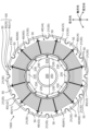
- FIG. 1 is a plan view of a motor according to an embodiment, as viewed from the axial direction.
- FIG. 2 is a plan view of a main portion of the stator as viewed from the axial direction.
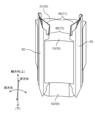
- FIG. 3A is a perspective view of a main part of the stator as viewed from above.
- FIG. 3B is a perspective view of the main part of the stator as viewed from above.
- FIG. 3C is a perspective view of the main part of the stator as viewed from below.
- FIG. 3D is a perspective view of the main part of the stator as viewed from below.
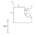
- FIG. 4A is a plan view of the insulating sheet in an unfolded state.
- FIG. 4B is an enlarged view of the area enclosed by the dashed line in FIG. 4A.
- FIG. 5 is a schematic diagram comparing a main part of the insulating sheet according to the embodiment with a main part of an insulating sheet according to a comparative example.
- FIG. 6 is a plan view of a main part of an insulating sheet according to a modified example.
- Fig. 1 is a plan view of a motor according to this embodiment as viewed from the axial direction, in which the illustration and description of connecting wires between coils 40 and external terminals that serve as connection portions to an external power source are omitted.
- the radial direction of motor 1000 is sometimes referred to as the "radial direction”, the outer circumferential direction as the “circumferential direction”, and the direction in which rotating shaft 220 of motor 1000 extends (the direction perpendicular to the paper surface in FIG. 1), in this case the longitudinal direction of rotating shaft 220 as the "axial direction”.
- the center side of motor 1000 is sometimes referred to as the radially inner side, and the outer circumferential side as the radially outer side.
- the side on which split insulator 51 (see FIG. 3A) is arranged on tooth 10 is sometimes referred to as the top or upper side
- the side on which split insulator 52 (see FIG. 3C) is arranged is sometimes referred to as the bottom or lower side.
- the motor 1000 has at least a stator 100 and a rotor 200.
- the motor 1000 has other components, such as bearings that support the rotating shaft 220 and a motor case, but for the sake of convenience, these are not shown or described.
- the motor 1000 is a so-called inner rotor type motor, but is not limited to this and may be an outer rotor type motor.
- the stator 100 has at least a stator core 30, a plurality of coils 40, an insulator 50, and an insulating sheet 60 (see FIG. 2).
- the stator core 30 is composed of an annular yoke 20 and a plurality of teeth 10 (see FIG. 2).
- the teeth 10 are spaced apart at equal angular intervals along the inner circumference (inner surface) of the yoke 20.
- the yoke 20 is an annular member formed by connecting a plurality of split yokes 21 (see FIG. 2) in the circumferential direction. Both the teeth 10 and the split yokes 21 are made of a magnetic material.
- the split yokes 21 on which the teeth 10 are provided may also be referred to as the stator core 30.
- the yoke 20 is formed by connecting multiple split yokes 21 in the circumferential direction.
- the stator core 30 may be formed by integrating the annular yoke 20 with multiple teeth 10.
- the space surrounded by the inner surfaces of the circumferentially adjacent stator cores 30 is configured as a slot 31 (see FIG. 2), and a coil 40 is housed in each of the multiple slots 31.
- the stator 100 is disposed radially outward of the rotor 200 at a fixed distance from the rotor 200.
- the coil 40 is a component made of wound conductor wire with an insulating coating (not shown) formed on its surface.
- the coil 40 is attached to the stator core 30 with an insulating sheet 60 and an insulator 50 sandwiched between them, and is housed in the slot 31. It can also be said that the coil 40 is attached to each of the multiple teeth 10 with the insulating sheet 60 sandwiched between them.
- the coils 40 may be referred to as coils U1 to U4, V1 to V4, and W1 to W4, respectively.
- the insulator 50 is a component made of insulating material attached to the stator core 30, and together with the insulating sheet 60, electrically separates the coil 40 from the stator core 30. Note that in this embodiment, split insulators 51, 52 split into two in the axial direction are used as the insulator 50 (see Figures 2 and 3A to 3D), but it does not have to be split.
- An insulating sheet 60 is provided between the coil 40 and the stator core 30 (see Figure 2 and Figures 3A to 3D).
- the insulating sheet 60 is made by processing insulating paper or a resin insulating sheet into a predetermined shape. The shape of the insulating sheet 60 will be described later.
- the rotor 200 has a rotor core 210, a rotating shaft 220, and a magnet 230.
- the rotor core 210 has a through hole at its axis and is generally cylindrical.
- the rotating shaft 220 is inserted into the through hole of the rotor core 210.
- the magnets 230 are arranged with their north and south poles alternating along the outer periphery of the rotor core 210, facing the stator 100.
- the coils U1 to U4, V1 to V4, and W1 to W4 are connected in series. Three-phase currents of U, V, and W phases, which have a phase difference of 120° electrical angle from each other, are supplied to the coils U1 to U4, V1 to V4, and W1 to W4, respectively, to excite them and generate a rotating magnetic field in the stator 100.
- This rotating magnetic field interacts with the magnetic field generated by the magnet 230 provided in the rotor 200, generating a torque in the rotor 200, and the rotating shaft 220 rotates while being supported by bearings (not shown).
- FIG. 2 shows a plan view of the main parts of the stator as viewed from the axial direction.
- FIGS. 3A and 3B show perspective views of the main parts of the stator as viewed from above.
- FIGS. 3C and 3D show perspective views of the main parts of the stator as viewed from below.
- FIG. 4A shows a plan view of the insulating sheet in an unfolded state.
- FIG. 4B shows an enlarged view of the part surrounded by the dashed line in FIG. 4A.
- the coil 40 is shown by a dashed line to make it easier to understand the structure of the stator core 30 and the insulating sheet 60.
- the coil 40 is not shown in FIGS. 3A and 3B.
- the split insulator 51 is not shown in FIG. 3B.
- the split insulator 52 is not shown in FIG. 3D.
- the insulating sheet 60 is folded and accommodated inside the slot 31.
- the insulating sheet 60 covers the inner surface of the stator core 30, specifically, the circumferential side surfaces of the teeth 10 and the radial inner surface of the split yoke 21.
- the coil 40 wound around the tooth 10 is accommodated inside the space (slot 31) surrounded by the insulating sheet 60.
- the insulating sheet 60 electrically insulates the coil 40 from the stator core 30.
- two coils 40 are housed adjacent to each other, each partially in one slot 31.
- the insulating sheet 60 also provides electrical insulation between adjacent coils 40 inside the slot 31.
- the split insulators 51 and 52 sandwich the insulating sheet 60 and each cover the axial end surface of the stator core 30.
- the split insulator 51 has a coil winding portion 51a, a flange portion 51b located on the radially outer side, and a flange portion 51c located on the radially inner side.
- grooves 51b1 and 51c1 are formed in the flange portions 51b and 51c, respectively.
- the grooves 51b1 and 51c1 are connected to form a groove portion.
- the third to seventh sides 63, 64, 65, 66, and 67 included in one cutout 70 of the insulating sheet 60 are each sandwiched in the groove portion connected from the groove 51b1 to the groove 51c1.
- the split insulator 52 has a coil winding portion 52a, a flange portion 52b located on the radially outer side, and a flange portion 52c located on the radially inner side.
- grooves 52b1 and 52c1 are formed in the flange portions 52b and 52c, respectively.
- the grooves 52b1 and 52c1 are connected to form a groove portion.
- the third to seventh sides 63, 64, 65, 66, and 67 included in the other notch 70 of the insulating sheet 60 are each sandwiched in the groove portion connected from the groove 52b1 to the groove 52c1.
- the insulating sheet 60 is sandwiched between a groove portion that connects groove 51b1 to groove 51c1 in split insulator 51 and a groove portion that connects groove 52b1 to groove 52c1 in split insulator 52. In this way, the position of the insulating sheet 60 is fixed relative to the split insulators 51 and 52.
- the coil 40 is attached to the stator core 30 in contact with the surfaces of the coil winding portions 51a, 52a of the split insulators 51, 52.
- the insulating sheet 60 in an unfolded state is a sheet material that is H-shaped in plan view.
- a notch 70 is formed toward the inside (inner side) of the insulating sheet 60 on each of two opposing sides (hereinafter referred to as first sides 61) of the sheet that is rectangular in plan view.
- first sides 61 two opposing sides
- the second side 62 of the insulating sheet 60 that is perpendicular to the first side 61 is parallel to the axial direction.
- orthogonal or parallel means orthogonal or parallel including the manufacturing tolerances and assembly tolerances of the components that make up motor 1000, and does not mean that the objects being compared are orthogonal or parallel in the strict sense.
- the notch 70 of the insulating sheet 60 includes a third side 63, a fourth side 64, and a first corner portion 71.
- the third side 63 is parallel to the first side 61.
- the fourth side 64 is continuous with the first side 61 and parallel to the second side 62.
- the first angle ⁇ 1 may be any angle less than or equal to 90 degrees ( ⁇ 1 ⁇ 90).
- the first corner portion 71 is provided at the intersection of the third side 63 and the fourth side 64.
- the second angle ⁇ 2 is not limited to 45 degrees, and may be any angle greater than 0 degrees and smaller than the first angle ⁇ 1 (0 ⁇ ⁇ 2 ⁇ ⁇ 1).
- the notch 70 of the insulating sheet 60 includes a third side 63, a seventh side 67, and a second corner portion 72.
- the fourth angle ⁇ 4 may be any angle less than or equal to 90 degrees ( ⁇ 4 ⁇ 90).
- the second corner portion 72 is provided at the intersection of the third side 63 and the seventh side 67.
- the third angle ⁇ 3 is not limited to 45 degrees, and may be any angle greater than 0 degrees and smaller than the fourth angle ⁇ 4 (0 ⁇ ⁇ 3 ⁇ ⁇ 4).
- a location 71a where one end of the third side 63 meets one end of the fifth side 65 may be referred to as a first portion 71a.
- a location 71b where the other end of the fifth side 65 meets one end of the fourth side 64 may be referred to as a second portion 71b.
- a location 71c where the other end of the fourth side 64 meets one end of the first side 61 may be referred to as a third portion 71c.
- the location 72a where the other end of the third side 63 meets one end of the sixth side 66 may be referred to as the fourth portion 72a.
- the location 72b where the other end of the sixth side 66 meets one end of the seventh side 67 may be referred to as the fifth portion 72b.
- the location 72c where the other end of the seventh side 67 meets one end of the first side 61 may be referred to as the sixth portion 72c.
- the notch 70 i.e., the third side 63, the fourth side 64, the seventh side 67, the first corner portion 71, and the second corner portion 72, protrude from the axial end face of the stator core 30 and are disposed outside the slot 31.
- the first corner portion 71 of the insulating sheet 60 is disposed radially outward in the stator 100.
- the second corner portion 72 of the insulating sheet 60 is disposed on the side closer to the tip of the stator core 30, i.e., on the radially inward side in the stator 100.
- the insulating sheet 60 has an asymmetric shape with respect to the center line O1-O2 extending in the axial direction. This is because the shape of the slot 31 differs between the radially inner and outer sides as shown in FIG. 2. In other words, the asymmetry of the shape of the insulating sheet 60 with respect to the center line O1-O2 extending in the axial direction can be changed as appropriate depending on the shape of the slot 31. In other words, the shape of the insulating sheet 60 may be symmetric with respect to the center line O1-O2.
- the insulating sheet 60 protruding outside the slot 31 may be further folded to cover the axial end face of the coil 40.
- the insulating sheet 60 As described above, the insulating sheet 60 according to this embodiment is attached to the stator core 30 of the motor 1000 .
- the insulating sheet 60 is a sheet material that is H-shaped in plan view, with inward-facing notches 70 formed on each of the two opposing first sides 61.
- the notch 70 has a first corner portion 71 and a second corner portion 72.
- the first corner portion 71 is formed at the intersection of the third side 63 and the fourth side 64.
- the third side 63 is parallel to the first side 61 and is located more inward than the first side 61.
- the fourth side 64 is inclined at a first angle ⁇ 1 with respect to the third side 63.
- the first corner portion 71 has a fifth side 65 that is inclined at a second angle ⁇ 2 of less than 90 degrees relative to the third side 63 in a plan view.
- the stator 100 has at least a stator core 30, slots 31, coils 40, and an insulating sheet 60.
- the stator core 30 has an annular yoke 20 and a number of teeth 10 spaced apart at equal angular intervals on the inner surface of the yoke 20.
- the slots 31 are spaces surrounded by the inner surfaces of adjacent stator cores 30.
- the coils 40 are attached to each of the multiple teeth 10 with the insulating sheet 60 sandwiched between them.
- the insulating sheet 60 is accommodated in the slot 31 in a folded state.
- the notch 70 in the insulating sheet 60 protrudes from the axial end face of the stator core 30 and is positioned outside the slot 31.
- the insulation distance (creepage distance) between the axial end face of the stator core 30 and the portion of the coil 40 that abuts against the fifth side 65 (edge) of the first corner portion is constant.
- FIG. 5 shows a schematic diagram comparing the main parts of the insulating sheet according to the embodiment with the main parts of the insulating sheet according to the comparative example.
- the diagram on the left side of FIG. 5 shows the insulating sheet 60 of the embodiment, and the diagram on the right side shows the insulating sheet 80 according to the comparative example.
- the insulating sheet 80 corresponds to the thin insulating material shown in Patent Document 1.
- the coil 40 is wound around the stator core 30, sandwiched between the insulating sheet 60 and the split insulator 51 or split insulator 52.
- the insulation distance between the coil 40 and the stator core 30 corresponds to the boundary between the insulating sheet 60 and the coil 40 exposed from the insulating sheet 60, i.e., the distance between the fifth side 65 of the insulating sheet 60 and the axial end face of the stator core 30.
- This distance i.e., the insulation distance, is shown by line segments A1-A2, B1-B2, and C1-C2 on the left side of Figure 5.
- the length of the line segment B1-B2 corresponds to the sum of the length of the line segment drawn from point B1 located on the extension of the fourth side 64 parallel to the third side 63 to the fifth side 65, and the length of the line segment drawn from the fifth side 65 parallel to the fourth side 64 to the axial end face of the stator core 30.
- the length of the line segment C1-C2 corresponds to the sum of the length of the line segment drawn from C1, located at the extension of the fourth side 64, parallel to the third side 63 to the fifth side 65, and the length of the line segment drawn from the fifth side 65 parallel to the fourth side 64 to the axial end face of the stator core 30.
- the fifth side 65 constituting the first corner portion 71 is inclined with respect to the third side 63 at a second angle ⁇ 2 ( ⁇ 2 ⁇ 90) that is smaller than the first angle ⁇ 1. Therefore, the aforementioned insulation distance at the first corner portion 71 is constant.
- the third side 83 and the fourth side 84 intersect perpendicularly, so that the first corner portion 91 forms a right angle.
- the first side 81 of the insulating sheet 80 corresponds to the first side 61 of the insulating sheet 60
- the second side 82 of the insulating sheet 80 corresponds to the second side 62 of the insulating sheet 60.
- the insulation distance between the coil 40 and the stator core 30 is the length of the line segment D1-D2 shown on the right side of FIG. 5.
- the axial height does not change continuously, as in the first corner portion 71 of the insulating sheet 60 shown on the left side of FIG. 5.
- the length of the line segment D1-D2 is longer than the length of the line segment A1-A2 by ⁇ H.
- a similar condition occurs in the notch 90 provided on the other side in the axial direction.
- the axial length of the stator 100 becomes longer by 2 ⁇ H compared to the case shown in this embodiment. This increases the axial size of the stator 100, and therefore the motor 1000, which is an obstacle to miniaturization of the stator 100 and the motor 1000.
- the size of the stator 100 and the motor 1000 can be prevented from increasing in the axial direction, and the motor 1000 can be made smaller.
- the insulation distance between the coil 40 and the stator core 30 can be guaranteed, so that the reliability of the motor 1000 during operation can be prevented from decreasing.
- the sixth side 66 constituting the second corner portion 72 of the insulating sheet 60 also forms a third angle ⁇ 3 with respect to the third side 63.
- the insulating sheet 60 can prevent the size of the stator 100, and therefore the motor 1000, from increasing in the axial direction while ensuring the insulation distance between the coil 40 and the stator core 30 even at the second corner portion 72.
- the fifth side 65 constituting the first corner portion 71 is preferably a straight line in a plan view. In this way, as described above, it is possible to ensure that the insulation distance between the coil 40 and the stator core 30 is equal to or greater than a predetermined value throughout the entire first corner portion 71. For the same reason, the sixth side 66 constituting the second corner portion 72 is preferably a straight line in a plan view.
- the second angle ⁇ 2 and the third angle ⁇ 3 are not limited to 45 degrees.
- the preferred ranges for the second angle ⁇ 2 and the third angle ⁇ 3 are 30 degrees or more and 60 degrees or less (30 ⁇ 2 ⁇ 60, 30 ⁇ 3 ⁇ 60).
- the insulation distance becomes shorter, so it becomes necessary to maintain the insulation distance by increasing the length of the insulating sheet 60 and increasing the height of the insulator 50 (split insulators 51, 52). Therefore, the total axial length of the assembly part of the stator 100, that is, the part where the insulator 50, the stator core 30, and the insulating sheet 60 are integrated, becomes longer, and as a result, the motor 1000 becomes larger.
- the second angle ⁇ 2 and the third angle ⁇ 3 are set to 30 degrees or more and 60 degrees or less, respectively, it is possible to ensure the insulation distance between the coil 40 and the stator core 30.
- the increase in the length of the insulating sheet 60 and the height of the insulator 50 can be suppressed, and the motor 1000 can be made smaller.
- the second angle ⁇ 2 is 45 degrees.
- the insulation distance between the coil 40 and the stator core 30 can be made constant and maximized throughout the entire first corner portion 71.
- the third angle ⁇ 3 is 45 degrees at the second corner portion 72.
- the second angle ⁇ 2 needs only to be smaller than the first angle ⁇ 1. In this way, the axial height of the first corner portion 71 can be reduced while still ensuring the aforementioned insulation distance.
- the third angle ⁇ 3 needs only to be smaller than the fourth angle ⁇ 4.
- the motor 1000 includes at least a stator 100 and a rotor 200 arranged at a predetermined radial distance from the stator 100.
- the insulation distance between the coil 40 and the stator core 30 can be guaranteed while preventing the size of the stator 100, and therefore the motor 1000, from increasing in the axial direction. This allows the motor 1000 to be made smaller and its reliability during operation to be improved.
- Fig. 6 is a plan view of a main part of an insulating sheet according to a modified example.
- the same reference numerals are used for the same parts as those in the first embodiment, and detailed explanations thereof will be omitted.
- the insulating sheet 60 of this modified example shown in FIG. 6 differs from the insulating sheet 60 of the embodiment shown in FIGS. 4A and 4B in that the fifth side 65a constituting the first corner portion 71 is rounded into an arc shape having a radius of curvature (first radius of curvature) R.
- the insulating sheet 60 may be configured in this manner, and the same effects as those achieved by the configuration shown in the embodiment can be achieved. In other words, the insulation distance between the coil 40 and the stator core 30 can be ensured, while preventing the size of the stator 100, and therefore the motor 1000, from increasing in the axial direction. This allows the motor 1000 to be made more compact, and increases its reliability during operation.
- the fifth side 65a may be an elliptical arc shape.
- the sixth side 66 may be in the shape of a circular arc or an elliptical arc having a radius of curvature R.
- the stator 100 in this specification is configured to use an insulating sheet 60 so that the insulation distance between the axial end face of the stator core 30 and the portion of the coil 40 that abuts against the edge (fifth side 65 or fifth side 65a) of the first corner portion 71 is constant.
- stator 100 is configured with an insulating sheet 60 so that the insulation distance between the axial end face of the stator core 30 and the portion of the coil 40 that abuts against the edge (sixth side 66) of the second corner portion 72 is constant.
- the motor 1000 is a three-phase AC motor
- the present invention is not particularly limited to this.
- the motor 1000 may be a DC motor.
- the number of poles of the motor 1000 (the total number of poles of the magnets 230), the number of slots 31, and further the number of phases of the motor 1000 may be appropriately changed depending on the application of the motor 1000, etc.
- the stator core 30 and rotor core 210 are each made of a magnetic material, and the materials are selected appropriately according to the specifications of the motor 1000.
- the insulating sheet may be an insulating sheet formed by appropriately combining partial configurations of the insulating sheet according to the embodiments and modified examples.
- the materials, numerical values, etc. described in the embodiments are merely preferred examples, and are not limited thereto.
- the insulating sheet disclosed herein is useful because it can prevent the stator, and therefore the motor, from increasing in size in the axial direction while maintaining the insulation distance between the coil and the stator core.
Landscapes
- Engineering & Computer Science (AREA)
- Power Engineering (AREA)
- Insulation, Fastening Of Motor, Generator Windings (AREA)
- Iron Core Of Rotating Electric Machines (AREA)
Abstract
モータの固定子鉄心に取り付けられる絶縁シートは、対向する2つの第1辺のそれぞれに、内側に向かう切り欠きが形成されてなる、平面視でH字形状のシート材である。切り欠きは、第1コーナー部と第2コーナー部とを有している。第1コーナー部は、第3辺と第4辺との交差部分に形成されている。第3辺は、第1辺と平行でかつ第1辺よりも内側に位置している。第4辺は、第3辺に対して第1の角度で傾斜している。第1コーナー部は、平面視で、第3辺に対して、90度未満の第2の角度で傾斜した第5辺を有している。
Description
本開示は、絶縁シート及びそれを備えた固定子、モータに関する。
従来、サーボモータ等の産業用モータでは、固定子の内部でコイルと固定子鉄心とを絶縁するために、絶縁シートを用いている。固定子鉄心に設けられたスロットの内面を覆うように絶縁シートが収容され、さらに、絶縁シートの内側にコイルが収容される。
一方、固定子鉄心の軸方向端部は、通常、絶縁シートで覆われていないため、インシュレータを別途準備して、当該端部に装着する必要があった。
特許文献1には、インシュレータを無くして、部品点数を減らすために、V字形状の折り曲げ部を設けた絶縁薄状物をコイルと固定子鉄心との間に介在させる構成が開示されている。また、この構成によれば、コイルと固定子鉄心との間に一定距離を確保できる。つまり、コイルと固定子鉄心との間の絶縁距離を一定にできる。
しかし、特許文献1に開示された従来の構成では、コイルと固定子鉄心の軸方向端面との間の絶縁距離を確保するには、V字形状の折り曲げ部を軸方向に高く設ける必要がある。また、折り曲げ部に連続するコイル包囲部の軸方向の高さも、同時に高くする必要がある。
しかし、絶縁薄状物をこのように構成すると、固定子、ひいては、モータの軸方向の長さが長くなってしまう。つまり、モータの小型化を阻害する要因となる。
本開示はかかる点に鑑みてなされたもので、その目的は、コイルと固定子鉄心との間の絶縁距離を担保しつつ、固定子のサイズが軸方向に大きくなるのを抑制できる絶縁シート及びそれを備えた固定子、モータを提供することにある。
上記目的を達成するため、本開示に係る絶縁シートは、モータの固定子に取り付けられる絶縁シートである。絶縁シートは、対向する2つの第1辺のそれぞれに、内側に向かう切り欠きが形成されてなる、平面視でH字形状のシート材である。切り欠きは、第1コーナー部と第2コーナー部とを有している。第1コーナー部は、第1辺と平行でかつ第1辺よりも内側に位置する第3辺と第1辺に連続して形成されているか、または、第1辺と平行でかつ第1辺よりも内側に位置する第3辺と第1辺に連続し、かつ第3辺に対して第1の角度で傾斜した第4辺との交差部分に形成されている。そして、少なくとも第1コーナー部は、第1曲率半径を有するように丸められているか、または、平面視で、第3辺に対して、90度未満の第2の角度で傾斜した第5辺を有したことを特徴とする。
本開示に係る固定子は、絶縁シートが取り付けられたモータの固定子である。固定子は、固定子鉄心と、スロットと、コイルと、を少なくとも有する。固定子鉄心は、環状のヨークと、ヨークの内面に等角度間隔で互いに間隔をあけて設けられた複数のティースと、を有する。スロットは、隣り合う固定子鉄心の内面で囲まれる空間である。コイルは、絶縁シートを挟んで複数のティースのそれぞれに装着されている。モータの回転軸の長手方向を軸方向とするとき、絶縁シートは、折り曲げられた状態でスロットに収容されている。切り欠きは、固定子鉄心の軸方向の端面から突出して、スロットの外部に配置されている。モータの固定子は、固定子鉄心の軸方向の端面と、前記コイルのうち第1コーナー部の縁辺と当接する部分との絶縁距離は、一定であることを特徴とする。
本開示に係るモータは、固定子と、固定子と所定の間隔をあけて設けられた回転子と、を少なくとも備えたことを特徴とする。
本開示によれば、コイルと固定子鉄心との間の絶縁距離を担保しつつ、固定子,ひいては、モータのサイズが軸方向に大きくなるのを比較的抑制できる。
以下、本開示の実施形態を図面に基づいて詳細に説明する。以下の好ましい実施形態の説明は、本質的に例示に過ぎず、本開示、その適用物或いはその用途を制限することを意図するものでは全くない。
(実施形態)
[モータの構成]
図1は、本実施形態に係るモータを軸方向から見た平面図を示す。なお、図1において、コイル40間の渡し線や外部電源との接続部となる外部端子については図示及び説明を省略している。
[モータの構成]
図1は、本実施形態に係るモータを軸方向から見た平面図を示す。なお、図1において、コイル40間の渡し線や外部電源との接続部となる外部端子については図示及び説明を省略している。
また、以降の説明において、モータ1000の半径方向を「径方向」と、外周方向を「周方向」と、モータ1000の回転軸220の延びる方向(図1における紙面と垂直な方向)、この場合は、回転軸220の長手方向を「軸方向」とそれぞれ呼ぶことがある。また、径方向において、モータ1000の中心側を径方向内側と、外周側を径方向外側と呼ぶことがある。軸方向において、ティース10に分割インシュレータ51(図3A参照)が配置された側を、上または上方と呼び、分割インシュレータ52(図3C参照)が配置された側を、下または下方と呼ぶことがある。
モータ1000は、固定子100と、回転子200と、を少なくとも備えている。なお、モータ1000は、これら以外の構成部品、例えば、回転軸220を軸支する軸受やモータケース等の部品を有しているが、説明の便宜上、その図示及び説明を省略する。モータ1000は、いわゆるインナーロータ型のモータであるが特にこれに限定されず、アウターロータ型のモータであってもよい。
固定子100は、固定子鉄心30と、複数のコイル40と、インシュレータ50と、絶縁シート60(図2参照)と、を少なくとも有している。固定子鉄心30は、円環状のヨーク20と、複数のティース10(図2参照)とで構成されている。複数のティース10は、ヨーク20の内周(内面)に沿って等角度間隔で互いに間隔をあけて設けられている。ヨーク20は、複数の分割ヨーク21(図2参照)を周方向に接続してなる円環状の部材である。ティース10及び分割ヨーク21ともに、磁性体材料からなる。なお、以降の説明において、ティース10が設けられた分割ヨーク21も、固定子鉄心30と呼ぶことがある。
なお、本実施形態では、複数の分割ヨーク21を周方向に接続してヨーク20を構成した。しかしながら特にこれに限られず、円環状のヨーク20と複数のティース10とが一体化されて、固定子鉄心30を構成していてもよい。
また、周方向に隣り合う固定子鉄心30の内面で囲まれる空間がスロット31(図2参照)として構成され、複数のスロット31内にそれぞれコイル40が収容される。固定子100は、回転子200の径方向外側に、回転子200と一定の間隔をあけて配置されている。
コイル40は、表面に絶縁皮膜(図示せず)が形成された導線が巻回されてなる部品である。コイル40は、絶縁シート60とインシュレータ50とを挟んで固定子鉄心30に装着されて、スロット31内に収容されている。なお、コイル40は、絶縁シート60を挟んで複数のティース10のそれぞれに装着されているとも言える。また、コイル40に流れる電流の位相に応じて、コイル40をコイルU1~U4,V1~V4,W1~W4とそれぞれ呼ぶことがある。
インシュレータ50は、固定子鉄心30に装着された絶縁材料からなる部品であり、絶縁シート60と併せて、コイル40と固定子鉄心30とを電気的に分離している。なお、本実施形態では、インシュレータ50として、軸方向に二分割された分割インシュレータ51,52を用いているが(図2、図3A~3D参照)、分割されていなくてもよい。
コイル40と固定子鉄心30との間には絶縁シート60が設けられている(図2、図3A~3D参照)。絶縁シート60は、絶縁紙または樹脂製の絶縁シートを所定の形状に加工してなる。絶縁シート60の形状等については後で述べる。
回転子200は、回転子鉄心210と、回転軸220と、磁石230と、を有している。回転子鉄心210は、軸心に貫通孔を有し、略円筒状である。回転軸220は、回転子鉄心210の貫通孔に挿通されている。磁石230は、固定子100に対向してN極、S極が回転子鉄心210の外周方向に沿って交互に配置されている。
コイルU1~U4,V1~V4,W1~W4はそれぞれ直列に接続されている。そして、互いに電気角で120°の位相差を有するU,V,W相の3相の電流がそれぞれコイルU1~U4,V1~V4,W1~W4に供給されて励磁され、固定子100に回転磁界が発生する。この回転磁界と、回転子200に設けられた磁石230が発生する磁界とが相互作用して、回転子200にトルクが発生し、回転軸220が軸受(図示せず)に支持されて回転する。
[固定子の要部及び絶縁シートの構成]
図2は、固定子の要部を軸方向から見た平面図を示す。図3A,3Bは、固定子の要部を上方から見た斜視図を示す。図3C,3Dは、固定子の要部を下方から見た斜視図をそれぞれ示す。図4Aは、展開された状態の絶縁シートの平面図を示す。図4Bは、図4Aにおける破線で囲まれた部分の拡大図をそれぞれ示す。なお、固定子鉄心30や絶縁シート60の構造を分かりやすくするために、図2において、コイル40を破線で示している。また、図3A~3Bにおいて、コイル40の図示を省略している。また、図3Bにおいて、分割インシュレータ51の図示を省略している。図3Dにおいて、分割インシュレータ52の図示を省略している。
図2は、固定子の要部を軸方向から見た平面図を示す。図3A,3Bは、固定子の要部を上方から見た斜視図を示す。図3C,3Dは、固定子の要部を下方から見た斜視図をそれぞれ示す。図4Aは、展開された状態の絶縁シートの平面図を示す。図4Bは、図4Aにおける破線で囲まれた部分の拡大図をそれぞれ示す。なお、固定子鉄心30や絶縁シート60の構造を分かりやすくするために、図2において、コイル40を破線で示している。また、図3A~3Bにおいて、コイル40の図示を省略している。また、図3Bにおいて、分割インシュレータ51の図示を省略している。図3Dにおいて、分割インシュレータ52の図示を省略している。
図2に示すように、絶縁シート60は、スロット31の内部に折り曲げられて収容されている。絶縁シート60は、固定子鉄心30の内面、具体的には、ティース10の周方向側面と分割ヨーク21の径方向の内面とを覆っている。また、絶縁シート60で囲まれた空間(スロット31)の内部に、ティース10に巻回されたコイル40が収容される。つまり、絶縁シート60は、コイル40と固定子鉄心30とを電気的に絶縁している。
また、図2から明らかなように、1つのスロット31に対して、2つのコイル40が、それぞれ一部ずつ、かつ隣接して収容されている。絶縁シート60は、スロット31の内部で隣接するコイル40の間も電気的に絶縁している。
また、分割インシュレータ51,52は、絶縁シート60を挟み込んで、固定子鉄心30の軸方向端面をそれぞれ覆っている。図3A,3Bに示すように、分割インシュレータ51は、コイル巻回部51aと、径方向外側に位置するフランジ部51bと、径方向内側に位置するフランジ部51cと、を有している。図3Aに示すように、フランジ部51b,51cのそれぞれに溝51b1,51c1が形成されている。図示しないが、溝51b1と溝51c1とは連なって溝部を構成している。溝51b1から溝51c1に連なる溝部に絶縁シート60の一方の切り欠き70に含まれる第3~7辺63,64,65,66,67とがそれぞれ挟み込まれる。
また、図3C,3Dに示すように、分割インシュレータ52は、コイル巻回部52aと、径方向外側に位置するフランジ部52bと、径方向内側に位置するフランジ部52cと、を有している。図3Cに示すように、フランジ部52b,52cのそれぞれに溝52b1,52c1が形成されている。図示しないが、溝52b1と溝52c1とは連なって溝部を構成している。溝52b1から溝52c1に連なる溝部に絶縁シート60の他方の切り欠き70に含まれる第3~7辺63,64,65,66,67とがそれぞれ挟み込まれる。
つまり、図3A,3Bに示すように、絶縁シート60は、分割インシュレータ51に設けられた溝51b1から溝51c1に連なる溝部と、分割インシュレータ52に設けられた溝52b1から溝52c1に連なる溝部とに挟み込まれている。このようにすることで、分割インシュレータ51,52に対して、絶縁シート60の位置が固定される。
コイル40は、分割インシュレータ51,52のコイル巻回部51a,52aの表面に接して固定子鉄心30に装着されている。
図4Aに示すように、展開された状態の絶縁シート60は、平面視でH字形状のシート材である。つまり、平面視で四角形のシートの対向する2辺(以下、第1辺61と言う)のそれぞれに、絶縁シート60の内部(内側)に向かう切り欠き70が形成されている。なお、スロット31に収容された状態で、絶縁シート60の第1辺61と直交する第2辺62が、軸方向と平行になっている。
なお、本願明細書において、「直交」または「平行」とは、モータ1000を構成する各部品の製造公差や組立公差を含んで直交または平行と言う意味であり、比較対象同士が厳密な意味で直交または平行であることまでを意味するものではない。
図4A,4Bに示すように、絶縁シート60の切り欠き70は、第3辺63と第4辺64と第1コーナー部71とを含んでいる。絶縁シート60が展開された状態で、第3辺63は第1辺61と平行である。第4辺64は、第1辺61に連続し、かつ第2辺62と平行である。つまり、第4辺64は、第3辺63に対して第1の角度θ1(=90度)をなしている。なお、第1の角度θ1は、90度以下であればよい(θ1≦90)。
また、第1コーナー部71は、第3辺63と第4辺64との交差部分に設けられている。本実施形態では、第1コーナー部71は、第3辺63の一端と第4辺64の一端とにそれぞれ接続され、第3辺63に対して第2の角度θ2(=45度)をなす直線状の第5辺65として構成されている。なお、第2の角度θ2は、45度に限定されず、0度よりも大きく第1の角度θ1よりも小さければよい(0<θ2<θ1)。
また、図4A,4Bに示すように、絶縁シート60の切り欠き70は、第3辺63と第7辺67と第2コーナー部72とを含んでいる。絶縁シート60が展開された状態で、第7辺67は、第1辺61に連続し、かつ第3辺63に対して第4の角度θ4(=90度)をなしている。なお、第4の角度θ4は、90度以下であればよい(θ4≦90)。
また、第2コーナー部72は、第3辺63と第7辺67との交差部分に設けられている。本実施形態では、第2コーナー部72は、第3辺63の他端と第7辺67の一端とにそれぞれ接続され、第3辺63に対して第3の角度θ3(=45度)をなす直線状の第6辺66として構成されている。なお、第3の角度θ3は、45度に限定されず、0度よりも大きく第4の角度θ4よりも小さければよい(0<θ3<θ4)。
図4A,4Bに示すように、第1コーナー部71において、第3辺63の一端と第5辺65の一端とが接する箇所71aを第1部分71aと呼ぶことがある。第5辺65の他端と第4辺64の一端とが接する箇所71bを第2部分71bと呼ぶことがある。また、第4辺64の他端と第1辺61の一端とが接する箇所71cを第3部分71cと呼ぶことがある。
第2コーナー部72において、第3辺63の他端と第6辺66の一端とが接する箇所72aを第4部分72aと呼ぶことがある。第6辺66の他端と第7辺67の一端とが接する箇所72bを第5部分72bと呼ぶことがある。また、第7辺67の他端と第1辺61の一端とが接する箇所72cを第6部分72cと呼ぶことがある。
図3A~3Dに示すように、絶縁シート60がスロット31に収容された状態で、切り欠き70、つまり、第3辺63と第4辺64と第7辺67と第1コーナー部71と第2コーナー部72とは、固定子鉄心30の軸方向の端面から突出して、スロット31の外部に配置されている。また、この状態で、絶縁シート60の第1コーナー部71が、固定子100において、径方向外側に配置される。絶縁シート60の第2コーナー部72が、固定子鉄心30の先端に近い側、つまり、固定子100において、径方向内側に配置される。
なお、図4Aに示すように、絶縁シート60は、軸方向に延びる中心線O1-O2に関して非対称な形状となっている。これは、図2に示すように、スロット31の形状が径方向内側と外側とで異なっているためである。つまり、軸方向に延びる中心線O1-O2に関する絶縁シート60の形状の非対称性は、スロット31の形状に応じて適宜変更されうる。つまり、中心線O1-O2に関して、絶縁シート60の形状が対称であってもよい。
なお、スロット31の外部に突出した絶縁シート60がさらに折り曲げられて、コイル40の軸方向端面を覆っていてもよい。
[効果等]
以上説明したように、本実施形態に係る絶縁シート60は、モータ1000の固定子鉄心30に取り付けられる。
以上説明したように、本実施形態に係る絶縁シート60は、モータ1000の固定子鉄心30に取り付けられる。
絶縁シート60は、対向する2つの第1辺61のそれぞれに、内側に向かう切り欠き70が形成されてなる、平面視でH字形状のシート材である。
切り欠き70は、第1コーナー部71と第2コーナー部72とを有している。第1コーナー部71は、第3辺63と第4辺64との交差部分に形成されている。第3辺63は、第1辺61と平行でかつ第1辺61よりも内側に位置している。第4辺64は、第3辺63に対して第1の角度θ1で傾斜している。
第1コーナー部71は、平面視で、第3辺63に対して、90度未満の第2の角度θ2で傾斜した第5辺65を有している。
また、本実施形態に係る固定子100は、固定子鉄心30とスロット31とコイル40と絶縁シート60とを少なくとも有している。固定子鉄心30は、環状のヨーク20と、ヨーク20の内面に等角度間隔で互いに間隔をあけて設けられた複数のティース10と、を有している。スロット31は、隣り合う固定子鉄心30の内面で囲まれる空間である。コイル40は、絶縁シート60を挟んで複数のティース10のそれぞれに装着されている。
絶縁シート60は、折り曲げられた状態でスロット31に収容されている。絶縁シート60の切り欠き70は、固定子鉄心30の軸方向端面から突出して、スロット31の外部に配置される。
固定子鉄心30の軸方向端面と、コイル40のうち第1コーナー部の第5辺65(縁辺)と当接する部分との絶縁距離(沿面距離)は、一定である。
本実施形態によれば、コイル40と固定子鉄心30との間の絶縁距離を担保しつつ、固定子100,ひいては、モータ1000のサイズが軸方向に大きくなるのを抑制できる。このことについてさらに説明する。
図5は、実施形態に係る絶縁シートの要部と比較例に係る絶縁シートの要部とを比較した模式図を示している。図5の左側の図が、本実施形態の絶縁シート60であり、右側の図が比較例に係る絶縁シート80である。絶縁シート80は、特許文献1に示した絶縁薄状物に対応している。
絶縁シート60と分割インシュレータ51または分割インシュレータ52とを挟んで固定子鉄心30にコイル40が巻回されている。
絶縁シート60の第1コーナー部71では、コイル40と固定子鉄心30との間の絶縁距離は、絶縁シート60と絶縁シート60から露出したコイル40との境界、つまり、絶縁シート60の第5辺65と固定子鉄心30の軸方向端面との間の距離に相当する。この距離、つまり、当該絶縁距離は、図5の左側では、線分A1-A2,B1-B2,C1-C2で示されている。なお、線分B1-B2の長さは、第4辺64の延長部分に位置する点B1から、第3辺63と平行に引いて第5辺65に達するまでの線分の長さと、第5辺65から第4辺64と平行に引いて固定子鉄心30の軸方向端面に達する線分の長さとの和に相当する。また線分C1-C2の長さは、第4辺64の延長部分に位置するC1から、第3辺63と平行に引いて第5辺65に達するまでの線分の長さと、第5辺65から第4辺64と平行に引いて固定子鉄心30の軸方向端面に達する線分の長さとの和に相当する。
図5の左側に示すように、本実施形態の絶縁シート60は、第1コーナー部71を構成する第5辺65が第3辺63に対して、第1の角度θ1よりも小さい第2の角度θ2(θ2<90)で傾斜して設けられている。このため、第1コーナー部71における前述した絶縁距離は、一定となっている。
一方、図5の右側に示す比較例の絶縁シート80の切り欠き90では、第3辺83と第4辺84とが直交するように交差しているため、第1コーナー部91は、直角となっている。なお、絶縁シート80の第1辺81は、絶縁シート60の第1辺61に対応し、絶縁シート80の第2辺82は、絶縁シート60の第2辺62に対応している。
このため、第1コーナー部91において、コイル40と固定子鉄心30との間の絶縁距離は、図5の右側に示す線分D1-D2の長さとなる。ただし、図5の右側に示す絶縁シート80では、図5の左側に示す絶縁シート60の第1コーナー部71のように、軸方向の高さが連続的に変化していない。このため、必要な絶縁距離を確保するために、線分D1-D2の長さは、線分A1-A2の長さに比べてΔHだけ長くなる。また、図示しないが、軸方向の他方に設けられた切り欠き90においても同様の状態が生じている。
つまり、絶縁シート80をスロット31に取り付けた場合、本実施形態に示す場合に比べて、固定子100の軸方向の長さが、2ΔHだけ長くなる。そのため、固定子100、ひいては、モータ1000の軸方向のサイズが大きくなり、固定子100やモータ1000の小型化を阻害する要因となっていた。
一方、本実施形態によれば、固定子100やモータ1000のサイズが軸方向に大きくなるのを抑制でき、モータ1000を小型化できる。また、コイル40と固定子鉄心30との間の絶縁距離を担保できるため、モータ1000の動作時の信頼性が低下するのを抑制できる。
なお、図4Bに示すように、絶縁シート60の第2コーナー部72を構成する第6辺66も、第3辺63に対して第3の角度θ3をなしている。つまり、絶縁シート60は、第2コーナー部72においても、コイル40と固定子鉄心30との間の絶縁距離を担保しつつ、固定子100,ひいては、モータ1000のサイズが軸方向に大きくなるのを抑制できる。
第1コーナー部71を構成する第5辺65は、平面視で、直線であることが好ましい。このようにすることで、前述したように、第1コーナー部71の全体にわたって、コイル40と固定子鉄心30との間の絶縁距離を所定値以上になるように担保できる。同様の理由から、第2コーナー部72を構成する第6辺66は、平面視で、直線であることが好ましい。
なお、前述したように、第2の角度θ2及び第3の角度θ3は、それぞれ、45度に限定されない。第2の角度θ2及び第3の角度θ3の好ましい範囲は、それぞれ、30度以上、60度以下である(30≦θ2≦60、30≦θ3≦60)。
第2の角度θ2及び第3の角度θ3が45度から大きく、または小さくなるにしたがって、絶縁距離が短くなるので、その分、絶縁シート60の長さを長く、かつインシュレータ50(分割インシュレータ51,52)の高さを高くすることで、絶縁距離を維持することが必要となる。したがって、固定子100の組立部、つまり、インシュレータ50、固定子鉄心30及び絶縁シート60とが一体化した部分の軸方向の全長が長くなり、その結果、モータ1000が大型化する。
そこで、第2の角度θ2及び第3の角度θ3をそれぞれ、30度以上、60度以下とすることにより、コイル40と固定子鉄心30との間の絶縁距離を担保することができる。また、絶縁シート60の長さ及びインシュレータ50の高さの増加を抑制でき、モータ1000を小型化することができる。
また、第2の角度θ2は、45度であることがより好ましい。このようにすることで、前述したように、第1コーナー部71の全体にわたって、コイル40と固定子鉄心30との間の絶縁距離を一定に、かつ最も長くすることができる。同様の理由から、第2コーナー部72において、第3の角度θ3は45度であることがより好ましい。
なお、第1コーナー部71において、第2の角度θ2は、第1の角度θ1よりも小さければよい。このようにすることで、第1コーナー部71の軸方向の高さを小さくしつつ、前述の絶縁距離を担保できる。同様の理由から、第2コーナー部72において、第3の角度θ3は、第4の角度θ4よりも小さければよい。
本実施形態に係るモータ1000は、固定子100と、固定子100と径方向に所定の間隔をあけて設けられた回転子200と、を少なくとも備えている。
本実施形態によれば、コイル40と固定子鉄心30との間の絶縁距離を担保しつつ、固定子100,ひいては、モータ1000のサイズが軸方向に大きくなるのを抑制できる。このことにより、モータ1000の小型化が図れるとともに、動作時の信頼性を高められる。
<変形例>
図6は、変形例に係る絶縁シートの要部の平面図を示す。なお、説明の便宜上、図6において、実施形態1と同様の箇所については同一の符号を付して詳細な説明を省略する。
図6は、変形例に係る絶縁シートの要部の平面図を示す。なお、説明の便宜上、図6において、実施形態1と同様の箇所については同一の符号を付して詳細な説明を省略する。
図6に示す本変形例の絶縁シート60は、第1コーナー部71を構成する第5辺65aが、曲率半径(第1曲率半径)Rを有するように丸められた円弧形状である点で、図4A,4Bに示す実施形態の絶縁シート60と異なる。
絶縁シート60をこのように構成してもよく、実施形態に示す構成が奏するのと同様の効果を奏することができる。つまり、コイル40と固定子鉄心30との間の絶縁距離を担保しつつ、固定子100,ひいては、モータ1000のサイズが軸方向に大きくなるのを抑制できる。このことにより、モータ1000の小型化が図れるとともに、動作時の信頼性を高められる。なお、第5辺65aは楕円弧形状であってもよい。
なお、図示しないが、第2コーナー部72において、第6辺66が曲率半径Rを有する円弧形状あるいは楕円弧形状であってもよい。
本変形例を含めてみれば、本願明細書における固定子100は、絶縁シート60を用いることにより、固定子鉄心30の軸方向端面と、コイル40のうち第1コーナー部71の縁辺(第5辺65または第5辺65a)と当接する部分との絶縁距離が一定となるように構成されている。
同様に、固定子100は、絶縁シート60を用いることにより、固定子鉄心30の軸方向端面と、コイル40のうち第2コーナー部72の縁辺(第6辺66)と当接する部分との絶縁距離が一定となるように構成されている。
(その他の実施形態)
本願明細書では、モータ1000が3相交流モータである例を示したが、特にこれに限定されない。例えば、モータ1000が直流モータであってもよい。また、モータ1000の極数(磁石230のトータルの極数)やスロット31の数、さらに、モータ1000の相数も、モータ1000の用途等に応じて適宜変更されうる。
本願明細書では、モータ1000が3相交流モータである例を示したが、特にこれに限定されない。例えば、モータ1000が直流モータであってもよい。また、モータ1000の極数(磁石230のトータルの極数)やスロット31の数、さらに、モータ1000の相数も、モータ1000の用途等に応じて適宜変更されうる。
また、固定子鉄心30及び回転子鉄心210は、それぞれ磁性体材料からなるが、これらの材質は、モータ1000の仕様に応じて適宜選択される。
以上、本開示の構成を実施形態及び変形例に基づいて説明したが、本開示は上記実施形態及び変形例に限られない。例えば、実施形態及び変形例に係る絶縁シートの部分的な構成を、適宜組み合わせてなる絶縁シートであってもよい。また、実施形態に記載した材料、数値等は好ましいものを例示しているだけであり、それに限定されることはない。さらに、本開示の技術的思想の範囲を逸脱しない範囲で、絶縁シートの構成に適宜変更を加えることは可能である。
本開示の絶縁シートは、コイルと固定子鉄心との間の絶縁距離を担保しつつ、固定子,ひいては、モータのサイズが軸方向に大きくなるのを抑制できるため、有用である。
10 ティース
20 ヨーク
21 分割ヨーク
30 固定子鉄心
31 スロット
40 コイル
50 インシュレータ
51,52 分割インシュレータ
60 絶縁シート
61 第1辺
62 第2辺
63 第3辺
64 第4辺
65 第5辺
65a 第5辺
66 第6辺
67 第7辺
70 切り欠き
71 第1コーナー部
71a 第1部分
71b 第2部分
71c 第3部分
72 第2コーナー部
72a 第4部分
72b 第5部分
72c 第6部分
80 絶縁シート
81 第1辺
82 第2辺
83 第3辺
84 第4辺
90 切り欠き
91 第1コーナー部
100 固定子
200 回転子
210 回転子鉄心
220 回転軸
230 磁石
1000 モータ
θ1~θ4 第1~第4の角度
Claims (7)
- モータの固定子に取り付けられる絶縁シートであって、
前記絶縁シートは、対向する2つの第1辺のそれぞれに、内側に向かう切り欠きが形成されてなる、平面視でH字形状のシート材であり、
前記切り欠きは、第1コーナー部と第2コーナー部とを有しており、
前記第1コーナー部は、
前記第1辺と平行でかつ前記第1辺よりも内側に位置する第3辺と前記第1辺に連続して形成されているか、または、
前記第1辺と平行でかつ前記第1辺よりも内側に位置する第3辺と前記第1辺に連続し、かつ前記第3辺に対して第1の角度で傾斜した第4辺との交差部分に形成されており、
少なくとも前記第1コーナー部は、
第1曲率半径を有するように丸められているか、または、
平面視で、前記第3辺に対して90度未満の第2の角度で傾斜した第5辺を有したことを特徴とする絶縁シート。 - 請求項1に記載の絶縁シートにおいて、
前記第2の角度は、前記第1の角度よりも小さいことを特徴とする絶縁シート。 - 請求項2に記載の絶縁シートにおいて、
前記第2の角度は30度以上、60度以下であることを特徴とする絶縁シート。 - 請求項3に記載の絶縁シートにおいて、
前記第2の角度は45度であることを特徴とする絶縁シート。 - 請求項1に記載の絶縁シートにおいて、
前記第5辺は、平面視で、直線であることを特徴とする絶縁シート。 - 請求項1ないし5のいずれか1項に記載の絶縁シートが取り付けられたモータの固定子であって、
前記固定子は、
環状のヨークと、前記ヨークの内面に等角度間隔で互いに間隔をあけて設けられた複数のティースと、を有する固定子鉄心と、
隣り合う前記固定子鉄心の内面で囲まれる空間であるスロットと、
前記絶縁シートを挟んで前記複数のティースのそれぞれに装着されたコイルと、
を少なくとも有し、
前記モータの回転軸の長手方向を軸方向とするとき、
前記絶縁シートは、折り曲げられた状態で前記スロットに収容されており、
前記切り欠きは、前記固定子鉄心の前記軸方向の端面から突出して、前記スロットの外部に配置されており、
前記固定子鉄心の前記軸方向の端面と、前記コイルのうち前記第1コーナー部の縁辺と当接する部分との絶縁距離は、一定であることを特徴とするモータの固定子。 - 請求項6に記載の固定子と、
前記固定子と所定の間隔をあけて設けられた回転子と、を少なくとも備えたことを特徴とするモータ。
Applications Claiming Priority (2)
| Application Number | Priority Date | Filing Date | Title |
|---|---|---|---|
| JP2022-169048 | 2022-10-21 | ||
| JP2022169048 | 2022-10-21 |
Publications (1)
| Publication Number | Publication Date |
|---|---|
| WO2024084869A1 true WO2024084869A1 (ja) | 2024-04-25 |
Family
ID=90737508
Family Applications (1)
| Application Number | Title | Priority Date | Filing Date |
|---|---|---|---|
| PCT/JP2023/033549 WO2024084869A1 (ja) | 2022-10-21 | 2023-09-14 | 絶縁シート及びそれを備えた固定子、モータ |
Country Status (2)
| Country | Link |
|---|---|
| TW (1) | TW202418715A (ja) |
| WO (1) | WO2024084869A1 (ja) |
Cited By (1)
| Publication number | Priority date | Publication date | Assignee | Title |
|---|---|---|---|---|
| CN118199305A (zh) * | 2024-05-15 | 2024-06-14 | 库卡机器人(广东)有限公司 | 绝缘片、定子组件、电机、伺服系统及工业机器人 |
Citations (4)
| Publication number | Priority date | Publication date | Assignee | Title |
|---|---|---|---|---|
| JP2003061286A (ja) * | 2001-08-17 | 2003-02-28 | Matsushita Electric Ind Co Ltd | 固定子の製造方法およびその固定子を用いた電動機 |
| JP2008206322A (ja) * | 2007-02-21 | 2008-09-04 | Mitsubishi Electric Corp | 電機子の絶縁シートおよび電機子 |
| JP2010045868A (ja) * | 2008-08-08 | 2010-02-25 | Nidec Sankyo Corp | モータ |
| WO2014125607A1 (ja) * | 2013-02-15 | 2014-08-21 | 三菱電機株式会社 | 回転電機の固定子 |
-
2023
- 2023-09-14 WO PCT/JP2023/033549 patent/WO2024084869A1/ja unknown
- 2023-10-11 TW TW112138669A patent/TW202418715A/zh unknown
Patent Citations (4)
| Publication number | Priority date | Publication date | Assignee | Title |
|---|---|---|---|---|
| JP2003061286A (ja) * | 2001-08-17 | 2003-02-28 | Matsushita Electric Ind Co Ltd | 固定子の製造方法およびその固定子を用いた電動機 |
| JP2008206322A (ja) * | 2007-02-21 | 2008-09-04 | Mitsubishi Electric Corp | 電機子の絶縁シートおよび電機子 |
| JP2010045868A (ja) * | 2008-08-08 | 2010-02-25 | Nidec Sankyo Corp | モータ |
| WO2014125607A1 (ja) * | 2013-02-15 | 2014-08-21 | 三菱電機株式会社 | 回転電機の固定子 |
Cited By (1)
| Publication number | Priority date | Publication date | Assignee | Title |
|---|---|---|---|---|
| CN118199305A (zh) * | 2024-05-15 | 2024-06-14 | 库卡机器人(广东)有限公司 | 绝缘片、定子组件、电机、伺服系统及工业机器人 |
Also Published As
| Publication number | Publication date |
|---|---|
| TW202418715A (zh) | 2024-05-01 |
Similar Documents
| Publication | Publication Date | Title |
|---|---|---|
| CN108028556B (zh) | 旋转电机 | |
| JP5361277B2 (ja) | モータ | |
| CN109155561B (zh) | 旋转电机的定子 | |
| WO2024084869A1 (ja) | 絶縁シート及びそれを備えた固定子、モータ | |
| US20220294299A1 (en) | Stator and rotary electric machine | |
| JP6760227B2 (ja) | 回転電機のステータ | |
| JP2012075213A (ja) | ステータ | |
| WO2020196182A1 (ja) | ステータ | |
| JPWO2019058643A1 (ja) | インシュレータ及びそれを備えたステータ、モータ | |
| WO2019073724A1 (ja) | 回転電機の固定子 | |
| US12088164B2 (en) | Motor stator having electrical insulators with overlapping parts | |
| JP6293576B2 (ja) | 回転電機用のステータ | |
| US11355984B2 (en) | Insulator, and stator and motor comprising same | |
| JP6279122B1 (ja) | 回転電機 | |
| JP2014207785A (ja) | モータ | |
| CN112272913B (zh) | 电动机及用于该电动机的线圈 | |
| JP2019030158A (ja) | 回転電機のステータ | |
| US20240186843A1 (en) | Motor | |
| JP7342654B2 (ja) | 回転電機 | |
| JP7264021B2 (ja) | スロットレス回転電機 | |
| WO2024181144A1 (ja) | ステータコアユニット、モータ及びコイルの巻き付け方法 | |
| WO2023166818A1 (ja) | 電機子及び回転電機 | |
| JP7231470B2 (ja) | 車両用電動機 | |
| JP2023165352A (ja) | ステータ | |
| JP6724319B2 (ja) | モータ |
Legal Events
| Date | Code | Title | Description |
|---|---|---|---|
| 121 | Ep: the epo has been informed by wipo that ep was designated in this application |
Ref document number: 23879519 Country of ref document: EP Kind code of ref document: A1 |