WO2024075456A1 - 回路基板および回路基板の製造方法 - Google Patents
回路基板および回路基板の製造方法 Download PDFInfo
- Publication number
- WO2024075456A1 WO2024075456A1 PCT/JP2023/032203 JP2023032203W WO2024075456A1 WO 2024075456 A1 WO2024075456 A1 WO 2024075456A1 JP 2023032203 W JP2023032203 W JP 2023032203W WO 2024075456 A1 WO2024075456 A1 WO 2024075456A1
- Authority
- WO
- WIPO (PCT)
- Prior art keywords
- layer
- fluororesin
- adhesive layer
- circuit board
- inorganic filler
- Prior art date
- Legal status (The legal status is an assumption and is not a legal conclusion. Google has not performed a legal analysis and makes no representation as to the accuracy of the status listed.)
- Ceased
Links
Images




Classifications
-
- H—ELECTRICITY
- H05—ELECTRIC TECHNIQUES NOT OTHERWISE PROVIDED FOR
- H05K—PRINTED CIRCUITS; CASINGS OR CONSTRUCTIONAL DETAILS OF ELECTRIC APPARATUS; MANUFACTURE OF ASSEMBLAGES OF ELECTRICAL COMPONENTS
- H05K3/00—Apparatus or processes for manufacturing printed circuits
- H05K3/46—Manufacturing multilayer circuits
- H05K3/4644—Manufacturing multilayer circuits by building the multilayer layer by layer, i.e. build-up multilayer circuits
- H05K3/4652—Adding a circuit layer by laminating a metal foil or a preformed metal foil pattern
- H05K3/4655—Adding a circuit layer by laminating a metal foil or a preformed metal foil pattern by using a laminate characterized by the insulating layer
-
- B—PERFORMING OPERATIONS; TRANSPORTING
- B32—LAYERED PRODUCTS
- B32B—LAYERED PRODUCTS, i.e. PRODUCTS BUILT-UP OF STRATA OF FLAT OR NON-FLAT, e.g. CELLULAR OR HONEYCOMB, FORM
- B32B15/00—Layered products comprising a layer of metal
- B32B15/04—Layered products comprising a layer of metal comprising metal as the main or only constituent of a layer, which is next to another layer of the same or of a different material
- B32B15/08—Layered products comprising a layer of metal comprising metal as the main or only constituent of a layer, which is next to another layer of the same or of a different material of synthetic resin
-
- B—PERFORMING OPERATIONS; TRANSPORTING
- B32—LAYERED PRODUCTS
- B32B—LAYERED PRODUCTS, i.e. PRODUCTS BUILT-UP OF STRATA OF FLAT OR NON-FLAT, e.g. CELLULAR OR HONEYCOMB, FORM
- B32B27/00—Layered products comprising a layer of synthetic resin
- B32B27/30—Layered products comprising a layer of synthetic resin comprising vinyl (co)polymers; comprising acrylic (co)polymers
-
- B—PERFORMING OPERATIONS; TRANSPORTING
- B32—LAYERED PRODUCTS
- B32B—LAYERED PRODUCTS, i.e. PRODUCTS BUILT-UP OF STRATA OF FLAT OR NON-FLAT, e.g. CELLULAR OR HONEYCOMB, FORM
- B32B9/00—Layered products comprising a layer of a particular substance not covered by groups B32B11/00 - B32B29/00
-
- H—ELECTRICITY
- H05—ELECTRIC TECHNIQUES NOT OTHERWISE PROVIDED FOR
- H05K—PRINTED CIRCUITS; CASINGS OR CONSTRUCTIONAL DETAILS OF ELECTRIC APPARATUS; MANUFACTURE OF ASSEMBLAGES OF ELECTRICAL COMPONENTS
- H05K1/00—Printed circuits
- H05K1/02—Details
- H05K1/03—Use of materials for the substrate
- H05K1/0313—Organic insulating material
- H05K1/0353—Organic insulating material consisting of two or more materials, e.g. two or more polymers, polymer + filler, + reinforcement
- H05K1/0373—Organic insulating material consisting of two or more materials, e.g. two or more polymers, polymer + filler, + reinforcement containing additives, e.g. fillers
-
- H—ELECTRICITY
- H05—ELECTRIC TECHNIQUES NOT OTHERWISE PROVIDED FOR
- H05K—PRINTED CIRCUITS; CASINGS OR CONSTRUCTIONAL DETAILS OF ELECTRIC APPARATUS; MANUFACTURE OF ASSEMBLAGES OF ELECTRICAL COMPONENTS
- H05K2201/00—Indexing scheme relating to printed circuits covered by H05K1/00
- H05K2201/01—Dielectrics
- H05K2201/0137—Materials
- H05K2201/015—Fluoropolymer, e.g. polytetrafluoroethylene [PTFE]
-
- H—ELECTRICITY
- H05—ELECTRIC TECHNIQUES NOT OTHERWISE PROVIDED FOR
- H05K—PRINTED CIRCUITS; CASINGS OR CONSTRUCTIONAL DETAILS OF ELECTRIC APPARATUS; MANUFACTURE OF ASSEMBLAGES OF ELECTRICAL COMPONENTS
- H05K2201/00—Indexing scheme relating to printed circuits covered by H05K1/00
- H05K2201/01—Dielectrics
- H05K2201/0183—Dielectric layers
- H05K2201/0195—Dielectric or adhesive layers comprising a plurality of layers, e.g. in a multilayer structure
-
- H—ELECTRICITY
- H05—ELECTRIC TECHNIQUES NOT OTHERWISE PROVIDED FOR
- H05K—PRINTED CIRCUITS; CASINGS OR CONSTRUCTIONAL DETAILS OF ELECTRIC APPARATUS; MANUFACTURE OF ASSEMBLAGES OF ELECTRICAL COMPONENTS
- H05K2201/00—Indexing scheme relating to printed circuits covered by H05K1/00
- H05K2201/09—Shape and layout
- H05K2201/09209—Shape and layout details of conductors
- H05K2201/095—Conductive through-holes or vias
- H05K2201/0959—Plated through-holes or plated blind vias filled with insulating material
Definitions
- the present disclosure relates to a circuit board and a method for manufacturing a circuit board.
- This application claims priority based on Japanese Application No. 2022-162209 filed on October 7, 2022, and incorporates by reference all of the contents of said Japanese application.
- Patent Document 1 In order to improve the high-frequency characteristics of printed wiring boards, the use of a fluororesin layer containing a fluororesin such as polytetrafluoroethylene and an inorganic filler such as silica as a dielectric layer has been considered (Patent Document 1).
- a bonding sheet is used to laminate a substrate (circuit board) on which circuits have been formed by processing the metal layer of the substrate, to another substrate or another circuit board.
- the circuit board, bonding sheet, and other substrate are laminated in that order, and then the bonding sheet is heated until it softens. Once in the softened state, the bonding sheet is pressurized and deformed.
- the circuit board and other substrate are bonded together while the bonding sheet fills the gaps between the circuits (Patent Document 2).
- the circuit board of the present disclosure includes: A fluororesin layer; An adherend layer; An adhesive layer that adheres the fluororesin layer and the adherend layer,
- the fluororesin layer contains polytetrafluoroethylene and a first inorganic filler, The content of the first inorganic filler in the fluororesin layer is 50% by volume or more and 66% by volume or less
- the adhesive layer includes a resin and a second inorganic filler, The content of the fluororesin in the resin is 5% by mass or less, The content of the second inorganic filler in the adhesive layer is 29 vol% or more and 47 vol% or less,
- the circuit board has a through hole formed therethrough that penetrates the fluororesin layer and the adhesive layer.
- a method for producing a circuit board according to the present disclosure is a method for producing the circuit board described above, comprising the steps of:
- the method for manufacturing a circuit board includes a step of maintaining a laminate in which the fluororesin layer, the adhesive layer, and the adherend layer are laminated in this order at a temperature of 180° C. or less to soften the adhesive layer, thereby adhering the fluororesin layer and the adherend layer to each other.
- the method for manufacturing a circuit board includes: A step of preparing a fluororesin laminate including a fluororesin layer including a first main surface and a second main surface opposite to the first main surface, and a second metal layer made of a metal and provided on the second main surface; A step of preparing a first resin laminate including a first resin layer including a third main surface and a fourth main surface opposite to the third main surface, and a first metal layer provided on the third main surface; providing an adhesive layer; a step of laminating the fluororesin laminate, the adhesive layer, and the first resin laminate in this order such that the first main surface is in contact with the adhesive layer, and maintaining the adhesive layer at a temperature of 180° C.
- the fluororesin layer contains polytetrafluoroethylene and a first inorganic filler, The content of the first inorganic filler in the fluororesin layer is 50% by volume or more and 66% by volume or less,
- the adhesive layer includes a resin and a second inorganic filler, The content of the fluororesin in the resin is 5% by mass or less, In the method for producing a circuit board, the adhesive layer has a content of the second inorganic filler of 29 volume % or more and 47 volume % or less.
- FIG. 1 is a schematic cross-sectional view of a circuit board according to a first embodiment.
- FIG. 2A is a diagram illustrating a method for manufacturing a circuit board according to the second embodiment.
- FIG. 2B is a diagram illustrating a method for manufacturing a circuit board according to the second embodiment.
- FIG. 2C is a diagram illustrating a method for manufacturing a circuit board according to the second embodiment.
- FIG. 3 is a schematic cross-sectional view of a circuit board according to the third embodiment.
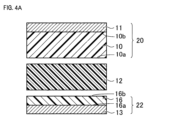
- FIG. 4A is a diagram illustrating a method for manufacturing a circuit board according to the third embodiment.
- FIG. 4B is a diagram illustrating a method for manufacturing a circuit board according to the third embodiment.
- FIG. 4A is a diagram illustrating a method for manufacturing a circuit board according to the third embodiment.
- FIG. 4B is a diagram illustrating a method for manufacturing a circuit board according to the third embodiment.
- FIG. 4C is a diagram illustrating a method for manufacturing a circuit board according to the third embodiment.
- FIG. 5 is a schematic cross-sectional view of a circuit board according to the fourth embodiment.
- FIG. 6 is a schematic cross-sectional view of a circuit board according to the fifth embodiment.
- FIG. 7A is a diagram illustrating a method for manufacturing a circuit board according to the fifth embodiment.
- FIG. 7B is a diagram illustrating a method for manufacturing a circuit board according to the fifth embodiment.
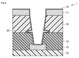
- FIG. 8 is a diagram for explaining the gouging.
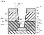
- FIG. 9 is a diagram for explaining a method for measuring the length of the hollow.
- the circuit board 1 includes an adhesive layer 12 (corresponding to a bonding sheet) mainly composed of polypropylene.
- the inner wall surfaces of the fluororesin layer 10 and the adhesive layer 12 are plated to form a via hole.
- the portion of the gouging 25 is difficult to plate.
- a portion of the via hole is insufficiently plated, which tends to reduce the reliability of the circuit board.
- the present disclosure aims to provide a circuit board in which a fluororesin layer and an adherend layer are bonded by pressing at low temperature.
- the present disclosure aims to provide a circuit board in which the occurrence of gouging near the interface between the fluororesin layer and the adhesive layer is suppressed when a through hole is formed penetrating the fluororesin layer and the adhesive layer.
- the present disclosure it is possible to provide a circuit board in which a fluororesin layer and an adherend layer are bonded by pressing at a low temperature.
- the present disclosure can provide a circuit board in which, when a through hole is formed penetrating the fluororesin layer and the adhesive layer, the occurrence of gouging near the interface between the fluororesin layer and the adhesive layer is suppressed.
- the circuit board of the present disclosure is A fluororesin layer; An adherend layer; An adhesive layer that adheres the fluororesin layer and the adherend layer,
- the fluororesin layer contains polytetrafluoroethylene and a first inorganic filler, The content of the first inorganic filler in the fluororesin layer is 50% by volume or more and 66% by volume or less,
- the adhesive layer includes a resin and a second inorganic filler, The content of the fluororesin in the resin is 5% by mass or less, The content of the second inorganic filler in the adhesive layer is 29 vol% or more and 47 vol% or less,
- the circuit board has a through hole formed therethrough that penetrates the fluororesin layer and the adhesive layer.
- the present disclosure it is possible to provide a circuit board in which a fluororesin layer and an adherend layer are bonded by pressing at low temperature. Furthermore, according to the present disclosure, it is possible to provide a circuit board in which the occurrence of gouging near the interface between the fluororesin layer and the adhesive layer is suppressed even when a through hole is formed that penetrates the fluororesin layer and the adhesive layer.
- low temperature means a temperature of 180°C or lower.
- the first inorganic filler may contain silica. This can reduce the thermal expansion coefficient of the fluororesin layer.
- the thermal expansion coefficient of the fluororesin layer is the linear expansion coefficient in the thickness direction of the fluororesin layer (thermal expansion coefficient for the length along an axis perpendicular to the layer surface of the fluororesin layer).
- the second inorganic filler may contain silica. This can further suppress the occurrence of gouging.
- the second inorganic filler may contain boron nitride. This can further suppress the occurrence of gouging.
- At least one of the inner wall surface of the fluororesin layer that defines a portion of the through hole and the inner wall surface of the adhesive layer that defines a portion of the through hole may have a recess, and the length of the recess may be less than 25 ⁇ m. This improves the reliability of the circuit board.
- the ratio A/B of the elastic modulus A at 160°C to the elastic modulus B at 20°C of the adhesive layer may be 0.08 or less. This improves the adhesion between the fluororesin layer and the metal layer at low temperatures.
- the resin may contain a polyolefin or a polystyrene-based elastomer. This improves the adhesion between the fluororesin layer and the metal layer at low temperatures.
- the adherend layer may include a first metal layer and a first resin layer, and the first metal layer may be provided on a surface of the first resin layer facing the fluororesin layer.
- the adherend layer may include a first metal layer and a first resin layer, and the first resin layer may be provided on a surface of the first metal layer facing the fluororesin layer. This allows a circuit to be formed on the first metal layer.
- the fluororesin layer includes a first main surface facing the adhesive layer and a second main surface opposite to the first main surface
- the circuit board may further include a second metal layer provided on the second main surface.
- connection portion electrically connecting the first metal layer and the second metal layer is further provided,
- the connection portion may be formed in the through hole.
- the first metal layer may be formed in an area that overlaps with the through hole when viewed from a direction perpendicular to the second main surface. This allows the shape of the connection portion to be precisely defined.
- the second metal layer may be formed in an area that overlaps with the through hole when viewed from a direction perpendicular to the first main surface. This allows the shape of the connection portion to be precisely defined.
- a method for producing a circuit board according to the present disclosure is a method for producing the circuit board according to any one of (1) to (13) above, comprising the steps of:
- the method for manufacturing a circuit board includes a step of maintaining a laminate in which the fluororesin layer, the adhesive layer, and the adherend layer are laminated in this order at a temperature of 180° C. or less to soften the adhesive layer, thereby adhering the fluororesin layer and the adherend layer to each other.
- the present disclosure it is possible to provide a circuit board in which a fluororesin layer and an adherend layer are bonded by pressing at low temperatures. Furthermore, according to the present disclosure, it is possible to provide a circuit board in which the occurrence of gouging near the interface between the fluororesin layer and the adhesive layer is suppressed, even when a through hole is formed that penetrates the fluororesin layer and the adhesive layer.
- a method for manufacturing a circuit board includes: A step of preparing a fluororesin laminate including a fluororesin layer including a first main surface and a second main surface opposite to the first main surface, and a second metal layer provided on the second main surface; A step of preparing a first resin laminate including a first resin layer including a third main surface and a fourth main surface opposite to the third main surface, and a first metal layer provided on the third main surface; providing an adhesive layer; a step of laminating the fluororesin laminate, the adhesive layer, and the first resin laminate in this order such that the first main surface is in contact with the adhesive layer, and maintaining the adhesive layer at a temperature of 180° C.
- the fluororesin layer contains polytetrafluoroethylene and a first inorganic filler, The content of the first inorganic filler in the fluororesin layer is 50% by volume or more and 66% by volume or less,
- the adhesive layer includes a resin and a second inorganic filler, The content of the fluororesin in the resin is 5% by mass or less, In the method for producing a circuit board, the adhesive layer has a content of the second inorganic filler of 29 volume % or more and 47 volume % or less.
- the present disclosure it is possible to provide a circuit board in which a fluororesin layer and an adherend layer are bonded by pressing at low temperatures. Furthermore, according to the present disclosure, it is possible to provide a circuit board in which the occurrence of gouging near the interface between the fluororesin layer and the adhesive layer is suppressed, even when a through hole is formed that penetrates the fluororesin layer and the adhesive layer.
- the step of preparing the first resin laminate may further include a step of forming a first circuit in the first resin laminate by etching at least a part of the first metal layer. This allows the first circuit to be embedded in the adhesive layer.
- the step of preparing the fluororesin laminate may further include a step of forming a second circuit in the fluororesin laminate by etching at least a part of the second metal layer. In this way, the wiring density of the circuit board can be increased by forming the second circuit.
- the step of forming the first laminate may further include a step of forming a second circuit in the fluororesin laminate by etching at least a part of the second metal layer. In this way, the wiring density of the circuit board can be increased by forming the second circuit.
- the through hole may be formed by laser processing. This allows the through hole to be formed with high precision.
- At least one of the inner wall surface of the fluororesin layer and the inner wall surface of the adhesive layer has a hollow,
- the length of the recess may be less than 25 ⁇ m, which improves the reliability of the circuit board.
- the expression "from A to B" means a range from the upper limit to the lower limit (greater than or equal to A and less than or equal to B). If no unit is stated for A, and a unit is stated only for B, the units for A and B are the same.
- the compound when a compound is represented by a chemical formula and the atomic ratio is not limited, the compound includes compounds with any conventionally known atomic ratio and is not limited to compounds within the stoichiometric range.
- the lower limit and upper limit of a numerical range are each one or more numerical values
- a combination of any one numerical value stated as the lower limit and any one numerical value stated as the upper limit is deemed to be disclosed.
- a1, b1, and c1 are stated as the lower limit and a2, b2, and c2 are stated as the upper limit
- a1 to a2, a1 to b2, a1 to c2, b1 to a2, b1 to b2, b1 to c2, c1 to a2, c1 to b2, and c1 to c2 are deemed to be disclosed.
- the circuit board 1 of embodiment 1 includes a fluororesin layer 10, an adherend layer 17, and an adhesive layer 12 that adheres the fluororesin layer 10 and the adherend layer 17.
- the fluororesin layer 10 includes polytetrafluoroethylene and a first inorganic filler.
- the content of the first inorganic filler in the fluororesin layer 10 is 50% by volume or more and 66% by volume or less.
- the adhesive layer 12 includes a resin and a second inorganic filler.
- the content of the fluororesin in the resin is 5% by mass or less.
- the content of the second inorganic filler in the adhesive layer 12 is 29% by volume or more and 47% by volume or less.
- the circuit board 1 includes a through hole penetrating the fluororesin layer 10 and the adhesive layer 12.
- the circuit board 1 of embodiment 1 is a circuit board in which the fluororesin layer 10 and the adherend layer 17 are adhered by the adhesive layer 12 by pressing at low temperature.
- the circuit board 1 of embodiment 1 can have excellent reliability.
- the circuit board is not limited to a board in which a circuit is formed by processing a metal layer of a substrate.
- the circuit board of this disclosure includes a laminate formed by bonding a substrate or another circuit board to a circuit board using a bonding sheet, and a laminate provided with connection holes such as via holes.
- the circuit board 1 of the first embodiment includes a fluororesin layer 10, an adherend layer 17, and an adhesive layer 12 that adheres the fluororesin layer 10 and the adherend layer 17.
- the fluororesin layer 10 includes a first main surface 10a facing the adhesive layer 12 and a second main surface 10b opposite to the first main surface 10a.
- the adherend layer 17 includes a first resin layer 16 and a first metal layer 13 provided on a part of the surface of the first resin layer 16.
- the first resin layer 16 may be a laminate including a layer such as a metal layer, a glass cloth layer, or a nonwoven fabric layer in addition to the resin layer.
- the resin layer may include an inorganic filler. As shown in FIG. 1, the first main surface 10a may be adjacent to the adhesive layer 12.
- the first A surface 13a of the first metal layer 13 is the surface opposite to the surface of the first metal layer 13 that is in contact with the first resin layer 16.
- the first B surface 12a of the adhesive layer 12 is the surface opposite to the surface of the adhesive layer 12 that is in contact with the fluororesin layer 10.
- the first A surface 13a is in contact with the first B surface 12a.
- At least a portion of the first metal layer 13 is embedded in the adhesive layer 12.
- the third main surface 16a of the first resin layer 16 is the surface facing the first metal layer 13. The area of the third main surface 16a where the first metal layer 13 is not provided is in contact with the adhesive layer 12.
- the circuit board 1 further includes a second metal layer 11 provided on the second main surface 10b of the fluororesin layer 10.
- the second metal layer 11 is made of metal.
- the fluororesin layer 10 and the second metal layer 11 may be in contact with each other.
- the fluororesin layer 10 and the second metal layer 11 may be bonded to each other by disposing a thin adhesive film (not shown) between the fluororesin layer 10 and the second metal layer 11.
- the circuit board 1 further includes a connection portion 14.
- the connection portion 14 is made of metal and electrically connects the first metal layer 13 and the second metal layer 11.
- a through hole is formed in the circuit board 1, penetrating the fluororesin layer 10 and the adhesive layer 12. That is, the fluororesin layer 10 and the adhesive layer 12 have a through hole penetrating the fluororesin layer 10 and the adhesive layer 12.
- the connection portion 14 is formed in the through hole. More specifically, the connection portion 14 is formed on the inner wall surface of the fluororesin layer 10 that defines a part of the through hole and on the inner wall surface that defines a part of the adhesive layer 12.
- the first metal layer 13 defines the bottom surface of the through hole, and the connection portion 14 is also formed on the bottom surface.
- the second metal layer 11 When the circuit board 1 is viewed from a direction perpendicular to the second main surface 10b, the second metal layer 11 is not formed in the area that overlaps with the through hole.
- the second metal layer 11 has an opening that leads to the through hole.
- the first metal layer 13 When the circuit board 1 is viewed from a direction perpendicular to the second main surface 10b, the first metal layer 13 is formed in the area that overlaps with the through hole.
- the first metal layer 13 is the via bottom that fills the through hole.
- the cross-sectional area of the through hole increases continuously from the first metal layer 13 to the second metal layer 11.
- the cross-sectional area of the through hole is the cross-sectional area when viewed in a cross section perpendicular to the direction from the first metal layer 13 to the second metal layer 11.
- the fluororesin layer contains polytetrafluoroethylene and a first inorganic filler.
- Polytetrafluoroethylene has a small dielectric constant and a small dielectric loss tangent. Therefore, a circuit board using the fluororesin layer as an insulating layer has good high frequency characteristics.
- the volumetric content of the first inorganic filler in the fluororesin layer is 50% by volume or more and 66% by volume or less. This provides excellent dimensional stability due to the small thermal expansion coefficient of the fluororesin layer. In addition, the electrical connection reliability of the connection portion provided on the inner wall surface of the fluororesin layer is excellent.
- the lower limit of the content of the first inorganic filler in the fluororesin layer is 50% by volume, or may be 60% by volume or 63% by volume, from the viewpoint of reducing the thermal expansion coefficient.
- the thermal expansion coefficient of the fluororesin layer is small, if the content is 60% by volume or more, the thermal expansion coefficient is further reduced, and if the content is 63% by volume or more, the thermal expansion coefficient is further reduced.
- the upper limit of the content of the first inorganic filler in the fluororesin layer is 66% by volume or more, or may be 65% by volume. If the content of the first inorganic filler in the fluororesin layer is 66% by volume or less, the electrical connection stability of the connection portion is excellent, and if the content is 65% by volume or less, the electrical connection stability of the connection portion is further improved.
- the content of the first inorganic filler in the fluororesin layer may be 60% by volume or more and 66% by volume or less, or 63% by volume or more and 65% by volume or less.
- the method for measuring the volumetric content of the first inorganic filler in the fluororesin layer is as follows:
- the circuit board is cut by argon ion polishing to expose the cross section of the fluororesin layer.
- the cross section is a plane perpendicular or parallel to the lamination surface of the circuit board. If the cross section is a plane parallel to the lamination surface of the circuit board, the area of the cross section is likely to be large. If the cross section is a plane perpendicular to the lamination surface, the cross section is easily formed.
- the cross section of the fluororesin layer is observed at 10,000 times magnification using a high-resolution scanning electron microscope (SEM) (SU8020 manufactured by Hitachi High-Tech Corporation) at a low acceleration voltage to obtain an SEM image.
- SEM scanning electron microscope
- a rectangular measurement area of 8 ⁇ m x 12 ⁇ m is provided in the SEM image.
- the area-based content (area percentage) of the first inorganic filler is measured.
- the area percentage measurement is performed by extracting the first inorganic filler portion using multi-value image analysis processing software.
- the area percentage of the first inorganic filler is measured for 30 different measurement areas, and the average area percentage is calculated.
- the average area percentage of the first inorganic filler is calculated for a total of 40 measurement areas obtained by adding 10 new measurement areas whose area percentages have not yet been measured to the measurement areas whose area percentages have already been measured. If the difference between the average area percentage before the addition of the 10 measurement areas and the average area percentage of the measurement areas after the addition of the 10 measurement areas is within 1%, the average area percentage of the measurement areas after the addition is taken as the volumetric content of the first inorganic filler in the fluororesin layer. If the difference is greater than 1%, 10 measurement areas whose area percentages have not yet been measured are added, and the average area percentage of the measurement areas after the addition is calculated. This operation is repeated until the difference before and after the addition of the measurement areas is within 1%. The average area percentage when the difference before and after the addition of the measurement areas is within 1% is taken as the volumetric content of the first inorganic filler in the fluororesin layer.
- the mass-based content of the first inorganic filler in the fluororesin layer may be 50% by mass or more and 67% by mass or less. This reduces the thermal expansion coefficient of the fluororesin layer, resulting in excellent dimensional stability. In addition, the electrical connection reliability of the connection portion provided on the inner wall surface of the fluororesin layer is excellent.
- the lower limit of the content of the first inorganic filler in the fluororesin layer may be 50% by mass, 60% by mass, or 63% by mass from the viewpoint of reducing the thermal expansion coefficient.
- the thermal expansion coefficient of the fluororesin layer is reduced, if the content is 60% by mass or more, the thermal expansion coefficient is further reduced, and if the content is 63% by mass or more, the thermal expansion coefficient is further reduced.
- the upper limit of the content of the first inorganic filler in the fluororesin layer may be 67% by mass or more and 66% by mass. If the content of the first inorganic filler in the fluororesin layer is 67% by mass or less, the electrical connection stability of the connection portion is excellent, and if the content is 67% by mass or less, the electrical connection stability of the connection portion is even more excellent.
- the content of the first inorganic filler in the fluororesin layer may be 50% by mass or more and 67% by mass or less, 60% by mass or more and 66% by mass or less, or further 63% by mass or more and 65% by mass or less.
- the method for measuring the mass-based content of the first inorganic filler in the fluororesin layer is as follows. Using a thermogravimetry and differential scanning calorimeter (TG-DSC), the fluororesin layer is heated under a nitrogen atmosphere, and the temperature of the fluororesin layer is increased from 30°C to 700°C at 20°C/min. The initial weight of the fluororesin layer and the recovered weight of the recovered material after heating are measured. The ratio of the recovered weight to the initial weight is the mass-based content of the first inorganic filler in the fluororesin layer.
- TG-DSC thermogravimetry and differential scanning calorimeter
- the first inorganic filler may be a nonmetallic inorganic filler and may contain silica.
- Silica is inexpensive and easily available.
- the dielectric tangent of silica is smaller than that of many other inorganic fillers. Since the dielectric constant of silica is close to that of fluororesin, even if the first inorganic filler contains a large amount of silica, the dielectric constant of the first inorganic filler does not change significantly.
- the silica content of the first inorganic filler may be 80 mass% or more, 90 mass% or more, or 92 mass% or more from the viewpoint of reducing the decrease in the dielectric tangent of the fluororesin layer.
- the upper limit of the silica content of the first inorganic filler may be 100 mass%.
- the silica content of the first inorganic filler may be 80 mass% or more and 100 mass% or less, 90 mass% or more and 100 mass% or less, or 92 mass% or more and 100 mass% or less from the viewpoint of suppressing the decrease in the dielectric tangent of the fluororesin layer.
- the method for measuring the mass-based silica content of the first inorganic filler in the fluororesin layer is as follows. First, the weight of the recovered material obtained in the above-described method for measuring the mass-based silica content of the first inorganic filler in the fluororesin layer is measured. Using the recovered material, the silicon (Si) content of the recovered material is measured by inductively coupled plasma (ICP) analysis. Assuming that silica has a composition of SiO2 , the silica content of the recovered material is calculated from the silicon content. This content is the mass-based silica content of the first inorganic filler in the fluororesin layer.
- ICP inductively coupled plasma
- the silica in the first inorganic filler may be a natural product or a synthetic product.
- the silica in the first inorganic filler may be crystalline or amorphous.
- the silica in the first inorganic filler may be silica produced by a dry process or silica produced by a wet process. From the standpoint of availability and quality, the silica in the first inorganic filler may be synthetic silica produced by a dry process.
- the silica in the first inorganic filler may contain spherical silica. This improves processability, such as hole drilling, in the manufacturing process of the circuit board.
- the content of spherical silica in the silica may be 80% by mass or more and 100% by mass or less, 90% by mass or more and 100% by mass or less, or 95% by mass or more and 100% by mass or less.
- spherical silica refers to silica with a sphericity of 0.80 or more.
- the average particle size of the spherical silica may be 0.2 ⁇ m or more and 7.0 ⁇ m or less. This means that the fluororesin layer has a large breaking elongation, excellent mechanical strength, and excellent processability such as cutting and perforation.
- the lower limit of the average particle size of the spherical silica may be 0.2 ⁇ m, 0.5 ⁇ m, or 1.0 ⁇ m from the viewpoint of mechanical strength such as breaking elongation.
- the mechanical strength of the fluororesin layer is excellent, if it is 0.5 ⁇ m or more, the mechanical strength of the fluororesin layer is even better, and if it is 1.0 ⁇ m or more, the mechanical strength of the fluororesin layer is even better.
- the upper limit of the average particle size of the spherical silica may be 7.0 ⁇ m, 5.0 ⁇ m, or 3.0 ⁇ m from the viewpoint of processability such as cutting and perforation.
- the average particle size of the spherical silica is 7.0 ⁇ m or less, the processability of the fluororesin layer is excellent, if it is 5.0 ⁇ m or less, the processability of the fluororesin layer is even better, and if it is 3.0 ⁇ m or less, the processability of the fluororesin layer is even better.
- the average particle size of the spherical silica may be 0.2 ⁇ m or more and 7.0 ⁇ m or less, 0.5 ⁇ m or more and 5.0 ⁇ m or less, or 1.0 ⁇ m or more and 3.0 ⁇ m or less.
- the average particle size of spherical silica is the average particle size of primary particles.
- the average particle size is expressed as the mode diameter of the volumetric particle size distribution.
- the method for measuring the average particle size of spherical silica in the fluororesin layer is as follows.
- the fluororesin layer is heated under a nitrogen atmosphere using a thermogravimetric differential thermal analyzer (TG-DSC) to increase the temperature of the fluororesin layer from 30°C to 700°C at 20°C/min to obtain a recovered material.
- the recovered material contains silica.
- the recovered material is observed with a SEM. 100 silica particles are randomly selected, the particle size is measured to determine the particle size distribution, and the average particle size is calculated.
- the first inorganic filler may contain titanium oxide. Since titanium oxide has a large dielectric constant, the dielectric constant of the fluororesin layer can be adjusted by adding a small amount of titanium oxide to the first inorganic filler.
- the titanium oxide content of the first inorganic filler may be 1 mass% or more, or 2 mass% or more.
- the upper limit of the titanium oxide content of the first inorganic filler may be 20 mass% or 10 mass%.
- the titanium oxide content of the first inorganic filler may be 1 mass% or more and 20 mass% or less, or 2 mass% or more and 10 mass% or less.
- the method for measuring the mass-based titanium oxide content of the first inorganic filler in the fluororesin layer is as follows. First, the weight of the recovered material obtained in the method for measuring the mass-based content of the first inorganic filler in the fluororesin layer described above is measured. The recovered material is used to measure the titanium (Ti) content in the recovered material by ICP analysis. Assuming that the titanium oxide has a composition of TiO2 , the titanium oxide content in the recovered material is calculated from the titanium content. This content is the mass-based titanium oxide content of the first inorganic filler.
- the first inorganic filler can contain both silica and titanium oxide. This allows the temperature stability of the dielectric constant to be improved, since the dielectric constant of titanium oxide has temperature change characteristics opposite to those of the dielectric constant of silica.
- the first inorganic filler may contain nonmetallic inorganic fillers other than silica and titanium oxide (hereinafter, also referred to as "other inorganic fillers"), so long as the effect of the present disclosure is not impaired.
- other inorganic fillers include aluminum oxide, magnesium oxide, calcium oxide, talc, barium sulfate, boron nitride, zinc oxide, potassium titanate, glass, and mica.
- One type of these inorganic fillers may be used, or two or more types may be used.
- the fluororesin layer may be made of polytetrafluoroethylene, a first inorganic filler, and inevitable impurities.
- the fluororesin layer may contain a resin other than polytetrafluoroethylene (another fluororesin). That is, the fluororesin layer may be made of polytetrafluoroethylene, a first inorganic filler, another fluororesin, and inevitable impurities.
- the upper limit of the content of the other fluororesin may be 10 mass% or 5 mass%.
- the fluororesin layer may contain components other than polytetrafluoroethylene and the first inorganic filler, so long as the effects of the present disclosure are not impaired.
- the total of polytetrafluoroethylene, the first inorganic filler, other fluororesins and unavoidable impurities, and components that may be contained so long as the effects of the present disclosure are not impaired is taken as 100%, and the content of polytetrafluoroethylene, etc. is defined.
- the fluororesin layer does not have to contain glass cloth.
- a fluororesin layer that does not contain glass cloth is less likely to cause unevenness on the inner wall surface, and has excellent electrical connection reliability when a connection is formed on the inner wall surface.
- the lower limit of the average thickness of the fluororesin layer may be 20 ⁇ m, 40 ⁇ m, or 60 ⁇ m. If the average thickness is less than 20 ⁇ m, the mechanical strength may be insufficient. In addition, the effect of dimensional errors on the high-frequency characteristics of the circuit board may be large, which may make it difficult to design the circuit and manufacture the circuit components.
- the upper limit of the average thickness of the fluororesin layer may be 500 ⁇ m, 300 ⁇ m, or 150 ⁇ m. If the average thickness exceeds 500 ⁇ m, the thickness of the circuit board may be too large. In addition, if flexibility is required for the circuit board, the flexibility may be insufficient.
- the average thickness of the fluororesin layer may be 20 ⁇ m or more and 500 ⁇ m or less, 40 ⁇ m or more and 300 ⁇ m or less, or 60 ⁇ m or more and 150 ⁇ m or less.
- average thickness refers to the distance between the average line of the interface close to the front surface of the circuit board and the average line of the interface close to the back surface in a cross section cut in the thickness direction of the object.
- the “average line” is an imaginary line drawn along the interface such that the total area of the peaks (total area above the imaginary line) and the total area of the valleys (total area below the imaginary line) defined by the interface and this imaginary line are equal.
- the average thickness of each layer described below is defined in the same way.
- the upper limit of the difference between the maximum and minimum thicknesses of the fluororesin layer may be 10 ⁇ m, 5 ⁇ m, or 2 ⁇ m. If the difference is 10 ⁇ m or less, 5 ⁇ m or less, or 2 ⁇ m or less, circuit design and manufacture of circuit components become easier.
- the maximum and minimum thicknesses of the fluororesin layer are measured using an outside micrometer MDH-25MB manufactured by Mitutoyo Corporation, with the terminal surface of the measurement terminal as the "plane".
- ⁇ Adhesive Layer> In order to reduce the transmission loss of the substrate, it is conceivable to use a fluororesin for the adhesive layer, in the same way as the dielectric layer of the substrate. However, since fluororesin has a high softening temperature, a press capable of pressing at high temperatures is required. In addition, since it takes time to heat up and cool down, productivity decreases. Furthermore, when the fluororesin is cooled to room temperature and changed from the softened state to the hardened state, thermal shrinkage is large, and dimensional stability is poor. For this reason, there is a demand for an adhesive layer that is mainly made of a resin with a small dielectric tangent and can be bonded at low temperatures.
- the adhesive layer includes a resin and a second inorganic filler.
- the circuit board of the first embodiment includes a laminate in which the adhesive layer and the above-mentioned fluororesin layer are bonded together in contact with each other. Even when a through hole is formed through the fluororesin layer and the adhesive layer, the circuit board suppresses the occurrence of gouging near the interface between the fluororesin layer and the adhesive layer.
- the adhesive layer has excellent adhesive strength to both the fluororesin layer and the adherend layer. Thus, the reliability of the circuit board of the first embodiment is improved.
- the fluororesin content of the resin of the adhesive layer is 5 mass% or less.
- the resin of the adhesive layer has a reduced content of fluororesin with a high softening temperature. Thus, the adhesive layer can adhere the fluororesin layer and the adherend layer at low temperatures.
- the resin may contain a polyolefin or polystyrene-based elastomer. This has a small dielectric tangent, which reduces the transmission loss in the circuit, and a low softening temperature, which allows bonding at temperatures below 180°C.
- the polyolefin may be, for example, polyethylene or polypropylene.
- the polyolefin may be an acid-modified polyolefin. This is because acid-modified polyolefins have strong adhesive strength with the fluororesin layer and the metal layer. Acid-modified polyolefins are polyolefins that contain carboxyl groups.
- the lower limit of the polyolefin content of the resin may be 70 mass%, 80 mass%, or 90 mass%, from the viewpoint of lowering the softening temperature of the adhesive layer and obtaining good mechanical strength.
- the upper limit of the polyolefin content of the resin may be 100 mass% or 95 mass%.
- the polyolefin content of the resin may be 70 mass% or more and 100 mass% or less, 80 mass% or more and 97 mass% or less, or 90 mass% or more and 95 mass% or less.
- the lower limit of the acid-modified polyolefin content of the resin may be 70 mass%, 80 mass%, or 90 mass%, from the viewpoint of lowering the softening temperature of the adhesive layer and obtaining good mechanical strength.
- the upper limit of the acid-modified polyolefin content of the resin may be 100 mass% or 95 mass%.
- the acid-modified polyolefin content of the resin may be 70 mass% or more and 100 mass% or less, 80 mass% or more and 97 mass% or less, or 90 mass% or more and 95 mass% or less.
- polystyrene-based elastomers examples include styrene-ethylene-butylene-styrene block copolymer (SEBS), styrene-ethylene-propylene-styrene copolymer (SEPS), and styrene-ethylene-ethylene-propylene-styrene block copolymer (SEEPS).
- SEBS styrene-ethylene-butylene-styrene block copolymer
- SEPS styrene-ethylene-propylene-styrene copolymer
- SEEPS styrene-ethylene-ethylene-propylene-styrene block copolymer
- the lower limit of the polystyrene-based elastomer content of the resin may be 50 mass%, 55 mass%, or 60 mass%, from the viewpoint of lowering the softening temperature of the adhesive layer and obtaining good mechanical strength.
- the upper limit of the polystyrene-based elastomer content of the resin may be 100 mass% or 80 mass%.
- the polystyrene-based elastomer content of the resin may be 50 mass% or more and 100 mass% or less, 55 mass% or more and 90 mass% or less, or 60 mass% or more and 80 mass% or less.
- the adhesive layer may contain a resin (other resin) other than polyolefin and polystyrene-based elastomer.
- the other resin is, for example, polyphenylene ether.
- the upper limit of the content of other resins may be 30 mass%, 20 mass%, or 10 mass% if the resin is a polyolefin. In the adhesive layer, the upper limit of the content of other resins may be 50 mass%, 45 mass%, or 40 mass% if the resin is a polystyrene-based elastomer.
- the volumetric content of the second inorganic filler in the adhesive layer is 29% by volume or more and 47% by volume or less. This allows the length of the gouge to be smaller than 25 ⁇ m. Since the softening temperature of the adhesive layer is low, the large thermal expansion coefficient of the adhesive layer does not pose a problem. Therefore, the adhesive layer does not need to contain the second inorganic filler in order to reduce the thermal expansion coefficient of the adhesive layer.
- the lower limit of the content of the second inorganic filler in the adhesive layer may be 29% by volume, 33% by volume, or 38% by volume from the viewpoint of reducing the length of the gouge.
- the upper limit of the content of the second inorganic filler in the adhesive layer may be 47% by volume, 43% by volume, or 40% by volume from the viewpoint of maintaining a strong adhesive strength.
- the content of the second inorganic filler in the adhesive layer is 29% by volume or more and 47% by volume or less, 33% by volume or more and 43% by volume or less, or 38% by volume or more and 40% by volume or less.
- the method for measuring the volumetric content of the second inorganic filler in the adhesive layer is as follows.
- the circuit board is cut by argon ion polishing to expose the cross section of the adhesive layer.
- the cross section is a plane perpendicular to the laminated surface of the circuit board or a perpendicular plane. If the cross section is a plane parallel to the laminated surface of the circuit board, the area of the cross section is likely to be large. If the cross section is a plane perpendicular to the laminated surface, the cross section is easily formed.
- the cross section of the adhesive layer is observed at 10,000 times magnification using a high-resolution scanning electron microscope (SEM) (SU8020 manufactured by Hitachi High-Tech Corporation) at a low acceleration voltage to obtain an SEM image.
- SEM scanning electron microscope
- a rectangular measurement area of 5 ⁇ m x 12 ⁇ m is provided in the SEM image.
- the area-based content (area percentage) of the second inorganic filler is measured.
- the area percentage is measured by extracting the part of the second inorganic filler using multi-value image analysis processing software.
- the area percentage of the second inorganic filler is measured for 30 different measurement areas, and the average area percentage is calculated.
- the average area percentage of the second inorganic filler is calculated for a total of 40 measurement areas obtained by adding 10 new measurement areas whose area percentages have not yet been measured to the measurement areas whose area percentages have already been measured. If the difference between the average area percentages before the addition of the 10 measurement areas and the average area percentages of the measurement areas after the addition of the 10 measurement areas is within 1%, the average area percentages of the measurement areas after the addition are taken as the volumetric content of the second inorganic filler in the adhesive layer. If the difference is greater than 1%, 10 measurement areas whose area percentages have not yet been measured are added, and the average area percentages of the measurement areas after the addition are calculated. This operation is repeated until the difference before and after the addition of the measurement areas is within 1%. The average area percentages when the difference before and after the addition of the measurement areas is within 1% are taken as the volumetric content of the second inorganic filler in the adhesive layer.
- the mass-based content of the second inorganic filler in the adhesive layer may be 40% by mass or more and 70% by mass or less. This allows the length of the gouge to be smaller than 25 ⁇ m.
- the lower limit of the content of the second inorganic filler in the adhesive layer may be 40% by mass, 50% by mass, or 55% by mass.
- the upper limit of the content of the second inorganic filler in the adhesive layer may be 70% by mass, 67% by mass, or 63% by mass.
- the content of the second inorganic filler in the adhesive layer may be 40% by mass or more and 70% by mass or less, 50% by mass or more and 67% by mass or less, or 55% by mass or more and 63% by mass or less.
- the method for measuring the mass content of the second inorganic filler in the adhesive layer is as follows. Using a thermogravimetric differential scanning calorimeter (TG-DSC), the adhesive layer is heated under a nitrogen atmosphere, and the temperature of the adhesive layer is increased from 30°C to 700°C at 20°C/min. The initial weight of the adhesive layer and the recovered weight of the recovered material after heating are measured. The ratio of the recovered weight to the initial weight is the mass content of the second inorganic filler in the adhesive layer.
- TG-DSC thermogravimetric differential scanning calorimeter
- the absolute value Z of the difference between X and Y may be 0 or more and 17 or less, or may be 0 or more and 10 or less, or may be 0 or more and 7 or less. This allows the length of the gouge to be further reduced.
- the second inorganic filler may be a non-metallic inorganic filler and may contain silica.
- the specific gravity of silica is relatively small.
- the surface of silica is easy to treat, for example, with a silane coupling agent. Therefore, silica is easy to mix with the resin of the adhesive layer.
- Silica is inexpensive and easy to obtain.
- the silica content of the second inorganic filler may be 50% by mass or more and 100% by mass or less, 70% by mass or more and 100% by mass or less, or 90% by mass or more and 100% by mass or less.
- the method for measuring the mass-based silica content of the second inorganic filler in the adhesive layer is as follows. First, the recovered weight of the recovered material obtained in the method for measuring the mass-based silica content of the second inorganic filler in the adhesive layer described above is measured. Using the recovered material, the silicon (Si) content of the recovered material is measured by ICP analysis. Assuming that silica has a composition of SiO2 , the silica content of the recovered material is calculated from the silicon content. This content is the mass-based silica content of the second inorganic filler in the adhesive layer.
- the second inorganic filler may contain boron nitride. Since boron nitride has a low dielectric constant, even if the second inorganic filler contains a large amount of boron nitride, the dielectric constant of the adhesive layer does not change significantly. In addition, since boron nitride has a high thermal conductivity, the heat dissipation of the circuit board can be improved by having the second inorganic filler contain boron nitride. From the viewpoint of improving thermal conductivity, the content of boron nitride in the second inorganic filler may be 20 mass% or more, 40 mass% or more, or 60 mass% or more.
- the upper limit of the content of boron nitride in the second inorganic filler may be 100 mass%.
- the content of boron nitride in the second inorganic filler may be 20 mass% or more and 100 mass% or less, 40 mass% or more and 100 mass% or less, or 60 mass% or more and 100 mass% or less.
- the method for measuring the mass-based content of boron nitride in the second inorganic filler in the adhesive layer is as follows. First, the recovered weight of the recovered material obtained in the method for measuring the mass-based content of the second inorganic filler in the adhesive layer described above is measured. The recovered material is used to measure the boron content in the recovered material by ICP analysis. Assuming that boron nitride has a composition of BN, the boron nitride content in the recovered material is calculated from the boron content. This content is the mass-based content of boron nitride in the second inorganic filler in the adhesive layer.
- the second inorganic filler can contain both silica and boron nitride. This can suppress the occurrence of gouging and improve the heat dissipation of the circuit board. Furthermore, even if the second inorganic filler contains a large amount of silica and boron nitride, the dielectric constant of the adhesive layer does not change significantly.
- the second inorganic filler may contain nonmetallic inorganic fillers other than silica and boron nitride (hereinafter also referred to as "other inorganic fillers"), so long as the effect of the present disclosure is not impaired.
- other inorganic fillers include titanium nitride, aluminum oxide, magnesium oxide, calcium oxide, talc, barium sulfate, boron nitride, zinc oxide, potassium titanate, glass, and mica.
- One type of these other inorganic fillers may be used, or two or more types may be used.
- the adhesive layer may be composed of a resin, a second inorganic filler, and inevitable impurities.
- the adhesive layer may contain components other than the resin and the second inorganic filler, provided that the effects of the present disclosure are not impaired.
- components other than the resin and the second inorganic filler include flame retardants, flame retardant assistants, pigments, antioxidants, reflective agents, masking agents, lubricants, processing stabilizers, plasticizers, and foaming agents.
- the adhesive layer may contain one or more of these components.
- the upper limit of the content of the components in the adhesive layer may be 25% by mass, or 10% by mass.
- the ratio A/B of the adhesive layer's elastic modulus A at 160°C to its elastic modulus B at 20°C may be 0.08 or less. This allows the adhesive layer to fill between the circuits of the metal layer even when pressed at a temperature of 180°C or less. In addition, the adhesive layer and the metal layer are closely attached to each other, improving the adhesive strength between the adhesive layer and the metal layer. From the viewpoint of ensuring adhesiveness, the upper limit of the ratio A/B may be 0.08, 0.05, or 0.02. The lower limit of the ratio A/B may be 0.0001, 0.0005, or 0.001. The ratio A/B may be 0.0001 or more and 0.08 or less, 0.0005 or more and 0.05 or less, or 0.001 or more and 0.02 or less.
- the method for measuring the elastic modulus B of the adhesive layer at 20°C and the elastic modulus A at 160°C is as follows. Using a dynamic viscosity measuring (DMS) device, a vibration with a frequency of 1 Hz is applied to the bonding sheet constituting the adhesive layer while the bonding sheet is heated to increase the temperature of the bonding sheet from 15°C to 170°C at a rate of 10°C/min, and the elastic modulus at 20°C and 160°C is measured.
- DMS dynamic viscosity measuring
- the glass transition temperature of the adhesive layer may be 160°C or lower. This improves the adhesiveness when the fluororesin layer and the metal layer are pressed and bonded at a temperature of 180°C or lower.
- the upper limit of the glass transition temperature of the adhesive layer may be 160°C, 150°C, 120°C, or 100°C. If the glass transition temperature of the adhesive layer is 150°C or lower, the adhesiveness is further improved, if it is 120°C or lower, the adhesiveness is further improved, and if it is 100°C or lower, the adhesiveness is improved even more.
- the lower limit of the glass transition temperature of the adhesive layer may be 10°C. If the glass transition temperature of the adhesive layer is 10°C or higher, the heat resistance is improved.
- the glass transition temperature of the adhesive layer may be 30°C or higher and 160°C or lower, 30°C or higher and 150°C or lower, or 30°C or higher and 120°C or lower. If an adhesive layer has multiple glass transition temperatures, the glass transition temperature of the adhesive layer is determined to be the highest glass transition temperature among the glass transition temperatures attributable to resins whose volume ratio to the total volume of all resins is 10% or more.
- the method for measuring the glass transition temperature of the adhesive layer is as follows.
- a dynamic viscosity measurement (DMS) device is used to measure the glass transition temperature of the adhesive layer. While applying a vibration of 1 Hz frequency to the bonding that constitutes the adhesive layer, the bonding sheet is heated to increase the temperature of the bonding sheet from 15°C to 170°C at a rate of 10°C/min. Within this temperature range, the complex modulus of elasticity of the bonding sheet is measured, and the temperature at which tan ⁇ peaks, with the phase angle being ⁇ , is regarded as the glass transition temperature.
- DMS dynamic viscosity measurement
- the lower limit of the average thickness of the adhesive layer may be 5 ⁇ m, 20 ⁇ m, or 30 ⁇ m from the viewpoint of adhesion.
- the upper limit of the average thickness of the adhesive layer may be 100 ⁇ m, 70 ⁇ m, or 50 ⁇ m from the viewpoint of finishing the laminate thin.
- the average thickness of the adhesive layer may be 5 ⁇ m or more and 100 ⁇ m or less, 20 ⁇ m or more and 70 ⁇ m or less, or 30 ⁇ m or more and 50 ⁇ m or less.
- the average thickness of the adhesive layer may be greater than or equal to the thickness of the circuit from the viewpoint of filling between the circuits.
- the average thickness of the adhesive layer may be 10 ⁇ m or more thicker than the thickness of the circuit, or may be 20 ⁇ m or more thicker than the thickness of the circuit.
- the occurrence of gouging near the interface between the fluororesin layer 10 and the adhesive layer 12 is suppressed on the inner wall surface of the fluororesin layer and the inner wall surface of the adhesive layer. Even if gouging occurs in the fluororesin layer, the length of the gouging can be made very small.
- at least one of the inner wall surface of the fluororesin layer and the inner wall surface of the adhesive layer has a gouging. The length of the gouging may be less than 25 ⁇ m, less than 20 ⁇ m, or less than 15 ⁇ m.
- the inner wall surface of the fluororesin layer and the inner wall surface of the adhesive layer do not need to have a gouging.
- the circuit board 1 is cut along a plane including the central axis L1 of the through hole to expose a cross section of the laminate of the fluororesin layer 10 and the adhesive layer 12.
- the central axis L1 corresponds to a line connecting the center (geometric center) of the opening of the through hole in the second main surface 10b of the fluororesin layer 10 and the center (geometric center) of the opening of the through hole in the first B surface 12a of the adhesive layer 12.
- the interface between the fluororesin layer 10 and the adhesive layer 12 is defined as the interface P1.
- a straight line between the interface P1 and the fluororesin layer 10, parallel to the interface P1, and 10 ⁇ m away from the interface P1 is defined as the line P1F.
- a straight line between the interface P1 and the adhesive layer 12, parallel to the interface P1, and 10 ⁇ m away from the interface P1 is defined as the line P1B.
- a gouge in the region between the interface P1 and the line P1F, or in the region between the interface P1 and the line P1F is specified. In FIG. 9, the gouge 25 exists in the interface P1 and in the region between the interface P1 and the line P1F. When the interface has unevenness, the interface is defined by its average line.
- the "average line” refers to a virtual line drawn along the interface in the cross section, and refers to a line such that the total area of the mountains (total area above the virtual line) and the total area of the valleys (total area below the virtual line) partitioned by the interface and this virtual line are equal.
- the adherend layer 17 may include a first resin layer 16 and a first metal layer 13 provided on a part of the surface of the first resin layer 16.
- the adherend layer 17 includes a first metal layer 13 and a first resin layer 16.
- the first metal layer 13 is made of metal.
- the first metal layer 13 is provided so as to be closer to the first main surface 10a of the fluororesin layer 10 than the first resin layer 16.
- the positional relationship between the first resin layer 16 and the first metal layer 13 may be reversed.
- the first resin layer 16 may be provided so as to be closer to the first main surface 10a than the first metal layer 13.
- the first metal layer 13 forms an electrical circuit.
- the electrical circuit includes an antenna.
- the first metal layer may contain copper. Copper has low resistance and small transmission loss.
- the copper content of the first metal layer may be 90% by mass or more and 100% by mass or less, 95% by mass or more and 100% by mass or less, or 99% by mass or more and 100% by mass or less.
- the first metal layer may be a layer made of copper and unavoidable impurities.
- the first metal layer may contain a metal other than copper.
- metals other than copper include silver, nickel, cobalt, zinc, and chromium. One or more of these metals may be used.
- the average thickness of the first metal layer may be 1 ⁇ m or more, 5 ⁇ m or more, or 10 ⁇ m or more from the viewpoint of reducing electrical resistance.
- the upper limit of the average thickness of the first metal layer may be 100 ⁇ m, 70 ⁇ m, or 50 ⁇ m from the viewpoint of ease of manufacture.
- the average thickness of the first metal layer may be 1 ⁇ m or more and 100 ⁇ m or less, 5 ⁇ m or more and 70 ⁇ m or less, or 10 ⁇ m or more and 50 ⁇ m or less.
- the upper limit of the maximum height roughness Rz of the surface of the first metal layer facing the first resin layer may be 2 ⁇ m or 1 ⁇ m. If the maximum height roughness Rz is 2 ⁇ m or less, the unevenness of the area where the high frequency signal is concentrated due to the skin effect is small, so that the current tends to flow linearly. Therefore, the transmission loss can be suppressed, and the high frequency characteristics of the circuit board can be further improved.
- Maximum height roughness Rz refers to the maximum height roughness measured in accordance with JIS-B-0601 (1982). Specifically, the maximum height roughness Rz is measured using a laser microscope VK-X200 manufactured by Keyence Corporation.
- the first resin layer 16 may contain epoxy resin and glass cloth. This allows the circuit board to be manufactured at low cost.
- the dielectric tangent of the first resin layer 16 may be 0.01 or less, 0.005 or less, or 0.002 or less. This reduces the transmission loss of the first metal layer, resulting in excellent high-frequency characteristics.
- the first resin layer 16 may contain fluororesin and inorganic filler. This reduces the transmission loss of the first metal layer, resulting in excellent high-frequency characteristics.
- the second metal layer 11 forms an electrical circuit.
- the electrical circuit includes an antenna.
- the second metal layer 11 may contain copper. Copper has low resistance and small transmission loss.
- the copper content of the second metal layer 11 may be 90% by mass or more and 100% by mass or less, 95% by mass or more and 100% by mass or less, or 99% by mass or more and 100% by mass or less.
- the second metal layer may be a layer made of copper and unavoidable impurities.
- the second metal layer 11 may contain a metal other than copper.
- metals other than copper include silver, nickel, cobalt, zinc, and chromium. One of these metals may be used, or two or more of them may be used.
- the average thickness of the second metal layer 11 may be 1 ⁇ m or more, 5 ⁇ m or more, or 10 ⁇ m or more from the viewpoint of reducing electrical resistance.
- the upper limit of the average thickness of the second metal layer 11 may be 100 ⁇ m, 70 ⁇ m, or 50 ⁇ m from the viewpoint of ease of manufacture.
- the average thickness of the second metal layer 11 may be 1 ⁇ m or more and 100 ⁇ m or less, 5 ⁇ m or more and 70 ⁇ m or less, or 10 ⁇ m or more and 50 ⁇ m or less.
- connection portion 14 forms a via hole.
- the connection portion 14 is formed on the end face of the second metal layer 11 that defines a part of the through hole, the through hole vicinity region of the outer surface of the second metal layer 11, the inner wall surface of the fluororesin layer 10 and the adhesive layer 12, and the surface (first A surface 13a) of the first metal layer 13 that defines a part of the through hole and is adjacent to the adhesive layer.
- the formation location of the connection portion 14 is not limited to the form of FIG. 1.
- the connection portion 14 may be electrically connected to the first metal layer 13 and the second metal layer 11.
- the connection portion 14 may be formed in the through hole.
- connection portion 14 may be formed on the inner wall surface of the fluororesin layer 10 and the adhesive layer 12, the connection portion 14 adjacent to the fluororesin layer 10 may be in contact with at least a part of the second metal layer 11, and the connection portion 14 adjacent to the adhesive layer 12 may be in contact with at least a part of the first metal layer 13.
- connection may contain copper. This gives the connection a high electrical conductivity and reduces transmission loss.
- connection portion may contain a metal other than copper.
- metals other than copper include silver, nickel, cobalt, zinc, and chromium. One or more of these metals may be used.
- the average thickness of the connection part may be 1 ⁇ m or more, 5 ⁇ m or more, or 10 ⁇ m or more.
- the upper limit of the average thickness of the connection part may be 100 ⁇ m, 50 ⁇ m, or 30 ⁇ m.
- the average thickness of the connection part may be 1 ⁇ m or more and 100 ⁇ m or less, 5 ⁇ m or more and 50 ⁇ m or less, or 10 ⁇ m or more and 30 ⁇ m or less.
- the cross-sectional area of the through hole increases continuously from the first metal layer 13 to the second metal layer 11.
- the change in the cross-sectional area of the through hole is not limited to this.
- the cross-sectional area of the through hole may be constant or may decrease continuously from the first metal layer 13 to the second metal layer 11.
- the circuit board of the embodiment may include an adhesive film disposed between the fluororesin layer and the second metal layer.
- the adhesive film may improve the adhesion between the fluororesin layer and the second metal layer.
- the adhesive thin film may contain a fluororesin.
- the resin include perfluoroalkoxyalkane (PFA) and perfluoroethylenepropene copolymer (FEP).
- the average thickness of the thin adhesive film may be 3 ⁇ m or less, so as not to interfere with the function of the fluororesin layer.
- the method for manufacturing a circuit board according to the first embodiment includes a step of bonding the fluororesin layer and the adherend layer by maintaining a laminate in which a fluororesin layer, an adhesive layer, and an adherend layer are laminated in this order at a temperature of 180° C. or less to soften the adhesive layer. This prevents the occurrence of gouging near the interface between the fluororesin layer and the adhesive layer, even when a through hole is formed through the fluororesin layer and the adhesive layer.
- Embodiment 2 Manufacturing method of circuit board (1)
- a method for manufacturing a circuit board according to an embodiment of the present disclosure (hereinafter also referred to as “embodiment 2") will be described with reference to FIGS. 1, 2A, 2B, and 2C.
- the method for manufacturing the circuit board 1 according to the second embodiment includes the steps of: A step of preparing a fluororesin laminate 20 including a fluororesin layer 10 including a first main surface 10a and a second main surface 10b opposite to the first main surface 10a, and a second metal layer 11 provided on the second main surface 10b (hereinafter also referred to as a "first step") (see FIG.
- a step of preparing a first resin laminate 22 including a first resin layer 16 including a third main surface 16a and a fourth main surface 16b opposite to the third main surface 16a, and a first metal layer 13 provided on the third main surface 16a (hereinafter also referred to as a "second step") (see FIG. 2A);
- a step of preparing an adhesive layer 12 (hereinafter also referred to as a "third step") (see FIG.
- a step (hereinafter also referred to as a "fourth step") of laminating the fluororesin laminate 20, the adhesive layer 12, and the first resin laminate 22 in this order such that the first main surface 10a is in contact with the adhesive layer 12, and maintaining the adhesive layer 12 at a temperature of 180°C or less to soften the adhesive layer 12, thereby bonding the fluororesin laminate 20 and the first resin laminate 22 to obtain a first laminate 24 (see FIG. 2B ); a step of removing at least a part of the fluororesin layer 10 and at least a part of the adhesive layer 12 to form a through hole penetrating the fluororesin layer 10 and the adhesive layer 12 (hereinafter also referred to as a "fifth step”) (see FIG.
- connection portion 14 a connection portion 14 on an inner wall surface of the fluororesin laminate 20 that defines a part of the through hole and on an inner wall surface of the adhesive layer 12 that defines a part of the through hole to obtain a circuit board 1 (see FIG.
- the fluororesin layer 10 contains polytetrafluoroethylene and a first inorganic filler, The content of the first inorganic filler in the fluororesin layer 10 is 50% by volume or more and 66% by volume or less,
- the adhesive layer 12 includes a resin and a second inorganic filler, The fluororesin content of the resin is 5% by mass or less, In the method for producing a circuit board, the content of the second inorganic filler in the adhesive layer is 29 volume % or more and 47 volume % or less.
- the fluororesin layer 10, adhesive layer 12, first metal layer 13, second metal layer 11, first resin layer 16 and connection portion 14 can be the same as those in embodiment 1.
- steps 1, 2, 3, 4, 5 and 6 are described. The order of steps 1, 2 and 3 does not have to be in this order, and any of these steps may be performed first. Steps 1, 2 and 3 may be performed simultaneously. After steps 1, 2 and 3, steps 4, 5 and 6 are performed in this order.
- a fluororesin laminate 20 is prepared, which includes a fluororesin layer 10 including a first main surface 10a and a second main surface 10b opposite to the first main surface 10a, and a second metal layer 11 provided on the second main surface 10b.
- Examples of methods for providing the second metal layer 11 on the second main surface 10b include a method of thermocompression bonding the fluororesin layer 10 and the second metal layer 11 by high-temperature pressing, a method of bonding the fluororesin layer 10 and the second metal layer 11 by disposing a thin adhesive film between them, a method of depositing a metal constituting the second metal layer 11 on the fluororesin layer 10, and a method of plating a metal constituting the second metal layer 11 on the fluororesin layer 10.
- the first step can further include a step of forming a second circuit in the fluororesin laminate 20 by etching at least a part of the second metal layer 11.
- a method for etching at least a part of the second metal layer 11 include known etching methods such as a wet etching method in which a resist pattern is formed and then the laminate is immersed in a chemical solution containing an acid or alkali, and a dry etching method using an ion beam.
- a first resin laminate 22 is prepared, which includes a first resin layer 16 including a third main surface 16a and a fourth main surface 16b opposite the third main surface 16a, and a first metal layer 13 provided on the third main surface 16a.
- Methods for providing the first metal layer 13 on one main surface of the first resin layer 16 include, for example, a method of thermocompression bonding the first resin layer 16 and the first metal layer 13 using a high-temperature press, a method of placing a thin adhesive film between the first resin layer 16 and the first metal layer 13 and bonding them, a method of vapor-depositing the metal that constitutes the first metal layer 13 on the first resin layer 16, and a method of plating the metal that constitutes the first metal layer 13 on the first resin layer 16.
- the second step may further include a step of forming a first circuit in the first resin laminate 22 by etching at least a portion of the first metal layer 13.
- a method for etching at least a portion of the first metal layer 13 include known etching methods such as a wet etching method in which a resist pattern is formed and then the laminate is immersed in a chemical solution containing an acid or alkali, and a dry etching method using an ion beam.
- the adhesive layer 12 is prepared.
- ⁇ Fourth step> the fluororesin laminate 20, the adhesive layer 12, and the first resin laminate 22 are laminated in this order such that the first main surface 10a is in contact with the adhesive layer 12, and the adhesive layer 12 is kept at a temperature of 180° C. or less to soften the adhesive layer 12, thereby bonding the fluororesin laminate 20 and the first resin laminate 22 to obtain the first laminate 24.
- the first metal layer 13 is disposed so as to be in contact with the adhesive layer 12 during lamination.
- the temperature at which the adhesive layer is maintained may be 140°C or higher and 180°C or lower, or 160°C or higher and 180°C or lower. Heat may be applied to the adhesive layer while pressure is applied to the laminate of the fluororesin laminate 20, the adhesive layer 12, and the first resin laminate 22.
- the pressure may be 0.5 MPa or higher and 8 MPa or lower, 1 MPa or higher and 6 MPa or lower, or 3 MPa or higher and 5 MPa or lower.
- the time for which the adhesive layer is maintained at the above temperature and the above pressure is applied to the laminate may be 20 minutes or longer and 120 minutes or shorter.
- the fourth step may further include a step of forming a second circuit in the fluororesin laminate 20 by etching at least a portion of the second metal layer 11.
- a method of etching at least a portion of the second metal layer 11 include known etching methods such as a wet etching method in which a resist pattern is formed and then the laminate is immersed in a chemical solution containing an acid or alkali, and a dry etching method using an ion beam.
- the second circuit may be formed in the first step or the fourth step.
- ⁇ Fifth step> At least a portion of the fluororesin layer 10 and at least a portion of the adhesive layer 12 are removed to form through-holes passing through the fluororesin layer 10 and the adhesive layer 12 .
- a dry film is attached to the second metal layer 11, and the second metal layer 11 is etched by exposure.
- the dry film is then peeled off to form an opening in the second metal layer 11.
- a mask shielding layer
- laser processing is performed on the fluororesin layer 10 and the adhesive layer 12 through the opening.
- at least a portion of the fluororesin layer 10 and at least a portion of the adhesive layer 12 are removed, forming an opening in the second metal layer 11 and a through hole penetrating the fluororesin layer 10 and the adhesive layer 12.
- the second metal layer 11 may be a laser shielding layer.
- a CO2 laser may be used for the laser processing.
- a CO2 laser is used, it is easy to make the second metal layer 11 a laser shielding layer.
- the through hole does not penetrate the first metal layer 13 and is a blind via hole.
- the first metal layer 13 may be provided on the third main surface 16a of the first resin layer 16. In this way, the distance between the first metal layer 13 and the second metal layer 11 is small, so that wiring can be arranged at a high density. In this case, the circuit formed on the first metal layer 13 is embedded in the adhesive layer 12.
- the laser is reflected by the first metal layer 13 when a through hole is formed by laser processing. Therefore, the length of the gouge near the interface between the fluororesin layer 10 and the adhesive layer 12 is larger than that of a circuit board in which the laser is not reflected. According to the present disclosure, even in a circuit board in which the first metal layer is the via bottom of the blind via hole, the length of the gouge can be suppressed. Therefore, this disclosure is particularly effective for circuit boards in which the first metal layer is the via bottom of a blind via hole.
- a pretreatment process may be performed on the inner wall surfaces of the fluororesin layer 10 and the adhesive layer 12 to clean the inner wall surfaces.
- surface treatments include potassium permanganate treatment, alkali treatment, and plasma treatment.
- the alkaline treatment is a process in which the first laminate 24 is immersed in a strong alkaline solution such as potassium hydroxide to etch the surface layers of the inner walls of the fluororesin layer 10 and the adhesive layer 12.
- a strong alkaline solution such as potassium hydroxide
- Plasma treatment is a process in which plasma is brought into contact with the inner wall surfaces of the fluororesin layer 10 and the adhesive layer 12, thereby etching the surface of the inner wall surfaces.
- atmospheric pressure plasma treatment which is one example of plasma treatment, a plasma gas such as oxygen, nitrogen, hydrogen, argon, or ammonia is sprayed onto the inner wall surfaces.
- the entire surface of the first laminate 24 may be plasma treated by placing the first laminate 24 in a plasma gas atmosphere.
- plasma of an inert gas containing a compound having a hydrophilic group may be used.
- connection parts 14 are formed on the inner wall surfaces of the fluororesin laminate 20 and the adhesive layer 12 to obtain the circuit board 1 .
- connection portion 14 In forming the connection portion 14, first, an electroless plating layer is formed by electroless plating on the end face of the second metal layer 11 that defines part of the through hole, the area near the opening (through hole) on the outer surface of the second metal layer 11, the inner wall surface of the fluororesin layer 10, the inner wall surface of the adhesive layer 12, and the surface (first A surface 13a) of the first metal layer 13 near the adhesive layer that defines part of the through hole. Next, a plating layer is formed on the electroless plating layer by electrolytic plating. This plating layer is the connection portion 14.
- the circuit board 1 according to embodiment 3 includes a fluororesin layer 10, an adherend layer 17, and an adhesive layer 12 that adheres the fluororesin layer 10 and the adherend layer 17.
- the fluororesin layer 10 includes a first main surface 10a facing the adhesive layer 12 and a second main surface 10b opposite to the first main surface 10a.
- the adherend layer 17 includes a first resin layer 16 and a first metal layer 13 provided on at least a part of the surface of the first resin layer 16.
- the first resin layer 16 and the first metal layer 13 may be in contact with each other.
- a resin layer, a metal layer, an adhesive layer, or a laminate thereof may be disposed between the first resin layer 16 and the first metal layer 13 to bond the first resin layer 16 and the first metal layer 13.
- the circuit board 1 of the third embodiment includes a first resin layer 16 provided between the first metal layer 13 and the adhesive layer 12.
- the fourth main surface 16b of the first resin layer 16, which is far from the first metal layer 13, is in contact with the first B surface 12a of the adhesive layer 12, which is far from the fluororesin layer 10.
- the circuit board 1 further includes a second metal layer 11 provided on the second main surface 10b of the fluororesin layer 10.
- the fluororesin layer 10 and the second metal layer 11 may be in contact with each other.
- the fluororesin layer 10 and the second metal layer 11 may be bonded to each other by disposing a thin adhesive film (not shown) between the fluororesin layer 10 and the second metal layer 11.
- the circuit board 1 further includes a connection portion 14.
- the connection portion 14 is made of metal and electrically connects the first metal layer 13 and the second metal layer 11.
- the second metal layer 11, the fluororesin layer 10, the adhesive layer 12, and the first resin layer 16 include through holes penetrating them.
- the connection portion 14 is formed in the through holes. More specifically, the connection portion 14 is formed on the inner wall surface of the second metal layer 11, the inner wall surface of the fluororesin layer 10, the inner wall surface of the adhesive layer 12, and the inner wall surface of the first resin layer 16.
- the first metal layer 13 defines the bottom surface of the through hole, and the connection portion 14 is also formed on the bottom surface.
- the second metal layer 11 When the circuit board 1 is viewed from a direction perpendicular to the second main surface 10b of the fluororesin layer 10, the second metal layer 11 is not formed in the area overlapping the through hole.
- the second metal layer 11 has an opening that leads to the through hole.
- the first metal layer 13 When the circuit board 1 is viewed from a direction perpendicular to the second main surface 10b of the fluororesin layer 10, the first metal layer 13 is formed in the area overlapping the through hole.
- the first metal layer 13 is a via bottom that closes the through hole.
- the through hole that penetrates the fluororesin layer 10 and the adhesive layer 12 extends to the first resin layer 16.
- the connection portion 14 formed on the inner wall surface of the fluororesin layer 10 and the adhesive layer 12 also extends to the first resin layer 16.
- the cross-sectional area of the through hole increases continuously from the first metal layer 13 to the second metal layer 11.
- connection portion 14 can be the same as those in embodiment 1.
- circuit board 1 of embodiment 3 even if a through hole is formed through the fluororesin layer 10 and the adhesive layer 12, the occurrence of gouging of the fluororesin layer 10 near the interface between the fluororesin layer 10 and the adhesive layer 12 is suppressed. Therefore, the reliability of the circuit board 1 of embodiment 3 is improved.
- the method for manufacturing the circuit board 1 according to the third embodiment includes the steps of: A step of preparing a fluororesin laminate 20 including a fluororesin layer 10 including a first main surface 10a and a second main surface 10b opposite to the first main surface 10a, and a second metal layer 11 provided on the second main surface 10b (hereinafter also referred to as "step 1B") (see FIG. 4A); A step of preparing a first resin laminate 22 including a first resin layer 16 including a third main surface 16a and a fourth main surface 16b opposite to the third main surface 16a, and a first metal layer 13 provided on the third main surface 16a (hereinafter also referred to as "step 2B”) (see FIG.
- step 4A A step of preparing an adhesive layer 12 (hereinafter also referred to as “step 3B") (see FIG. 4A), a step of laminating the fluororesin laminate 20, the adhesive layer 12, and the first resin laminate 22 in this order such that the first main surface 10a is in contact with the adhesive layer 12, and maintaining the adhesive layer 12 at a temperature of 180° C. or less to soften the adhesive layer 12, thereby bonding the fluororesin laminate 20 and the first resin laminate 22 to obtain a first laminate 24 (hereinafter also referred to as “step 4B”) (see FIG.
- step 5B a step of removing at least a part of the fluororesin layer 10 and at least a part of the adhesive layer 12 to form a through hole penetrating the fluororesin layer 10 and the adhesive layer 12
- step 5B a step of removing at least a part of the fluororesin layer 10 and at least a part of the adhesive layer 12 to form a through hole penetrating the fluororesin layer 10 and the adhesive layer 12
- step 5C a step of forming connection portions 14 on the inner wall surfaces of the fluororesin laminate 20 and the adhesive layer 12 to obtain the circuit board 1 (see FIG.
- the fluororesin layer 10 contains polytetrafluoroethylene and a first inorganic filler, The content of the first inorganic filler in the fluororesin layer 10 is 50% by volume or more and 66% by volume or less,
- the adhesive layer 12 includes a resin and a second inorganic filler, The fluororesin content of the resin is 5% by mass or less, In the method for producing a circuit board, the content of the second inorganic filler in the adhesive layer is 29 volume % or more and 47 volume % or less.
- Steps 1B, 2B, and 3B of embodiment 3 can be the same as steps 1, 2, and 3 of embodiment 2, respectively.
- Step 4B of embodiment 3 can be the same as step 4 of embodiment 2, except that the first resin layer 16 is laminated so as to be in contact with the adhesive layer 12.
- step 5B of embodiment 3 at least a portion of the second metal layer 11, at least a portion of the fluororesin layer 10, at least a portion of the adhesive layer 12, and at least a portion of the first resin layer 16 are removed to form through holes that penetrate these layers.
- the method for forming the through hole can be the same as the method for forming the through hole in the fifth step of embodiment 2.
- the through hole does not penetrate the first metal layer 13 and is a blind via hole.
- a pretreatment process may be performed on the inner wall surfaces of the fluororesin layer 10, the adhesive layer 12, and the first resin layer.
- the pretreatment process may be the same as the pretreatment process of the second embodiment.
- connection parts 14 are formed on the end face of the second metal layer 11 that defines a portion of the through hole, the area near the opening (through hole) on the outer surface of the second metal layer 11, the inner wall surface of the fluororesin layer 10, the inner wall surface of the adhesive layer 12, the inner wall surface of the first resin layer 16, and the surface of the first metal layer 13 near the adhesive layer that defines a portion of the through hole, to obtain a circuit board 1.
- Connection parts 14 can be formed using electroless plating and electrolytic plating as in embodiment 2.
- FIG. 4 A circuit board according to an embodiment of the present disclosure (hereinafter also referred to as "embodiment 4") and a method for manufacturing the same will be described with reference to FIG. 5.
- the circuit board 1 of embodiment 4 is basically the same as the circuit board of embodiment 1.
- the circuit board of embodiment 4 differs from the circuit board of embodiment 1 in that it includes a filling portion 26 and a third metal layer 15.
- the filling portion 26 is filled in a through hole formed in the fluororesin layer 10 and the adhesive layer 12, and contacts the connection portion 14.
- the third metal layer 15 is provided on the first main surface 10a of the fluororesin layer 10 and embedded in the adhesive layer 12.
- the filling section 26 may contain resin. This can reduce stress on the connection section, such as stress caused by thermal expansion and contraction of the circuit board and external vibration, thereby improving the electrical connection reliability of the connection section.
- the filling section 26 containing resin can be easily formed, for example, by screen printing a paste-like material.
- the filled portion 26 may be formed by filling the through hole with metal using a plating process. This can reduce stress on the connection portion, such as stress caused by thermal expansion and contraction of the circuit board and external vibration, and can improve the reliability of the electrical connection at the connection portion. Filling using a plating process can be easily performed using the connection portion 14, so the filled portion 26 can be manufactured efficiently.
- the third metal layer 15 forms an electrical circuit.
- the third metal layer 15 can have the same configuration as the first metal layer 13.
- the method for manufacturing the circuit board of embodiment 4 is basically the same as the method for manufacturing the circuit board of embodiment 2. The differences from the method for manufacturing the circuit board of embodiment 2 are described below.
- a fluororesin layer 10 including a first main surface 10a and a second main surface 10b opposite the first main surface 10a, a second metal layer 11 provided on the second main surface 10b, and a third metal layer 15 provided on the first main surface 10a are prepared, and at least a portion of the second metal layer 11 and at least a portion of the third metal layer 15 are etched to form circuits on the second main surface 10b and the first main surface 10a.
- a step is performed in which the through holes in the fluororesin layer 10 and the adhesive layer 12 are filled with, for example, a resin to form a filled portion 26 that contacts the connection portion 14. This makes it possible to obtain the circuit board 1 of the fourth embodiment.
- the circuit board 1 of embodiment 5 includes a fluororesin layer 10, an adherend layer 17, and an adhesive layer 12 that adheres the fluororesin layer 10 and the adherend layer 17.
- the fluororesin layer 10 includes a first main surface 10a facing the adhesive layer 12 and a second main surface 10b opposite to the first main surface 10a.
- the adherend layer 17 is composed of a first metal layer 13 and a first resin layer 16.
- the fourth main surface 16b of the first resin layer 16 is in contact with the first B surface 12a of the adhesive layer 12, which is farther from the fluororesin layer 10.
- the circuit board 1 further includes a second metal layer 11 provided on the second main surface 10b of the fluororesin layer 10.
- the fluororesin layer 10 and the second metal layer 11 may be in contact with each other.
- the fluororesin layer 10 and the second metal layer 11 may be bonded to each other by disposing a thin adhesive film (not shown) between the fluororesin layer 10 and the second metal layer 11.
- the circuit board 1 further includes a connection portion 14.
- the connection portion 14 is made of metal and electrically connects the first metal layer 13 and the second metal layer 11.
- a through hole is formed in the circuit board 1, penetrating the first resin layer 16, the fluororesin layer 10, and the adhesive layer 12. That is, the first resin layer 16, the fluororesin layer 10, and the adhesive layer 12 have a through hole penetrating them.
- the connection portion 14 is formed in the through hole. More specifically, the connection portion 14 is formed near the through hole on the inner wall surface of the fluororesin layer 10, the inner wall surface of the adhesive layer 12, the inner wall surface of the first resin layer 16, and the end face and outer surface of the first metal layer.
- the second metal layer 11 defines the bottom surface of the through hole, and the connection portion 14 is also formed on the bottom surface.
- the first metal layer 13 When the circuit board 1 is viewed in a direction perpendicular to the first main surface 10a, the first metal layer 13 is not formed in the area that overlaps with the through hole.
- the first metal layer 13 has an opening that leads to the through hole.
- the second metal layer 11 When the circuit board 1 is viewed in a direction perpendicular to the first main surface 10a, the second metal layer 11 is formed in the area that overlaps with the through hole.
- the second metal layer 11 is the via bottom that covers the through hole.
- the cross-sectional area of the through hole decreases continuously from the first metal layer 13 to the second metal layer 11.
- the method for manufacturing the circuit board of embodiment 5 is basically the same as the method for manufacturing the circuit board of embodiment 2. The differences from the method for manufacturing the circuit board of embodiment 2 are described below.
- the first laminate 24 is obtained in the same manner as in the first to fourth steps of the second embodiment (see FIG. 7A).
- an opening is formed in the first metal layer 13 in the fifth step of the second embodiment.
- laser processing is performed on the first resin layer 16, the adhesive layer 12, and the fluororesin layer 10 through the opening.
- a through hole is formed through the opening that penetrates the first resin layer 16, the adhesive layer 12, and the fluororesin layer 10 (see FIG. 7B).
- the first resin layer 16, the fluororesin layer 10, and the adhesive layer 12 have a through hole that penetrates them.
- an electroless plating layer is formed by electroless plating on the end face of the first metal layer 13 that defines a portion of the through hole, the area near the opening (through hole) on the outer surface of the first metal layer 13, the inner wall surfaces of the fluororesin layer 10 and the adhesive layer 12, and the surface near the adhesive layer of the second metal layer 11 that defines a portion of the through hole.
- a plating layer is formed on the electroless plating layer by electrolytic plating (see FIG. 6). This plating layer is the connection portion 14.
- the layer in contact with the second metal layer 11, which is the via bottom of the blind via hole is the fluororesin layer 10, which has excellent heat resistance. Therefore, the length of the gouge is small.
- a fluororesin laminate 20 including a fluororesin layer 10 and a second metal layer 11 provided on one main surface of the fluororesin layer was prepared.
- the fluororesin laminate 20 was produced by the following procedure.
- the raw materials shown in the "fluororesin layer” column of “raw materials” in Tables 1 and 2 were mixed in the mass ratios shown in Tables 1 and 2 to obtain a mixture.
- polytetrafluoroethylene powder referred to as "PTFE” in Tables 1 and 2
- silica silica
- titanium oxide were mixed in a mass ratio of 100:190:10.
- 17 mass% naphtha was mixed with respect to the total mass of the polytetrafluoroethylene powder, silica, and titanium oxide.
- the naphtha was removed by drying in a thermostatic chamber to obtain a fluororesin sheet (corresponding to the fluororesin layer 10) with an average thickness of 130 ⁇ m.
- a perfluoroalkoxyalkane layer with an average thickness of 2 ⁇ m was formed on one side of a copper foil (corresponding to the second metal layer) with an average thickness of 18 ⁇ m.
- This copper foil and the fluororesin sheet were laminated so that the perfluoroalkoxyalkane layer and the fluororesin sheet were in contact with each other.
- the laminate was compressed at a pressure of 4 MPa and heated at 350°C for 40 minutes to obtain a fluororesin laminate 20.
- the first resin laminate 22 is composed of a first metal layer 13 and a first resin layer 16, but in this test laminate, it is composed only of the first metal layer 13.
- the first metal layer 13 is composed of copper foil with an average thickness of 18 ⁇ m.
- the adhesive layer 12 was prepared by the following procedure, except for sample 16.
- the raw materials shown in the "Adhesive Layer” column of "Raw Materials” in Tables 1 and 2 were mixed in the mass ratios shown in Tables 1 and 2 to obtain a mixture.
- sample 1 acid-modified polypropylene and epoxy resin were dissolved in a solvent in a mass ratio of 90:10. This solution was mixed with silica so that the ratio of acid-modified polypropylene to epoxy resin to silica was 90:10:100 by mass.
- the solvent was a mixed solvent of methyl ethyl ketone, toluene, ethyl acetate, and cyclohexane in an appropriate ratio that can dissolve acid-modified polypropylene and epoxy resin.
- a mixture sheet was formed by the doctor blade method, and the solvent was removed by drying to obtain a bonding sheet (corresponding to adhesive layer 12) with an average thickness of 30 ⁇ m. The thickness of the mixture sheet can be adjusted by using the doctor blade method.
- SEEPS stands for styrene-ethylene-ethylene-propylene-styrene block copolymer
- PPE stands for polyphenylene ether.
- polytetrafluoroethylene powder, perfluoroalkoxyalkane powder (referred to as "PFA” in Tables 1 and 2), and silica were mixed in a mass ratio of 90:10:80.
- PFA perfluoroalkoxyalkane powder
- silica was mixed with respect to the total mass of the polytetrafluoroethylene powder, perfluoroalkoxyalkane powder, and silica. This was molded into a sheet, and then dried in a thermostatic chamber to remove the naphtha, obtaining a bonding sheet (corresponding to adhesive layer 12) with an average thickness of 30 ⁇ m.
- the first metal layer 13, the adhesive layer 12, and the fluororesin laminate 20 were laminated in this order so that the fluororesin layer 10 and the first metal layer 13 were in contact with the adhesive layer 12.
- the laminate was held at a temperature of 170°C for 30 minutes while a pressure of 3 MPa was applied.
- the first metal layer 13 and the fluororesin laminate 20 were bonded due to softening of the adhesive layer 12, and a test laminate could be obtained. If a test laminate could be obtained, the "Lamination Possible" column in Tables 1 and 2 indicates "Yes.”
- the first metal layer 13 and the fluororesin laminate 20 could not be bonded. If a test laminate could not be obtained, the "Lamination Possible” column in Tables 1 and 2 indicates "No.”
- ⁇ Measurement of thermal expansion coefficient of fluororesin layer The thermal expansion coefficient of the fluororesin layer before lamination of each sample was measured.
- the linear expansion coefficient in the thickness direction of the fluororesin layer was measured in the range of 20°C to 120°C using a thermal dilatometer (LIX-2) manufactured by Advance Riko Co., Ltd. As described above, in this disclosure, the linear expansion coefficient in the thickness direction of the fluororesin layer is the thermal expansion coefficient of the fluororesin layer.
- the results are shown in the "thermal expansion coefficient" column of "fluororesin layer" in Tables 1 and 2.
- thermal expansion coefficient In the "evaluation" column of "thermal expansion coefficient", the case where the thermal expansion coefficient is less than 40 ppm/°C is indicated as A, the case where the thermal expansion coefficient is 40 ppm/°C or more and less than 90 ppm/°C is indicated as B, and the case where the thermal expansion coefficient is 90 ppm/°C or more is indicated as C.
- the thermal expansion coefficient of the fluororesin layer is judged to be small.
- the thermal expansion coefficient of the fluororesin layer is judged to be large.
- volumetric content (volume %) and mass content (mass %) of the second inorganic filler in the adhesive layer of each sample are shown in the "Volume %" and “Mass %” columns of "Second inorganic filler content" in "Adhesive layer” in Tables 1 and 2.
- silica and boron nitride correspond to the first inorganic filler. When a sample contains both silica and boron nitride, the content is calculated based on the sum of these.
- the absolute value Z of the difference between X and Y was calculated based on the mass-based content X (mass%) of the first inorganic filler in the fluororesin layer and the mass-based content Y (mass%) of the second inorganic filler in the adhesive layer. The results are shown in the "Z" column in Tables 1 and 2.
- the peel strength was evaluated in accordance with JIS-K6854-2 (1999). Specifically, it was evaluated by a 180° peel test. A 66 ⁇ m thick polyimide tape ("P221" manufactured by Nitto Denko Corporation) was attached to the first metal layer of the test laminate of each sample. The thickness of the base material of the polyimide tape was 25 ⁇ m. The interface between the fluororesin layer and the adhesive layer was set as the peel starting point. The polyimide tape, the first metal layer, and the adhesive layer were pulled at 50 mm/min so that the peel direction was 180° to the adhesive surface, and the strength at the time of peeling was measured. The results are shown in the "Peel Strength" column in Tables 1 and 2.
- ⁇ Measurement of the length of the gouge> For each sample laminate, a through hole was formed from the second metal layer, and the length of the hollow in the fluororesin layer near the interface between the fluororesin layer and the adhesive layer was measured.
- the through hole was formed as follows.
- a dry film is attached to the second metal layer, exposed to light, and the second metal layer is etched. The dry film is then peeled off to form an opening of ⁇ 125 ⁇ m in the second metal layer.
- the opening is irradiated with a CO2 laser to form a through hole.
- the output of the CO2 laser is set to 18.5 W. This removes the fluororesin layer and the adhesive layer, exposing the first metal layer with a size of ⁇ 110 ⁇ m.
- the through hole is a blind via hole.
- the laminate was cut out so that a cross section including the central axis of the blind via hole was exposed, and the length of the gouge in the fluororesin layer near the interface between the fluororesin layer and the adhesive layer was measured on the cross section.
- the method for measuring the gouge length is described in embodiment 1.
- the results are shown in the "Gouge Length" column of Tables 1 and 2.
- A is indicated for a gouge length of less than 15 ⁇ m
- B for a gouge length of 15 ⁇ m or more and less than 25 ⁇ m
- C for a gouge length of 25 ⁇ m or more. If the evaluation is A or B, it is determined that the occurrence of gouges has been suppressed. If the evaluation is C, it is determined that the occurrence of gouges has not been suppressed.
- Samples 3 to 5, 7 to 10, 12, 14, and 15 are examples. These samples are circuit boards in which a fluororesin layer and an adherend layer are bonded by an adhesive layer by pressing at low temperature. It was confirmed that these samples suppress the occurrence of gouging near the interface between the fluororesin layer and the adhesive layer even when a through hole penetrating the fluororesin layer and the adhesive layer is formed.
- Samples 1, 2, 6, 11 and 13 are comparative examples. It was confirmed that in these samples, when a through hole penetrating the fluororesin layer and the adhesive layer was formed, the occurrence of gouging was not suppressed.
- Circuit board 10 Fluororesin layer 10a First main surface 10b Second main surface 11 Second metal layer 12 Adhesive layer 12a First B surface 13 First metal layer 13a First A surface 14 Connection portion 15 Third metal layer 16 First resin layer 16a Third main surface 16b Fourth main surface 17 Adherend layer 20 Fluororesin laminate 22 First resin laminate 24 First laminate 25 Hole 26 Filling portion 27 Inner wall surface L1 Central axis P1 Interface
Landscapes
- Engineering & Computer Science (AREA)
- Manufacturing & Machinery (AREA)
- Microelectronics & Electronic Packaging (AREA)
- Laminated Bodies (AREA)
Priority Applications (3)
| Application Number | Priority Date | Filing Date | Title |
|---|---|---|---|
| CN202380070598.9A CN119999341A (zh) | 2022-10-07 | 2023-09-04 | 电路基板及电路基板的制造方法 |
| JP2024555671A JPWO2024075456A1 (https=) | 2022-10-07 | 2023-09-04 | |
| DE112023004212.8T DE112023004212T5 (de) | 2022-10-07 | 2023-09-04 | Leiterplatte und Verfahren zum Herstellen einer Leiterplatte |
Applications Claiming Priority (2)
| Application Number | Priority Date | Filing Date | Title |
|---|---|---|---|
| JP2022-162209 | 2022-10-07 | ||
| JP2022162209 | 2022-10-07 |
Publications (1)
| Publication Number | Publication Date |
|---|---|
| WO2024075456A1 true WO2024075456A1 (ja) | 2024-04-11 |
Family
ID=90607792
Family Applications (1)
| Application Number | Title | Priority Date | Filing Date |
|---|---|---|---|
| PCT/JP2023/032203 Ceased WO2024075456A1 (ja) | 2022-10-07 | 2023-09-04 | 回路基板および回路基板の製造方法 |
Country Status (4)
| Country | Link |
|---|---|
| JP (1) | JPWO2024075456A1 (https=) |
| CN (1) | CN119999341A (https=) |
| DE (1) | DE112023004212T5 (https=) |
| WO (1) | WO2024075456A1 (https=) |
Citations (7)
| Publication number | Priority date | Publication date | Assignee | Title |
|---|---|---|---|---|
| JPH0592530A (ja) * | 1991-10-03 | 1993-04-16 | Daikin Ind Ltd | フツ素樹脂積層体およびその製造法 |
| JPH05301974A (ja) * | 1991-05-24 | 1993-11-16 | Rogers Corp | 粒状充填剤入り複合フィルム及びその製造法 |
| JP2002001886A (ja) * | 2000-06-09 | 2002-01-08 | Three M Innovative Properties Co | 被接着可能フッ素系材料シート、接着性フッ素系材料シート、フッ素系材料シートの接着方法および接着構造 |
| JP4938199B2 (ja) * | 2000-06-14 | 2012-05-23 | 出光興産株式会社 | ポリオレフィン系ホットメルト接着剤用樹脂 |
| WO2021235276A1 (ja) * | 2020-05-18 | 2021-11-25 | 住友電気工業株式会社 | 誘電体シートの製造方法、高周波プリント配線板用基板の製造方法、誘電体シート、及び高周波プリント配線板用基板 |
| JP2022063597A (ja) * | 2020-10-12 | 2022-04-22 | 日本メクトロン株式会社 | スルーホール形成方法およびフレキシブルプリント配線板用基板 |
| JP2022094922A (ja) * | 2020-12-15 | 2022-06-27 | 東洋インキScホールディングス株式会社 | 熱硬化性樹脂組成物、およびその利用 |
-
2023
- 2023-09-04 CN CN202380070598.9A patent/CN119999341A/zh active Pending
- 2023-09-04 DE DE112023004212.8T patent/DE112023004212T5/de active Pending
- 2023-09-04 WO PCT/JP2023/032203 patent/WO2024075456A1/ja not_active Ceased
- 2023-09-04 JP JP2024555671A patent/JPWO2024075456A1/ja active Pending
Patent Citations (7)
| Publication number | Priority date | Publication date | Assignee | Title |
|---|---|---|---|---|
| JPH05301974A (ja) * | 1991-05-24 | 1993-11-16 | Rogers Corp | 粒状充填剤入り複合フィルム及びその製造法 |
| JPH0592530A (ja) * | 1991-10-03 | 1993-04-16 | Daikin Ind Ltd | フツ素樹脂積層体およびその製造法 |
| JP2002001886A (ja) * | 2000-06-09 | 2002-01-08 | Three M Innovative Properties Co | 被接着可能フッ素系材料シート、接着性フッ素系材料シート、フッ素系材料シートの接着方法および接着構造 |
| JP4938199B2 (ja) * | 2000-06-14 | 2012-05-23 | 出光興産株式会社 | ポリオレフィン系ホットメルト接着剤用樹脂 |
| WO2021235276A1 (ja) * | 2020-05-18 | 2021-11-25 | 住友電気工業株式会社 | 誘電体シートの製造方法、高周波プリント配線板用基板の製造方法、誘電体シート、及び高周波プリント配線板用基板 |
| JP2022063597A (ja) * | 2020-10-12 | 2022-04-22 | 日本メクトロン株式会社 | スルーホール形成方法およびフレキシブルプリント配線板用基板 |
| JP2022094922A (ja) * | 2020-12-15 | 2022-06-27 | 東洋インキScホールディングス株式会社 | 熱硬化性樹脂組成物、およびその利用 |
Also Published As
| Publication number | Publication date |
|---|---|
| DE112023004212T5 (de) | 2025-08-07 |
| JPWO2024075456A1 (https=) | 2024-04-11 |
| CN119999341A (zh) | 2025-05-13 |
Similar Documents
| Publication | Publication Date | Title |
|---|---|---|
| US7334324B2 (en) | Method of manufacturing multilayer wiring board | |
| JP4576794B2 (ja) | 絶縁樹脂組成物及びその使用 | |
| CN102260378B (zh) | 复合材料、用其制作的高频电路基板及其制作方法 | |
| CN113227245B (zh) | 树脂组合物、利用其的金属层叠体和印刷电路基板及上述金属层叠体的制造方法 | |
| WO1999037704A1 (en) | Heat-resistant insulating film, raw substrate for printed wiring board using the same and method for producing the substrate | |
| TW480681B (en) | Multilayer printed wiring board and electronic equipment | |
| CN102548200A (zh) | 电路基板及其制作方法 | |
| KR101994716B1 (ko) | 금속-수지 접합 구조물 및 그 제조 방법, 그리고 상기 금속-수지 접합 구조물을 갖는 회로 기판 및 동박 적층판 | |
| CN114603945A (zh) | 金属箔、覆铜层叠板、线路板、半导体、负极材料和电池 | |
| KR101109323B1 (ko) | 인쇄회로기판의 제조방법 | |
| CN118075986A (zh) | 金属箔、线路板、覆铜层叠板、电池的负极材料和电池 | |
| JP2004221449A (ja) | 多層配線基板およびその製造方法 | |
| JP2004140268A (ja) | 高周波用多層プリント配線板の製造方法 | |
| WO2024075456A1 (ja) | 回路基板および回路基板の製造方法 | |
| US20260129754A1 (en) | Circuit board and method of manufacturing circuit board | |
| JP2001068856A (ja) | 絶縁樹脂シート及びその製造方法 | |
| JP2004111945A (ja) | 配線基板及びその製造方法 | |
| CN111757607B (zh) | 表面处理铜箔、覆铜层叠板及印制布线板 | |
| WO2022137550A1 (ja) | 積層板及び配線基板の製造方法 | |
| TW202042600A (zh) | 表面處理銅箔、覆銅積層板及印刷線路板 | |
| TWI833341B (zh) | 電路板及其製備方法 | |
| JP2008034724A (ja) | 低誘電配線板の製造方法 | |
| KR100619325B1 (ko) | 금속장적층판의 제조장치 및 제조방법 | |
| JP2004087991A (ja) | 多層配線基板の製造方法 | |
| JP2008270384A (ja) | プリント配線板及びその製造方法 |
Legal Events
| Date | Code | Title | Description |
|---|---|---|---|
| 121 | Ep: the epo has been informed by wipo that ep was designated in this application |
Ref document number: 23874585 Country of ref document: EP Kind code of ref document: A1 |
|
| WWE | Wipo information: entry into national phase |
Ref document number: 2024555671 Country of ref document: JP |
|
| WWE | Wipo information: entry into national phase |
Ref document number: 202380070598.9 Country of ref document: CN |
|
| WWE | Wipo information: entry into national phase |
Ref document number: 112023004212 Country of ref document: DE |
|
| WWP | Wipo information: published in national office |
Ref document number: 202380070598.9 Country of ref document: CN |
|
| WWP | Wipo information: published in national office |
Ref document number: 112023004212 Country of ref document: DE |
|
| 122 | Ep: pct application non-entry in european phase |
Ref document number: 23874585 Country of ref document: EP Kind code of ref document: A1 |