WO2024070744A1 - 硫化カルボニルの製造方法 - Google Patents
硫化カルボニルの製造方法 Download PDFInfo
- Publication number
- WO2024070744A1 WO2024070744A1 PCT/JP2023/033606 JP2023033606W WO2024070744A1 WO 2024070744 A1 WO2024070744 A1 WO 2024070744A1 JP 2023033606 W JP2023033606 W JP 2023033606W WO 2024070744 A1 WO2024070744 A1 WO 2024070744A1
- Authority
- WO
- WIPO (PCT)
- Prior art keywords
- gas
- plasma
- carbonyl sulfide
- raw material
- starting material
- Prior art date
- Legal status (The legal status is an assumption and is not a legal conclusion. Google has not performed a legal analysis and makes no representation as to the accuracy of the status listed.)
- Ceased
Links
Images
Classifications
-
- C—CHEMISTRY; METALLURGY
- C01—INORGANIC CHEMISTRY
- C01B—NON-METALLIC ELEMENTS; COMPOUNDS THEREOF; METALLOIDS OR COMPOUNDS THEREOF NOT COVERED BY SUBCLASS C01C
- C01B32/00—Carbon; Compounds thereof
- C01B32/70—Compounds containing carbon and sulfur, e.g. thiophosgene
- C01B32/77—Carbon oxysulfide
Definitions
- the present invention relates to a method for producing carbonyl sulfide.
- Carbonyl sulfide is known as a useful gas for etching carbon hard masks and other materials in the semiconductor manufacturing process.
- Patent Documents 1 and 2 Known methods for producing carbonyl sulfide in the gas phase include reacting carbon dioxide with carbon disulfide in the presence of a catalyst (Patent Documents 1 and 2) and reacting sulfur with carbon monoxide in the presence of a catalyst (Patent Document 3).
- Patent Document 4 a method that does not use a catalyst has also been proposed for producing carbonyl sulfide (Patent Document 4), which involves discharging a raw material gas containing starting materials consisting of CS2 and at least one selected from the group consisting of CO2 , CO, O2 and O3 while it is continuously flowing, and then continuously releasing the gas outside the discharge region.
- Patent Documents 1 to 3 all use catalysts, and as the activity of the catalyst decreases, the yield decreases, making continuous production difficult.
- the manufacturing method of Patent Document 4 does not use a catalyst, so this problem does not occur, but it is desirable to achieve a higher level of carbonyl sulfide yield.
- the present invention aims to provide a method for producing carbonyl sulfide in a high yield using a gas-phase flow method without using a catalyst.
- thermal plasma is plasma generated under a pressure of 0.03 MPa or more (e.g., atmospheric pressure), in which electrons, gas molecules, and radicals are all at high temperatures, and is distinguished from vacuum plasma, which is generated under a pressure of 0.0001 MPa or less, in which only the electrons are at high temperatures.
- the present invention aims to advantageously solve the above problems, and relates to a method for producing carbonyl sulfide, which includes a step of exciting a raw material gas containing a starting material containing carbon atoms, sulfur atoms, and oxygen atoms with thermal plasma, and a step of cooling the plasma-excited raw material gas.
- the raw material gas is excited by thermal plasma, converting the starting material containing carbon atoms, sulfur atoms, and oxygen atoms in the raw material gas into active species that can be precursors of COS, and then cooling the gas causes the active species to recombine and produce carbonyl sulfide.
- COS carbonyl sulfide
- slm Standard Liter per Minute
- the measurement conditions are a temperature of 0°C and a pressure of 1 atm (1013 hPa).
- the starting material may consist of CS2 and at least one selected from the group consisting of CO2 , CO, O2 and O3 . These combinations are advantageous in that they can suitably generate CS active species, CO active species and active species consisting of simple oxygen, which can be precursors of COS.
- carbonyl sulfide can be produced in a high yield using a gas-phase flow method without using a catalyst.
- 1 is an example of an apparatus for generating thermal plasma that can be used in the method for producing carbonyl sulfide of the present invention.
- the starting material contains carbon, sulfur and oxygen atoms.
- the starting material can be composed of these three elements (carbon, sulfur and oxygen).
- the starting material can be either an element or a compound, and usually consists of two or more kinds. It is not intended that the starting material contain only carbonyl sulfide.
- the starting material is preferably a combination of CS2 and at least one selected from the group consisting of CO2 , CO, O2 , and O3 .
- CS active species CO active species, active species consisting of simple oxygen, active species consisting of simple sulfur, etc.
- the combination of CS2 and CO2 is more preferable in terms of efficiently obtaining COS.
- the ratio of the volume of CS2 to the total volume of at least one selected from the group consisting of CO2 , CO, O2 , and O3 is preferably 0.05 or more. From the viewpoint of the selectivity of COS, it is more preferably 0.10 or more. Moreover, the volume ratio can be, for example, 2.00 or less, and from the viewpoint of obtaining good selectivity while maintaining the raw material conversion rate, it is preferably 0.70 or less.
- the raw material gas may contain an inert gas.
- the inert gas include N2 , He, Ne, Ar, Xe, and Kr, and N2 , Ar, and He are preferred, and N2 and Ar are more preferred.
- the inert gas may be used alone or in combination of two or more kinds.
- the content of the inert gas in the raw material gas can be 60% by volume or less, and preferably 30% by volume or less.
- the content of the inert gas may be 0% by volume.
- the raw material gas may contain impurities that are inevitably mixed in from the surrounding environment, in addition to the starting materials and any inert gas. Impurities include moisture.
- the raw material gas may consist of the starting materials and the inevitable impurities.
- the volume ratio of CS2 in the raw material gas is preferably 2 volume % or more. Also, the volume ratio is preferably 70 volume % or less. If it is within this range, COS can be obtained sufficiently.
- the raw material gas may contain the starting material and any inert gas when energy is applied to excite the plasma.
- the starting material and any inert gas may be supplied separately as gases to a plasma device (hereinafter simply referred to as a "plasma device") that generates thermal plasma to be used as the raw material gas, or all of them may be supplied as a premixed gas to be used as the raw material gas, or a portion of them may be supplied as a premixed gas separately from the remaining gas to be used as the raw material gas.
- a plasma device hereinafter simply referred to as a "plasma device”
- the flow rate of the raw material gas when it is supplied to the device for generating thermal plasma is preferably 15 slm or more, more preferably 20 slm or more, from the viewpoint of stabilizing the plasma.
- the upper limit of the flow rate is not particularly limited, and can be set according to the device to be used.
- the flow rate can be 5000 slm or less, but is not limited thereto.
- the flow rate of CS2 can be, for example, 0.3 slm or more and 200 slm or less, but is not limited thereto.
- the flow rates of starting materials other than CS2 and optional inert gases can be adjusted according to the flow rate of CS2 .
- the flow rate is the total amount of starting materials and optional inert gases supplied to the plasma device.
- a liquid that is either a gas under standard conditions or has a sufficiently high vapor pressure that it can be easily vaporized by heating, etc.
- Such starting materials can be supplied to the plasma device as a gas without providing a separate vaporization chamber, etc., but it is preferable to vaporize a liquid in a separately provided vaporization chamber before supplying it to the plasma device.
- Supply can be continuous.
- the supply flow rate can be controlled using a mass flow controller, etc.
- the starting material When the starting material is a liquid or solid with a low vapor pressure under standard conditions, the starting material can be vaporized in a separately provided vaporization chamber and then supplied to the plasma device.
- CS2 roofing point 46°C
- the starting material When the starting material is a solid, it can be heated to a liquid state and then introduced into the vaporization chamber, or it can be directly sublimated in the vaporization chamber.
- the starting material can be vaporized by introducing it in a liquid state into a vaporization chamber that is maintained at a temperature and pressure at which the starting material is sufficiently vaporized.
- the temperature and pressure of the vaporization chamber are preferably maintained at a temperature and pressure at which the starting material can be vaporized instantaneously.
- the starting material can be continuously introduced into the vaporization chamber as a liquid, instantly vaporized in the vaporization chamber, and continuously supplied to the plasma device as a gas. If the starting material is in a solid state, it can be heated to a liquid state and then introduced into the vaporization chamber, or it can be directly sublimated in the vaporization chamber and continuously supplied to the plasma device as a gas.
- the supply flow rate can be controlled by controlling the gas vaporized in the vaporization chamber with a mass flow controller or the like, or by controlling the starting material in liquid form when it is continuously introduced into the vaporization chamber with a liquid mass flow controller or the like.
- the vaporized starting material may be diluted with an inert gas or the like when it is introduced into the plasma device.
- the vaporization chamber may be filled with a filler to adjust the flow rate.
- the filler include Helipak, glass beads, and SUS mesh.
- CS2 when used as the starting material, it is advantageous to increase the supply amount by heating in a vaporization chamber filled with the filler.
- the manufacturing method of the present invention utilizes a reaction field created by thermal plasma.
- a plasma device that generates thermal plasma is used to generate active species that can be precursors of COS from a raw material gas in the thermal plasma region.
- Thermal plasma can be formed using electrical methods, such as arc discharge, high-frequency discharge, pulse discharge, and multi-phase AC discharge.
- the arc discharge may be a DC arc or an AC arc.
- a multi-phase AC arc is preferred because it can be used to treat a large flow rate.
- an inductively coupled high-frequency discharge plasma is advantageous in terms of efficient treatment.
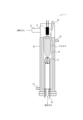
- [Plasma device] 1 shows an example of an apparatus for generating thermal plasma that can be used in the manufacturing method of the present invention. This plasma apparatus utilizes arc discharge.
- the plasma device 1 has a combustion tube 10 inside a cooling jacket 30, and the cooling jacket 30 is designed so that cooling water flows through it.
- the combustion tube 10 is preferably made of ceramic from the viewpoint of heat resistance.
- a cathode 11 is installed above the combustion tube 10, and an anode 12 is installed inside the combustion tube 10.
- An ignition wire 34 is placed on the cathode side.
- a voltage is applied between the cathode 11 and anode 12 to cause a discharge.
- the discharge conditions are not particularly limited, but can be, for example, a voltage of 300 to 600 V and a current of 1 to 20 A.
- the size of the combustion tube 10 and the distance between the electrodes can be set appropriately.
- the plasma generated by the discharge is downstream of the anode 12 side.
- a gas supply pipe 21 is connected to the plasma device 1 on the cathode 11 side.
- Raw material gas is supplied from this gas supply pipe 21, and a plasma state is created within the device, generating active species that can serve as precursors of COS.
- the installation position of the gas supply pipe 21 is not limited to the position shown in FIG. 1.
- a pipe may be inserted from the gas recovery port 22, and the raw material gas may be supplied from the pipe.
- the bottom of the plasma device 1 is provided with a gas recovery port 22.
- the raw material gas excited within the plasma device 1 is recovered from the gas recovery port 22 to the outside of the plasma device 1.
- the activated species generated by cooling during this process combine to produce carbonyl sulfide. Recovery can be performed by connecting a vacuum pump, for example, to the gas recovery port 23.
- Cooling can be performed by continuously releasing the plasma-excited source gas from the plasma device.
- the continuous release can be performed at a space velocity that corresponds to the continuous flow of the source gas.
- the plasma-excited raw gas After the plasma-excited raw gas is discharged from the plasma device, it may be further introduced into a heat exchanger for cooling.
- the type of heat exchanger is not particularly limited, and examples include air-cooling and water-cooling. Since the product after cooling may contain substances other than carbonyl sulfide, carbonyl sulfide may be separated and purified by an optional separation and purification process. Separation and purification methods include distillation, absorption by a solution, membrane separation, etc.
- Example 1 A long DC arc plasma device (volume: 6.5 L, electrode distance: 300 mm) made of Hastelloy was used as the plasma device 1.
- a cylindrical mullite ceramic tube (inner diameter 42 mm, length 600 mm) was installed inside the plasma device 1 as the combustion tube 10.
- CO2 which is the parent gas of the plasma, was introduced at 20 slm from a gas supply pipe 21 attached to the ceramic tube, and the plasma was ignited at a current value of 10 A.
- CO2 was introduced into the plasma device 1 at 20 slm from the gas supply pipe 21 and CS2 vaporized through a vaporizer heated to 75°C was introduced into the plasma device 1 at 2 slm from the gas supply pipe 21.
- the gas in the plasma device was discharged from the system through the gas recovery port 22, and the recovered gas discharged from the system was collected in an aluminum bag and detoxified with an aqueous KOH solution.
- the gas was discharged out of the system at a space velocity equivalent to the space velocity of the raw material gas introduction.
- GC-MS gas chromatography-mass spectrometry
- Example 2 (Examples 2 and 3) The procedure was the same as in Example 1, except that the flow rate of CS2 was changed to the amount shown in Table 1. The results are shown in Table 1.
- Example 4 The procedure was the same as in Example 2, except that N2 , which serves as a plasma parent gas, was further introduced through the gas supply pipe 21 at a flow rate shown in Table 1. The results are shown in Table 1.
- Table 1 shows that in the examples, carbonyl sulfide can be produced in good yield without using a catalyst.
- carbonyl sulfide can be produced in a high yield using a gas-phase flow method without using a catalyst.
Landscapes
- Chemical & Material Sciences (AREA)
- Organic Chemistry (AREA)
- Inorganic Chemistry (AREA)
- Organic Low-Molecular-Weight Compounds And Preparation Thereof (AREA)
- Carbon And Carbon Compounds (AREA)
Abstract
硫化カルボニルを、気相流通方式で、触媒を使用せずに収率よく製造可能な製造方法を提供する。炭素原子、硫黄原子及び酸素原子を含有する出発物質を含む原料ガスを、熱プラズマにて励起させる工程と、プラズマ励起させた原料ガスを冷却する工程とを含む、硫化カルボニルの製造方法である。
Description
本発明は、硫化カルボニルの製造方法に関するものである。
硫化カルボニル(COS)は、半導体製造工程におけるカーボンハードマスク等のエッチングに有用なガスとして知られている。
そして、気相で硫化カルボニルを製造する方法としては、炭酸ガスと二硫化炭素を触媒の存在下で反応させる方法(特許文献1及び2)、硫黄と一酸化炭素を触媒の存在下で反応させる方法(特許文献3)が知られている。
上記の製造方法は、いずれも触媒を使用するものであるが、触媒を使用しない方法として、CS2と、CO2、CO、O2及びO3からなる群より選ばれる少なくとも1種とからなる出発物質を含む原料ガスを連続的に流通させた状態で放電させ、次いで放電領域外に連続的に放出することを含む、硫化カルボニルの製造方法(特許文献4)も提案されている。
特許文献1~3の製造方法は、いずれも触媒を使用するものであり、触媒の活性低下に伴い収率が低下するなど、連続的な製造が困難であった。特許文献4の製造方法は、触媒を使用しないため、この問題は発生しないが、硫化カルボニルの収率については一層高いレベルの実現が望まれている。
そこで、本発明は、硫化カルボニルを、気相流通方式で、触媒を使用せずに、収率よく製造可能な製造方法を提供することを目的とする。
本発明者は、上記目的を達成するために鋭意検討を行い、所定の原料ガスを熱プラズマにて励起させ、次いで冷却することが、硫化カルボニルを収率よく得る上で有効であることを見出し、本発明を完成させた。
ここで、熱プラズマは、0.03MPa以上の圧力下(例えば、大気圧下)で発生するプラズマであり、電子・ガス分子・ラジカルが共に高温であり、0.0001MPa以下の圧力下で発生し、電子のみ高温にある真空プラズマとは区別される。
ここで、熱プラズマは、0.03MPa以上の圧力下(例えば、大気圧下)で発生するプラズマであり、電子・ガス分子・ラジカルが共に高温であり、0.0001MPa以下の圧力下で発生し、電子のみ高温にある真空プラズマとは区別される。
本発明は、上記課題を有利に解決することを目的とするものであり、炭素原子、硫黄原子及び酸素原子を含有する出発物質を含む原料ガスを、熱プラズマにて励起させる工程と、プラズマ励起させた原料ガスを冷却する工程とを含む、硫化カルボニルの製造方法に関する。
本発明の硫化カルボニルの製造方法では、原料ガスを熱プラズマにて励起させることで、原料ガスに炭素原子、硫黄原子及び酸素原子を含有する出発物質をCOSの前駆体となり得る活性種に変換し、次いで冷却することにより、上記活性種が再結合し、硫化カルボニルが生成する。このように、本発明によれば、気相流通方式で、触媒を使用せずに、硫化カルボニル(COS)を収率よく製造することができる。
本発明においては、原料ガスを、熱プラズマを形成する装置に、15slm以上の流量で連続的に供給し、前記装置内で励起させることが、原料転化率を向上させ、収率よく硫化カルボニルを得ることができる点から有利である。ここで、slm(Standard litter per minutes)は、体積流量単位であり、測定条件は温度が0℃、圧力が1atm(1013hPa)である。
出発物質は、CS2と、CO2、CO、O2及びO3からなる群より選ばれる少なくとも1種とからなることができる。これらの組み合わせは、COSの前駆体となり得るCS活性種、CO活性種、酸素単体からなる活性種を好適に生成することができる点から有利である。
本発明によれば、硫化カルボニルを、気相流通方式で、触媒を使用せずに収率よく製造することができる。
以下に、本発明の実施形態について詳しく説明する。
[原料ガス]
出発物質は炭素原子、硫黄原子及び酸素原子を含有する。出発物質は、これら3種類の元素(炭素、硫黄及び酸素)で構成されていることができる。出発物質は、単体又は化合物のいずれかであることができ、通常、2種以上からなる。出発物質が硫化カルボニルのみを含有することはないものとする。
出発物質は炭素原子、硫黄原子及び酸素原子を含有する。出発物質は、これら3種類の元素(炭素、硫黄及び酸素)で構成されていることができる。出発物質は、単体又は化合物のいずれかであることができ、通常、2種以上からなる。出発物質が硫化カルボニルのみを含有することはないものとする。
出発物質は、CS2と、CO2、CO、O2及びO3からなる群より選ばれる少なくとも1種との組み合わせが好ましい。これらの組み合わせで構成される出発物質を用いることにより、COSの前駆体となり得るCS活性種、CO活性種、酸素単体からなる活性種、硫黄単体からなる活性種等を好適に生成することができる。効率的にCOSが得られる点から、CS2とCO2との組み合わせがより好ましい。
硫化カルボニルの選択率の点から、CO2、CO、O2及びO3からなる群より選ばれる少なくとも1種の体積の合計に対する、CS2の体積の比(CS2の体積/(CO2、CO、O2及びO3からなる群より選ばれる少なくとも1種の体積の合計)は0.05以上が好ましい。COSの選択率の点からは、0.10以上がより好ましい。また、体積の比は、例えば、2.00以下とすることができ、原料転化率を維持しつつ、良好な選択率を得る点から、0.70以下が好ましい。
原料ガスは、不活性ガスを含んでいてもよい。不活性ガスとしては、N2、He、Ne、Ar、Xe、Kr等が挙げられ、N2、Ar、Heが好ましく、N2、Arがより好ましい。不活性ガスを使用する場合、不活性ガスは、1種のみでも、2種以上を併用してもよい。
不活性ガスを使用する場合、原料ガス中の不活性ガスの含有割合は、60体積%以下であることができ、30体積%以下が好ましい。不活性ガスの含有割合は0体積%であってもよい。
原料ガスは、出発物質及び任意の不活性ガス以外に、周囲環境から不可避的に混入する不純物を含み得る。不純物としては、水分が挙げられる。原料ガスは、出発物質及び不可避的不純物からなるものであることができる。
原料ガスに占めるCS2の体積の割合は、2体積%以上が好ましい。また、体積の割合は70体積%以下が好ましい。この範囲であれば、COSを十分に得ることができる。
原料ガスは、プラズマ励起のため、エネルギーを付与される際に、出発物質及び任意の不活性ガスを含んでいればよい。例えば、熱プラズマを生成するプラズマ装置(以下、単に「プラズマ装置」ともいう。)に、出発物質及び任意の不活性ガスを、それぞれ気体として、別々に供給して、原料ガスとしてもよく、全部を予め混合した気体として供給して、原料ガスとしてもよく、あるいは一部を予め混合した気体として、残部の気体とは別々に供給して、原料ガスとしてもよい。
原料ガスを、熱プラズマを形成する装置に供給する際の流量は、プラズマを安定化させる点から、15slm以上であることが好ましく、より好ましくは20slm以上である。また、流量の上限は特に限定されず、使用する装置に応じて設定することができる。例えば、流量は、5000slm以下とすることができるが、これに限定されない。
CS2を気化室で気化して供給する場合、CS2の流量は、例えば0.3slm以上200slm以下とすることができるが、これに限定されない。CS2以外の出発物質及び任意の不活性ガスは、CS2の流量の流量に応じて調整することができる。流量は、プラズマ装置に供給される出発物質及び任意の不活性ガスの合計量である。
CS2を気化室で気化して供給する場合、CS2の流量は、例えば0.3slm以上200slm以下とすることができるが、これに限定されない。CS2以外の出発物質及び任意の不活性ガスは、CS2の流量の流量に応じて調整することができる。流量は、プラズマ装置に供給される出発物質及び任意の不活性ガスの合計量である。
出発物質として、標準状態で気体であるか、あるいは蒸気圧が十分高く加熱等により容易に気化する液体を用いることが好ましい。このような出発物質は、別途気化室等を設けることなく、出発物質を気体として、プラズマ装置に供給することができるが、液体については別途設けた気化室で気化させた後、プラズマ装置に供給することが好ましい。供給は、連続的に行うことができる。供給流量の制御は、マスフローコントローラー等を用いて行うことができる。
出発物質が、標準状態で蒸気圧が低い液体又は固体である場合、出発物質を、別途設けた気化室で気化させた後、プラズマ装置に供給することができる。例えば、CS2(沸点46℃)は、気化室で気化させて、プラズマ装置に供給することが好ましい。固体の場合、加熱して液体とした後、気化室に導入しても、直接気化室で昇華させてもよい。
例えば、出発物質が十分気化する温度及び圧力に保持した気化室に、出発物質を液体の状態で導入することにより気化させることができる。気化室の温度及び圧力は、出発物質が、瞬時に気化可能な温度及び圧力に保持することが好ましい。このような気化室を利用することにより、出発物質を、液体として気化室に連続的に導入し、気化室で瞬時に気化させて、気体としてプラズマ装置に連続的に供給することができる。出発物質が固体の状態の場合、加熱して液体とした後、気化室に導入しても、直接気化室で昇華させて、気体としてプラズマ装置に連続的に供給してもよい。
供給流量の制御は、気化室で気化したガスを、マスフローコントローラー等で制御することにより行うか、あるいは、出発物質を、液の状態で気化室に連続的に導入する際に、液体マスフローコントローラー等で制御することにより行うことができる。気化させた出発物質をプラズマ装置に導入する際、不活性ガス等で希釈してもよい。
気化室には、流量の調整のため、充填物を充填してもよい。充填物としては、ヘリパック、ガラスビーズ、SUSメッシュ等があげられる。特に、出発物質としてCS2を使用する場合、充填物が充填された気化室で加熱して供給量を増加させることができ、有利である。
[放電]
本発明の製造方法は、熱プラズマが作り出す反応場を利用する。具体的には、熱プラズマを形成するプラズマ装置を用いて、熱プラズマの領域で、原料ガスからCOSの前駆体となり得る活性種を生成させる。
本発明の製造方法は、熱プラズマが作り出す反応場を利用する。具体的には、熱プラズマを形成するプラズマ装置を用いて、熱プラズマの領域で、原料ガスからCOSの前駆体となり得る活性種を生成させる。
熱プラズマの形成には、電気的な方法を利用することができ、アーク放電、高周波放電、パルス放電、多相交流放電等を利用することができる。アーク放電は、直流アークであっても、交流アークであってもよい。大流量で処理可能な点から、多相交流アークが好ましい。高周波放電については、誘導結合型高周波放電プラズマが、効率的な処理の点から有利である。
[プラズマ装置]
図1は、本発明の製造方法に使用可能な熱プラズマを形成する装置の一例である。このプラズマ装置はアーク放電を利用したものである。
図1は、本発明の製造方法に使用可能な熱プラズマを形成する装置の一例である。このプラズマ装置はアーク放電を利用したものである。
プラズマ装置1は、冷却ジャケット30内に燃焼管10を備えており、冷却ジャケット30は冷却水が流通する構造となっている。燃焼管10は耐熱性の点からセラミック製が好ましい。
燃焼管10の上方には陰極11が設置され、燃焼管10内に陽極12が設置されている。陰極側には着火用ワイヤー34が配置されている。陰極11と陽極12の間に電圧を印加し放電させる。放電の条件は、特に限定されないが、例えば、電圧300~600V、電流1~20Aとすることができる。燃焼管10の大きさ、電極間距離は、適宜設定することができる。放電により生成するプラズマは、陽極12側をプラズマの下流とする。
プラズマ装置1には、陰極11側でガス供給管21が接続している。このガス供給管21から原料ガスを供給し、装置内でプラズマ状態として、COSの前駆体となり得る活性種を生成することができる。ガス供給管21の設置位置は、図1の位置に限定されず、例えば、ガス回収口22から、管を挿入して、その管から原料ガスを供給してもよい。
プラズマ装置1の底部は、ガス回収口22が設けられている。プラズマ装置1内で励起した原料ガスをガス回収口22から、プラズマ装置1外に回収する。その際の冷却により生成した活性種が結合し、硫化カルボニルが生成する。回収は、ガス回収口23に、例えば真空ポンプを接続することにより行うことができる。
[目的物質]
プラズマ励起した原料ガスを冷却することにより、生成した活性種が再結合し、目的物質である硫化カルボニルが生成する。冷却は、プラズマ励起した原料ガスをプラズマ装置から連続的に放出することで行うことができる。連続的な放出は、原料ガスの連続的な流通に対応する空間速度で行うことができる。
プラズマ励起した原料ガスを冷却することにより、生成した活性種が再結合し、目的物質である硫化カルボニルが生成する。冷却は、プラズマ励起した原料ガスをプラズマ装置から連続的に放出することで行うことができる。連続的な放出は、原料ガスの連続的な流通に対応する空間速度で行うことができる。
プラズマ励起した原料ガスをプラズマ装置から出した後、さらに熱交換器に導入して冷却してもよい。熱交換器の方式は、特に限定されず、空冷、水冷式等が挙げられる。冷却後の生成物には、硫化カルボニル以外の物質が含まれ得るので、任意に実施し得る分離精製工程により、硫化カルボニルを分離精製してもよい。分離精製方法としては、蒸留、溶液等による吸収、膜分離等が挙げられる。
以下、実施例により本発明をより詳細に説明するが、本発明はこれらの実施例によって限定されるものではない。
(実施例1)
プラズマ装置1として、ハステロイ製のロングDCアークプラズマ装置(体積:6.5L,電極間距離:300mm)を用いた。プラズマ装置1の内部には、燃焼管10として円柱状のムライト製セラミック管(内径42mm、長さ600mm)が設置されている。セラミック管に付属したガス供給管21より、プラズマの母ガスとなるCO2を20slmで導入し、電流値10Aにてプラズマ点火した。
プラズマ装置1として、ハステロイ製のロングDCアークプラズマ装置(体積:6.5L,電極間距離:300mm)を用いた。プラズマ装置1の内部には、燃焼管10として円柱状のムライト製セラミック管(内径42mm、長さ600mm)が設置されている。セラミック管に付属したガス供給管21より、プラズマの母ガスとなるCO2を20slmで導入し、電流値10Aにてプラズマ点火した。
プラズマ点火後、ガス供給管21よりCO2を20slm及び75℃に加熱した気化器を通じて気化したCS2をガス供給管21より2slmでプラズマ装置1内に導入した。ガス回収口22より、プラズマ装置内のガスを系外に出し、系外に出した回収ガスをアルミニウムバッグに捕集した後、KOH水溶液で除害した。系外へのガスの流出は、原料ガスの導入の空間速度に相当する空間速度で行った。
捕集したガスは、質量分析ガスクロマトグラフィー(GC-MS)(アジレント社製Agilent7890A)により分析した。分析して得られたGC-MSの各成分の面積値から、硫化カルボニルの原料転化率及び収率を求めた。結果を表1に示す。
(実施例2、3)
CS2の流量を、表1に示す量に変更したこと以外は、実施例1と同様である。結果を表1に示す。
CS2の流量を、表1に示す量に変更したこと以外は、実施例1と同様である。結果を表1に示す。
(実施例4、5)
ガス供給管21より、さらにプラズマの母ガスとなるN2を、表1に示す流量で導入したこと変更したこと以外は、実施例2と同様である。結果を表1に示す。
ガス供給管21より、さらにプラズマの母ガスとなるN2を、表1に示す流量で導入したこと変更したこと以外は、実施例2と同様である。結果を表1に示す。

表1より、実施例では、触媒を使用せずに、硫化カルボニルを収率よく製造できることがわかる。
本発明によれば、硫化カルボニルを、気相流通方式で、触媒を使用せずに収率よく製造することができる。
1 プラズマ装置
10 燃焼管
11 陰極
12 陽極
21 ガス供給管
22 ガス回収口
30 冷却ジャケット
31 冷却水供給口
32 冷却水排出口
34 着火用ワイヤー
10 燃焼管
11 陰極
12 陽極
21 ガス供給管
22 ガス回収口
30 冷却ジャケット
31 冷却水供給口
32 冷却水排出口
34 着火用ワイヤー
Claims (3)
- 炭素原子、硫黄原子及び酸素原子を含有する出発物質を含む原料ガスを、熱プラズマにて励起させる工程と、プラズマ励起させた原料ガスを冷却する工程とを含む、硫化カルボニルの製造方法。
- 前記原料ガスを、熱プラズマを形成する装置に、15slm以上の流量で連続的に供給し、前記装置内で励起させる、請求項1記載の硫化カルボニルの製造方法。
- 前記出発物質が、CS2と、CO2、CO、O2及びO3からなる群より選ばれる少なくとも1種との組み合わせである、請求項1又は2記載の硫化カルボニルの製造方法。
Applications Claiming Priority (2)
| Application Number | Priority Date | Filing Date | Title |
|---|---|---|---|
| JP2022-155589 | 2022-09-28 | ||
| JP2022155589A JP2025163695A (ja) | 2022-09-28 | 2022-09-28 | 硫化カルボニルの製造方法 |
Publications (1)
| Publication Number | Publication Date |
|---|---|
| WO2024070744A1 true WO2024070744A1 (ja) | 2024-04-04 |
Family
ID=90477693
Family Applications (1)
| Application Number | Title | Priority Date | Filing Date |
|---|---|---|---|
| PCT/JP2023/033606 Ceased WO2024070744A1 (ja) | 2022-09-28 | 2023-09-14 | 硫化カルボニルの製造方法 |
Country Status (3)
| Country | Link |
|---|---|
| JP (1) | JP2025163695A (ja) |
| TW (1) | TW202413273A (ja) |
| WO (1) | WO2024070744A1 (ja) |
Citations (4)
| Publication number | Priority date | Publication date | Assignee | Title |
|---|---|---|---|---|
| JPS5659614A (en) * | 1979-08-22 | 1981-05-23 | Ihara Chem Ind Co Ltd | Manufacture of carbonyl sulfide |
| WO2012144441A1 (ja) * | 2011-04-18 | 2012-10-26 | 昭和電工株式会社 | 硫化カルボニルの製造方法 |
| JP2012224494A (ja) * | 2011-04-18 | 2012-11-15 | Showa Denko Kk | 硫化カルボニルの製造方法 |
| WO2020262319A1 (ja) * | 2019-06-27 | 2020-12-30 | 日本ゼオン株式会社 | 硫化カルボニルの製造方法 |
-
2022
- 2022-09-28 JP JP2022155589A patent/JP2025163695A/ja active Pending
-
2023
- 2023-09-14 WO PCT/JP2023/033606 patent/WO2024070744A1/ja not_active Ceased
- 2023-09-20 TW TW112135792A patent/TW202413273A/zh unknown
Patent Citations (4)
| Publication number | Priority date | Publication date | Assignee | Title |
|---|---|---|---|---|
| JPS5659614A (en) * | 1979-08-22 | 1981-05-23 | Ihara Chem Ind Co Ltd | Manufacture of carbonyl sulfide |
| WO2012144441A1 (ja) * | 2011-04-18 | 2012-10-26 | 昭和電工株式会社 | 硫化カルボニルの製造方法 |
| JP2012224494A (ja) * | 2011-04-18 | 2012-11-15 | Showa Denko Kk | 硫化カルボニルの製造方法 |
| WO2020262319A1 (ja) * | 2019-06-27 | 2020-12-30 | 日本ゼオン株式会社 | 硫化カルボニルの製造方法 |
Non-Patent Citations (1)
| Title |
|---|
| BEZUK STEVE J., MILLER LARRY L., PLATZNER I.: "Reactions of carbonyl sulfide in a radio-frequency plasma", THE JOURNAL OF PHYSICAL CHEMISTRY, AMERICAN CHEMICAL SOCIETY, vol. 87, no. 1, 1 January 1983 (1983-01-01), pages 131 - 136, XP055780958, ISSN: 0022-3654, DOI: 10.1021/j100224a030 * |
Also Published As
| Publication number | Publication date |
|---|---|
| TW202413273A (zh) | 2024-04-01 |
| JP2025163695A (ja) | 2025-10-30 |
Similar Documents
| Publication | Publication Date | Title |
|---|---|---|
| CN104203877B (zh) | 使用等离子体技术制备乙炔的方法和装置 | |
| EP4349805A1 (en) | Method for producing fluorohydrocarbon | |
| US9862613B2 (en) | Apparatus for the preparation of silanes | |
| JP3834614B2 (ja) | 低温プラズマによる合成ガスの製造方法 | |
| JP7516956B2 (ja) | 臭化水素の製造方法 | |
| WO2012102646A1 (ru) | Система и способ получения углеродных нанотрубок | |
| US20160326002A1 (en) | Process for preparing high-purity semi-metal compounds | |
| KR20230017769A (ko) | 모노플루오로메탄의 제조 방법 | |
| US6326407B1 (en) | Hydrocarbon synthesis | |
| JP2025163695A (ja) | 硫化カルボニルの製造方法 | |
| CN102203004A (zh) | 用于生产过氧化氢的方法 | |
| JP5075899B2 (ja) | カルシウムシアナミドを含む粉体、該粉体の製造方法及びその装置 | |
| TWI843866B (zh) | 硫化羰的製造方法 | |
| JP2004216231A (ja) | 高周波プラズマによる化合物分解方法および化合物分解装置 | |
| WO2023182304A1 (ja) | フッ化炭化水素の製造方法 | |
| TW202144313A (zh) | 一氟甲烷的製造方法 | |
| JP2022184047A (ja) | フッ化炭化水素の製造方法 | |
| RU2484014C2 (ru) | Способ получения углеродосодержащих наночастиц | |
| RU2850710C2 (ru) | Способ получения углеродных нанотрубок и реактор (варианты) | |
| JP2009096691A (ja) | 間欠式水分添加によるオゾン発生方法および装置 | |
| JP2008254965A (ja) | 水分添加によるオゾン発生促進方法および装置 | |
| JP2017190287A (ja) | N−ビニルホルムアミドの製造方法 | |
| JP2000335906A (ja) | 高純度チッ素の製造方法および発生装置 |
Legal Events
| Date | Code | Title | Description |
|---|---|---|---|
| 121 | Ep: the epo has been informed by wipo that ep was designated in this application |
Ref document number: 23871977 Country of ref document: EP Kind code of ref document: A1 |
|
| NENP | Non-entry into the national phase |
Ref country code: DE |
|
| 122 | Ep: pct application non-entry in european phase |
Ref document number: 23871977 Country of ref document: EP Kind code of ref document: A1 |
|
| NENP | Non-entry into the national phase |
Ref country code: JP |