WO2024053492A1 - ペダル装置 - Google Patents
ペダル装置 Download PDFInfo
- Publication number
- WO2024053492A1 WO2024053492A1 PCT/JP2023/031252 JP2023031252W WO2024053492A1 WO 2024053492 A1 WO2024053492 A1 WO 2024053492A1 JP 2023031252 W JP2023031252 W JP 2023031252W WO 2024053492 A1 WO2024053492 A1 WO 2024053492A1
- Authority
- WO
- WIPO (PCT)
- Prior art keywords
- housing
- vehicle
- support
- extension
- space
- Prior art date
- Legal status (The legal status is an assumption and is not a legal conclusion. Google has not performed a legal analysis and makes no representation as to the accuracy of the status listed.)
- Ceased
Links
Images














Classifications
-
- B—PERFORMING OPERATIONS; TRANSPORTING
- B60—VEHICLES IN GENERAL
- B60T—VEHICLE BRAKE CONTROL SYSTEMS OR PARTS THEREOF; BRAKE CONTROL SYSTEMS OR PARTS THEREOF, IN GENERAL; ARRANGEMENT OF BRAKING ELEMENTS ON VEHICLES IN GENERAL; PORTABLE DEVICES FOR PREVENTING UNWANTED MOVEMENT OF VEHICLES; VEHICLE MODIFICATIONS TO FACILITATE COOLING OF BRAKES
- B60T7/00—Brake-action initiating means
- B60T7/02—Brake-action initiating means for personal initiation
- B60T7/04—Brake-action initiating means for personal initiation foot actuated
- B60T7/06—Disposition of pedal
-
- B—PERFORMING OPERATIONS; TRANSPORTING
- B60—VEHICLES IN GENERAL
- B60T—VEHICLE BRAKE CONTROL SYSTEMS OR PARTS THEREOF; BRAKE CONTROL SYSTEMS OR PARTS THEREOF, IN GENERAL; ARRANGEMENT OF BRAKING ELEMENTS ON VEHICLES IN GENERAL; PORTABLE DEVICES FOR PREVENTING UNWANTED MOVEMENT OF VEHICLES; VEHICLE MODIFICATIONS TO FACILITATE COOLING OF BRAKES
- B60T7/00—Brake-action initiating means
- B60T7/02—Brake-action initiating means for personal initiation
- B60T7/04—Brake-action initiating means for personal initiation foot actuated
- B60T7/042—Brake-action initiating means for personal initiation foot actuated by electrical means, e.g. using travel or force sensors
-
- B—PERFORMING OPERATIONS; TRANSPORTING
- B60—VEHICLES IN GENERAL
- B60T—VEHICLE BRAKE CONTROL SYSTEMS OR PARTS THEREOF; BRAKE CONTROL SYSTEMS OR PARTS THEREOF, IN GENERAL; ARRANGEMENT OF BRAKING ELEMENTS ON VEHICLES IN GENERAL; PORTABLE DEVICES FOR PREVENTING UNWANTED MOVEMENT OF VEHICLES; VEHICLE MODIFICATIONS TO FACILITATE COOLING OF BRAKES
- B60T8/00—Arrangements for adjusting wheel-braking force to meet varying vehicular or ground-surface conditions, e.g. limiting or varying distribution of braking force
- B60T8/17—Using electrical or electronic regulation means to control braking
-
- G—PHYSICS
- G05—CONTROLLING; REGULATING
- G05G—CONTROL DEVICES OR SYSTEMS INSOFAR AS CHARACTERISED BY MECHANICAL FEATURES ONLY
- G05G1/00—Controlling members, e.g. knobs or handles; Assemblies or arrangements thereof; Indicating position of controlling members
- G05G1/30—Controlling members actuated by foot
-
- G—PHYSICS
- G05—CONTROLLING; REGULATING
- G05G—CONTROL DEVICES OR SYSTEMS INSOFAR AS CHARACTERISED BY MECHANICAL FEATURES ONLY
- G05G1/00—Controlling members, e.g. knobs or handles; Assemblies or arrangements thereof; Indicating position of controlling members
- G05G1/30—Controlling members actuated by foot
- G05G1/38—Controlling members actuated by foot comprising means to continuously detect pedal position
-
- G—PHYSICS
- G05—CONTROLLING; REGULATING
- G05G—CONTROL DEVICES OR SYSTEMS INSOFAR AS CHARACTERISED BY MECHANICAL FEATURES ONLY
- G05G1/00—Controlling members, e.g. knobs or handles; Assemblies or arrangements thereof; Indicating position of controlling members
- G05G1/30—Controlling members actuated by foot
- G05G1/44—Controlling members actuated by foot pivoting
-
- G—PHYSICS
- G05—CONTROLLING; REGULATING
- G05G—CONTROL DEVICES OR SYSTEMS INSOFAR AS CHARACTERISED BY MECHANICAL FEATURES ONLY
- G05G25/00—Other details or appurtenances of control mechanisms, e.g. supporting intermediate members elastically
- G05G25/04—Sealing against entry of dust, weather or the like
-
- G—PHYSICS
- G05—CONTROLLING; REGULATING
- G05G—CONTROL DEVICES OR SYSTEMS INSOFAR AS CHARACTERISED BY MECHANICAL FEATURES ONLY
- G05G5/00—Means for preventing, limiting or returning the movements of parts of a control mechanism, e.g. locking controlling member
- G05G5/03—Means for enhancing the operator's awareness of arrival of the controlling member at a command or datum position; Providing feel, e.g. means for creating a counterforce
-
- G—PHYSICS
- G05—CONTROLLING; REGULATING
- G05G—CONTROL DEVICES OR SYSTEMS INSOFAR AS CHARACTERISED BY MECHANICAL FEATURES ONLY
- G05G7/00—Manually-actuated control mechanisms provided with one single controlling member co-operating with one single controlled member; Details thereof
- G05G7/02—Manually-actuated control mechanisms provided with one single controlling member co-operating with one single controlled member; Details thereof characterised by special provisions for conveying or converting motion, or for acting at a distance
Definitions
- the present disclosure relates to a pedal device.
- a brake-by-wire type brake system that includes a pedal device having a brake pedal, a pedal housing, and a pedal simulator.
- a brake pedal is attached to a pedal housing.
- the pedal simulator is attached to the outside of the pedal housing.
- the pedal simulator includes a spring as an elastic member and a spring housing. The spring generates a reaction force by elastically deforming when the brake pedal is depressed.
- a spring housing supports the spring. Furthermore, a portion of the spring is exposed to the outside of the spring housing.
- An object of the present disclosure is to provide a pedal device that suppresses foreign matter from entering an elastic member.
- a pedal device includes a pedal that rotates around a rotation axis (O) when an operator presses the pedal, and a pedal that is deformed by force from the pedal when the pedal rotates. an elastic member that generates a reaction force against an operator's pedal effort; a housing that rotatably supports the pedal and forms a housing space in which the elastic member is accommodated; and a support member that supports the elastic member.
- the housing has an opening that forms an opening space that is a space defined by opening in one direction, the opening space is in communication with the housing space, and the housing and the support member are connected to each other.
- the elastic member is surrounded by the housing and the support member because the support member closes the opening space by being connected to the housing.
- the elastic member is prevented from being exposed to the outside of the pedal device, and the housing and the support member prevent foreign matter from entering the elastic member from the outside of the pedal device. Therefore, foreign matter is prevented from entering the elastic member.
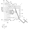
- FIG. 2 is a diagram when the pedal device of the first embodiment is attached to a vehicle.
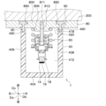
- FIG. 1 is a configuration diagram of a brake-by-wire system using a pedal device. A side view of the pedal device. A cross-sectional view of the pedal device.
- FIG. 4 is a sectional view taken along the line V-V in FIG. 4. An enlarged view of the VI section in FIG. 4.
- FIG. 4 is an enlarged view of section VII.
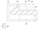
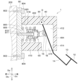
- FIG. 6 is a cross-sectional view showing a modification of the first housing extension and the second housing extension of the pedal device.
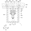
- FIG. 3 is a sectional view of a pedal device according to a second embodiment.
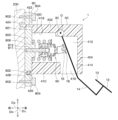
- FIG. 3 is a sectional view of a pedal device according to a third embodiment.
- FIG. 3 is a sectional view showing rotation of the housing of the pedal device.
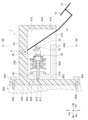
- FIG. 4 is a sectional view of a pedal device according to a fourth embodiment.
- FIG. 5 is a sectional view of a pedal device according to a fifth embodiment.
- FIG. 6 is a sectional view of a pedal device according to a sixth embodiment.
- FIG. 7 is a sectional view of a pedal device according to a seventh embodiment.
- FIG. 7 is a sectional view of a pedal device according to an eighth embodiment.
- FIG. 3 is a cross-sectional view showing rotation of the support member of the pedal device.
- FIG. 9 is a sectional view of a pedal device according to a ninth embodiment.
- FIG. 7 is a sectional view of a pedal device according to an eleventh embodiment.
- FIG. 7 is a sectional view of a pedal device according to a twelfth embodiment.
- FIG. 7 is a sectional view of a pedal device according to a thirteenth embodiment.
- FIG. 7 is a sectional view of a pedal device according to a fifteenth embodiment.
- FIG. 12 is a sectional view of a pedal device according to a sixteenth embodiment.
- FIG. 7 is a sectional view of a pedal device according to a seventeenth embodiment.
- FIG. 29 is a sectional view taken along the line XXX-XXX in FIG. 29.
- FIG. 7 is a sectional view of a pedal device according to an eighteenth embodiment.
- the pedal device 1 of this embodiment is used, for example, as a brake pedal in a brake-by-wire system 150 that controls the brakes of the vehicle 6 shown in FIG. First, this brake-by-wire system 150 will be explained.
- the brake-by-wire system 150 includes wheel cylinders 131 to 134, an ECU 110, a brake circuit 120, and a pedal device 1, as shown in FIG.
- the wheel cylinders 131 to 134 are arranged at each wheel of the vehicle 6, respectively. Furthermore, brake pads (not shown) are attached to each of the wheel cylinders 131 to 134.
- the ECU 110 includes a first ECU 111 and a second ECU 112.
- the first ECU 111 includes a microcomputer, a drive circuit, etc. (not shown). Further, the first ECU 111 controls a first brake circuit 121 of a brake circuit 120, which will be described later, based on a signal from the pedal device 1, which will be described later.
- the second ECU 112 includes a microcomputer, a drive circuit, etc. (not shown). Further, the second ECU 112 controls a second brake circuit 122 of a brake circuit 120, which will be described later, based on a signal from the pedal device 1, which will be described later.
- the brake circuit 120 has a first brake circuit 121 and a second brake circuit 122.
- the first brake circuit 121 includes a reservoir 124, a motor 123, a gear mechanism 125, and a master cylinder 126. Reservoir 124 stores brake fluid. Motor 123 drives gear mechanism 125. The gear mechanism 125 reciprocates a master piston 127 included in the master cylinder 126 in the axial direction of the master cylinder 126.
- the second brake circuit 122 includes a solenoid valve (not shown) and the like. Further, the second brake circuit 122 controls the hydraulic pressure of each wheel cylinder 131 to 134 by opening and closing a solenoid valve in response to a control signal from the second ECU 112.
- the longitudinal direction of the vehicle 6 is assumed to be the vehicle longitudinal direction Da.
- the vertical direction of the vehicle 6 is defined as a vehicle vertical direction Db.
- the left-right direction of the vehicle 6 is defined as a vehicle left-right direction Dc.
- the front in the vehicle longitudinal direction Da is described as the vehicle front.
- the rear in the vehicle longitudinal direction Da is referred to as the vehicle rear.
- the upper part in the vehicle vertical direction Db is referred to as the upper part of the vehicle.
- the downward direction in the vehicle vertical direction Db is referred to as the vehicle downward direction.
- the left side in the vehicle left-right direction Dc is referred to as the vehicle left side.
- the right side in the vehicle left-right direction Dc is referred to as the right side of the vehicle.
- the pedal device 1 includes a pedal 10, a stroke sensor 30, a housing 40, a reaction force generating mechanism 60, and a support member 80.
- the pedal 10 is operated by being stepped on by the driver of the vehicle 6.
- the pedal 10 includes a pedal portion 12, a lever portion 14, a lever protrusion 16, and a lever collar portion 18.
- the pedal section 12 is stepped on by the driver, as shown in FIGS. 3, 4, and 9.
- the lever section 14 is connected to the pedal section 12. Further, as shown in FIGS. 3 to 5 and 9, the lever section 14 rotates around the rotation axis O when the pedal section 12 is stepped on by the driver.
- the lever convex portion 16 is connected to the vehicle front side of the lever portion 14, and protrudes toward the vehicle front from the boundary with the lever portion 14. ing.
- the lever flange 18 is connected to the lever protrusion 16 and protrudes from the boundary with the lever protrusion 16 in a direction perpendicular to the direction in which the lever protrusion 16 projects.
- the stroke sensor 30 is arranged, for example, on the rotation axis O of the lever portion 14. Further, the stroke sensor 30 includes a magnet, a yoke, a Hall element, and the like. Thereby, the stroke sensor 30 detects the rotation angle and stroke amount of the pedal 10 by detecting the rotation angle of the lever portion 14. Further, the stroke sensor 30 outputs signals corresponding to the detected rotation angle and stroke amount of the pedal 10 to the first ECU 111 and the second ECU 112. Note that the stroke sensor 30 has a Hall element to detect the rotation angle and stroke amount of the pedal 10, but is not limited to this, and has an MR element etc. to detect the rotation angle and stroke amount of the pedal 10. May be detected. MR is an abbreviation for Magneto Resistive. Further, the stroke amount is, for example, the amount of movement of the pedal portion 12 in the vehicle longitudinal direction Da.
- the housing 40 supports the pedal 10 so that the pedal 10 can rotate. Furthermore, the housing 40 is formed into a cylindrical shape with a bottom, thereby accommodating a portion of the lever portion 14, a stroke sensor 30, and a reaction force generating mechanism 60, which will be described later. Specifically, as shown in FIGS. 2 to 7 and 9, the housing 40 includes a lever support portion 402, a rear wall 404, a left wall 406, a right wall 408, a lower wall 410, a housing space 412, and a pedal opening. 414 and an opening space 416 for a pedal. The housing 40 also includes a mechanism opening 418, a mechanism opening space 420, a first housing extension 422, a first housing claw 424, a second housing extension 426, and a second housing claw 428.
- the lever support portion 402 extends in the vehicle longitudinal direction Da and the vehicle lateral direction Dc. Further, the rotation axis O of the lever portion 14 and the stroke sensor 30 are attached to the lever support portion 402 . Further, the lever support section 402 supports a part of the lever section 14 so that the lever section 14 can rotate around the rotation axis O, and also supports the stroke sensor 30.
- the rear wall 404 is a wall on the vehicle rear side of the housing 40, as shown in FIGS. 4, 5, and 9. Further, the rear wall 404 is connected to a portion of the lever support portion 402 on the rear side of the vehicle.
- the left side wall 406 is the wall on the left side of the vehicle in the housing 40, as shown in FIG. Further, the left side wall 406 is connected to a portion of the lever support portion 402 on the left side of the vehicle. Further, the left side wall 406 is connected to a portion of the rear wall 404 on the left side of the vehicle.
- the right side wall 408 is the wall on the vehicle right side of the housing 40. Further, the right side wall 408 is connected to a portion of the lever support portion 402 on the right side of the vehicle. Further, the right side wall 408 is connected to a portion of the rear wall 404 on the right side of the vehicle.
- the lower wall 410 is a wall of the housing 40 on the lower side of the vehicle, as shown in FIGS. 4 and 9. Further, the lower wall 410 is connected to a portion of the left side wall 406 on the lower side of the vehicle. Further, the lower wall 410 is connected to a portion of the right side wall 408 on the lower side of the vehicle.
- the housing space 412 is a space defined by the lever support portion 402, the rear wall 404, the left wall 406, the right wall 408, and the lower wall 410, as shown in FIGS. 4, 5, and 9.
- the pedal opening 414 is located at an end of the rear wall 404 on the lower side of the vehicle, an end of the left wall 406 on the lower side of the vehicle, and an end of the right side wall 408 on the lower side of the vehicle.
- the end portion and the lower wall 410 the end portion is located on the rear side of the vehicle.
- the pedal opening space 416 is formed by the pedal opening 414. Further, the pedal opening space 416 communicates with the housing space 412 in the vehicle vertical direction Db, and communicates with the external space of the housing 40 in the vehicle vertical direction Db. Further, a part of the lever portion 14 is inserted into the pedal opening space 416.
- the mechanism opening 418 is located at the end of the lever support portion 402 on the vehicle front side, the end of the left side wall 406 on the vehicle front side, and the right side wall 408 at the end on the vehicle front side. It is comprised of the end on the vehicle front side and the end of the lower wall 410 on the vehicle front side. Therefore, the mechanism opening 418 opens toward the front of the vehicle.
- the mechanism opening space 420 is formed by the mechanism opening 418. Further, the mechanism opening space 420 communicates with the housing space 412 in the vehicle longitudinal direction Da. Further, the mechanism opening space 420 is a space for housing a reaction force generating mechanism 60, which will be described later, in the housing space 412.
- the first housing extension part 422, the first housing claw part 424, the second housing extension part 426, and the second housing claw part 428 constitute a snap fit.
- the first housing extension portion 422 is located at the end of the mechanism opening 418 on the vehicle front side and the vehicle upper side, in this case, the lever support portion. 402 is connected to the end on the vehicle front side. Further, the first housing extension portion 422 extends in the vehicle front direction from the end of the lever support portion 402 on the vehicle front side.
- the first housing claw portion 424 is connected to the side of the first housing extension portion 422 opposite to the lever support portion 402. Further, the first housing claw portion 424 extends from the first housing extension portion 422 in a direction intersecting the direction in which the first housing extension portion 422 extends. For example, the first housing claw portion 424 extends upward from the first housing extension portion 422 in the vehicle upward direction.
- the second housing extension 426 is the end of the mechanism opening 418 on the vehicle front side and the vehicle lower side, in this case, the end of the lower wall 410 on the vehicle front side. connected to the end of the Further, the second housing extension portion 426 extends in the vehicle front direction from the end of the lower wall 410 on the vehicle front side.
- the second housing claw portion 428 is connected to the second housing extension portion 426 on the side opposite to the lower wall 410. Further, the second housing claw portion 428 extends from the second housing extension portion 426 in a direction crossing the direction in which the second housing extension portion 426 extends. For example, the second housing claw portion 428 extends downward from the second housing extension portion 426.
- the reaction force generating mechanism 60 generates a reaction force against the driver's pedal force applied to the pedal section 12.
- the reaction force generation mechanism 60 includes a first holder 61, a second holder 62, a guide member 63, a first elastic member 71, a second elastic member 72, and a third elastic member 73. has.
- the first holder 61 is made of resin, for example. Further, the first holder 61 includes a first support portion 610, a holder convex portion 612, and a first guide portion 614. Although the first holder 61 is made of resin, it is not limited thereto, and may be made of metal, for example.
- the first support portion 610 is, for example, formed in a plate shape extending in a direction perpendicular to the vehicle longitudinal direction Da.
- the holder convex portion 612 is connected to the first support portion 610 and protrudes from the first support portion 610 toward the rear of the vehicle.
- the first guide portion 614 is, for example, formed in a cylindrical shape extending toward the front of the vehicle from the side of the first support portion 610 opposite to the holder convex portion 612.
- the second holder 62 is made of resin, for example. Further, the second holder 62 includes a second support section 620, a second guide section 622, a third guide section 623, and a third support section 626. Although the second holder 62 is made of resin, it is not limited thereto, and may be made of metal, for example.
- the second support portion 620 is formed in a plate shape extending in a direction perpendicular to the vehicle longitudinal direction Da, and is also formed in an annular shape.
- the second guide portion 622 is connected to the outside of the second support portion 620 in a direction perpendicular to the vehicle longitudinal direction Da, and has a cylindrical shape extending from the boundary with the second support portion 620 toward the rear of the vehicle. It is formed. Furthermore, a part of the first guide section 614 is inserted into the hole of the second guide section 622 . Thereby, movement of the first guide part 614 and the second guide part 622 in the vehicle vertical direction Db is mutually restricted. Furthermore, since the first guide portion 614 and the second guide portion 622 extend in the vehicle longitudinal direction Da, the outer surface of the first guide portion 614 and the inner surface of the second guide portion 622 are aligned along the vehicle longitudinal direction Da. Sliding.
- the third guide portion 623 is a bottomed cylinder that is connected to the inside of the second support portion 620 in a direction orthogonal to the vehicle longitudinal direction Da and extends from the boundary with the second support portion 620 toward the rear of the vehicle. It is formed in the shape of
- the third support portion 626 is formed in a plate shape extending in a direction perpendicular to the vehicle longitudinal direction Da, and is also formed in an annular shape. Further, the third support portion 626 is connected to the side of the second guide portion 622 opposite to the second support portion 620, and is therefore disposed on the vehicle rear side with respect to the second support portion 620. Furthermore, a part of the first guide part 614 is inserted into the hole of the third support part 626.
- the guide member 63 is made of metal, for example. Further, the guide member 63 is formed in a cylindrical shape extending in the vehicle longitudinal direction Da. Furthermore, a part of the guide member 63 is inserted into the hole of the second support part 620 and the hole of the third guide part 623. Thereby, the movement of the third guide portion 623 and the guide member 63 in the vehicle vertical direction Db is mutually restricted. Further, since the third guide portion 623 and the guide member 63 extend in the vehicle longitudinal direction Da, the inner surface of the third guide portion 623 and the outer surface of the guide member 63 slide along the vehicle longitudinal direction Da.
- the first elastic member 71, the second elastic member 72, and the third elastic member 73 are arranged in series here.
- the first elastic member 71 is, for example, a coil spring, and is elastically deformed in the vehicle longitudinal direction Da.
- a third guide portion 623 is arranged inside the first elastic member 71. This restricts the movement of the first elastic member 71 in the vehicle vertical direction Db.
- the first elastic member 71 is supported by the first support part 610 and the second support part 620 by being in contact with the first support part 610 and the second support part 620. Further, when the pedal portion 12 is not depressed by the driver, the first elastic member 71 is elastically deformed, and is compressed here.
- the first elastic member 71 when the pedal portion 12 is not depressed by the driver, the first elastic member 71 is elastically deformed, but the present invention is not limited to this, and the first elastic member 71 may not be elastically deformed. In this case, the length of the first elastic member 71 is a free length.
- the second elastic member 72 is, for example, a coil spring, and is elastically deformed in the vehicle longitudinal direction Da. Further, the second elastic member 72 is supported by the second support portion 620 and the support member 80, which will be described later, by being in contact with the third support portion 626 and the support member 80, which will be described later. Further, inside the second elastic member 72, a second support section 620, a second guide section 622, and a support member 80, which will be described later, are arranged. This restricts movement of the second elastic member 72 in the vehicle vertical direction Db. Further, when the second elastic member 72 is projected toward the first elastic member 71 in the vehicle vertical direction Db, the projected second elastic member 72 and the first elastic member 71 overlap.
- the second elastic member 72 when the pedal portion 12 is not depressed by the driver, the second elastic member 72 is elastically deformed, and is compressed here.
- the second elastic member 72 when the pedal portion 12 is not depressed by the driver, the second elastic member 72 is elastically deformed, but the second elastic member 72 is not limited to this, and may not be elastically deformed. In this case, the length of the second elastic member 72 is a free length.
- the third elastic member 73 is, for example, a coil spring, and is elastically deformed in the vehicle longitudinal direction Da. Furthermore, the third elastic member 73 is supported by the first support section 610 by being in contact with the first support section 610 . Further, a holder convex portion 612 is arranged inside the third elastic member 73. This restricts movement of the third elastic member 73 in the vehicle vertical direction Db. Further, when the pedal portion 12 is not depressed by the driver, a portion of the lever convex portion 16 is inserted inside the third elastic member 73, so that the third elastic member 73 is in contact with. At this time, the third elastic member 73 is elastically deformed and is compressed here.
- the third elastic member 73 when the pedal portion 12 is not depressed by the driver, the third elastic member 73 is elastically deformed, but the present invention is not limited to this, and the third elastic member 73 may not be elastically deformed. In this case, the length of the third elastic member 73 is a free length. Further, the third elastic member 73 and the lever flange 18 are in contact with each other when the pedal portion 12 is not depressed by the driver, but the present invention is not limited to this. When the pedal portion 12 is not stepped on by the driver, the third elastic member 73 and the lever flange 18 may be out of contact because the third elastic member 73 and the lever flange 18 are separated from each other. .
- the support member 80 supports the reaction force generation mechanism 60. Moreover, the support member 80 is attached to the dash panel 200 of the vehicle 6, as shown in FIG. Note that the dash panel 200 is a partition wall that separates the vehicle interior 8 from an exterior 7 such as an engine compartment of the vehicle 6, and is sometimes referred to as a bulkhead. Further, outside the vehicle 7, not only the engine of the vehicle 6 but also, for example, the battery, air conditioner, etc. of the vehicle 6 are arranged.
- the support member 80 includes a support portion 800, a panel hole 802, a panel bolt 804, an elastic member regulating portion 806, a first hole 811 for a guide member, and a guide member. It has a second hole 812, a first member hole 821, and a second member hole 822.
- the support portion 800 is formed of metal, for example, into a plate shape extending in the vehicle vertical direction Db and the vehicle lateral direction Dc. Further, the support portion 800 supports a portion of the second elastic member 72 on the opposite side from the third support portion 626. Note that although the support portion 800 is made of metal, it is not limited thereto. For example, the support portion 800 may be made of resin.
- the panel hole 802 is formed in the support portion 800, as shown in FIG. Furthermore, panel bolts 804 are inserted into the panel holes 802 and the holes in the dash panel 200. Thereby, the support member 80 is attached to the dash panel 200. For this reason, the pedal device 1 is attached to the dash panel 200.
- the elastic member regulating portion 806 is connected to the support portion 800 and protrudes toward the rear of the vehicle from the boundary with the support portion 800. Furthermore, the elastic member regulating portion 806 is arranged inside the second elastic member 72, as shown in FIG. Therefore, movement of the second elastic member 72 in the vehicle vertical direction Db is restricted.
- the first hole 811 for the guide member is formed in the support portion 800, as shown in FIGS. 4, 5, 8, and 9.
- the second guide member hole 812 is formed in the elastic member regulating portion 806 and communicates with the first guide member hole 811 . Further, a part of the guide member 63 is inserted into the first guide member hole 811 and the second guide member hole 812. Thereby, the support member 80 and the guide member 63 are fixed.
- the first member hole 821 is formed in a portion of the support portion 800 on the upper side of the vehicle, as shown in FIGS. 4, 6, and 9. Further, the first member hole 821 is a through hole extending in the vehicle longitudinal direction Da. Note that the first member hole 821 is not limited to being a through hole.
- the first member hole 821 may be, for example, a hole with a bottom. In this case, the first member hole 821 is formed using, for example, a 3D printer.
- the first housing extension portion 422 when the first housing claw portion 424 is inserted into the first member hole 821, the first housing extension portion 422 is elastically deformed. Furthermore, when the support member 80 and the housing 40 are brought closer together, the shape of the first housing extension part 422 returns to its original shape, and the first housing extension part 422 is inserted into the first member hole 821, as shown in FIG. . At this time, the first housing claw portion 424 and the support portion 800 come into contact. As a result, the support portion 800 and the mechanism opening 418 are connected, and the support member 80 and the housing 40 are engaged. Note that a recess corresponding to the shape of the first housing claw portion 424 is formed in the dash panel 200 so that the first housing claw portion 424 and the dash panel 200 do not come into contact with each other.
- the second member hole 822 is formed in a portion of the support portion 800 on the lower side of the vehicle, as shown in FIGS. 4, 7, and 9. Further, the second member hole 822 is a through hole extending in the vehicle longitudinal direction Da. Note that the second member hole 822 is not limited to being a through hole.
- the second member hole 822 may be, for example, a hole with a bottom. In this case, the second member hole 822 is formed using, for example, a 3D printer.
- the second housing claw portion 428 when the second housing claw portion 428 is inserted into the second member hole 822, the second housing extension portion 426 is elastically deformed. Furthermore, when the support member 80 and the housing 40 are brought closer together, as shown in FIG. . At this time, the second housing claw portion 428 and the support portion 800 come into contact. As a result, the support portion 800 and the mechanism opening 418 are connected, and the support member 80 and the housing 40 are engaged. Note that a recess corresponding to the shape of the second housing claw portion 428 is formed in the dash panel 200 so that the second housing claw portion 428 and the dash panel 200 do not come into contact with each other.
- the support part 800 closes the mechanism opening space 420. Further, since the support part 800 and the mechanism opening 418 are connected, the support part 800 closes the mechanism opening space 420. Further, the second elastic member 72 supported by the support portion 800 is inserted into the housing space 412 and the mechanism opening space 420. Thereby, the reaction force generating mechanism 60 is housed in the housing space 412 and is surrounded by the support member 80 and the housing 40.
- the brake-by-wire system 150 is configured as described above. Next, the operation of the pedal device 1 will be explained with reference to FIGS. 4 and 8.
- the second holder 62 moves in the vehicle front direction, so the inner surface of the third guide part 623 slides along the outer surface of the guide member 63 in the vehicle front direction, and the second elastic member 72 It is compressed by being pushed by the support portion 626. Therefore, a reaction force is generated by the restoring force generated when the first elastic member 71, the second elastic member 72, and the third elastic member 73 are compressed. Due to this reaction force, even if the mechanical connection between the pedal 10 and the master cylinder 126 is abolished, the pedal device 1 generates the same reaction as when the pedal is connected to the master cylinder 126, that is, when the reaction force by hydraulic pressure is obtained. You can gain power.
- the stroke sensor 30 detects the rotation angle and stroke amount of the pedal section 12 by detecting the rotation angle of the lever section 14. Further, the stroke sensor 30 outputs the detected rotation angle and stroke amount of the pedal section 12 to the first ECU 111 and the second ECU 112.
- the first ECU 111 rotates the motor 123 by, for example, supplying electric power to the motor 123.
- the gear mechanism 125 is driven, and the master piston 127 moves. Therefore, the hydraulic pressure of the brake fluid supplied from the reservoir 124 to the master cylinder 126 increases. This increased hydraulic pressure is supplied to the second brake circuit 122.
- the second ECU 112 supplies power to a solenoid valve (not shown) of the second brake circuit 122, for example. This opens the solenoid valve of the second brake circuit 122. Therefore, the brake fluid supplied to the second brake circuit 122 is supplied to each wheel cylinder 131-134. Therefore, the brake pads attached to the wheel cylinders 131-134 rub against their corresponding brake discs. Therefore, since each wheel is braked, the vehicle 6 is decelerated.
- the second ECU 112 may perform ABS control, VSC control, collision avoidance control, regeneration coordination control, etc. based on the signal from the stroke sensor 30 and the signal from another electronic control device (not shown).
- ABS is an abbreviation for Anti-lock Braking System.
- VSC is an abbreviation for Vehicle Stability Control.
- the pedal device 1 operates.
- foreign matter is prevented from entering the elastic member.
- suppression of foreign matter intrusion will be explained.
- the pedal is attached to the pedal housing.
- these devices have a spring as an elastic member and a housing for the spring.
- the spring generates a reaction force by elastically deforming when the pedal is stepped on.
- a spring housing supports the spring.
- the spring housing is attached to the outside of the pedal housing, and a portion of the spring is exposed to the outside of the spring housing. Therefore, the spring is exposed to the outside of the device. This makes it easy for foreign substances such as dust and moisture to enter the spring from outside the device. Therefore, the deformation of the spring is likely to be inhibited.
- the pedal device 1 of this embodiment includes the pedal 10, the second elastic member 72 of the reaction force generating mechanism 60, the housing 40, and the support member 80.
- the pedal 10 rotates around the rotation axis O when the driver of the vehicle 6 presses the pedal.
- the second elastic member 72 is deformed by the force from the pedal 10 when the pedal 10 rotates, thereby generating a reaction force against the pedal force of the driver of the vehicle 6 .
- the housing 40 supports the pedal 10 so that the pedal 10 can rotate, and forms a housing space 412.
- the second elastic member 72 is accommodated in the housing space 412.
- the support member 80 supports the second elastic member 72. Note that the driver of the vehicle 6 corresponds to the operator.
- the housing 40 has a mechanism opening 418.
- the mechanism opening 418 forms a mechanism opening space 420.
- the mechanism opening space 420 is a space defined by the mechanism opening 418 opening toward the front of the vehicle. Further, the mechanism opening space 420 communicates with the housing space 412. Furthermore, since the housing 40 and the support member 80 are connected, the support member 80 closes the mechanism opening space 420, so that the second elastic member 72 is surrounded by the housing 40 and the support member 80. . Note that the vehicle front direction corresponds to one direction.
- the exposure of the second elastic member 72 to the outside of the pedal device 1 is suppressed, and the housing 40 and the support member 80 prevent foreign matter from entering from the outside of the pedal device 1 toward the second elastic member 72. Prevented. Therefore, foreign matter is prevented from entering the second elastic member 72.
- reaction force generating mechanism 60 is surrounded by the housing 40 and the support member 80, it becomes difficult for people to tamper with the pedal device 1 or to disassemble the pedal device 1. Therefore, these mischiefs and decompositions are suppressed.
- the first embodiment also provides the effects described below.
- the second elastic member 72 is a coil spring. As a result, the influence of temperature on the elastic coefficient of the second elastic member 72 is relatively small. Further, the second elastic member 72 has relatively high oil resistance, solvent resistance, and chemical resistance. Therefore, the second elastic member 72 is relatively hard to deteriorate, and a stable reaction force is generated.
- the housing 40 is disposed on the vehicle interior 8 side of the dash panel 200.
- the dash panel 200 corresponds to a partition wall that separates the exterior 7 and the interior 8 of the vehicle 6 .
- the mechanism opening 418 opens toward the front of the vehicle. Note that the vehicle front direction corresponds to the direction from the housing 40 toward the dash panel 200.
- the support member 80 is disposed between the housing 40 and the dash panel 200, and the housing 40 and the support member 80 are connected in the vehicle longitudinal direction Da. Thereafter, the pedal device 1 is attached to the dash panel 200 without reversing the pedal device 1, with the posture of the pedal device 1 unchanged. Therefore, it is easy to attach the pedal device 1 to the dash panel 200. Therefore, the pedal device 1 and the dash panel 200 can be easily assembled. Therefore, the cost of assembling the pedal device 1 is reduced.
- the housing 40 includes a first housing extension 422, a first housing claw 424, a second housing extension 426, and a second housing claw 428.
- the first housing extension part 422 and the second housing extension part 426 extend from the mechanism opening 418 in the vehicle front direction.
- the first housing claw portion 424 is connected to the first housing extension portion 422 and extends upward from the first housing extension portion 422 in the vehicle.
- the second housing claw portion 428 is connected to the second housing extension portion 426 and extends downward from the second housing extension portion 426 in the vehicle direction.
- the first housing extension part 422 and the second housing extension part 426 correspond to extension parts.
- the first housing claw portion 424 and the second housing claw portion 428 correspond to claw portions.
- the upward direction of the vehicle and the downward direction of the vehicle correspond to a direction intersecting the direction in which the extension portion extends.
- the support member 80 has a first member hole 821 and a second member hole 822.
- the first housing extension 422 is inserted into the first member hole 821 .
- the second housing extension 426 is inserted into the second member hole 822 .
- the first housing claw portion 424 and the second housing claw portion 428 are in contact with the support member 80, the housing 40 and the support member 80 are engaged with each other. This makes it easier to hold the housing 40 and the support member 80 together.
- the first member hole 821 and the second member hole 822 correspond to a member space.
- the first housing extension part 422 is deformed when the first housing claw part 424 is inserted into the first member hole 821. Additionally, the second housing extension 426 deforms when the second housing claw 428 is inserted into the second member hole 822 .
- the first housing extension part 422 can be easily inserted into the first member hole 821 with one action without using a jig or the like.
- the second housing extension portion 426 can be easily inserted into the second member hole 822 with one action without using a jig or the like. Therefore, the housing 40 and the support member 80 can be easily assembled. Further, since there is no need to use a jig or the like, the cost for assembling the pedal device 1 is reduced.
- the number of parts of the pedal device 1 is reduced. Furthermore, since the number of parts of the pedal device 1 is reduced, the cost of the pedal device 1 is reduced.
- the support member 80 includes a support portion 800 and an elastic member restriction portion 806.
- the support part 800 supports the second elastic member 72.
- the elastic member regulating portion 806 extends from the support portion 800 in the direction in which the second elastic member 72 is deformed. Further, the elastic member regulating section 806 regulates movement of the second elastic member 72 in the vehicle vertical direction Db. Note that the vehicle vertical direction Db corresponds to a direction perpendicular to the deformation direction of the second elastic member 72.
- the support member 80 supports one end of the second elastic member 72.
- the pedal device 1 includes a second holder 62.
- the second holder 62 has a third support section 626 and a second guide section 622.
- the third support portion 626 supports the other end of the second elastic member 72.
- the second guide portion 622 extends from the third support portion 626 in the direction in which the second elastic member 72 is deformed. Further, the second guide portion 622 restricts movement of the second elastic member 72 in the vehicle vertical direction Db.
- the third support section 626 corresponds to a member support section.
- the second guide section 622 corresponds to a member regulating section.
- the shapes of the first housing extension part 422, the first housing claw part 424, the second housing extension part 426, and the second housing claw part 428 are different from the first embodiment. Further, the shapes of the first member hole 821 and the second member hole 822 are different from those of the first embodiment. Other than these, the second embodiment is the same as the first embodiment.
- the first housing extension 422 is connected to the end of the mechanism opening 418 on the vehicle front side and the left side of the vehicle, here, the end of the left side wall 406 on the vehicle front side. Further, the first housing extension portion 422 extends in the vehicle front direction from the end of the left side wall 406 on the vehicle front side. Furthermore, the first housing extension 422 is inserted into a first member hole 821 formed at a position corresponding to the first housing extension 422 .
- the first housing claw portion 424 is connected to the side of the first housing extension portion 422 opposite to the left side wall 406. Further, the first housing claw portion 424 extends from the first housing extension portion 422 toward the left side of the vehicle. Further, the first housing claw portion 424 is in contact with the support portion 800. As a result, the support portion 800 and the mechanism opening 418 are connected, and the support member 80 and the housing 40 are engaged.
- the second housing extension 426 is connected to the end of the mechanism opening 418 on the vehicle front side and the right side of the vehicle, here, the end of the right side wall 408 on the vehicle front side. Further, the second housing extension portion 426 extends in the vehicle front direction from the end of the right side wall 408 on the vehicle front side. Furthermore, the second housing extension 426 is inserted into a second member hole 822 formed at a position corresponding to the second housing extension 426 .
- the second housing claw portion 428 is connected to the side of the second housing extension portion 426 opposite to the right side wall 408. Further, the second housing claw portion 428 extends from the second housing extension portion 426 toward the right side of the vehicle. Further, the second housing claw portion 428 is in contact with the support portion 800. Therefore, the support portion 800 and the mechanism opening 418 are connected, and the support member 80 and the housing 40 are engaged. Furthermore, since the support part 800 and the mechanism opening 418 are connected, the support part 800 closes the mechanism opening space 420. Further, the second elastic member 72 supported by the support portion 800 is inserted into the housing space 412 and the mechanism opening space 420. Thereby, the reaction force generating mechanism 60 is housed in the housing space 412 and is surrounded by the support member 80 and the housing 40.
- the pedal device 1 of the second embodiment is configured.
- This second embodiment also provides the same effects as the first embodiment.
- the second housing claw portion 428 is formed in a cylindrical shape with an axis extending in the vehicle left-right direction Dc. Further, the second housing extension portion 426 and the second housing claw portion 428 are inserted into the second member hole 822 . Furthermore, the second member hole 822 is formed in a shape and size that allows the housing 40 to rotate around the axis of the second housing claw portion 428 .
- the pedal device 1 of the third embodiment is configured.
- This third embodiment also has the same effects as the first embodiment. Furthermore, the third embodiment also provides the effects described below.
- the second housing claw portion 428 is connected to the second housing extension portion 426 and rotates about an axis extending in the vehicle left-right direction Dc. Further, when the second housing claw portion 428 rotates, the housing 40 rotates around the axis of the second housing claw portion 428, and the first housing claw portion 424 is inserted into the first member hole 821.
- the first housing extension portion 422 corresponds to a first extension portion.
- the first housing claw portion 424 corresponds to a first claw portion.
- Second housing extension 426 corresponds to the second extension.
- the second housing claw portion 428 corresponds to a second claw portion.
- the vehicle left-right direction Dc corresponds to a direction orthogonal to one direction.
- the housing 40 has a front wall 430 instead of the right side wall 408.
- the configurations of the housing space 412, the pedal opening 414, the mechanism opening 418, and the mechanism opening space 420 are different from the first embodiment.
- the shapes of the first housing extension 422, the first housing claw 424, the second housing extension 426, and the second housing claw 428 are different from those of the first embodiment.
- the support member 80 further includes a support member extension 830.
- the shapes of the first member hole 821 and the second member hole 822 are different from those of the first embodiment.
- the second embodiment is the same as the first embodiment.
- the front wall 430 is a wall of the housing 40 on the vehicle front side. Further, the front wall 430 is connected to a portion of the lever support portion 402 on the vehicle front side, a portion of the left wall 406 on the vehicle front side, and a portion of the lower wall 410 on the vehicle front side. Note that here, a panel hole 802 is formed in the front wall 430, and the front wall 430 is located closer to the front of the vehicle than the support portion 800 is. Therefore, the panel hole 802 is not formed in the support portion 800. Furthermore, panel bolts 804 are inserted into panel holes 802 in the front wall 430 and holes in the dash panel 200. Thereby, the housing 40 is attached to the dash panel 200. For this reason, the pedal device 1 is attached to the dash panel 200.
- the housing space 412 is a space defined by the lever support portion 402, the rear wall 404, the left side wall 406, the lower wall 410, and the front wall 430.
- the pedal opening 414 is comprised of an end of the rear wall 404 on the vehicle lower side, an end of the left wall 406 on the vehicle lower side, and an end of the lower wall 410 on the vehicle rear side.
- the mechanism opening 418 is located at the end of the lever support part 402 on the right side of the vehicle, the end of the rear wall 404 on the right side of the vehicle, the end of the lower wall 410 on the right side of the vehicle, and the front wall 430. It consists of the right end of the vehicle. Therefore, the mechanism opening 418 opens toward the right side of the vehicle. Note that the vehicle right direction corresponds to one direction.
- the mechanism opening space 420 is formed by the mechanism opening 418 and communicates with the housing space 412 in the vehicle left-right direction Dc.
- the first housing extension 422 is connected to the end of the mechanism opening 418 on the vehicle front side and the right side of the vehicle, here, the end of the front wall 430 on the right side of the vehicle. Further, the first housing extension portion 422 extends from the end of the front wall 430 on the right side of the vehicle in the right direction of the vehicle.
- the first housing claw portion 424 is connected to the side of the first housing extension portion 422 opposite to the front wall 430. Further, the first housing claw portion 424 extends from the first housing extension portion 422 in the vehicle front direction.
- the second housing extension 426 is connected to the end of the mechanism opening 418 on the vehicle rear side and the right side of the vehicle, here, the end of the rear wall 404 on the right side of the vehicle. Further, the second housing extension portion 426 extends from the end of the rear wall 404 on the right side of the vehicle in the right direction of the vehicle.
- the second housing claw portion 428 is connected to the second housing extension portion 426 on the side opposite to the rear wall 404. Further, the second housing claw portion 428 extends from the second housing extension portion 426 toward the rear of the vehicle.
- the support member extension portion 830 is connected to a portion of the support portion 800 on the right side of the vehicle. Further, the support member extension portion 830 is made of metal and has a plate shape extending in the vehicle longitudinal direction Da and the vehicle vertical direction Db. Note that although the support member extension portion 830 is made of metal, it is not limited thereto. For example, support member extension 830 may be formed of resin.
- the first member hole 821 is formed in the support member extension part 830 instead of being formed in the support part 800. Further, the first member hole 821 is a hole extending in the vehicle left-right direction Dc. Furthermore, the first housing extension portion 422 is inserted into the first member hole 821 . Further, the first housing claw portion 424 and the support member extension portion 830 are in contact with each other. As a result, the support member extension 830 and the mechanism opening 418 are connected, and the support member 80 and the housing 40 are engaged.
- the second member hole 822 is formed in the support member extension part 830 instead of being formed in the support part 800. Further, the second member hole 822 is a hole extending in the vehicle left-right direction Dc. Furthermore, the second housing extension 426 is inserted into the second member hole 822 . Further, the second housing claw portion 428 and the support member extension portion 830 are in contact with each other. As a result, the support member extension 830 and the mechanism opening 418 are connected, and the support member 80 and the housing 40 are engaged.
- the support member extension part 830 and the mechanism opening 418 are connected, the support member extension part 830 closes the mechanism opening space 420. Further, the second elastic member 72 supported by the support portion 800 is inserted into the housing space 412. Thereby, the reaction force generating mechanism 60 is housed in the housing space 412 and is surrounded by the support member 80 and the housing 40.
- the pedal device 1 of the fourth embodiment is configured.
- This fourth embodiment also provides the same effects as the first embodiment.
- the housing 40 may have a right side wall 408 instead of the left side wall 406.
- the housing space 412 is a space defined by the lever support portion 402, the rear wall 404, the right side wall 408, the lower wall 410, and the front wall 430.
- the mechanism opening 418 is located at the end of the lever support portion 402 on the left side of the vehicle, the end of the rear wall 404 on the left side of the vehicle, the end of the lower wall 410 on the left side of the vehicle, and the It is constituted by the end portion of the wall 430 on the left side of the vehicle.
- the mechanism opening 418 opens toward the left side of the vehicle.
- the left direction of the vehicle corresponds to one direction.
- the support member extension portion 830 is connected to a portion of the support portion 800 on the left side of the vehicle.
- the first housing extension portion 422 extends from the end of the front wall 430 on the left side of the vehicle in the left direction of the vehicle.
- the second housing extension portion 426 extends from the end of the rear wall 404 on the left side of the vehicle in the left direction of the vehicle. Such a form may be sufficient.
- the housing 40 has a front wall 430 instead of the lower wall 410. Furthermore, instead of the support member 80 having no panel holes 802 and panel bolts 804, the housing 40 has panel holes 802 and panel bolts 804. Furthermore, the configurations of the housing space 412, the mechanism opening 418, and the mechanism opening space 420 are different from those of the first embodiment. Furthermore, the shapes of the first housing extension part 422, the first housing claw part 424, the second housing extension part 426, and the second housing claw part 428 are different from those in the first embodiment. Further, the support member 80 has a support member extension 830. Further, the shapes of the first member hole 821 and the second member hole 822 are different from those of the first embodiment. Other than these, the second embodiment is the same as the first embodiment.
- the front wall 430 is connected to a portion of the lever support portion 402 on the vehicle front side, a portion of the left wall 406 on the vehicle front side, and a portion of the right wall 408 on the vehicle front side. Further, a panel hole 802 is formed in the front wall 430. Panel bolts 804 are inserted into the panel holes 802 and the holes in the dash panel 200. Thereby, the housing 40 is attached to the dash panel 200. For this reason, the pedal device 1 is attached to the dash panel 200.
- the housing space 412 is a space defined by the lever support portion 402, the rear wall 404, the left wall 406, the right wall 408, and the front wall 430.
- the pedal opening 414 is comprised of an end of the rear wall 404 on the vehicle lower side, an end of the left wall 406 on the vehicle lower side, and an end of the right wall 408 on the vehicle lower side.
- the mechanism opening 418 is comprised of an end portion of the left wall 406 on the vehicle lower side, an end portion of the right wall 408 on the vehicle lower side, and a portion of the front wall 430 on the vehicle lower side. Therefore, the mechanism opening 418 opens toward the bottom of the vehicle. Note that the downward direction of the vehicle corresponds to one direction.
- the mechanism opening space 420 is formed by the mechanism opening 418 and communicates with the housing space 412 in the vehicle vertical direction Db.
- the first housing extension 422 is connected to the end of the mechanism opening 418 on the left side of the vehicle, here, the end of the left side wall 406 on the lower side of the vehicle. Further, the first housing extension portion 422 extends downward from the end of the left side wall 406 on the vehicle lower side.
- the first housing claw portion 424 is connected to the side of the first housing extension portion 422 opposite to the left side wall 406. Further, the first housing claw portion 424 extends from the first housing extension portion 422 toward the left side of the vehicle.
- the second housing extension 426 is connected to the end of the mechanism opening 418 on the right side of the vehicle, here, the end of the right side wall 408 on the lower side of the vehicle. Further, the second housing extension portion 426 extends downward from the end of the right side wall 408 on the vehicle lower side.
- the second housing claw portion 428 is connected to the side of the second housing extension portion 426 opposite to the right side wall 408. Further, the second housing claw portion 428 extends from the second housing extension portion 426 toward the right side of the vehicle.
- the support member extension portion 830 is connected to a portion of the support portion 800 on the lower side of the vehicle. Further, the support member extension portion 830 is made of metal and has a plate shape extending in the vehicle longitudinal direction Da and the vehicle lateral direction Dc.
- the first member hole 821 is formed in the support member extension part 830 instead of being formed in the support part 800. Further, the first member hole 821 is a hole extending in the vehicle vertical direction Db. Furthermore, the first housing extension portion 422 is inserted into the first member hole 821 . Further, the first housing claw portion 424 and the support member extension portion 830 are in contact with each other. As a result, the support member extension 830 and the mechanism opening 418 are connected, and the support member 80 and the housing 40 are engaged.
- the second member hole 822 is formed in the support member extension part 830 instead of being formed in the support part 800. Further, the second member hole 822 is a hole extending in the vehicle vertical direction Db. Furthermore, the second housing extension 426 is inserted into the second member hole 822 . Further, the second housing claw portion 428 and the support member extension portion 830 are in contact with each other. As a result, the support member extension 830 and the mechanism opening 418 are connected, and the support member 80 and the housing 40 are engaged.
- the support member extension part 830 and the mechanism opening 418 are connected, the support member extension part 830 closes the mechanism opening space 420. Further, the second elastic member 72 supported by the support portion 800 is inserted into the housing space 412. Thereby, the reaction force generating mechanism 60 is housed in the housing space 412 and is surrounded by the support member 80 and the housing 40.
- the pedal device 1 of the fifth embodiment is configured.
- This fifth embodiment also has the same effects as the first embodiment.
- the support member 80 includes a first member extension part 841, a first member claw part 851, a second member claw part 851, and a first member claw part 851, instead of the first member hole 821 and the second member hole 822. It has an extension part 842 and a second member claw part 852. Furthermore, the housing 40 does not include the first housing extension 422, the first housing claw 424, the second housing extension 426, and the second housing claw 428. Instead, the housing 40 has a first housing hole 431, a second housing hole 432, a third housing hole 433, and a fourth housing hole 434. Other than these, the second embodiment is the same as the first embodiment.
- the first member extension portion 841, the first member claw portion 851, the second member extension portion 842, and the second member claw portion 852 constitute a snap fit.
- the first member extension portion 841 is connected to a portion of the support portion 800 on the vehicle upper side. Further, the first member extension portion 841 extends from a portion of the support portion 800 on the upper side of the vehicle toward the rear of the vehicle.
- the first member claw portion 851 is connected to the side of the first member extension portion 841 opposite to the support portion 800. Further, the first member claw portion 851 extends from the first member extension portion 841 in a direction crossing the direction in which the first member extension portion 841 extends. For example, the first member claw portion 851 extends upward from the first member extension portion 841 in the vehicle upward direction.
- the second member extension portion 842 is connected to a portion of the support portion 800 on the lower side of the vehicle. Further, the second member extension portion 842 extends from a portion of the support portion 800 on the lower side of the vehicle toward the rear of the vehicle.
- the second member claw portion 852 is connected to the side of the second member extension portion 842 opposite to the support portion 800. Further, the second member claw portion 852 extends from the second member extension portion 842 in a direction intersecting the direction in which the second member extension portion 842 extends. For example, the second member claw portion 852 extends downward from the second member extension portion 842 in the vehicle downward direction.
- a first housing hole 431 and a second housing hole 432 are formed in the lever support portion 402. Further, the first housing hole 431 is a hole extending in the vehicle longitudinal direction Da. The second housing hole 432 communicates with the first housing hole 431. Furthermore, the second housing hole 432 is a through hole extending in the vehicle vertical direction Db. Note that the second housing hole 432 is not limited to being a through hole. The second housing hole 432 may be, for example, a bottomed hole.
- the first member extension portion 841 when the first member claw portion 851 is inserted into the first housing hole 431, the first member extension portion 841 is elastically deformed. Furthermore, when the support member 80 and the housing 40 are brought closer together, the shape of the first member extension part 841 returns to its original shape, and the first member extension part 841 is inserted into the first housing hole 431. At this time, the first member claw portion 851 is inserted into the second housing hole 432, and the first member claw portion 851 and the lever support portion 402 come into contact. As a result, the support portion 800 and the mechanism opening 418 are connected, and the support member 80 and the housing 40 are engaged.
- a third housing hole 433 and a fourth housing hole 434 are formed in the lower wall 410. Further, the third housing hole 433 is a hole extending in the vehicle longitudinal direction Da. The fourth housing hole 434 communicates with the third housing hole 433. Further, the fourth housing hole 434 is a through hole extending in the vehicle vertical direction Db. Note that the fourth housing hole 434 is not limited to being a through hole. The fourth housing hole 434 may be a bottomed hole, for example.
- the second member claw portion 852 when the second member claw portion 852 is inserted into the third housing hole 433, the second member extension portion 842 is elastically deformed. Furthermore, when the support member 80 and the housing 40 are brought closer together, the shape of the second member extension part 842 returns to its original shape, and the second member extension part 842 is inserted into the third housing hole 433. At this time, the second member claw portion 852 is inserted into the fourth housing hole 434, and the second member claw portion 852 and the lower wall 410 come into contact. As a result, the support portion 800 and the mechanism opening 418 are connected, and the support member 80 and the housing 40 are engaged.
- the support part 800 closes the mechanism opening space 420. Further, since the support part 800 and the mechanism opening 418 are connected, the support part 800 closes the mechanism opening space 420. Further, the second elastic member 72 supported by the support portion 800 is inserted into the housing space 412 and the mechanism opening space 420. Thereby, the reaction force generating mechanism 60 is housed in the housing space 412 and is surrounded by the support member 80 and the housing 40.
- the pedal device 1 of the sixth embodiment is configured.
- This sixth embodiment also provides the same effects as the first embodiment. Furthermore, the sixth embodiment also provides the effects described below.
- the support member 80 includes a support portion 800, a first member extension portion 841, a first member claw portion 851, a second member extension portion 842, and a second member claw portion 852.
- the support part 800 supports the second elastic member 72.
- the first member extension portion 841 extends from the support portion 800 toward the rear of the vehicle.
- the first member claw portion 851 is connected to the first member extension portion 841 and extends upward from the first member extension portion 841 in the vehicle upward direction.
- the second member extension portion 842 extends from the support portion 800 toward the rear of the vehicle.
- the second member claw portion 852 is connected to the second member extension portion 842 and extends downward from the second member extension portion 842 in the vehicle downward direction.
- first member extension part 841 and the second member extension part 842 correspond to extension parts.
- the first member claw portion 851 and the second member claw portion 852 correspond to claw portions.
- the vehicle rear direction corresponds to the opposite direction to the one direction.
- the upward direction of the vehicle and the downward direction of the vehicle correspond to a direction intersecting the direction in which the extension portion extends.
- the housing 40 has a first housing hole 431, a second housing hole 432, a third housing hole 433, and a fourth housing hole 434.
- a first member extension 841 is inserted into the first housing hole 431 .
- the first member claw portion 851 is inserted into the second housing hole 432 .
- a second member extension 842 is inserted into the third housing hole 433 .
- a second member claw portion 852 is inserted into the fourth housing hole 434 .
- the housing 40 and the support member 80 are engaged with each other. This makes it easier to hold the housing 40 and the support member 80 together.
- the first housing hole 431 and the third housing hole 433 correspond to the first space.
- the second housing hole 432 and the fourth housing hole 434 correspond to the second space.
- the first member extension portion 841 is deformed when the first member claw portion 851 is inserted into the first housing hole 431. Additionally, the second member extension portion 842 deforms when the second member claw portion 852 is inserted into the second housing hole 432 .
- the number of parts of the pedal device 1 is reduced. Furthermore, since the number of parts of the pedal device 1 is reduced, the cost of the pedal device 1 is reduced.
- the first housing hole 431 and the second housing hole 432 are formed in the left side wall 406. Further, the second housing hole 432 extends in the vehicle left-right direction Dc instead of extending in the vehicle up-down direction Db.
- a third housing hole 433 and a fourth housing hole 434 are formed in the right side wall 408. Moreover, the fourth housing hole 434 extends in the vehicle left-right direction Dc instead of extending in the vehicle up-down direction Db.
- the first member extension portion 841 is connected to a portion of the support portion 800 on the left side of the vehicle. Further, the first member extension portion 841 extends from a portion of the support portion 800 on the left side of the vehicle toward the rear of the vehicle. Further, the first member extension 841 is inserted into the first housing hole 431.
- the first member claw portion 851 extends from the first member extension portion 841 toward the left side of the vehicle. Further, the first member claw portion 851 is inserted into the second housing hole 432 and is in contact with the left side wall 406. As a result, the support portion 800 and the mechanism opening 418 are connected, and the support member 80 and the housing 40 are engaged.
- the second member extension portion 842 is connected to a portion of the support portion 800 on the right side of the vehicle. Further, the second member extension portion 842 extends from a portion of the support portion 800 on the right side of the vehicle toward the rear of the vehicle. Further, the second member extension 842 is inserted into the third housing hole 433.
- the second member claw portion 852 extends from the second member extension portion 842 toward the right of the vehicle. Further, the second member claw portion 852 is inserted into the fourth housing hole 434 and is in contact with the right side wall 408. Therefore, the support portion 800 and the mechanism opening 418 are connected, and the support member 80 and the housing 40 are engaged. Furthermore, since the support part 800 and the mechanism opening 418 are connected, the support part 800 closes the mechanism opening space 420. Further, the second elastic member 72 supported by the support portion 800 is inserted into the housing space 412 and the mechanism opening space 420. Thereby, the reaction force generating mechanism 60 is housed in the housing space 412 and is surrounded by the support member 80 and the housing 40.
- the pedal device 1 of the seventh embodiment is configured.
- This seventh embodiment also provides the same effects as the sixth embodiment.
- the housing 40 does not have the third housing hole 433 and the fourth housing hole 434. Further, the form of the second member claw portion 852 is different from the sixth embodiment. Other than these, this embodiment is the same as the sixth embodiment.
- the second member claw portion 852 is formed in a cylindrical shape with an axis extending in the vehicle left-right direction Dc. Further, a portion of the second member claw portion 852 is inserted into a hole (not shown) formed in the left side wall 406 and a hole (not shown) formed in the right side wall 408. Further, the second member claw portion 852 is rotatably supported by the left side wall 406 and the right side wall 408 about an axis extending in the vehicle left-right direction Dc.
- the pedal device 1 of the eighth embodiment is configured.
- This eighth embodiment also provides the same effects as the sixth embodiment. Furthermore, the eighth embodiment also provides the effects described below.
- the second member claw portion 852 is connected to the second member extension portion 842 and rotates about an axis extending in the vehicle left-right direction Dc. Further, when the second member claw portion 852 rotates, the support member 80 rotates around the axis of the second member claw portion 852, so that the first member claw portion 851 is inserted into the first member hole 821.
- the first member extension portion 841 corresponds to a first extension portion.
- the first member claw portion 851 corresponds to the first claw portion.
- the second member extension 842 corresponds to a second extension.
- the second member claw portion 852 corresponds to a second claw portion.
- the vehicle left-right direction Dc corresponds to a direction orthogonal to one direction.
- the housing 40 has a front wall 430 instead of the right side wall 408. Further, the configurations of the housing space 412, the pedal opening 414, the mechanism opening 418, and the mechanism opening space 420 are different from those of the sixth embodiment. Furthermore, support member 80 further includes a support member extension 830. Further, the shapes of the first housing hole 431, the second housing hole 432, the third housing hole 433, and the fourth housing hole 434 are different from those in the sixth embodiment. Furthermore, the forms of the first member extension part 841, the first member claw part 851, the second member extension part 842, and the second member claw part 852 are different from those in the sixth embodiment. Other than these, this embodiment is the same as the sixth embodiment.
- the front wall 430 is connected to a portion of the lever support portion 402 on the vehicle front side, a portion of the left wall 406 on the vehicle front side, and a portion of the lower wall 410 on the vehicle front side.
- a panel hole 802 is formed in the front wall 430, and the front wall 430 is located closer to the front of the vehicle than the support portion 800 is. Therefore, the panel hole 802 is not formed in the support portion 800.
- panel bolts 804 are inserted into panel holes 802 in the front wall 430 and holes in the dash panel 200. Thereby, the housing 40 is attached to the dash panel 200. For this reason, the pedal device 1 is attached to the dash panel 200.
- the housing space 412 is a space defined by the lever support portion 402, the rear wall 404, the left side wall 406, the lower wall 410, and the front wall 430.
- the pedal opening 414 is comprised of an end of the rear wall 404 on the vehicle lower side, an end of the left wall 406 on the vehicle lower side, and an end of the lower wall 410 on the vehicle rear side.
- the mechanism opening 418 is located at the end of the lever support part 402 on the right side of the vehicle, the end of the rear wall 404 on the right side of the vehicle, the end of the lower wall 410 on the right side of the vehicle, and the front wall 430. It consists of the right end of the vehicle. Therefore, the mechanism opening 418 opens toward the right side of the vehicle. Note that the vehicle right direction corresponds to one direction.
- the mechanism opening space 420 is formed by the mechanism opening 418 and communicates with the housing space 412 in the vehicle left-right direction Dc.
- the support member extension portion 830 is connected to a portion of the support portion 800 on the right side of the vehicle. Further, the support member extension portion 830 is made of metal and has a plate shape extending in the vehicle longitudinal direction Da and the vehicle vertical direction Db.
- the first housing hole 431 and the second housing hole 432 are formed in a portion of the front wall 430 on the right side of the vehicle. Further, the first housing hole 431 extends in the vehicle left-right direction Dc. The second housing hole 432 communicates with the first housing hole 431 and extends in the vehicle longitudinal direction Da.
- the third housing hole 433 and the fourth housing hole 434 are formed in a portion of the rear wall 404 on the right side of the vehicle. Further, the third housing hole 433 extends in the vehicle left-right direction Dc. The fourth housing hole 434 communicates with the third housing hole 433 and extends in the vehicle longitudinal direction Da.
- the first member extension portion 841 is connected to a portion of the support member extension portion 830 on the vehicle front side. Further, the first member extension portion 841 extends in the left direction of the vehicle from a portion of the support member extension portion 830 on the vehicle front side. Further, the first member extension 841 is inserted into the first housing hole 431. Note that the vehicle left direction corresponds to the opposite direction to one direction.
- the first member claw portion 851 extends from the first member extension portion 841 in the vehicle front direction. Further, the first member claw portion 851 is inserted into the second housing hole 432 and is in contact with the front wall 430. As a result, the support member extension 830 and the mechanism opening 418 are connected, and the support member 80 and the housing 40 are engaged.
- the second member extension portion 842 is connected to a portion of the support member extension portion 830 on the vehicle rear side. Further, the second member extension portion 842 extends in the left direction of the vehicle from a portion of the support member extension portion 830 on the vehicle rear side. Further, the second member extension 842 is inserted into the third housing hole 433.
- the second member claw portion 852 extends from the second member extension portion 842 toward the rear of the vehicle. Further, the second member claw portion 852 is inserted into the fourth housing hole 434 and is in contact with the rear wall 404. Therefore, the support member extension 830 and the mechanism opening 418 are connected, and the support member 80 and the housing 40 are engaged. Furthermore, since the support member extension part 830 and the mechanism opening 418 are connected, the support member extension part 830 closes the mechanism opening space 420. Further, the second elastic member 72 supported by the support portion 800 is inserted into the housing space 412. Thereby, the reaction force generating mechanism 60 is housed in the housing space 412 and is surrounded by the support member 80 and the housing 40.
- the pedal device 1 of the ninth embodiment is configured.
- This ninth embodiment also provides the same effects as the sixth embodiment.
- the housing 40 may have a right side wall 408 instead of the left side wall 406.
- the housing space 412 is a space defined by the lever support portion 402, the rear wall 404, the right side wall 408, the lower wall 410, and the front wall 430.
- the mechanism opening 418 is located at the end of the lever support portion 402 on the left side of the vehicle, the end of the rear wall 404 on the left side of the vehicle, the end of the lower wall 410 on the left side of the vehicle, and the It is constituted by the end portion of the wall 430 on the left side of the vehicle.
- the mechanism opening 418 opens toward the left side of the vehicle.
- the left direction of the vehicle corresponds to one direction.
- the support member extension portion 830 is connected to a portion of the support portion 800 on the left side of the vehicle.
- the first housing hole 431 and the second housing hole 432 are formed in a portion of the front wall 430 on the left side of the vehicle.
- the third housing hole 433 and the fourth housing hole 434 are formed in a portion of the rear wall 404 on the left side of the vehicle.
- the first member extension portion 841 extends from a portion of the support member extension portion 830 on the vehicle front side toward the right side of the vehicle.
- the second member extension portion 842 extends from a portion of the support member extension portion 830 on the vehicle rear side toward the right side of the vehicle.
- the vehicle right direction corresponds to the opposite direction to the one direction. Such a form may be sufficient.
- the housing 40 has a front wall 430 instead of the lower wall 410. Furthermore, instead of the support member 80 having no panel holes 802 and panel bolts 804, the housing 40 has panel holes 802 and panel bolts 804. Furthermore, the configurations of the housing space 412, the mechanism opening 418, and the mechanism opening space 420 are different from those in the sixth embodiment.
- the support member 80 further includes a support member extension 830. Furthermore, the shapes of the first housing hole 431, the second housing hole 432, the third housing hole 433, and the fourth housing hole 434 are different from those in the sixth embodiment. Further, the forms of the first member extension portion 841, the first member claw portion 851, the second member extension portion 842, and the second member claw portion 852 are different from those in the sixth embodiment. Other than these, this embodiment is the same as the sixth embodiment.
- the front wall 430 is connected to a portion of the lever support portion 402 on the vehicle front side, a portion of the left wall 406 on the vehicle front side, and a portion of the right wall 408 on the vehicle front side. Further, a panel hole 802 is formed in the front wall 430. Panel bolts 804 are inserted into the panel holes 802 and the holes in the dash panel 200. Thereby, the housing 40 is attached to the dash panel 200. For this reason, the pedal device 1 is attached to the dash panel 200.
- the housing space 412 is a space defined by the lever support portion 402, the rear wall 404, the left wall 406, the right wall 408, and the front wall 430.
- the pedal opening 414 is comprised of an end of the rear wall 404 on the vehicle lower side, an end of the left wall 406 on the vehicle lower side, and an end of the right wall 408 on the vehicle lower side.
- the mechanism opening 418 is comprised of an end of the left wall 406 on the vehicle lower side, an end of the right wall 408 on the vehicle lower side, and a portion of the front wall 430 on the vehicle lower side. Therefore, the mechanism opening 418 opens toward the bottom of the vehicle. Note that the downward direction of the vehicle corresponds to one direction.
- the mechanism opening space 420 is formed by the mechanism opening 418 and communicates with the housing space 412 in the vehicle vertical direction Db.
- the support member extension portion 830 is connected to a portion of the support portion 800 on the lower side of the vehicle. Further, the support member extension portion 830 is made of metal and has a plate shape extending in the vehicle longitudinal direction Da and the vehicle lateral direction Dc.
- the first housing hole 431 and the second housing hole 432 are formed in a portion of the left side wall 406 on the lower side of the vehicle. Further, the first housing hole 431 extends in the vehicle vertical direction Db. The second housing hole 432 communicates with the first housing hole 431 and extends in the vehicle left-right direction Dc.
- the third housing hole 433 and the fourth housing hole 434 are formed in a portion of the right side wall 408 on the lower side of the vehicle. Further, the third housing hole 433 extends in the vehicle vertical direction Db. The fourth housing hole 434 communicates with the third housing hole 433 and extends in the vehicle left-right direction Dc.
- the first member extension portion 841 is connected to a portion of the support member extension portion 830 on the left side of the vehicle. Further, the first member extension portion 841 extends upwardly from the portion of the support member extension portion 830 on the left side of the vehicle. Further, the first member extension 841 is inserted into the first housing hole 431. Note that the upward direction of the vehicle corresponds to the opposite direction to the one direction.
- the first member claw portion 851 extends from the first member extension portion 841 toward the left side of the vehicle. Further, the first member claw portion 851 is inserted into the second housing hole 432 and is in contact with the left side wall 406. As a result, the support member extension 830 and the mechanism opening 418 are connected, and the support member 80 and the housing 40 are engaged.
- the second member extension portion 842 is connected to a portion of the support member extension portion 830 on the right side of the vehicle. Further, the second member extension portion 842 extends upward from a portion of the support member extension portion 830 on the right side of the vehicle. Further, the second member extension 842 is inserted into the third housing hole 433.
- the second member claw portion 852 extends from the second member extension portion 842 toward the right of the vehicle. Further, the second member claw portion 852 is inserted into the fourth housing hole 434 and is in contact with the right side wall 408. Therefore, the support member extension 830 and the mechanism opening 418 are connected, and the support member 80 and the housing 40 are engaged. Furthermore, since the support member extension part 830 and the mechanism opening 418 are connected, the support member extension part 830 closes the mechanism opening space 420. Further, the second elastic member 72 supported by the support portion 800 is inserted into the housing space 412. Thereby, the reaction force generating mechanism 60 is housed in the housing space 412 and is surrounded by the support member 80 and the housing 40.
- the pedal device 1 of the tenth embodiment is configured.
- This tenth embodiment also provides the same effects as the sixth embodiment.
- the housing 40 does not have the first housing extension 422, the first housing claw 424, the second housing extension 426, and the second housing claw 428. Further, the support member 80 does not have the first member hole 821 and the second member hole 822. Other than these, the second embodiment is the same as the first embodiment.
- the support portion 800 and the mechanism opening 418 are connected in the vehicle longitudinal direction Da by adhesion, welding, or the like.
- the support part 800, the end of the lever support part 402 on the vehicle front side, the end of the left side wall 406 on the vehicle front side, the end of the right side wall 408 on the vehicle front side, and the lower wall 410 are connected in the vehicle longitudinal direction Da by adhesion, welding, or the like. Therefore, the support portion 800 closes the mechanism opening space 420.
- the second elastic member 72 supported by the support portion 800 is inserted into the housing space 412 and the mechanism opening space 420. Thereby, the reaction force generating mechanism 60 is housed in the housing space 412 and is surrounded by the support member 80 and the housing 40.
- the pedal device 1 of the eleventh embodiment is configured.
- the eleventh embodiment also provides the same effects as the first embodiment.
- the housing 40 has a front wall 430, a panel hole 802, and a panel bolt 804.
- Support member 80 does not have panel holes 802 and panel bolts 804.
- this embodiment is the same as the eleventh embodiment.
- the support portion 800 is inserted into the mechanism opening space 420 by press-fitting or the like. Thereby, the support portion 800 and the mechanism opening 418 are connected in a direction perpendicular to the vehicle longitudinal direction Da. Specifically, the support portion 800, the end portion of the lever support portion 402 on the vehicle front side, and the end portion of the lower wall 410 on the vehicle front side are connected in the vehicle vertical direction Db. Furthermore, the support portion 800 is connected to the end of the left wall 406 on the vehicle front side and the end of the right wall 408 on the vehicle front side in the vehicle left-right direction Dc. Therefore, the support portion 800 closes the mechanism opening space 420. Further, the second elastic member 72 supported by the support portion 800 is inserted into the housing space 412. Thereby, the reaction force generating mechanism 60 is housed in the housing space 412 and is surrounded by the support member 80 and the housing 40.
- the front wall 430 is connected to the end of the lever support portion 402 on the vehicle front side. Further, the front wall 430 extends upwardly from the end of the lever support portion 402 on the vehicle front side. Furthermore, the front wall 430 is connected to the end of the lower wall 410 on the vehicle front side. Further, the front wall 430 extends downward from the end of the lower wall 410 on the vehicle front side.
- a panel hole 802 is formed in the front wall 430. Furthermore, panel bolts 804 are inserted into the panel holes 802 and the holes in the dash panel 200. Thereby, the housing 40 is attached to the dash panel 200. For this reason, the pedal device 1 is attached to the dash panel 200.
- the pedal device 1 of the twelfth embodiment is configured.
- This twelfth embodiment also provides the same effects as the eleventh embodiment.
- the housing 40 further includes a first front wall 471, a second front wall 472, and a panel hole 802. Furthermore, the form of the support member 80 is different from the first embodiment. Other than these, the second embodiment is the same as the first embodiment.
- the first front wall 471 extends upward from the first housing extension 422 in the vehicle upward direction. Furthermore, a step having a shape corresponding to the first front wall 471 is formed in a portion of the support portion 800 on the upper side of the vehicle. Thereby, the support portion 800 and the first front wall 471 are in contact with each other in the vehicle longitudinal direction Da.
- the second front wall 472 extends downward from the second housing extension 426 in the vehicle downward direction. Further, a step having a shape corresponding to the second front wall 472 is formed in a portion of the support portion 800 on the lower side of the vehicle. Therefore, the support portion 800 and the second front wall 472 are in contact with each other in the vehicle longitudinal direction Da.
- the panel hole 802 of the housing 40 is formed in the first front wall 471 and the second front wall 472, and is also formed at a position corresponding to the panel hole 802 of the support member 80. Therefore, the panel hole 802 of the housing 40 and the panel hole 802 of the support member 80 are in communication. Further, panel bolts 804 are inserted into the panel holes 802 of the housing 40, the panel holes 802 of the support member 80, and the holes of the dash panel 200. Thereby, the housing 40 and the support member 80 are fixed, and the support member 80 is attached to the dash panel 200. For this reason, the pedal device 1 is attached to the dash panel 200.
- the pedal device 1 of the thirteenth embodiment is configured.
- the thirteenth embodiment also provides the same effects as the first embodiment.
- the housing 40 further includes a housing fixing hole 490.
- the support member 80 further has a member fixing hole 890.
- the pedal device 1 further includes a fixing member 90.
- the support portion 800 and the mechanism opening 418 are not bonded or welded. Other than these, this embodiment is the same as the eleventh embodiment.
- the housing fixing hole 490 is formed in the mechanism opening 418. Specifically, the housing fixing hole 490 is formed at the end of the lever support portion 402 on the vehicle front side and at the end of the lower wall 410 on the vehicle front side. Furthermore, the housing fixing hole 490 extends in the vehicle longitudinal direction Da.
- the member fixing holes 890 are formed in parts of the support part 800 on the vehicle upper side and the vehicle lower side. Further, the member fixing hole 890 is formed at a position corresponding to the housing fixing hole 490. Therefore, the member fixing hole 890 communicates with the housing fixing hole 490.
- the fixing member 90 is a bolt or the like, and is inserted into the housing fixing hole 490 and the member fixing hole 890. Thereby, the support portion 800 and the mechanism opening 418 are connected, and the housing 40 and the support member 80 are fixed. Furthermore, since the support part 800 and the mechanism opening 418 are connected, the support part 800 closes the mechanism opening space 420. Further, the second elastic member 72 supported by the support portion 800 is inserted into the housing space 412 and the mechanism opening space 420. Thereby, the reaction force generating mechanism 60 is housed in the housing space 412 and is surrounded by the support member 80 and the housing 40.
- the head of the fixing member 90 and a portion of the threaded portion of the fixing member 90 are inserted into the member fixing hole 890 so that the fixing member 90 does not come into contact with the dash panel 200. Further, a part of the threaded portion of the fixing member 90 is inserted into the housing fixing hole 490.
- the pedal device 1 of the fourteenth embodiment is configured.
- the fourteenth embodiment also provides the same effects as the eleventh embodiment. Furthermore, the fourteenth embodiment also provides the effects described below.
- the housing 40 further has a housing fixing hole 490.
- the housing fixing hole 490 is formed in the mechanism opening 418.
- the support member 80 further has a member fixing hole 890.
- the member fixing hole 890 communicates with the housing fixing hole 490.
- the pedal device 1 further includes a fixing member 90.
- the fixing member 90 fixes the housing 40 and the support member 80 by being inserted into the housing fixing hole 490 and the member fixing hole 890.
- the housing fixing hole 490 is formed at the end of the left wall 406 on the vehicle front side and at the end of the right wall 408 on the vehicle front side. Further, the housing fixing hole 490 extends in the vehicle longitudinal direction Da.
- the member fixing hole 890 is formed in a portion of the support portion 800 on the left side of the vehicle and on the right side of the vehicle. Further, the member fixing hole 890 is formed at a position corresponding to the housing fixing hole 490. Therefore, the member fixing hole 890 communicates with the housing fixing hole 490.
- the fixing member 90 is located on the vehicle left side and the vehicle right side. Further, the fixing member 90 is inserted into the housing fixing hole 490 and the member fixing hole 890. Thereby, the support portion 800 and the mechanism opening 418 are connected, and the housing 40 and the support member 80 are fixed. Furthermore, since the support part 800 and the mechanism opening 418 are connected, the support part 800 closes the mechanism opening space 420. Further, the second elastic member 72 supported by the support portion 800 is inserted into the housing space 412 and the mechanism opening space 420. Thereby, the reaction force generating mechanism 60 is housed in the housing space 412 and is surrounded by the support member 80 and the housing 40.
- the pedal device 1 of the fifteenth embodiment is configured.
- the fifteenth embodiment also provides the same effects as the fourteenth embodiment.
- the housing 40 has a front wall 430 instead of the right side wall 408. Furthermore, the configurations of the housing space 412, the pedal opening 414, the mechanism opening 418, and the mechanism opening space 420 are different from those of the fourteenth embodiment. Further, the support member 80 has a support member extension 830. Further, the positions of the housing fixing hole 490, member fixing hole 890, and fixing member 90 are different from those in the fourteenth embodiment. Other than these, this embodiment is the same as the fourteenth embodiment.
- the front wall 430 is connected to a portion of the lever support portion 402 on the vehicle front side, a portion of the left wall 406 on the vehicle front side, and a portion of the lower wall 410 on the vehicle front side.
- a panel hole 802 is formed in the front wall 430, and the front wall 430 is located closer to the front of the vehicle than the support portion 800 is. Therefore, the panel hole 802 is not formed in the support portion 800.
- panel bolts 804 are inserted into panel holes 802 in the front wall 430 and holes in the dash panel 200. Thereby, the housing 40 is attached to the dash panel 200. For this reason, the pedal device 1 is attached to the dash panel 200.
- the housing space 412 is a space defined by the lever support portion 402, the rear wall 404, the left side wall 406, the lower wall 410, and the front wall 430.
- the pedal opening 414 is comprised of an end of the rear wall 404 on the vehicle lower side, an end of the left wall 406 on the vehicle lower side, and an end of the lower wall 410 on the vehicle rear side.
- the mechanism opening 418 is located at the end of the lever support part 402 on the right side of the vehicle, the end of the rear wall 404 on the right side of the vehicle, the end of the lower wall 410 on the right side of the vehicle, and the front wall 430. It consists of the right end of the vehicle. Therefore, the mechanism opening 418 opens toward the right side of the vehicle. Note that the vehicle right direction corresponds to one direction.
- the mechanism opening space 420 is formed by the mechanism opening 418 and communicates with the housing space 412 in the vehicle left-right direction Dc.
- the support member extension portion 830 is connected to a portion of the support portion 800 on the right side of the vehicle. Further, the support member extension portion 830 is made of metal and has a plate shape extending in the vehicle longitudinal direction Da and the vehicle vertical direction Db.
- the housing fixing hole 490 is formed at the end of the front wall 430 on the vehicle right side and at the end of the rear wall 404 on the vehicle right side. Furthermore, the housing fixing hole 490 extends in the vehicle left-right direction Dc.
- the member fixing hole 890 is formed in a portion of the support member extension portion 830 on the vehicle front side and the vehicle rear side. Further, the member fixing hole 890 is formed at a position corresponding to the housing fixing hole 490. Therefore, the member fixing hole 890 communicates with the housing fixing hole 490.
- the fixing member 90 is located on the vehicle front side and the vehicle rear side. Further, the fixing member 90 is inserted into the housing fixing hole 490 and the member fixing hole 890. Thereby, the support member extension 830 and the mechanism opening 418 are connected, and the housing 40 and the support member 80 are fixed. Furthermore, since the support member extension part 830 and the mechanism opening 418 are connected, the support member extension part 830 closes the mechanism opening space 420. Further, the second elastic member 72 supported by the support portion 800 is inserted into the housing space 412. Thereby, the reaction force generating mechanism 60 is housed in the housing space 412 and is surrounded by the support member 80 and the housing 40.
- the pedal device 1 of the sixteenth embodiment is configured.
- This 16th embodiment also has the same effects as the 14th embodiment.
- the housing 40 may have a right side wall 408 instead of the left side wall 406.
- the housing space 412 is a space defined by the lever support portion 402, the rear wall 404, the right side wall 408, the lower wall 410, and the front wall 430.
- the mechanism opening 418 is located at the end of the lever support portion 402 on the left side of the vehicle, the end of the rear wall 404 on the left side of the vehicle, the end of the lower wall 410 on the left side of the vehicle, and the It is constituted by the end portion of the wall 430 on the left side of the vehicle.
- the mechanism opening 418 opens toward the left side of the vehicle.
- the left direction of the vehicle corresponds to one direction.
- the support member extension portion 830 is connected to a portion of the support portion 800 on the left side of the vehicle.
- the housing fixing hole 490 is formed at the end of the front wall 430 on the left side of the vehicle and at the end of the rear wall 404 on the left side of the vehicle. Such a form may be sufficient.
- the housing 40 has a front wall 430 instead of the lower wall 410. Furthermore, instead of the support member 80 having no panel holes 802 and panel bolts 804, the housing 40 has panel holes 802 and panel bolts 804. Furthermore, the configurations of the housing space 412, the pedal opening 414, the mechanism opening 418, and the mechanism opening space 420 are different from those of the fourteenth embodiment. Further, the support member 80 has a support member extension 830. Further, the positions of the housing fixing hole 490, member fixing hole 890, and fixing member 90 are different from those in the fourteenth embodiment. Other than these, this embodiment is the same as the fourteenth embodiment.
- the front wall 430 is connected to a portion of the lever support portion 402 on the vehicle front side, a portion of the left wall 406 on the vehicle front side, and a portion of the right wall 408 on the vehicle front side. Further, a panel hole 802 is formed in the front wall 430. Panel bolts 804 are inserted into the panel holes 802 and the holes in the dash panel 200. Thereby, the housing 40 is attached to the dash panel 200. For this reason, the pedal device 1 is attached to the dash panel 200.
- the housing space 412 is a space defined by the lever support portion 402, the rear wall 404, the left wall 406, the right wall 408, and the front wall 430.
- the pedal opening 414 is comprised of an end of the rear wall 404 on the vehicle lower side, an end of the left wall 406 on the vehicle lower side, and an end of the right wall 408 on the vehicle lower side.
- the mechanism opening 418 is comprised of an end of the left wall 406 on the vehicle lower side, an end of the right wall 408 on the vehicle lower side, and a portion of the front wall 430 on the vehicle lower side. Therefore, the mechanism opening 418 opens toward the bottom of the vehicle. Note that the downward direction of the vehicle corresponds to one direction.
- the mechanism opening space 420 is formed by the mechanism opening 418 and communicates with the housing space 412 in the vehicle vertical direction Db.
- the support member extension portion 830 is connected to a portion of the support portion 800 on the lower side of the vehicle. Further, the support member extension portion 830 is made of metal and has a plate shape extending in the vehicle longitudinal direction Da and the vehicle lateral direction Dc.
- the housing fixing holes 490 are formed at the end of the left wall 406 on the vehicle lower side and at the end of the right wall 408 on the vehicle lower side. Further, the housing fixing hole 490 extends in the vehicle vertical direction Db.
- the member fixing hole 890 is formed in a portion of the support member extension portion 830 on the left side of the vehicle and on the right side of the vehicle. Further, the member fixing hole 890 is formed at a position corresponding to the housing fixing hole 490. Therefore, the member fixing hole 890 communicates with the housing fixing hole 490.
- the fixing member 90 is formed on the vehicle lower side and the vehicle left side. and is located on the lower side of the vehicle and on the right side of the vehicle. Further, the fixing member 90 is inserted into the housing fixing hole 490 and the member fixing hole 890. As a result, the support member extension 830 and the mechanism opening 418 are connected, and the housing 40 and the support member 80 are fixed. Furthermore, since the support member extension part 830 and the mechanism opening 418 are connected, the support member extension part 830 closes the mechanism opening space 420. Further, the second elastic member 72 supported by the support portion 800 is inserted into the housing space 412. Thereby, the reaction force generating mechanism 60 is housed in the housing space 412 and is surrounded by the support member 80 and the housing 40.
- the pedal device 1 of the seventeenth embodiment is configured.
- the seventeenth embodiment also provides the same effects as the fourteenth embodiment.
- the support member 80 has a support member extension 830. Further, the positions of the housing fixing hole 490, member fixing hole 890, and fixing member 90 are different from those in the fourteenth embodiment. Other than these, this embodiment is the same as the fourteenth embodiment.
- the support member extension portion 830 is connected to a portion of the support portion 800 on the lower side of the vehicle. Further, the support member extension portion 830 is made of metal and has a plate shape extending from a portion of the support portion 800 on the lower side of the vehicle toward the rear of the vehicle. Further, the support member extension portion 830 is located on the lower side of the vehicle than the lower wall 410 and is in contact with the lower wall 410. Note that the support member extension portion 830 may be located above the lower wall 410 in the vehicle.
- a housing fixing hole 490 is formed in the lower wall 410. Furthermore, the housing fixing hole 490 extends in the vehicle vertical direction Db.
- the member fixing hole 890 is formed in the support member extension 830 and at a position corresponding to the housing fixing hole 490. Therefore, the member fixing hole 890 communicates with the housing fixing hole 490. Therefore, since the housing fixing hole 490 and the member fixing hole 890 are formed on the lower side of the vehicle, the fixing member 90 is located on the lower side of the vehicle. Further, the fixing member 90 is inserted into the housing fixing hole 490 and the member fixing hole 890. Thereby, the support member extension part 830 and the lower wall 410 are connected, and the housing 40 and the support member 80 are fixed. Further, the support portion 800 closes the mechanism opening space 420. Further, the second elastic member 72 supported by the support portion 800 is inserted into the housing space 412 and the mechanism opening space 420. Thereby, the reaction force generating mechanism 60 is housed in the housing space 412 and is surrounded by the support member 80 and the housing
- the pedal device 1 of the eighteenth embodiment is configured.
- This 18th embodiment also has the same effects as the 14th embodiment.
- the support member extension portion 830 may extend from a portion of the support portion 800 on the upper side of the vehicle toward the rear of the vehicle. In this case, support member extension 830 is in contact with lever support 402 . Further, a housing fixing hole 490 is formed in the lever support portion 402. Such a form may be sufficient.
- the support member extension portion 830 may extend from a portion of the support portion 800 on the left side of the vehicle toward the rear of the vehicle. In this case, support member extension 830 is in contact with left side wall 406. Further, a housing fixing hole 490 is formed in the left side wall 406. Such a form may be sufficient.
- the support member extension portion 830 may extend from a portion of the support portion 800 on the right side of the vehicle toward the rear of the vehicle. In this case, support member extension 830 is in contact with right side wall 408. Furthermore, a housing fixing hole 490 is formed in the right side wall 408. Such a form may be sufficient.
- the pedal device 1 is used as a brake pedal in the brake-by-wire system 150 that controls the brakes of the vehicle 6.
- the pedal device 1 is not limited to being used as a brake pedal.
- the pedal device 1 may be used, for example, as an accelerator pedal to accelerate the vehicle 6.
- the reaction force is generated by the restoring force generated when the first elastic member 71, the second elastic member 72, and the third elastic member 73 are compressed, but the present invention is not limited thereto.
- the reaction force may be generated by the restoring force generated when the first elastic member 71, the second elastic member 72, and the third elastic member 73 are pulled.
- the coil springs of the first elastic member 71, the second elastic member 72, and the third elastic member 73 are equal-spaced coil springs, but are not limited thereto, and may be conical coil springs, unequal-spaced coil springs, etc. It's okay.
- the pedal device 1 is a hanging type device, but the pedal device 1 is not limited thereto, and may be an organ type device.
- the organ type as the driver's pedal force applied to the pedal 10 increases, a portion of the pedal 10 on the vehicle front side relative to the rotation axis O rotates toward the dash panel 200 side.
- hydraulic pressure is generated in the brake fluid flowing through the brake circuit 120 by the master cylinder 126.
- the present invention is not limited to the generation of hydraulic pressure in the brake fluid flowing through the brake circuit 120 by the master cylinder 126.
- hydraulic pressure may be generated in the brake fluid flowing through the brake circuit 120 by a hydraulic pump.
- a pedal device a pedal (10) that rotates around a rotation axis (O) when depressed by an operator; an elastic member (60, 72) that generates a reaction force against the pedal force of the operator by being deformed by the force from the pedal when the pedal rotates; a housing (40) that rotatably supports the pedal and forms a housing space (412) that is a space in which the elastic member is accommodated; a support member (80) that supports the elastic member; Equipped with The housing has an opening (418) that forms an opening space (420) that is a space defined by opening in one direction, The opening space communicates with the housing space, The pedal device wherein the elastic member is surrounded by the housing and the support member because the support member closes the opening space due to the connection between the housing and the support member.
- the housing is disposed on the vehicle interior side of a partition wall (200) that separates an outside (7) of the vehicle interior and an inside (8) of the vehicle interior of the vehicle (6), The pedal device according to aspect 1 or 2, wherein the one direction is a direction from the housing toward the partition wall.
- the housing includes an extension part (422, 426) extending from the opening in the one direction, and an extension part (422, 426) connected to the extension part and extending from the extension part in a direction crossing the direction in which the extension part extends.
- the support member has a member space (821, 822) into which the extension part is inserted,
- the pedal device according to any one of aspects 1 to 3, wherein the housing and the support member are engaged with each other by the claw portion being in contact with the support member.
- the pedal device according to aspect 4 wherein the extension portion deforms when the claw portion is inserted into the member space.
- the extension part is a first extension part (422),
- the claw portion is a first claw portion (424),
- the housing rotates around a second extension (426) extending from the opening in the one direction, and an axis connected to the second extension and extending in a direction perpendicular to the one direction.
- the pedal device further comprising a second claw part (428);
- the pedal device wherein when the second claw portion rotates, the housing rotates about the axis of the second claw portion, so that the first claw portion is inserted into the member space.
- the support member is connected to a support part (800) that supports the elastic member, extension parts (841, 842) extending from the support part in a direction opposite to the one direction, and the extension part. and claw parts (851, 852) extending from the extension part in a direction crossing the direction in which the extension part extends,
- the housing includes a first space (431, 433) into which the extension part is inserted, and a second space (432, 434) which communicates with the first space and into which the claw part is inserted.
- the pedal device has The pedal device according to any one of aspects 1 to 3, wherein the housing and the support member are engaged with each other due to the claw portion being in contact with the housing.
- the pedal device according to aspect 7, wherein the extension portion deforms when the claw portion is inserted into the first space.
- the extension part is a first extension part (841)
- the claw portion is a first claw portion (851)
- the support member includes a second extension part (842) extending from the support part in a direction opposite to the one direction, and a shaft connected to the second extension part and extending in a direction perpendicular to the one direction.
- the housing further has a housing fixing hole (490),
- the support member further has a member fixing hole (890) communicating with the housing fixing hole,
- the pedal device further includes a fixing member (90) that fixes the housing and the support member by being inserted into the housing fixing hole and the member fixing hole. pedal device.
- the housing fixing hole is formed in the opening.
- the support member has a support portion (800) that supports the elastic member, and a restriction portion (806) extending from the support portion in a deformation direction of the elastic member,
- the pedal device according to any one of aspects 1 to 6, 10, and 11, wherein the regulating portion regulates movement of the elastic member in a direction perpendicular to a direction of deformation of the elastic member.
- the support member supports one end of the elastic member,
- the pedal device includes a holder (62) that includes a member support part (626) that supports the other end of the elastic member, and a member restriction part (622) that extends from the member support part in the deformation direction of the elastic member. ),
- the pedal device according to any one of aspects 1 to 6 and 10 to 12, wherein the member regulating portion regulates movement of the elastic member in a direction perpendicular to a direction of deformation of the elastic member.
Landscapes
- Engineering & Computer Science (AREA)
- Physics & Mathematics (AREA)
- General Physics & Mathematics (AREA)
- Automation & Control Theory (AREA)
- Transportation (AREA)
- Mechanical Engineering (AREA)
- Mechanical Control Devices (AREA)
- Braking Elements And Transmission Devices (AREA)
- Regulating Braking Force (AREA)
Priority Applications (3)
| Application Number | Priority Date | Filing Date | Title |
|---|---|---|---|
| DE112023003694.2T DE112023003694T5 (de) | 2022-09-07 | 2023-08-29 | Pedalvorrichtung |
| CN202380061043.8A CN119768752A (zh) | 2022-09-07 | 2023-08-29 | 踏板装置 |
| US19/028,448 US20250162548A1 (en) | 2022-09-07 | 2025-01-17 | Pedal device |
Applications Claiming Priority (2)
| Application Number | Priority Date | Filing Date | Title |
|---|---|---|---|
| JP2022-142528 | 2022-09-07 | ||
| JP2022142528A JP7848642B2 (ja) | 2022-09-07 | 2022-09-07 | ペダル装置 |
Related Child Applications (1)
| Application Number | Title | Priority Date | Filing Date |
|---|---|---|---|
| US19/028,448 Continuation US20250162548A1 (en) | 2022-09-07 | 2025-01-17 | Pedal device |
Publications (1)
| Publication Number | Publication Date |
|---|---|
| WO2024053492A1 true WO2024053492A1 (ja) | 2024-03-14 |
Family
ID=90190970
Family Applications (1)
| Application Number | Title | Priority Date | Filing Date |
|---|---|---|---|
| PCT/JP2023/031252 Ceased WO2024053492A1 (ja) | 2022-09-07 | 2023-08-29 | ペダル装置 |
Country Status (5)
| Country | Link |
|---|---|
| US (1) | US20250162548A1 (https=) |
| JP (1) | JP7848642B2 (https=) |
| CN (1) | CN119768752A (https=) |
| DE (1) | DE112023003694T5 (https=) |
| WO (1) | WO2024053492A1 (https=) |
Families Citing this family (1)
| Publication number | Priority date | Publication date | Assignee | Title |
|---|---|---|---|---|
| WO2023210601A1 (ja) * | 2022-04-29 | 2023-11-02 | 株式会社デンソー | ペダル装置 |
Citations (4)
| Publication number | Priority date | Publication date | Assignee | Title |
|---|---|---|---|---|
| JP2001239925A (ja) * | 2000-02-29 | 2001-09-04 | Aisin Seiki Co Ltd | 車両用ブレーキ装置 |
| JP2004003908A (ja) * | 2002-06-03 | 2004-01-08 | Matsushita Electric Ind Co Ltd | 荷重センサ |
| JP2013014250A (ja) * | 2011-07-05 | 2013-01-24 | Denso Corp | アクセル装置 |
| JP2021109568A (ja) * | 2020-01-13 | 2021-08-02 | 株式会社デンソー | 車両用ブレーキ装置 |
-
2022
- 2022-09-07 JP JP2022142528A patent/JP7848642B2/ja active Active
-
2023
- 2023-08-29 CN CN202380061043.8A patent/CN119768752A/zh active Pending
- 2023-08-29 DE DE112023003694.2T patent/DE112023003694T5/de active Pending
- 2023-08-29 WO PCT/JP2023/031252 patent/WO2024053492A1/ja not_active Ceased
-
2025
- 2025-01-17 US US19/028,448 patent/US20250162548A1/en active Pending
Patent Citations (4)
| Publication number | Priority date | Publication date | Assignee | Title |
|---|---|---|---|---|
| JP2001239925A (ja) * | 2000-02-29 | 2001-09-04 | Aisin Seiki Co Ltd | 車両用ブレーキ装置 |
| JP2004003908A (ja) * | 2002-06-03 | 2004-01-08 | Matsushita Electric Ind Co Ltd | 荷重センサ |
| JP2013014250A (ja) * | 2011-07-05 | 2013-01-24 | Denso Corp | アクセル装置 |
| JP2021109568A (ja) * | 2020-01-13 | 2021-08-02 | 株式会社デンソー | 車両用ブレーキ装置 |
Also Published As
| Publication number | Publication date |
|---|---|
| US20250162548A1 (en) | 2025-05-22 |
| JP7848642B2 (ja) | 2026-04-21 |
| CN119768752A (zh) | 2025-04-04 |
| DE112023003694T5 (de) | 2025-06-18 |
| JP2024037593A (ja) | 2024-03-19 |
Similar Documents
| Publication | Publication Date | Title |
|---|---|---|
| JP7380648B2 (ja) | ペダル装置 | |
| JP7380647B2 (ja) | ペダル装置 | |
| JP7380649B2 (ja) | ペダル装置 | |
| JP7452467B2 (ja) | ペダル装置 | |
| JP7517603B2 (ja) | ペダル装置 | |
| JP7444105B2 (ja) | ペダル装置 | |
| US12298799B2 (en) | Pedal device | |
| JP7600965B2 (ja) | ペダル装置 | |
| US20250026322A1 (en) | Pedal device | |
| JP2021109568A (ja) | 車両用ブレーキ装置 | |
| WO2023145538A1 (ja) | ブレーキペダル装置 | |
| WO2024053492A1 (ja) | ペダル装置 | |
| JP7845105B2 (ja) | ペダル装置 | |
| CN119156315A (zh) | 踏板装置 | |
| WO2023210807A1 (ja) | ペダル装置 | |
| JP2023164238A (ja) | ペダル装置 | |
| WO2026018693A1 (ja) | ペダル装置 |
Legal Events
| Date | Code | Title | Description |
|---|---|---|---|
| 121 | Ep: the epo has been informed by wipo that ep was designated in this application |
Ref document number: 23863031 Country of ref document: EP Kind code of ref document: A1 |
|
| WWE | Wipo information: entry into national phase |
Ref document number: 202380061043.8 Country of ref document: CN |
|
| WWP | Wipo information: published in national office |
Ref document number: 202380061043.8 Country of ref document: CN |
|
| WWE | Wipo information: entry into national phase |
Ref document number: 112023003694 Country of ref document: DE |
|
| WWP | Wipo information: published in national office |
Ref document number: 112023003694 Country of ref document: DE |
|
| 122 | Ep: pct application non-entry in european phase |
Ref document number: 23863031 Country of ref document: EP Kind code of ref document: A1 |