WO2024048703A1 - 触媒前駆体及びその製造方法、触媒成形体及びその製造方法、触媒の製造方法、α,β-不飽和カルボン酸の製造方法、並びにα,β-不飽和カルボン酸エステルの製造方法 - Google Patents
触媒前駆体及びその製造方法、触媒成形体及びその製造方法、触媒の製造方法、α,β-不飽和カルボン酸の製造方法、並びにα,β-不飽和カルボン酸エステルの製造方法 Download PDFInfo
- Publication number
- WO2024048703A1 WO2024048703A1 PCT/JP2023/031706 JP2023031706W WO2024048703A1 WO 2024048703 A1 WO2024048703 A1 WO 2024048703A1 JP 2023031706 W JP2023031706 W JP 2023031706W WO 2024048703 A1 WO2024048703 A1 WO 2024048703A1
- Authority
- WO
- WIPO (PCT)
- Prior art keywords
- catalyst
- molded body
- liquid
- catalyst precursor
- producing
- Prior art date
- Legal status (The legal status is an assumption and is not a legal conclusion. Google has not performed a legal analysis and makes no representation as to the accuracy of the status listed.)
- Ceased
Links
Images


Classifications
-
- B—PERFORMING OPERATIONS; TRANSPORTING
- B01—PHYSICAL OR CHEMICAL PROCESSES OR APPARATUS IN GENERAL
- B01J—CHEMICAL OR PHYSICAL PROCESSES, e.g. CATALYSIS OR COLLOID CHEMISTRY; THEIR RELEVANT APPARATUS
- B01J27/00—Catalysts comprising the elements or compounds of halogens, sulfur, selenium, tellurium, phosphorus or nitrogen; Catalysts comprising carbon compounds
- B01J27/14—Phosphorus; Compounds thereof
- B01J27/186—Phosphorus; Compounds thereof with arsenic, antimony, bismuth, vanadium, niobium, tantalum, polonium, chromium, molybdenum, tungsten, manganese, technetium or rhenium
- B01J27/195—Phosphorus; Compounds thereof with arsenic, antimony, bismuth, vanadium, niobium, tantalum, polonium, chromium, molybdenum, tungsten, manganese, technetium or rhenium with vanadium, niobium or tantalum
- B01J27/198—Vanadium
- B01J27/199—Vanadium with chromium, molybdenum, tungsten or polonium
-
- B—PERFORMING OPERATIONS; TRANSPORTING
- B01—PHYSICAL OR CHEMICAL PROCESSES OR APPARATUS IN GENERAL
- B01J—CHEMICAL OR PHYSICAL PROCESSES, e.g. CATALYSIS OR COLLOID CHEMISTRY; THEIR RELEVANT APPARATUS
- B01J35/00—Catalysts, in general, characterised by their form or physical properties
- B01J35/30—Catalysts, in general, characterised by their form or physical properties characterised by their physical properties
- B01J35/31—Density
-
- B—PERFORMING OPERATIONS; TRANSPORTING
- B01—PHYSICAL OR CHEMICAL PROCESSES OR APPARATUS IN GENERAL
- B01J—CHEMICAL OR PHYSICAL PROCESSES, e.g. CATALYSIS OR COLLOID CHEMISTRY; THEIR RELEVANT APPARATUS
- B01J35/00—Catalysts, in general, characterised by their form or physical properties
- B01J35/40—Catalysts, in general, characterised by their form or physical properties characterised by dimensions, e.g. grain size
-
- B—PERFORMING OPERATIONS; TRANSPORTING
- B01—PHYSICAL OR CHEMICAL PROCESSES OR APPARATUS IN GENERAL
- B01J—CHEMICAL OR PHYSICAL PROCESSES, e.g. CATALYSIS OR COLLOID CHEMISTRY; THEIR RELEVANT APPARATUS
- B01J35/00—Catalysts, in general, characterised by their form or physical properties
- B01J35/60—Catalysts, in general, characterised by their form or physical properties characterised by their surface properties or porosity
- B01J35/61—Surface area
- B01J35/612—Surface area less than 10 m2/g
-
- B—PERFORMING OPERATIONS; TRANSPORTING
- B01—PHYSICAL OR CHEMICAL PROCESSES OR APPARATUS IN GENERAL
- B01J—CHEMICAL OR PHYSICAL PROCESSES, e.g. CATALYSIS OR COLLOID CHEMISTRY; THEIR RELEVANT APPARATUS
- B01J35/00—Catalysts, in general, characterised by their form or physical properties
- B01J35/60—Catalysts, in general, characterised by their form or physical properties characterised by their surface properties or porosity
- B01J35/63—Pore volume
- B01J35/633—Pore volume less than 0.5 ml/g
-
- B—PERFORMING OPERATIONS; TRANSPORTING
- B01—PHYSICAL OR CHEMICAL PROCESSES OR APPARATUS IN GENERAL
- B01J—CHEMICAL OR PHYSICAL PROCESSES, e.g. CATALYSIS OR COLLOID CHEMISTRY; THEIR RELEVANT APPARATUS
- B01J35/00—Catalysts, in general, characterised by their form or physical properties
- B01J35/60—Catalysts, in general, characterised by their form or physical properties characterised by their surface properties or porosity
- B01J35/63—Pore volume
- B01J35/635—0.5-1.0 ml/g
-
- B—PERFORMING OPERATIONS; TRANSPORTING
- B01—PHYSICAL OR CHEMICAL PROCESSES OR APPARATUS IN GENERAL
- B01J—CHEMICAL OR PHYSICAL PROCESSES, e.g. CATALYSIS OR COLLOID CHEMISTRY; THEIR RELEVANT APPARATUS
- B01J35/00—Catalysts, in general, characterised by their form or physical properties
- B01J35/60—Catalysts, in general, characterised by their form or physical properties characterised by their surface properties or porosity
- B01J35/64—Pore diameter
- B01J35/647—2-50 nm
-
- B—PERFORMING OPERATIONS; TRANSPORTING
- B01—PHYSICAL OR CHEMICAL PROCESSES OR APPARATUS IN GENERAL
- B01J—CHEMICAL OR PHYSICAL PROCESSES, e.g. CATALYSIS OR COLLOID CHEMISTRY; THEIR RELEVANT APPARATUS
- B01J37/00—Processes, in general, for preparing catalysts; Processes, in general, for activation of catalysts
- B01J37/0009—Use of binding agents; Moulding; Pressing; Powdering; Granulating; Addition of materials ameliorating the mechanical properties of the product catalyst
- B01J37/0027—Powdering
- B01J37/0045—Drying a slurry, e.g. spray drying
-
- B—PERFORMING OPERATIONS; TRANSPORTING
- B01—PHYSICAL OR CHEMICAL PROCESSES OR APPARATUS IN GENERAL
- B01J—CHEMICAL OR PHYSICAL PROCESSES, e.g. CATALYSIS OR COLLOID CHEMISTRY; THEIR RELEVANT APPARATUS
- B01J37/00—Processes, in general, for preparing catalysts; Processes, in general, for activation of catalysts
- B01J37/04—Mixing
-
- B—PERFORMING OPERATIONS; TRANSPORTING
- B01—PHYSICAL OR CHEMICAL PROCESSES OR APPARATUS IN GENERAL
- B01J—CHEMICAL OR PHYSICAL PROCESSES, e.g. CATALYSIS OR COLLOID CHEMISTRY; THEIR RELEVANT APPARATUS
- B01J37/00—Processes, in general, for preparing catalysts; Processes, in general, for activation of catalysts
- B01J37/08—Heat treatment
-
- B—PERFORMING OPERATIONS; TRANSPORTING
- B01—PHYSICAL OR CHEMICAL PROCESSES OR APPARATUS IN GENERAL
- B01J—CHEMICAL OR PHYSICAL PROCESSES, e.g. CATALYSIS OR COLLOID CHEMISTRY; THEIR RELEVANT APPARATUS
- B01J6/00—Heat treatments such as Calcining; Fusing ; Pyrolysis
- B01J6/001—Calcining
-
- C—CHEMISTRY; METALLURGY
- C07—ORGANIC CHEMISTRY
- C07B—GENERAL METHODS OF ORGANIC CHEMISTRY; APPARATUS THEREFOR
- C07B61/00—Other general methods
-
- C—CHEMISTRY; METALLURGY
- C07—ORGANIC CHEMISTRY
- C07C—ACYCLIC OR CARBOCYCLIC COMPOUNDS
- C07C51/00—Preparation of carboxylic acids or their salts, halides or anhydrides
- C07C51/16—Preparation of carboxylic acids or their salts, halides or anhydrides by oxidation
- C07C51/21—Preparation of carboxylic acids or their salts, halides or anhydrides by oxidation with molecular oxygen
- C07C51/23—Preparation of carboxylic acids or their salts, halides or anhydrides by oxidation with molecular oxygen of oxygen-containing groups to carboxyl groups
- C07C51/235—Preparation of carboxylic acids or their salts, halides or anhydrides by oxidation with molecular oxygen of oxygen-containing groups to carboxyl groups of —CHO groups or primary alcohol groups
-
- C—CHEMISTRY; METALLURGY
- C07—ORGANIC CHEMISTRY
- C07C—ACYCLIC OR CARBOCYCLIC COMPOUNDS
- C07C51/00—Preparation of carboxylic acids or their salts, halides or anhydrides
- C07C51/16—Preparation of carboxylic acids or their salts, halides or anhydrides by oxidation
- C07C51/21—Preparation of carboxylic acids or their salts, halides or anhydrides by oxidation with molecular oxygen
- C07C51/25—Preparation of carboxylic acids or their salts, halides or anhydrides by oxidation with molecular oxygen of unsaturated compounds containing no six-membered aromatic ring
- C07C51/252—Preparation of carboxylic acids or their salts, halides or anhydrides by oxidation with molecular oxygen of unsaturated compounds containing no six-membered aromatic ring of propene, butenes, acrolein or methacrolein
-
- C—CHEMISTRY; METALLURGY
- C07—ORGANIC CHEMISTRY
- C07C—ACYCLIC OR CARBOCYCLIC COMPOUNDS
- C07C57/00—Unsaturated compounds having carboxyl groups bound to acyclic carbon atoms
- C07C57/02—Unsaturated compounds having carboxyl groups bound to acyclic carbon atoms with only carbon-to-carbon double bonds as unsaturation
- C07C57/03—Monocarboxylic acids
- C07C57/04—Acrylic acid; Methacrylic acid
-
- C—CHEMISTRY; METALLURGY
- C07—ORGANIC CHEMISTRY
- C07C—ACYCLIC OR CARBOCYCLIC COMPOUNDS
- C07C67/00—Preparation of carboxylic acid esters
- C07C67/08—Preparation of carboxylic acid esters by reacting carboxylic acids or symmetrical anhydrides with the hydroxy or O-metal group of organic compounds
-
- C—CHEMISTRY; METALLURGY
- C07—ORGANIC CHEMISTRY
- C07C—ACYCLIC OR CARBOCYCLIC COMPOUNDS
- C07C67/00—Preparation of carboxylic acid esters
- C07C67/44—Preparation of carboxylic acid esters by oxidation-reduction of aldehydes, e.g. Tishchenko reaction
-
- C—CHEMISTRY; METALLURGY
- C07—ORGANIC CHEMISTRY
- C07C—ACYCLIC OR CARBOCYCLIC COMPOUNDS
- C07C69/00—Esters of carboxylic acids; Esters of carbonic or haloformic acids
- C07C69/52—Esters of acyclic unsaturated carboxylic acids having the esterified carboxyl group bound to an acyclic carbon atom
- C07C69/533—Monocarboxylic acid esters having only one carbon-to-carbon double bond
- C07C69/54—Acrylic acid esters; Methacrylic acid esters
Definitions
- the present invention relates to a catalyst precursor and a method for producing the same, a catalyst molded body and a method for producing the same, a method for producing a catalyst, a method for producing an ⁇ , ⁇ -unsaturated carboxylic acid, and a method for producing an ⁇ , ⁇ -unsaturated carboxylic acid ester. Regarding.
- the catalyst for producing ⁇ , ⁇ -unsaturated carboxylic acid (hereinafter also simply referred to as “catalyst”) used when producing ⁇ , ⁇ -unsaturated carboxylic acid by oxidizing ⁇ , ⁇ -unsaturated aldehyde is Heteropolyacid catalysts such as phosphomolybdic acid and phosphomolybdic acid are known. Many studies have been conducted on methods for producing heteropolyacid catalysts, and most of them involve first preparing an aqueous solution or slurry containing each element constituting the catalyst, and then drying this to produce a catalyst precursor. The catalyst is manufactured by molding and/or firing the catalyst precursor. At this time, it is known that the physical properties such as the particle size of the catalyst precursor and catalyst obtained and the specific surface area of the obtained catalyst change depending on the slurry preparation conditions and drying conditions, which affects the catalyst performance. .
- Patent Document 1 describes a method for producing a catalyst for producing methacrylic acid containing at least molybdenum and phosphorus as catalyst components, which is used when producing methacrylic acid by gas-phase catalytic oxidation of methacrolein with molecular oxygen. There is.
- the catalyst in the production of ⁇ , ⁇ -unsaturated carboxylic acids, is generally formed into a spherical shape with a diameter of about 2 to 20 mm, or a cylindrical or cylindrical molded body with a diameter of about 2 to 10 mm and a length of about 2 to 20 mm, It is used as a catalyst molded body by filling it into a reactor. It is known that the performance of catalyst molded bodies changes depending on the pore structure, and many studies have been made to control the pore structure of catalyst molded bodies.
- Patent Document 2 describes methacrylic acid having a pore volume of 0.10 to 1.0 cc/g and a pore distribution concentrated in the ranges of 1 to 10 ⁇ m and 0.1 to 1 ⁇ m, respectively. Catalysts used for production are described.
- Patent Document 3 describes a catalyst for producing methacrylic acid characterized by having at least two peaks in the pore radius range of 0.5 to 10 ⁇ m in a pore size distribution chart.
- Patent Document 4 describes a method for producing a catalyst for producing methacrylic acid containing at least molybdenum and phosphorus as catalyst components, which is used when producing methacrylic acid by gas-phase catalytic oxidation of methacrolein with molecular oxygen.
- the ratio of the apparent density of the molded product to the density of the molded product is within a specific range, it is possible to both ensure the amount of pores that are effective for selective oxidation of methacrolein and the amount of catalyst packed that is effective for oxidizing methacrolein. , it is described that the yield of methacrylic acid is improved.
- the present invention includes the following.
- [1] A precursor of a catalyst containing a Keggin-type heteropolyacid, which is used when producing an ⁇ , ⁇ -unsaturated carboxylic acid by oxidizing an ⁇ , ⁇ -unsaturated aldehyde, A catalyst precursor having a pore volume of 0.005 to 0.15 mL/g.
- [2] The catalyst precursor according to [1], having a median diameter of 1 to 50 ⁇ m.
- [3] The catalyst precursor according to [2], wherein the median diameter is 5 to 40 ⁇ m.
- [4] The catalyst precursor according to any one of [1] to [3], wherein the pore volume is 0.01 to 0.10 mL/g.
- [5] The catalyst precursor according to any one of [1] to [4], having a bulk density of 1.15 to 1.6 kg/L.
- [6] The catalyst precursor according to any one of [1] to [5], having a composition represented by the following formula (I).
- P a Mo b V c Cu d A e E f G g (NH 4 ) h O i (I) (In formula (I), P, Mo, V, Cu, NH 4 and O represent phosphorus, molybdenum, vanadium, copper, ammonium radical and oxygen, respectively.
- A is antimony, bismuth, arsenic, germanium, tellurium
- E represents at least one element selected from the group consisting of selenium, silicon, and tungsten.
- E represents at least one element selected from the group consisting of iron, zinc, chromium, tantalum, cobalt, nickel, manganese, titanium, niobium, and cerium.
- G represents at least one element selected from the group consisting of lithium, sodium, potassium, rubidium, and cesium.
- the pore volume is 0.01 to 0.40 mL/g
- the height of the highest peak (peak A) whose apex exists in the pore diameter range of 0.05 to 10 ⁇ m is IA
- the height of the second highest peak (peak B) is A catalyst molded body having an IB/IA of 0.160 to 0.420, where the height is IB.
- [17] A method for producing a catalyst molded article according to any one of [7] to [13], (i) obtaining a solution or slurry (Liquid A1) containing phosphorus, molybdenum and vanadium; (ii) Adding a raw material compound (compound B) containing an ammonium group to the A1 solution, A step of obtaining a slurry (liquid A2) having a pH of 3 or less; (iii) drying the A2 liquid to obtain dry particles; (iv) extrusion molding the dried particles to obtain a catalyst molded body; including; A method for producing a catalyst molded body, wherein in step (ii), compound B is added so as to satisfy the following formula (II).
- step (ii) compound B is added to the liquid A1 at a temperature of 90 to 99° C. while stirring at a rotation speed of 70 to 140 rpm, according to [15] and [17] to [19].
- step (iii) The method for producing a catalyst molded body according to any one of [15] and [17] to [20], wherein in the step (iii), the A2 liquid is spray-dried.
- step (iv) includes the following steps (iv-1) and (iv-2).
- step (iv-1) A step of mixing the dried particles, liquid, and binder to obtain a kneaded product.
- step (iv-2) A step of extruding the kneaded material using an extruder to obtain a catalyst molded body.
- step (iv-1) 15 to 60 parts by mass of the liquid and 0.05 to 15 parts by mass of the binder are mixed with 100 parts by mass of the dry particles, [22] The method for producing the catalyst molded body described above.
- [24] The method for producing a catalyst molded body according to [22] or [23], wherein in (iv-2), extrusion molding is performed at an extrusion pressure of 0.1 to 30 MPa.
- [25] A catalyst obtained by molding and/or firing the catalyst precursor according to any one of [1] to [6], or a catalyst molded article according to any one of [7] to [13].
- a method for producing an ⁇ , ⁇ -unsaturated carboxylic acid which comprises oxidizing an ⁇ , ⁇ -unsaturated aldehyde to produce an ⁇ , ⁇ -unsaturated carboxylic acid.
- [26] A method for producing an ⁇ , ⁇ -unsaturated carboxylic acid ester, which comprises esterifying the ⁇ , ⁇ -unsaturated carboxylic acid produced by the method described in [25].
- a catalyst precursor or a catalyst molded body that can produce a catalyst with a high yield of ⁇ , ⁇ -unsaturated carboxylic acid.
- FIG. 3 is a diagram showing pore distribution curves of catalyst precursors in Example 1-1, Example 1-4, and Comparative Example 1-1.
- FIG. 3 is a diagram showing cumulative pore volume curves of catalyst precursors in Example 1-1, Example 1-4, and Comparative Example 1-1.
- a numerical range expressed using “ ⁇ ” means a range that includes the numerical values written before and after " ⁇ " as lower and upper limits, and "A ⁇ B" means A This means that it is greater than or equal to B and less than or equal to B.
- the catalyst precursor according to the present embodiment is a precursor of a catalyst used when producing an ⁇ , ⁇ -unsaturated carboxylic acid by oxidizing an ⁇ , ⁇ -unsaturated aldehyde, and includes a Keggin-type heteropolyacid. , a catalyst precursor with a pore volume of 0.005 to 0.15 mL/g. By using a catalyst produced from such a catalyst precursor, ⁇ , ⁇ -unsaturated carboxylic acid can be produced in high yield.
- the catalyst precursor according to this embodiment includes a Keggin-type heteropolyacid.
- a method for obtaining a catalyst precursor containing a Keggin-type heteropolyacid include a method in which a catalyst precursor is manufactured by the manufacturing method described below, and the pH of the A2 liquid is adjusted to 3 or less in step (ii).
- whether or not the catalyst precursor contains a Keggin-type heteropolyacid can be determined by infrared absorption analysis using NICOLET 6700FT-IR (product name, manufactured by Thermo Electron), or by using an X-ray diffraction device X'Pert PRO MPD (product name). This can be confirmed by X-ray diffraction analysis using, for example, Panasonic, Inc. (manufactured by PA Scientific).
- the catalyst precursor according to this embodiment preferably contains phosphorus, molybdenum, and vanadium.
- the ratio of the number of phosphorus atoms to the number of molybdenum atoms is preferably 0.5 to 3, and the lower limit is preferably 0.6 or more. It is preferably 0.7 or more, more preferably 0.8 or more.
- the upper limit is more preferably 2.5 or less, and even more preferably 2 or less.
- the ratio of the number of vanadium atoms when the number of molybdenum atoms is 12 is preferably 0.01 to 3, and the lower limit is more preferably 0.05 or more, further preferably 0.1 or more, and 0.2 or more. Particularly preferred.
- the upper limit is more preferably 2.5 or less, even more preferably 2 or less, and particularly preferably 1.5 or less.
- the catalyst precursor according to the present embodiment preferably has a composition particularly represented by the following formula (I) from the viewpoint of improving the yield of ⁇ , ⁇ -unsaturated carboxylic acid.
- the catalyst precursor may contain a small amount of an element not described in the following formula (I).
- P, Mo, V, Cu, NH 4 and O represent phosphorus, molybdenum, vanadium, copper, ammonium radical and oxygen, respectively.
- A represents at least one element selected from the group consisting of antimony, bismuth, arsenic, germanium, tellurium, selenium, silicon, and tungsten.
- E represents at least one element selected from the group consisting of iron, zinc, chromium, tantalum, cobalt, nickel, manganese, titanium, niobium, and cerium.
- G represents at least one element selected from the group consisting of lithium, sodium, potassium, rubidium, and cesium.
- G is preferably at least one element selected from the group consisting of potassium and cesium.
- the lower limit of a is preferably 0.6 or more, more preferably 0.7 or more, and even more preferably 0.8 or more.
- the upper limit of a is preferably 2.5 or less, more preferably 2 or less.
- the lower limit of c is preferably 0.05 or more, preferably 0.1 or more, and more preferably 0.2 or more.
- the upper limit of c is preferably 2.5 or less, more preferably 2 or less, and even more preferably 1.5 or less.
- the lower limit of d is preferably 0.03 or more, more preferably 0.05 or more, and even more preferably 0.1 or more.
- the upper limit of d is preferably 1.5 or less, more preferably 1 or less.
- the lower limit of e is preferably 0.01 or more, more preferably 0.1 or more. Further, the upper limit of e is preferably 2.5 or less, more preferably 2 or less.
- the lower limit of f is preferably 0.01 or more, more preferably 0.03 or more. Further, the upper limit of f is preferably 2 or less, more preferably 1.5 or less, and even more preferably 1 or less.
- the lower limit of g is preferably 0.1 or more, more preferably 0.3 or more, and even more preferably 0.5 or more. Moreover, the upper limit of g is preferably 2.8 or less, more preferably 2.5 or less, and even more preferably 2 or less.
- the lower limit of h is preferably 2 or more, more preferably 3 or more. Further, the upper limit of h is preferably 20 or less, more preferably 10 or less.
- the molar ratio of each component is a value determined by analyzing a component obtained by dissolving a catalyst precursor in aqueous ammonia using ICP emission spectrometry. Furthermore, the molar ratio of ammonium radicals is a value determined by analyzing the catalyst precursor using the Kjeldahl method.
- ammonium root is a general term for ammonia (NH 3 ) and ammonium ion (NH 4 + ).
- the pore volume of the catalyst precursor according to this embodiment is 0.005 to 0.15 mL/g.
- the pore volume is 0.005 mL/g or more, the specific surface area of the catalyst produced from the catalyst precursor becomes sufficiently large, and the yield of ⁇ , ⁇ -unsaturated carboxylic acid is improved.
- the packing density of the catalyst produced from the catalyst precursor becomes sufficiently large, and the weight of the catalyst that can be packed into a reactor of a constant volume increases. Therefore, the yield of ⁇ , ⁇ -unsaturated carboxylic acid is improved.
- the lower limit of the pore volume is preferably 0.01 mL/g or more, more preferably 0.05 mL/g or more.
- the upper limit is preferably 0.10 mL/g or less, more preferably 0.09 mL/g or less.
- the pore volume of the catalyst precursor means the pore volume within the particles of the catalyst precursor.
- the pore volume of the catalyst precursor can be measured using a mercury porosimetry pore distribution measuring device.
- the mercury porosimetry pore distribution measuring device include AutoPore IV-9500 (product name, manufactured by Micromeritics).
- the resulting pore volume is also measured.
- the pore volume of the catalyst precursor in this embodiment is calculated from the pore volume with a pore diameter of 0.5 ⁇ m or less.
- the catalyst precursor is manufactured by the manufacturing method described below, and in step (ii), the addition rate v (mol /h), a method of adjusting the temperature of the A1 liquid and the stirring rotation speed of the A1 liquid, a method of adjusting the physical properties of the A2 liquid, and a method of adjusting the drying conditions in step (iii).
- the median diameter of the catalyst precursor according to this embodiment is preferably 1 to 50 ⁇ m. Since the median diameter of the catalyst precursor is 1 ⁇ m or more, the raw material ⁇ , ⁇ -unsaturated aldehyde and the generated ⁇ , ⁇ -unsaturated Since the saturated carboxylic acid can be sufficiently diffused, the yield of ⁇ , ⁇ -unsaturated carboxylic acid is improved. Furthermore, since the median diameter of the catalyst precursor is 50 ⁇ m or less, the reaction substrate can easily diffuse into the catalyst particles produced from the catalyst precursor, and even when the pore volume is small, ⁇ and ⁇ can be increased. - Unsaturated carboxylic acid yields can be obtained.
- the lower limit of the median diameter is more preferably 5 ⁇ m or more, and even more preferably 10 ⁇ m or more. Moreover, the upper limit is more preferably 40 ⁇ m or less, and even more preferably 30 ⁇ m or less.
- the median diameter is a particle diameter corresponding to a cumulative 50% by volume in a volume-based particle size distribution measured by a laser diffraction type particle size distribution measuring method, for example, a laser diffraction type wet particle size distribution measuring device, or It can be measured using a laser diffraction type dry particle size distribution analyzer.
- laser diffraction wet particle size distribution analyzers include LA-700 (product name, manufactured by Horiba, Ltd.), LA-900 (product name, manufactured by Horiba, Ltd.), LA-960V2 (product name, manufactured by Horiba, Ltd.), and SALD- 7000 (product name, manufactured by Shimadzu Corporation) and the like.
- the laser diffraction dry particle size distribution measuring device include SALD-2300 (product name, manufactured by Shimadzu Corporation).
- the catalyst precursor is manufactured by the manufacturing method described below, and in step (ii), the addition rate v (mol/ h), a method of adjusting the temperature of the A1 liquid and the stirring rotation speed of the A1 liquid, a method of adjusting the physical properties of the A2 liquid, and a method of adjusting the drying conditions in step (iii).
- the bulk density of the catalyst precursor according to this embodiment is preferably 1.15 to 1.6 kg/L. Since the bulk density of the catalyst precursor is 1.15 kg/L or more, when the catalyst produced from the catalyst precursor is packed into a reactor with a constant volume, the weight of the catalyst that can be packed increases. Sufficient catalytic activity can be obtained in the production of ⁇ -unsaturated carboxylic acids. Further, since the bulk density of the catalyst precursor is 1.6 kg/L or less, the specific surface area of the catalyst produced from the catalyst precursor becomes sufficiently large, and the yield of ⁇ , ⁇ -unsaturated carboxylic acid is improved.
- the lower limit of the bulk density of the catalyst precursor is more preferably 1.2 kg/L or more, and even more preferably 1.25 kg/L or more.
- the upper limit of the bulk density of the catalyst precursor is more preferably 1.55 kg/L or less, and even more preferably 1.5 kg/L or less.
- the bulk density of the catalyst precursor is calculated by weighing the catalyst precursor into a 50 mL graduated cylinder and using the mass in the 50 mL volume using the following formula.
- Bulk density of catalyst precursor (kg/L) Weight of catalyst precursor filled in 50mL graduated cylinder (g)/50 (mL)
- the catalyst precursor according to this embodiment contains a Keggin-type heteropolyacid and can be produced according to a known method for producing a catalyst precursor, as long as it has a pore volume of 0.005 to 0.15 mL/g. is preferably produced by the method for producing a catalyst precursor according to the present embodiment, which includes the following steps (i) to (iii).
- (i) A step of obtaining a solution or slurry (Liquid A1) containing phosphorus, molybdenum, and vanadium.
- a slurry liquid A2 having a pH of 3 or less.
- Drying the A2 liquid to obtain a dry particle product.
- Step (i) a solution or slurry (Liquid A1) containing phosphorus, molybdenum, and vanadium is obtained.
- the A1 liquid may contain other elements, such as Cu (copper), A element, E element, and G element in the formula (I). Note that elements other than phosphorus, molybdenum, and vanadium in formula (I) can also be added in steps after step (i).
- Liquid A1 can be prepared by dissolving or suspending a raw material compound of a catalyst precursor component containing phosphorus, molybdenum, and vanadium in a solvent.
- the raw material compounds of the catalyst precursor component are not particularly limited, and include nitrates, carbonates, hydrogen carbonates, acetates, ammonium salts, oxides, halides, oxo acids, oxo acid salts, etc. of each constituent element of the catalyst precursor. These can be used alone or in combination of two or more.
- Examples of raw material compounds for phosphorus include phosphoric acid, phosphorus pentoxide, ammonium phosphate, and the like.
- Examples of the molybdenum raw material compound include molybdenum oxides such as molybdenum trioxide, ammonium molybdates such as ammonium paramolybdate and ammonium dimolybdate, molybdenum chloride, and the like.
- Examples of vanadium raw material compounds include ammonium metavanadate, vanadium pentoxide, vanadium chloride, vanadyl oxalate, and the like.
- raw material compounds for copper include copper sulfate, copper nitrate, copper oxide, copper carbonate, copper acetate, and copper chloride.
- raw material compounds for element G include, for example, nitrates, carbonates, hydrogen carbonates, hydroxides, sulfates, acetates, Examples include chlorides, and carbonates or hydrogen carbonates are preferably used.
- the raw material compounds for the catalyst precursor component one kind may be used for each element constituting the catalyst precursor component, or two or more kinds may be used in combination.
- the total concentration of the raw material compounds of the catalyst precursor components in liquid A1 is not particularly limited, but is preferably within the range of 5 to 90% by mass.
- solvent examples include water, ethyl alcohol, acetone, and the like. These may be used alone or in combination of two or more. Among these, it is preferable to use water from an industrial viewpoint.
- Preparation of A1 liquid It is preferable to prepare the A1 liquid by adding the raw material compound of the catalyst precursor component to the solvent using a preparation container, and stirring the mixture while heating. As a result, a sufficient amount of heteropolyacid suitable for the production of ⁇ , ⁇ -unsaturated carboxylic acid is produced.
- the heating temperature can usually be carried out in the range of 30 to 150°C, preferably in the range of 60 to 150°C.
- the lower limit of the heating temperature is more preferably 80°C or higher, and even more preferably 90°C or higher.
- the upper limit of the heating temperature is more preferably 130°C or lower, and even more preferably 110°C or lower.
- the solvent may be concentrated or refluxed during heating, or heated under pressurized conditions by operating in a closed container.
- the heating rate is not particularly limited, but is preferably 0.8 to 15°C/min.
- the temperature increase rate is preferably 0.8° C./min or more, the time required for step (i) can be shortened.
- the temperature increase rate is 15° C./min or less, the temperature can be increased using ordinary temperature increase equipment.
- Stirring is preferably performed at a stirring power of 0.01 kW/m 3 or more, more preferably 0.05 kW/m 3 or more.
- the stirring power By setting the stirring power to 0.01 kW/m3 or more , the temperature, components, and local unevenness of temperature of A1 liquid are reduced, and the structure suitable for the production of ⁇ , ⁇ -unsaturated carboxylic acid is stabilized. It is formed by Further, from the viewpoint of manufacturing cost of the catalyst precursor, it is preferable that stirring is normally performed at a stirring power of 3.5 kW/m 3 or less.
- the pH of the A1 liquid is not particularly limited, but is preferably 0.1 to 4, with the lower limit being 0.5 or more and the upper limit more preferably 3 or less.
- step (ii) described below can be performed stably.
- the pH of the A1 liquid is 4 or less, a Keggin type heteropolyacid suitable for the production of ⁇ , ⁇ -unsaturated carboxylic acid is stably produced.
- Methods for adjusting the pH of liquid A1 to 0.1 to 4 include, for example, using molybdenum trioxide as a molybdenum raw material, or selecting appropriate raw material compounds and adjusting the content of nitrate ions and oxalate ions. can be mentioned.
- the pH can be measured using a pH meter such as D-21 (product name, manufactured by Horiba, Ltd.).
- a heteropolyacid salt having a Keggin type is formed can be determined by infrared absorption analysis using a NICOLET 6700FT-IR (product name, manufactured by Thermo Electron) or by an X-ray diffraction device X'Pert PRO MPD ( This can be confirmed by X-ray diffraction analysis using a product named PANAltical (manufactured by PA Scientific) or the like.
- step (ii) a raw material compound containing an ammonium group (compound B) is added to liquid A1 obtained in step (i) to obtain a slurry (liquid A2) having a pH of 3 or less.
- Compound B examples include ammonium hydrogen carbonate, ammonium carbonate, ammonium nitrate, aqueous ammonia, ammonium phosphate, ammonium metavanadate, and the like. These may be used alone or in combination of two or more.
- Compound B may be dissolved or suspended in a solvent.
- the solvent include water, ethyl alcohol, acetone, and the like. These may be used alone or in combination of two or more. Among these, it is preferable to use water from an industrial viewpoint.
- M is the number of moles (mol) of molybdenum contained in liquid A1
- v is the addition rate (mol/h) of ammonium radical. Satisfying formula (II) means that the rate of addition of ammonium radicals is sufficiently slow. As a result, the degree of supersaturation of the ammonium heteropolyacid salt produced by the addition of the ammonium root becomes smaller, so that the particle size of the particles (primary particles) formed by the growth of the nucleus of the ammonium heteropolyacid salt becomes appropriately large.
- a catalyst precursor having a preferable median size can be easily obtained.
- the pores of the catalyst precursor originate from the voids between the primary particles generated in the A2 liquid, and the larger the particle diameter of the primary particles, the fewer the voids, and the primary particles tend to aggregate. Therefore, a catalyst precursor having a specified pore volume can be easily obtained by drying the A2 liquid containing primary particles having the above particle diameter in step (iii) described below.
- v/M is more preferably 1.00 h ⁇ 1 or less, and even more preferably 0.50 h ⁇ 1 or less.
- the temperature of liquid A1 when adding compound B is preferably 90 to 99°C. If the temperature of liquid A1 is high when compound B is added, the degree of supersaturation of the heteropolyacid ammonium salt produced by the addition of ammonium radicals will decrease, so the particle size of the primary particles formed in liquid A2 will increase, which will be discussed later.
- the median diameter of the catalyst precursor produced when liquid A2 is dried in step (iii) also increases. By keeping the temperature of liquid A1 within the above range when adding compound B, a catalyst precursor having a preferred median diameter can be easily obtained.
- the pores of the catalyst precursor originate from the voids between the primary particles generated in the A2 liquid, and the larger the particle diameter of the primary particles, the fewer the voids, and the primary particles tend to aggregate. Therefore, a catalyst precursor having a specified pore volume can be easily obtained by drying the A2 liquid containing primary particles having the above particle diameter in step (iii) described below. More preferably, the lower limit of the temperature of A1 is 92°C or higher, and the upper limit is 98°C or lower.
- liquid A1 When adding compound B, it is preferable to add liquid A1 while stirring at a rotation speed of 70 to 140 rpm. When the rotational speed is high, the A1 liquid is sufficiently stirred, and the degree of supersaturation of the heteropolyacid ammonium salt produced by the addition of ammonium radicals becomes small. This increases the particle size of the primary particles formed in the A2 liquid, and also increases the median diameter of the catalyst precursor produced when the A2 liquid is dried in step (iii) described below. In addition, the pores of the catalyst precursor originate from the voids between the primary particles generated in the A2 liquid, and the larger the particle diameter of the primary particles, the fewer the voids, so the primary particles tend to aggregate. The pore volume of the body becomes smaller.
- a catalyst precursor having a specified pore volume and a preferred median diameter can be easily obtained.
- the lower limit of the rotation speed is more preferably 100 rpm or more, and the upper limit is more preferably 130 rpm or less.
- Liquid A1 can be stirred using a stirring device such as a rotary blade stirrer.
- the pH of the obtained liquid A2 is preferably 3 or less, with a lower limit of 2 or more and an upper limit of 2.8 or less.
- a Keggin-type heteropolyacid suitable for producing ⁇ , ⁇ -unsaturated carboxylic acid is stably produced.
- molybdenum trioxide is used as a molybdenum raw material, or the raw material compound is appropriately selected and the content of nitrate ions and oxalate ions is adjusted. Examples of such methods include adjusting the pH of the A1 solution, or adjusting the content of ammonium ions and cesium ions in preparing the A2 solution.
- the solid content concentration of the resulting A2 liquid is preferably 30% by mass or less, more preferably 22 to 27% by mass.
- the droplets shrink appropriately due to evaporation of the solvent, and a catalyst precursor having a preferable median diameter can be easily obtained.
- the portions where the solvent evaporates from the droplets become pores of the catalyst precursor.
- the lower limit of the solid content concentration of liquid A2 is more preferably 23% by mass or more, and the upper limit is more preferably 26.5% by mass or less.
- the solid content concentration of the A2 liquid can be adjusted, for example, by the weight ratio of the raw material compound and the solvent used, and the amount of the compound containing the compound B and the G element added. When the amount of the compound containing the compound B and the G element is increased, the precipitation of the generated heteropolyacid salt is promoted, and the solid content concentration increases.
- the solid content concentration of the A2 liquid is a value calculated by centrifuging the A2 liquid to separate it into a solution and a solid content, measuring the mass of each, and using the following formula (III).
- Solid content concentration (%) Solid content mass (g) / A2 liquid total mass (g) x 100 (III)
- R when R is the ratio of the total mass of dissolved molybdenum elements, phosphorus elements, and vanadium elements to the total mass of molybdenum elements, phosphorus elements, and vanadium elements, R must be 5 to 25% by mass.
- the amount is preferably 5 to 20% by mass, and more preferably 5 to 20% by mass.
- the dissolved components precipitate in the gaps between the primary particles in liquid A2, filling the gaps appropriately and forming a catalyst precursor having a specified pore volume. body can be easily obtained.
- the lower limit of R is more preferably 6% by mass or more, and the upper limit is more preferably 15% by mass or less.
- R As a method for adjusting R, for example, a method of changing the amount of the compound B and the compound containing the G element added or the temperature of the A1 liquid when adding the compound B can be mentioned.
- the amount of the compound containing the compound B and the G element By increasing the amount of the compound containing the compound B and the G element, the amount of heteropolyacid salts produced increases, so that R decreases.
- the solubility of the generated ammonium heteropolyacid salt increases, so that R increases.
- R is calculated from the following formula (IV) based on the value obtained by centrifuging the A2 liquid to separate it into a solution and solid content, and measuring the mass of each, and the results of analyzing the obtained solution and solid content by ICP emission spectrometry. The value calculated by
- m 1 is the weight of the solution (g)
- m 2 is the weight of the solid content (g)
- M 1Mo is the concentration of molybdenum in the solution (% by mass)
- M 1P is the concentration of phosphorus in the solution. (mass %)
- M 1V is the concentration of vanadium in the solution (mass %)
- M 2Mo is the proportion of molybdenum in the solid content (mass %)
- M 2P is the proportion of phosphorus in the solid content (mass %)
- M 2V is the proportion (mass%) of vanadium in the solid content.
- step (iii) the A2 liquid obtained in step (ii) is dried to obtain dry particles as a catalyst precursor. Drying may include spray drying or drum drying, but spray drying is preferred. Spray drying can be performed using a spray dryer. Drum drying can be performed using a drum dryer. In the spray dryer, the method of contact between the sprayed droplets and the hot air may be any of cocurrent, countercurrent, and cocurrent (mixed flow).
- the inlet temperature of the spray dryer is preferably 100 to 500°C.
- the lower limit of the inlet temperature is more preferably 200°C or higher, even more preferably 220°C or higher, and particularly preferably 240°C or higher.
- the upper limit of the inlet temperature is more preferably 400°C or less, and even more preferably 370°C or less.
- the outlet temperature of the spray dryer is preferably 100 to 200°C, more preferably 105 to 200°C. For example, by increasing the inlet and outlet temperatures of the spray dryer, the evaporation of the solvent proceeds rapidly, making it difficult for droplets to shrink during solvent evaporation, and the pore volume and median diameter of the resulting catalyst precursor to be It tends to get bigger.
- a catalyst precursor having a specified pore volume and a preferred median diameter can be easily obtained.
- Spray drying is preferably carried out so that the moisture content of the resulting catalyst precursor is 0.1 to 4.5% by mass.
- a catalyst precursor can be produced in the manner described above.
- the catalyst precursor may have catalytic activity, it is preferable from the viewpoint of the yield of ⁇ , ⁇ -unsaturated carboxylic acid to use a catalyst produced by molding and/or calcination as described below.
- the method for producing a catalyst according to the present embodiment is a method for producing a catalyst used when producing an ⁇ , ⁇ -unsaturated carboxylic acid by oxidizing an ⁇ , ⁇ -unsaturated aldehyde.
- the catalyst precursor is shaped and/or calcined. Note that "molding and/or firing" indicates that only molding may be performed, only firing may be performed, or both molding and firing may be performed.
- the method for molding the catalyst precursor is not particularly limited, and known dry and wet molding methods can be applied, such as tablet molding, press molding, pressure molding, extrusion molding, and granulation molding.
- the shape of the molded product obtained is not particularly limited, and examples include shapes such as a columnar shape, a ring shape, and a spherical shape.
- the carrier is not particularly limited, but silica is preferably used. Further, the molding may be performed after the firing, which will be described later.
- the firing can be performed under the flow of at least one of an oxygen-containing gas such as air and an inert gas, and it is preferable to perform the firing under the flow of an oxygen-containing gas such as air.
- an oxygen-containing gas such as air
- the inert gas refers to a gas that does not reduce catalyst activity, and includes nitrogen, carbon dioxide, helium, argon, and the like. These may be used alone or in combination of two or more.
- firing method such as fluidized bed, rotary kiln, muffle furnace, tunnel firing furnace, etc.
- an appropriate method can be selected by considering the final catalyst performance, mechanical strength, formability, production efficiency, etc.
- the firing temperature (maximum temperature during firing) is preferably 200 to 700°C, more preferably the lower limit is 320°C or higher and the upper limit is 450°C or lower.
- the catalyst molded article according to this embodiment is used when producing an ⁇ , ⁇ -unsaturated carboxylic acid by oxidizing an ⁇ , ⁇ -unsaturated aldehyde, and contains a catalyst component containing phosphorus, molybdenum, and vanadium. Further, the pore volume of the catalyst molded body is 0.01 to 0.40 mL/g, and in the pore distribution curve of the catalyst molded body, the highest point where the apex exists in the range of pore diameter of 0.05 to 10 ⁇ m. When the height of the highest peak (peak A) is IA and the height of the second highest peak (peak B) is IB, IB/IA is 0.160 to 0.420.
- the catalyst molded body according to this embodiment contains a catalyst component containing phosphorus, molybdenum, and vanadium. From the viewpoint of improving the yield of ⁇ , ⁇ -unsaturated carboxylic acid, preferred embodiments of the catalyst components in terms of the ratio of the number of phosphorus atoms to the number of molybdenum atoms and the ratio of the number of vanadium atoms to the number of molybdenum atoms are This is the same as the preferred embodiment of the catalyst precursor.
- the catalyst component preferably has a composition particularly represented by the above formula (I), similarly to the catalyst precursor according to the present embodiment.
- the catalyst component may contain a small amount of an element not described in the above formula (I).
- the preferred embodiments of the catalyst component are the same as the preferred embodiments of the catalyst precursor according to the present embodiment.
- the pore volume of the catalyst molded body according to this embodiment is 0.01 to 0.40 mL/g.
- the raw material ⁇ , ⁇ -unsaturated aldehyde can sufficiently diffuse and interact with the active sites on the surface, improving the reaction rate.
- the ⁇ , ⁇ -unsaturated carboxylic acid produced is also sufficiently diffused, it is possible to suppress the reaction in which the ⁇ , ⁇ -unsaturated carboxylic acid is converted into by-products through sequential oxidation.
- the lower limit of the pore volume is preferably 0.10 mL/g or more, more preferably 0.20 mL/g or more.
- the upper limit of the pore volume is preferably 0.35 mL/g or less, more preferably 0.30 mL/g or less.
- a catalyst molded body is manufactured by the production method described below, and in step (ii), the addition rate v (mol/h) of compound B, A method of adjusting the temperature of liquid A1 and the stirring rotation speed of liquid A1, a method of adjusting the physical properties of liquid A2, a method of adjusting drying conditions in step (iii), a method of adjusting drying conditions in step (iv), extrusion molding One method is to adjust the conditions.
- the height of the highest peak (peak A) whose apex exists in the pore diameter range of 0.05 to 10 ⁇ m is IA
- the height of the second highest peak is IA
- IB/IA is 0.160 to 0.420.
- a pore distribution that satisfies this condition is particularly effective for the diffusion of the raw material ⁇ , ⁇ -unsaturated aldehyde and the produced ⁇ , ⁇ -unsaturated carboxylic acid, and regardless of the pore volume, ⁇ , ⁇ - Unsaturated aldehydes and ⁇ , ⁇ -unsaturated carboxylic acids can be sufficiently diffused.
- ⁇ , ⁇ -unsaturated aldehyde and ⁇ , ⁇ -unsaturated carboxylic acid are sufficiently diffused to improve the yield of ⁇ , ⁇ -unsaturated carboxylic acid, and the catalyst can be formed into a reactor with a fixed volume. It is estimated that it is possible to simultaneously achieve an improvement in the yield of ⁇ , ⁇ -unsaturated carboxylic acid due to an increase in body weight, resulting in a large effect.
- the lower limit of IB/IA is preferably 0.200 or more, and the upper limit is preferably 0.400 or less.
- the number of peaks present in the pore diameter range of 0.05 to 10 ⁇ m in the pore distribution curve is preferably 4 or less, more preferably 3 or less, and even more preferably 2.
- the apexes of the peak A and peak B preferably exist in a range of 0.05 ⁇ m or more, more preferably in a range of 0.08 ⁇ m or more, and even more preferably in a range of 0.10 ⁇ m or more. . Further, it is preferably present in a range of 10 ⁇ m or less, more preferably in a range of 8 ⁇ m or less, and even more preferably in a range of 6 ⁇ m or less.
- peak A and peak B are within this range, the pore distribution becomes suitable for the diffusion of ⁇ , ⁇ -unsaturated aldehyde and ⁇ , ⁇ -unsaturated carboxylic acid, and the yield of ⁇ , ⁇ -unsaturated carboxylic acid improves. do.
- the pore volume and pore distribution of the catalyst molded body are measured using a mercury intrusion method.
- the pore volume and pore distribution of the catalyst molded body can be measured, for example, with a pore distribution measuring device such as AutoPore IV-9500 (product name, manufactured by micromeritics).
- the pore size distribution curve refers to a log differential pore volume distribution curve.
- the log differential pore volume distribution is a graph obtained by dividing the differential pore volume by the difference value of the common logarithm of the pore diameter, and plotting this value against the average pore diameter of each section.
- the apex of a peak refers to a position where the first differential value of the pore size distribution curve is 0 and the second differential value is negative.
- the height of a peak refers to the distance from the horizontal line where the value of the vertical axis is 0 to the apex of the peak.
- the specific surface area of the catalyst molded body according to this embodiment is preferably 1 to 10 m 2 /g.
- the specific surface area is 1 m 2 /g or more, the number of active sites that can interact with the raw material ⁇ , ⁇ -unsaturated aldehyde is sufficiently increased, and the yield of ⁇ , ⁇ -unsaturated carboxylic acid is improved.
- the pore volume which will be described later, can be easily controlled within a specified range.
- the lower limit of the specific surface area is more preferably 1.5 m 2 /g or more, and even more preferably 2 m 2 /g or more.
- the upper limit of the specific surface area is more preferably 8 m 2 /g or less, even more preferably 6 m 2 /g or less, and particularly preferably 4 m 2 /g or less.
- the specific surface area of the catalyst molded body is a value determined using a nitrogen adsorption method.
- the specific surface area of the catalyst molded body can be calculated by the BET 5-point method using, for example, TriStar 3000 (product name, manufactured by Micrometrics).
- a catalyst molded body is manufactured by the production method described below, and in step (ii), the addition rate v (mol/h) of compound B, A1 Examples include a method of adjusting the temperature of the liquid and the stirring rotation speed of the A1 liquid, and a method of adjusting the physical properties of the A2 liquid.
- the shape of the catalyst molded body is not particularly limited, and may be any shape such as spherical, cylindrical, ring-shaped, star-shaped, or granular shape obtained by crushing and classifying after molding. Among these, from the viewpoint of mechanical strength, spherical, cylindrical, and ring shapes are preferable.
- the size of the molded product is not particularly limited, but for example, in the case of a spherical shape, the diameter of the sphere is preferably 0.1 to 10 mm. The lower limit of the diameter of the sphere is more preferably 0.5 mm or more, even more preferably 1 mm or more, and particularly preferably 3 mm or more.
- the upper limit of the diameter of the sphere is more preferably 8 mm or less, and even more preferably 6 mm or less.
- the diameter and height of the bottom of the ring or cylinder are both 0.1 to 10 mm.
- the lower limits of the diameter and height are more preferably 0.5 mm or more, even more preferably 1 mm or more, and particularly preferably 3 mm or more.
- the upper limits of the diameter and height are more preferably 8 mm or less, and even more preferably 6 mm or less.
- the length between the two farthest points in the three-dimensional shape of the catalyst molded body is 0.1 to 10 mm.
- the lower limit of the length between two points is more preferably 0.5 mm or more, even more preferably 1 mm or more, and particularly preferably 3 mm or more.
- the upper limit of the length between two points is more preferably 8 mm or less, and even more preferably 6 mm or less. This improves the yield of the desired product and the continuous operation period of the catalyst molded body.
- the catalyst molded body according to this embodiment is preferably an extrusion molded body.
- the catalyst molded body according to the present embodiment contains a catalyst component containing phosphorus, molybdenum, and vanadium, has a pore volume of 0.01 to 0.40 mL/g, and has a pore diameter of 0 in the pore distribution curve. If the height of the highest peak (peak A) with an apex in the range of .05 to 10 ⁇ m is IA, and the height of the second highest peak (peak B) is IB, then IB/IA is 0.160 to If it is 0.420, it can be manufactured according to a known method for manufacturing a catalyst molded body, but according to the present embodiment, which includes the above steps (i) to (iii) and the following step (iv).
- the method for manufacturing a catalyst molded body is manufactured by a method for manufacturing catalyst molded bodies.
- the method for manufacturing a catalyst molded body according to this embodiment may further include a firing step, which will be described later.
- steps (i) to (iii) are the same as the preferred embodiments of the method for producing a catalyst precursor according to the present embodiment.
- satisfying formula (II) means that the rate of addition of ammonium radicals is sufficiently slow.
- the degree of supersaturation of the ammonium heteropolyacid salt produced when ammonium radical is added becomes smaller, so the particle size of the particles (primary particles) formed by the nucleus growth of the ammonium heteropolyacid salt becomes larger, and A2 is added in step (iii). The strength of the dried particles produced during drying is improved.
- step (iv) described below the shape of the dried particles is maintained even after molding. Therefore, two types of pores are formed in the catalyst molded body: pores in the dried material particles originating from the voids between the primary particles, and pores originating from the voids between the dried material particles.
- the peak A is the pores originating from the voids between the particles of the dried material
- the peak B is the pores within the dried material particles originating from the voids between the primary particles.
- v/M is more preferably 1.00 h -1 or less, and even more preferably 0.50 h -1 or less.
- the temperature of liquid A1 when adding compound B is preferably 90 to 99°C. If the temperature of the A1 solution when adding compound B is low, the degree of supersaturation of the heteropolyacid ammonium salt generated when adding the ammonium group increases, so the particle size of the primary particles formed in the A2 solution becomes smaller, which will be described later.
- the specific surface area of the catalyst molded body obtained in step (iv) becomes large.
- the particle size of the primary particles generated in the A2 liquid becomes smaller, the particle size of the dried material particles also becomes smaller, and when the dried material particles are molded, voids between the primary particles and voids between the dried material particles becomes a pore, so the peak pore diameter in the pore distribution becomes smaller.
- the temperature of liquid A1 at 90 to 99° C. when adding compound B, it is possible to easily obtain a catalyst molded body in which the peaks of peak A and peak B are within a preferable range. More preferably, the lower limit of the temperature of A1 is 92°C or higher, and the upper limit is 98°C or lower.
- liquid A1 When adding compound B, it is preferable to add liquid A1 while stirring at a rotation speed of 70 to 140 rpm.
- Liquid A1 can be stirred using a stirring device such as a rotary blade stirrer.
- a stirring device such as a rotary blade stirrer.
- the A1 liquid By stirring the A1 liquid at a rotational speed of 70 rpm or more, the A1 liquid is sufficiently stirred, so that the degree of supersaturation of the heteropolyacid ammonium salt produced by the addition of ammonium radicals is reduced.
- the strength of the dried particles produced when liquid A2 is dried in step (iii) is improved, and a catalyst molded body having IB/IA within the specified range can be easily obtained. Can be done. Further, a catalyst molded body in which the peaks of peak A and peak B are within a preferable range can be easily obtained.
- the degree of supersaturation of the heteropolyacid ammonium salt produced when ammonium radical is added increases, so the particle size of the primary particles formed in the A2 liquid becomes smaller.
- a catalyst molded body having a preferable specific surface area can be easily obtained in step (iv) described below.
- the lower limit of the rotation speed is more preferably 100 rpm or more, and the upper limit is more preferably 130 rpm or less.
- the solid content concentration of the resulting A2 liquid is preferably 30% by mass or less, more preferably 22 to 27% by mass.
- the portions where the solvent evaporates from the droplets become pores of the dried particles.
- the solvent component is appropriately present in the A2 liquid, and dried particles having a suitable pore volume can be easily obtained.
- the dried particles are molded, a catalyst molded body having a specified pore volume can be easily obtained.
- the lower limit of the solid content concentration is more preferably 23% by mass or more, and the upper limit is more preferably 26.5% by mass or less.
- R when R is the ratio of the total mass of dissolved molybdenum elements, phosphorus elements, and vanadium elements to the total mass of molybdenum elements, phosphorus elements, and vanadium elements, R must be 5 to 25% by mass.
- the amount is preferably 5 to 20% by mass, and more preferably 5 to 20% by mass.
- step (iv) described below since the strength is improved by filling the voids in the dried particles, when the dried particles are extruded in step (iv) described below, the shape of the dried particles is maintained even after molding. Therefore, two types of pores are formed in the catalyst molded body: pores in the dried material particles originating from the voids between the primary particles, and pores originating from the voids between the dried material particles.
- the ratio of pores in the dried material particles originating from the voids between the primary particles and pores originating from the voids between the dried material particles is adjusted. It is possible to easily obtain a catalyst molded body having IB/IA within the specified range.
- the lower limit of R is more preferably 6% by mass or more, and the upper limit is more preferably 15% by mass or less.
- the inlet temperature of the spray dryer is preferably 100 to 500°C.
- the lower limit of the inlet temperature is more preferably 200°C or higher, even more preferably 220°C or higher, and particularly preferably 240°C or higher.
- the upper limit of the inlet temperature is more preferably 400°C or less, and even more preferably 370°C or less.
- the outlet temperature of the spray dryer is preferably 100 to 200°C, more preferably 105 to 200°C.
- the evaporation of the solvent proceeds slowly, making it easier for the droplets to shrink during solvent evaporation, resulting in a smaller pore volume of the resulting dry particles, and a catalyst
- the pore volume of the molded body also tends to become smaller.
- step (iv) the strength of the dried particles is improved, so when the dried particles are extruded in step (iv) described later, the dry particles are kept dry even after forming.
- the shape of the particle is maintained. Therefore, two types of pores are formed in the catalyst molded body: pores in the dried material particles originating from the voids between the primary particles, and pores originating from the voids between the dried material particles.
- the ratio of pores in the dried material particles originating from the voids between the primary particles and pores originating from the voids between the dried material particles is adjusted. It is possible to easily obtain a catalyst molded body having IB/IA within the specified range. Spray drying is preferably carried out so that the moisture content of the dried particles obtained is 0.1 to 4.5% by mass.
- step (iv) the dried particles obtained in step (iii) are extruded to obtain a catalyst molded body.
- extrusion molding may be performed after the firing step described below. By molding the dried particles by extrusion molding, a catalyst molded body having a specified pore volume and pore distribution can be easily obtained.
- the carrier is not particularly limited, but silica is preferably used. In extrusion molding, extrusion molding may be performed after pulverizing the dried particles as necessary.
- additives may be mixed with the dried material particles to obtain a kneaded product, and the mixture may be extruded using an extruder, or a liquid and additives may be mixed with the dried material particles. It is preferable to obtain a kneaded product and extrude it using an extruder, and more preferably to obtain a kneaded product by mixing dry particles with a liquid and a binder and extrude it using an extruder.
- the liquid to be mixed with the dried material particles is not particularly limited as long as it has the function of wetting the dried material particles, and examples thereof include water and alcohols having 1 to 4 carbon atoms such as methanol, ethanol, propanol, and butanol. .
- ethanol and propanol are preferred from the viewpoint that dry particles do not disintegrate and pores effective for the oxidation reaction of ⁇ , ⁇ -unsaturated aldehyde are easily formed. These may be used alone or in combination of two or more.
- the amount of liquid to be used is appropriately selected depending on the type and size of the dried particles, the type of liquid, etc., but is preferably 15 to 60 parts by weight based on 100 parts by weight of the dried particles. As the amount of liquid used increases, it becomes difficult for the dried particles to collapse during extrusion molding, and the number of pores resulting from voids between the dried particles increases, so IB/IA tends to decrease. When the amount of liquid used is 15 parts by mass or more with respect to 100 parts by mass of dry particles, a catalyst molded body having IB/IA within the specified range can be easily obtained. Further, by using the amount of liquid of 60 parts by mass or less, a catalyst molded body having a small total pore volume and high strength can be easily obtained.
- the lower limit of the amount of liquid used per 100 parts by mass of dry particles is 16 parts by mass or more.
- the upper limit is more preferably 50 parts by mass or less, even more preferably 45 parts by mass or less, and particularly preferably 35 parts by mass or less.
- the additives to be mixed with the dried particles are not particularly limited, and known additives such as graphite, talc, organic binders, inorganic binders, etc. can be used. Among these, it is preferable to mix an organic binder from the viewpoint of improving moldability in extrusion molding.
- the organic binder include polymer compounds such as polyvinyl alcohol, ⁇ -glucan derivatives, ⁇ -glucan derivatives, and the like. These may be used alone or in combination of two or more.
- the ⁇ -glucan derivative is a polysaccharide composed of glucose, in which glucose is bound in an ⁇ -type structure.
- Examples include derivatives of ⁇ 1-4 glucan, ⁇ 1-6 glucan, ⁇ 1-4/1-6 glucan, and the like.
- Examples of such ⁇ -glucan derivatives include amylose, glycogen, amylopectin, pullulan, dextrin, and cyclodextrin. These may be used alone or in combination of two or more.
- the ⁇ -glucan derivative is a polysaccharide composed of glucose, in which glucose is bound in a ⁇ -type structure.
- Examples include derivatives of ⁇ 1-4 glucan, ⁇ 1-3 glucan, ⁇ 1-6 glucan, ⁇ 1-3/1-6 glucan, and the like.
- Examples of such ⁇ -glucan derivatives include cellulose derivatives such as methylcellulose, ethylcellulose, carboxymethylcellulose, sodium carboxymethylcellulose, hydroxyethylcellulose, hydroxypropylcellulose, hydroxypropylmethylcellulose, hydroxyethylmethylcellulose, hydroxybutylmethylcellulose, ethylhydroxyethylcellulose, and curdlan. , laminaran, paramylon, callose, pachyman, scleroglucan, and the like. These may be used alone or in combination of two or more.
- the organic binder may be used unpurified or purified. However, if metals or ignition residues are included as impurities, the catalyst performance may deteriorate, so it is preferable that the content of these is lower.
- the amount of the organic binder to be used is appropriately selected depending on the type and size of the dried particles, the type of liquid, etc., but it is preferably 0.05 to 15 parts by weight based on 100 parts by weight of the dried particles, and the lower limit is It is more preferable that the amount is 0.1 part by mass or more, and the upper limit is 10 parts by mass or less. When the amount of the organic binder used is 0.05 parts by mass or more, moldability in extrusion molding is improved.
- the portions from which the organic binder has been removed become pores, and it is possible to easily obtain a catalyst molded body having a specified pore volume. Further, since the amount of the organic binder used is 15 parts by mass or less, the organic binder can be easily removed by performing the firing step described below, so that the adverse effect on the catalyst performance can be suppressed.
- Dry particles, liquids, and additives are mixed using a batch-type kneader equipped with a double-arm stirring blade, or a continuous-type kneader such as a reciprocating type with a rotating shaft or a self-cleaning type. It is preferable to knead.
- a batch type kneading machine is preferable from the viewpoint of being able to check the state of kneading.
- the end point of kneading is defined as the time when the mixture is ready for extrusion molding, and the end point is determined visually or by touch.
- extrusion molding In extrusion molding, the dried particles or mixture are placed in a mold and extruded under pressure to form a predetermined shape to obtain an extruded product.
- extrusion molding for example, a screw type extruder, a plunger type extruder, etc. can be used, and it is preferable to use a plunger type extruder.
- the extrusion pressure is preferably 0.1 to 30 MPa.
- the extrusion pressure is 0.1 MPa or more, a catalyst molded body having a specified pore volume and high mechanical strength can be stably obtained. Furthermore, when the extrusion pressure is low, destruction of the dried particles constituting the catalyst molded body is suppressed, and the number of pores resulting from voids between the dried particles increases, so that IB/IA tends to become small.
- the lower limit of the extrusion pressure is more preferably 0.5 MPa or more, even more preferably 1 MPa or more, and particularly preferably 2 MPa or more. Further, the upper limit of the extrusion pressure is more preferably 20 MPa or less, and even more preferably 15 MPa or less.
- the obtained catalyst molded body may be cut into a desired size if necessary.
- the cutting method can be selected from any known method, such as a method using a rotating cutting blade, a method using a reciprocating cutting blade, and the like.
- the obtained catalyst molded body may be maintained at a temperature of 10 to 200°C to remove the liquid contained in the catalyst molded body, if necessary. preferable.
- the temperature is 10° C. or higher, the liquid component can be sufficiently removed. Further, by setting the temperature to 200° C. or less, deterioration of the catalyst molded body can be prevented.
- the lower limit of the holding temperature is more preferably 20°C or higher.
- the upper limit of the holding temperature is more preferably 180°C or less, further preferably 150°C or less, and particularly preferably 120°C or less.
- the liquid may be removed by drying the catalyst molded body using any commonly known dryer.
- the operating conditions of the dryer are not particularly limited, and for example, the dryer can be maintained under an air atmosphere or a nitrogen atmosphere.
- the catalyst molded body obtained in step (iv) exhibits catalytic performance and can be used for the production of ⁇ , ⁇ -unsaturated carboxylic acids, but by further performing the calcination described below, the specific surface area and pores can be adjusted to the specified specific surface area and pores. This method is preferred because a catalyst molded body having a volume and pore distribution curve can be easily obtained, and the yield of ⁇ , ⁇ -unsaturated carboxylic acid is improved.
- these sintered bodies are collectively referred to as catalyst molded bodies.
- the firing step the dried particles obtained in step (iii) or the catalyst molded body obtained in step (iv) are fired, if necessary.
- the firing can be performed under the flow of at least one of an oxygen-containing gas such as air and an inert gas, and it is preferable to perform the firing under the flow of an oxygen-containing gas such as air.
- the inert gas refers to a gas that does not reduce catalyst activity, and includes nitrogen, carbon dioxide, helium, argon, and the like. These may be used alone or in combination of two or more.
- firing method such as fluidized bed, rotary kiln, muffle furnace, tunnel firing furnace, etc.
- an appropriate method can be selected by considering the final catalyst performance, mechanical strength, formability, production efficiency, etc.
- the firing temperature (maximum temperature during firing) is preferably 200 to 700°C, more preferably the lower limit is 320°C or higher and the upper limit is 450°C or lower. In the manner described above, a catalyst molded body can be manufactured.
- the method for producing an ⁇ , ⁇ -unsaturated carboxylic acid according to the present embodiment uses a catalyst obtained by molding and/or calcining the catalyst precursor according to the present embodiment, or a catalyst molded body according to the present embodiment. to oxidize ⁇ , ⁇ -unsaturated aldehydes.
- a catalyst obtained by molding and/or firing a catalyst precursor produced by the method for producing a catalyst precursor according to the present embodiment Alternatively, ⁇ , ⁇ -unsaturated aldehyde is oxidized using a catalyst molded body produced by the catalyst molded body manufacturing method according to the present embodiment. According to these methods, unsaturated carboxylic acids can be produced in high yield. From the viewpoint of product yield, the ⁇ , ⁇ -unsaturated aldehyde and the ⁇ , ⁇ -unsaturated carboxylic acid are preferably methacrolein and methacrylic acid, respectively.
- the method for producing an ⁇ , ⁇ -unsaturated carboxylic acid according to the present embodiment uses a catalyst obtained by molding and/or calcination of the catalyst precursor according to the present embodiment, or a catalyst molded body, and an ⁇ , ⁇ -unsaturated carboxylic acid. This can be carried out by contacting a raw material gas containing a saturated aldehyde. A fixed bed reactor can be used in this reaction.
- the reaction can be carried out by filling a reactor with a catalyst or a catalyst molded body and supplying raw material gas to the reactor.
- the catalyst layer or the catalyst molded body layer may be one layer, or a plurality of catalysts or catalyst molded bodies having different activities may be divided into a plurality of layers and packed therein. Further, in order to control the activity, the catalyst or catalyst molded body may be diluted with an inert carrier and filled.
- the ⁇ , ⁇ -unsaturated aldehyde concentration in the raw material gas is preferably 1 to 20% by volume, with a lower limit of 3% by volume or more and an upper limit of 10% by volume or less.
- the ⁇ , ⁇ -unsaturated aldehyde as a raw material may contain a small amount of impurities such as lower saturated aldehydes that do not substantially affect the reaction.
- the oxygen source for the raw material gas is not particularly limited, but it is industrially advantageous to use air. Further, if necessary, a gas such as air mixed with pure oxygen can also be used.
- the proportion of oxygen in the raw material gas is not particularly limited, but is preferably 0.4 to 4 mol per 1 mol of ⁇ , ⁇ -unsaturated aldehyde, with a lower limit of 0.5 mol or more and an upper limit of 3 mol or less. More preferred.
- the raw material gas may be diluted with an inert gas such as nitrogen or carbon dioxide. Furthermore, water vapor may be added to the raw material gas. By carrying out the reaction in the presence of water vapor, ⁇ , ⁇ -unsaturated carboxylic acid can be obtained in higher yield.
- concentration of water vapor in the raw material gas is preferably 0.1 to 50% by volume, the lower limit is preferably 1% by volume or more, and the upper limit is more preferably 40% by volume.
- the contact time between the raw material gas and the catalyst for producing ⁇ , ⁇ -unsaturated carboxylic acid or the catalyst molded body is preferably 0.5 to 15 seconds, and the lower limit is preferably 1.5 seconds or more and the upper limit is more preferably 10 seconds or less. .
- the reaction pressure is preferably 0 to 1 MPaG. However, "G" represents gauge pressure, and 0 MPaG means that the reaction pressure is atmospheric pressure.
- the reaction temperature is preferably 200 to 450°C, more preferably the lower limit is 250°C or higher and the upper limit is 400°C or lower.
- the ⁇ , ⁇ -unsaturated carboxylic acid produced by the production method according to the present embodiment is esterified. That is, the method for producing an ⁇ , ⁇ -unsaturated carboxylic acid ester according to the present embodiment includes a step of producing an ⁇ , ⁇ -unsaturated carboxylic acid by the method according to the present embodiment, and a step of producing the ⁇ , ⁇ -unsaturated carboxylic acid ester. and esterifying the acid.
- the alcohol to be reacted with the ⁇ , ⁇ -unsaturated carboxylic acid is not particularly limited, and examples thereof include methanol, ethanol, n-propanol, isopropanol, n-butanol, isobutanol, and the like.
- the resulting ⁇ , ⁇ -unsaturated carboxylic acid esters include, for example, methyl (meth)acrylate, ethyl (meth)acrylate, propyl (meth)acrylate, isopropyl (meth)acrylate, butyl (meth)acrylate, Examples include isobutyl (meth)acrylate.
- the esterification reaction can be carried out in the presence of an acidic catalyst such as a sulfonic acid type cation exchange resin.
- the temperature during the esterification reaction is preferably 50 to 200°C.
- Catalyst precursor composition ratio and catalyst component composition ratio The molar ratio of each component was determined by analyzing the components obtained by dissolving the catalyst precursor or catalyst molded body in aqueous ammonia using an ICP emission spectrometer Optima 8300 ICP-OES Spectrometer (product name, manufactured by PerkinElmer). Further, the molar ratio of ammonium radicals was determined by analyzing the catalyst precursor or the catalyst molded body using the Kjeldahl method.
- the specific surface area of the catalyst molded body was measured using a nitrogen adsorption measuring device Tristar 3000 (product name, manufactured by Micrometrics) using 1.5 g of the catalyst molded body pretreated at 200° C., and calculated by the BET five-point method.
- pore volume of catalyst precursor The pore volume of the catalyst precursor is measured under the following conditions using a mercury porosimetry pore distribution measuring device AutoPore IV-9500 (product name, manufactured by Micrometrics), and is calculated from the pore volume with a pore diameter of 0.5 ⁇ m or less. Calculated. Measurement sample amount: 1.5g Sample pretreatment: Heating at 90°C for 12 hours Cell volume: 1.131mL Initial evacuation: 5 minutes at 50 ⁇ mHg Equilibrium waiting time: 5 minutes Measured pressure range: 0.0038 to 207 MPa Measuring pore diameter range: 0.006-329 ⁇ m
- mercury contact angle 130°
- Mercury surface tension 485dynes/cm
- Mercury density 13.5335g/mL
- the median diameter of the catalyst precursor was measured using a laser diffraction type wet particle size distribution analyzer LA-700 (product name, manufactured by Horiba, Ltd.) under the following conditions.
- Dispersion medium Ethanol Refractive index setting: 1.8
- Keggin-type heteropolyacid in catalyst precursor The presence or absence of Keggin-type heteropolyacid in the catalyst precursor was determined by infrared absorption analysis using NICOLET 6700FT-IR (product name, manufactured by Thermo Electron). FT-IR measurements were performed using a transmission method. First, KBr was molded into pellets using a tablet molding machine, and background measurement was performed. Next, the mixture was diluted with KBr so that the catalyst concentration was 0.5 to 1% by mass, and the mixture was similarly molded into pellets and measured.
- the vertical axis is the absorbance and the horizontal axis is the wave number, and baseline correction was performed horizontally so that the absorbance at 1200 cm ⁇ 1 becomes 0.
- the obtained liquid A2 was spray-dried at a dryer inlet temperature of 300°C to obtain a catalyst precursor.
- the composition of elements other than oxygen of the catalyst precursor was Mo 12 P 1.7 V 1.1 Cu 0.5 Cs 1.4 (NH 4 ) 5.7 .
- the catalyst precursor contained a Keggin-type heteropolyacid. Table 1 shows the pore volume, median diameter, and bulk density of the catalyst precursor.
- the obtained molded body was fired at 380° C. for 2 hours in an air atmosphere to obtain a catalyst.
- a reaction tube was filled with the obtained catalyst to form a catalyst layer, and an oxidation reaction of methacrolein was carried out under the following conditions. The results are shown in Table 1.
- Raw material gas composition methacrolein 5% by volume, oxygen 10% by volume, water vapor 30% by volume, and nitrogen 55% by volume
- Reaction temperature 285°C
- Reaction temperature 285°C
- Example 1-2 Liquid A1 was obtained in the same manner as in Example 1-1. Next, a solution of 12.3 parts of ammonium carbonate dissolved in 20 parts of pure water was added while maintaining the temperature of the A1 liquid at 95° C. and stirring at 110 rpm using a rotary blade stirrer. Addition took 86.6 minutes. Table 1 shows the temperature and v/M of the A1 liquid at this time. After the addition was completed, the solution was further stirred for 15 minutes while maintaining the solution temperature at 95° C. to obtain Solution A2. Table 1 shows the pH, solid content concentration, and R of the A2 liquid.
- the obtained liquid A2 was dried in the same manner as in Example 1-1 to obtain a catalyst precursor.
- the composition of elements other than oxygen of the catalyst precursor was Mo 12 P 1.7 V 1.1 Cu 0.5 Cs 1.4 (NH 4 ) 4.9 .
- the catalyst precursor contained a Keggin-type heteropolyacid. Table 1 shows the pore volume, median diameter, and bulk density of the catalyst precursor.
- Example 1-1 Using the obtained catalyst precursor, molding and firing were performed in the same manner as in Example 1-1. A reaction tube was filled with the obtained catalyst to form a catalyst layer, and methacrolein oxidation reaction was carried out in the same manner as in Example 1-1. The results are shown in Table 1.
- Example 1-3 Liquid A2 was obtained in the same manner as in Example 1-1.
- the obtained liquid A2 was dried in the same manner as in Example 1-1, and sieved using a sieve with a mesh size of 15 ⁇ m, and what fell under the sieve was used as a catalyst precursor.
- the composition of elements other than oxygen of the catalyst precursor was Mo 12 P 1.7 V 1.1 Cu 0.5 Cs 1.4 (NH 4 ) 5.7 .
- the catalyst precursor contained a Keggin-type heteropolyacid. Table 1 shows the pore volume, median diameter, and bulk density of the catalyst precursor.
- Example 1-1 Using the obtained catalyst precursor, molding and firing were performed in the same manner as in Example 1-1. A reaction tube was filled with the obtained catalyst to form a catalyst layer, and methacrolein oxidation reaction was carried out in the same manner as in Example 1-1. The results are shown in Table 1.
- Example 1-4 Liquid A1 was obtained in the same manner as in Example 1-1, except that 13.5 parts of cesium carbonate was used instead of 15.7 parts of cesium hydrogen carbonate. Next, using the liquid A1, liquid A2 was obtained in the same manner as in Example 1-1. Table 1 shows the pH, solid content concentration, and R of the A2 liquid.
- the obtained liquid A2 was spray-dried at a dryer inlet temperature of 250° C. to obtain a catalyst precursor.
- the composition of elements other than oxygen of the catalyst precursor was Mo 12 P 1.7 V 1.1 Cu 0.5 Cs 1.4 (NH 4 ) 5.7 .
- the catalyst precursor contained a Keggin-type heteropolyacid. Table 1 shows the pore volume, median diameter, and bulk density of the catalyst precursor.
- Example 1-1 Using the obtained catalyst precursor, molding and firing were performed in the same manner as in Example 1-1. A reaction tube was filled with the obtained catalyst to form a catalyst layer, and methacrolein oxidation reaction was carried out in the same manner as in Example 1-1. The results are shown in Table 1.
- Example 1-5 Liquid A1 was obtained in the same manner as in Example 1-1. Next, Solution A2 was obtained in the same manner as in Example 1-1, except that it took 21.2 minutes to add a solution in which 15.0 parts of ammonium carbonate was dissolved in 20 parts of pure water. Table 1 shows the v/M, pH of the A2 liquid, solid content concentration, and R at this time.
- the obtained liquid A2 was dried in the same manner as in Example 1-1 to obtain a catalyst precursor.
- the composition of elements other than oxygen of the catalyst precursor was Mo 12 P 1.7 V 1.1 Cu 0.5 Cs 1.4 (NH 4 ) 1.9 .
- the catalyst precursor contained a Keggin-type heteropolyacid. Table 1 shows the pore volume, median diameter, and bulk density of the catalyst precursor.
- Example 1-1 Using the obtained catalyst precursor, molding and firing were performed in the same manner as in Example 1-1. A reaction tube was filled with the obtained catalyst to form a catalyst layer, and methacrolein oxidation reaction was carried out in the same manner as in Example 1-1. The results are shown in Table 1.
- the obtained A2' liquid was dried in the same manner as in Example 1-1 to obtain a catalyst precursor.
- the elemental composition other than oxygen of the catalyst precursor was Mo 12 P 1.7 V 1.1 Cu 0.5 Cs 1.4 (NH 4 ) 4.5 .
- the catalyst precursor contained a Keggin-type heteropolyacid. Table 1 shows the pore volume, median diameter, and bulk density of the catalyst precursor.
- Example 1-1 Using the obtained catalyst precursor, molding and firing were performed in the same manner as in Example 1-1. A reaction tube was filled with the obtained catalyst to form a catalyst layer, and methacrolein oxidation reaction was carried out in the same manner as in Example 1-1. The results are shown in Table 1.
- A1' liquid was obtained in the same manner as in Comparative Example 1-1 except that 200 parts of pure water at 25°C was used as the solvent.
- a A2' liquid was obtained in the same manner as in Comparative Example 1-1.
- Table 1 shows the pH, solid content concentration, and R of the A2' liquid.
- the obtained A2' liquid was dried in the same manner as in Example 1-1 to obtain a catalyst precursor.
- the elemental composition other than oxygen of the catalyst precursor was Mo 12 P 1.7 V 1.1 Cu 0.5 Cs 1.4 (NH 4 ) 4.5 .
- the catalyst precursor contained a Keggin-type heteropolyacid. Table 1 shows the pore volume, median diameter, and bulk density of the catalyst precursor.
- Example 1-1 Using the obtained catalyst precursor, molding and firing were performed in the same manner as in Example 1-1. A reaction tube was filled with the obtained catalyst to form a catalyst layer, and methacrolein oxidation reaction was carried out in the same manner as in Example 1-1. The results are shown in Table 1.
- Liquid A1 was obtained in the same manner as in Example 1-1.
- Solution A2' was obtained in the same manner as in Example 1-1, except that 184.0 minutes was required to add a solution in which 15.0 parts of ammonium carbonate was dissolved in 20 parts of pure water.
- Table 1 shows the v/M, pH of the A2' liquid, solid content concentration, and R at this time.
- the obtained A2' liquid was dried in the same manner as in Example 1-1 to obtain a catalyst precursor.
- the elemental composition other than oxygen of the catalyst precursor was Mo 12 P 1.7 V 1.1 Cu 0.5 Cs 1.4 (NH 4 ) 2.0 .
- the catalyst precursor contained a Keggin-type heteropolyacid. Table 1 shows the pore volume, median diameter, and bulk density of the catalyst precursor.
- Example 1-1 Using the obtained catalyst precursor, molding and firing were performed in the same manner as in Example 1-1. A reaction tube was filled with the obtained catalyst to form a catalyst layer, and methacrolein oxidation reaction was carried out in the same manner as in Example 1-1. The results are shown in Table 1.
- Examples 1-1 to 1-5 using catalyst precursors with pore volumes within the specified range showed higher methacrylic acid yields than the comparative example.
- methacrylic acid esters can be obtained by esterifying the methacrylic acids obtained in Examples 1-1 to 1-5.
- the obtained liquid A2 was spray-dried at a dryer inlet temperature of 300°C to obtain dried particles.
- 5 parts of hydroxypropyl cellulose, 4 parts of pure water, and 16 parts of ethanol were mixed with 100 parts of the obtained dry particles, and kneaded until it became clay-like to obtain a mixture.
- the mixture was extruded using an extrusion molding machine at an extrusion pressure of 10 MPa to form a cylinder having a diameter of 5.5 mm and a height of 5 mm. This was dried at 25° C. for 12 hours under air circulation, and then calcined at 380° C. for 2 hours under an air atmosphere to obtain a catalyst molded body.
- the composition of elements other than oxygen in the catalyst molded body was Mo 12 P 1.7 V 1.1 Cu 0.5 Cs 1.4 , and the molar ratio of ammonium roots was 1 or less. Furthermore, the pore distribution curve had two peaks in the pore diameter range of 0.05 to 10 ⁇ m. Table 2 shows the specific surface area, pore volume, and IB/IA in the pore distribution curve of the catalyst molded body.
- Raw material gas composition methacrolein 5% by volume, oxygen 10% by volume, water vapor 30% by volume, and nitrogen 55% by volume
- Reaction temperature 285°C
- Contact time between raw material gas and catalyst molded body 3.6 seconds
- Example 2-2 Liquid A1 was obtained in the same manner as in Example 2-1. Next, a solution of 12.3 parts of ammonium carbonate dissolved in 20 parts of pure water was added while maintaining the temperature of the A1 liquid at 95° C. and stirring at 110 rpm using a rotary blade stirrer. Addition took 86.6 minutes. Table 2 shows the temperature and v/M of the A1 liquid at this time. After the addition was completed, the solution was further stirred for 15 minutes while maintaining the solution temperature at 95° C. to obtain Solution A2. Table 2 shows the pH, solid content concentration, and R of the A2 liquid.
- the obtained liquid A2 was spray-dried at the same dryer inlet temperature as in Example 2-1 to obtain dried particles.
- the obtained dried particles were molded, dried and fired in the same manner as in Example 2-1 to obtain a catalyst molded body.
- the composition of elements other than oxygen in the catalyst molded body was Mo 12 P 1.7 V 1.1 Cu 0.5 Cs 1.4 , and the molar ratio of ammonium roots was 1 or less.
- the pore distribution curve had two peaks in the pore diameter range of 0.05 to 10 ⁇ m. Table 2 shows the specific surface area, pore volume, and IB/IA in the pore distribution curve of the catalyst molded body.
- Example 2-3 Liquid A2 was obtained in the same manner as in Example 2-1.
- the obtained liquid A2 was spray-dried at the same dryer inlet temperature as in Example 2-1, and sieved using a sieve with a mesh size of 15 ⁇ m, and what fell under the sieve was used as dried particles.
- the obtained dried particles were molded, dried and fired in the same manner as in Example 2-1 to obtain a catalyst molded body.
- the composition of elements other than oxygen in the catalyst molded body was Mo 12 P 1.7 V 1.1 Cu 0.5 Cs 1.4 , and the molar ratio of ammonium roots was 1 or less.
- the pore distribution curve had two peaks in the pore diameter range of 0.05 to 10 ⁇ m.
- Table 2 shows the specific surface area, pore volume, and IB/IA in the pore distribution curve of the catalyst molded body.
- Example 2-4 Liquid A1 was obtained in the same manner as in Example 2-1, except that 13.5 parts of cesium carbonate was used instead of 15.7 parts of cesium hydrogen carbonate. Next, using the liquid A1, liquid A2 was obtained in the same manner as in Example 2-1. Table 2 shows the pH, solid content concentration, and R of the A2 liquid.
- the obtained liquid A2 was spray-dried at a dryer inlet temperature of 250° C. to obtain dried particles.
- the obtained dried particles were molded, dried and fired in the same manner as in Example 2-1 to obtain a catalyst molded body.
- the composition of elements other than oxygen in the catalyst molded body was Mo 12 P 1.7 V 1.1 Cu 0.5 Cs 1.4 , and the molar ratio of ammonium roots was 1 or less.
- the pore distribution curve had two peaks in the pore diameter range of 0.05 to 10 ⁇ m. Table 2 shows the specific surface area, pore volume, and IB/IA in the pore distribution curve of the catalyst molded body.
- Example 2-5 Liquid A1 was obtained in the same manner as in Example 2-1. Next, Solution A2 was obtained in the same manner as in Example 2-1, except that it took 21.2 minutes to add a solution in which 15.0 parts of ammonium carbonate was dissolved in 20 parts of pure water. Table 2 shows the v/M, pH of the A2 liquid, solid content concentration, and R at this time.
- the obtained liquid A2 was dried in the same manner as in Example 2-1 to obtain dried particles.
- the obtained dried particles were molded, dried and fired in the same manner as in Example 2-1 to obtain a catalyst molded body.
- the composition of elements other than oxygen in the catalyst molded body was Mo 12 P 1.7 V 1.1 Cu 0.5 Cs 1.4 , and the molar ratio of ammonium roots was 1 or less.
- the pore distribution curve had two peaks in the pore diameter range of 0.05 to 10 ⁇ m.
- Table 2 shows the specific surface area, pore volume, and IB/IA in the pore distribution curve of the catalyst molded body.
- the obtained liquid A2' was spray-dried at the same dryer inlet temperature as in Example 2-1 to obtain dried particles.
- the obtained dried particles were molded, dried, and fired in the same manner as in Example 2-1 to obtain a catalyst molded body.
- the composition of elements other than oxygen in the catalyst molded body was Mo 12 P 1.7 V 1.1 Cu 0.5 Cs 1.4 , and the molar ratio of ammonium roots was 1 or less.
- the pore distribution curve had two peaks in the pore diameter range of 0.05 to 10 ⁇ m.
- Table 2 shows the specific surface area, pore volume, and IB/IA in the pore distribution curve of the catalyst molded body.
- the obtained catalyst molded body was filled into a reaction tube to form a catalyst molded body layer, and the oxidation reaction of methacrolein was carried out in the same manner as in Example 2-1. The results are shown in Table 2.
- ⁇ Comparative example 2-2> A1' liquid was obtained in the same manner as in Comparative Example 2-1 except that 200 parts of pure water at 25°C was used as the solvent. Next, using the A1' liquid, a A2' liquid was obtained in the same manner as in Comparative Example 2-1. Table 2 shows the pH, solid content concentration, and R of the A2' liquid. The obtained liquid A2' was spray-dried at the same dryer inlet temperature as in Example 2-1 to obtain dried particles.
- Example 2-1 the obtained dried particles were molded, dried, and fired in the same manner as in Example 2-1 to obtain a catalyst molded body.
- the composition of elements other than oxygen in the catalyst molded body was Mo 12 P 1.7 V 1.1 Cu 0.5 Cs 1.4 , and the molar ratio of ammonium roots was 1 or less.
- the pore distribution curve had two peaks in the pore diameter range of 0.05 to 10 ⁇ m.
- Table 2 shows the specific surface area, pore volume, and IB/IA in the pore distribution curve of the catalyst molded body.
- the obtained catalyst molded body was filled into a reaction tube to form a catalyst molded body layer, and the oxidation reaction of methacrolein was carried out in the same manner as in Example 2-1. The results are shown in Table 2.
- Liquid A1 was obtained in the same manner as in Example 2-1. Next, a solution of 15.0 parts of ammonium carbonate dissolved in 20 parts of pure water was added while maintaining the temperature of the A1 liquid at 95° C. and stirring at 110 rpm using a rotary blade stirrer. The addition required 105.7 minutes. Table 2 shows the temperature and v/M of the A1 liquid at this time. After the addition was completed, the liquid temperature was maintained at 95°C and stirred for 15 minutes, and then the temperature was raised to 100°C. Next, the liquid temperature was maintained at 100°C and stirred for 40 minutes to obtain liquid A2. Table 2 shows the pH, solid content concentration, and R of the A2 liquid.
- the obtained liquid A2 was dried at 140° C. using a drum dryer to obtain dried particles.
- the obtained dried particles were molded, dried and fired in the same manner as in Example 2-1 to obtain a catalyst molded body.
- the composition of elements other than oxygen in the catalyst molded body was Mo 12 P 1.7 V 1.1 Cu 0.5 Cs 1.4 , and the molar ratio of ammonium roots was 1 or less.
- the pore distribution curve had two peaks in the pore diameter range of 0.05 to 10 ⁇ m.
- Table 2 shows the specific surface area, pore volume, and IB/IA in the pore distribution curve of the catalyst molded body.
- the obtained catalyst molded body was filled into a reaction tube to form a catalyst molded body layer, and the oxidation reaction of methacrolein was carried out in the same manner as in Example 2-1. The results are shown in Table 2.
- Liquid A1 was obtained in the same manner as in Example 2-1, except that a solution of 15.7 parts of cesium hydrogen carbonate dissolved in 20 parts of pure water was mixed while the liquid temperature was maintained at 50° C. and stirred.
- a solution A2' was obtained in the same manner as in Example 2-1, except that 184.0 minutes was required to add a solution in which 15.0 parts of ammonium carbonate was dissolved in 20 parts of pure water.
- Table 2 shows the v/M, pH of the A2' liquid, solid content concentration, and R at this time.
- the obtained A2' liquid was dried in the same manner as in Example 2-1 to obtain dried particles.
- the obtained dried particles were molded, dried and fired in the same manner as in Example 2-1 to obtain a catalyst molded body.
- the composition of elements other than oxygen in the catalyst molded body was Mo 12 P 1.7 V 1.1 Cu 0.5 Cs 1.4 , and the molar ratio of ammonium roots was 1 or less.
- the pore distribution curve had two peaks in the pore diameter range of 0.05 to 10 ⁇ m.
- Table 2 shows the specific surface area, pore volume, and IB/IA in the pore distribution curve of the catalyst molded body.
- Examples 2-1 to 2-5 in which the pore volume of the catalyst molded body and the IB/IA in the pore distribution curve are within the specified range, have a higher methacrylic content than the comparative example.
- the acid yield was shown. Note that methacrylic acid esters can be obtained by esterifying the methacrylic acids obtained in Examples 2-1 to 2-5.
- a catalyst precursor and a catalyst molded body that can produce a catalyst that can produce ⁇ , ⁇ -unsaturated carboxylic acid in high yield.
Landscapes
- Chemical & Material Sciences (AREA)
- Organic Chemistry (AREA)
- Chemical Kinetics & Catalysis (AREA)
- Engineering & Computer Science (AREA)
- Materials Engineering (AREA)
- Physics & Mathematics (AREA)
- Thermal Sciences (AREA)
- Oil, Petroleum & Natural Gas (AREA)
- Catalysts (AREA)
- Organic Low-Molecular-Weight Compounds And Preparation Thereof (AREA)
Abstract
Description
[1]:α,β-不飽和アルデヒドを酸化してα,β-不飽和カルボン酸を製造する際に用いられる、ケギン型ヘテロポリ酸を含む触媒の前駆体であって、
細孔容積が0.005~0.15mL/gである、触媒前駆体。
[2]:メジアン径が1~50μmである、[1]に記載の触媒前駆体。
[3]:前記メジアン径が5~40μmである、[2]に記載の触媒前駆体。
[4]:前記細孔容積が0.01~0.10mL/gである、[1]から[3]のいずれかに記載の触媒前駆体。
[5]:嵩密度が1.15~1.6kg/Lである、[1]から[4]のいずれかに記載の触媒前駆体。
[6]:下記式(I)で表される組成を有する、[1]から[5]のいずれかに記載の触媒前駆体。
PaMobVcCudAeEfGg(NH4)hOi (I)
(式(I)中、P、Mo、V、Cu、NH4及びOは、それぞれ、リン、モリブデン、バナジウム、銅、アンモニウム根及び酸素を表す。Aはアンチモン、ビスマス、砒素、ゲルマニウム、テルル、セレン、ケイ素及びタングステンからなる群から選択される少なくとも1種の元素を表す。Eは鉄、亜鉛、クロム、タンタル、コバルト、ニッケル、マンガン、チタン、ニオブ及びセリウムからなる群より選択される少なくとも1種類の元素を表す。Gはリチウム、ナトリウム、カリウム、ルビジウム及びセシウムからなる群から選択される少なくとも1種の元素を表す。a~iは、各成分のモル比率を表し、b=12、a=0.5~3、c=0.01~3、d=0.01~2、e=0~3、f=0~3、g=0.01~3、h=1~30を満たし、iは前記各成分の価数を満足するのに必要な酸素のモル比率である。)
[7]:α,β-不飽和アルデヒドを酸化してα,β-不飽和カルボン酸を製造する際に用いられる、リン、モリブデン及びバナジウムを含む触媒成分を含有する触媒成形体であって、
細孔容積が0.01~0.40mL/gであり、
前記触媒成形体の細孔分布曲線において、細孔直径が0.05~10μmの範囲に頂点が存在する最も高いピーク(ピークA)の高さをIA、2番目に高いピーク(ピークB)の高さをIBとしたとき、IB/IAが0.160~0.420である、触媒成形体。
[8]:前記IB/IAが0.200~0.400である、[7]に記載の触媒成形体。
[9]:比表面積が1~10m2/gである、[7]又は[8]に記載の触媒成形体。
[10]:前記比表面積が1.5~8m2/gである、[9]に記載の触媒成形体。
[11]:前記細孔容積が0.10~0.35mL/gである、[7]から[10]のいずれかに記載の触媒成形体。
[12]:前記ピークA及び前記ピークBの頂点が、細孔直径が0.08~8μmの範囲に存在する、[7]から[11]のいずれかに記載の触媒成形体。
[13]:押出成形体である、[7]から[12]のいずれかに記載の触媒成形体。
[14]:[1]から[6]のいずれかに記載の触媒前駆体の製造方法であって、
(i)リン、モリブデン及びバナジウムを含む溶液又はスラリー(A1液)を得る工程と、
(ii)前記A1液に、アンモニウム根を含む原料化合物(化合物B)を添加して、
pHが3以下であるスラリー(A2液)を得る工程と、
(iii)前記A2液を乾燥して乾燥粒子物を得る工程と、
を含み、
前記工程(ii)において、下記式(II)を満たすように化合物Bを添加する、触媒前駆体の製造方法。
v/M=0.10~1.80 (II)
(式(II)中、MはA1液に含まれるモリブデンのモル数(mol)であり、vはアンモニウム根の添加速度(mol/h)である。)
[15]:[14]に記載の方法により製造された触媒前駆体から触媒成形体を得る方法であって、
(iv)前記乾燥物粒子を押出成形して触媒成形体を得る工程
を含む、触媒成形体の製造方法。
[16]:[1]から[6]のいずれかに記載の触媒前駆体、又は[14]に記載の方法により製造された触媒前駆体を焼成する、触媒の製造方法。
[17]:[7]から[13]のいずれかに記載の触媒成形体の製造方法であって、
(i)リン、モリブデン及びバナジウムを含む溶液又はスラリー(A1液)を得る工程と、
(ii)前記A1液に、アンモニウム根を含む原料化合物(化合物B)を添加して、
pHが3以下であるスラリー(A2液)を得る工程と、
(iii)前記A2液を乾燥して乾燥粒子物を得る工程と、
(iv)前記乾燥物粒子を押出成形して触媒成形体を得る工程と、
を含み、
前記工程(ii)において、下記式(II)を満たすように化合物Bを添加する、触媒成形体の製造方法。
v/M=0.10~1.80 (II)
(式(II)中、MはA1液に含まれるモリブデンのモル数(mol)であり、vはアンモニウム根の添加速度(mol/h)である。)
[18]:前記A2液の固形分濃度が30質量%以下である、[15]又は[17]に記載の触媒成形体の製造方法。
[19]:前記A2液において、モリブデン元素、リン元素及びバナジウム元素の合計質量に対する、溶解しているモリブデン元素、リン元素及びバナジウム元素の合計質量の割合をRとしたとき、Rが5~25質量%である、[15]及び[17]から[18]のいずれかに記載の触媒成形体の製造方法。
[20]:前記工程(ii)において、温度が90~99℃である前記A1液を回転数70~140rpmで撹拌しながら化合物Bを添加する、[15]及び[17]から[19]のいずれかに記載の触媒成形体の製造方法。
[21]:前記工程(iii)において、前記A2液を噴霧乾燥する、[15]及び[17]から[20]のいずれかに記載の触媒成形体の製造方法。
[22]:前記工程(iv)が下記工程(iv-1)及び(iv-2)を含む、[15]及び[17]から[21]のいずれかに記載の触媒成形体の製造方法。
(iv-1)前記乾燥物粒子、液体、及びバインダーを混合して混練物を得る工程。
(iv-2)前記混練物を、押出機を用いて押出成形して触媒成形体を得る工程。
[23]:前記工程(iv-1)において、前記乾燥物粒子100質量部に対して、前記液体を15~60質量部、前記バインダーを0.05~15質量部混合する、[22]に記載の触媒成形体の製造方法。
[24]:前記(iv-2)において、0.1~30MPaの押出圧力で押出成形する、[22]又は[23]に記載の触媒成形体の製造方法。
[25]:[1]から[6]のいずれかに記載の触媒前駆体を成形及び/又は焼成して得られた触媒、又は[7]から[13]のいずれかに記載の触媒成形体を用いて、α,β-不飽和アルデヒドを酸化してα,β-不飽和カルボン酸を製造する、α,β-不飽和カルボン酸の製造方法。
[26]:[25]に記載の方法により製造されたα,β-不飽和カルボン酸をエステル化する、α,β-不飽和カルボン酸エステルの製造方法。
なお本明細書において、「~」を用いて表される数値範囲は、「~」の前後に記載された数値を下限値及び上限値として含む範囲を意味し、「A~B」は、A以上B以下であることを意味する。
本実施形態に係る触媒前駆体は、α,β-不飽和アルデヒドを酸化してα,β-不飽和カルボン酸を製造する際に用いられる触媒の前駆体であって、ケギン型ヘテロポリ酸を含み、細孔容積が0.005~0.15mL/gである触媒前駆体である。このような触媒前駆体から製造される触媒を用いることで、α,β-不飽和カルボン酸を高収率で製造することができる。
本実施形態に係る触媒前駆体は、ケギン型ヘテロポリ酸を含む。ケギン型ヘテロポリ酸を含む触媒前駆体を得る方法としては、例えば、後述する製造方法で触媒前駆体を製造し、工程(ii)においてA2液のpHを3以下とする方法が挙げられる。
また、触媒前駆体がケギン型ヘテロポリ酸を含むか否かは、NICOLET6700FT-IR(製品名、Thermo electron社製)等を用いた赤外吸収分析や、X線回折装置X’Pert PRO MPD(製品名、PANaltical社製)等を用いたX線回折分析により確認することができる。
PaMobVcCudAeEfGg(NH4)hOi (I)
触媒の細孔容積が増加することで触媒の比表面積は大きくなる。これにより触媒の活性が向上し、α,β-不飽和カルボン酸の収率が向上する。一方で触媒の細孔容積が過剰に大きいと触媒の充填密度が低下し、一定体積の反応器に充填することができる触媒重量が減少してしまう。そのため十分な触媒活性が得られず、α,β-不飽和カルボン酸の収率は低下する。すなわち細孔容積の増加により、α,β-不飽和カルボン酸の収率が向上する効果と低下する効果の両方が得られるため、これまで触媒の細孔容積を制御することで、α,β-不飽和カルボン酸の収率を十分に向上させることは困難であった。そこで本発明では、α,β-不飽和カルボン酸製造により適した触媒の細孔容積の検討を行った。
本実施形態に係る触媒前駆体のメジアン径は、1~50μmであることが好ましい。触媒前駆体のメジアン径が1μm以上であることにより、触媒前駆体から製造される触媒の粒子間に由来する細孔において、原料であるα,β-不飽和アルデヒドや生成するα,β-不飽和カルボン酸が十分に拡散することができるため、α,β-不飽和カルボン酸収率が向上する。また触媒前駆体のメジアン径が50μm以下であることにより、触媒前駆体から製造される触媒粒子内への反応基質の拡散が容易となり、細孔容積が小さい場合であっても、高いα,β-不飽和カルボン酸収率を得ることができる。メジアン径の下限は5μm以上がより好ましく、10μm以上がさらに好ましい。また上限は40μm以下がより好ましく、30μm以下がさらに好ましい。
本実施形態に係る触媒前駆体の嵩密度は1.15~1.6kg/Lであることが好ましい。触媒前駆体の嵩密度が1.15kg/L以上であることにより、触媒前駆体から製造される触媒を一定体積の反応器に充填した際に、充填できる触媒の重量が増加するため、α,β-不飽和カルボン酸製造において十分な触媒活性が得られる。また触媒前駆体の嵩密度が1.6kg/L以下であることにより、触媒前駆体から製造される触媒の比表面積が十分大きくなり、α,β-不飽和カルボン酸収率が向上する。触媒前駆体の嵩密度の下限は、1.2kg/L以上であることがより好ましく、1.25kg/L以上であることがさらに好ましい。触媒前駆体の嵩密度の上限は、1.55kg/L以下であることがより好ましく、1.5kg/L以下であることがさらに好ましい。
なお本発明において、触媒前駆体の嵩密度は、50mLのメスシリンダーに触媒前駆体を量り取り、体積50mL中の質量から下記式により算出する。
触媒前駆体の嵩密度(kg/L)=50mLメスシリンダーに充填された触媒前駆体重量(g)/50(mL)
本実施形態に係る触媒前駆体は、ケギン型ヘテロポリ酸を含み、細孔容積が0.005~0.15mL/gであれば、公知の触媒前駆体の製造方法に準じて製造することができるが、下記の工程(i)~(iii)を含む、本実施形態に係る触媒前駆体の製造方法により製造されることが好ましい。
(i)リン、モリブデン及びバナジウムを含む溶液又はスラリー(A1液)を得る工程。
(ii)前記A1液に、アンモニウム根を含む原料化合物(化合物B)を添加して、pHが3以下であるスラリー(A2液)を得る工程。
(iii)前記A2液を乾燥して乾燥粒子物を得る工程。
以下、各工程について詳細に説明する。
工程(i)では、リン、モリブデン及びバナジウムを含む溶液又はスラリー(A1液)を得る。A1液はその他の元素、例えば前記式(I)におけるCu(銅)、A元素、E元素、G元素を含んでもよい。なお、式(I)におけるリン、モリブデン及びバナジウム以外のその他の元素は、工程(i)以降の工程において添加することもできる。
A1液は、リン、モリブデン及びバナジウムを含む触媒前駆体成分の原料化合物を、溶媒に溶解又は懸濁させることにより調製することができる。
前記触媒前駆体成分の原料化合物は特に限定されず、触媒前駆体の各構成元素の硝酸塩、炭酸塩、炭酸水素塩、酢酸塩、アンモニウム塩、酸化物、ハロゲン化物、オキソ酸、オキソ酸塩等を単独で又は2種以上を組み合わせて使用することができる。
A1液中の触媒前駆体成分の原料化合物の合計濃度は特に限定されないが、5~90質量%の範囲内とすることが好ましい。
前記溶媒としては、例えば、水、エチルアルコール、アセトン等が挙げられる。これらは1種を用いてもよく、2種以上を併用してもよい。これらの中でも、工業的な観点から水を用いることが好ましい。
A1液は、調製容器を用いて、溶媒に触媒前駆体成分の原料化合物を加え、加熱しながら撹拌して調製することが好ましい。これにより、α,β-不飽和カルボン酸の製造において好適なヘテロポリ酸が十分に生成される。
撹拌は、撹拌動力0.01kW/m3以上で行うことが好ましく、0.05kW/m3以上で行うことがより好ましい。撹拌動力を0.01kW/m3以上とすることで、A1液の温度、成分、及び温度の局所的な斑が小さくなり、α、β-不飽和カルボン酸の製造に好適な構造が安定して形成される。また触媒前駆体の製造コストの観点から、撹拌は、通常撹拌動力3.5kW/m3以下で行うことが好ましい。
A1液のpHは、特に限定されないが、0.1~4であることが好ましく、下限は0.5以上、上限は3以下がより好ましい。A1液のpHが0.1以上であることにより、後述する工程(ii)を安定して行うことができる。またA1液のpHが4以下であることにより、α,β-不飽和カルボン酸製造に好適なケギン型ヘテロポリ酸が安定して生成する。A1液のpHを0.1~4とする方法としては、例えばモリブデン原料として三酸化モリブデンを使用する、又は原料化合物を適宜選択し、硝酸イオンやシュウ酸イオンの含有量を調整する等の方法が挙げられる。なおpHの測定は、D-21(製品名、堀場製作所社製)等のpHメーターにより行うことができる。また、ケギン型を有するヘテロポリ酸塩が形成されているか否かは、NICOLET6700FT-IR(製品名、Thermo electron社製)等を用いた赤外吸収分析や、X線回折装置X’Pert PRO MPD(製品名、PANaltical社製)等を用いたX線回折分析により確認することができる。
工程(ii)では、前記工程(i)で得られたA1液に、アンモニウム根を含む原料化合物(化合物B)を添加して、pHが3以下であるスラリー(A2液)を得る。
化合物Bとしては、炭酸水素アンモニウム、炭酸アンモニウム、硝酸アンモニウム、アンモニア水、リン酸アンモニウム、メタバナジン酸アンモニウム等が挙げられる。これらは一種を用いてもよく、二種以上を併用してもよい。
化合物Bは、下記式(II)を満たすように添加することが好ましい。
v/M=0.10~1.80 (II)
式(II)を満たすことは、アンモニウム根の添加速度が十分に遅いことを意味する。これにより、アンモニウム根の添加により生成するヘテロポリ酸アンモニウム塩の過飽和度が小さくなるため、ヘテロポリ酸アンモニウム塩の核成長により形成する粒子(一次粒子)の粒子径が適度に大きくなる。このような粒子径を有する一次粒子を含むA2液を、後述する工程(iii)で乾燥することにより、好ましいメジアン径を有する触媒前駆体を容易に得ることができる。また、触媒前駆体の細孔はA2液中に生成する一次粒子間の空隙に由来し、一次粒子の粒子径が大きいほど空隙が少なくなるように一次粒子が凝集する傾向にある。そのため、前記の粒子径を有する一次粒子を含むA2液を、後述する工程(iii)で乾燥することにより、規定の細孔容積を有する触媒前駆体を容易に得ることができる。v/Mは1.00h-1以下であることがより好ましく、0.50h-1以下であることがさらに好ましい。
得られるA2液のpHは3以下であり、下限は2以上、上限は2.8以下が好ましい。A2液のpHが3以下であることにより、α,β-不飽和カルボン酸製造に好適なケギン型ヘテロポリ酸が安定して生成する。A2液のpHを3以下とする方法としては、例えばA1液の調製において、モリブデン原料として三酸化モリブデンを使用する、或いは原料化合物を適宜選択し、硝酸イオンやシュウ酸イオンの含有量を調整することでA1液のpHを調整する、又は、A2液の調製において、アンモニウムイオンやセシウムイオンの含有量を調整する等の方法が挙げられる。
固形分濃度(%)=固形分質量(g)/A2液全質量(g)×100 (III)

工程(iii)では、前記工程(ii)で得られたA2液を乾燥して触媒前駆体である乾燥粒子物を得る。乾燥は、噴霧乾燥又はドラム乾燥が挙げられるが、噴霧乾燥であることが好ましい。噴霧乾燥は、噴霧乾燥機を用いて行うことができる。ドラム乾燥は、ドラムドライヤーを用いて行うことができる。
噴霧乾燥機において、噴霧された液滴と熱風との接触方式は、並流、向流、並向流(混合流)のいずれでもよい。
噴霧乾燥は、得られる触媒前駆体の水分含有率が0.1~4.5質量%となるように行うことが好ましい。
本実施形態に係る触媒の製造方法は、α,β-不飽和アルデヒドを酸化してα,β-不飽和カルボン酸を製造する際に用いられる触媒の製造方法であって、本実施形態に係る触媒前駆体を、成形及び/又は焼成する。なお「成形及び/又は焼成」とは、成形のみを実施してもよく、焼成のみを実施してもよく、成形及び焼成の両方を実施してもよいことを示す。
触媒前駆体の成形方法は特に限定されず、公知の乾式及び湿式の成形方法が適用でき、例えば、打錠成形、プレス成形、加圧成形、押出成形、造粒成形等が挙げられる。得られる成形体の形状は特に限定されず、例えば、円柱状、リング状、球状等の形状が挙げられる。また成形時には、触媒前駆体に担体等を添加せず、触媒前駆体のみを成形することが好ましいが、必要に応じて、例えばグラファイトやタルク等の公知の添加剤を加えてもよい。なお、担体を使用する場合、担体は特に限定されないが、好ましくはシリカが挙げられる。また、成形は後述する焼成の後に行ってもよい。
焼成は、空気等の酸素含有ガス及び不活性ガスの少なくとも一方の流通下で行うことができ、空気等の酸素含有ガス流通下で焼成することが好ましい。ここで不活性ガスとは、触媒活性を低下させない気体のことを指し、窒素、炭酸ガス、ヘリウム、アルゴン等が挙げられる。これらは一種のみを用いてもよく、二種以上を混合して使用してもよい。
本実施形態に係る触媒成形体は、α,β-不飽和アルデヒドを酸化してα,β-不飽和カルボン酸を製造する際に用いられ、リン、モリブデン及びバナジウムを含む触媒成分を含有する。また前記触媒成形体の細孔容積が0.01~0.40mL/gであり、前記触媒成形体の細孔分布曲線において、細孔直径が0.05~10μmの範囲に頂点が存在する最も高いピーク(ピークA)の高さをIA、2番目に高いピーク(ピークB)の高さをIBとしたとき、IB/IAが0.160~0.420である。
本実施形態に係る触媒成形体は、リン、モリブデン及びバナジウムを含む触媒成分を含有する。α,β-不飽和カルボン酸の収率向上の観点から、モリブデン原子数に対するリン原子数の比率や、モリブデン原子数に対するバナジウム原子数の比率について、触媒成分の好ましい様態は、本実施形態に係る触媒前駆体の好ましい様態と同様である。
本実施形態に係る触媒成形体の細孔容積は、0.01~0.40mL/gである。細孔容積が0.01mL/g以上であることにより、原料であるα,β-不飽和アルデヒドが十分に拡散して表面の活性点と十分に作用することができるため、反応率が向上する。また、生成するα,β-不飽和カルボン酸も十分に拡散するため、α,β-不飽和カルボン酸が逐次酸化により副生成物に変化する反応を抑制することができる。細孔容積が0.4mL/g以下であることにより、触媒成形体の密度が十分大きくなり、一定体積の反応器に充填できる触媒成形体の重量が増加するため、α,β-不飽和カルボン酸収率が向上する。細孔容積の下限は0.10mL/g以上が好ましく、0.20mL/g以上がより好ましい。細孔容積の上限は、0.35mL/g以下が好ましく、0.30mL/g以下がより好ましい。
前記ピークA及びピークBの頂点は、0.05μm以上の範囲に存在することが好ましく、0.08μm以上の範囲に存在することがより好ましく、0.10μm以上の範囲に存在することがさらに好ましい。また10μm以下の範囲に存在することが好ましく、8μm以下の範囲に存在することがより好ましく、6μm以下の範囲に存在することがさらに好ましい。ピークA及びピークBが該範囲にある場合、α,β-不飽和アルデヒド及びα,β-不飽和カルボン酸の拡散に好適な細孔分布となり、α,β-不飽和カルボン酸収率が向上する。
本実施形態に係る触媒成形体の比表面積は1~10m2/gであることが好ましい。比表面積が1m2/g以上であることにより、原料であるα,β-不飽和アルデヒドと作用できる活性点の数が十分多くなり、α,β-不飽和カルボン酸収率が向上する。また、比表面積が10m2/g以下であることにより、後述する細孔容積を容易に規定範囲内に制御することができる。比表面積の下限は1.5m2/g以上がより好ましく、2m2/g以上がさらに好ましい。また比表面積の上限は8m2/g以下がより好ましく、6m2/g以下がさらに好ましく、4m2/g以下が特に好ましい。
比表面積が前記範囲内である触媒成形体を得る方法としては、例えば、後述する製造方法で触媒成形体を製造し、工程(ii)において、化合物Bの添加速度v(mol/h)、A1液の温度、及びA1液の撹拌回転数を調整する方法や、A2液の物性を調整する方法が挙げられる。
触媒成形体の形状は特に限定されず、球状、円筒状、リング状、星型状、成形後に粉砕分級した顆粒状等の任意の形状が挙げられる。これらの中でも、機械的強度の観点から、球状、円柱状、リング状が好ましい。成形物の大きさとしては特に限定されないが、例えば球状の場合は球の直径が0.1~10mmであることが好ましい。球の直径の下限は0.5mm以上がより好ましく、1mm以上がさらに好ましく、3mm以上が特に好ましい。また球の直径の上限は8mm以下がより好ましく、6mm以下がさらに好ましい。リング状又は円柱状の場合は、リング又は円柱の底面の円の直径及び高さが共に0.1~10mmであることが好ましい。直径及び高さの下限は0.5mm以上がより好ましく、1mm以上がさらに好ましく、3mm以上が特に好ましい。また直径及び高さの上限は8mm以下がより好ましく、6mm以下がさらに好ましい。それ以外の形状の場合は、触媒成形体の立体内の最も離れた2点間の長さが0.1~10mmであることが好ましい。2点間の長さの下限は0.5mm以上がより好ましく、1mm以上がさらに好ましく、3mm以上が特に好ましい。また2点間の長さの上限は8mm以下がより好ましく、6mm以下がさらに好ましい。これにより、目的生成物の収率及び触媒成形体の連続運転期間が向上する。
なお、本実施形態に係る触媒成形体は、押出成形体であることが好ましい。
本実施形態に係る触媒成形体は、リン、モリブデン及びバナジウムを含む触媒成分を含有し、細孔容積が0.01~0.40mL/gであり、細孔分布曲線において、細孔直径が0.05~10μmの範囲に頂点が存在する最も高いピーク(ピークA)の高さをIA、2番目に高いピーク(ピークB)の高さをIBとしたとき、IB/IAが0.160~0.420であれば、公知の触媒成形体の製造方法に準じて製造することができるが、上記工程(i)~(iii)、及び下記の工程(iv)を含む、本実施形態に係る触媒成形体の製造方法により製造されることが好ましい。
(iv)前記乾燥物粒子を押出成形して触媒成形体を得る工程。
なお本実施形態に係る触媒成形体の製造方法は、後述する焼成工程をさらに有していてもよい。
式(II)において、v/Mは1.00h-1以下であることがより好ましく、0.50h-1以下であることがさらに好ましい。
回転数の下限は100rpm以上、上限は130rpm以下がより好ましい。
Rの下限は6質量%以上がより好ましく、上限は15質量%以下がより好ましい。
噴霧乾燥は、得られる乾燥物粒子の水分含有率が0.1~4.5質量%となるように行うことが好ましい。
工程(iv)では、前記工程(iii)で得られた乾燥物粒子を押出成形して触媒成形体を得る。なお、押出成形は後述する焼成工程の後に行ってもよい。
押出成形によって乾燥物粒子を成形することにより、規定の細孔容積及び細孔分布を有する触媒成形体が容易に得られる。なお、担体を使用する場合、担体は特に限定されないが、好ましくはシリカが挙げられる。
押出成形において、必要に応じて乾燥物粒子を粉砕してから押出成形を行ってもよい。また乾燥物粒子の性状に応じて、乾燥物粒子に添加物を混合して混練物を得て、押出機を用いて押出成形してもよく、乾燥物粒子に液体及び添加物を混合して混練物を得て、押出機を用いて押出成形することが好ましく、乾燥物粒子に液体及びバインダーを混合して混練物を得て、押出機を用いて押出成形することがより好ましい。
乾燥物粒子と混合する液体は、乾燥物粒子を濡らす機能を有するものであれば特に限定されず、例えば水や、メタノール、エタノール、プロパノール、ブタノール等の炭素数が1~4のアルコールが挙げられる。これらの中でも乾燥物粒子が崩壊せず、α,β-不飽和アルデヒドの酸化反応に有効な細孔を形成しやすい観点から、エタノール、プロパノールが好ましい。これらは一種のみを用いてもよく、二種以上を併用してもよい。
乾燥物粒子と混合する添加物は特に限定されず、例えばグラファイトやタルク等の添加剤、有機バインダー及び無機バインダー等公知のものを使用できる。これらの中でも、押出成形における成形性向上の観点から、有機バインダーを混合することが好ましい。有機バインダーとしては、例えば、ポリビニルアルコール等の高分子化合物、αグルカン誘導体、βグルカン誘導体等を挙げることができる。これらは一種のみを用いてもよく、二種以上を併用してもよい。
有機バインダーの使用量は、乾燥物粒子の種類や大きさ、液体の種類等により適宜選択されるが、乾燥物粒子100質量部に対して0.05~15質量部であることが好ましく、下限は0.1質量部以上、上限は10質量部以下であることがより好ましい。有機バインダーの使用量が0.05質量部以上であることにより、押出成形における成形性が向上する。また後述する焼成工程を行うことで有機バインダーが除去された部分が細孔となり、規定の細孔容積を有する触媒成形体を容易に得ることができる。また有機バインダーの使用量が15質量部以下であることにより、後述する焼成工程を行うことで容易に有機バインダーを除去できるため、触媒性能への悪影響を抑制できる。
乾燥物粒子と液体及び添加物の混合は、双腕型の撹拌羽根を備えたバッチ式の混練り機や、軸回転往復式やセルフクリーニング型等の連続式の混練り機等を用いて混練りすることが好ましい。混練り機としては、混練りの状態を確認できる観点から、バッチ式の混練り機が好ましい。なお、混練りの終点は押出成形可能な状態になるまで混合された時点とし、該終点は目視又は手触りによって判断される。
押出成形は、前記乾燥物粒子又は混合物を型枠に入れ、圧力を加えて押し出すことで、一定の形状に成形して押出成形体を得る。押出成形には、例えばスクリュー式押出成形機、プランジャー式押出成形機等を使用することができ、プランジャー式押出成形機を使用することが好ましい。
焼成工程では、前記工程(iii)で得られた乾燥物粒子、又は前記(iv)工程で得られた触媒成形体を、必要に応じて焼成する。
焼成は、空気等の酸素含有ガス及び不活性ガスの少なくとも一方の流通下で行うことができ、空気等の酸素含有ガス流通下で焼成することが好ましい。ここで不活性ガスとは、触媒活性を低下させない気体のことを指し、窒素、炭酸ガス、ヘリウム、アルゴン等が挙げられる。これらは一種のみを用いてもよく、二種以上を混合して使用してもよい。
以上のようにして、触媒成形体を製造することができる。
本実施形態に係るα,β-不飽和カルボン酸の製造方法では、本実施形態に係る触媒前駆体を成形及び/又は焼成して得られた触媒、又は本実施形態に係る触媒成形体を用いて、α,β-不飽和アルデヒドを酸化する。また本実施形態に係るα,β-不飽和カルボン酸の製造方法では、本実施形態に係る触媒前駆体の製造方法により製造された触媒前駆体を成形及び/又は焼成して得られた触媒、又は本実施形態に係る触媒成形体の製造方法により製造された触媒成形体を用いて、α,β-不飽和アルデヒドを酸化する。これらの方法によれば、高収率で不飽和カルボン酸を製造することができる。生成物の収率の観点から、α,β-不飽和アルデヒド及びα,β-不飽和カルボン酸は、それぞれメタクロレイン及びメタクリル酸であることが好ましい。
本実施形態に係るα,β-不飽和カルボン酸エステルの製造方法では、本実施形態に係る製造方法により製造されたα,β-不飽和カルボン酸をエステル化する。すなわち、本実施形態に係るα,β-不飽和カルボン酸エステルの製造方法は、本実施形態に係る方法によりα,β-不飽和カルボン酸を製造する工程と、該α,β-不飽和カルボン酸をエステル化する工程とを含む。
各成分のモル比率は、触媒前駆体又は触媒成形体をアンモニア水に溶解した成分を、ICP発光分析装置Optima8300ICP-OES Spectrometer(製品名、PerkinElmer社製)で分析することによって求めた。また、アンモニウム根のモル比率は、触媒前駆体又は触媒成形体をケルダール法で分析することによって求めた。
触媒成形体の比表面積は、窒素吸着測定装置トライスター3000(製品名、Micrometrics社製)を用い、200℃で前処理した触媒成形体1.5gで測定を行い、BET5点法により算出した。
触媒前駆体の細孔容積は、水銀圧入法細孔分布測定装置AutoPoreIV-9500(製品名、Micrometrics社製)を用いて下記の条件で測定し、細孔直径0.5μm以下の細孔容積から算出した。
測定サンプル量:1.5g
サンプル前処理:90℃で12時間加熱
セル容積:1.131mL
初期真空引き:50μmHgで5分
平衡待ち時間:5分
測定圧力範囲:0.0038~207MPa
測定細孔直径範囲:0.006~329μm
触媒成形体の細孔容積及び細孔分布は、水銀圧入法細孔分布測定装置AutoPoreIV-9500(製品名、Micrometrics社製)を用いて、下記の条件で測定した。
測定サンプル:触媒成形体10個
セル容積:1.131mL
初期真空引き:50μmHgで5分
平衡待ち時間:5分
測定圧力範囲:0.0038~207MPa
測定細孔直径範囲:0.006~329μm
水銀接触角:130°
水銀表面張力:485dynes/cm
水銀密度:13.5335g/mL
触媒前駆体のメジアン径は、レーザー回折式湿式粒度分布測定装置LA-700(製品名、堀場製作所製)を用い、下記の条件で測定した。
分散媒:エタノール
屈折率設定:1.8
触媒前駆体中のケギン型ヘテロポリ酸の有無は、NICOLET6700FT-IR(製品名、Thermo electron社製)を用いた赤外吸収分析により、判断した。FT-IR測定は、透過法によって測定した。まず、錠剤成形機にてKBrをペレット状に成型し、バックグラウンド測定を実施した。次いで、触媒の濃度が0.5~1質量%となるようにKBrで希釈混合し、同様にペレット状に成型して測定を行った。得られた赤外吸収スペクトルに関して、縦軸を吸光度、横軸を波数とし、1200cm-1における吸光度が0となるように水平にベースライン補正を実施した。ケギン構造ではP-O、M-O、八面体間のM-O-M、八面体内のM-O-M(M=Mo、V等)の振動に帰属される四つの特徴的なピークが観測されることが知られており、各ピークは1065cm-1、965cm-1、870cm-1、790cm-1付近に観測される。これらのピーク全てが得られた赤外吸収スペクトルに観測された場合にケギン構造有りと判断した。
原料ガス及び生成物の分析は、ガスクロマトグラフィー(装置:島津製作所製GC-2014、カラム:J&W社製DB-FFAP、30m×0.32mm、膜厚1.0μm)を用いて行った。生成したメタクリル酸の収率は次式により算出した。
メタクリル酸の収率(%)=(N2/N1)×100
ここで、N1は供給したメタクロレインのモル数、N2は生成したメタクリル酸のモル数である。
<実施例1-1>
25℃の純水400部を溶媒として、三酸化モリブデン100部、メタバナジン酸アンモニウム7.5部、85質量%リン酸水溶液11.4部、及び硝酸銅(II)三水和物7.0部を添加した。得られたスラリーを撹拌しながら95℃まで昇温し、液温を95℃に保ちつつ3時間撹拌した。次いで、液温を95℃に保って撹拌しながら、炭酸水素セシウム15.7部を純水20部に溶解した溶液を混合して15分撹拌し、A1液を得た。
得られた触媒を反応管に充填して触媒層を形成し、下記条件でメタクロレインの酸化反応を行った。結果を表1に示す。
反応温度:285℃
原料ガスと触媒との接触時間:3.6秒
実施例1-1と同様の方法によりA1液を得た。
次いで、該A1液の温度を95℃に保ち、回転翼撹拌機を用いて110rpmで撹拌しながら、炭酸アンモニウム12.3部を純水20部に溶解した溶液を添加した。添加には86.6分を要した。このときのA1液の温度及びv/Mを表1に示す。添加完了後さらに、液温を95℃に保って15分撹拌し、A2液を得た。該A2液のpH、固形分濃度及びRを表1に示す。
得られた触媒を反応管に充填して触媒層を形成し、実施例1-1と同様の方法によりメタクロレインの酸化反応を行った。結果を表1に示す。
実施例1-1と同様の方法によりA2液を得た。
得られたA2液を実施例1-1と同様の方法により乾燥し、網目のサイズが15μmのふるいを用いてふるい分けを行い、ふるい下に落ちたものを触媒前駆体とした。該触媒前駆体の酸素以外の元素組成は、Mo12P1.7V1.1Cu0.5Cs1.4(NH4)5.7であった。また、該触媒前駆体にはケギン型ヘテロポリ酸が含まれていた。該触媒前駆体の細孔容積、メジアン径及び嵩密度を表1に示す。
得られた触媒を反応管に充填して触媒層を形成し、実施例1-1と同様の方法によりメタクロレインの酸化反応を行った。結果を表1に示す。
炭酸水素セシウム15.7部の代わりに炭酸セシウム13.5部を用いた以外は、実施例1-1と同様の方法によりA1液を得た。
次いで、該A1液を用い、実施例1-1と同様の方法によりA2液を得た。該A2液のpH、固形分濃度及びRを表1に示す。
得られた触媒を反応管に充填して触媒層を形成し、実施例1-1と同様の方法によりメタクロレインの酸化反応を行った。結果を表1に示す。
実施例1-1と同様の方法によりA1液を得た。
次いで、炭酸アンモニウム15.0部を純水20部に溶解した溶液の添加に21.2分を要した以外は、実施例1-1と同様の方法によりA2液を得た。このときのv/M、該A2液のpH、固形分濃度及びRを表1に示す。
得られた触媒を反応管に充填して触媒層を形成し、実施例1-1と同様の方法によりメタクロレインの酸化反応を行った。結果を表1に示す。
25℃の純水400部を溶媒として、三酸化モリブデン100部、メタバナジン酸アンモニウム7.5部、及び硝酸銅(II)三水和物7.0部を添加した。得られたスラリーを撹拌しながら95℃まで昇温し、液温を95℃に保ちつつ3時間撹拌した。次いで、液温を50℃に降温し、液温を50℃に保って撹拌しながら、炭酸水素セシウム15.7部を純水20部に溶解した溶液を混合して15分撹拌し、A1’液を得た。
得られた触媒を反応管に充填して触媒層を形成し、実施例1-1と同様の方法によりメタクロレインの酸化反応を行った。結果を表1に示す。
25℃の純水200部を溶媒とした以外は、比較例1-1と同様の方法によりA1’液を得た。
次いで、該A1’液を用いて、比較例1-1と同様の方法によりA2’液を得た。該A2’液のpH、固形分濃度及びRを表1に示す。
得られた触媒を反応管に充填して触媒層を形成し、実施例1-1と同様の方法によりメタクロレインの酸化反応を行った。結果を表1に示す。
実施例1-1と同様の方法によりA1液を得た。
次いで、炭酸アンモニウム15.0部を純水20部に溶解した溶液の添加に184.0分を要した以外は、実施例1-1と同様の方法によりA2´液を得た。このときのv/M、該A2´液のpH、固形分濃度及びRを表1に示す。
得られた触媒を反応管に充填して触媒層を形成し、実施例1-1と同様の方法によりメタクロレインの酸化反応を行った。結果を表1に示す。
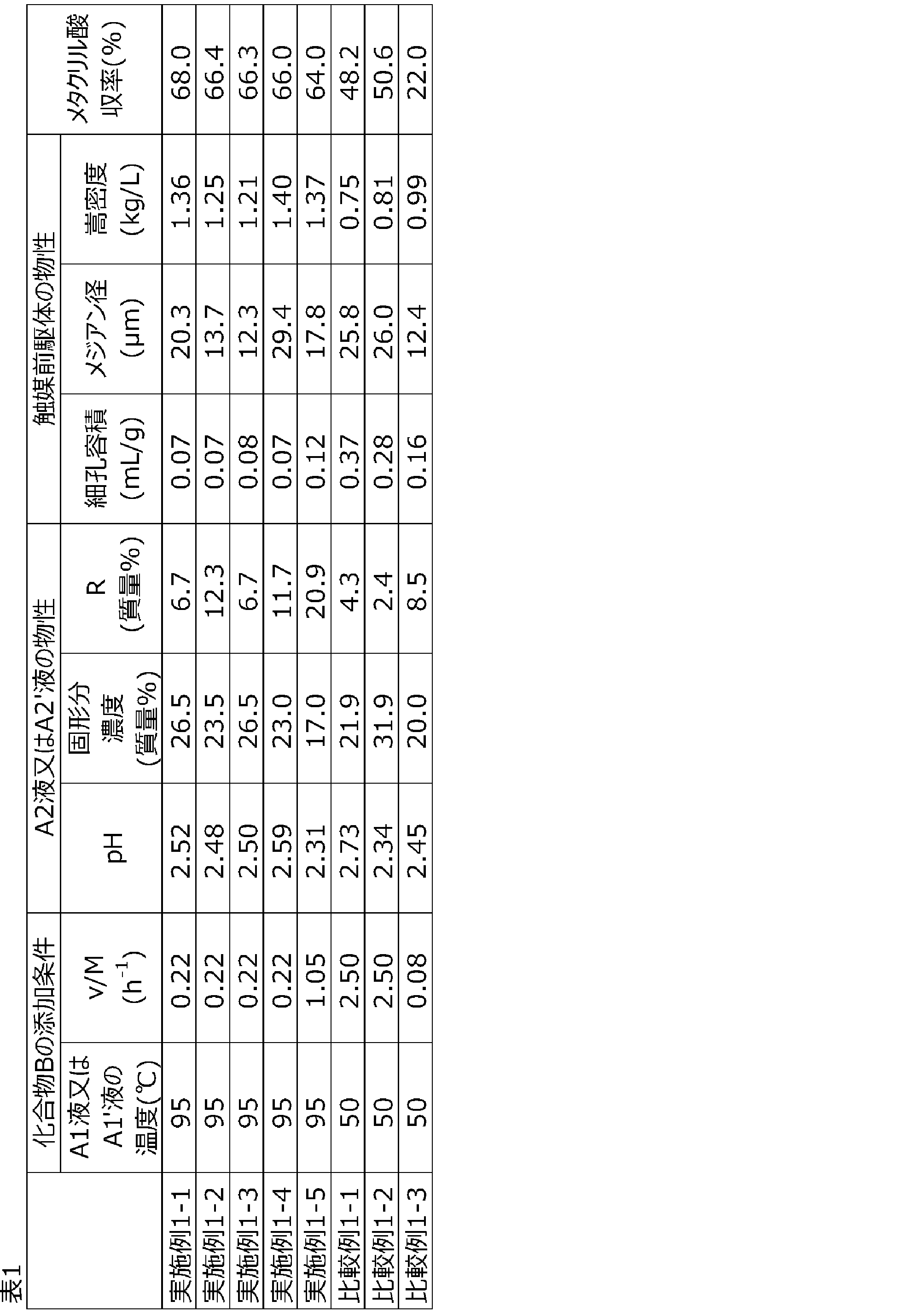
なお、本実施例1-1~1-5で得られたメタクリル酸をエステル化することでメタクリル酸エステルを得ることができる。
<実施例2-1>
25℃の純水400部を溶媒として、三酸化モリブデン100部、メタバナジン酸アンモニウム7.5部、85質量%リン酸水溶液11.4部、及び硝酸銅(II)三水和物7.0部を添加した。得られたスラリーを撹拌しながら95℃まで昇温し、液温を95℃に保ちつつ3時間撹拌した。次いで、液温を95℃に保って撹拌しながら、炭酸水素セシウム15.7部を純水20部に溶解した溶液を混合して15分撹拌し、A1液を得た。
次いで、得られた乾燥物粒子100部に対して、ヒドロキシプロピルセルロース5部、純水4部、及びエタノール16部を混合し、粘土状になるまで混練して混合物を得た。該混合物を押出成形機を用いて押出圧力10MPaで押し出して、直径5.5mm、高さ5mmの円柱状に成形した。これを空気流通下25℃で12時間乾燥し、次いで空気雰囲気下、380℃で2時間焼成して触媒成形体を得た。該触媒成形体の酸素以外の元素組成はMo12P1.7V1.1Cu0.5Cs1.4であり、アンモニウム根のモル比率は1以下であった。また、細孔分布曲線において細孔直径0.05~10μmの範囲に2本のピークを有していた。該触媒成形体の比表面積、細孔容積、及び細孔分布曲線におけるIB/IAを表2に示す。
反応温度:285℃
原料ガスと触媒成形体との接触時間:3.6秒
実施例2-1と同様の方法によりA1液を得た。
次いで、該A1液の温度を95℃に保ち、回転翼撹拌機を用いて110rpmで撹拌しながら、炭酸アンモニウム12.3部を純水20部に溶解した溶液を添加した。添加には86.6分を要した。このときのA1液の温度及びv/Mを表2に示す。添加完了後さらに、液温を95℃に保って15分撹拌し、A2液を得た。該A2液のpH、固形分濃度及びRを表2に示す。
次いで、得られた乾燥物粒子を用いて実施例2-1と同様の方法により成形、乾燥及び焼成を行い、触媒成形体を得た。該触媒成形体の酸素以外の元素組成はMo12P1.7V1.1Cu0.5Cs1.4であり、アンモニウム根のモル比率は1以下であった。また、細孔分布曲線において細孔直径0.05~10μmの範囲に2本のピークを有していた。該触媒成形体の比表面積、細孔容積、及び細孔分布曲線におけるIB/IAを表2に示す。
実施例2-1と同様の方法によりA2液を得た。
得られたA2液を実施例2-1と同様の乾燥器入口温度で噴霧乾燥し、網目のサイズが15μmのふるいを用いてふるい分けを行い、ふるい下に落ちたものを乾燥物粒子とした。
次いで、得られた乾燥物粒子を用いて実施例2-1と同様の方法により成形、乾燥及び焼成を行い、触媒成形体を得た。該触媒成形体の酸素以外の元素組成はMo12P1.7V1.1Cu0.5Cs1.4であり、アンモニウム根のモル比率は1以下であった。また、細孔分布曲線において細孔直径0.05~10μmの範囲に2本のピークを有していた。該触媒成形体の比表面積、細孔容積、及び細孔分布曲線におけるIB/IAを表2に示す。
炭酸水素セシウム15.7部の代わりに炭酸セシウム13.5部を用いた以外は、実施例2-1と同様の方法によりA1液を得た。
次いで、該A1液を用い、実施例2-1と同様の方法によりA2液を得た。該A2液のpH、固形分濃度及びRを表2に示す。
次いで、得られた乾燥物粒子を用いて実施例2-1と同様の方法により成形、乾燥及び焼成を行い、触媒成形体を得た。該触媒成形体の酸素以外の元素組成はMo12P1.7V1.1Cu0.5Cs1.4であり、アンモニウム根のモル比率は1以下であった。また、細孔分布曲線において細孔直径0.05~10μmの範囲に2本のピークを有していた。該触媒成形体の比表面積、細孔容積、及び細孔分布曲線におけるIB/IAを表2に示す。
実施例2-1と同様の方法によりA1液を得た。
次いで、炭酸アンモニウム15.0部を純水20部に溶解した溶液の添加に21.2分を要した以外は、実施例2-1と同様の方法によりA2液を得た。このときのv/M、該A2液のpH、固形分濃度及びRを表2に示す。
次いで、得られた乾燥物粒子を用いて実施例2-1と同様の方法により成形、乾燥及び焼成を行い、触媒成形体を得た。該触媒成形体の酸素以外の元素組成はMo12P1.7V1.1Cu0.5Cs1.4であり、アンモニウム根のモル比率は1以下であった。また、細孔分布曲線において細孔直径0.05~10μmの範囲に2本のピークを有していた。該触媒成形体の比表面積、細孔容積、及び細孔分布曲線におけるIB/IAを表2に示す。
25℃の純水400部を溶媒として、三酸化モリブデン100部、メタバナジン酸アンモニウム7.5部、及び硝酸銅(II)三水和物7.0部を添加した。得られたスラリーを撹拌しながら95℃まで昇温し、液温を95℃に保ちつつ3時間撹拌した。次いで、液温を50℃に降温し、液温を50℃に保って撹拌しながら、炭酸水素セシウム15.7部を純水20部に溶解した溶液を混合して15分撹拌し、A1’液を得た。
次いで、得られた乾燥物粒子を用いて実施例2-1と同様の方法により成形、乾燥及び焼成を行い、触媒成形体を得た。該触媒成形体の酸素以外の元素組成はMo12P1.7V1.1Cu0.5Cs1.4であり、アンモニウム根のモル比率は1以下であった。また、細孔分布曲線において細孔直径0.05~10μmの範囲に2本のピークを有していた。該触媒成形体の比表面積、細孔容積、及び細孔分布曲線におけるIB/IAを表2に示す。
次いで、得られた触媒成形体を反応管に充填して触媒成形体層を形成し、実施例2-1と同様の方法によりメタクロレインの酸化反応を行った。結果を表2に示す。
25℃の純水200部を溶媒とした以外は、比較例2-1と同様の方法によりA1’液を得た。
次いで、該A1’液を用いて、比較例2-1と同様の方法によりA2’液を得た。該A2’液のpH、固形分濃度及びRを表2に示す。
得られたA2’液を実施例2-1と同様の乾燥器入口温度で噴霧乾燥し、乾燥物粒子を得た。
次いで、得られた触媒成形体を反応管に充填して触媒成形体層を形成し、実施例2-1と同様の方法によりメタクロレインの酸化反応を行った。結果を表2に示す。
実施例2-1と同様の方法によりA1液を得た。
次いで、該A1液の温度を95℃に保ち、回転翼撹拌機を用いて110rpmで撹拌しながら、炭酸アンモニウム15.0部を純水20部に溶解した溶液を添加した。添加には105.7分を要した。このときのA1液の温度及びv/Mを表2に示す。添加完了後さらに、液温を95℃に保って15分撹拌後、100℃まで昇温した。次いで液温を100℃に保って40分撹拌し、A2液を得た。該A2液のpH、固形分濃度及びRを表2に示す。
次いで、得られた乾燥物粒子を用いて実施例2-1と同様の方法により成形、乾燥及び焼成を行い、触媒成形体を得た。該触媒成形体の酸素以外の元素組成はMo12P1.7V1.1Cu0.5Cs1.4であり、アンモニウム根のモル比率は1以下であった。また、細孔分布曲線において細孔直径0.05~10μmの範囲に2本のピークを有していた。該触媒成形体の比表面積、細孔容積、及び細孔分布曲線におけるIB/IAを表2に示す。
次いで、得られた触媒成形体を反応管に充填して触媒成形体層を形成し、実施例2-1と同様の方法によりメタクロレインの酸化反応を行った。結果を表2に示す。
液温を50℃に保って撹拌しながら、炭酸水素セシウム15.7部を純水20部に溶解した溶液を混合した以外は、実施例2-1と同様の方法によりA1液を得た。
次いで、炭酸アンモニウム15.0部を純水20部に溶解した溶液の添加に184.0分を要した以外は、実施例2-1と同様の方法によりA2´液を得た。このときのv/M、該A2´液のpH、固形分濃度及びRを表2に示す。
次いで、得られた乾燥物粒子を用いて実施例2-1と同様の方法により成形、乾燥及び焼成を行い、触媒成形体を得た。該触媒成形体の酸素以外の元素組成はMo12P1.7V1.1Cu0.5Cs1.4であり、アンモニウム根のモル比率は1以下であった。また、細孔分布曲線において細孔直径0.05~10μmの範囲に2本のピークを有していた。該触媒成形体の比表面積、細孔容積、及び細孔分布曲線におけるIB/IAを表2に示す。
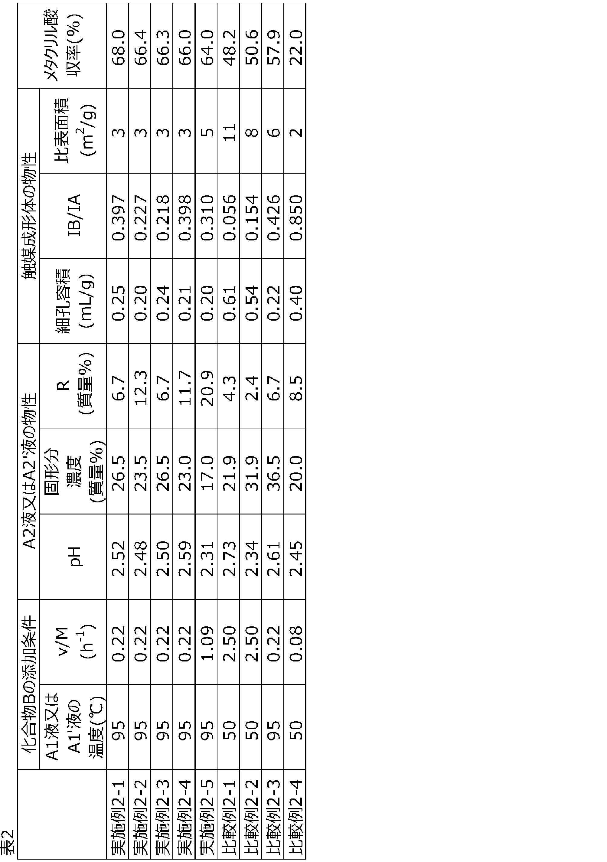
なお、本実施例2-1~2-5で得られたメタクリル酸をエステル化することでメタクリル酸エステルを得ることができる。
Claims (26)
- α,β-不飽和アルデヒドを酸化してα,β-不飽和カルボン酸を製造する際に用いられる、ケギン型ヘテロポリ酸を含む触媒の前駆体であって、
細孔容積が0.005~0.15mL/gである、触媒前駆体。 - メジアン径が1~50μmである、請求項1に記載の触媒前駆体。
- 前記メジアン径が5~40μmである、請求項2に記載の触媒前駆体。
- 前記細孔容積が0.01~0.10mL/gである、請求項1に記載の触媒前駆体。
- 嵩密度が1.15~1.6kg/Lである、請求項1に記載の触媒前駆体。
- 下記式(I)で表される組成を有する、請求項1に記載の触媒前駆体。
PaMobVcCudAeEfGg(NH4)hOi (I)
(式(I)中、P、Mo、V、Cu、NH4及びOは、それぞれ、リン、モリブデン、バナジウム、銅、アンモニウム根及び酸素を表す。Aはアンチモン、ビスマス、砒素、ゲルマニウム、テルル、セレン、ケイ素及びタングステンからなる群から選択される少なくとも1種の元素を表す。Eは鉄、亜鉛、クロム、タンタル、コバルト、ニッケル、マンガン、チタン、ニオブ及びセリウムからなる群より選択される少なくとも1種類の元素を表す。Gはリチウム、ナトリウム、カリウム、ルビジウム及びセシウムからなる群から選択される少なくとも1種の元素を表す。a~iは、各成分のモル比率を表し、b=12、a=0.5~3、c=0.01~3、d=0.01~2、e=0~3、f=0~3、g=0.01~3、h=1~30を満たし、iは前記各成分の価数を満足するのに必要な酸素のモル比率である。) - α,β-不飽和アルデヒドを酸化してα,β-不飽和カルボン酸を製造する際に用いられる、リン、モリブデン及びバナジウムを含む触媒成分を含有する触媒成形体であって、
細孔容積が0.01~0.40mL/gであり、
前記触媒成形体の細孔分布曲線において、細孔直径が0.05~10μmの範囲に頂点が存在する最も高いピーク(ピークA)の高さをIA、2番目に高いピーク(ピークB)の高さをIBとしたとき、IB/IAが0.160~0.420である、触媒成形体。 - 前記IB/IAが0.200~0.400である、請求項7に記載の触媒成形体。
- 比表面積が1~10m2/gである、請求項7に記載の触媒成形体。
- 前記比表面積が1.5~8m2/gである、請求項9に記載の触媒成形体。
- 前記細孔容積が0.10~0.35mL/gである、請求項7に記載の触媒成形体。
- 前記ピークA及び前記ピークBの頂点が、細孔直径が0.08~8μmの範囲に存在する、請求項7に記載の触媒成形体。
- 押出成形体である、請求項7に記載の触媒成形体。
- 請求項1に記載の触媒前駆体の製造方法であって、
(i)リン、モリブデン及びバナジウムを含む溶液又はスラリー(A1液)を得る工程と、
(ii)前記A1液に、アンモニウム根を含む原料化合物(化合物B)を添加して、
pHが3以下であるスラリー(A2液)を得る工程と、
(iii)前記A2液を乾燥して乾燥粒子物を得る工程と、
を含み、
前記工程(ii)において、下記式(II)を満たすように化合物Bを添加する、触媒前駆体の製造方法。
v/M=0.10~1.80 (II)
(式(II)中、MはA1液に含まれるモリブデンのモル数(mol)であり、vはアンモニウム根の添加速度(mol/h)である。) - 請求項14に記載の方法により製造された触媒前駆体から触媒成形体を得る方法であって、
(iv)前記乾燥物粒子を押出成形して触媒成形体を得る工程
を含む、触媒成形体の製造方法。 - 請求項1から6のいずれか1項に記載の触媒前駆体、又は請求項14に記載の方法により製造された触媒前駆体を焼成する、触媒の製造方法。
- 請求項7に記載の触媒成形体の製造方法であって、
(i)リン、モリブデン及びバナジウムを含む溶液又はスラリー(A1液)を得る工程と、
(ii)前記A1液に、アンモニウム根を含む原料化合物(化合物B)を添加して、
pHが3以下であるスラリー(A2液)を得る工程と、
(iii)前記A2液を乾燥して乾燥粒子物を得る工程と、
(iv)前記乾燥物粒子を押出成形して触媒成形体を得る工程と、
を含み、
前記工程(ii)において、下記式(II)を満たすように化合物Bを添加する、触媒成形体の製造方法。
v/M=0.10~1.80 (II)
(式(II)中、MはA1液に含まれるモリブデンのモル数(mol)であり、vはアンモニウム根の添加速度(mol/h)である。) - 前記A2液の固形分濃度が30質量%以下である、請求項15又は17に記載の触媒成形体の製造方法。
- 前記A2液において、モリブデン元素、リン元素及びバナジウム元素の合計質量に対する、溶解しているモリブデン元素、リン元素及びバナジウム元素の合計質量の割合をRとしたとき、Rが5~25質量%である、請求項15又は17に記載の触媒成形体の製造方法。
- 前記工程(ii)において、温度が90~99℃である前記A1液を回転数70~140rpmで撹拌しながら化合物Bを添加する、請求項15又は17に記載の触媒成形体の製造方法。
- 前記工程(iii)において、前記A2液を噴霧乾燥する、請求項15又は17に記載の触媒成形体の製造方法。
- 前記工程(iv)が下記工程(iv-1)及び(iv-2)を含む、請求項15又は17に記載の触媒成形体の製造方法。
(iv-1)前記乾燥物粒子、液体、及びバインダーを混合して混練物を得る工程。
(iv-2)前記混練物を、押出機を用いて押出成形して触媒成形体を得る工程。 - 前記工程(iv-1)において、前記乾燥物粒子100質量部に対して、前記液体を15~60質量部、前記バインダーを0.05~15質量部混合する、請求項22に記載の触媒成形体の製造方法。
- 前記(iv-2)において、0.1~30MPaの押出圧力で押出成形する、請求項22に記載の触媒成形体の製造方法。
- 請求項1から6のいずれか一項に記載の触媒前駆体を成形及び/又は焼成して得られた触媒、又は請求項7から13のいずれか一項に記載の触媒成形体を用いて、α,β-不飽和アルデヒドを酸化してα,β-不飽和カルボン酸を製造する、α,β-不飽和カルボン酸の製造方法。
- 請求項25に記載の方法により製造されたα,β-不飽和カルボン酸をエステル化する、α,β-不飽和カルボン酸エステルの製造方法。
Priority Applications (4)
| Application Number | Priority Date | Filing Date | Title |
|---|---|---|---|
| JP2024544552A JPWO2024048703A1 (ja) | 2022-08-31 | 2023-08-31 | |
| CN202380062391.7A CN119789909A (zh) | 2022-08-31 | 2023-08-31 | 催化剂前体及其制造方法、催化剂成型体及其制造方法、催化剂的制造方法、α,β-不饱和羧酸的制造方法、以及α,β-不饱和羧酸酯的制造方法 |
| KR1020257007244A KR20250044768A (ko) | 2022-08-31 | 2023-08-31 | 촉매 전구체 및 그 제조 방법, 촉매 성형체 및 그 제조 방법, 촉매의 제조 방법, α,β-불포화 카르복실산의 제조 방법, 그리고 α,β-불포화 카르복실산에스테르의 제조 방법 |
| US19/064,349 US20250229258A1 (en) | 2022-08-31 | 2025-02-26 | CATALYST PRECURSOR AND METHOD FOR MANUFACTURING SAME, CATALYST MOLDED ARTICLE AND METHOD FOR MANUFACTURING SAME, METHOD FOR MANUFACTURING CATALYST, METHOD FOR MANUFACTURING alpha,beta-UNSATURATED CARBOXYLIC ACID, AND METHOD FOR MANUFACTURING alpha,beta-UNSATURATED CARBOXYLIC ACID ESTER |
Applications Claiming Priority (4)
| Application Number | Priority Date | Filing Date | Title |
|---|---|---|---|
| JP2022-137438 | 2022-08-31 | ||
| JP2022137438 | 2022-08-31 | ||
| JP2022139188 | 2022-09-01 | ||
| JP2022-139188 | 2022-09-01 |
Related Child Applications (1)
| Application Number | Title | Priority Date | Filing Date |
|---|---|---|---|
| US19/064,349 Continuation US20250229258A1 (en) | 2022-08-31 | 2025-02-26 | CATALYST PRECURSOR AND METHOD FOR MANUFACTURING SAME, CATALYST MOLDED ARTICLE AND METHOD FOR MANUFACTURING SAME, METHOD FOR MANUFACTURING CATALYST, METHOD FOR MANUFACTURING alpha,beta-UNSATURATED CARBOXYLIC ACID, AND METHOD FOR MANUFACTURING alpha,beta-UNSATURATED CARBOXYLIC ACID ESTER |
Publications (1)
| Publication Number | Publication Date |
|---|---|
| WO2024048703A1 true WO2024048703A1 (ja) | 2024-03-07 |
Family
ID=90099800
Family Applications (1)
| Application Number | Title | Priority Date | Filing Date |
|---|---|---|---|
| PCT/JP2023/031706 Ceased WO2024048703A1 (ja) | 2022-08-31 | 2023-08-31 | 触媒前駆体及びその製造方法、触媒成形体及びその製造方法、触媒の製造方法、α,β-不飽和カルボン酸の製造方法、並びにα,β-不飽和カルボン酸エステルの製造方法 |
Country Status (5)
| Country | Link |
|---|---|
| US (1) | US20250229258A1 (ja) |
| JP (1) | JPWO2024048703A1 (ja) |
| KR (1) | KR20250044768A (ja) |
| CN (1) | CN119789909A (ja) |
| WO (1) | WO2024048703A1 (ja) |
Cited By (1)
| Publication number | Priority date | Publication date | Assignee | Title |
|---|---|---|---|---|
| WO2025198015A1 (ja) * | 2024-03-22 | 2025-09-25 | 三菱ケミカル株式会社 | 触媒、触媒の製造方法、α,β-不飽和アルデヒド及び/又はα,β-不飽和カルボン酸、並びにα,β-不飽和カルボン酸エステルの製造方法 |
Citations (5)
| Publication number | Priority date | Publication date | Assignee | Title |
|---|---|---|---|---|
| JPH081005A (ja) * | 1994-06-22 | 1996-01-09 | Sumitomo Chem Co Ltd | メタクリル酸製造用触媒の製造法 |
| JP2011140210A (ja) * | 2009-06-24 | 2011-07-21 | Sumitomo Chemical Co Ltd | 成形体およびその製造方法、並びに触媒およびその製造方法 |
| JP2014507500A (ja) * | 2010-12-22 | 2014-03-27 | イエフペ エネルジ ヌヴェル | メソ構造化酸化物担体中に捕捉されたヘテロポリアニオンをベースとする触媒を用いる炭化水素留分の水素化分解方法 |
| JP2017176932A (ja) * | 2016-03-28 | 2017-10-05 | 三菱ケミカル株式会社 | 触媒 |
| JP2020157294A (ja) * | 2019-03-25 | 2020-10-01 | 日本化薬株式会社 | 触媒前駆体、それを用いた触媒、及びその製造方法 |
Family Cites Families (4)
| Publication number | Priority date | Publication date | Assignee | Title |
|---|---|---|---|---|
| JPH0679666B2 (ja) | 1987-06-18 | 1994-10-12 | 株式会社日本触媒 | メタクリル酸合成用触媒および再現性に優れたその製造方法 |
| JP2000084412A (ja) | 1998-09-17 | 2000-03-28 | Mitsubishi Rayon Co Ltd | メタクリル酸製造用触媒、その製造方法、およびメタクリル酸の製造方法 |
| JP5473744B2 (ja) | 2010-04-21 | 2014-04-16 | 三菱レイヨン株式会社 | メタクリル酸製造用触媒の製造方法 |
| WO2012141076A1 (ja) | 2011-04-11 | 2012-10-18 | 三菱レイヨン株式会社 | メタクリル酸製造用触媒の製造方法 |
-
2023
- 2023-08-31 JP JP2024544552A patent/JPWO2024048703A1/ja active Pending
- 2023-08-31 CN CN202380062391.7A patent/CN119789909A/zh active Pending
- 2023-08-31 KR KR1020257007244A patent/KR20250044768A/ko active Pending
- 2023-08-31 WO PCT/JP2023/031706 patent/WO2024048703A1/ja not_active Ceased
-
2025
- 2025-02-26 US US19/064,349 patent/US20250229258A1/en active Pending
Patent Citations (5)
| Publication number | Priority date | Publication date | Assignee | Title |
|---|---|---|---|---|
| JPH081005A (ja) * | 1994-06-22 | 1996-01-09 | Sumitomo Chem Co Ltd | メタクリル酸製造用触媒の製造法 |
| JP2011140210A (ja) * | 2009-06-24 | 2011-07-21 | Sumitomo Chemical Co Ltd | 成形体およびその製造方法、並びに触媒およびその製造方法 |
| JP2014507500A (ja) * | 2010-12-22 | 2014-03-27 | イエフペ エネルジ ヌヴェル | メソ構造化酸化物担体中に捕捉されたヘテロポリアニオンをベースとする触媒を用いる炭化水素留分の水素化分解方法 |
| JP2017176932A (ja) * | 2016-03-28 | 2017-10-05 | 三菱ケミカル株式会社 | 触媒 |
| JP2020157294A (ja) * | 2019-03-25 | 2020-10-01 | 日本化薬株式会社 | 触媒前駆体、それを用いた触媒、及びその製造方法 |
Cited By (1)
| Publication number | Priority date | Publication date | Assignee | Title |
|---|---|---|---|---|
| WO2025198015A1 (ja) * | 2024-03-22 | 2025-09-25 | 三菱ケミカル株式会社 | 触媒、触媒の製造方法、α,β-不飽和アルデヒド及び/又はα,β-不飽和カルボン酸、並びにα,β-不飽和カルボン酸エステルの製造方法 |
Also Published As
| Publication number | Publication date |
|---|---|
| KR20250044768A (ko) | 2025-04-01 |
| US20250229258A1 (en) | 2025-07-17 |
| CN119789909A (zh) | 2025-04-08 |
| JPWO2024048703A1 (ja) | 2024-03-07 |
Similar Documents
| Publication | Publication Date | Title |
|---|---|---|
| JPH08299797A (ja) | 触媒及びその製造方法 | |
| JP7105395B1 (ja) | 触媒前駆体、それを用いた触媒、化合物の製造方法及び触媒の製造方法 | |
| UA82110C2 (uk) | Спосіб одержання каталізаторів на підкладці | |
| WO2014181839A1 (ja) | 不飽和アルデヒドおよび/または不飽和カルボン酸製造用触媒、その製造方法及び不飽和アルデヒドおよび/または不飽和カルボン酸の製造方法 | |
| JP5888233B2 (ja) | メタクリル酸製造用触媒の製造方法 | |
| JP5581693B2 (ja) | メタクリル酸製造用触媒およびその製造方法、並びにメタクリル酸の製造方法 | |
| US20250229258A1 (en) | CATALYST PRECURSOR AND METHOD FOR MANUFACTURING SAME, CATALYST MOLDED ARTICLE AND METHOD FOR MANUFACTURING SAME, METHOD FOR MANUFACTURING CATALYST, METHOD FOR MANUFACTURING alpha,beta-UNSATURATED CARBOXYLIC ACID, AND METHOD FOR MANUFACTURING alpha,beta-UNSATURATED CARBOXYLIC ACID ESTER | |
| JP3800043B2 (ja) | メタクリル酸製造用触媒、その製造方法およびメタクリル酸の製造方法 | |
| WO2012060281A1 (ja) | 触媒及びアクリル酸の製造方法 | |
| JP5473744B2 (ja) | メタクリル酸製造用触媒の製造方法 | |
| JP4022047B2 (ja) | メタクリル酸合成用触媒の製造方法、メタクリル酸合成用触媒およびメタクリル酸の製造方法 | |
| JP7480671B2 (ja) | 不飽和アルデヒド及び不飽和カルボン酸合成用触媒の製造方法 | |
| JP4253176B2 (ja) | アクリル酸製造用触媒およびアクリル酸の製造方法 | |
| JP7188707B2 (ja) | メタクリル酸製造用触媒およびその製造方法、並びにメタクリル酸およびメタクリル酸エステルの製造方法 | |
| JP5828260B2 (ja) | 触媒の製造方法 | |
| JP7480672B2 (ja) | 不飽和アルデヒド及び不飽和カルボン酸合成用触媒の製造方法 | |
| JP5090796B2 (ja) | メタクリル酸製造用触媒及びその製造方法並びにメタクリル酸の製造方法 | |
| JP7383202B2 (ja) | 触媒、及びそれを用いた化合物の製造方法 | |
| JP7468292B2 (ja) | 不飽和アルデヒド及び不飽和カルボン酸合成用触媒の製造方法 | |
| JP7468291B2 (ja) | 不飽和アルデヒド及び不飽和カルボン酸合成用触媒の製造方法 | |
| JP7468290B2 (ja) | 不飽和アルデヒド及び不飽和カルボン酸合成用触媒の製造方法 | |
| JP4881229B2 (ja) | メタクリル酸製造用触媒、その製造方法及びこれを用いたメタクリル酸の製造方法 | |
| CN118265571A (zh) | 催化剂和使用该催化剂的化合物的制造方法 | |
| WO2025198015A1 (ja) | 触媒、触媒の製造方法、α,β-不飽和アルデヒド及び/又はα,β-不飽和カルボン酸、並びにα,β-不飽和カルボン酸エステルの製造方法 | |
| WO2017221615A1 (ja) | メタクリル酸製造用触媒の製造方法、メタクリル酸の製造方法、およびメタクリル酸エステルの製造方法 |
Legal Events
| Date | Code | Title | Description |
|---|---|---|---|
| 121 | Ep: the epo has been informed by wipo that ep was designated in this application |
Ref document number: 23860465 Country of ref document: EP Kind code of ref document: A1 |
|
| WWE | Wipo information: entry into national phase |
Ref document number: 2024544552 Country of ref document: JP |
|
| WWE | Wipo information: entry into national phase |
Ref document number: 202380062391.7 Country of ref document: CN |
|
| ENP | Entry into the national phase |
Ref document number: 20257007244 Country of ref document: KR Kind code of ref document: A |
|
| WWE | Wipo information: entry into national phase |
Ref document number: 1020257007244 Country of ref document: KR |
|
| WWE | Wipo information: entry into national phase |
Ref document number: 202547027677 Country of ref document: IN |
|
| NENP | Non-entry into the national phase |
Ref country code: DE |
|
| WWP | Wipo information: published in national office |
Ref document number: 1020257007244 Country of ref document: KR |
|
| WWP | Wipo information: published in national office |
Ref document number: 202380062391.7 Country of ref document: CN |
|
| WWP | Wipo information: published in national office |
Ref document number: 202547027677 Country of ref document: IN |
|
| 122 | Ep: pct application non-entry in european phase |
Ref document number: 23860465 Country of ref document: EP Kind code of ref document: A1 |