WO2024047930A1 - 同期機制御装置、圧縮システム、冷凍サイクル装置 - Google Patents
同期機制御装置、圧縮システム、冷凍サイクル装置 Download PDFInfo
- Publication number
- WO2024047930A1 WO2024047930A1 PCT/JP2023/015441 JP2023015441W WO2024047930A1 WO 2024047930 A1 WO2024047930 A1 WO 2024047930A1 JP 2023015441 W JP2023015441 W JP 2023015441W WO 2024047930 A1 WO2024047930 A1 WO 2024047930A1
- Authority
- WO
- WIPO (PCT)
- Prior art keywords
- synchronous machine
- magnetic flux
- command
- axis
- current
- Prior art date
- Legal status (The legal status is an assumption and is not a legal conclusion. Google has not performed a legal analysis and makes no representation as to the accuracy of the status listed.)
- Ceased
Links
Images












Classifications
-
- H—ELECTRICITY
- H02—GENERATION; CONVERSION OR DISTRIBUTION OF ELECTRIC POWER
- H02P—CONTROL OR REGULATION OF ELECTRIC MOTORS, ELECTRIC GENERATORS OR DYNAMO-ELECTRIC CONVERTERS; CONTROLLING TRANSFORMERS, REACTORS OR CHOKE COILS
- H02P21/00—Arrangements or methods for the control of electric machines by vector control, e.g. by control of field orientation
- H02P21/14—Estimation or adaptation of machine parameters, e.g. flux, current or voltage
- H02P21/141—Flux estimation
-
- H—ELECTRICITY
- H02—GENERATION; CONVERSION OR DISTRIBUTION OF ELECTRIC POWER
- H02P—CONTROL OR REGULATION OF ELECTRIC MOTORS, ELECTRIC GENERATORS OR DYNAMO-ELECTRIC CONVERTERS; CONTROLLING TRANSFORMERS, REACTORS OR CHOKE COILS
- H02P21/00—Arrangements or methods for the control of electric machines by vector control, e.g. by control of field orientation
- H02P21/14—Estimation or adaptation of machine parameters, e.g. flux, current or voltage
- H02P21/18—Estimation of position or speed
-
- H—ELECTRICITY
- H02—GENERATION; CONVERSION OR DISTRIBUTION OF ELECTRIC POWER
- H02P—CONTROL OR REGULATION OF ELECTRIC MOTORS, ELECTRIC GENERATORS OR DYNAMO-ELECTRIC CONVERTERS; CONTROLLING TRANSFORMERS, REACTORS OR CHOKE COILS
- H02P21/00—Arrangements or methods for the control of electric machines by vector control, e.g. by control of field orientation
- H02P21/22—Current control, e.g. using a current control loop
-
- H—ELECTRICITY
- H02—GENERATION; CONVERSION OR DISTRIBUTION OF ELECTRIC POWER
- H02P—CONTROL OR REGULATION OF ELECTRIC MOTORS, ELECTRIC GENERATORS OR DYNAMO-ELECTRIC CONVERTERS; CONTROLLING TRANSFORMERS, REACTORS OR CHOKE COILS
- H02P29/00—Arrangements for regulating or controlling electric motors, appropriate for both AC and DC motors
- H02P29/02—Providing protection against overload without automatic interruption of supply
- H02P29/032—Preventing damage to the motor, e.g. setting individual current limits for different drive conditions
-
- H—ELECTRICITY
- H02—GENERATION; CONVERSION OR DISTRIBUTION OF ELECTRIC POWER
- H02P—CONTROL OR REGULATION OF ELECTRIC MOTORS, ELECTRIC GENERATORS OR DYNAMO-ELECTRIC CONVERTERS; CONTROLLING TRANSFORMERS, REACTORS OR CHOKE COILS
- H02P29/00—Arrangements for regulating or controlling electric motors, appropriate for both AC and DC motors
- H02P29/60—Controlling or determining the temperature of the motor or of the drive
- H02P29/66—Controlling or determining the temperature of the rotor
- H02P29/662—Controlling or determining the temperature of the rotor the rotor having permanent magnets
-
- F—MECHANICAL ENGINEERING; LIGHTING; HEATING; WEAPONS; BLASTING
- F25—REFRIGERATION OR COOLING; COMBINED HEATING AND REFRIGERATION SYSTEMS; HEAT PUMP SYSTEMS; MANUFACTURE OR STORAGE OF ICE; LIQUEFACTION SOLIDIFICATION OF GASES
- F25B—REFRIGERATION MACHINES, PLANTS OR SYSTEMS; COMBINED HEATING AND REFRIGERATION SYSTEMS; HEAT PUMP SYSTEMS
- F25B13/00—Compression machines, plants or systems, with reversible cycle
-
- F—MECHANICAL ENGINEERING; LIGHTING; HEATING; WEAPONS; BLASTING
- F25—REFRIGERATION OR COOLING; COMBINED HEATING AND REFRIGERATION SYSTEMS; HEAT PUMP SYSTEMS; MANUFACTURE OR STORAGE OF ICE; LIQUEFACTION SOLIDIFICATION OF GASES
- F25B—REFRIGERATION MACHINES, PLANTS OR SYSTEMS; COMBINED HEATING AND REFRIGERATION SYSTEMS; HEAT PUMP SYSTEMS
- F25B2600/00—Control issues
- F25B2600/02—Compressor control
- F25B2600/021—Inverters therefor
-
- F—MECHANICAL ENGINEERING; LIGHTING; HEATING; WEAPONS; BLASTING
- F25—REFRIGERATION OR COOLING; COMBINED HEATING AND REFRIGERATION SYSTEMS; HEAT PUMP SYSTEMS; MANUFACTURE OR STORAGE OF ICE; LIQUEFACTION SOLIDIFICATION OF GASES
- F25B—REFRIGERATION MACHINES, PLANTS OR SYSTEMS; COMBINED HEATING AND REFRIGERATION SYSTEMS; HEAT PUMP SYSTEMS
- F25B2600/00—Control issues
- F25B2600/25—Control of valves
- F25B2600/2513—Expansion valves
-
- H—ELECTRICITY
- H02—GENERATION; CONVERSION OR DISTRIBUTION OF ELECTRIC POWER
- H02P—CONTROL OR REGULATION OF ELECTRIC MOTORS, ELECTRIC GENERATORS OR DYNAMO-ELECTRIC CONVERTERS; CONTROLLING TRANSFORMERS, REACTORS OR CHOKE COILS
- H02P2207/00—Indexing scheme relating to controlling arrangements characterised by the type of motor
- H02P2207/05—Synchronous machines, e.g. with permanent magnets or DC excitation
-
- H—ELECTRICITY
- H02—GENERATION; CONVERSION OR DISTRIBUTION OF ELECTRIC POWER
- H02P—CONTROL OR REGULATION OF ELECTRIC MOTORS, ELECTRIC GENERATORS OR DYNAMO-ELECTRIC CONVERTERS; CONTROLLING TRANSFORMERS, REACTORS OR CHOKE COILS
- H02P25/00—Arrangements or methods for the control of AC motors characterised by the kind of AC motor or by structural details
- H02P25/02—Arrangements or methods for the control of AC motors characterised by the kind of AC motor or by structural details characterised by the kind of motor
- H02P25/022—Synchronous motors
- H02P25/024—Synchronous motors controlled by supply frequency
Definitions
- the present disclosure relates to a synchronous machine control device, a compression system, and a refrigeration cycle device.
- Patent Document 1 discloses a drive control device for an electric motor.
- the drive control device disclosed in Patent Document 1 includes a PWM current control means for supplying a sinusoidal current of a predetermined amplitude and a predetermined phase according to a torque command value to an AC motor, and a PWM current control means that supplies a sinusoidal current of a predetermined amplitude and a predetermined phase according to a torque command value, A voltage phase control means for supplying an alternating current having a phase to an AC motor, a control switching means for switching between PWM current control by the PWM current control means and voltage phase control by the voltage phase control means, and a temperature of a permanent magnet of the AC motor.
- the torque command during PWM current control is calculated by calculating the torque during PWM current control and adding the torque difference obtained by subtracting the torque during PWM current control from the calculated torque during voltage phase control to the torque command value during PWM current control.
- a correction means for correcting the value.
- Patent Document 1 estimates the magnet temperature using the magnetic flux of a permanent magnet (magnet magnetic flux). Patent Document 1 estimates magnet magnetic flux using a dq-axis voltage equation and a motor torque equation. In this case, the equation used to estimate the magnet magnetic flux includes the command voltage (dq-axis voltage command value) and the winding resistance (see equations 14 to 20 of Patent Document 1). Therefore, it is susceptible to voltage errors due to inverter dead time, resistance, etc., and the accuracy of estimating the magnetic flux of the magnet decreases.
- the present disclosure provides a synchronous machine control device, a compression system, and a refrigeration cycle device that make it possible to improve the accuracy of estimating the magnetic flux of a permanent magnet of a synchronous machine.
- a synchronous machine control device includes a drive circuit that drives a synchronous machine, a detection circuit that detects a current flowing through the synchronous machine and outputs a detected current indicating the current, and a control circuit that controls the drive circuit. and.
- the control circuit specifies the command voltage to be applied to the synchronous machine, performs synchronous machine control processing to control the drive circuit so that the drive circuit applies the command voltage to the synchronous machine, and estimates the magnetic flux of the permanent magnet of the synchronous machine. It has a function to perform magnet magnetic flux estimation processing.
- the synchronous machine control process specifies a command voltage so that the reactive power component of the synchronous machine satisfies a predetermined condition.
- the magnet flux estimation process is based on the relationship satisfied by the armature linkage flux of the synchronous machine, the armature reaction flux of the synchronous machine, and the magnet magnetic flux of the permanent magnet of the synchronous machine when the reactive power component of the synchronous machine satisfies a predetermined condition. , the magnet magnetic flux is estimated from the armature linkage flux obtained from the detected current and the command voltage, and the armature reaction magnetic flux obtained from the inductance of the synchronous machine and the detected current.
- a compression system includes a compressor and a control device that controls the compressor.
- the compressor includes a closed container that forms a flow path for a working medium containing ethylene-based fluoroolefin as a refrigerant component, a compression mechanism located within the closed container that compresses the working medium, and a compression mechanism located within the closed container.
- a synchronous machine that operates the synchronous machine.
- the control device includes a drive circuit that drives the synchronous machine, a detection circuit that detects a current flowing through the synchronous machine and outputs a detected current indicating the current, and a control circuit that controls the drive circuit.
- the control circuit specifies the command voltage to be applied to the synchronous machine, performs synchronous machine control processing to control the drive circuit so that the drive circuit applies the command voltage to the synchronous machine, and estimates the magnetic flux of the permanent magnet of the synchronous machine. It has a function of executing magnet magnetic flux estimation processing and stop processing of stopping the synchronous machine when it is determined that the ambient temperature of the synchronous machine exceeds a predetermined temperature based on the magnet magnetic flux.
- the synchronous machine control process specifies a command voltage so that the reactive power component of the synchronous machine satisfies a predetermined condition.
- the magnet flux estimation process is based on the relationship satisfied by the armature linkage flux of the synchronous machine, the armature reaction flux of the synchronous machine, and the magnet magnetic flux of the permanent magnet of the synchronous machine when the reactive power component of the synchronous machine satisfies a predetermined condition. , the magnet magnetic flux is estimated from the armature linkage flux obtained from the detected current and the command voltage, and the armature reaction magnetic flux obtained from the inductance of the synchronous machine and the detected current.
- a refrigeration cycle device includes a refrigeration cycle circuit that includes a compressor, a condenser, an expansion valve, and an evaporator, and in which a working medium circulates, and a control device that controls the refrigeration cycle circuit.
- the working medium includes an ethylene-based fluoroolefin as a refrigerant component
- the compressor includes a closed container that constitutes a flow path for the working medium, a compression mechanism that is located in the closed container and compresses the working medium, and a compressor that is located in the closed container and that compresses the working medium. and a synchronous machine located at the compressor to operate the compression mechanism.
- the control device includes a drive circuit that drives the synchronous machine, a detection circuit that detects a current flowing through the synchronous machine and outputs a detected current indicating the current, and a control circuit that controls the drive circuit.
- the control circuit specifies the command voltage to be applied to the synchronous machine, performs synchronous machine control processing to control the drive circuit so that the drive circuit applies the command voltage to the synchronous machine, and estimates the magnetic flux of the permanent magnet of the synchronous machine. It has a function of executing magnet magnetic flux estimation processing and stop processing of stopping the synchronous machine when it is determined that the ambient temperature of the synchronous machine exceeds a predetermined temperature based on the magnet magnetic flux.
- the synchronous machine control process specifies a command voltage so that the reactive power component of the synchronous machine satisfies a predetermined condition.
- the magnet flux estimation process is based on the relationship satisfied by the armature linkage flux of the synchronous machine, the armature reaction flux of the synchronous machine, and the magnet magnetic flux of the permanent magnet of the synchronous machine when the reactive power component of the synchronous machine satisfies a predetermined condition.
- the magnet magnetic flux is estimated from the armature linkage flux obtained from the detected current and the command voltage, and the armature reaction magnetic flux obtained from the inductance of the synchronous machine and the detected current.
- aspects of the present disclosure enable improved accuracy in estimating the magnetic flux of the permanent magnets of a synchronous machine.
- Circuit diagram of a configuration example of the drive circuit of the synchronous machine drive system in Figure 1 Block diagram of the voltage generation section of the synchronous machine control device of the synchronous machine drive system in Figure 1
- An explanatory diagram of the coordinate system used in the synchronous machine control device in Figure 3 An explanatory diagram of the current and magnetic flux vector of the synchronous machine by the synchronous machine control device in Figure 3
- An explanatory diagram of the current and magnetic flux vector of the synchronous machine by the synchronous machine control device in Figure 3 An explanatory diagram of the current and magnetic flux vector of the synchronous machine by the synchronous machine control device in Figure 3
- a graph of an example of a comparison between the estimated value and the true value of the magnet magnetic flux by the synchronous machine control device in Figure 1 A graph of another example of comparison between the estimated
- Block diagram of the voltage generation section of the synchronous machine control device according to the fourth embodiment Block diagram of a configuration example of the command phase identification section of the voltage generation section in FIG. 15
- Block diagram of the voltage generation section of the synchronous machine control device according to the fifth embodiment Block diagram of a configuration example of the command phase identification section of the voltage generation section in FIG. 17
- Block diagram of a voltage generation unit of a synchronous machine control device according to a sixth embodiment Block diagram of the first configuration example of the command phase identification section of the voltage generation section in FIG. 19
- Block diagram of the second configuration example of the command phase identification unit of the voltage generation unit in FIG. 19 Block diagram of the third configuration example of the command phase identification section of the voltage generation section in FIG.
- Block diagram of the voltage generation section of the synchronous machine control device according to Embodiment 7 An explanatory diagram of the coordinate system used in the synchronous machine control device in Fig. 23
- Block diagram of a voltage generation section of a synchronous machine control device according to an eighth embodiment An explanatory diagram of the current and magnetic flux vector of the synchronous machine by the synchronous machine control device in Fig. 25
- FIG. 25 A graph of an example of a comparison between the estimated value and the true value of the magnet magnetic flux by the synchronous machine control device in Figure 25 A graph of another example of the comparison between the estimated value and true value of the magnet magnetic flux by the synchronous machine control device in Figure 25
- Block diagram of a voltage generation section of a synchronous machine control device according to a ninth embodiment Block diagram of the voltage generation section of the synchronous machine control device according to Embodiment 10
- Block diagram of the voltage generation section of the synchronous machine control device according to Embodiment 12 Block diagram of a voltage generation section of a synchronous machine control device according to a thirteenth embodiment Block diagram of the voltage generation section of the synchronous machine control device according to the fourteenth embodiment
- prefixes such as “first” and “second” may be omitted in consideration of the readability of the text.
- symbols indicating physical quantities such as magnetic flux, voltage, and current may indicate a vector if they are in bold, and may indicate a scalar if they are not in bold (if they are standard).
- FIG. 1 is a block diagram of a configuration example of a synchronous machine drive system 4 including a synchronous machine control device 1 according to the first embodiment.
- the synchronous machine drive system 4 in FIG. 1 controls the operation of a synchronous machine (synchronous motor) 10 in accordance with a control command.
- the synchronous machine 10 is, for example, a brushless motor (three-phase brushless motor).
- the synchronous machine 10 includes, for example, a rotor and a stator provided around the rotor.
- the synchronous machine drive system 4 in FIG. 1 includes a synchronous machine control device 1, a drive circuit 2, and a detection circuit 3.
- FIG. 2 shows a circuit diagram of a configuration example of the drive circuit 2.
- the drive circuit 2 in FIG. 2 is connected between the synchronous machine 10 and the power supply 11.
- the drive circuit 2 in FIG. 2 supplies drive power to the synchronous machine 10 based on power from the power supply 11.
- power supply 11 is an AC power supply.
- the drive circuit 2 supplies drive power to the synchronous machine 10 based on AC power from the power source 11.
- the drive circuit 2 supplies three-phase AC power to the synchronous machine 10 as drive power.
- Drive circuit 2 includes a converter circuit 21 and an inverter circuit 22.
- the converter circuit 21 converts AC power from the power supply 11 into DC power.
- Converter circuit 21 includes a rectifier circuit 21a and a smoothing circuit 21b.
- the rectifier circuit 21a is a diode bridge composed of a plurality of diodes D1 to D4.
- a power supply 11 is connected between the input terminals of the rectifier circuit 21a (the connection point between the diodes D1 and D2, and the connection point between the diodes D3 and D4), and the output terminal of the rectification circuit 21a (the connection point between the diodes D1 and D3, and the connection point between the diodes D1 and D3).
- a smoothing circuit 21b is connected between the connection point of diodes D2 and D4.
- the smoothing circuit 21b includes a series circuit of an inductor L1 and a capacitor C1, smoothes the voltage between the output terminals of the rectifier circuit 21a, and outputs it as a voltage across the capacitor C1. Since the configurations of the rectifying circuit 21a and the smoothing circuit 21b in FIG. 2 are well known, detailed explanation thereof will be omitted.
- the inverter circuit 22 supplies three-phase AC power to the synchronous machine 10 based on the DC power from the converter circuit 21 .
- the inverter circuit 22 includes a plurality of arms U1, U2, V1, V2, W1, and W2. Each of the plurality of arms U1, U2, V1, V2, W1, and W2 is composed of a semiconductor switching element such as a transistor.
- the series circuit of arms U1 and U2 is connected in parallel to capacitor C1 of converter circuit 21, and constitutes a U-phase leg.
- the series circuit of arms V1 and V2 is connected in parallel to capacitor C1 of converter circuit 21, and constitutes a V-phase leg.
- the series circuit of arms W1 and W2 is connected in parallel to capacitor C1 of converter circuit 21, and constitutes a W-phase leg.
- the inverter circuit 22 can output a U-phase output voltage v u , a V-phase output voltage v v , and a W-phase output voltage v w to the synchronous machine 10 . Since the configuration of the inverter circuit 22 in FIG. 2 is well known, detailed explanation thereof will be omitted.
- the detection circuit 3 in FIG. 1 detects the current flowing through the synchronous machine 10 and outputs a detected current indicating this current (that is, a detected value of the current flowing through the synchronous machine 10). In this embodiment, the detection circuit 3 detects the output alternating current of the U-phase and W-phase legs of the drive circuit 2.
- the detection circuit 3 in FIG. 1 includes a first alternating current sensor 31 and a second alternating current sensor 32.
- the first AC current sensor 31 detects the output AC current (current value) of the U-phase leg of the drive circuit 2, and a first detection current (first detection current value) indicating the detected output AC current (current value).
- i u is output to the synchronous machine control device 1.
- the second AC current sensor 32 detects the output AC current (current value) of the W-phase leg of the drive circuit 2, and a second detection current (second detection current value) indicating the detected output AC current (current value).
- i w is output to the synchronous machine control device 1.
- the synchronous machine control device 1 in FIG. 1 is connected to a drive circuit 2 and a detection circuit 3.
- the synchronous machine control device 1 in FIG. 1 can be realized, for example, by a computer system including at least one or more processors (microprocessors) and one or more memories. Further, the synchronous machine control device 1 in FIG. 1 may be configured by a logic circuit.
- the synchronous machine control device 1 in FIG. 1 drives the synchronous machine 10 in accordance with a given control command.
- the synchronous machine control device 1 is configured to perform speed/position sensorless operation of the synchronous machine 10.
- Speed/position sensorless operation is operation that does not use position sensors such as encoders and resolvers.
- the synchronous machine control device 1 in FIG. 1 includes a voltage generation section 5 and a duty generation section 6.
- the voltage generation unit 5 and duty generation unit 6 in FIG. 1 are visual representations of processing (signal processing, transfer functions, etc.) executed by the synchronous machine control device 1, rather than actual configurations.
- the voltage generation unit 5 generates a U-phase output that is output from the drive circuit 2 to the synchronous machine 10 based on the control command and the detection current (first detection current i u and second detection current i w ) from the detection circuit 3.
- Command voltages v u * , v v * , v w * corresponding to the voltage v u , the V-phase output voltage v v , and the W -phase output voltage v w , respectively are specified.
- the voltage generation unit 5 updates the command voltages v u * , v v * , v w * at a predetermined control cycle. The detailed contents of the voltage generation section 5 will be described later.
- the duty generation unit 6 executes PWM control of a plurality of semiconductor switching element groups of the inverter circuit 22 of the drive circuit 2 so that the drive circuit 2 operates the synchronous machine 10. More specifically, the duty generation unit 6 controls a plurality of semiconductor switching elements of the inverter circuit 22 so that the inverter circuit 22 supplies three-phase AC power to the synchronous machine 10 based on the DC power from the smoothing circuit 21b. Controls switching of U1, U2, V1, V2, W1, and W2.
- the duty generation unit 6 generates a U-phase output voltage v u , a V-phase output voltage v v and W that correspond to the command voltages v u * , v v * , v w * from the voltage generation unit 5 , respectively.
- the duty ratios D u , D v , and D w of the U-phase, V-phase, and W-phase legs of the drive circuit 2 are specified so that the phase output voltage v w is output from the drive circuit 2 to the synchronous machine 10 .
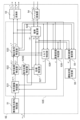
- FIG. 3 shows a block diagram of a configuration example of the voltage generation section 5 of the synchronous machine control device 1.
- the voltage generating section 5 in FIG. 3 includes a reactive power command specifying section 51, a synchronous machine control section 52, an ⁇ , / ⁇ , ⁇ conversion unit (three-phase two-phase coordinate conversion unit) 54, a magnet magnetic flux estimation unit 55, and an operating state determination unit 56.
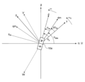
- FIG. 4 is an explanatory diagram of a coordinate system used in the synchronous machine control device 1.
- angle means electrical angle.
- the UVW coordinate system in FIG. 4 is a fixed coordinate system based on the stator of the synchronous machine 10, and is defined by a U axis, a V axis, and a W axis at 120 degree intervals.
- the U-axis, V-axis, and W-axis correspond to the U-phase, V-phase, and W-phase windings of the stator of the synchronous machine 10, respectively.
- the U-axis, V-axis, and W-axis do not rotate even if the rotor of the synchronous machine 10 rotates. That is, the U axis, V axis, and W axis are fixed axes.
- the ⁇ coordinate system in FIG. 4 is a two-dimensional orthogonal coordinate system, and is defined by an ⁇ axis and a ⁇ axis that are orthogonal to each other.
- the ⁇ axis is set to coincide with the U axis.
- the ⁇ axis is an axis obtained by rotating the ⁇ axis by 90 degrees in the advancing direction.
- the ⁇ coordinate system like the UVW coordinate system, is a fixed coordinate system based on the stator of the synchronous machine 10.
- the dq coordinate system in FIG. 4 is a rotating coordinate system based on the rotor (permanent magnet 10a) of the synchronous machine 10.
- the dq coordinate system is a two-dimensional orthogonal coordinate system and is defined by a d-axis and a q-axis that are orthogonal to each other.
- the d-axis and the q-axis rotate at the same speed as the rotation speed (rotation speed) of the magnetic flux produced by the permanent magnet 10a with respect to the ⁇ -axis and the ⁇ -axis.
- the rotational speed of the magnetic flux produced by the permanent magnet 10a is the rotational speed of the rotor of the synchronous machine 10.
- the counterclockwise direction is the direction in which the phase advances.
- the d-axis is set as an axis extending in the direction of magnetic flux produced by the permanent magnet 10a.
- the q-axis is set as an axis obtained by rotating the d-axis by 90 degrees in the advancing direction.
- the dmqm coordinate system in FIG. 4 is a coordinate system set to realize maximum torque/current (maximum torque per ampere: MTPA) control.
- the dmqm coordinate system is a two-dimensional orthogonal coordinate system and is defined by a dm axis and a qm axis that are orthogonal to each other.
- the qm-axis is set so that the direction of the current vector to be supplied to the synchronous machine 10 coincides with the direction of the qm-axis when realizing maximum torque/current control. In other words, the qm axis coincides with the current vector during maximum torque/current control.
- the dm axis is an axis delayed by 90 degrees from the qm axis in the dmqm coordinate system, and the three-phase AC power is supplied to the synchronous machine 10 so that the dm axis current, which is the dm axis component of the current of the synchronous machine 10, is 0.
- ⁇ dm indicates the angle of the dmqm coordinate system with respect to the ⁇ coordinate system
- ⁇ m indicates the angle of the dq coordinate system with respect to the dmqm coordinate system.
- ⁇ * is the target value of the reactive power component of the synchronous machine 10.
- is the amplitude of the command magnetic flux ⁇ S * of the synchronous machine 10 .
- ⁇ ⁇ * is the ⁇ -axis component of the command magnetic flux ⁇ S * in the ⁇ coordinate system, and hereinafter may be referred to as ⁇ -axis command magnetic flux.
- ⁇ ⁇ * is the ⁇ -axis component of the command magnetic flux ⁇ S * in the ⁇ coordinate system, and hereinafter may be referred to as ⁇ -axis command magnetic flux.
- ⁇ S * is the phase of the command magnetic flux ⁇ S * of the synchronous machine 10.
- v ⁇ * is the ⁇ -axis component of the command voltage in the ⁇ coordinate system, and hereinafter may be referred to as ⁇ -axis command voltage.
- v ⁇ * is the ⁇ -axis component of the command voltage in the ⁇ coordinate system, and hereinafter may be referred to as ⁇ -axis command voltage.
- i ⁇ is the ⁇ -axis component of the detection current in the ⁇ coordinate system, and may be hereinafter referred to as ⁇ -axis detection current.
- i ⁇ is the ⁇ -axis component of the detected current in the ⁇ coordinate system, and may be hereinafter referred to as the ⁇ -axis detected current.
- T e * is a command torque as a control command.
- the command torque T e * indicates the target value of the torque of the synchronous machine 10 .
- the command torque T e * can be given to the synchronous machine control device 1 from an external device.
- the reactive power command specifying unit 51 in FIG. 3 specifies the target value ⁇ * of the reactive power component of the synchronous machine 10.
- the target value ⁇ * is given to the synchronous machine control section 52.
- the reactive power component of the synchronous machine 10 is given by the inner product of the magnetic flux of the permanent magnet 10a of the synchronous machine 10 and the current flowing through the synchronous machine 10.
- the dm-axis current i dm is set to 0 in the dmqm coordinate system.
- the inner product of the magnetic flux of the permanent magnet 10a of the synchronous machine 10 and the current flowing through the synchronous machine 10 is set to 0, that is, the target value ⁇ * of the reactive power component of the synchronous machine 10 is set to 0.
- FIG. 5 is an explanatory diagram of the current/magnetic flux vector of the synchronous machine 10.
- FIG. 5 shows the armature linkage flux of the synchronous machine 10 and the armature reaction flux of the synchronous machine 10 when the reactive power component of the synchronous machine 10 is 0 (when the DM axis current i dm is 0).
- ⁇ S is the armature linkage flux (vector) of the synchronous machine 10.
- ⁇ am is the magnetic flux (vector) of the permanent magnet 10a.
- ⁇ am is the magnetic flux (vector) of the permanent magnet 10a in the dmqm coordinate system.
- L qm is a virtual inductance and means the inductance of the qm axis in the dmqm coordinate system.
- ia is a current (that is, a detected current) (vector) flowing through the synchronous machine 10.
- ia ( idm , iqm ).
- the armature reaction magnetic flux of the synchronous machine 10 is represented by L qm i a .
- i i a (0, i qm ).
- the armature reaction magnetic flux of the synchronous machine 10 and the magnet magnetic flux of the permanent magnet 10a of the synchronous machine 10 are orthogonal to each other. Therefore, when the reactive power component of the synchronous machine 10 is 0 (when the dm axis current i dm is 0), the armature linkage magnetic flux ⁇ S of the synchronous machine 10 and the armature reaction magnetic flux L qm of the synchronous machine 10
- i a and the magnet magnetic flux ⁇ am of the permanent magnet 10a of the synchronous machine 10 is expressed by the following equation (1).
- the synchronous machine control unit 52 in FIG. 3 defines signal processing corresponding to synchronous machine control processing.
- the synchronous machine control process specifies the command voltages v u * , v v * , v w * , and drives the voltages v u , v v , v w corresponding to the command voltages v u * , v v * , v w * .
- the drive circuit 2 is controlled so that the circuit 2 applies voltage to the synchronous machine 10 .
- the synchronous machine control unit 52 specifies the command voltages v u *, v v * , v w * by specifying the ⁇ -axis and ⁇ -axis command voltages V ⁇ * , V ⁇ * .
- the synchronous machine control process specifies command voltages v u * , v v * , v w * so that the reactive power component of the synchronous machine 10 satisfies predetermined conditions.
- the predetermined condition is that the reactive power component of the synchronous machine 10 matches the target value ⁇ * .
- the target value ⁇ * is set to 0. Therefore, in this embodiment, the predetermined condition is that the reactive power component becomes zero.
- the synchronous machine control section 52 in FIG. including.
- the command amplitude specifying unit 521 specifies the amplitude
- is specified such that the reactive power component of the synchronous machine 10 satisfies a predetermined condition.
- the predetermined condition is that the reactive power component becomes 0, which means that the above formula (1) is satisfied.
- the reactive power component ⁇ of the synchronous machine 10 is expressed by the following equation (2).
- the magnet magnetic flux ⁇ am is calculated by the following formula ( 3).
- ⁇ am0 the initial value (vector) of the magnet magnetic flux ⁇ am
- ⁇ am the fluctuation value (vector) of the magnet magnetic flux ⁇ am
- ⁇ am0 ( ⁇ am0 , 0)
- ⁇ am ( ⁇ am , 0).
- the magnetic flux error ⁇ e can be expressed by the following equation (4).
- ⁇ V represents a voltage error
- ⁇ R represents a resistance error.
- FIG. 6 is an explanatory diagram of the current/magnetic flux vector of the synchronous machine 10.
- FIG. 6 shows the relationship among the command magnetic flux ⁇ S0 * set without considering the magnetic flux error ⁇ e , the armature reaction magnetic flux of the synchronous machine 10, and the magnet magnetic flux of the permanent magnet 10a of the synchronous machine 10.
- FIG. 7 is an explanatory diagram of the current/magnetic flux vector of the synchronous machine 10.
- FIG. 7 shows the relationship among the command magnetic flux ⁇ S * set so that the reactive power component ⁇ becomes 0, the armature reaction magnetic flux of the synchronous machine 10, and the magnetic flux of the permanent magnet 10a of the synchronous machine 10.
- ⁇ indicates a correction amount for correcting the command magnetic flux ⁇ S0 * to the command magnetic flux ⁇ S * such that the reactive power component ⁇ becomes 0.
- the command amplitude specifying unit 521 in FIG. 3 receives the target value ⁇ * from the reactive power command specifying unit 51, receives the estimated amplitude of armature interlinkage magnetic flux
- the command amplitude specifying unit 521 uses the amplitude
- the correction amount ⁇ is determined, and the amplitude
- feedback control include proportional (P control) control, proportional integral (PI) control, proportional differential (PD) control, and proportional integral differential (PID) control.
- P control proportional
- PI proportional integral
- PD proportional differential
- PID proportional integral differential
- K P is a proportional gain
- K I is an integral gain
- s is a Laplace operator.
- the command amplitude specifying unit 521 provides the amplitude
- the command magnetic flux identifying unit 522 identifies the ⁇ -axis command magnetic flux ⁇ ⁇ * and the ⁇ -axis command magnetic flux ⁇ ⁇ * . More specifically, the command magnetic flux identification unit 522 determines the ⁇ -axis command magnetic flux ⁇ ⁇ * and the ⁇ -axis command magnetic flux ⁇ from the amplitude
- the commanded magnetic flux specifying unit 522 in FIG. 3 receives the amplitude
- the command magnetic flux identifying unit 522 identifies the ⁇ -axis command magnetic flux ⁇ ⁇ * and the ⁇ -axis command magnetic flux ⁇ ⁇ * from the amplitude
- the command magnetic flux specifying unit 522 provides the ⁇ -axis command magnetic flux ⁇ ⁇ * and the ⁇ -axis command magnetic flux ⁇ ⁇ * to the voltage command specifying unit 523 .
- the voltage command specifying unit 523 specifies the ⁇ -axis command voltage v ⁇ * and the ⁇ -axis command voltage v ⁇ * . More specifically, the voltage command specifying unit 523 determines the ⁇ -axis command magnetic flux ⁇ ⁇ * , the ⁇ -axis command magnetic flux ⁇ ⁇ * , the ⁇ -axis estimated magnetic flux ⁇ ⁇ , and the ⁇ -axis estimated magnetic flux ⁇ ⁇ for each control cycle. , the ⁇ -axis command voltage v ⁇ * and the ⁇ -axis command voltage v ⁇ * are specified from the ⁇ -axis detection current i ⁇ and the ⁇ -axis detection current i ⁇ .
- the ⁇ -axis command voltage v ⁇ * and the ⁇ -axis command voltage v ⁇ * are expressed by the following equations (9) and (10), respectively.
- Ts is the control period
- Ra is the winding resistance of the synchronous machine 10.
- the voltage command specifying unit 523 in FIG. 3 receives the ⁇ -axis command magnetic flux ⁇ ⁇ * and the ⁇ -axis command magnetic flux ⁇ ⁇ * from the command magnetic flux specifying unit 522, and receives the ⁇ -axis estimated magnetic flux ⁇ ⁇ and the ⁇ -axis estimated magnetic flux from the magnetic flux estimation unit 524.
- ⁇ ⁇ is received, and ⁇ -axis detection current i ⁇ and ⁇ -axis detection current i ⁇ are received from u, w/ ⁇ , ⁇ converter 54 .
- the voltage command specifying unit 523 specifies the ⁇ -axis command voltage v ⁇ * and the ⁇ -axis command voltage v ⁇ * .
- the voltage command specifying unit 523 provides the ⁇ -axis command voltage v ⁇ * and the ⁇ -axis command voltage v ⁇ * to the ⁇ , ⁇ /u, v, w converting unit 53 and the magnetic flux estimating unit 524.
- the magnetic flux estimation unit 524 estimates the armature interlinkage magnetic flux ⁇ S of the synchronous machine 10.
- the magnetic flux estimating unit 524 calculates the amplitude
- ⁇ -axis estimated magnetic flux ⁇ ⁇ , and ⁇ -axis estimated magnetic flux ⁇ ⁇ are calculated.
- are expressed by the following equations (11), (12), and (13), respectively.
- ⁇ ⁇ 0 is the initial value of the ⁇ -axis estimated magnetic flux.
- ⁇ ⁇ 0 is the initial value of the ⁇ -axis estimated magnetic flux.
- the magnetic flux estimation unit 524 in FIG. 3 receives the ⁇ -axis command voltage v ⁇ * and the ⁇ -axis command voltage v ⁇ * from the voltage command specifying unit 523, and receives the ⁇ -axis detected current i ⁇ from the u, w/ ⁇ , ⁇ conversion unit 54. and ⁇ -axis detection current i ⁇ .
- the magnetic flux estimation unit 524 calculates the amplitude
- the magnetic flux estimating unit 524 gives the amplitude
- the command phase identifying unit 525 identifies the phase ⁇ S * of the command magnetic flux ⁇ s * of the synchronous machine 10 .
- the command phase identification unit 525 receives command torque T e * as a control command.
- the command phase identifying unit 525 identifies the phase ⁇ s * based on the command torque T e * .
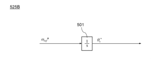
- the command phase specifying unit 525 determines the rotation angular velocity from the command torque T e * , and specifies the phase ⁇ s * by integrating the rotation angular velocity based on the control period. Note that the command phase identification unit 525 may receive the command rotational speed ⁇ ref * instead of the command torque T e * as the control command.
- the command phase identification unit 525 identifies the phase ⁇ s * based on the command rotational speed ⁇ ref * .
- the command phase identification unit 525 may identify the phase ⁇ s * by integrating the command rotation speed ⁇ ref * based on the control period.
- the command phase specifying unit 525 provides the phase ⁇ s * to the command magnetic flux specifying unit 522.
- the error variable identification unit 526 identifies the error variable ⁇ .
- the error variable ⁇ is the inner product of the magnet magnetic flux ⁇ am and the detected current i a (reactive power component of the synchronous machine 10).
- the error variable identification unit 526 determines the error variable ⁇ from the ⁇ -axis estimated magnetic flux ⁇ ⁇ , the ⁇ -axis estimated magnetic flux ⁇ ⁇ , the ⁇ -axis detected current i ⁇ , and the ⁇ -axis detected current i ⁇ . Identify.
- the ⁇ -axis magnet magnetic flux of the magnet magnetic flux ⁇ am in the ⁇ coordinate system is ⁇ am_ ⁇
- the ⁇ -axis magnet magnetic flux of the magnet magnetic flux ⁇ am in the ⁇ coordinate system is ⁇ am_ ⁇
- the ⁇ -axis magnet magnetic flux ⁇ am_ ⁇ is calculated by the following equation (14 )
- the ⁇ -axis magnet magnetic flux ⁇ am_ ⁇ is expressed by the following equation (15).
- the error variable identification unit 526 determines the magnet magnetic flux ⁇ am and the detected current i from the ⁇ -axis magnet magnetic flux ⁇ am_ ⁇ , the ⁇ -axis magnet magnetic flux ⁇ am_ ⁇ , the ⁇ -axis detection current i ⁇ , and the ⁇ -axis detection current i ⁇ .
- the inner product with a that is, the error variable ⁇ is calculated.
- the error variable ⁇ can be calculated by using the ⁇ -axis magnet magnetic flux as ⁇ am_ ⁇ , the ⁇ -axis magnet magnetic flux as ⁇ am_ ⁇ , the ⁇ -axis detection current i ⁇ , and the ⁇ -axis detection current i ⁇ . , is expressed by the following equation (16).
- the error variable identification unit 526 in FIG. 3 receives the ⁇ -axis estimated magnetic flux ⁇ ⁇ and the ⁇ -axis estimated magnetic flux ⁇ ⁇ from the magnetic flux estimation unit 524, and receives the ⁇ -axis detected current i Receive the axis detection current i ⁇ .
- the error variable identification unit 526 identifies the error variable ⁇ .
- the error variable specifying section 526 provides the error variable ⁇ to the command amplitude specifying section 521.
- the synchronous machine control process calculates the inner product (error variable ⁇ ) of the magnet magnetic flux ⁇ am and the detected current ia , and executes feedback control using the inner product (error variable ⁇ ) to control the reactive power.
- of the command magnetic flux ⁇ s * of the synchronous machine 10 is specified so that the component (error variable ⁇ ) satisfies a predetermined condition.
- the predetermined condition is that the reactive power component (error variable ⁇ ) becomes zero.
- the synchronous machine control process specifies the phase ⁇ S * of the command magnetic flux ⁇ s * based on the command torque T e * of the synchronous machine 10 . In the synchronous machine control process , the command voltage v * , v v * , v w * are specified.
- the ⁇ , ⁇ /u, v, w conversion unit 53 in FIG. 3 converts the ⁇ -axis command voltage v ⁇ * and the ⁇ -axis command voltage v ⁇ * into command voltages v u * , v v * , v w in the UVW coordinate system. Convert to * .
- the command voltages v u * , v v * , v w * are expressed by the following equation (17).
- the ⁇ , ⁇ /u, v, w converter 53 provides the command voltages v u * , v v * , v w * to the duty generator 6 .
- the u, w/ ⁇ , ⁇ converter 54 in FIG. 3 converts the detected currents i u and i w in the UVW coordinate system into an ⁇ -axis detected current i ⁇ and a ⁇ -axis detected current i ⁇ .
- the ⁇ -axis detection current i ⁇ is expressed by the following equation (18)
- the ⁇ -axis detection current i ⁇ is expressed by the following equation (19).
- the u, w/ ⁇ , ⁇ conversion unit 54 provides the ⁇ -axis detection current i ⁇ and the ⁇ -axis detection current i ⁇ to the synchronous machine control unit 52 and the magnet flux estimation unit 55.
- the magnet flux estimation unit 55 in FIG. 3 defines signal processing corresponding to magnet flux estimation processing.
- the magnet magnetic flux estimating process estimates the magnet magnetic flux ⁇ am of the permanent magnet 10a of the synchronous machine 10.
- the armature linkage flux of the synchronous machine 10 satisfies a predetermined condition
- the armature reaction magnetic flux of the synchronous machine 10 satisfies a predetermined condition
- the relationship satisfied by the magnet magnetic flux ⁇ am of 10a is used.
- the predetermined condition is that the reactive power component of the synchronous machine 10 is zero.
- the relationship satisfied by the armature linkage magnetic flux ⁇ S of the synchronous machine 10, the armature reaction magnetic flux L qmi a of the synchronous machine 10, and the magnet magnetic flux ⁇ am of the permanent magnet 10a of the synchronous machine 10 is as described above. , expressed by equation (1). Therefore, using equation (1), the magnet magnetic flux ⁇ am can be determined from the armature linkage magnetic flux ⁇ S and the armature reaction magnetic flux L qm i a .
- the armature flux linkage ⁇ S is determined from the detected current and the command voltage. More specifically, as shown in the above equations (11) to (13), the amplitude
- the armature reaction magnetic flux L qm i a is determined from the inductance (L qm ) of the synchronous machine 10 and the detection current ( ⁇ -axis detection current i ⁇ , ⁇ -axis detection current i ⁇ ).
- ⁇ (i ⁇ 2 +i ⁇ 2 ).
- the magnet magnetic flux estimator 55 receives the ⁇ -axis estimated magnetic flux ⁇ ⁇ and the ⁇ -axis estimated magnetic flux ⁇ ⁇ from the magnetic flux estimator 524, and receives the ⁇ -axis detected current i from the u, w/ ⁇ , ⁇ converter 54. ⁇ and ⁇ axis detection current i ⁇ is received.
- the magnet magnetic flux estimation unit 55 calculates the magnet magnetic flux from the above equation (1) using the ⁇ -axis estimated magnetic flux ⁇ ⁇ , the ⁇ -axis estimated magnetic flux ⁇ ⁇ , the ⁇ -axis detected current i ⁇ , and the ⁇ -axis detected current i ⁇ . Estimate ⁇ am .
- the magnet magnetic flux estimating section 55 provides the magnet magnetic flux ⁇ am to the operating state determining section 56 .
- the magnet flux estimation process calculates the armature linkage flux of the synchronous machine 10, the armature reaction flux of the synchronous machine 10, and the permanent Based on the relationship satisfied by the magnet magnetic flux ⁇ am of the magnet 10a (the relationship in equation (1) above), the detection current ( ⁇ -axis detection current i ⁇ and ⁇ -axis detection current i ⁇ ) and the command voltage ( ⁇ -axis command voltage v ⁇ *
- the armature flux linkage ( estimated magnetic flux ⁇ s ) obtained from The magnet magnetic flux ⁇ am is estimated from the armature reaction magnetic flux (L qmi a ) obtained from the current i ⁇ ).
- equation (1) is a calculation using magnetic flux and does not include the command voltage and the winding resistance itself. Therefore, it is less susceptible to voltage errors. Therefore, it is possible to improve the accuracy of estimating the magnetic flux of the permanent magnet 10a of the synchronous machine 10.
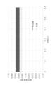
- FIG. 8 is a graph showing an example of a comparison between the estimated value and the true value of the magnet magnetic flux ⁇ am by the synchronous machine control device 1.
- the error between the estimated value and the true value of the magnet magnetic flux ⁇ am was less than 3%, and high estimation accuracy was obtained.
- FIG. 9 is a graph of another example of the comparison between the estimated value and the true value of the magnet magnetic flux ⁇ am by the synchronous machine control device 1.
- the operating state determination unit 56 in FIG. 3 determines the operating state of the synchronous machine 10 based on the magnet magnetic flux ⁇ am .
- the operating state include the ambient temperature of the synchronous machine 10, permanent magnetic flux changes (irreversible demagnetization) of the permanent magnets of the synchronous machine 10, and the presence or absence of layer shorts in the synchronous machine 10.
- the operating state determination unit 56 may determine whether the synchronous machine 10 is abnormal or normal. It is known that the magnet magnetic flux ⁇ am has a negative correlation with the temperature of the permanent magnet 10a. Further, it is known that the amount of demagnetization of the magnet magnetic flux ⁇ am has a positive correlation with the temperature of the permanent magnet 10a.
- the amount of demagnetization is a value obtained by subtracting the estimated value of the magnet magnetic flux ⁇ am at a certain point in time from the reference value of the magnet magnetic flux ⁇ am .
- the temperature of the permanent magnet 10a has a positive correlation with the ambient temperature of the synchronous machine 10. Therefore, it is possible to determine whether the ambient temperature of the synchronous machine 10 exceeds a predetermined temperature based on the magnet magnetic flux ⁇ am .
- the synchronous machine control device 1 executes a stop process to stop the synchronous machine 10 when it is determined that the ambient temperature of the synchronous machine 10 exceeds a predetermined temperature based on the magnet magnetic flux ⁇ am .
- FIG. 10 is a block diagram of a configuration example of the refrigeration cycle device 100 according to the first embodiment.
- the refrigeration cycle device 100 in FIG. 10 constitutes, for example, an air conditioner capable of cooling operation and heating operation.
- the refrigeration cycle device 100 in FIG. 10 includes a refrigeration cycle circuit 102 and a control device 101.
- the refrigeration cycle circuit 102 constitutes a flow path through which a working medium circulates.
- the working medium contains ethylene-based fluoroolefin as a refrigerant component.
- the ethylene-based fluoroolefin is preferably an ethylene-based fluoroolefin that undergoes a disproportionation reaction.
- Examples of ethylene-based fluoroolefins that cause disproportionation reactions include 1,1,2-trifluoroethylene (HFO1123), trans-1,2-difluoroethylene (HFO1132(E)), and cis-1,2-difluoroethylene.
- the working medium may contain multiple types of refrigerant components.
- the working medium may contain an ethylene-based fluoroolefin as a main refrigerant component and a compound other than the ethylene-based fluoroolefin as an auxiliary refrigerant component.
- sub-refrigerant components include hydrofluorocarbons (HFC), hydrofluoroolefins (HFO), saturated hydrocarbons, carbon dioxide, and the like.
- hydrofluorocarbons examples include difluoromethane, difluoroethane, trifluoroethane, tetrafluoroethane, pentafluoroethane, pentafluoropropane, hexafluoropropane, heptafluoropropane, pentafluorobutane, heptafluorocyclopentane, etc. It will be done.
- hydrofluoroolefins examples include monofluoropropene, trifluoropropene, tetrafluoropropene, pentafluoropropene, hexafluorobutene, and the like.
- saturated hydrocarbons examples include ethane, n-propane, cyclopropane, n-butane, cyclobutane, isobutane (2-methylpropane), methylcyclopropane, n-pentane, isopentane (2-methylbutane), neopentane (2, 2-dimethylpropane), methylcyclobutane, and the like.
- the working medium may further contain a disproportionation inhibitor that suppresses the disproportionation reaction of the ethylene-based fluoroolefin.
- disproportionation inhibitors include saturated hydrocarbons or haloalkanes.
- saturated hydrocarbons include ethane, n-propane, cyclopropane, n-butane, cyclobutane, isobutane (2-methylpropane), methylcyclopropane, n-pentane, isopentane (2-methylbutane), neopentane (2, 2-dimethylpropane), methylcyclobutane, and the like.
- n-propane is preferred.
- haloalkanes examples include haloalkanes having 1 or 2 carbon atoms and fluoroalkanes having 1 to 3 carbon atoms and having a boiling point of 0° C. or less.
- haloalkanes i.e., halomethanes
- having one carbon number include (mono)iodomethane (CH 3 I), diiodomethane (CH 2 I 2 ), dibromomethane (CH 2 Br 2 ), bromomethane (CH 3 Br), and dichloromethane.
- haloalkanes having two carbon atoms
- haloalkanes having two carbon atoms
- fluoroalkanes having 1 to 3 carbon atoms and a boiling point of 0°C or lower include fluoromethane (boiling point -78.2°C), difluoromethane (boiling point -51.6°C), and trifluoromethane (boiling point -84.4°C).
- fluoromethanes such as tetrafluoromethane (boiling point -127.8°C); fluoroethane (boiling point -37.1°C), 1,1-difluoroethane (boiling point -24.7°C), 1,1,1- Trifluoroethane (boiling point -47.2°C), 1,1,1,2-tetrafluoroethane (boiling point -26.3°C), 1,1,1,2,2-pentafluoroethane (boiling point -48.
- fluoromethanes such as tetrafluoromethane (boiling point -127.8°C); fluoroethane (boiling point -37.1°C), 1,1-difluoroethane (boiling point -24.7°C), 1,1,1- Trifluoroethane (boiling point -47.2°C), 1,1,1,2-tetrafluoroethane
- Fluoroethane such as 1-fluoropropane (boiling point -2.5°C), 2-fluoropropane (boiling point -10.0°C), 2,2-difluoropropane (boiling point -1.0°C), 1,1,1-trifluoropropane (boiling point -12.0°C), 1,1,2,2-tetrafluoropropane (boiling point -0.8°C), 1,1,1,3,3,3- Examples include fluoropropanes such as hexafluoropropane (boiling point -1.4°C).
- the working medium may include one or more saturated hydrocarbons or haloalkanes. That is, only one type of saturated hydrocarbon or haloalkane may be used, or two or more types may be used in an appropriate combination.
- the refrigeration cycle circuit 102 in FIG. 10 includes a compressor 104, a first heat exchanger 105, an expansion valve 106, a second heat exchanger 107, and a four-way valve 108.
- the refrigeration cycle device 100 in FIG. 10 includes an outdoor unit 101a and an indoor unit 101b.
- the outdoor unit 101a includes a control device 101, a compressor 104, a first heat exchanger 105, an expansion valve 106, and a four-way valve 108.
- the first heat exchanger 105 exchanges heat between the outside air and the working medium.
- the outdoor unit 101a further includes a first blower 105a for promoting heat exchange in the first heat exchanger 105.
- Indoor unit 101b includes a second heat exchanger 107.
- the second heat exchanger 107 exchanges heat between indoor air and the working medium.
- the indoor unit 101b further includes a second blower 107a for promoting heat exchange in the second heat exchanger 107.
- the compressor 104 compresses the working medium and increases the pressure of the working medium.
- the compressor 104 will be explained in detail later.
- the first heat exchanger 105 and the second heat exchanger 107 exchange heat between the working medium circulating in the refrigeration cycle circuit 102 and external air (for example, outside air or indoor air).
- the expansion valve 106 adjusts the pressure of the working medium (evaporation pressure) and the flow rate of the working medium.
- the four-way valve 108 switches the direction of the working medium circulating through the refrigeration cycle circuit 102 between a first direction corresponding to cooling operation and a second direction corresponding to heating operation.
- the first direction as shown by the solid arrow A1 in FIG. This is the direction in which the heat exchanger 107 circulates in order.
- the compressor 104 compresses and discharges the gaseous working medium, whereby the gaseous working medium is sent to the first heat exchanger 105 via the four-way valve 108.
- the first heat exchanger 105 exchanges heat between the outside air and the gaseous working medium, and the gaseous working medium is condensed and liquefied.
- the liquid working medium is depressurized by the expansion valve 106 and sent to the second heat exchanger 107 .
- heat is exchanged between the liquid working medium and indoor air, and the gaseous working medium evaporates to become a gaseous working medium.
- the gaseous working medium returns to the compressor 104 via a four-way valve 108.
- the first heat exchanger 105 functions as a condenser
- the second heat exchanger 107 functions as an evaporator. Therefore, during cooling, the indoor unit 101b blows air cooled by heat exchange in the second heat exchanger 107 into the room.
- the compressor 104 compresses and discharges the gaseous working medium, whereby the gaseous working medium is sent to the second heat exchanger 107 via the four-way valve 108.
- the second heat exchanger 107 exchanges heat between the indoor air and the gaseous working medium, and the gaseous working medium is condensed and liquefied.
- the liquid working medium is depressurized by the expansion valve 106 and sent to the first heat exchanger 105 .
- heat is exchanged between the liquid working medium and the outside air, and the gaseous working medium evaporates to become a gaseous working medium.
- the gaseous working medium returns to the compressor 104 via a four-way valve 108.
- the first heat exchanger 105 functions as an evaporator
- the second heat exchanger 107 functions as a condenser. Therefore, during heating, the indoor unit 101b blows air warmed by heat exchange in the second heat exchanger 107 into the room.
- a control device 101 in FIG. 10 controls a refrigeration cycle circuit 102. More specifically, the control device 101 controls the compressor 104, the first blower 105a, the expansion valve 106, the second blower 107a, and the four-way valve 108 of the refrigeration cycle circuit 102.
- FIG. 11 is a schematic diagram of a configuration example of the compressor 104 of the refrigeration cycle device 100.
- the compressor 104 is, for example, a hermetic compressor. Compressor 104 may be rotary, scroll, or other well-known type.
- the compressor 104 in FIG. 11 includes a closed container 140, a compression mechanism 141, and a synchronous machine 142.
- the closed container 140 in FIG. 11 constitutes a flow path for the working medium 200.
- the closed container 140 has a suction pipe 140a and a discharge pipe 140b.
- the working medium 200 is sucked into the closed container 140 through the suction pipe 140a, compressed by the compression mechanism 141, and then discharged out of the closed container 140 through the discharge pipe 140b.
- the inside of the closed container 140 is filled with a high temperature and high pressure working medium 200 and lubricating oil.
- the bottom of the closed container 140 constitutes an oil storage section that stores a mixed liquid of the working medium 200 and lubricating oil.
- the compression mechanism 141 is located within the closed container 140 and compresses the working medium 200.
- the compression mechanism 141 may have a conventionally known configuration.
- the compression mechanism 141 includes, for example, a cylinder forming a compression chamber, a rolling piston disposed in the compression chamber within the cylinder, and a crankshaft coupled to the rolling piston.
- the synchronous machine 142 is located inside the closed container 140 and operates the compression mechanism 141.
- the synchronous machine 142 is, for example, a brushless motor (three-phase brushless motor).
- the synchronous machine 142 has multiple windings (stator windings).
- the plurality of windings include a U-phase winding, a V-phase winding, and a W-phase winding.
- the synchronous machine 142 includes, for example, a rotor (permanent magnet) fixed to the crankshaft of the compression mechanism 141 and a stator provided around the rotor.
- the stator is constructed by, for example, windings (magnet wire, etc.) wound around a stator core (magnetic steel plate, etc.) through insulating paper, either in concentrated or dispersed manner.
- the winding is covered with an insulating member.
- the insulating member include polyethylene terephthalate (PET), polyethylene naphthalate (PEN), aramid polymer, polyphenylene sulfide (PPS), and the like.
- the compressor 104 may include an accumulator to prevent liquid compression in the compression chamber of the compression mechanism 141.
- the accumulator separates the working medium 200 into a gaseous working medium 200 and a liquid working medium 200, and guides only the gaseous working medium 200 into the inside of the closed container 140 from the suction pipe 140a.
- the control device 101 in FIG. 10 includes the synchronous machine drive system 4 in FIG. 1.
- the synchronous machine drive system 4 is used to drive the synchronous machine 142 of FIG. 11 instead of the synchronous machine 10 of FIG.
- the control device 101 in FIG. 10 constitutes a compression system 110 together with the compressor 104.
- the control device 101 drives the synchronous machine 142 of the compressor 104 using the synchronous machine drive system 4 .
- control device 101 drives synchronous machine 142 of compressor 104 by inputting a control command (in this embodiment, command torque T e * ) to synchronous machine drive system 4 .
- the control device 101 further controls the opening degree of the expansion valve 106, the fan rotation speed of the first blower 105a, the fan rotation speed of the second blower 107a, and switching of the four-way valve 108. .
- the operating state determination unit 56 of the synchronous machine control device 1 determines the operating state of the synchronous machine 10 based on the magnet magnetic flux ⁇ am .
- the synchronous machine control device 1 executes a stop process to stop the synchronous machine 10 when it is determined that the ambient temperature of the synchronous machine 10 exceeds a predetermined temperature based on the magnet magnetic flux ⁇ am . This makes it possible to suppress the disproportionation reaction of the working medium circulating through the refrigeration cycle circuit 102.
- the factors for the disproportionation reaction of the working medium are thought to be heat and radicals. For example, when radicals are generated under high temperature and high pressure, it is thought that a disproportionation reaction of the working medium proceeds. Radicals may be generated, for example, by a discharge phenomenon that may occur when some abnormality occurs in the compressor 104 or the drive circuit 2.
- the above-mentioned predetermined temperature is set, for example, to a temperature lower than the safe temperature of the working medium and lower than the heat-resistant temperature of the insulating member of the synchronous machine 142 of the compressor 104. obtain.
- the safe temperature of the working medium can be set based on the temperature at which a disproportionation reaction of the working medium may occur under the pressure conditions during normal operation of the refrigeration cycle device 100.
- the safe temperature of the working medium is set at 150°C.
- the heat-resistant temperature of the synchronous machine 142 of the compressor 104 is set, for example, based on the heat-resistant temperature of the insulating member of the synchronous machine 142 of the compressor 104.
- the heat resistant temperature of the insulating member of the synchronous machine 142 may be the heat resistant temperature of the insulating member having the lowest heat resistant temperature among the insulating members of the synchronous machine 142. If the operation of the refrigeration cycle device 100 is continued in a state where the internal temperature exceeds the allowable temperature limit, the insulating paper may be destroyed, and at that time, there is a high possibility that a discharge phenomenon will occur.
- the insulating member with the lowest allowable temperature limit in the synchronous machine 142 may be insulating paper between the stator core (magnetic steel plate or the like) and the stator winding (magnet wire or the like).
- the heat resistance class of the insulating paper is, for example, class E specified in JIS C 4003, the heat resistance temperature is 120°C.
- the predetermined temperature is set to a temperature lower than 120°C.
- the safety margin is preferably set to about 5° C., for example. Therefore, the predetermined temperature may be set to 115°C.
- the safety margin since it depends on the motor efficiency, it is not limited to 5°C, but may be set to a value between 0 and 20°C.
- the heat resistance class of insulating paper is not limited to class E, but may also be class B, class F, etc. If the heat resistance class is B class, the heat resistance temperature is 130°C. If the safe temperature of the working medium is 150°C, the predetermined temperature is set to a temperature lower than 130°C, for example 125°C. If the heat resistance class is F class, the heat resistance temperature is 155°C. If the safe temperature of the working medium is 150°C, the predetermined temperature is set to a temperature lower than 150°C, for example 145°C.
- the synchronous machine control device 1 continues to stop the operation of the drive circuit 2. If the ambient temperature of the synchronous machine 142 exceeds the predetermined temperature, it is considered that there is a high possibility that the disproportionation reaction of the working medium will proceed. Therefore, the synchronous machine control device 1 keeps the operation of the drive circuit 2 stopped in order to suppress the disproportionation reaction of the working medium. In this way, the synchronous machine control device 1 stops the operation of the drive circuit 2 in a state where the ambient temperature of the synchronous machine 142 is determined to exceed a predetermined temperature.
- the synchronous machine control device 1 may output an error notification indicating that there is a possibility that a disproportionation reaction may occur.
- the synchronous machine control device 1 restarts the operation of the drive circuit 2 if the ambient temperature of the synchronous machine 142 is below a predetermined temperature.
- the synchronous machine control device 1 described above is connected to a drive circuit 2 that drives the synchronous machine 10 and a detection circuit 3 that detects the current flowing through the synchronous machine 10 and outputs a detection current indicating the current.
- the synchronous machine control device 1 specifies a command voltage to be applied to the synchronous machine 10 and controls the drive circuit 2 so that the drive circuit 2 applies a voltage corresponding to the command voltage to the synchronous machine 10. It has a function of executing a magnet magnetic flux estimating process for estimating the magnet magnetic flux of the permanent magnet 10a of the synchronous machine 10.
- the synchronous machine control process specifies a command voltage so that the reactive power component of the synchronous machine 10 satisfies a predetermined condition.
- the magnet magnetic flux estimation process calculates the armature linkage flux of the synchronous machine 10, the armature reaction flux of the synchronous machine 10, and the magnet magnetic flux of the permanent magnet 10a of the synchronous machine 10 when the reactive power component of the synchronous machine 10 satisfies a predetermined condition.
- the magnet magnetic flux is estimated from the armature linkage flux obtained from the detected current and the command voltage and the armature reaction magnetic flux obtained from the inductance of the synchronous machine 10 and the detected current based on the relationship satisfied. This configuration makes it possible to improve the accuracy of estimating the magnetic flux of the permanent magnet 10a of the synchronous machine 10.
- the predetermined condition is that the reactive power component becomes zero. This configuration allows maximum torque/current control of the synchronous machine 10.
- the synchronous machine control process calculates the inner product of the magnet magnetic flux and the detected current, and executes feedback control using the inner product to control the synchronous machine 10 so that the reactive power component satisfies a predetermined condition.
- the amplitude of the command magnetic flux is specified
- the phase of the command magnetic flux is specified based on the command torque of the synchronous machine 10
- the command voltage is specified based on the amplitude and phase of the command magnetic flux.
- the synchronous machine control device 1 has a function of executing a stop process to stop the synchronous machine 10 when it is determined that the ambient temperature of the synchronous machine 10 exceeds a predetermined temperature based on the magnet magnetic flux. This configuration makes it possible to increase the safety of the operation of the synchronous machine 10.
- the compression system 110 described above includes a compressor 104 and a control device 101 that controls the compressor 104.
- the compressor 104 includes a closed container 140 that constitutes a flow path for a working medium 200 containing ethylene-based fluoroolefin as a refrigerant component, a compression mechanism 141 that is located within the closed container 140 and compresses the working medium 200, and a closed container 140.
- a synchronous machine 142 is located inside the compressor and operates a compression mechanism 141.
- the control device 101 is connected to a drive circuit 2 that drives a synchronous machine 142, a detection circuit 3 that detects a current flowing through the synchronous machine 142, and outputs a detection current indicating the current, and the drive circuit 2 and the detection circuit 3.
- a synchronous machine control device 1 is provided.
- the synchronous machine control device 1 performs a synchronous machine control process that specifies a command voltage to be applied to the synchronous machine 142 and controls the drive circuit 2 so that the drive circuit 2 applies the command voltage to the synchronous machine 142 .
- the synchronous machine control process specifies a command voltage so that the reactive power component of the synchronous machine 142 satisfies a predetermined condition.
- the magnet magnetic flux estimation process calculates that when the reactive power component of the synchronous machine 142 satisfies a predetermined condition, the armature linkage flux of the synchronous machine 142, the armature reaction magnetic flux of the synchronous machine 142, and the magnet magnetic flux of the permanent magnet of the synchronous machine 142 are Based on the relationship that is satisfied, the magnet magnetic flux is estimated from the armature linkage flux found from the detected current and command voltage and the armature reaction magnetic flux found from the inductance of the synchronous machine 142 and the detected current. This configuration allows for improved accuracy in estimating the magnetic flux of the permanent magnets of the synchronous machine 142.
- the refrigeration cycle device 100 described above includes a refrigeration cycle circuit 102 that includes a compressor 104, a condenser, an expansion valve 106, and an evaporator, in which a working medium 200 circulates, and a control device 101 that controls the refrigeration cycle circuit 102.
- Working medium 200 contains ethylene-based fluoroolefin as a refrigerant component.
- the compressor 104 includes an airtight container 140 that constitutes a flow path for the working medium 200, a compression mechanism 141 that is located inside the airtight container 140 and compresses the working medium 200, and a compression mechanism 141 that is located inside the airtight container 140 and compresses the compression mechanism 141. and a synchronous machine 142 to be operated.
- the control device 101 is connected to a drive circuit 2 that drives the synchronous machine 10, a detection circuit 3 that detects a current flowing through the synchronous machine 10, and outputs a detection current indicating the current, and the drive circuit 2 and the detection circuit 3.
- a synchronous machine control device 1 is provided.
- the synchronous machine control device 1 performs a synchronous machine control process that specifies a command voltage to be applied to the synchronous machine 142 and controls the drive circuit 2 so that the drive circuit 2 applies the command voltage to the synchronous machine 142 .
- the synchronous machine control process specifies a command voltage so that the reactive power component of the synchronous machine 142 satisfies a predetermined condition
- the magnet magnetic flux estimation process specifies a command voltage so that the reactive power component of the synchronous machine 142 satisfies a predetermined condition.
- the ethylene-based fluoroolefins include ethylene-based fluoroolefins in which a disproportionation reaction occurs. This configuration makes it possible to suppress the disproportionation reaction of the working medium 200.
- the ethylene-based fluoroolefins include 1,1,2-trifluoroethylene, trans-1,2-difluoroethylene, cis-1,2-difluoroethylene, 1,1-difluoroethylene, and tetrafluoroethylene. , or monofluoroethylene. This configuration makes it possible to suppress the disproportionation reaction of the working medium 200.
- the working medium 200 further includes difluoromethane as a refrigerant component. This configuration makes it possible to suppress the disproportionation reaction of the working medium 200.
- the working medium 200 further contains saturated hydrocarbons. This configuration makes it possible to suppress the disproportionation reaction of the working medium 200.
- the working medium 200 is a haloalkane having 1 or 2 carbon atoms or a carbon number 1 to 3 having a boiling point of 0° C. or less, as a disproportionation inhibitor that suppresses the disproportionation reaction of ethylene-based fluoroolefins. Contains fluoroalkanes. This configuration makes it possible to suppress the disproportionation reaction of the working medium 200.
- the saturated hydrocarbons include n-propane. This configuration makes it possible to suppress the disproportionation reaction of the working medium 200.
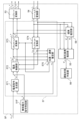
- FIG. 12 is a block diagram of the voltage generation section 5A of the synchronous machine control device according to the second embodiment.
- the voltage generation unit 5A in FIG. 12 includes a reactive power command specifying unit 51, a synchronous machine control unit 52A, an ⁇ , ⁇ /u, v, w conversion unit (two-phase three-phase coordinate conversion unit) 53, and u, w / ⁇ , ⁇ conversion unit (three-phase two-phase coordinate conversion unit) 54, a magnet magnetic flux estimation unit 55, and an operating state determination unit 56.
- the components of the voltage generation unit 5A in FIG. 12 are visual representations of processing (signal processing, etc.) executed by the synchronous machine control device, rather than an actual configuration.
- the synchronous machine control unit 52A in FIG. 12 defines signal processing corresponding to synchronous machine control processing.
- the synchronous machine control process specifies the command voltages v u * , v v * , v w * , and drives the voltages v u , v v , v w corresponding to the command voltages v u * , v v * , v w * .
- the drive circuit 2 is controlled so that the circuit 2 applies voltage to the synchronous machine 10 .
- the synchronous machine control unit 52A specifies the command voltages v u *, v v *, v w * by specifying the ⁇ -axis and ⁇ - axis command voltages V ⁇ * , V ⁇ * .
- the synchronous machine control process specifies command voltages v u * , v v * , v w * so that the reactive power component of the synchronous machine 10 satisfies predetermined conditions.
- the predetermined condition is that the reactive power component of the synchronous machine 10 matches the target value ⁇ * .
- the target value ⁇ * is set to 0. Therefore, in this embodiment, the predetermined condition is that the reactive power component becomes zero.
- the synchronous machine control unit 52A differs from the synchronous machine control unit 52 in the way it specifies the phase ⁇ s * of the command magnetic flux ⁇ s * .
- the synchronous machine control process executed by the synchronous machine control unit 52A specifies the estimated phase ⁇ s of the armature flux linkage from the armature flux linkage ( ⁇ -axis estimated magnetic flux ⁇ ⁇ and ⁇ -axis estimated magnetic flux ⁇ ⁇ ). .
- the synchronous machine control process is based on armature linkage flux ( ⁇ -axis estimated magnetic flux ⁇ ⁇ and ⁇ -axis estimated magnetic flux ⁇ ⁇ ) and detection current ( ⁇ -axis detection current i ⁇ and ⁇ -axis detection current i ⁇ ).
- the estimated torque T e of the machine 10 is specified.
- the synchronous machine control process specifies the torque phase so that the estimated torque T e matches the command torque T e * , adds the torque phase to the estimated phase ⁇ s, and specifies the phase ⁇ s * of the command magnetic flux ⁇ s * .
- This configuration makes it possible to improve the accuracy of the phase ⁇ s * of the command magnetic flux ⁇ s * .
- the synchronous machine control section 52A in FIG. , a phase identifying section 527, and a torque identifying section 528.
- the phase identifying unit 527 identifies the phase (estimated phase) ⁇ S of the armature flux linkage ⁇ S.
- the phase specifying unit 527 specifies the estimated phase ⁇ S from the armature interlinkage magnetic flux ( ⁇ -axis estimated magnetic flux ⁇ ⁇ and ⁇ -axis estimated magnetic flux ⁇ ⁇ ).
- the estimated phase ⁇ S is expressed by the following equation (20).
- the phase identification unit 527 in FIG. 12 receives the ⁇ -axis estimated magnetic flux ⁇ ⁇ and the ⁇ -axis estimated magnetic flux ⁇ ⁇ from the magnetic flux estimation unit 524.
- the phase specifying unit 527 specifies the estimated phase ⁇ S.
- the phase specifying unit 527 provides the estimated phase ⁇ S to the command phase specifying unit 525A.
- the torque specifying unit 528 specifies the torque (estimated torque) Te of the synchronous machine 10.
- the torque specifying unit 528 detects armature interlinkage magnetic fluxes ( ⁇ -axis estimated magnetic flux ⁇ ⁇ and ⁇ -axis estimated magnetic flux ⁇ ⁇ ) and detected currents ( ⁇ -axis detected current i ⁇ and ⁇ -axis detected current i ⁇ ), the estimated torque T e is specified.
- the estimated torque T e is expressed by the following equation (21). In the following equation (21), P n is the number of pole pairs of the synchronous machine 10.
- the torque identification unit 528 in FIG. 12 receives the ⁇ -axis estimated magnetic flux ⁇ ⁇ and the ⁇ -axis estimated magnetic flux ⁇ ⁇ from the magnetic flux estimation unit 524, and receives the ⁇ -axis detected current i ⁇ and the ⁇ -axis detected current i ⁇ from the u, w/ ⁇ , ⁇ conversion unit 54. Receive a detection current i ⁇ .
- the torque identifying unit 528 identifies the estimated torque T e .
- the torque specifying unit 528 provides the estimated torque T e to the command phase specifying unit 525A.
- the command phase identifying unit 525A identifies the phase ⁇ S * of the command magnetic flux ⁇ S * of the synchronous machine 10 .
- the command phase identification unit 525A receives command torque T e * as a control command.
- the command phase identification unit 525A receives the estimated phase ⁇ S from the phase identification unit 527 and receives the estimated torque T e from the torque identification unit 528.
- the command phase identifying unit 525A identifies the phase ⁇ s* based on the command torque T e * , the estimated torque T e , and the estimated phase ⁇ S.
- the command phase identifying unit 525A identifies the amount of phase correction (hereinafter referred to as torque phase) required to make the estimated torque T e match the command torque T e * .
- the command phase specifying unit 525A adds the torque phase to the estimated phase ⁇ S to specify the phase ⁇ S * .
- the predetermined condition is that the reactive power component becomes zero. This configuration allows maximum torque/current control of the synchronous machine 10.
- the synchronous machine control process specifies the estimated phase ⁇ S of the armature flux linkage from the armature flux linkage ( ⁇ -axis estimated magnetic flux ⁇ ⁇ and ⁇ -axis estimated magnetic flux ⁇ ⁇ ).
- the synchronous machine control process is based on armature linkage flux ( ⁇ -axis estimated magnetic flux ⁇ ⁇ and ⁇ -axis estimated magnetic flux ⁇ ⁇ ) and detection current ( ⁇ -axis detection current i ⁇ and ⁇ -axis detection current i ⁇ ).
- the estimated torque T e of the machine 10 is specified.
- the synchronous machine control process specifies the torque phase so that the estimated torque T e matches the command torque T e * , adds the torque phase to the estimated phase ⁇ S , and calculates the phase ⁇ S * of the command magnetic flux ⁇ S * . Identify. This configuration makes it possible to improve the accuracy of the phase ⁇ S * of the command magnetic flux ⁇ S * .
- FIG. 13 is a block diagram of the voltage generation section 5B of the synchronous machine control device according to the third embodiment.
- the voltage generation unit 5B in FIG. 13 includes a reactive power command specifying unit 51, a synchronous machine control unit 52B, an ⁇ , ⁇ /u, v, w conversion unit (two-phase three-phase coordinate conversion unit) 53, and u, w / ⁇ , ⁇ conversion unit (three-phase two-phase coordinate conversion unit) 54, a magnet magnetic flux estimation unit 55, and an operating state determination unit 56.
- the components of the voltage generation unit 5B in FIG. 13 are visual representations of processing (signal processing, etc.) executed by the synchronous machine control device, rather than an actual configuration.
- the synchronous machine control unit 52B in FIG. 13 defines signal processing corresponding to synchronous machine control processing.
- the synchronous machine control process specifies the command voltages v u * , v v * , v w * , and drives the voltages v u , v v , v w corresponding to the command voltages v u * , v v * , v w * .
- the drive circuit 2 is controlled so that the circuit 2 applies voltage to the synchronous machine 10 .
- the synchronous machine control unit 52B specifies the command voltages v u *, v v *, v w * by specifying the ⁇ -axis and ⁇ - axis command voltages V ⁇ * , V ⁇ * .
- the synchronous machine control process specifies command voltages v u * , v v * , v w * so that the reactive power component of the synchronous machine 10 satisfies predetermined conditions.
- the predetermined condition is that the reactive power component of the synchronous machine 10 matches the target value ⁇ * .
- the target value ⁇ * is set to 0. Therefore, in this embodiment, the predetermined condition is that the reactive power component becomes zero.
- the synchronous machine control unit 52B differs from the synchronous machine control unit 52 in the way it specifies the phase ⁇ S * of the command magnetic flux ⁇ S * .
- the synchronous machine control unit 52B receives the command rotation speed ⁇ ref * as a control command.
- the command rotation speed ⁇ ref * indicates a target value of the rotation speed of the rotor of the synchronous machine 10 .
- the synchronous machine control process executed by the synchronous machine control unit 52B specifies a variable for each control period of the phase of the armature interlinkage magnetic flux based on the command rotation speed ⁇ ref * , and based on the variable, the command magnetic flux ⁇ S Identify the phase ⁇ S * of * .
- the specified variable is used as the phase ⁇ S * of the command magnetic flux ⁇ S * .
- the synchronous machine control section 52B in FIG. 13 includes a command amplitude specifying section 521, a command magnetic flux specifying section 522, a voltage command specifying section 523, a magnetic flux estimating section 524, a command phase specifying section 525B, and an error variable specifying section 526. including.
- the command phase identifying unit 525B in FIG. 13 identifies the phase ⁇ S * of the command magnetic flux ⁇ S * of the synchronous machine 10.
- the command phase identification unit 525B identifies the phase ⁇ S * of the command magnetic flux ⁇ s * of the synchronous machine 10 using the command rotation speed ⁇ ref * .
- FIG. 14 is a block diagram of a configuration example of the command phase identifying section 525B.
- the command phase identification unit 525B in FIG. 14 includes an integrator 501.
- the integrator 501 specifies a variable ⁇ of the phase of the armature interlinkage flux for each control cycle based on the command rotation speed ⁇ ref * .
- the integrator 501 specifies the specified variable ⁇ as the phase ⁇ S * of the command magnetic flux ⁇ S * .
- the predetermined condition is that the reactive power component becomes zero. This configuration allows maximum torque/current control of the synchronous machine 10.
- the synchronous machine control process specifies a variable for each control cycle of the phase of the armature interlinkage magnetic flux based on the command rotation speed ⁇ ref * , and specifies the phase of the command magnetic flux based on the variable. do. This configuration allows control of the synchronous machine 10 based on magnetic flux.
- FIG. 15 is a block diagram of the voltage generation section 5C of the synchronous machine control device according to the fourth embodiment.
- the voltage generation unit 5C in FIG. 15 includes a reactive power command identification unit 51, a synchronous machine control unit 52C, an ⁇ , ⁇ /u, v, w conversion unit (two-phase three-phase coordinate conversion unit) 53, and u, w / ⁇ , ⁇ conversion unit (three-phase two-phase coordinate conversion unit) 54, a magnet magnetic flux estimation unit 55, and an operating state determination unit 56.
- the components of the voltage generation unit 5C in FIG. 15 are visual representations of processing (signal processing, etc.) executed by the synchronous machine control device, rather than an actual configuration.
- the synchronous machine control unit 52C in FIG. 15 defines signal processing corresponding to synchronous machine control processing.
- the synchronous machine control process specifies the command voltages v u * , v v * , v w * , and drives the voltages v u , v v , v w corresponding to the command voltages v u * , v v * , v w * .
- the drive circuit 2 is controlled so that the circuit 2 applies voltage to the synchronous machine 10 .
- the synchronous machine control unit 52C specifies the command voltages v u *, v v *, v w * by specifying the ⁇ -axis and ⁇ - axis command voltages V ⁇ * , V ⁇ * .
- the synchronous machine control process specifies command voltages v u * , v v * , v w * so that the reactive power component of the synchronous machine 10 satisfies predetermined conditions.
- the predetermined condition is that the reactive power component of the synchronous machine 10 matches the target value ⁇ * .
- the target value ⁇ * is set to 0. Therefore, in this embodiment, the predetermined condition is that the reactive power component becomes zero.
- the synchronous machine control unit 52C differs from the synchronous machine control unit 52 in the way it specifies the phase ⁇ S * of the command magnetic flux ⁇ S * .
- the synchronous machine control unit 52C receives the command rotation speed ⁇ ref * as a control command.
- the synchronous machine control process executed by the synchronous machine control unit 52C specifies a variable for each control cycle of the phase of the armature interlinkage magnetic flux based on the command rotation speed ⁇ ref * , and based on the variable, the command magnetic flux ⁇ s * Specify the phase ⁇ s * .
- the synchronous machine control process specifies the estimated phase ⁇ s of the armature flux linkage from the armature flux linkage ( ⁇ -axis estimated magnetic flux ⁇ ⁇ and ⁇ -axis estimated magnetic flux ⁇ ⁇ ).
- the synchronous machine control process specifies the variable ⁇ of the phase of the armature interlinkage magnetic flux for each control cycle based on the command rotational speed ⁇ ref * , and specifies the command magnetic flux ⁇ s * based on the variable ⁇ and the estimated phase ⁇ S Specify the phase ⁇ s * .
- This configuration makes it possible to improve the degree of synchronization between the rotation of the synchronous machine 10 and the rotation of the command magnetic flux.
- the synchronous machine control section 52C will be explained in more detail.
- the synchronous machine control section 52C in FIG. and a phase identifying section 527.
- the command phase specifying unit 525C in FIG. 15 specifies the phase ⁇ S * of the command magnetic flux ⁇ S * of the synchronous machine 10.
- the command phase specifying section 525C receives the estimated phase ⁇ s from the phase specifying section 527.
- the command phase identifying unit 525C identifies the phase ⁇ S * of the command magnetic flux ⁇ s * of the synchronous machine 10 using the command rotation speed ⁇ ref * and the estimated phase ⁇ S.
- FIG. 16 is a block diagram of a configuration example of the command phase identifying section 525C.
- the command phase identification unit 525C in FIG. 16 includes a multiplier 502a and an adder 502b.
- the multiplier 502a specifies the variable ⁇ of the phase of the armature interlinkage flux for each control cycle based on the command rotation speed ⁇ ref * .
- the variable ⁇ is ⁇ ref * ⁇ T S.
- the predetermined condition is that the reactive power component becomes zero. This configuration allows maximum torque/current control of the synchronous machine 10.
- the synchronous machine control process specifies the estimated phase ⁇ s of the armature flux linkage from the armature flux linkage ( ⁇ -axis estimated magnetic flux ⁇ ⁇ and ⁇ -axis estimated magnetic flux ⁇ ⁇ ).
- the synchronous machine control process specifies the variable ⁇ of the phase of the armature interlinkage magnetic flux for each control period based on the command rotational speed ⁇ ref * , and the command magnetic flux ⁇ S based on the variable ⁇ and the estimated phase ⁇ S Identify the phase ⁇ S * of * .
- FIG. 17 is a block diagram of the voltage generation section 5D of the synchronous machine control device according to the fifth embodiment.
- the voltage generation unit 5D in FIG. 17 includes a reactive power command identification unit 51, a synchronous machine control unit 52D, an ⁇ , ⁇ /u, v, w conversion unit (two-phase three-phase coordinate conversion unit) 53, and u, w / ⁇ , ⁇ conversion unit (three-phase two-phase coordinate conversion unit) 54, a magnet magnetic flux estimation unit 55, and an operating state determination unit 56.
- the components of the voltage generation unit 5D in FIG. 17 are visual representations of processing (signal processing, etc.) executed by the synchronous machine control device, rather than an actual configuration.
- the synchronous machine control unit 52D in FIG. 17 defines signal processing corresponding to synchronous machine control processing.
- the synchronous machine control process specifies the command voltages v u * , v v * , v w * , and drives the voltages v u , v v , v w corresponding to the command voltages v u * , v v * , v w * .
- the drive circuit 2 is controlled so that the circuit 2 applies voltage to the synchronous machine 10 .
- the synchronous machine control unit 52D specifies the command voltages v u *, v v *, v w * by specifying the ⁇ -axis and ⁇ - axis command voltages V ⁇ * , V ⁇ * .
- the synchronous machine control process specifies command voltages v u * , v v * , v w * so that the reactive power component of the synchronous machine 10 satisfies predetermined conditions.
- the predetermined condition is that the reactive power component of the synchronous machine 10 matches the target value ⁇ * .
- the target value ⁇ * is set to 0. Therefore, in this embodiment, the predetermined condition is that the reactive power component becomes zero.
- the synchronous machine control unit 52D differs from the synchronous machine control unit 52 in the way it specifies the phase ⁇ S * of the command magnetic flux ⁇ S * .
- the synchronous machine control process executed by the synchronous machine control unit 52D specifies the variable ⁇ of the phase of the armature interlinkage magnetic flux for each control period based on the command rotation speed ⁇ ref * , and determines the command magnetic flux based on the variable ⁇ . Identify the phase ⁇ s * of ⁇ s * .
- the synchronous machine control process is based on armature linkage flux ( ⁇ -axis estimated magnetic flux ⁇ ⁇ and ⁇ -axis estimated magnetic flux ⁇ ⁇ ) and detection current ( ⁇ -axis detection current i ⁇ and ⁇ -axis detection current i ⁇ ).
- the estimated torque T e of the synchronous machine 10 is specified.
- the synchronous machine control process specifies the variable ⁇ based on the command rotational speed ⁇ ref * and the estimated torque T e . This configuration makes it possible to improve the stability of the operation of the synchronous machine 10.
- the synchronous machine control section 52D in FIG. 17 includes a command amplitude specifying section 521, a command magnetic flux specifying section 522, a voltage command specifying section 523, a magnetic flux estimating section 524, a command phase specifying section 525D, and an error variable specifying section 526. , and a torque identifying section 528.
- the command phase identifying unit 525D in FIG. 17 identifies the phase ⁇ S * of the command magnetic flux ⁇ S * of the synchronous machine 10.
- the command phase identifying section 525D receives the estimated torque T e from the torque identifying section 528.
- the command phase identifying unit 525D identifies the phase ⁇ S * of the command magnetic flux ⁇ s * of the synchronous machine 10 using the command rotational speed ⁇ ref * and the estimated torque T e .
- FIG. 18 is a block diagram of a configuration example of the command phase identifying section 525D.
- the command phase identification unit 525D in FIG. 18 includes a high-pass filter 503a, a multiplier 503b, a subtracter 503c, and an integrator 503d.
- the high-pass filter 503a extracts and outputs a torque vibration component (torque vibration component) T H of the synchronous machine 10 from the estimated torque T e .
- the multiplier 503b multiplies the vibration component T H by a gain K 1 and outputs the result.
- the subtracter 503c subtracts the output (K 1 T H ) from the multiplier 503b from the command rotational speed ⁇ ref * and outputs the result.
- K 1 T H indicates a velocity vibration component of the synchronous machine 10.
- the integrator 503d specifies the specified variable ⁇ as the phase ⁇ S * of the command magnetic flux ⁇ S * .
- the predetermined condition is that the reactive power component becomes zero. This configuration allows maximum torque/current control of the synchronous machine 10.
- the synchronous machine control process consists of armature linkage flux ( ⁇ -axis estimated magnetic flux ⁇ ⁇ and ⁇ -axis estimated magnetic flux ⁇ ⁇ ) and detection currents ( ⁇ -axis detection current i ⁇ and ⁇ -axis detection current i ⁇ ), the estimated torque T e of the synchronous machine 10 is specified.
- the synchronous machine control process specifies the variable ⁇ based on the command rotational speed ⁇ ref * and the estimated torque T e . This configuration makes it possible to improve the stability of the operation of the synchronous machine 10.
- FIG. 19 is a block diagram of the voltage generation section 5E of the synchronous machine control device according to the sixth embodiment.
- the voltage generation unit 5E in FIG. 19 includes a reactive power command identification unit 51, a synchronous machine control unit 52E, an ⁇ , ⁇ /u, v, w conversion unit (two-phase three-phase coordinate conversion unit) 53, and u, w / ⁇ , ⁇ conversion unit (three-phase two-phase coordinate conversion unit) 54, a magnet magnetic flux estimation unit 55, and an operating state determination unit 56.
- the components of the voltage generation unit 5E in FIG. 19 are visual representations of processing (signal processing, etc.) executed by the synchronous machine control device, rather than an actual configuration.
- the synchronous machine control unit 52E in FIG. 19 defines signal processing corresponding to synchronous machine control processing.
- the synchronous machine control process specifies the command voltages v u * , v v * , v w * , and drives the voltages v u , v v , v w corresponding to the command voltages v u * , v v * , v w * .
- the drive circuit 2 is controlled so that the circuit 2 applies voltage to the synchronous machine 10 .
- the synchronous machine control unit 52E specifies the command voltages v u *, v v *, v w * by specifying the ⁇ -axis and ⁇ - axis command voltages V ⁇ * , V ⁇ * .
- the synchronous machine control process specifies command voltages v u * , v v * , v w * so that the reactive power component of the synchronous machine 10 satisfies predetermined conditions.
- the predetermined condition is that the reactive power component of the synchronous machine 10 matches the target value ⁇ * .
- the target value ⁇ * is set to 0. Therefore, in this embodiment, the predetermined condition is that the reactive power component becomes zero.
- the synchronous machine control unit 52E differs from the synchronous machine control unit 52 in the way it specifies the phase ⁇ S * of the command magnetic flux ⁇ S * .
- the synchronous machine control process executed by the synchronous machine control unit 52E specifies a variable for each control cycle of the phase of the armature interlinkage magnetic flux based on the command rotation speed ⁇ ref * , and based on the variable, the command magnetic flux ⁇ s * Specify the phase ⁇ s * .
- the synchronous machine control process is based on armature linkage flux ( ⁇ -axis estimated magnetic flux ⁇ ⁇ and ⁇ -axis estimated magnetic flux ⁇ ⁇ ) and detection current ( ⁇ -axis detection current i ⁇ and ⁇ -axis detection current i ⁇ ).
- the estimated torque T e of the synchronous machine 10 is specified.
- the synchronous machine control process specifies the variable ⁇ based on the command rotational speed ⁇ ref * and the estimated torque T e .
- the synchronous machine control process specifies the estimated phase ⁇ s of armature flux linkage from the armature flux linkage ( ⁇ -axis estimated magnetic flux ⁇ ⁇ and ⁇ -axis estimated magnetic flux ⁇ ⁇ ).
- the synchronous machine control process specifies the phase ⁇ s * of the command magnetic flux ⁇ s* based on the variable ⁇ and the estimated phase ⁇ S . This configuration makes it possible to improve the degree of synchronization between the rotation of the synchronous machine 10 and the rotation of the command magnetic flux, and to improve the stability of the operation of the synchronous machine 10.
- the synchronous machine control unit 52E in FIG. 19 includes a command amplitude identification unit 521, a command magnetic flux identification unit 522, a voltage command identification unit 523, a magnetic flux estimation unit 524, a command phase identification unit 525E, and an error variable identification unit 526. , a phase identifying section 527, and a torque identifying section 528.
- the command phase identifying unit 525E in FIG. 19 identifies the phase ⁇ S * of the command magnetic flux ⁇ S * of the synchronous machine 10.
- the command phase specifying section 525E receives the estimated phase ⁇ s from the phase specifying section 527.
- the command phase identification unit 525E receives the estimated torque T e from the torque identification unit 528.
- the command phase identification unit 525E identifies the phase ⁇ S * of the command magnetic flux ⁇ s * of the synchronous machine 10 using the command rotation speed ⁇ ref * , the estimated phase ⁇ S , and the estimated torque T e .
- FIG. 20 is a block diagram of a first configuration example of the command phase identification unit 525E (hereinafter referred to as command phase identification unit 525E1 as necessary).
- the command phase identification unit 525E1 in FIG. 20 includes a high-pass filter 504a, a multiplier 504b, a subtracter 504c, a multiplier 504d, and an adder 504e.
- the high-pass filter 504a extracts and outputs a torque vibration component (torque vibration component) T H of the synchronous machine 10 from the estimated torque T e .
- the multiplier 504b multiplies the vibration component T H by a gain K 1 and outputs the result.
- the subtracter 504c subtracts the output (K 1 T H ) from the multiplier 504b from the command rotational speed ⁇ ref * and outputs the result.
- the multiplier 504d specifies the variable ⁇ of the phase of the armature flux linkage for each control period based on the output ( ⁇ ref * ⁇ K 1 T H ) from the subtracter 504c.
- FIG. 21 is a block diagram of a second configuration example of the command phase identification unit 525E (hereinafter referred to as command phase identification unit 525E2 as necessary).
- the command phase identification unit 525E2 in FIG. 21 includes a multiplier 505a, a high-pass filter 505b, a sign inverter 505c, a PI compensator 505d, and adders 505e and 505f.
- the high-pass filter 505b extracts and outputs a torque vibration component (torque vibration component) T H of the synchronous machine 10 from the estimated torque T e .
- the sign inverter 505c multiplies the torque vibration component T H by -1 and outputs the result.
- the PI compensator 505d determines the amount of correction ( ⁇ ref * T S ) of the variable for each control cycle of the phase of the armature interlinkage flux so that the output (-T H ) from the sign inverter 505c becomes 0. do.
- FIG. 22 is a block diagram of a third configuration example of the command phase specifying section 525E (hereinafter referred to as a command phase specifying section 525E3 as necessary).
- the command phase identification unit 525E3 in FIG. 22 includes a multiplier 506a, a low-pass filter 506b, a subtracter 506c, a PI compensator 506d, and adders 506e and 506f.
- the low-pass filter 506b extracts and outputs the low frequency component T L of the torque of the synchronous machine 10 from the estimated torque T e .
- the subtracter 506c subtracts the low frequency component T L from the estimated torque T e and outputs the result.
- the output from the subtractor 506c is T L ⁇ T e , which has the same meaning as the value obtained by inverting the sign of the value of the torque vibration component T H. Therefore, subtractor 506c outputs -T H.
- the PI compensator 506d determines the amount of correction ( ⁇ ref * T S ) of the variable for each control cycle of the phase of the armature interlinkage flux so that the output (-T H ) from the subtractor 506c becomes 0. .
- the predetermined condition is that the reactive power component becomes zero. This configuration allows maximum torque/current control of the synchronous machine 10.
- the synchronous machine control process specifies a variable for each control cycle of the phase of the armature interlinkage magnetic flux based on the command rotational speed ⁇ ref * , and determines the phase of the command magnetic flux ⁇ s * based on the variable. Identify ⁇ s * .
- the synchronous machine control process is based on armature linkage flux ( ⁇ -axis estimated magnetic flux ⁇ ⁇ and ⁇ -axis estimated magnetic flux ⁇ ⁇ ) and detection current ( ⁇ -axis detection current i ⁇ and ⁇ -axis detection current i ⁇ ).
- the estimated torque T e of the synchronous machine 10 is specified.
- the synchronous machine control process specifies the variable ⁇ based on the command rotational speed ⁇ ref * and the estimated torque T e .
- the synchronous machine control process specifies the estimated phase ⁇ s of armature flux linkage from the armature flux linkage ( ⁇ -axis estimated magnetic flux ⁇ ⁇ and ⁇ -axis estimated magnetic flux ⁇ ⁇ ).
- the synchronous machine control process specifies the phase ⁇ s * of the command magnetic flux ⁇ s* based on the variable ⁇ and the estimated phase ⁇ S . This configuration makes it possible to improve the degree of synchronization between the rotation of the synchronous machine 10 and the rotation of the command magnetic flux, and to improve the stability of the operation of the synchronous machine 10.
- FIG. 23 is a block diagram of the voltage generation section 5F of the synchronous machine control device 1 according to the seventh embodiment.
- the voltage generation unit 5F in FIG. 23 includes a reactive power command identification unit 51F, an ⁇ , ⁇ /u, v, w conversion unit (two-phase three-phase coordinate conversion unit) 53, and a u, w/ ⁇ , ⁇ conversion unit ( A three-phase two-phase coordinate conversion section) 54, a magnet flux estimating section 55, an operating state determining section 56, a synchronous machine control section 57, and a magnetic flux estimating section 58 are included.
- the components of the voltage generation unit 5F in FIG. 23 are visual representations of processing (signal processing, etc.) executed by the synchronous machine control device, rather than an actual configuration.
- the synchronous machine control unit 57 in FIG. 23 defines signal processing corresponding to synchronous machine control processing.
- the synchronous machine control process specifies the command voltages v u * , v v * , v w * , and drives the voltages v u , v v , v w corresponding to the command voltages v u * , v v * , v w * .
- the drive circuit 2 is controlled so that the circuit 2 applies voltage to the synchronous machine 10 .
- the synchronous machine control unit 57 specifies the command voltages v u *, v v *, v w * by specifying the dm axis and qm axis command voltages V dm * , V qm * , which will be described later. do. That is, the command voltages v u * , v v * , v w * are specified by the dm axis and qm axis command voltages V dm * , V qm * .
- the operation of the synchronous machine control device 1 is based on a UVW coordinate system (UVW coordinate axis), an ⁇ coordinate system ( ⁇ coordinate axis), a dq coordinate system (dq coordinate axis), a dmqm coordinate system (dmqm coordinate axis), and a ⁇ coordinate system. It can be explained using a coordinate system ( ⁇ coordinate axis).
- FIG. 24 is an explanatory diagram of a coordinate system used in the synchronous machine control device.
- angle means an electrical angle.
- the ⁇ coordinate system in FIG. 24 is a rotating coordinate system based on the rotor (permanent magnet 10a) of the synchronous machine 10.
- the ⁇ coordinate system is also called an estimated coordinate system.
- the ⁇ coordinate system is a two-dimensional orthogonal coordinate system and is defined by a ⁇ axis and a ⁇ axis that are orthogonal to each other.
- the ⁇ coordinate system is defined as a coordinate system that rotates at an arbitrary rotational speed (number of rotations).
- ⁇ dm indicates the angle of the dmqm coordinate system with respect to the ⁇ coordinate system
- ⁇ m indicates the angle of the dq coordinate system with respect to the dmqm coordinate system.
- FIG. 24 is a rotating coordinate system based on the rotor (permanent magnet 10a) of the synchronous machine 10.
- the ⁇ coordinate system is also called an estimated coordinate system.
- the ⁇ coordinate system is a two-dimensional orthogonal coordinate system and is defined by a
- ⁇ ⁇ indicates the angle of the dq coordinate system with respect to the ⁇ coordinate system
- ⁇ m indicates the angle of the dmqm coordinate system with respect to the ⁇ coordinate system.
- ⁇ is the rotational speed of the synchronous machine 10.
- ⁇ ⁇ is the rotation speed of the ⁇ coordinate system.
- i dm * is the dm-axis component of the command current in the dmqm coordinate system, and hereinafter may be referred to as dm-axis command current.
- i qm * is the qm-axis component of the command current in the dmqm coordinate system, and hereinafter may be referred to as qm-axis command current.
- v dm * is the dm-axis component of the command voltage in the dmqm coordinate system, and hereinafter may be referred to as dm-axis command voltage.
- v qm * is the qm-axis component of the command voltage in the dmqm coordinate system, and hereinafter may be referred to as qm-axis command voltage.
- i dm is a dm-axis component of the detected current in the dmqm coordinate system, and hereinafter may be referred to as dm-axis current.
- i qm is a qm-axis component of a detected current in a dmqm coordinate system, and is sometimes referred to as a qm-axis current hereinafter.
- ⁇ e is the estimated rotational speed of the synchronous machine 10.
- v ⁇ * is the ⁇ -axis component of the command voltage in the ⁇ coordinate system, and hereinafter may be referred to as ⁇ -axis command voltage.
- v ⁇ * is the ⁇ -axis component of the command voltage in the ⁇ coordinate system, and hereinafter may be referred to as ⁇ -axis command voltage.
- i ⁇ is the ⁇ -axis component of the detection current in the ⁇ coordinate system, and may be hereinafter referred to as ⁇ -axis detection current.
- i ⁇ is the ⁇ -axis component of the detected current in the ⁇ coordinate system, and may be hereinafter referred to as the ⁇ -axis detected current.
- ⁇ ⁇ is the ⁇ -axis component of the estimated armature interlinkage magnetic flux in the ⁇ coordinate system, and hereinafter may be referred to as ⁇ -axis estimated magnetic flux.
- ⁇ ⁇ is the ⁇ -axis component of the estimated armature interlinkage magnetic flux in the ⁇ coordinate system, and hereinafter may be referred to as ⁇ -axis estimated magnetic flux.
- ⁇ ref * is a command rotation speed as a control command. The command rotation speed ⁇ ref * can be given to the synchronous machine control device 1 from an external device.
- the reactive power command specifying unit 51F in FIG. 23 specifies the target value of the reactive power component of the synchronous machine 10.
- the reactive power component of the synchronous machine 10 is given by the inner product of the magnetic flux of the permanent magnet 10a of the synchronous machine 10 and the current flowing through the synchronous machine 10.
- the reactive power component of the synchronous machine 10 is expressed by the above equation (5).
- the reactive power component ⁇ can be specified by the dm-axis current i dm .
- the reactive power command specifying unit 51F in FIG. 23 designates the dm-axis command current i dm * as the target value of the reactive power component.
- the dm-axis command current i dm * indicates the target value of the dm-axis current i dm .
- the dm-axis command current i dm * is set to 0 in the dmqm coordinate system. This is equivalent to setting the target value of the reactive power component of the synchronous machine 10 to zero.
- the synchronous machine control process specifies command voltages v u * , v v * , v w * so that the reactive power component of the synchronous machine 10 satisfies predetermined conditions.
- the predetermined condition is that the reactive power component of the synchronous machine 10 matches a target value.
- the target value is set to zero. Therefore, in this embodiment, the predetermined condition is that the reactive power component becomes zero.
- the synchronous machine control unit 57 in FIG. 23 includes a current command generation unit 571, a current control unit 572, a dm, qm/ ⁇ , ⁇ conversion unit 573, an ⁇ , ⁇ /dm, qm conversion unit 574, and a position/velocity and an estimator 575.
- the current command generation unit 571 generates (specifies) the qm-axis component of the command current (qm-axis command current) i qm * .
- the current command generation unit 571 specifies the qm-axis command current i qm * from the command rotation speed ⁇ ref * and the estimated rotation speed ⁇ e of the synchronous machine 10 .
- the current command generation unit 571 in FIG. 23 receives the command rotation speed ⁇ ref * from the outside, and receives the estimated rotation speed ⁇ e from the position/speed estimation unit 575.
- the current command generation unit 571 specifies the qm-axis command current i qm * .
- the current command generation unit 571 provides the qm-axis command current i qm * to the current control unit 572.
- the current control unit 572 specifies the dm-axis command voltage v dm * and the qm-axis command voltage v qm * .
- the current control unit 572 calculates the dm-axis command voltage v from the dm-axis command current i dm * , the qm-axis command current i qm * , the dm-axis current i dm , and the qm-axis current i qm . dm * and the qm-axis command voltage v qm * .
- the current control unit 572 in FIG. 23 receives the qm-axis command current i qm * from the current command generation unit 571, receives the dm-axis command current i dm * from the reactive power command identification unit 51F, and performs ⁇ , ⁇ /dm, qm conversion.
- the dm-axis current i dm and the qm-axis current i qm are received from the unit 574 .
- the current control unit 572 specifies the dm-axis command voltage v dm * and the qm-axis command voltage v qm * .
- the current control unit 572 provides the dm-axis command voltage v dm * and the qm-axis command voltage v qm * to the dm, qm/ ⁇ , ⁇ conversion unit 573 and the position/velocity estimation unit 575.
- the dm, qm/ ⁇ , ⁇ conversion unit 573 converts the dm-axis command voltage v dm * and the qm-axis command voltage v qm * in the dmqm coordinate system into the ⁇ -axis command voltage v ⁇ * and the ⁇ -axis command in the ⁇ coordinate system. Convert to voltage v ⁇ * .
- the ⁇ -axis command voltage v ⁇ * is expressed by the following equation (25)
- the ⁇ -axis command voltage v ⁇ * is expressed by the following equation (26).
- the dm, qm/ ⁇ , ⁇ conversion unit 573 in FIG. 23 receives the dm-axis command voltage v dm * and the qm-axis command voltage v qm * from the current control unit 572, and receives the estimated phase ⁇ dm from the position/velocity estimation unit 575. receive.
- the dm, qm/ ⁇ , ⁇ converter 573 specifies the ⁇ -axis command voltage v ⁇ * and the ⁇ -axis command voltage v ⁇ * .
- the dm, qm/ ⁇ , ⁇ converter 573 provides the ⁇ -axis command voltage v ⁇ * and the ⁇ -axis command voltage v ⁇ * to the ⁇ , ⁇ /u, v, w converter 53 and the magnetic flux estimator 58 .
- the ⁇ , ⁇ /dm, qm conversion unit 574 converts the ⁇ -axis detected current i ⁇ and the ⁇ -axis detected current i ⁇ in the ⁇ coordinate system into the dm-axis current i dm and the qm-axis current i qm in the dmqm coordinate system. do.
- the dm-axis current i dm is expressed by the following equation (27)
- the qm-axis current i qm is expressed by the following equation (28).
- the ⁇ , ⁇ / dm, qm conversion unit 574 in FIG . Receives the phase ⁇ dm .
- the ⁇ , ⁇ /dm, qm conversion unit 574 specifies the dm-axis current i dm and the qm-axis current i qm .
- the ⁇ , ⁇ /dm, qm conversion unit 574 provides the dm-axis current i dm and the qm-axis current i qm to the current control unit 572 and the position/velocity estimating unit 575 .
- the position/speed estimation unit 575 specifies the estimated phase ⁇ dm of the synchronous machine 10 and the estimated rotational speed ⁇ e of the synchronous machine 10.
- the position/speed estimating unit 575 calculates the estimated phase ⁇ dm and estimated rotation from the dm-axis command voltage v dm * , the qm-axis command voltage v qm * , the dm-axis current i dm , and the qm -axis current i qm .
- ⁇ is the rotational speed of the synchronous machine 10
- R a is the resistance of the synchronous machine 10
- L d is the d-axis inductance of the synchronous machine 10
- L q is the q-axis inductance of the synchronous machine 10
- p is the differential operation. It is a child.
- L dm is expressed by the following expression (30)
- L qm is expressed by the following expression (31)
- ⁇ m is expressed by the following expression (32)
- ⁇ am is expressed by the following expression (33).
- ⁇ a is the magnetic flux of the permanent magnet 10a in the dq coordinate system.
- Equation (34) v ⁇ and v ⁇ are the ⁇ and ⁇ axis components of the voltage of the synchronous machine 10, and i ⁇ and i ⁇ are the ⁇ and ⁇ axis components of the current of the synchronous machine 10.
- e ⁇ and e ⁇ represent extended induced voltages, which are expressed by the following equation (35).
- Equation (35) E exm is expressed by the following equation (36).
- the angle ⁇ m is the angle of the dmqm coordinate system with respect to the ⁇ coordinate system, and means the axis error between the ⁇ coordinate system and the dmqm coordinate system.
- the angle ⁇ m is expressed by the following equation (37) from the angle ⁇ ⁇ of the dq coordinate system with respect to the ⁇ coordinate system and the angle ⁇ m of the dq coordinate system with respect to the dmqm coordinate system.
- the angle ⁇ m is expressed by the following equation (38) using the extended induced voltages e ⁇ and e ⁇ .
- equation (39) is expressed by the following equation (40).
- the rotation speed ⁇ ⁇ of the ⁇ coordinate system when ⁇ m becomes 0 can be set as the estimated rotation speed ⁇ e of the synchronous machine 10.
- the position/speed estimating unit 575 specifies the estimated rotational speed ⁇ e by feedback control so that the angle (ie, axis error) ⁇ m of the dmqm coordinate system with respect to the ⁇ coordinate system becomes 0.
- the estimated rotational speed ⁇ e is expressed by the following equation (41).
- K P is a proportional gain
- K I is an integral gain
- s is a Laplace operator.
- the estimated phase ⁇ dm of the synchronous machine 10 can be determined by time integration of the estimated rotational speed ⁇ e of the synchronous machine 10. Therefore, the estimated phase ⁇ dm is expressed by the following equation (42).
- s is a Laplace operator.
- the position /speed estimation unit 575 calculates the angle ( In other words, the axis error) ⁇ m is specified.
- the position/speed estimation unit 575 specifies the estimated rotational speed ⁇ e by feedback control so that the axis error ⁇ m becomes 0.
- the position/speed estimation unit 575 specifies the estimated phase ⁇ dm from the estimated rotational speed ⁇ e by integration.
- the position/velocity estimation unit 575 in FIG. 23 receives the dm-axis command voltage v dm * and the qm-axis command voltage v qm * from the current control unit 572, and receives the dm-axis current i dm from the ⁇ , ⁇ /dm, qm conversion unit 574. and receives the qm-axis current i qm .
- the position/speed estimation unit 575 specifies the estimated rotational speed ⁇ e and the estimated phase ⁇ dm .
- the position/speed estimation unit 575 provides the estimated rotational speed ⁇ e to the current command generation unit 571.
- the position/velocity estimation unit 575 provides the estimated phase ⁇ dm to the dm, qm/ ⁇ , ⁇ conversion unit 573 and the ⁇ , ⁇ /dm, qm conversion unit 574.
- the synchronous machine control process is performed using a dm-axis command voltage v dm * and a qm-axis command in a dmqm coordinate system defined by a dm-axis corresponding to the direction of magnet magnetic flux and a qm-axis perpendicular to the dm-axis.
- the command voltages v u * , v v * , v w * are specified based on the voltage v qm *.
- the synchronous machine control process converts the detected current into a dm-axis current i dm and a qm-axis current i qm in a dmqm coordinate system.
- the synchronous machine control process executes feedback control using the dm-axis current i dm and the qm-axis current i qm to adjust the dm-axis command voltage v dm * and the qm-axis command so that the reactive power component satisfies a predetermined condition. Identify the voltage v qm * .
- the synchronous machine control process calculates the estimated phase ⁇ of the permanent magnet 10a from the dm-axis command voltage v dm * and the qm-axis command voltage v qm * , and the dm-axis current i dm and the qm-axis current i qm .
- the estimated phase ⁇ dm is used to convert the detected current into a dm-axis current i dm and a qm-axis current i qm in the dmqm coordinate system.
- the synchronous machine control process specifies the qm-axis command current i qm * in the dmqm coordinate system by executing feedback control using the estimated rotational speed ⁇ e .
- the synchronous machine control process specifies the dm-axis command voltage v dm * and the qm-axis command voltage v qm * based on the qm-axis command current i qm * so that the reactive power component satisfies a predetermined condition. This configuration allows control of the synchronous machine 10 based on current.
- the magnetic flux estimation unit 58 in FIG. 23 estimates the armature linkage magnetic flux ⁇ S of the synchronous machine 10.
- the magnetic flux estimation unit 58 calculates the ⁇ -axis estimated magnetic flux ⁇ ⁇ and the ⁇ -axis estimated magnetic flux ⁇ ⁇ . More specifically, the magnetic flux estimation unit 58 calculates the ⁇ -axis estimated magnetic flux from the ⁇ -axis command voltage v ⁇ * , the ⁇ -axis command voltage v ⁇ * , the ⁇ -axis detection current i ⁇ , and the ⁇ -axis detection current i ⁇ .
- ⁇ ⁇ and ⁇ -axis estimated magnetic flux ⁇ ⁇ are calculated.
- the ⁇ -axis estimated magnetic flux ⁇ ⁇ and the ⁇ -axis estimated magnetic flux ⁇ ⁇ are expressed by the above equations (11) and (12), respectively.
- the magnetic flux estimation unit 58 in FIG. 23 receives the ⁇ -axis command voltage v ⁇ * and the ⁇ -axis command voltage v ⁇ * from the dm, qm/ ⁇ , ⁇ conversion unit 573 and Axis detection current i ⁇ and ⁇ axis detection current i ⁇ are received.
- the magnetic flux estimation unit 58 calculates the ⁇ -axis estimated magnetic flux ⁇ ⁇ and the ⁇ -axis estimated magnetic flux ⁇ ⁇ .
- the magnetic flux estimation unit 58 provides the ⁇ -axis estimated magnetic flux ⁇ ⁇ and the ⁇ -axis estimated magnetic flux ⁇ ⁇ to the magnet magnetic flux estimation unit 55 .
- the magnet magnetic flux estimator 55 in FIG. 23 receives the ⁇ -axis estimated magnetic flux ⁇ ⁇ and the ⁇ -axis estimated magnetic flux ⁇ ⁇ from the magnetic flux estimator 58, and receives the ⁇ -axis detected current i ⁇ and ⁇ from the u, w/ ⁇ , ⁇ converter 54. Receive the axis detection current i ⁇ .
- the magnet magnetic flux estimation unit 55 calculates the magnet magnetic flux from the above equation (1) using the ⁇ -axis estimated magnetic flux ⁇ ⁇ , the ⁇ -axis estimated magnetic flux ⁇ ⁇ , the ⁇ -axis detected current i ⁇ , and the ⁇ -axis detected current i ⁇ . Estimate ⁇ am .
- the magnet magnetic flux estimating section 55 provides the magnet magnetic flux ⁇ am to the operating state determining section 56 .
- the synchronous machine control processing is performed using the dm-axis command voltage v dm * and The command voltages v u * , v v * , v w * are specified based on the qm-axis command voltage v qm * .
- the synchronous machine control process converts the detected current into a dm-axis current i dm and a qm-axis current i qm in a dmqm coordinate system.
- the synchronous machine control process calculates the estimated phase ⁇ dm and estimated rotational speed ⁇ of the permanent magnet 10a from the dm-axis command voltage v dm * and the qm-axis command voltage v qm * , and the dm-axis current i dm and the qm -axis current i qm. Specify e .
- the synchronous machine control process specifies the qm-axis command current i qm * in the dmqm coordinate system by executing feedback control using the estimated rotational speed ⁇ e .
- the synchronous machine control process specifies the dm-axis command voltage v dm * and the qm-axis command voltage v qm * based on the qm-axis command current i qm * so that the reactive power component satisfies a predetermined condition.
- This configuration allows control of the synchronous machine 10 based on current.
- FIG. 25 is a block diagram of the voltage generation section 5G of the synchronous machine control device according to the eighth embodiment.
- the voltage generation unit 5G in FIG. 25 includes a reactive power command specifying unit 51G, a synchronous machine control unit 52G, an ⁇ , ⁇ /u, v, w conversion unit (two-phase three-phase coordinate conversion unit) 53, and u, w / ⁇ , ⁇ conversion unit (three-phase two-phase coordinate conversion unit) 54, a magnet magnetic flux estimation unit 55G, an operating state determination unit 56, and a dm-axis current estimation unit 59.
- the components of the voltage generation unit 5G in FIG. 25 are visual representations of processing (signal processing, etc.) executed by the synchronous machine control device, rather than an actual configuration.
- the reactive power command specifying unit 51G in FIG. 25 specifies the target value ⁇ * of the reactive power component of the synchronous machine 10.
- the target value ⁇ * is given to the synchronous machine control section 52G.
- the target value ⁇ * is set to achieve flux weakening control rather than maximum torque/current control.
- Flux weakening control is also called field weakening control or voltage phase control.
- an induced voltage proportional to the rotation speed is generated by the magnetic flux of the permanent magnet of the rotor. When the induced voltage exceeds the output voltage of the synchronous machine control device as the rotational speed increases, current cannot flow through the stator windings, and the rotational speed cannot be increased further.
- the dm-axis current i dm is set not to 0 but to a negative value. This has the effect of weakening the magnetic flux of the rotor's permanent magnets, lowering the induced voltage and making it possible to drive at higher rotational speeds.
- the target value ⁇ * of the reactive power component of the synchronous machine 10 is set to a predetermined value (negative predetermined value) that is greater than or equal to a predetermined lower limit value and less than 0.
- the absolute value of the predetermined lower limit value is, for example, the product of the rated current of the synchronous machine 10 and the rated magnetic flux of the permanent magnet 10a.
- FIG. 26 is an explanatory diagram of the current/magnetic flux vector of the synchronous machine 10.
- FIG. 26 shows the armature linkage magnetic flux of the synchronous machine 10 and the electric machine
- ⁇ S is the armature linkage flux (vector) of the synchronous machine 10.
- ⁇ S ( ⁇ dm , ⁇ qm ).
- ⁇ am is the magnetic flux (vector) of the permanent magnet 10a.
- ⁇ am is the magnetic flux (vector) of the permanent magnet 10a in the dmqm coordinate system.
- L qm is a virtual inductance and means the inductance of the qm axis in the dmqm coordinate system.
- ia is a current (that is, a detected current) (vector) flowing through the synchronous machine 10.
- ia ( idm , iqm ).
- i dm ⁇ 0.
- the armature reaction magnetic flux of the synchronous machine 10 is represented by L qm i a .
- the synchronous machine control unit 52G in FIG. 25 defines signal processing corresponding to synchronous machine control processing.
- the synchronous machine control process specifies the command voltages v u * , v v * , v w * , and drives the voltages v u , v v , v w corresponding to the command voltages v u * , v v * , v w * .
- the drive circuit 2 is controlled so that the circuit 2 applies voltage to the synchronous machine 10 .
- the synchronous machine control unit 52G specifies the command voltages v u *, v v *, v w * by specifying the ⁇ -axis and ⁇ - axis command voltages V ⁇ * , V ⁇ * .
- the synchronous machine control process specifies command voltages v u * , v v * , v w * so that the reactive power component of the synchronous machine 10 satisfies predetermined conditions.
- the predetermined condition is that the reactive power component of the synchronous machine 10 matches the target value ⁇ * .
- the target value ⁇ * is set to a predetermined value (negative predetermined value) that is greater than or equal to a predetermined lower limit value and less than 0. Therefore, in the present embodiment, the predetermined condition is that the reactive power component is a predetermined value (negative predetermined value) greater than or equal to the predetermined lower limit value and less than 0.
- the synchronous machine control section 52G in FIG. 25 includes a command amplitude specifying section 521, a command magnetic flux specifying section 522, a voltage command specifying section 523, a magnetic flux estimating section 524, a command phase specifying section 525, and an error variable specifying section 526. including.
- the magnetic flux estimation unit 524 adds the ⁇ -axis estimated magnetic flux ⁇ ⁇ and the ⁇ -axis estimated magnetic flux ⁇ ⁇ to the voltage command identification unit 523, the error variable identification unit 526, and the magnet flux estimation unit 55G. It is also provided to the dm-axis current estimation section 59.
- the dm-axis current estimation unit 59 defines signal processing corresponding to dm-axis current identification processing.
- the dm-axis current specifying process specifies a dm-axis current i dm in a dmqm coordinate system defined by a dm axis corresponding to the direction of the magnet magnetic flux ⁇ am and a qm axis orthogonal to the dm axis.
- the dm-axis current identification process uses armature linkage magnetic flux ⁇ S ( ⁇ -axis estimated magnetic flux ⁇ ⁇ and ⁇ -axis estimated magnetic flux ⁇ ⁇ ), detection current i a ( ⁇ -axis detected current i ⁇ and ⁇ -axis detected current i ⁇ ), and The position (angle ⁇ dm ) of the permanent magnet 10a in the dmqm coordinate system is estimated from , and the position (angle ⁇ dm ) of the permanent magnet 10a and the detection current i a ( ⁇ -axis detection current i ⁇ and ⁇ -axis detection current i ⁇ ) The dm-axis current i dm is specified from .
- FIG. 27 is a block diagram of a configuration example of the dm-axis current estimation section 59.
- the dm-axis current estimating section 59 in FIG. 27 includes a magnet magnetic flux specifying section 591, a magnet phase specifying section 592, and an ⁇ , ⁇ /dm converting section 593.
- the magnet magnetic flux identification unit 591 determines the ⁇ -axis magnet magnetic flux ⁇ am_ ⁇ and the ⁇ -axis magnet from the ⁇ -axis estimated magnetic flux ⁇ ⁇ , the ⁇ -axis estimated magnetic flux ⁇ ⁇ , the ⁇ -axis detected current i ⁇ , and the ⁇ -axis detected current i ⁇ . Specify the magnetic flux ⁇ am_ ⁇ .
- the ⁇ -axis magnet magnetic flux ⁇ am_ ⁇ is expressed by the above equation (14), and the ⁇ -axis magnet magnetic flux ⁇ am_ ⁇ is expressed by the above equation (15).
- the magnet magnetic flux identification unit 591 in FIG. 27 receives the ⁇ -axis estimated magnetic flux ⁇ ⁇ and the ⁇ -axis estimated magnetic flux ⁇ ⁇ from the magnetic flux estimation unit 524, and receives the ⁇ -axis detected current i ⁇ and ⁇ from the u, w/ ⁇ , ⁇ conversion unit 54. Receive the axis detection current i ⁇ .
- the magnet magnetic flux identification unit 591 identifies the ⁇ -axis magnet magnetic flux ⁇ am_ ⁇ and the ⁇ -axis magnet magnetic flux ⁇ am_ ⁇ .
- the magnet magnetic flux identification unit 591 provides the ⁇ -axis magnet magnetic flux ⁇ am_ ⁇ and the ⁇ -axis magnet magnetic flux ⁇ am_ ⁇ to the magnet phase identification unit 592 .
- the magnet phase identifying unit 592 identifies the angle ⁇ dm as the magnet phase from the ⁇ -axis magnet magnetic flux ⁇ am_ ⁇ and the ⁇ -axis magnet magnetic flux ⁇ am_ ⁇ .
- the angle ⁇ dm is expressed by the following equation (45).
- the magnet phase specifying unit 592 in FIG. 27 receives the ⁇ -axis magnet magnetic flux ⁇ am_ ⁇ and the ⁇ -axis magnet magnetic flux ⁇ am_ ⁇ from the magnet magnetic flux specifying unit 591.
- the magnet phase identifying unit 592 identifies the angle ⁇ dm as the magnet phase.
- the magnet phase specifying unit 592 provides the angle ⁇ dm to the ⁇ , ⁇ /dm converting unit 593.
- the ⁇ , ⁇ /dm conversion unit 593 specifies the dm-axis current i dm from the ⁇ -axis detection current i ⁇ , the ⁇ -axis detection current i ⁇ , and the angle ⁇ dm .
- the dm-axis current i dm is expressed by the above equation (27).
- the ⁇ , ⁇ / dm conversion unit 593 in FIG . receive.
- the ⁇ , ⁇ /dm conversion unit 593 specifies the dm-axis current i dm .
- the ⁇ , ⁇ /dm converter 593 provides the dm-axis current i dm to the magnet magnetic flux estimator 55G.
- the dm - axis current estimator 59 in FIG. A current i ⁇ and a ⁇ -axis detection current i ⁇ are received.
- the dm-axis current estimation unit 59 specifies the dm-axis current i dm .
- the dm-axis current estimator 59 provides the dm-axis current i dm to the magnet magnetic flux estimator 55G.
- the magnet flux estimation unit 55G in FIG. 25 defines signal processing corresponding to magnet flux estimation processing.
- the magnet magnetic flux estimating process estimates the magnet magnetic flux ⁇ am of the permanent magnet 10a of the synchronous machine 10.
- the predetermined condition is that the reactive power component becomes a predetermined value (negative predetermined value) greater than or equal to a predetermined lower limit value and less than 0.
- the reactive power component ⁇ is expressed by the following equation (46) from the above equations (2), (43), and (44).
- the magnet magnetic flux ⁇ am is expressed by the following equation (47) from the above equation (46).
- equation (47) Since the dm-axis inductance L dm is very small, the second term on the right side of equation (47) can be set to 0, and the above equation (47) can be rewritten as the following equation (48).
- the reactive power component ⁇ is also expressed by the following equation (49) from the ⁇ -axis estimated magnetic flux ⁇ ⁇ , the ⁇ -axis estimated magnetic flux ⁇ ⁇ , the ⁇ -axis detected current i ⁇ , and the ⁇ -axis detected current i ⁇ .
- the magnet magnetic flux estimating unit 55G estimates the magnet magnetic flux ⁇ am from the relational expression (50) derived from the relationship of equation (44). As is clear from equation (50), equation (50) is a calculation using magnetic flux and does not include the command voltage and the winding resistance itself. Therefore, it is less susceptible to voltage errors. Therefore, it is possible to improve the accuracy of estimating the magnetic flux of the permanent magnet 10a of the synchronous machine 10.
- the magnet magnetic flux estimator 55G receives the ⁇ -axis estimated magnetic flux ⁇ ⁇ and the ⁇ -axis estimated magnetic flux ⁇ ⁇ from the magnetic flux estimator 524, and receives the ⁇ -axis detected current i from the u, w/ ⁇ , ⁇ converter 54. It receives the ⁇ and ⁇ axis detection currents i ⁇ , and receives the dm axis current i dm from the dm axis current estimator 59.
- the magnet magnetic flux estimating unit 55G uses the ⁇ -axis estimated magnetic flux ⁇ ⁇ , the ⁇ -axis estimated magnetic flux ⁇ ⁇ , the ⁇ -axis detection current i ⁇ , the ⁇ -axis detection current i ⁇ , and the dm-axis current i dm .
- the magnet magnetic flux ⁇ am is estimated from equation (50).
- the magnet magnetic flux estimation section 55G provides the magnet magnetic flux ⁇ am to the operating state determination section 56.
- FIG. 28 is a graph showing an example of a comparison between the estimated value and the true value of the magnet magnetic flux ⁇ am by the synchronous machine control device.
- the error between the estimated value and the true value of the magnet magnetic flux ⁇ am was less than 8%, and high estimation accuracy was obtained.
- FIG. 29 is a graph of another example of comparison between the estimated value and the true value of the magnet magnetic flux ⁇ am by the synchronous machine control device.
- the predetermined condition is that the reactive power component reaches a predetermined value that is greater than or equal to a predetermined lower limit value and less than zero.
- the absolute value of the predetermined lower limit value is the product of the rated current of the synchronous machine 10 and the rated magnetic flux of the permanent magnet 10a. This configuration allows weakening current control of the synchronous machine 10.
- the synchronous machine control process calculates the inner product of the magnet magnetic flux and the detected current, and executes feedback control using the inner product to control the synchronous machine 10 so that the reactive power component satisfies a predetermined condition.
- the amplitude of the command magnetic flux is specified, the phase of the command magnetic flux is specified based on the command torque of the synchronous machine 10, and the command voltage is specified based on the amplitude and phase of the command magnetic flux.
- the synchronous machine control device has a function of executing dm axis current specifying processing.
- the dm-axis current specifying process specifies a dm-axis current i dm in a dmqm coordinate system defined by a dm axis corresponding to the direction of the magnet magnetic flux ⁇ am and a qm axis orthogonal to the dm axis.
- the dm-axis current identification process uses armature linkage magnetic flux ⁇ S ( ⁇ -axis estimated magnetic flux ⁇ ⁇ and ⁇ -axis estimated magnetic flux ⁇ ⁇ ), detection current i a ( ⁇ -axis detected current i ⁇ and ⁇ -axis detected current i ⁇ ), and The position (angle ⁇ dm ) of the permanent magnet 10a in the dmqm coordinate system is estimated from , and the position (angle ⁇ dm ) of the permanent magnet 10a and the detection current i a ( ⁇ -axis detection current i ⁇ and ⁇ -axis detection current i ⁇ ) The dm-axis current i dm is specified from .
- the magnet magnetic flux estimation process calculates the armature linkage magnetic flux ⁇ S of the synchronous machine 10 expressed by equation (44), the armature reaction magnetic flux L qmi a of the synchronous machine 10, and the magnet magnetic flux of the permanent magnet 10a of the synchronous machine 10.
- the magnet magnetic flux ⁇ am is estimated from the relational expression between the magnet magnetic flux ⁇ am , the reactive power component ⁇ , and the dm-axis current i dm , which is derived from the relationship satisfied by ⁇ am and is expressed by equation ( 50) . This configuration allows control of the synchronous machine (10) based on magnetic flux.
- FIG. 30 is a block diagram of the voltage generation section 5H of the synchronous machine control device according to the ninth embodiment.
- the voltage generating section 5H in FIG. 30 includes a reactive power command specifying section 51, a synchronous machine control section 52H, an ⁇ , / ⁇ , ⁇ conversion unit (three-phase two-phase coordinate conversion unit) 54, a magnet magnetic flux estimation unit 55G, an operating state determination unit 56, and a dm-axis current estimation unit 59.
- the components of the voltage generation unit 5H in FIG. 30 are visual representations of processing (signal processing, etc.) executed by the synchronous machine control device, rather than an actual configuration.
- the synchronous machine control unit 52H in FIG. 30 defines signal processing corresponding to synchronous machine control processing.
- the synchronous machine control process specifies the command voltages v u * , v v * , v w * , and drives the voltages v u , v v , v w corresponding to the command voltages v u * , v v * , v w * .
- the drive circuit 2 is controlled so that the circuit 2 applies voltage to the synchronous machine 10 .
- the synchronous machine control unit 52H specifies the command voltages v u *, v v *, v w * by specifying the ⁇ -axis and ⁇ - axis command voltages V ⁇ * , V ⁇ * .
- the synchronous machine control process specifies command voltages v u * , v v * , v w * so that the reactive power component of the synchronous machine 10 satisfies predetermined conditions.
- the predetermined condition is that the reactive power component of the synchronous machine 10 matches the target value ⁇ * .
- the target value ⁇ * is set to a predetermined value (negative predetermined value) that is greater than or equal to a predetermined lower limit value and less than 0. Therefore, in the present embodiment, the predetermined condition is that the reactive power component is a predetermined value (negative predetermined value) greater than or equal to the predetermined lower limit value and less than 0.
- the synchronous machine control unit 52H in FIG. 30 includes a command amplitude identification unit 521, a command magnetic flux identification unit 522, a voltage command identification unit 523, a magnetic flux estimation unit 524, a command phase identification unit 525A, and an error variable identification unit 526. , a phase identifying section 527, and a torque identifying section 528.
- the magnetic flux estimation unit 524 adds the ⁇ -axis estimated magnetic flux ⁇ ⁇ and the ⁇ -axis estimated magnetic flux ⁇ ⁇ to the voltage command identification unit 523, the error variable identification unit 526, and the magnet flux estimation unit 55G. It is also provided to the dm-axis current estimation section 59.
- the synchronous machine control unit 52H receives the command torque T e * as a control command.
- the synchronous machine control process executed by the synchronous machine control unit 52H is similar to the synchronous machine control process executed by the synchronous machine control unit 52A in FIG. In other words, the synchronous machine control process executed by the synchronous machine control unit 52H calculates the estimated phase ⁇ s of the armature flux linkage from the armature flux linkage ( ⁇ -axis estimated magnetic flux ⁇ ⁇ and ⁇ -axis estimated magnetic flux ⁇ ⁇ ). Identify.
- the synchronous machine control process is based on armature linkage flux ( ⁇ -axis estimated magnetic flux ⁇ ⁇ and ⁇ -axis estimated magnetic flux ⁇ ⁇ ) and detection current ( ⁇ -axis detection current i ⁇ and ⁇ -axis detection current i ⁇ ).
- the estimated torque T e of the machine 10 is specified.
- the synchronous machine control process specifies the torque phase so that the estimated torque T e matches the command torque T e * , adds the torque phase to the estimated phase ⁇ s, and specifies the phase ⁇ s * of the command magnetic flux ⁇ s * . This configuration makes it possible to improve the accuracy of the phase ⁇ s * of the command magnetic flux ⁇ s * .
- the predetermined condition is that the reactive power component reaches a predetermined value that is greater than or equal to a predetermined lower limit value and less than zero.
- the absolute value of the predetermined lower limit value is the product of the rated current of the synchronous machine 10 and the rated magnetic flux of the permanent magnet 10a. This configuration allows weak current control of the synchronous machine 10.
- the synchronous machine control process specifies the estimated phase ⁇ S of the armature flux linkage from the armature flux linkage ( ⁇ -axis estimated magnetic flux ⁇ ⁇ and ⁇ -axis estimated magnetic flux ⁇ ⁇ ).
- the synchronous machine control process is based on armature linkage flux ( ⁇ -axis estimated magnetic flux ⁇ ⁇ and ⁇ -axis estimated magnetic flux ⁇ ⁇ ) and detection current ( ⁇ -axis detection current i ⁇ and ⁇ -axis detection current i ⁇ ).
- the estimated torque T e of the machine 10 is specified.
- the synchronous machine control process specifies the torque phase so that the estimated torque T e matches the command torque T e * , adds the torque phase to the estimated phase ⁇ S , and calculates the phase ⁇ S * of the command magnetic flux ⁇ S * . Identify. This configuration makes it possible to improve the accuracy of the phase ⁇ S * of the command magnetic flux ⁇ S * .
- FIG. 31 is a block diagram of the voltage generation section 5I of the synchronous machine control device according to the tenth embodiment.
- the voltage generating section 5I in FIG. 31 includes a reactive power command specifying section 51, a synchronous machine control section 52I, an ⁇ , / ⁇ , ⁇ conversion unit (three-phase two-phase coordinate conversion unit) 54, a magnet magnetic flux estimation unit 55G, an operating state determination unit 56, and a dm-axis current estimation unit 59.
- the components of the voltage generation unit 5I in FIG. 31 are visual representations of processing (signal processing, etc.) executed by the synchronous machine control device, rather than an actual configuration.
- the synchronous machine control unit 52I in FIG. 31 defines signal processing corresponding to synchronous machine control processing.
- the synchronous machine control process specifies the command voltages v u * , v v * , v w * , and drives the voltages v u , v v , v w corresponding to the command voltages v u * , v v * , v w * .
- the drive circuit 2 is controlled so that the circuit 2 applies voltage to the synchronous machine 10 .
- the synchronous machine control unit 52I specifies the command voltages v u *, v v *, v w * by specifying the ⁇ -axis and ⁇ - axis command voltages V ⁇ * , V ⁇ * .
- the synchronous machine control process specifies command voltages v u * , v v * , v w * so that the reactive power component of the synchronous machine 10 satisfies predetermined conditions.
- the predetermined condition is that the reactive power component of the synchronous machine 10 matches the target value ⁇ * .
- the target value ⁇ * is set to a predetermined value (negative predetermined value) that is greater than or equal to a predetermined lower limit value and less than 0. Therefore, in the present embodiment, the predetermined condition is that the reactive power component is a predetermined value (negative predetermined value) greater than or equal to the predetermined lower limit value and less than 0.
- the synchronous machine control section 52I in FIG. 31 includes a command amplitude specifying section 521, a command magnetic flux specifying section 522, a voltage command specifying section 523, a magnetic flux estimating section 524, a command phase specifying section 525B, and an error variable specifying section 526. including.
- the magnetic flux estimation unit 524 adds the ⁇ -axis estimated magnetic flux ⁇ ⁇ and the ⁇ -axis estimated magnetic flux ⁇ ⁇ to the voltage command identification unit 523, the error variable identification unit 526, and the magnet flux estimation unit 55G. It is also provided to the dm-axis current estimation section 59.
- the synchronous machine control unit 52I receives the command rotation speed ⁇ ref * as a control command.
- the command rotation speed ⁇ ref * indicates a target value of the rotation speed of the rotor of the synchronous machine 10 .
- the synchronous machine control process executed by the synchronous machine control unit 52I is similar to the synchronous machine control process executed by the synchronous machine control unit 52B in FIG.
- the synchronous machine control process executed by the synchronous machine control unit 52I specifies a variable for each control cycle of the phase of the armature linkage magnetic flux based on the command rotation speed ⁇ ref * , and based on the variable, the command magnetic flux ⁇ S Identify the phase ⁇ S * of * .
- the specified variable is used as the phase ⁇ S * of the command magnetic flux ⁇ S * .
- the predetermined condition is that the reactive power component reaches a predetermined value that is greater than or equal to a predetermined lower limit value and less than zero.
- the absolute value of the predetermined lower limit value is the product of the rated current of the synchronous machine 10 and the rated magnetic flux of the permanent magnet 10a. This configuration allows weakening current control of the synchronous machine 10.
- the synchronous machine control process specifies a variable for each control cycle of the phase of the armature interlinkage magnetic flux based on the command rotation speed ⁇ ref * , and specifies the phase of the command magnetic flux based on the variable. do. This configuration allows control of the synchronous machine 10 based on magnetic flux.
- FIG. 32 is a block diagram of the voltage generation section 5J of the synchronous machine control device according to the eleventh embodiment.
- the voltage generation section 5J in FIG. 32 includes a reactive power command specifying section 51, a synchronous machine control section 52J, an ⁇ , / ⁇ , ⁇ conversion unit (three-phase two-phase coordinate conversion unit) 54, a magnet magnetic flux estimation unit 55G, an operating state determination unit 56, and a dm-axis current estimation unit 59.
- the components of the voltage generation unit 5J in FIG. 32 are visual representations of processing (signal processing, etc.) executed by the synchronous machine control device, rather than an actual configuration.
- the synchronous machine control unit 52J in FIG. 32 defines signal processing corresponding to synchronous machine control processing.
- the synchronous machine control process specifies the command voltages v u * , v v * , v w * , and drives the voltages v u , v v , v w corresponding to the command voltages v u * , v v * , v w * .
- the drive circuit 2 is controlled so that the circuit 2 applies voltage to the synchronous machine 10 .
- the synchronous machine control unit 52J specifies the command voltages v u *, v v *, v w * by specifying the ⁇ -axis and ⁇ - axis command voltages V ⁇ * , V ⁇ * .
- the synchronous machine control process specifies command voltages v u * , v v * , v w * so that the reactive power component of the synchronous machine 10 satisfies predetermined conditions.
- the predetermined condition is that the reactive power component of the synchronous machine 10 matches the target value ⁇ * .
- the target value ⁇ * is set to a predetermined value (negative predetermined value) that is greater than or equal to a predetermined lower limit value and less than 0. Therefore, in the present embodiment, the predetermined condition is that the reactive power component is a predetermined value (negative predetermined value) greater than or equal to the predetermined lower limit value and less than 0.
- the synchronous machine control section 52J in FIG. 32 includes a command amplitude specifying section 521, a command magnetic flux specifying section 522, a voltage command specifying section 523, a magnetic flux estimating section 524, a command phase specifying section 525C, and an error variable specifying section 526. , and a phase identifying section 527.
- the magnetic flux estimation unit 524 adds the ⁇ -axis estimated magnetic flux ⁇ ⁇ and the ⁇ -axis estimated magnetic flux ⁇ ⁇ to the voltage command identification unit 523, the error variable identification unit 526, and the magnet flux estimation unit 55G. It is also provided to the dm-axis current estimation section 59.
- the synchronous machine control unit 52J receives the command rotation speed ⁇ ref * as a control command.
- the synchronous machine control process executed by the synchronous machine control unit 52J is similar to the synchronous machine control process executed by the synchronous machine control unit 52C in FIG.
- the synchronous machine control process executed by the synchronous machine control unit 52J specifies a variable for each control period of the phase of the armature linkage magnetic flux based on the command rotation speed ⁇ ref * , and based on the variable, the command magnetic flux Identify the phase ⁇ s * of ⁇ s * .
- the synchronous machine control process specifies the estimated phase ⁇ s of the armature flux linkage from the armature flux linkage ( ⁇ -axis estimated magnetic flux ⁇ ⁇ and ⁇ -axis estimated magnetic flux ⁇ ⁇ ).
- the synchronous machine control process specifies the variable ⁇ of the phase of the armature interlinkage magnetic flux for each control cycle based on the command rotational speed ⁇ ref * , and specifies the command magnetic flux ⁇ s * based on the variable ⁇ and the estimated phase ⁇ S Specify the phase ⁇ s * .
- This configuration makes it possible to improve the degree of synchronization between the rotation of the synchronous machine 10 and the rotation of the command magnetic flux.
- the predetermined condition is that the reactive power component reaches a predetermined value that is greater than or equal to a predetermined lower limit value and less than zero.
- the absolute value of the predetermined lower limit value is the product of the rated current of the synchronous machine 10 and the rated magnetic flux of the permanent magnet 10a. This configuration allows weakening current control of the synchronous machine 10.
- the synchronous machine control process specifies the estimated phase ⁇ s of the armature flux linkage from the armature flux linkage ( ⁇ -axis estimated magnetic flux ⁇ ⁇ and ⁇ -axis estimated magnetic flux ⁇ ⁇ ).
- the synchronous machine control process specifies the variable ⁇ of the phase of the armature interlinkage magnetic flux for each control period based on the command rotational speed ⁇ ref * , and the command magnetic flux ⁇ S based on the variable ⁇ and the estimated phase ⁇ S Identify the phase ⁇ S * of * .
- FIG. 33 is a block diagram of the voltage generation section 5K of the synchronous machine control device according to the twelfth embodiment.
- the voltage generation unit 5K in FIG. 33 includes a reactive power command identification unit 51, a synchronous machine control unit 52K, an ⁇ , ⁇ /u, v, w conversion unit (two-phase three-phase coordinate conversion unit) 53, and u, w / ⁇ , ⁇ conversion unit (three-phase two-phase coordinate conversion unit) 54, a magnet magnetic flux estimation unit 55G, an operating state determination unit 56, and a dm-axis current estimation unit 59.
- the components of the voltage generation unit 5K in FIG. 33 are visual representations of processing (signal processing, etc.) executed by the synchronous machine control device, rather than an actual configuration.
- the synchronous machine control unit 52K in FIG. 33 defines signal processing corresponding to synchronous machine control processing.
- the synchronous machine control process specifies the command voltages v u * , v v * , v w * , and drives the voltages v u , v v , v w corresponding to the command voltages v u * , v v * , v w * .
- the drive circuit 2 is controlled so that the circuit 2 applies voltage to the synchronous machine 10 .
- the synchronous machine control unit 52K specifies the command voltages v u *, v v *, v w * by specifying the ⁇ -axis and ⁇ - axis command voltages V ⁇ * , V ⁇ * .
- the synchronous machine control process specifies command voltages v u * , v v * , v w * so that the reactive power component of the synchronous machine 10 satisfies predetermined conditions.
- the predetermined condition is that the reactive power component of the synchronous machine 10 matches the target value ⁇ * .
- the target value ⁇ * is set to a predetermined value (negative predetermined value) that is greater than or equal to a predetermined lower limit value and less than 0. Therefore, in the present embodiment, the predetermined condition is that the reactive power component is a predetermined value (negative predetermined value) greater than or equal to the predetermined lower limit value and less than 0.
- the synchronous machine control section 52K in FIG. 33 includes a command amplitude specifying section 521, a command magnetic flux specifying section 522, a voltage command specifying section 523, a magnetic flux estimating section 524, a command phase specifying section 525D, and an error variable specifying section 526. , and a torque identifying section 528.
- the magnetic flux estimation unit 524 adds the ⁇ -axis estimated magnetic flux ⁇ ⁇ and the ⁇ -axis estimated magnetic flux ⁇ ⁇ to the voltage command identification unit 523, the error variable identification unit 526, and the magnet flux estimation unit 55G. It is also provided to the dm-axis current estimation section 59.
- the synchronous machine control unit 52K receives the command rotation speed ⁇ ref * as a control command.
- the synchronous machine control process executed by the synchronous machine control unit 52K is similar to the synchronous machine control process executed by the synchronous machine control unit 52D in FIG. That is, the synchronous machine control process executed by the synchronous machine control unit 52K specifies the variable ⁇ of the phase of the armature flux linkage for each control period based on the command rotation speed ⁇ ref * , and based on the variable ⁇ , Specify the phase ⁇ s * of the command magnetic flux ⁇ s * .
- the synchronous machine control process is based on armature linkage flux ( ⁇ -axis estimated magnetic flux ⁇ ⁇ and ⁇ -axis estimated magnetic flux ⁇ ⁇ ) and detection current ( ⁇ -axis detection current i ⁇ and ⁇ -axis detection current i ⁇ ).
- the estimated torque T e of the synchronous machine 10 is specified.
- the synchronous machine control process specifies the variable ⁇ based on the command rotational speed ⁇ ref * and the estimated torque T e . This configuration makes it possible to improve the stability of the operation of the synchronous machine 10.
- the predetermined condition is that the reactive power component reaches a predetermined value that is greater than or equal to a predetermined lower limit value and less than zero.
- the absolute value of the predetermined lower limit value is the product of the rated current of the synchronous machine 10 and the rated magnetic flux of the permanent magnet 10a. This configuration allows weakening current control of the synchronous machine 10.
- the synchronous machine control process consists of armature linkage flux ( ⁇ -axis estimated magnetic flux ⁇ ⁇ and ⁇ -axis estimated magnetic flux ⁇ ⁇ ) and detection currents ( ⁇ -axis detection current i ⁇ and ⁇ -axis detection current i ⁇ ), the estimated torque T e of the synchronous machine 10 is specified.
- the synchronous machine control process specifies the variable ⁇ based on the command rotational speed ⁇ ref * and the estimated torque T e . This configuration makes it possible to improve the stability of the operation of the synchronous machine 10.
- FIG. 34 is a block diagram of the voltage generation section 5L of the synchronous machine control device according to the thirteenth embodiment.
- the voltage generation unit 5L in FIG. 34 includes a reactive power command identification unit 51, a synchronous machine control unit 52L, an ⁇ , ⁇ /u, v, w conversion unit (two-phase three-phase coordinate conversion unit) 53, and u, w / ⁇ , ⁇ conversion unit (three-phase two-phase coordinate conversion unit) 54, a magnet magnetic flux estimation unit 55G, an operating state determination unit 56, and a dm-axis current estimation unit 59.
- the components of the voltage generation unit 5L in FIG. 34 are visual representations of processing (signal processing, etc.) executed by the synchronous machine control device, rather than an actual configuration.
- the synchronous machine control unit 52L in FIG. 34 defines signal processing corresponding to synchronous machine control processing.
- the synchronous machine control process specifies the command voltages v u * , v v * , v w * , and drives the voltages v u , v v , v w corresponding to the command voltages v u * , v v * , v w * .
- the drive circuit 2 is controlled so that the circuit 2 applies voltage to the synchronous machine 10 .
- the synchronous machine control unit 52L specifies the command voltages v u *, v v *, v w * by specifying the ⁇ -axis and ⁇ - axis command voltages V ⁇ * , V ⁇ * .
- the synchronous machine control process specifies command voltages v u * , v v * , v w * so that the reactive power component of the synchronous machine 10 satisfies predetermined conditions.
- the predetermined condition is that the reactive power component of the synchronous machine 10 matches the target value ⁇ * .
- the target value ⁇ * is set to a predetermined value (negative predetermined value) that is greater than or equal to a predetermined lower limit value and less than 0. Therefore, in the present embodiment, the predetermined condition is that the reactive power component is a predetermined value (negative predetermined value) greater than or equal to the predetermined lower limit value and less than 0.
- the synchronous machine control section 52L in FIG. 34 includes a command amplitude specifying section 521, a command magnetic flux specifying section 522, a voltage command specifying section 523, a magnetic flux estimating section 524, a command phase specifying section 525E, and an error variable specifying section 526. , a phase identifying section 527, and a torque identifying section 528.
- the magnetic flux estimation unit 524 adds the ⁇ -axis estimated magnetic flux ⁇ ⁇ and the ⁇ -axis estimated magnetic flux ⁇ ⁇ to the voltage command identification unit 523, the error variable identification unit 526, and the magnet flux estimation unit 55G. It is also provided to the dm-axis current estimation section 59.
- the synchronous machine control unit 52L receives the command rotation speed ⁇ ref * as a control command.
- the synchronous machine control process executed by the synchronous machine control unit 52L is similar to the synchronous machine control process executed by the synchronous machine control unit 52E in FIG.
- the synchronous machine control process executed by the synchronous machine control unit 52L specifies a variable for each control cycle of the phase of the armature linkage magnetic flux based on the command rotation speed ⁇ ref * , and based on the variable, the command magnetic flux Identify the phase ⁇ s * of ⁇ s * .
- the synchronous machine control process is based on armature linkage flux ( ⁇ -axis estimated magnetic flux ⁇ ⁇ and ⁇ -axis estimated magnetic flux ⁇ ⁇ ) and detection current ( ⁇ -axis detection current i ⁇ and ⁇ -axis detection current i ⁇ ).
- the estimated torque T e of the synchronous machine 10 is specified.
- the synchronous machine control process specifies the variable ⁇ based on the command rotational speed ⁇ ref * and the estimated torque T e .
- the synchronous machine control process specifies the estimated phase ⁇ s of armature flux linkage from the armature flux linkage ( ⁇ -axis estimated magnetic flux ⁇ ⁇ and ⁇ -axis estimated magnetic flux ⁇ ⁇ ).
- the synchronous machine control process specifies the phase ⁇ s * of the command magnetic flux ⁇ s* based on the variable ⁇ and the estimated phase ⁇ S .
- This configuration makes it possible to improve the degree of synchronization between the rotation of the synchronous machine 10 and the rotation of the command magnetic flux, and to improve the stability of the operation of the synchronous machine 10.
- the predetermined condition is that the reactive power component reaches a predetermined value that is greater than or equal to a predetermined lower limit value and less than zero.
- the absolute value of the predetermined lower limit value is the product of the rated current of the synchronous machine 10 and the rated magnetic flux of the permanent magnet 10a. This configuration allows weakening current control of the synchronous machine 10.
- the synchronous machine control process specifies a variable for each control cycle of the phase of the armature interlinkage magnetic flux based on the command rotational speed ⁇ ref * , and determines the phase of the command magnetic flux ⁇ s * based on the variable. Identify ⁇ s * .
- the synchronous machine control process is based on armature linkage flux ( ⁇ -axis estimated magnetic flux ⁇ ⁇ and ⁇ -axis estimated magnetic flux ⁇ ⁇ ) and detection current ( ⁇ -axis detection current i ⁇ and ⁇ -axis detection current i ⁇ ).
- the estimated torque T e of the synchronous machine 10 is specified.
- the synchronous machine control process specifies the variable ⁇ based on the command rotational speed ⁇ ref * and the estimated torque T e .
- the synchronous machine control process specifies the estimated phase ⁇ s of armature flux linkage from the armature flux linkage ( ⁇ -axis estimated magnetic flux ⁇ ⁇ and ⁇ -axis estimated magnetic flux ⁇ ⁇ ).
- the synchronous machine control process specifies the phase ⁇ s * of the command magnetic flux ⁇ s* based on the variable ⁇ and the estimated phase ⁇ S . This configuration makes it possible to improve the degree of synchronization between the rotation of the synchronous machine 10 and the rotation of the command magnetic flux, and to improve the stability of the operation of the synchronous machine 10.
- FIG. 35 is a block diagram of the voltage generation section 5M of the synchronous machine control device according to the fourteenth embodiment.
- the voltage generation unit 5M in FIG. 35 includes a reactive power command specifying unit 51F, an ⁇ , ⁇ /u, v, w conversion unit (two-phase three-phase coordinate conversion unit) 53, and a u, w/ ⁇ , ⁇ conversion unit ( A three-phase two-phase coordinate conversion section) 54, a magnet flux estimation section 55G, an operating state determination section 56, a synchronous machine control section 57M, and a magnetic flux estimation section 58 are included.
- the components of the voltage generation unit 5M in FIG. 35 are visual representations of processing (signal processing, etc.) executed by the synchronous machine control device, rather than an actual configuration.
- the synchronous machine control unit 57M in FIG. 35 defines signal processing corresponding to synchronous machine control processing.
- the synchronous machine control process specifies the command voltages v u * , v v * , v w * , and drives the voltages v u , v v , v w corresponding to the command voltages v u * , v v * , v w * .
- the drive circuit 2 is controlled so that the circuit 2 applies voltage to the synchronous machine 10 .
- the synchronous machine control unit 57M specifies the command voltages v u *, v v * , v w * by specifying the dm axis and qm axis command voltages V dm * , V qm * , which will be described later. do. That is, the command voltages v u * , v v * , v w * are specified by the dm axis and qm axis command voltages V dm * , V qm * .
- the synchronous machine control process specifies command voltages v u * , v v * , v w * so that the reactive power component of the synchronous machine 10 satisfies predetermined conditions.
- the predetermined condition is that the reactive power component of the synchronous machine 10 matches a target value.
- the target value is set to a predetermined value (negative predetermined value) that is greater than or equal to a predetermined lower limit value and less than 0. Therefore, in this embodiment, the predetermined condition is that the reactive power component is a predetermined value (negative predetermined value) greater than or equal to the predetermined lower limit value and less than 0.
- the dm-axis command current i dm * is set so that the reactive power component becomes a predetermined value (negative predetermined value) greater than or equal to a predetermined lower limit value and less than 0.
- the synchronous machine control unit 57K in FIG. 35 includes a current command generation unit 571, a current control unit 572, a dm, qm/ ⁇ , ⁇ conversion unit 573, an ⁇ , ⁇ /dm, qm conversion unit 574, and a position/velocity and an estimator 575.
- the ⁇ , ⁇ /dm, qm conversion unit 574 also provides the dm-axis current i dm to the magnet flux estimation unit 55G.
- the synchronous machine control unit 57M receives the command rotation speed ⁇ ref * as a control command.
- the synchronous machine control process executed by the synchronous machine control unit 57M is similar to the synchronous machine control process executed by the synchronous machine control unit 57 in FIG.
- the synchronous machine control process executed by the synchronous machine control unit 57M is based on the dm axis command voltage v dm * in the dmqm coordinate system defined by the dm axis corresponding to the direction of the magnet magnetic flux and the qm axis orthogonal to the dm axis.
- the synchronous machine control process converts the detected current into a dm-axis current i dm and a qm-axis current i qm in a dmqm coordinate system.
- the synchronous machine control process executes feedback control using the dm-axis current i dm and the qm-axis current i qm to adjust the dm-axis command voltage v dm * and the qm-axis command so that the reactive power component satisfies a predetermined condition. Identify the voltage v qm * .
- the synchronous machine control process estimates the permanent magnet 10a from the dm-axis command voltage v dm * and the qm-axis command voltage v qm * , and the dm-axis current i dm and the qm-axis current i qm .
- the estimated phase ⁇ dm is used to convert the detected current into a dm-axis current i dm and a qm-axis current i qm in the dmqm coordinate system.
- the synchronous machine control process specifies the qm-axis command current i qm * in the dmqm coordinate system by executing feedback control using the estimated rotational speed ⁇ e .
- the dm-axis command voltage is adjusted so that the reactive power component satisfies a predetermined condition by executing feedback control using the dm-axis current and the qm-axis current based on the qm - axis command current i qm *.
- v dm * and qm-axis command voltage v qm * are specified. This configuration allows control of the synchronous machine 10 based on current.
- the predetermined condition is that the reactive power component reaches a predetermined value that is greater than or equal to a predetermined lower limit value and less than zero.
- the absolute value of the predetermined lower limit value is the product of the rated current of the synchronous machine 10 and the rated magnetic flux of the permanent magnet 10a. This configuration allows weakening current control of the synchronous machine 10.
- the synchronous machine control processing is performed using a dm-axis command voltage v dm * and a qm-axis command in a dmqm coordinate system defined by a dm-axis corresponding to the direction of magnet magnetic flux and a qm-axis orthogonal to the dm-axis.
- the command voltages v u * , v v * , v w * are specified based on the voltage v qm *.
- the synchronous machine control process converts the detected current into a dm-axis current i dm and a qm-axis current i qm in a dmqm coordinate system.
- the synchronous machine control process executes feedback control using the dm-axis current and the qm-axis current to adjust the dm-axis command voltage v dm * and the qm-axis command voltage v qm * so that the reactive power component satisfies a predetermined condition. Identify.
- the magnet magnetic flux estimation process calculates the armature linkage magnetic flux ⁇ S of the synchronous machine 10 expressed by equation (44), the armature reaction magnetic flux L qmi a of the synchronous machine 10, and the magnet magnetic flux of the permanent magnet 10a of the synchronous machine 10.
- the magnet magnetic flux ⁇ am is estimated from the relational expression between the magnet magnetic flux ⁇ am , the reactive power component ⁇ , and the dm-axis current i dm , which is derived from the relationship satisfied by ⁇ am and is expressed by equation ( 50) .
- This configuration allows control of the synchronous machine 10 based on current.
- Embodiments of the present disclosure are not limited to the above embodiments.
- the embodiments described above can be modified in various ways depending on the design, etc., as long as the objects of the present disclosure can be achieved. Modifications of the above embodiment are listed below.
- the modified examples described below can be applied in combination as appropriate.
- the synchronous machine control process calculates the inner product of the magnet magnetic flux ⁇ am and the detected current i a and executes feedback control using the inner product so that the reactive power component satisfies a predetermined condition.
- of the command magnetic flux ⁇ s * of the synchronous machine 10 is specified.
- the synchronous machine control process calculates the inner product of the armature linkage magnetic flux ⁇ S and the detected current i a , and executes feedback control using the inner product so that the reactive power component satisfies a predetermined condition.
- of the command magnetic flux ⁇ s * of the synchronous machine 10 may be specified as follows.
- the error variable specifying unit 526 specifies the inner product ⁇ 1 of the armature interlinkage magnetic flux ⁇ S and the detected current i a .
- the error variable identification unit 526 determines the armature linkage magnetic flux ⁇ S and the detected current from the ⁇ -axis estimated magnetic flux ⁇ ⁇ , the ⁇ -axis estimated magnetic flux ⁇ ⁇ , the ⁇ -axis detected current i ⁇ , and the ⁇ -axis detected current i ⁇ . Identify the inner product ⁇ 1 with i a .
- the inner product ⁇ 1 is expressed by the following equation (51).
- the command amplitude specifying unit 521 in FIG. 3 receives the target value ⁇ * from the reactive power command specifying unit 51, receives the estimated amplitude of armature interlinkage magnetic flux
- the command amplitude specifying unit 521 uses the amplitude
- feedback control include proportional (P control) control, proportional integral (PI) control, proportional differential (PD) control, and proportional integral differential (PID) control.
- P control proportional
- PI proportional integral
- PD proportional differential
- PID proportional integral differential
- the correction amount ⁇ is expressed by the following equation (52).
- K P is a proportional gain
- K I is an integral gain
- s is a Laplace operator.
- the reference value ⁇ 2 is the amplitude of the armature reaction magnetic flux, and is given by the following equation (53).
- the reference value ⁇ 2 may be specified by the error variable specifying section 526 and given to the command amplitude specifying section 521, or may be specified by the command amplitude specifying section 521.
- Feedback control using the first inner product is applicable not only to the voltage generation section 5 of the first embodiment but also to the voltage generation sections 5A, 5G, and 5H of the second, eighth, and ninth embodiments.
- Feedback control using the first inner product can also be applied when the control command is the command rotational speed ⁇ ref * .
- the voltage generation units 5B to 5E and 5I to L of the third to sixth embodiments and tenth to thirteenth embodiments can also perform feedback control using the first inner product.
- the synchronous machine control process determines the amplitude
- the synchronous machine control process calculates the first inner product of the armature linkage magnetic flux ⁇ S and the detected current i a or the second inner product of the magnet magnetic flux ⁇ am and the detected current i a , and calculates the first inner product or
- of the command magnetic flux ⁇ s* of the synchronous machine 10 may be specified so that the reactive power component satisfies a predetermined condition.
- the synchronous machine control process specifies the phase ⁇ S * of the command magnetic flux ⁇ s * based on the command torque T e * or command rotational speed ⁇ ref * of the synchronous machine 10, and determines the amplitude
- the command voltages v u * , v v * , v w * may be specified based on the phase ⁇ S * . This configuration allows control of the synchronous machine 10 based on magnetic flux.
- the command phase identification unit 525B is not limited to the configuration shown in FIG. 14, but only needs to be able to identify the phase ⁇ S * of the command magnetic flux ⁇ s * of the synchronous machine 10 using the command rotation speed ⁇ ref * .
- the command phase identification unit 525C is not limited to the configuration shown in FIG. 16, and uses the command rotational speed ⁇ ref * and the estimated phase ⁇ S to identify the phase ⁇ S * of the command magnetic flux ⁇ s * of the synchronous machine 10. I wish I could.
- the command phase identification unit 525D is not limited to the configuration shown in FIG.
- the command phase identification unit 525E is not limited to the configuration shown in FIG. 20, FIG. 21, or FIG. 22, and uses the command rotation speed ⁇ ref * , the estimated phase ⁇ S , and the estimated torque T e It is only necessary to specify the phase ⁇ S * of the command magnetic flux ⁇ s * .
- the operating state determination unit 56 may be configured to detect signs of failure of the synchronous machine 10 or to determine a failure of the synchronous machine 10.
- the synchronous machine control device 1 does not need to include the operating state determination section 56.
- the operating state determination unit 56 may be realized by a computer system such as a remote server that can be communicatively connected to the synchronous machine control device 1. Note that the computer system may be realized by a plurality of servers or the like. That is, the driving state determination unit 56 may be realized by a cloud (cloud computing) or the like.
- the refrigeration cycle device is not limited to an air conditioner (so-called room air conditioner (RAC)) configured in which one indoor unit is connected to one outdoor unit.
- the refrigeration cycle device may be an air conditioner (so-called package air conditioner (PAC), building multi-air conditioner (VRF)) in which a plurality of indoor units are connected to one or more outdoor units.
- the refrigeration cycle device is not limited to an air conditioner, but may be a freezing or refrigeration device such as a refrigerator or a freezer.
- the synchronous machine control device can be applied to devices, equipment, systems, etc. other than compression systems or refrigeration cycle devices.
- the synchronous machine control device can be applied to devices, equipment, systems, etc. for speed/position sensorless operation of a synchronous machine.
- home appliances such as refrigerators, freezers, washing machines, ventilation fans, office automation equipment such as scanners and printers, industrial equipment such as robots, medical and healthcare equipment, electric vehicles, mobile objects such as drones, electric doors
- the synchronous machine control device can also be applied to in-vehicle products such as electric seats.
- a first aspect is a synchronous machine control device (1), which includes a drive circuit (2) that drives a synchronous machine (10), and a detector that detects a current flowing through the synchronous machine (10) and indicates the current. It is connected to a detection circuit (3) that outputs current.
- the synchronous machine control device (1) specifies a command voltage to be applied to the synchronous machine (10), and causes the drive circuit (2) to apply a voltage corresponding to the command voltage to the synchronous machine (10). It has a function of executing a synchronous machine control process for controlling the drive circuit (2) and a magnet magnetic flux estimation process for estimating the magnetic flux of the permanent magnet (10a) of the synchronous machine (10).
- the synchronous machine control process specifies the command voltage so that the reactive power component of the synchronous machine (10) satisfies a predetermined condition.
- the magnet flux estimation process includes an armature linkage magnetic flux of the synchronous machine (10), an armature reaction magnetic flux of the synchronous machine (10), when a reactive power component of the synchronous machine (10) satisfies the predetermined condition. and the armature linkage flux determined from the detected current and the command voltage based on the relationship satisfied by the magnetic flux of the permanent magnet (10a) of the synchronous machine (10) and the inductance of the synchronous machine (10).
- the magnet magnetic flux is estimated from the armature reaction magnetic flux obtained from the detected current and the detected current. This aspect makes it possible to improve the accuracy of estimating the magnetic flux of the permanent magnet (10a) of the synchronous machine (10).
- the second aspect is a synchronous machine control device (1) based on the first aspect.
- the predetermined condition is that the reactive power component becomes zero. This aspect allows maximum torque/current control of the synchronous machine (10).
- the relationship is such that the armature linkage flux of the synchronous machine 10 is ⁇ S , the armature reaction flux of the synchronous machine 10 is L qmi a , and the magnet magnetic flux of the permanent magnet 10a of the synchronous machine 10 is ⁇ When am is assumed, it can be expressed by the following equation (54).
- the third aspect is a synchronous machine control device (1) based on the first or second aspect.
- the synchronous machine control process calculates a first inner product of the armature interlinkage magnetic flux and the detected current, or a second inner product of the magnet magnetic flux and the detected current, and calculates the first inner product or
- the amplitude of the command magnetic flux of the synchronous machine (10) is specified so that the reactive power component satisfies the predetermined condition, and the command of the synchronous machine (10) is
- the phase of the command magnetic flux is specified based on the torque or the command rotation speed, and the command voltage is specified based on the amplitude and phase of the command magnetic flux.
- This aspect allows control of the synchronous machine (10) based on magnetic flux.
- a fourth aspect is a synchronous machine control device (1) based on the third aspect.
- the synchronous machine control process specifies an estimated phase of the armature flux linkage from the armature flux linkage, and specifies the estimated phase of the armature flux linkage from the armature flux linkage and the detected current. ), a torque phase is specified so that the estimated torque matches the command torque, and the torque phase is added to the estimated phase to determine the phase of the command magnetic flux. This aspect makes it possible to improve the accuracy of the phase of the command magnetic flux.
- a fifth aspect is a synchronous machine control device (1) based on the third aspect.
- the synchronous machine control process specifies a variable for each control cycle of the phase of the armature linkage magnetic flux based on the command rotation speed, and specifies the phase of the command magnetic flux based on the variable. do.
- This aspect allows control of the synchronous machine (10) based on magnetic flux.
- a sixth aspect is a synchronous machine control device (1) based on the third aspect.
- the synchronous machine control process specifies the estimated phase of the armature flux linkage from the armature flux linkage, and controls the phase of the armature flux linkage based on the command rotation speed.
- a variable for each period is specified, and a phase of the command magnetic flux is specified based on the variable and the estimated phase.
- a seventh aspect is a synchronous machine control device (1) based on the fifth aspect.
- the synchronous machine control process specifies the estimated torque of the synchronous machine (10) from the armature linkage flux and the detected current, and based on the command rotation speed and the estimated torque, Identify the variable. This aspect makes it possible to improve the stability of the operation of the synchronous machine (10).
- the eighth aspect is a synchronous machine control device (1) based on the sixth aspect.
- the synchronous machine control process specifies the estimated torque of the synchronous machine (10) from the armature flux linkage and the detected current, and based on the command rotation speed and the estimated torque, Identify the variable. This aspect makes it possible to improve the stability of the operation of the synchronous machine (10).
- the ninth aspect is a synchronous machine control device (1) based on the second aspect.
- the synchronous machine control process includes a dm-axis command voltage and a qm-axis command voltage in a dmqm coordinate system defined by a dm-axis corresponding to the direction of the magnet magnetic flux and a qm-axis perpendicular to the dm-axis.
- the command voltage is specified by.
- the synchronous machine control process converts the detected current into a dm-axis current and a qm-axis current in the dmqm coordinate system.
- the synchronous machine control process controls the dm-axis command voltage and the qm-axis command voltage so that the reactive power component satisfies the predetermined condition by executing feedback control using the dm-axis current and the qm-axis current. Identify. This aspect allows control of the synchronous machine (10) based on current.
- a tenth aspect is a synchronous machine control device (1) based on the first aspect.
- the predetermined condition is that the reactive power component reaches a predetermined value that is greater than or equal to a predetermined lower limit value and less than zero.
- the absolute value of the predetermined lower limit value is the product of the rated current of the synchronous machine (10) and the rated magnetic flux of the permanent magnet (10a). This aspect allows weakening current control of the synchronous machine (10).
- the eleventh aspect is a synchronous machine control device (1) based on the tenth aspect.
- the synchronous machine control device (1) specifies a dm-axis current in a dmqm coordinate system defined by a dm-axis corresponding to the direction of the magnet magnetic flux and a qm-axis orthogonal to the dm-axis. It further has a function of executing shaft current specifying processing.
- the synchronous machine control process calculates a first inner product of the armature interlinkage magnetic flux and the detected current, or a second inner product of the magnet magnetic flux and the detected current, and calculates the first inner product or the second inner product.
- the amplitude of the command magnetic flux of the synchronous machine (10) is specified by executing feedback control using
- the phase of the command magnetic flux is specified based on the speed, and the command voltage is specified based on the amplitude and phase of the command magnetic flux.
- the dm-axis current specifying process estimates the position of the permanent magnet in the dmqm coordinate system from the armature flux linkage and the detected current, and estimates the dm-axis current from the position of the permanent magnet and the detected current. Identify.
- the magnet magnetic flux estimation process estimates the magnet magnetic flux from a relational expression among the magnet magnetic flux, the reactive power component, and the dm-axis current derived from the relationship. This aspect allows control of the synchronous machine (10) based on magnetic flux.
- the relationship is such that the armature linkage magnetic flux of the synchronous machine (10) is ⁇ S , the armature reaction magnetic flux of the synchronous machine (10) is L qmi a , and the synchronous machine (10) Letting the magnetic flux of the permanent magnet (10a) be ⁇ am , it can be expressed by the following equation (55).
- the relational expression between the magnet magnetic flux, the reactive power component, and the dm-axis current derived from the above relationship is as follows, where ⁇ am is the magnet flux, ⁇ is the reactive power component, and i dm is the dm-axis current. (56).
- the reactive power component ⁇ can be expressed by the following equation (57).
- a twelfth aspect is a synchronous machine control device (1) based on the eleventh aspect.
- the synchronous machine control process specifies an estimated phase of the armature flux linkage from the armature flux linkage, and specifies the estimated phase of the armature flux linkage from the armature flux linkage and the detected current. ), a torque phase is specified so that the estimated torque matches the command torque, and the torque phase is added to the estimated phase to determine the phase of the command magnetic flux. This aspect makes it possible to improve the accuracy of the phase of the command magnetic flux.
- a thirteenth aspect is a synchronous machine control device (1) based on the eleventh aspect.
- the synchronous machine control process specifies a variable for each control cycle of the phase of the armature linkage magnetic flux based on the command rotation speed, and specifies the phase of the command magnetic flux based on the variable. do.
- This aspect allows control of the synchronous machine (10) based on magnetic flux.
- a fourteenth aspect is a synchronous machine control device (1) based on the eleventh aspect.
- the synchronous machine control process specifies the estimated phase of the armature flux linkage from the armature flux linkage, and controls the phase of the armature flux linkage based on the command rotation speed.
- a variable for each period is specified, and a phase of the command magnetic flux is specified based on the variable and the estimated phase.
- a fifteenth aspect is a synchronous machine control device (1) based on the thirteenth aspect.
- the synchronous machine control process specifies the estimated torque of the synchronous machine (10) from the armature linkage flux and the detected current, and based on the command rotation speed and the estimated torque, Identify the variable. This aspect makes it possible to improve the stability of the operation of the synchronous machine (10).
- a sixteenth aspect is a synchronous machine control device (1) based on the fourteenth aspect.
- the synchronous machine control process specifies the estimated torque of the synchronous machine (10) from the armature linkage flux and the detected current, and based on the command rotation speed and the estimated torque, Identify the variable. This aspect makes it possible to improve the stability of the operation of the synchronous machine (10).
- a seventeenth aspect is a synchronous machine control device (1) based on the tenth aspect.
- the synchronous machine control process includes a dm-axis command voltage and a qm-axis command voltage in a dmqm coordinate system defined by a dm-axis corresponding to the direction of the magnet magnetic flux and a qm-axis perpendicular to the dm-axis.
- the command voltage is specified by.
- the synchronous machine control process converts the detected current into a dm-axis current and a qm-axis current in the dmqm coordinate system.
- the synchronous machine control process controls the dm-axis command voltage and the qm-axis command voltage so that the reactive power component satisfies the predetermined condition by executing feedback control using the dm-axis current and the qm-axis current. Identify.
- the magnet magnetic flux estimation process estimates the magnet magnetic flux from a relational expression among the magnet magnetic flux, the reactive power component, and the dm-axis current derived from the relationship. This aspect allows control of the synchronous machine (10) based on current.
- the relationship is such that the armature linkage flux of the synchronous machine (10) is ⁇ S , the armature reaction flux of the synchronous machine (10) is L qmi a , and the synchronous machine (10) Letting the magnetic flux of the permanent magnet (10a) be ⁇ am , it can be expressed by the following equation (58).
- the relational expression between the magnet magnetic flux, the reactive power component, and the dm-axis current derived from the above relationship is as follows, where ⁇ am is the magnet flux, ⁇ is the reactive power component, and i dm is the dm-axis current. (59).
- the reactive power component ⁇ can be expressed by the following equation (60).
- An eighteenth aspect is a synchronous machine control device (1) based on any one of the first to seventeenth aspects.
- the synchronous machine control device (1) is configured to stop the synchronous machine (10) when it is determined that the ambient temperature of the synchronous machine (10) exceeds a predetermined temperature based on the magnetic flux of the magnet. It has the function of executing processing. This aspect makes it possible to increase the safety of the operation of the synchronous machine (10).
- a nineteenth aspect is a compression system (110) that includes a compressor (104) and a control device (101) that controls the compressor (104).
- the compressor (104) includes a closed container (140) that constitutes a flow path for a working medium (200) containing ethylene-based fluoroolefin as a refrigerant component, and a closed container (140) located within the closed container (140). 200); and a synchronous machine (142) located within the closed container (140) and operating the compression mechanism (141).
- the control device (101) includes a drive circuit (2) that drives the synchronous machine (142), and a detection circuit (3) that detects a current flowing through the synchronous machine (142) and outputs a detected current indicating the current.
- the synchronous machine control device (1) specifies a command voltage to be applied to the synchronous machine (142), and controls the drive circuit so that the drive circuit (2) applies the command voltage to the synchronous machine (142).
- a magnet magnetic flux estimation process that estimates the magnetic flux of the permanent magnet of the synchronous machine (142), and a predetermined ambient temperature of the synchronous machine (142) based on the magnetic flux. It has a function of executing a stop process of stopping the synchronous machine (142) when it is determined that the temperature has exceeded the temperature.
- the synchronous machine control process specifies the command voltage so that the reactive power component of the synchronous machine (142) satisfies a predetermined condition.
- the magnet magnetic flux estimation process includes, when the reactive power component of the synchronous machine (142) satisfies the predetermined condition, an armature linkage magnetic flux of the synchronous machine (142), an armature reaction magnetic flux of the synchronous machine (142), and the armature linkage flux obtained from the detected current and the command voltage based on the relationship satisfied by the magnetic flux of the permanent magnet of the synchronous machine (142), the inductance of the synchronous machine (142), and the detected
- the magnet magnetic flux is estimated from the armature reaction magnetic flux determined from the current. This aspect allows for improved accuracy in estimating the magnetic flux of the permanent magnets of the synchronous machine (142).
- a 20th aspect is a refrigeration cycle device (100), which includes a compressor (104), a condenser (first heat exchanger 105, second heat exchanger 107), an expansion valve (106), and an evaporator (first heat exchanger 107).
- a refrigeration cycle circuit (102) in which a working medium (200) circulates and a control device (101) that controls the refrigeration cycle circuit (102).
- the working medium (200) contains ethylene-based fluoroolefin as a refrigerant component.
- the compressor (104) includes a closed container (140) that constitutes a flow path for the working medium (200), and a compression mechanism (located in the closed container (140) that compresses the working medium (200). 141), and a synchronous machine (142) located in the closed container (140) and operating the compression mechanism (141).
- the control device (101) includes a drive circuit (2) that drives the synchronous machine (10), and a detection circuit (3) that detects a current flowing through the synchronous machine (10) and outputs a detected current indicating the current. ), and a synchronous machine control device (1) connected to the drive circuit (2) and the detection circuit (3).
- the synchronous machine control device (1) specifies a command voltage to be applied to the synchronous machine (142), and controls the drive circuit so that the drive circuit (2) applies the command voltage to the synchronous machine (142).
- (2) a magnet magnetic flux estimation process that estimates the magnetic flux of the permanent magnet of the synchronous machine (142), and a predetermined ambient temperature of the synchronous machine (142) based on the magnetic flux. It has a function of executing a stop process of stopping the synchronous machine (142) when it is determined that the temperature has exceeded the temperature.
- the synchronous machine control process specifies the command voltage so that the reactive power component of the synchronous machine (142) satisfies a predetermined condition
- the magnet magnetic flux estimation process specifies the command voltage so that the reactive power component of the synchronous machine (142) satisfies a predetermined condition.
- the second to eighteenth aspects can be combined with the nineteenth aspect or the twentieth aspect as appropriate.
- the second to eighteenth aspects are optional elements and are not essential.
- the present disclosure is applicable to synchronous machine control devices, compression systems, and refrigeration cycle devices. Specifically, it includes a synchronous machine control device for speed/position sensorless operation of a synchronous machine, a compression system for compressing a working medium containing ethylene-based fluoroolefin as a refrigerant component, and a compression system for compressing a working medium containing ethylene-based fluoroolefin as a refrigerant component.
- the present disclosure is applicable to refrigeration cycle devices containing fluoroolefins.
Landscapes
- Engineering & Computer Science (AREA)
- Power Engineering (AREA)
- Control Of Ac Motors In General (AREA)
Priority Applications (3)
| Application Number | Priority Date | Filing Date | Title |
|---|---|---|---|
| EP23859701.7A EP4583397A4 (en) | 2022-08-29 | 2023-04-18 | Synchronous machine control device, compression system and refrigeration circuit device |
| JP2024543771A JPWO2024047930A1 (https=) | 2022-08-29 | 2023-04-18 | |
| CN202380062685.XA CN119968772A (zh) | 2022-08-29 | 2023-04-18 | 同步机控制装置、压缩系统、制冷循环装置 |
Applications Claiming Priority (2)
| Application Number | Priority Date | Filing Date | Title |
|---|---|---|---|
| JP2022-136042 | 2022-08-29 | ||
| JP2022136042 | 2022-08-29 |
Publications (1)
| Publication Number | Publication Date |
|---|---|
| WO2024047930A1 true WO2024047930A1 (ja) | 2024-03-07 |
Family
ID=90099131
Family Applications (1)
| Application Number | Title | Priority Date | Filing Date |
|---|---|---|---|
| PCT/JP2023/015441 Ceased WO2024047930A1 (ja) | 2022-08-29 | 2023-04-18 | 同期機制御装置、圧縮システム、冷凍サイクル装置 |
Country Status (4)
| Country | Link |
|---|---|
| EP (1) | EP4583397A4 (https=) |
| JP (1) | JPWO2024047930A1 (https=) |
| CN (1) | CN119968772A (https=) |
| WO (1) | WO2024047930A1 (https=) |
Citations (7)
| Publication number | Priority date | Publication date | Assignee | Title |
|---|---|---|---|---|
| JP2003235286A (ja) * | 2002-02-13 | 2003-08-22 | Nissan Motor Co Ltd | 同期機の制御装置 |
| JP2009268268A (ja) * | 2008-04-25 | 2009-11-12 | Sanyo Electric Co Ltd | モータ制御装置及び発電機制御装置 |
| JP5396906B2 (ja) | 2009-02-24 | 2014-01-22 | 日産自動車株式会社 | 電動機の駆動制御装置 |
| JP2015122928A (ja) * | 2013-12-25 | 2015-07-02 | パナソニックIpマネジメント株式会社 | モータ制御装置及び発電機制御装置 |
| JP2016100994A (ja) * | 2014-11-21 | 2016-05-30 | パナソニックIpマネジメント株式会社 | モータ制御装置及び発電機制御装置 |
| JP2016127697A (ja) * | 2014-12-26 | 2016-07-11 | パナソニックIpマネジメント株式会社 | モータ制御装置及び発電機制御装置 |
| WO2022034674A1 (ja) * | 2020-08-13 | 2022-02-17 | 三菱電機株式会社 | 電動機駆動装置および冷凍サイクル適用機器 |
-
2023
- 2023-04-18 JP JP2024543771A patent/JPWO2024047930A1/ja active Pending
- 2023-04-18 CN CN202380062685.XA patent/CN119968772A/zh active Pending
- 2023-04-18 EP EP23859701.7A patent/EP4583397A4/en active Pending
- 2023-04-18 WO PCT/JP2023/015441 patent/WO2024047930A1/ja not_active Ceased
Patent Citations (7)
| Publication number | Priority date | Publication date | Assignee | Title |
|---|---|---|---|---|
| JP2003235286A (ja) * | 2002-02-13 | 2003-08-22 | Nissan Motor Co Ltd | 同期機の制御装置 |
| JP2009268268A (ja) * | 2008-04-25 | 2009-11-12 | Sanyo Electric Co Ltd | モータ制御装置及び発電機制御装置 |
| JP5396906B2 (ja) | 2009-02-24 | 2014-01-22 | 日産自動車株式会社 | 電動機の駆動制御装置 |
| JP2015122928A (ja) * | 2013-12-25 | 2015-07-02 | パナソニックIpマネジメント株式会社 | モータ制御装置及び発電機制御装置 |
| JP2016100994A (ja) * | 2014-11-21 | 2016-05-30 | パナソニックIpマネジメント株式会社 | モータ制御装置及び発電機制御装置 |
| JP2016127697A (ja) * | 2014-12-26 | 2016-07-11 | パナソニックIpマネジメント株式会社 | モータ制御装置及び発電機制御装置 |
| WO2022034674A1 (ja) * | 2020-08-13 | 2022-02-17 | 三菱電機株式会社 | 電動機駆動装置および冷凍サイクル適用機器 |
Non-Patent Citations (1)
| Title |
|---|
| See also references of EP4583397A4 |
Also Published As
| Publication number | Publication date |
|---|---|
| EP4583397A1 (en) | 2025-07-09 |
| JPWO2024047930A1 (https=) | 2024-03-07 |
| CN119968772A (zh) | 2025-05-09 |
| EP4583397A4 (en) | 2025-11-26 |
Similar Documents
| Publication | Publication Date | Title |
|---|---|---|
| US9490733B2 (en) | Method and system for controlling a permanent magnet synchronous motor | |
| JP6735622B2 (ja) | モータ駆動装置、及び、それを用いた冷凍空調機器 | |
| JP5116620B2 (ja) | 電動機の駆動装置並びに冷凍空調装置 | |
| WO2004095684A1 (ja) | モータ制御装置、圧縮機、空気調和機、及び冷蔵庫 | |
| JP2010029016A (ja) | モータ制御装置、モータ制御システム、モータ制御モジュール、及び冷凍装置 | |
| BR112013017904B1 (pt) | método para controlar um aparelho de conversão de energia | |
| JP2012100369A (ja) | 冷凍装置および永久磁石同期モータの制御装置 | |
| JP5778045B2 (ja) | 同期モータの駆動装置、及びこれを用いた冷凍装置、空気調和機、冷蔵庫、並びに同期モータの駆動方法 | |
| JPWO2020148825A1 (ja) | モータ制御装置および空気調和装置 | |
| JP2004343993A (ja) | モータ制御装置、圧縮機、空気調和機、及び冷蔵庫 | |
| JP2012249355A (ja) | モータ制御装置、及び、それを利用したモータの起動方法 | |
| JP6410939B2 (ja) | モータ制御装置、圧縮機、及び空気調和機 | |
| JP4744505B2 (ja) | モータ駆動制御装置、モータ駆動制御方法及び座標変換方法、並びに換気扇、液体用ポンプ、送風機、冷媒圧縮機、空気調和機及び冷蔵庫 | |
| JP2016100994A (ja) | モータ制御装置及び発電機制御装置 | |
| WO2024047930A1 (ja) | 同期機制御装置、圧縮システム、冷凍サイクル装置 | |
| JP3943124B2 (ja) | ヒートポンプ応用機器 | |
| CN113678361B (zh) | 空调装置 | |
| KR101770425B1 (ko) | 냉장고 및 냉장고의 제어방법 | |
| JP7237746B2 (ja) | オープン巻線モータ駆動装置及び冷凍サイクル装置 | |
| Hajiaghasi et al. | Four switches direct power control of BLDC motor with trapezoidal back-EMF | |
| JP2009296722A (ja) | モータ制御装置、モータ制御方法およびエアコンディショナ | |
| JP6286669B2 (ja) | インバータ制御装置 | |
| WO2023176873A1 (ja) | 状態判定装置、モータ駆動システム、冷凍システム、ファンシステム、状態判定方法 | |
| JP5862690B2 (ja) | 電動機駆動装置の制御装置および電動機駆動システム | |
| WO2023162106A1 (ja) | モータ駆動装置及び冷凍サイクル装置 |
Legal Events
| Date | Code | Title | Description |
|---|---|---|---|
| 121 | Ep: the epo has been informed by wipo that ep was designated in this application |
Ref document number: 23859701 Country of ref document: EP Kind code of ref document: A1 |
|
| WWE | Wipo information: entry into national phase |
Ref document number: 2024543771 Country of ref document: JP |
|
| WWE | Wipo information: entry into national phase |
Ref document number: 202380062685.X Country of ref document: CN |
|
| WWE | Wipo information: entry into national phase |
Ref document number: 2023859701 Country of ref document: EP |
|
| NENP | Non-entry into the national phase |
Ref country code: DE |
|
| ENP | Entry into the national phase |
Ref document number: 2023859701 Country of ref document: EP Effective date: 20250331 |
|
| WWP | Wipo information: published in national office |
Ref document number: 202380062685.X Country of ref document: CN |
|
| WWP | Wipo information: published in national office |
Ref document number: 2023859701 Country of ref document: EP |