WO2024029619A1 - パウチ - Google Patents
パウチ Download PDFInfo
- Publication number
- WO2024029619A1 WO2024029619A1 PCT/JP2023/028563 JP2023028563W WO2024029619A1 WO 2024029619 A1 WO2024029619 A1 WO 2024029619A1 JP 2023028563 W JP2023028563 W JP 2023028563W WO 2024029619 A1 WO2024029619 A1 WO 2024029619A1
- Authority
- WO
- WIPO (PCT)
- Prior art keywords
- film
- pouch
- bag body
- spout
- sheet material
- Prior art date
- Legal status (The legal status is an assumption and is not a legal conclusion. Google has not performed a legal analysis and makes no representation as to the accuracy of the status listed.)
- Ceased
Links
Images








Classifications
-
- B—PERFORMING OPERATIONS; TRANSPORTING
- B65—CONVEYING; PACKING; STORING; HANDLING THIN OR FILAMENTARY MATERIAL
- B65D—CONTAINERS FOR STORAGE OR TRANSPORT OF ARTICLES OR MATERIALS, e.g. BAGS, BARRELS, BOTTLES, BOXES, CANS, CARTONS, CRATES, DRUMS, JARS, TANKS, HOPPERS, FORWARDING CONTAINERS; ACCESSORIES, CLOSURES, OR FITTINGS THEREFOR; PACKAGING ELEMENTS; PACKAGES
- B65D75/00—Packages comprising articles or materials partially or wholly enclosed in strips, sheets, blanks, tubes or webs of flexible sheet material, e.g. in folded wrappers
- B65D75/52—Details
- B65D75/58—Opening or contents-removing devices added or incorporated during package manufacture
- B65D75/5861—Spouts
- B65D75/5872—Non-integral spouts
- B65D75/5883—Non-integral spouts connected to the package at the sealed junction of two package walls
-
- B—PERFORMING OPERATIONS; TRANSPORTING
- B32—LAYERED PRODUCTS
- B32B—LAYERED PRODUCTS, i.e. PRODUCTS BUILT-UP OF STRATA OF FLAT OR NON-FLAT, e.g. CELLULAR OR HONEYCOMB, FORM
- B32B27/00—Layered products comprising a layer of synthetic resin
- B32B27/06—Layered products comprising a layer of synthetic resin as the main or only constituent of a layer, which is next to another layer of the same or of a different material
- B32B27/08—Layered products comprising a layer of synthetic resin as the main or only constituent of a layer, which is next to another layer of the same or of a different material of synthetic resin
-
- B—PERFORMING OPERATIONS; TRANSPORTING
- B32—LAYERED PRODUCTS
- B32B—LAYERED PRODUCTS, i.e. PRODUCTS BUILT-UP OF STRATA OF FLAT OR NON-FLAT, e.g. CELLULAR OR HONEYCOMB, FORM
- B32B27/00—Layered products comprising a layer of synthetic resin
- B32B27/30—Layered products comprising a layer of synthetic resin comprising vinyl (co)polymers; comprising acrylic (co)polymers
- B32B27/306—Layered products comprising a layer of synthetic resin comprising vinyl (co)polymers; comprising acrylic (co)polymers comprising vinyl acetate or vinyl alcohol (co)polymers
-
- B—PERFORMING OPERATIONS; TRANSPORTING
- B32—LAYERED PRODUCTS
- B32B—LAYERED PRODUCTS, i.e. PRODUCTS BUILT-UP OF STRATA OF FLAT OR NON-FLAT, e.g. CELLULAR OR HONEYCOMB, FORM
- B32B27/00—Layered products comprising a layer of synthetic resin
- B32B27/32—Layered products comprising a layer of synthetic resin comprising polyolefins
-
- B—PERFORMING OPERATIONS; TRANSPORTING
- B32—LAYERED PRODUCTS
- B32B—LAYERED PRODUCTS, i.e. PRODUCTS BUILT-UP OF STRATA OF FLAT OR NON-FLAT, e.g. CELLULAR OR HONEYCOMB, FORM
- B32B7/00—Layered products characterised by the relation between layers; Layered products characterised by the relative orientation of features between layers, or by the relative values of a measurable parameter between layers, i.e. products comprising layers having different physical, chemical or physicochemical properties; Layered products characterised by the interconnection of layers
- B32B7/02—Physical, chemical or physicochemical properties
- B32B7/027—Thermal properties
-
- B—PERFORMING OPERATIONS; TRANSPORTING
- B32—LAYERED PRODUCTS
- B32B—LAYERED PRODUCTS, i.e. PRODUCTS BUILT-UP OF STRATA OF FLAT OR NON-FLAT, e.g. CELLULAR OR HONEYCOMB, FORM
- B32B2250/00—Layers arrangement
- B32B2250/24—All layers being polymeric
- B32B2250/242—All polymers belonging to those covered by group B32B27/32
-
- B—PERFORMING OPERATIONS; TRANSPORTING
- B32—LAYERED PRODUCTS
- B32B—LAYERED PRODUCTS, i.e. PRODUCTS BUILT-UP OF STRATA OF FLAT OR NON-FLAT, e.g. CELLULAR OR HONEYCOMB, FORM
- B32B2307/00—Properties of the layers or laminate
- B32B2307/50—Properties of the layers or laminate having particular mechanical properties
- B32B2307/51—Elastic
-
- B—PERFORMING OPERATIONS; TRANSPORTING
- B32—LAYERED PRODUCTS
- B32B—LAYERED PRODUCTS, i.e. PRODUCTS BUILT-UP OF STRATA OF FLAT OR NON-FLAT, e.g. CELLULAR OR HONEYCOMB, FORM
- B32B2307/00—Properties of the layers or laminate
- B32B2307/50—Properties of the layers or laminate having particular mechanical properties
- B32B2307/514—Oriented
- B32B2307/518—Oriented bi-axially
-
- B—PERFORMING OPERATIONS; TRANSPORTING
- B32—LAYERED PRODUCTS
- B32B—LAYERED PRODUCTS, i.e. PRODUCTS BUILT-UP OF STRATA OF FLAT OR NON-FLAT, e.g. CELLULAR OR HONEYCOMB, FORM
- B32B2307/00—Properties of the layers or laminate
- B32B2307/70—Other properties
- B32B2307/724—Permeability to gases, adsorption
- B32B2307/7242—Non-permeable
-
- B—PERFORMING OPERATIONS; TRANSPORTING
- B32—LAYERED PRODUCTS
- B32B—LAYERED PRODUCTS, i.e. PRODUCTS BUILT-UP OF STRATA OF FLAT OR NON-FLAT, e.g. CELLULAR OR HONEYCOMB, FORM
- B32B2307/00—Properties of the layers or laminate
- B32B2307/70—Other properties
- B32B2307/732—Dimensional properties
- B32B2307/734—Dimensional stability
- B32B2307/736—Shrinkable
-
- B—PERFORMING OPERATIONS; TRANSPORTING
- B32—LAYERED PRODUCTS
- B32B—LAYERED PRODUCTS, i.e. PRODUCTS BUILT-UP OF STRATA OF FLAT OR NON-FLAT, e.g. CELLULAR OR HONEYCOMB, FORM
- B32B2439/00—Containers; Receptacles
- B32B2439/40—Closed containers
- B32B2439/46—Bags
-
- B—PERFORMING OPERATIONS; TRANSPORTING
- B65—CONVEYING; PACKING; STORING; HANDLING THIN OR FILAMENTARY MATERIAL
- B65D—CONTAINERS FOR STORAGE OR TRANSPORT OF ARTICLES OR MATERIALS, e.g. BAGS, BARRELS, BOTTLES, BOXES, CANS, CARTONS, CRATES, DRUMS, JARS, TANKS, HOPPERS, FORWARDING CONTAINERS; ACCESSORIES, CLOSURES, OR FITTINGS THEREFOR; PACKAGING ELEMENTS; PACKAGES
- B65D75/00—Packages comprising articles or materials partially or wholly enclosed in strips, sheets, blanks, tubes or webs of flexible sheet material, e.g. in folded wrappers
- B65D75/008—Standing pouches, i.e. "Standbeutel"
-
- B—PERFORMING OPERATIONS; TRANSPORTING
- B65—CONVEYING; PACKING; STORING; HANDLING THIN OR FILAMENTARY MATERIAL
- B65D—CONTAINERS FOR STORAGE OR TRANSPORT OF ARTICLES OR MATERIALS, e.g. BAGS, BARRELS, BOTTLES, BOXES, CANS, CARTONS, CRATES, DRUMS, JARS, TANKS, HOPPERS, FORWARDING CONTAINERS; ACCESSORIES, CLOSURES, OR FITTINGS THEREFOR; PACKAGING ELEMENTS; PACKAGES
- B65D75/00—Packages comprising articles or materials partially or wholly enclosed in strips, sheets, blanks, tubes or webs of flexible sheet material, e.g. in folded wrappers
- B65D75/52—Details
- B65D75/58—Opening or contents-removing devices added or incorporated during package manufacture
- B65D75/5861—Spouts
- B65D75/5872—Non-integral spouts
- B65D75/5877—Non-integral spouts connected to a planar surface of the package wall
Definitions
- This invention relates to a pouch.
- JP2020-203971A discloses a laminate including a film and a sealant layer.
- the film is made of stretched polyethylene or polypropylene.
- the sealant layer is made of linear low density polyethylene.
- biaxially oriented polyethylene has a characteristic of high thermal shrinkage under high temperature conditions.
- the packaging material undergoes a heating process such as a lamination process and undergoes significant heat shrinkage, the pitch during bag making may change, the packaging material may become distorted, or the seal position may shift, causing the pouch to deteriorate. This may cause the quality to deteriorate.
- the packaging material is difficult to heat-shrink in the longitudinal direction, where tensile force is applied during the pouch manufacturing process, but tends to heat-shrink in the transverse direction, where it is not constrained. Therefore, the above-described phenomenon associated with heat shrinkage becomes noticeable in the lateral direction of the packaging material, which corresponds to the vertical direction of the pouch.
- the purpose of this invention is to solve the above problems, and to provide a pouch that has excellent drop resistance and can suppress thermal shrinkage of the packaging material in the lateral direction (vertical direction of the pouch). be.
- a pouch containing a packaging material wherein the packaging material is biaxially stretched in a horizontal direction corresponding to the vertical direction of the pouch and a vertical direction corresponding to a direction perpendicular to the vertical direction of the pouch. It comprises a first film made of stretched polyethylene and a second film laminated on the first film, and the heat shrinkage rate of the second film in the lateral direction (heating conditions at 120° C. for 15 minutes) is 10%. Below is the pouch.
- the drop resistance of the pouch can be improved by the first film made of biaxially oriented polyethylene.
- a second film having a heat shrinkage rate in the transverse direction (heating condition of 120° C. for 15 minutes) of 10% or less is laminated on the first film made of biaxially oriented polyethylene, which is easily heat-shrinkable under high-temperature conditions.
- each elastic modulus of the second film in the transverse direction and the longitudinal direction is 1000 MPa or more.
- a higher quality pouch can be obtained by suppressing the elongation of the packaging material in each of the horizontal and vertical directions during pouch manufacture.
- the longitudinally uniaxially stretched polyethylene has a characteristic of having a small heat shrinkage rate in the transverse direction, the heat shrinkage of the packaging material in the transverse direction is more effectively suppressed during pouch manufacture. be able to.
- each elastic modulus of the second film in the transverse direction and the longitudinal direction is 2000 MPa or less.
- the pouch configured in this way, it is possible to avoid generation of linear traces (whiskers) on the cut surface of the second film due to the second film being difficult to stretch and being too hard during pouch manufacturing. It can be suppressed.
- the pouch manufacturing method configured in this way, it is possible to improve the drop resistance of the pouch while suppressing thermal shrinkage of the sheet material in the lateral direction (vertical direction of the pouch) during pouch manufacturing.
- the present invention it is possible to provide a pouch that has excellent drop resistance and can suppress thermal shrinkage of the packaging material in the lateral direction (vertical direction of the pouch).
- FIG. 2 is a sectional view showing the pouch as seen in the direction of the arrows on the line II-II in FIG. 1.
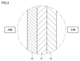
- FIG. 3 is a sectional view showing the bag body (packaging material) in the area surrounded by the two-dot chain line III in FIG. 2.
- FIG. 1 is a diagram schematically showing the first step of the method for manufacturing a pouch.
- FIG. 2 is a diagram schematically showing the second step of the method for manufacturing a pouch. It is a figure which shows typically the 3rd step of the method of manufacturing a pouch. It is a figure which shows typically the modification of the 3rd step of the method of manufacturing a pouch.
- FIG. 1 is a diagram schematically showing the steps of a method for manufacturing a pouch composed of a single sheet;
- FIG. 1 is a table showing the laminated form of the laminate films in Examples 1 to 4 and Comparative Examples 1 to 2, the occurrence of pitch deviation due to heat shrinkage and elongation of the laminate film, and the occurrence of whiskers.
- 15 is a table showing various characteristics of single-layer films A to F used in the examples and comparative examples shown in FIG. 14.
- FIG. 2 is a perspective view showing a modification of the pouch in FIG. 1;
- FIG. 2 is a sectional view showing a bag body and a sealed portion of a spout in the pouch shown in FIG. 1.
- FIG. FIG. 18 is a cross-sectional view showing the bag body and the seal portion of the spout, as seen in the arrow direction on the line XVIII-XVIII in FIG. 17.
- 2 is a table showing the relationship between the lamination form of the laminate films, seal strength, and mechanical suitability in Examples 4 to 6.
- FIG. 1 is a front view showing a pouch in an embodiment of the invention.
- FIG. 2 is a cross-sectional view of the pouch viewed in the direction of the arrows on line II-II in FIG.
- the pouch 100 has a bag body 21.
- the bag body 21 is composed of a plurality of sheets of packaging material.
- the bag body 21 may be composed of a single sheet of packaging material.
- the bag body 21 forms an internal space 38 for accommodating the contents.
- the contents are not particularly limited, and may be liquid or solid such as powder.
- the bag main body 21 has a substantially rectangular shape in plan view.
- the first edge 31 extends in the left-right direction of the bag body 21.
- the second edge 32 and the third edge 33 extend in the vertical direction of the bag body 21 with a space between them.
- the fourth edge 34 extends diagonally across between the first edge 31 and the third edge 33.
- the vertical direction of the bag main body 21 corresponds to the vertical direction when the bag main body 21 is in a posture in which the bottom of the bag main body 21 is placed at the lowest position
- the horizontal direction of the bag main body 21 corresponds to the vertical direction. It corresponds to the direction perpendicular to .
- the vertical and horizontal directions of the bag body 21 are perpendicular to the thickness direction of the first wall portion 22 and the second wall portion 23, which will be described later.
- the bag body 21 has a first wall portion 22, a second wall portion 23, and a gusset portion 24.
- the first wall portion 22 and the second wall portion 23 are arranged to face each other.
- the first wall portion 22 and the second wall portion 23 are overlapped with each other in the thickness direction of the first wall portion 22 and the second wall portion 23.
- the gusset part 24 is inserted between the first wall part 22 and the second wall part 23 which are overlapped with each other.
- the gusset portion 24 is provided at the bottom of the bag body 21.
- the gusset portion 24 is made of a sheet material that is folded back in a mountain fold toward the internal space 38 along a fold line extending in the left-right direction.
- the gusset portion 24 forms a bottom gusset of the bag body 21.
- the lower end portions of the first wall portion 22 and the second wall portion 23 are located inside between the first wall portion 22 and the second wall portion 23.
- the bottom gusset of the bag body 21 may be formed by folding it back.
- a seal portion 26 is provided on the bag body 21.
- the seal portion 26 joins the first wall portion 22, the second wall portion 23, and the gusset portion 24 to each other by thermal welding. More specifically, the seal portion 26 joins the gusset portion 24 and the lower end portions of each of the first wall portion 22 and the second wall portion 23.
- Semicircular notches 27 may be provided on both side edges of the gusset portion 24 in the left-right direction. In this case, the first wall portion 22 and the second wall portion 23 are joined via the notch 27.
- the pouch 100 further includes a spout 41.
- the spout 41 serves as an outlet for taking out the contents from the bag body 21.
- the spout 41 is provided so as to protrude from the fourth edge 34 toward the outside of the bag body 21 .
- the spout 41 has a spout 42 and a cap 43.
- the spout 42 has a cylindrical shape.
- the spout 42 is sandwiched and sealed between the first wall 22 and the second wall 23 at the fourth edge 34, and communicates between the inside and outside of the bag body 21.
- the cap 43 is detachably attached to the spout 42.
- the cap 43 is, for example, a screw cap screwed onto the spout 42.
- the pouch 100 may be a standing pouch that can stand on its own with the gusset portion 24 at the bottom.
- the capacity of the pouch 100 may be 1000 mL or more, or 1200 mL or more.
- the shape of the pouch 100 is not particularly limited, and for example, gores may be provided along the second edge 32 and the third edge 33 in addition to the gusset portion 24.
- FIG. 3 is a sectional view showing the bag body (packaging material) in the area surrounded by the two-dot chain line III in FIG.
- the packaging material constituting the bag body 21 includes a first film 51 and a second film 52.
- the first film 51 is made of biaxial direction oriented polyethylene (BOPE) stretched in the transverse and longitudinal directions.
- BOPE biaxial direction oriented polyethylene
- the second film 52 is laminated on the first film 51.
- the first film 51 and the second film 52 are overlapped with each other in the thickness direction of the first film 51 and the second film 52.
- the second film 52 is disposed further outside the bag body 21 than the first film 51.
- the second film 52 forms the appearance of the bag body 21.
- the second film 52 is bonded to the first film 51 with an adhesive.
- the second film 52 may be joined to the first film 51 by extrusion lamination.
- the heat shrinkage rate of the second film 52 in the lateral direction (heating conditions at 120° C. for 15 minutes) is 10% or less.
- the heat shrinkage rate of the second film 52 is determined, for example, by the following method. First, a second film 52 having a size of 50 mm x 50 mm in the vertical and horizontal directions is prepared as a test piece. The length L 0 of the test piece in the lateral direction before heating is 50 mm. Next, the test piece is placed in a constant temperature bath at 120° C. for 15 minutes. The test piece taken out from the thermostat is left at room temperature for 2 minutes. Next, the length L of the test piece in the lateral direction after heating is measured.
- heat shrinkage rate (%) 100 ⁇ (LL 0 )/L 0 .
- the heat shrinkage rate of the second film 52 being 10% or less means that the absolute value of the value calculated by the above formula is 10% or less.
- the second film 52 may be made of machine direction oriented polyethylene (MDOPE) stretched in the longitudinal direction, or transverse direction oriented polyethylene (TDOPE) stretched in the transverse direction. It may be composed of.
- MDOPE machine direction oriented polyethylene
- TOPE transverse direction oriented polyethylene
- the second film 52 may be made of a resin material other than polyethylene stretched in the longitudinal direction, or may be made of a resin material other than polyethylene stretched in the transverse direction.
- the elastic modulus of the second film 52 in the horizontal direction is 1000 MPa or more, and the elastic modulus of the second film 52 in the longitudinal direction is 1000 MPa or more.
- the elastic modulus of the second film 52 in the horizontal direction is 2000 MPa or less, and the elastic modulus of the second film 52 in the longitudinal direction is 2000 MPa or less.
- the tensile breaking stress of the second film 52 in the longitudinal direction may be 100 MPa or more, or 150 MPa or more.
- the tensile breaking stress of the second film 52 in the transverse direction may be 50 MPa or less.
- the elastic modulus and tensile breaking stress of the second film 52 are determined, for example, by a method according to JIS-K-7161.
- the packaging material constituting the bag body 21 further includes a third film 53.
- the third film 53 is laminated on the first film 51.
- the first film 51 and the third film 53 are overlapped with each other in the thickness direction of the first film 51 and the third film 53.
- the third film 53 is arranged on the opposite side of the second film 52 with respect to the first film 51.
- the third film 53 is arranged inside the bag body 21 more than the first film 51.
- the third film 53 defines the internal space 38 .
- the third film 53 is provided as a sealant layer when forming a sheet-like packaging material into a bag-like shape through a heat welding process.
- the third film 53 is made of heat-sealable resin that can be welded by heating.
- the third film 53 is made of, for example, low density polyethylene, medium density polyethylene, high density polyethylene, or polyolefin resin such as polypropylene.
- the third film 53 is made of linear low density polyethylene (LLDPE).
- the thickness of the first film 51 may be, for example, 10 ⁇ m or more and 50 ⁇ m or less, or 10 ⁇ m or more and 30 ⁇ m or less.
- the thickness of the second film 52 may be, for example, 10 ⁇ m or more and 50 ⁇ m or less, or 10 ⁇ m or more and 30 ⁇ m or less.
- the thickness of the first film 51 may be less than or equal to the thickness of the second film 52, or may be greater than the thickness of the second film 52.
- the thickness of the first film 51 may be the same as the thickness of the second film 52.
- the thickness of the third film 53 may be, for example, 20 ⁇ m or more and 200 ⁇ m or less, or 100 ⁇ m or more and 200 ⁇ m or less.
- the first film 51, the second film 52, and the third film 53 are resin materials of the same type (polyethylene), but different in the form of stretching (uniaxial longitudinal, uniaxial transverse, biaxial, or non-stretched). It may be composed of.
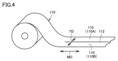
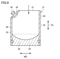
- FIGS. 4 to 10 are diagrams schematically showing steps of a method for manufacturing a pouch.
- a long sheet material 110 is used to manufacture pouch 100.
- the longitudinal direction of the sheet material 110 (flow direction during resin molding of the sheet material 110) is the longitudinal direction, and the lateral direction of the sheet material 110 is the lateral direction.
- the sheet material 110 wound into a roll is pulled out and conveyed in the longitudinal direction.
- the sheet material 110 is provided with longitudinally extending slits 112.
- sheet material 110A and sheet material 110B are obtained.
- sheet material 110A and sheet material 110B are stacked in the thickness direction of these sheets.
- the sheet material 110A and the sheet material 110B correspond to the first wall portion 22 and the second wall portion 23 in the bag body 21, respectively.
- the process is not limited to this, and the sheet material 110 corresponding to the first wall portion 22 and the sheet material 110 corresponding to the second wall portion 23 may be drawn out from separate rolls. In this case, the step of providing slits 112 in sheet material 110 can be omitted.
- a long gusset sheet 124 that will become the basis of the gusset portion 24 is prepared.
- the gusset sheet 124 is provided with a plurality of holes 127, which form the basis of the notches 27, at intervals in the longitudinal direction thereof.
- a gusset sheet 124 is placed along the longitudinally extending edges of sheet material 110A and sheet material 110B while being inserted between sheet material 110A and sheet material 110B.
- a seal portion 126 is provided by heat welding sheet material 110A, sheet material 110B, and gusset sheet 124 to each other.
- the seal portion 126 corresponds to the seal portion 26 on the bag body 21.
- a plurality of bag bodies 21 arranged in the vertical direction are formed.
- a plurality of bag bodies 21 are cut out by cutting the sheet material 110A and the sheet material 110B along the cutting line 131 extending in the transverse direction. As shown in FIG. 7, a plurality of bag bodies 21 may be cut out by cutting sheet material 110A and sheet material 110B along rectangular cutting lines 132.
- the bag body 21 is cut along a cutting line 133 that extends across the first edge 31 and the third edge 33.
- This step is a step of cutting the sheet material 110A and the sheet material 110B shown in FIG. 6 along the cutting line 131, or cutting the sheet material 110A and the sheet material 110B shown in FIG. 7 along the cutting line 132. It may be performed simultaneously with the steps.
- the spout 42 is inserted between the first wall portion 22 and the second wall portion 23 at a position along the cutting line 133 of the previous step and heat welded.
- the contents are injected into the bag body 21 through the opening remaining in the first edge 31.
- the pouch 100 in FIG. 1 is obtained by thermally welding the bag body 21 (first wall 22, second wall 23) along the first edge 31.
- the spout 42 when manufacturing a pouch in which the spout 42 is attached to the center of the first edge 31, the spout 42 is attached to the first wall 22 instead of the steps shown in FIGS. It is inserted between the upper end portion and the upper end portion of the second wall portion 23 and thermally welded. The contents are injected into the bag body 21 through the spout 42.
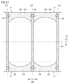
- FIGS. 11 and 12 are diagrams schematically showing the steps of a modification of the method for manufacturing a pouch.
- the steps shown in FIG. 11 correspond to the steps shown in FIG. 5, and the steps shown in FIG. 12 correspond to the steps shown in FIG.
- a plurality of bag bodies 21 arranged in the vertical and horizontal directions are cut out from the sheet material 110.
- two gusset sheets 124 are inserted between sheet material 110A and sheet material 110B, and one edge of sheet material 110A and sheet material 110B extending in the longitudinal direction and the other edge are inserted. be placed along the
- a seal portion 126 is provided by heat-welding the sheet material 110A, the sheet material 110B, and the gusset sheet 124 to each other.
- a plurality of bag bodies 21 arranged in the vertical and horizontal directions are formed.
- a plurality of bag bodies 21 are cut out by cutting the sheet material 110A and the sheet material 110B along the cutting line 133 extending in the horizontal direction and the cutting line 134 extending in the vertical direction.
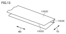
- FIG. 13 is a diagram schematically showing the steps of a method for manufacturing a pouch made of a single sheet. The steps shown in FIG. 13 correspond to the steps shown in FIG.
- a sheet material 110 pulled out from a roll is folded back along a plurality of folds extending in the longitudinal direction. Specifically, the sheet material 110 corresponding to the first wall portion 22 and the sheet material 110 corresponding to the second wall portion 23 are folded so that the sheet material 110 corresponding to the gusset portion 24 is folded. Turn around 110.
- the vertical direction of the pouch 100 corresponds to the lateral direction of the packaging material constituting the pouch 100
- the direction (horizontal direction) orthogonal to the vertical direction of the pouch 100 corresponds to the horizontal direction of the packaging material constituting the pouch 100.
- the first film 51 made of biaxially stretched polyethylene has excellent strength in a well-balanced manner in the longitudinal and transverse directions, while having a high heat shrinkage rate under high temperature conditions.
- the pitch may fluctuate during bag making, the sheet shape may be distorted, or the seal position may shift. can occur.
- the elongated sheet material 110 is wound into a roll at both ends in the longitudinal direction, and therefore, a longitudinal tensile force is applied to the sheet material 110.
- the sheet material 110 is difficult to heat shrink in the longitudinal direction where tensile force is applied, but is easy to heat shrink in the transverse direction where it is not constrained. Therefore, the above-mentioned phenomenon associated with thermal shrinkage tends to become a problem particularly in the lateral direction of the sheet material 110.
- the second film 52 having a heat shrinkage rate (heating condition of 120° C. for 15 minutes) in the lateral direction is 10% or less is laminated on the first film 51.
- Thermal shrinkage of the sheet material 110 in the direction can be effectively suppressed. Therefore, the first film 51, which is made of biaxially oriented polyethylene and has excellent strength in the longitudinal and transverse directions in a well-balanced manner, and the second film 52, which suppresses heat shrinkage in the transverse direction under high-temperature conditions, combine to have a large capacity ( 1000 mL or more), it is possible to realize a pouch 100 that has excellent drop resistance and does not have the bag body 21 rolled up due to heat shrinkage.
- longitudinally uniaxially stretched polyethylene has a characteristic of having a low heat shrinkage rate in the transverse direction. Therefore, in the present embodiment, when the second film 52 is made of longitudinally uniaxially stretched polyethylene, the second film 52 having a heat shrinkage rate (heating condition of 120° C. for 15 minutes) in the transverse direction of 10% or less can be easily manufactured. can be obtained.
- the elastic modulus of the second film 52 in the horizontal direction and the vertical direction is 1000 MPa or more
- the elongation of the packaging material in the horizontal direction and the vertical direction can be suppressed.
- the pitch elongation of the packaging material during bag making can be suppressed, and a higher quality pouch 100 can be manufactured.
- the packaging material is composed only of the same type of resin material (polyethylene), it is easy to recycle and is in line with the sustainable circular economy required by SDGs (Sustainable Development Goals). This can greatly contribute to reducing plastic waste.
- the spout 42 is also preferably made of polyethylene resin.
- FIG. 14 is a table showing the laminated form of the laminate films in Examples 1 to 4 and Comparative Examples 1 to 2, the occurrence of pitch deviation due to heat shrinkage and elongation of the laminate film, and the occurrence of whiskers.
- FIG. 15 is a table showing various characteristics of the single-layer films A to F used in the Examples and Comparative Examples shown in FIG.
- Film A is biaxially oriented polyethylene (BOPE) and has a thickness (actually measured) of 25.0 ⁇ m.
- Film B is made of longitudinally uniaxially stretched polyethylene (MDOPE) and has a thickness (actually measured) of 25.0 ⁇ m.
- Film C is longitudinally uniaxially oriented polyethylene (MDOPE) and has a thickness (actually measured) of 25.0 ⁇ m.
- Film D is made of longitudinally uniaxially stretched polyethylene (MDOPE) and has a thickness (actually measured) of 25.0 ⁇ m.
- Film E is made of transversely uniaxially stretched polyethylene (TDOPE) and has a thickness (actually measured) of 18.0 ⁇ m.
- Film F is biaxially oriented polyethylene (BOPE) and has a thickness (actually measured) of 25.0 ⁇ m.
- the stacking forms of the laminate films used in Examples 1 to 4 and Comparative Examples 1 to 2 are as shown in FIG. ” corresponds to the first film 51, and the film shown in the “inner” item corresponds to the third film 53.
- Example 1 to 4 by using the second film 52 with a heat shrinkage rate in the transverse direction (heating condition of 120° C. for 15 minutes) of 10% or less, pitch deviation occurred only within a controllable range.
- the heat shrinkage rate in the transverse direction was set to 3% or less, thereby reducing pitch deviation. We were able to suppress the outbreak even more effectively.
- each elastic modulus of the second film 52 in the horizontal direction and the vertical direction was 1000 MPa or more, so it was possible to effectively suppress pitch deviation caused by elongation of the laminate film.
- the cut surface of the second film 52 was observed to confirm whether or not whiskers were generated.
- the elastic modulus of the second film 52 in the horizontal and vertical directions was 2000 MPa or less, so no whiskers were generated.
- FIG. ⁇ j'' corresponds to the case where an appearance is observed that is slightly inferior to ⁇ i'' but is acceptable for the product
- ⁇ k'' corresponds to the case where film shrinkage due to shrinkage is observed. (dents) have occurred and it is determined that the appearance is defective.
- FIG. 16 is a perspective view showing a modification of the pouch in FIG. 1.
- the bag body 21 in a pouch 200 according to the present modification, includes a first wall portion 152, a second wall portion 153, a top gusset portion 151, and a bottom gusset portion 154.
- the first wall portion 152 and the second wall portion 153 are arranged to face each other.
- the first wall portion 152 and the second wall portion 153 are overlapped with each other in the thickness direction of the first wall portion 152 and the second wall portion 153.
- the bottom gusset part 154 is provided at the bottom of the bag body 21.
- the bottom gusset portion 154 is connected to the lower end portions of the first wall portion 152 and the second wall portion 153.
- the top gusset portion 151 is provided at the top of the bag body 21.
- the top gusset part 151 is provided facing the bottom gusset part 154 in the vertical direction.
- the top gusset portion 151 is connected to the upper end portions of the first wall portion 152 and the second wall portion 153.
- a spout 42 is provided in the top gusset portion 151.
- the present invention is not limited to the specification of a standing pouch with a bottom gusset, but is applicable to pouches with various shapes.
- FIG. 17 is a sectional view showing the bag body and the sealed portion of the spout in the pouch shown in FIG. 1.
- FIG. 18 is a cross-sectional view showing the bag body and the seal portion of the spout, as seen in the arrow direction on the line XVIII-XVIII in FIG. 17.
- the third film 53 corresponds to the innermost layer disposed innermost among the first film 51, the second film 52, and the third film 53 that constitute the bag body 21. ing.
- the second film 52 corresponds to the outermost layer of the first film 51 , the second film 52 , and the third film 53 that constitute the bag body 21 .
- the spout 42 is inserted between the first wall 22 and the second wall 23 of the bag body 21.
- the spout 42 forms a sealant layer in the bag body 21 and is welded to a third film 53 corresponding to the innermost layer.
- melting point of HDPE 126°C to 137°C
- melting point of nylon 215°C to 225°C
- melting point of PET 264°C
- melting point of LLDPE 105°C to 126°C
- the temperature difference between the melting point of the spout 42 made of HDPE (high-density polyethylene) and the melting point of the outermost layer is small (melting point of MDOPE: typical For example, 130°C).
- the melting point (Ta) of the outermost layer of the bag body 21 is higher than the melting point (Tb) of the innermost layer of the bag body 21 (Ta>Tb).
- the spout 42 is heated by applying an amount of heat corresponding to a temperature higher than the melting point (Tb) of the innermost layer of the bag body 21 and the melting point (Tc) of the spout 42 and lower than the melting point (Ta) of the outermost layer of the bag body 21.
- Tb melting point
- Tc melting point
- Ta melting point
- the spout 42 and the innermost layer of the bag body 21 are preferably made of the same material, polyethylene resin.
- the amount of heat required to melt both the innermost layer of the bag body 21 and the spout 42 exceeds the higher of the melting point (Tc) of the spout 42 and the melting point (Tb) of the innermost layer of the bag body 21. Since there is no set standard, the temperature difference between the temperature during the welding process and the melting point (Ta) of the outermost layer of the bag body 21 can be made larger. Thereby, deformation of the outermost layer of the bag body 21 can be more effectively prevented.
- the melting point (Tc) of the spout 42 may be higher than the melting point (Tb) of the innermost layer of the bag body 21 and lower than the melting point (Ta) of the outermost layer of the bag body 21 (Tb ⁇ Tc). ⁇ Ta).
- the outermost layer of the bag body 21 is preferably MDOPE (longitudinal uniaxially oriented polyethylene) and HDPE (high density polyethylene).
- the melting point (Ta) of the outermost layer of the bag body 21 is preferably 125°C or more and 140°C or less, more preferably 125°C or more and 135°C or less.
- the innermost layer of the bag body 21 is preferably LLDPE (linear low density polyethylene).
- the melting point (Tb) of the innermost layer of the bag body 21 is preferably 100°C or more and 120°C or less, more preferably 105°C or more and 115°C or less.
- the spout 42 is made of polyethylene resin.
- the spout 42 is preferably made of LLDPE (linear low density polyethylene).
- Spout 42 may be LDPE (low density polyethylene).
- the melting point of LDPE (107°C) and the melting point of LLDPE (124°C) are lower than the melting point of HDPE (130°C).
- LLDPE has harder properties than LDEP. Therefore, when LLDPE is used as the material of the spout 42, deformation of the spout 42 is suppressed in the process of welding the spout 42 to the bag body 21.
- the melting point (Tc) of the spout 42 is preferably 100°C or more and 130°C or less, more preferably 105°C or more and 125°C or less.
- Recycled polyethylene may be used as the polyethylene resin forming each layer of the bag body 21.
- the weight of the polyethylene resin is preferably 90% or more of the weight of the entire packaging material, more preferably 95% or more of the weight of the entire packaging material.
- the innermost layer of the bag body 21, which forms the sealant layer, may include a gas barrier resin layer.
- the gas barrier resin layer constituting the heat seal layer may contain at least one type of gas barrier resin.
- gas barrier resins examples include ethylene-vinyl alcohol copolymer (EVOH), polyvinyl alcohol, polyacrylonitrile, nylon 6, nylon 6,6, and polyamides such as polymethaxylylene adipamide (MXD6), polyesters, Examples include polyurethane and (meth)acrylic resin, and among these, EVOH is preferred from the viewpoint of oxygen barrier properties and water vapor barrier properties.
- gas barrier sealant layer having a gas barrier resin layer include polyethylene (LLDPE)/adhesive resin layer (PE)/EVOH/adhesive resin layer (PE)/polyethylene (LLDPE).
- LLDPE low density polyethylene
- FIG. 19 is a table showing the relationship between the stacking form of the laminate films in Examples 4 to 6, seal strength, and mechanical suitability.
- the pouch 100 shown in FIG. 1 was manufactured using the laminate film in the stacked form shown in FIG. 19.
- the pouches 100 in Examples 4 to 6 correspond to the pouch 100 in Example 2 in FIG.
- the film C forming the outermost layer (second film 52) of the bag body 21 is made of MDOPE (melting point: 130° C.)
- the film C forming the innermost layer (third film 53) of the bag body 21 is made of MDOPE (melting point: 130° C.).
- G consists of LLDPE (melting point: 110°C).
- a spout H made of HDPE melting point: 130°C
- Example 5 a spout I made of LLDPE (melting point: 124°C) was used.
- spout J made of LDPE (melting point: 107°C) was used.
- Example 4 in which the melting point of the outermost layer of the bag body 21 and the melting point of the spout 42 are the same, the process of welding the spout 42 to the bag body 21 with an amount of heat that does not cause deformation of the outermost layer of the bag body 21 is carried out. As a result, the amount of heat was insufficient and the seal strength was at its lowest value. On the other hand, in Examples 5 and 6 in which the spout 42 with a low melting point was used, it was possible to melt the spout 42 with an amount of heat that did not cause deformation of the outermost layer of the bag body 21, so high sealing strength was obtained. I was able to do that.
- Example 4 in which high-hardness HDPE and LLDPE were used as materials for the spout 42, no deformation of the spout 42 was observed during the welding process of the spout 42 to the bag body 21.
- Example 6 in which low hardness LDPE was used as the material for the spout 42, slight deformation of the spout 42 was observed.
Landscapes
- Physics & Mathematics (AREA)
- Thermal Sciences (AREA)
- Engineering & Computer Science (AREA)
- Mechanical Engineering (AREA)
- Bag Frames (AREA)
Priority Applications (2)
| Application Number | Priority Date | Filing Date | Title |
|---|---|---|---|
| JP2024539219A JPWO2024029619A1 (https=) | 2022-08-04 | 2023-08-04 | |
| EP23850172.0A EP4552993A1 (en) | 2022-08-04 | 2023-08-04 | Pouch |
Applications Claiming Priority (2)
| Application Number | Priority Date | Filing Date | Title |
|---|---|---|---|
| JP2022-124902 | 2022-08-04 | ||
| JP2022124902 | 2022-08-04 |
Publications (1)
| Publication Number | Publication Date |
|---|---|
| WO2024029619A1 true WO2024029619A1 (ja) | 2024-02-08 |
Family
ID=89849470
Family Applications (1)
| Application Number | Title | Priority Date | Filing Date |
|---|---|---|---|
| PCT/JP2023/028563 Ceased WO2024029619A1 (ja) | 2022-08-04 | 2023-08-04 | パウチ |
Country Status (3)
| Country | Link |
|---|---|
| EP (1) | EP4552993A1 (https=) |
| JP (1) | JPWO2024029619A1 (https=) |
| WO (1) | WO2024029619A1 (https=) |
Citations (5)
| Publication number | Priority date | Publication date | Assignee | Title |
|---|---|---|---|---|
| JP2012246016A (ja) * | 2011-05-27 | 2012-12-13 | Hosokawa Yoko Co Ltd | 粉状物包装用の積層フィルム |
| JP2020055567A (ja) * | 2018-09-28 | 2020-04-09 | 大日本印刷株式会社 | 包装材料およびパウチ |
| JP2020142858A (ja) * | 2019-02-28 | 2020-09-10 | 大日本印刷株式会社 | 包装材料及び包装材料を備えるパウチ |
| JP2020203971A (ja) | 2019-06-14 | 2020-12-24 | 大日本印刷株式会社 | フィルム、該フィルムから構成される包装袋、該フィルムを備える積層体及び該積層体から構成される包装袋 |
| WO2022154053A1 (ja) * | 2021-01-18 | 2022-07-21 | 藤森工業株式会社 | 積層体および包装袋 |
-
2023
- 2023-08-04 JP JP2024539219A patent/JPWO2024029619A1/ja active Pending
- 2023-08-04 WO PCT/JP2023/028563 patent/WO2024029619A1/ja not_active Ceased
- 2023-08-04 EP EP23850172.0A patent/EP4552993A1/en active Pending
Patent Citations (5)
| Publication number | Priority date | Publication date | Assignee | Title |
|---|---|---|---|---|
| JP2012246016A (ja) * | 2011-05-27 | 2012-12-13 | Hosokawa Yoko Co Ltd | 粉状物包装用の積層フィルム |
| JP2020055567A (ja) * | 2018-09-28 | 2020-04-09 | 大日本印刷株式会社 | 包装材料およびパウチ |
| JP2020142858A (ja) * | 2019-02-28 | 2020-09-10 | 大日本印刷株式会社 | 包装材料及び包装材料を備えるパウチ |
| JP2020203971A (ja) | 2019-06-14 | 2020-12-24 | 大日本印刷株式会社 | フィルム、該フィルムから構成される包装袋、該フィルムを備える積層体及び該積層体から構成される包装袋 |
| WO2022154053A1 (ja) * | 2021-01-18 | 2022-07-21 | 藤森工業株式会社 | 積層体および包装袋 |
Also Published As
| Publication number | Publication date |
|---|---|
| JPWO2024029619A1 (https=) | 2024-02-08 |
| EP4552993A1 (en) | 2025-05-14 |
Similar Documents
| Publication | Publication Date | Title |
|---|---|---|
| JPS6344447A (ja) | 熱可塑性樹脂輸送袋 | |
| US12172816B2 (en) | Packaging body | |
| TW524753B (en) | A cross-laminate of oriented films exhibiting improved heat-sealing properties and method of manufacturing such cross-laminate | |
| WO2021049385A1 (ja) | シート材容器 | |
| WO2013031723A1 (ja) | ガゼット袋及び口部材付ガゼット袋、並びにそれらの製造方法 | |
| JP2017217902A (ja) | 積層フィルム | |
| JPH07108550B2 (ja) | 熱可塑性大形袋 | |
| JP7507627B2 (ja) | 包装袋用積層体及び包装袋 | |
| JP5277049B2 (ja) | 収納袋 | |
| JP2009154929A (ja) | 包装袋、その製造装置、および包装袋の製造方法 | |
| WO2024029619A1 (ja) | パウチ | |
| WO2024029618A1 (ja) | パウチ | |
| WO2021241568A1 (ja) | 包装袋 | |
| JP4627038B2 (ja) | 無菌充填用紙容器内縦シールテープ及び縦シールテープ付き無菌充填用紙容器 | |
| JP6988190B2 (ja) | 包装材用フィルム、およびこれを用いた包装材、包装体 | |
| JP7507626B2 (ja) | 包装袋用積層体及び自立袋 | |
| JP4521807B2 (ja) | ヒートシール性複合フィルム | |
| KR20240028767A (ko) | 누액이 방지되고 재활용이 가능한 단일소재를 활용한 파우치팩의 제조방법 및 그를 이용한 파우치팩 | |
| JP4762265B2 (ja) | 重包装袋 | |
| JP7505228B2 (ja) | 積層フィルム | |
| JP4297474B2 (ja) | 多重袋の製造方法 | |
| JP6655437B2 (ja) | パウチ容器用筒状フィルム、パウチ容器用包材及びパウチ容器 | |
| TW202523500A (zh) | 包裝膜用的基材膜 | |
| JP2005178244A (ja) | 医療容器用積層フィルム並びにこの積層フィルムを用いた医療用容器及びその製造方法 | |
| TW202523499A (zh) | 包裝膜用的基材膜 |
Legal Events
| Date | Code | Title | Description |
|---|---|---|---|
| 121 | Ep: the epo has been informed by wipo that ep was designated in this application |
Ref document number: 23850172 Country of ref document: EP Kind code of ref document: A1 |
|
| WWE | Wipo information: entry into national phase |
Ref document number: 2024539219 Country of ref document: JP |
|
| WWE | Wipo information: entry into national phase |
Ref document number: 2501000705 Country of ref document: TH |
|
| WWE | Wipo information: entry into national phase |
Ref document number: 2023850172 Country of ref document: EP |
|
| ENP | Entry into the national phase |
Ref document number: 2023850172 Country of ref document: EP Effective date: 20250210 |
|
| NENP | Non-entry into the national phase |
Ref country code: DE |
|
| WWP | Wipo information: published in national office |
Ref document number: 2023850172 Country of ref document: EP |