WO2024029465A1 - 吊上げ用具、及び吊上げ方法 - Google Patents
吊上げ用具、及び吊上げ方法 Download PDFInfo
- Publication number
- WO2024029465A1 WO2024029465A1 PCT/JP2023/027780 JP2023027780W WO2024029465A1 WO 2024029465 A1 WO2024029465 A1 WO 2024029465A1 JP 2023027780 W JP2023027780 W JP 2023027780W WO 2024029465 A1 WO2024029465 A1 WO 2024029465A1
- Authority
- WO
- WIPO (PCT)
- Prior art keywords
- pair
- lifting
- shroud
- gripping
- pieces
- Prior art date
- Legal status (The legal status is an assumption and is not a legal conclusion. Google has not performed a legal analysis and makes no representation as to the accuracy of the status listed.)
- Ceased
Links
Images



Classifications
-
- F—MECHANICAL ENGINEERING; LIGHTING; HEATING; WEAPONS; BLASTING
- F01—MACHINES OR ENGINES IN GENERAL; ENGINE PLANTS IN GENERAL; STEAM ENGINES
- F01D—NON-POSITIVE DISPLACEMENT MACHINES OR ENGINES, e.g. STEAM TURBINES
- F01D5/00—Blades; Blade-carrying members; Heating, heat-insulating, cooling or antivibration means on the blades or the members
- F01D5/005—Repairing methods or devices
-
- B—PERFORMING OPERATIONS; TRANSPORTING
- B66—HOISTING; LIFTING; HAULING
- B66C—CRANES; LOAD-ENGAGING ELEMENTS OR DEVICES FOR CRANES, CAPSTANS, WINCHES, OR TACKLES
- B66C1/00—Load-engaging elements or devices attached to lifting or lowering gear of cranes or adapted for connection therewith for transmitting lifting forces to articles or groups of articles
- B66C1/10—Load-engaging elements or devices attached to lifting or lowering gear of cranes or adapted for connection therewith for transmitting lifting forces to articles or groups of articles by mechanical means
- B66C1/22—Rigid members, e.g. L-shaped members, with parts engaging the under surface of the loads; Crane hooks
- B66C1/28—Duplicate, e.g. pivoted, members engaging the loads from two sides
- B66C1/30—Duplicate, e.g. pivoted, members engaging the loads from two sides and also arranged to grip the sides of the loads
-
- F—MECHANICAL ENGINEERING; LIGHTING; HEATING; WEAPONS; BLASTING
- F01—MACHINES OR ENGINES IN GENERAL; ENGINE PLANTS IN GENERAL; STEAM ENGINES
- F01D—NON-POSITIVE DISPLACEMENT MACHINES OR ENGINES, e.g. STEAM TURBINES
- F01D25/00—Component parts, details, or accessories, not provided for in, or of interest apart from, other groups
- F01D25/28—Supporting or mounting arrangements, e.g. for turbine casing
-
- F—MECHANICAL ENGINEERING; LIGHTING; HEATING; WEAPONS; BLASTING
- F01—MACHINES OR ENGINES IN GENERAL; ENGINE PLANTS IN GENERAL; STEAM ENGINES
- F01D—NON-POSITIVE DISPLACEMENT MACHINES OR ENGINES, e.g. STEAM TURBINES
- F01D5/00—Blades; Blade-carrying members; Heating, heat-insulating, cooling or antivibration means on the blades or the members
- F01D5/30—Fixing blades to rotors; Blade roots ; Blade spacers
- F01D5/3007—Fixing blades to rotors; Blade roots ; Blade spacers of axial insertion type
-
- F—MECHANICAL ENGINEERING; LIGHTING; HEATING; WEAPONS; BLASTING
- F05—INDEXING SCHEMES RELATING TO ENGINES OR PUMPS IN VARIOUS SUBCLASSES OF CLASSES F01-F04
- F05D—INDEXING SCHEME FOR ASPECTS RELATING TO NON-POSITIVE-DISPLACEMENT MACHINES OR ENGINES, GAS-TURBINES OR JET-PROPULSION PLANTS
- F05D2230/00—Manufacture
- F05D2230/60—Assembly methods
-
- F—MECHANICAL ENGINEERING; LIGHTING; HEATING; WEAPONS; BLASTING
- F05—INDEXING SCHEMES RELATING TO ENGINES OR PUMPS IN VARIOUS SUBCLASSES OF CLASSES F01-F04
- F05D—INDEXING SCHEME FOR ASPECTS RELATING TO NON-POSITIVE-DISPLACEMENT MACHINES OR ENGINES, GAS-TURBINES OR JET-PROPULSION PLANTS
- F05D2230/00—Manufacture
- F05D2230/60—Assembly methods
- F05D2230/68—Assembly methods using auxiliary equipment for lifting or holding
Definitions
- Patent Document 1 discloses a technique in which a lifting jig (lifting tool) is attached to both ends of an arcuate inner shroud, a hook of a lifting device such as a crane is hung on the shackle, and the inner shroud is lifted together with this lifting jig. Disclosed.
- a lifting tool may be used to lift the gas turbine blade in the blade height direction.
- the lifted state of the gas turbine blade by the lifting tool is released, and the load on the gas turbine blade becomes large. Parts may get caught in the groove.
- the entire blade root must be inserted into the groove while adjusting the direction and position of the blade root while the load of the gas turbine blade is applied to the groove, which requires a lot of effort and time to install the gas turbine blade. It may be required. In other words, there is a problem in that it is difficult to smoothly attach the gas turbine blades to the rotor shaft.
- the present disclosure has been made to solve the above problems, and aims to provide a lifting tool and a lifting method that can smoothly attach a gas turbine blade to a rotor shaft.
- a lifting tool for a gas turbine blade having a shroud at the tip, which includes a pair of gripping pieces extending in the vertical direction and rotatably connected to each other. and a gripping part forming a cross-link mechanism in which the lower ends and upper ends of the pair of gripping pieces open and close, respectively, and a pair of lifting parts respectively provided at the lower ends of the pair of gripping pieces, and each
- the lifting portion includes a first member that protrudes from the lower end of the gripping piece in the closing direction of the lower end and has a support surface capable of supporting the lower surface of the shroud from below; and a second member that protrudes in the closing direction with a shorter protrusion length than the first member and has an abutment surface that can abut against a side surface of the shroud.
- a lifting method is a lifting method in which a gas turbine blade having a shroud at its tip is lifted by a lifting tool, and the lifting tool includes a pair of lifting tools extending in the vertical direction and rotatably connected to each other.
- a gripping part that has a gripping piece and forms a cross-link mechanism in which the lower ends of the pair of gripping pieces and the upper ends of the pair of gripping pieces open and close, respectively, and a pair of lifting parts provided at the lower ends of the pair of gripping pieces, respectively.
- each of the lifting parts includes a first member that protrudes from the lower end of the gripping piece in the closing direction of the lower end and has a support surface capable of supporting the lower surface of the shroud from below; and a second member that protrudes in the closing direction with a shorter protrusion length than the first member and has an abutment surface that can come into contact with a side surface of the shroud, and the second member has a second member that protrudes in the closing direction with a shorter protrusion length than the first member, and has a contact surface that can come into contact with a side surface of the shroud, and A blade gripping step in which the side faces facing the upstream side and the side face facing the downstream side are sandwiched, the first member supports the lower surface of the shroud, and the second member is brought into contact with the side surface of the shroud. and a wing lifting step of lifting the lifting tool upward.
- FIG. 2 is a front view (a) and a side view (b) for explaining the configuration of a lifting tool according to an embodiment of the present disclosure, where the side view (b) is viewed from the BB line direction in the front view (a).
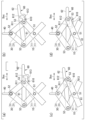
- FIG. 3 is a diagram for explaining how the amount of rotation of a pair of gripping pieces is regulated by the locking mechanism according to the embodiment of the present disclosure.
- 3 is a flowchart illustrating a blade attachment method according to an embodiment of the present disclosure.
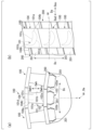
- FIG. 3 is a diagram for explaining a blade attachment process according to an embodiment of the present disclosure.
- FIG. 1 is a diagram for explaining the configuration of a gas turbine blade according to an embodiment of the present disclosure.
- the lifting tool in this embodiment is a tool for lifting a gas turbine blade.
- Lifting tools are used for assembly of gas turbines during turbine manufacture, disassembly and reassembly during turbine maintenance, and the like.
- the gas turbine blade is attached to the rotor shaft of the turbine while maintaining the gas turbine blade in a suspended state using this lifting tool.
- a plurality of gas turbine blades 100 are attached to a disk of a rotor shaft 200 of a turbine (the overall configuration is not shown).
- the rotor shaft 200 has a columnar shape extending in the direction in which the axis Ar extends, and is a rotating shaft rotatable around the axis Ar.
- the plurality of attached gas turbine blades 100 are arranged at equal intervals in the circumferential direction of the rotor shaft 200.
- the direction in which the axis Ar around which the rotor shaft 200 rotates will be referred to as the "axial direction Da”, and the circumferential direction with respect to this axis Ar will simply be referred to as the “circumferential direction Dc", which is perpendicular to the axis Ar.
- This direction is called the "radial direction.”
- one side of both sides in the axial direction Da is referred to as the “axis upstream side Dau”
- the opposite side is referred to as the "axis downstream side Dad”.
- the upstream side Dau of the axis is the side from which the combustion gas generated in the combustor (not shown) of the gas turbine flows
- the downstream side Dad of the axis is the side from which the combustion gas flows away.
- the gas turbine blades 100 are rotor blades arranged in plurality in the circumferential direction Dc by being attached to the rotor shaft 200.
- this gas turbine blade 100 will be referred to as a "moving blade 100.”
- the plurality of rotor blades 100 form a blade row (blade group).
- the rotor blade 100 includes a blade body 101, a platform 102, a shaft attachment portion 103, and a shroud 104.
- the wing body 101 has an airfoil-shaped cross section and extends in a direction perpendicular to this cross section.
- this direction will be referred to as "blade height direction Dwh.”
- the blade height direction Dwh coincides with the radial direction of the rotor shaft 200.
- the side of the rotor shaft 200 with respect to the blade body 101 in the blade height direction Dwh is referred to as the "hub side Dwhs", and the opposite side is referred to as the "tip side Dwht".
- the wing body 101 has a leading edge 101a and a trailing edge 101b, and a ventral side surface 101c and a dorsal side surface 101d that connect the leading edge 101a and the trailing edge 101b and face opposite sides.
- the leading edge 101a becomes the edge of the rotor blade 100 that is closest to the upstream side of the axis Dau.
- the trailing edge 101b becomes the edge Dad of the rotor blade 100 that is furthest downstream of the axis.
- the ventral surface 101c is a concavely curved positive pressure surface.
- the dorsal surface 101d is a negative pressure surface that curves convexly toward the side where the ventral surface 101c is concave, and faces the opposite side to the ventral surface 101c.
- Platform 102 is a pedestal that supports wing body 101.
- the platform 102 is provided at the end of the hub-side Dwhs of the wing body 101.
- the platform 102 is a plate-shaped member that extends from the end of the hub side Dwhs of the blade body 101 in a direction having a component perpendicular to the blade height direction Dwh. Note that this platform 102 is formed with a gas path surface 102a that faces the chip side Dwht and comes into contact with combustion gas.
- the shaft attachment part 103 fixes the platform 102 to the rotor shaft 200.
- the shaft attachment part 103 has a shank 103a extending from the platform 102 in the blade height direction Dwh to the side opposite to the blade body 101, and a blade root 103b extending from the shank 103a to the side opposite to the blade body 101 in the blade height direction Dwh. have.
- the cross-sectional shape of the blade root 103b has a Christmas tree shape. This blade root 103b can fit into a blade root groove 201 formed in the rotor shaft 200.
- the shroud 104 is provided at the end of the wing body 101 on the tip side Dwht. Therefore, a shroud 104 is provided at the tip (tip side Dwht) of the gas turbine blade 100.
- the shroud 104 extends from the wing body 101 in a direction perpendicular to the radial direction. When the rotor blades 100 are attached to the rotor shaft 200 to form a blade row, each shroud 104 comes into contact with an adjacent shroud 104 in the circumferential direction Dc, thereby increasing the rigidity of the entire blade row.
- the shroud 104 has a side surface 104b that faces Dau on the upstream side of the axis and a side surface 104b that faces Dad on the downstream side of the axis when the rotor blade 100 is attached to the rotor shaft 200. Further, the shroud 104 has a lower surface 104a facing the hub side Dwhs.
- the lifting tool 1 in this embodiment includes a gripping part 10, a lifting part 20, a V-shaped link mechanism 30, an external force applying part 40, a locking mechanism 60, a handle part 70, and a third part. It includes a first connecting pin 51, a second connecting pin 52, and a third connecting pin 53.
- the grip portion 10 constitutes the main body portion of the lifting tool 1, and is a portion that generates a force for gripping (restraining) the rotor blade 100.
- the grip part 10 has a pair of grip pieces 11.
- the pair of gripping pieces 11 extend in the vertical direction Dv (vertical direction in FIG. 1).
- the vertical direction Dv in this embodiment corresponds to the vertical direction.
- the upper side in the vertical direction Dv will be simply referred to as the "upper side Dvu”
- the lower side in the vertical direction Dv will simply be referred to as the "lower side Dvd”.
- the pair of gripping pieces 11 in this embodiment are made of, for example, a material such as metal.
- the pair of gripping pieces 11 overlap each other and are rotatably connected to each other by a first connecting pin 51.
- the pair of gripping pieces 11 constitute a cross-link mechanism in which the lower ends 11b and the upper ends 11a open and close, respectively, by mutually rotating about the first connecting pin 51.
- the pair of gripping pieces 11 can rotate in opposite directions.
- the rotation in the direction in which the upper ends 11a and the lower ends 11b approach each other is referred to as "closing", and the upper ends 11a and the lower ends
- the direction in which the parts 11b are separated from each other is called "opening".
- the direction in which the upper ends 11a and the lower ends 11b of the pair of gripping pieces 11 move away from and approach each other is referred to as the "opening/closing direction Doc.”
- the direction in which the upper ends 11a and the lower ends 11b of the pair of grip pieces 11 approach each other is referred to as the "closing direction”
- the upper ends 11a and the lower ends is referred to as the "opening direction.”
- the closing direction refers to the side surface 104b of the shroud 104 of the rotor blade 100 that faces Dau on the upstream side of the axis when the rotor blade 100 is attached to the rotor shaft 200, and the side face 104b that faces Dad on the downstream side of the axis when the rotor blade 100 is attached to the rotor shaft 200.
- the direction is to sandwich the side surface 104b. More preferably, the closing direction is made to coincide with the axial direction Da when the rotor blade 100 is attached to the rotor shaft 200.
- the lifting portion 20 is a portion that supports the rotor blade 100 while interlocking with the gripping portion 10, and also holds and restrains the rotor blade 100.
- the lifting parts 20 are provided at the lower ends 11b of the pair of grip parts 10, respectively.
- the lifting section 20 includes a substrate 23, a first member 21, and a second member 22.
- the substrate 23 is a member having a flat plate shape.
- the substrate 23 is fixed to the lower end 11b of the grip portion 10 by a fastening member (not shown) such as a bolt.
- the substrate 23 is made of a material such as metal.
- the substrates 23 fixed to the respective lower ends 11b of the pair of gripping parts 10 have opposing surfaces 23a facing each other.
- the pair of opposing surfaces 23a are arranged between the side surface 104b of the shroud 104 that faces Dau on the upstream side of the axis and the side surface 104b that faces Dad on the downstream side of the axis. Sandwich.
- the pair of substrates 23 come close to each other when the pair of gripping pieces 11 are closed in the closing direction. Further, the pair of substrates 23 are separated from each other when the pair of grip pieces 11 are opened in the opening direction. That is, the opposing surfaces 23a of the pair of substrates 23 move away from each other and move closer to each other as the pair of gripping pieces 11 open and close.
- the first member 21 is provided on the opposing surface 23a of the substrate 23.
- the first member 21 is a member that protrudes from the facing surface 23a of each substrate 23 in the closing direction of the lower end 11b. That is, the first member 21 is provided on the substrate 23 so as to protrude from the opposing surface 23a in a direction in which they approach each other.
- a plurality of first members 21 in this embodiment are arranged on the opposing surface 23a.
- the first member 21 is made of synthetic resin material.
- MC nylon registered trademark
- the like can be used as the material forming the first member 21 in this embodiment.
- the first member 21 has a planar support surface 21a that faces upward Dvu when the pair of gripping pieces 11 are closed in the closing direction.
- the support surface 21a of the first member 21 faces the lower surface 104a of the shroud 104 in the vertical direction Dv when the pair of opposing surfaces 23a sandwich the shroud 104 between them, and supports this lower surface 104a from the lower side Dvd. I can do it.
- the second member 22 is provided on the opposing surface 23a of the substrate 23.
- the second member 22 is arranged above the first member 21 Dvu.
- a plurality of second members 22 in this embodiment are arranged on the opposing surface 23a.
- the second member 22 is a member that protrudes from the facing surface 23a of each substrate 23 in the closing direction of the lower end 11b.
- the second member 22 protrudes in the closing direction with a shorter protrusion length than the first member 21.
- the "protrusion length” here means the protrusion length from the substrate 23 in the closing direction.
- the second member 22 is made of synthetic resin material.
- MC nylon registered trademark
- the like can be used as the material forming the second member 22 in this embodiment.
- the second member 22 has a contact surface 22a that can come into contact with the side surface 104b of the shroud 104 when the pair of gripping pieces 11 are closed in the closing direction.
- the abutting surface 22a has a convex curved shape that is convex toward the closing direction from the opposing surface 23a of the substrate 23.
- the support surface 21a of the first member 21 supports the lower surface 104a of the shroud 104 from the lower side Dvd
- the contact surface 22a of the second member 22 supports the lower surface 104a of the shroud 104.
- the lifting portion 20 restrains the rotor blade 100 by coming into contact with the side surface 104b of the rotor blade 100 . That is, by the gripping part 10 and the lifting part 20 working together, the rotor blade 100 can be lifted while being gripped.
- the V-shaped link mechanism 30 is a link mechanism for opening and closing the grip portion 10.
- the V-shaped link mechanism 30 interlocks with the grip portion 10.
- the V-shaped link mechanism 30 has a pair of link pieces 31.
- the pair of link pieces 31 extend in the vertical direction Dv.
- the pair of link pieces 31 overlap each other, and their upper ends 31a are rotatably connected to each other by a second connecting pin 52.
- the lower end 31b of each of the pair of link pieces 31 is rotatably connected to the upper end 11a of the corresponding grip piece 11 by a third connecting pin 53.
- the link piece 31 in this embodiment is made of a material such as metal, for example.
- the lower ends 31b of the pair of link pieces 31 are close to each other when the grip pieces 11 are closed based on these connecting parts, and are spaced apart from each other when the grip pieces 11 are opened using these connecting parts as a base point. do.
- the external force applying part 40 is connected to a second connecting pin 52 that connects the link pieces 31 to each other, and is a connecting metal fitting to which a crane wire (not shown) is hung and lifted to the upper side Dvu by this wire. .
- the external force applying part 40 can lift the rotor blade 100 to the upper side Dvu through the V-shaped link mechanism 30, the gripping part 10, and the lifting part 20.
- the external force applying unit 40 can lift the rotor blade 100 by applying an external force from outside the lifting tool 1 toward the upper side Dvu.
- the locking mechanism 60 is a member that can restrict the amount of rotation of the pair of gripping pieces 11 in the closing direction and opening direction.
- the locking mechanism 60 is provided so as to span the upper ends 11a of the pair of gripping pieces 11.
- the lock mechanism 60 is made of a material such as metal, for example.
- the lock mechanism 60 in this embodiment includes a lock plate 61 and a lever portion 62.
- the lock plate 61 is provided across the pair of third connecting pins 53.
- the lock plate 61 is rotatably provided on one of the pair of third connecting pins 53 .
- a guide hole 610 that can guide the other third connecting pin 53 is formed in a portion of the lock plate 61 opposite to the portion provided on one third connecting pin 53.
- the other third connecting pin 53 is arranged inside this guide hole 610.
- the guide hole 610 in this embodiment includes a first accommodation hole 611 and a second accommodation hole 612 which are spaced apart from each other and can accommodate the other third connecting pin 53 in a received state; It is constituted by a connection hole 613 that connects the first accommodation hole 611 and the second accommodation hole 612.
- the first accommodation hole 611 and the second accommodation hole 612 are arranged on the upper side Dvu than the connection hole 613.
- the connection hole 613 extends in one direction across the first accommodation hole 611 and the second accommodation hole 612 on the lower side Dvd.
- the guide hole 610 consisting of the first accommodation hole 611, the second accommodation hole 612, and the connection hole 613 has a U-shape when viewed from the front.
- One direction in this embodiment corresponds to the opening/closing direction Doc of the pair of gripping pieces 11.
- the lever portion 62 is provided on the lock plate 61 in an integral state with the lock plate 61, and is a portion that is operated by the hands of the operator who uses the lifting tool 1.
- the lever portion 62 in this embodiment extends in one direction from the end of the lock plate 61 on the side of the other third connecting pin 53 of one third connecting pin 53 and the other third connecting pin 53.
- the other third connecting pin 53 When the other third connecting pin 53 is located in the first accommodation hole 611 in the guide hole 610 (upper left (a) in FIG. 2), when the lever part 62 is pushed up to the upper side Dvu, the other third connecting pin 53 The three connecting pins 53 are arranged at the end of the connection hole 613 on the closing direction side (upper right (b) in FIG. 2). Next, as the pair of gripping pieces 11 rotate in the opening direction, the other third connecting pin 53 is guided in one direction (opening direction) by the connection hole 613 (lower left (c) in FIG. 2). Next, when the lever part 62 is pushed down, the other third connecting pin 53 is placed in the second accommodation hole 612 (lower right (d) in FIG. 2).
- the guide hole 610 rotates (opens and closes) the pair of grip pieces 11 by the length of the connection hole 613, and is received by the second accommodation hole 612, so that the pair of grip pieces 11 Further rotation in the opening direction can be stopped.
- the guide hole 610 rotates (opens and closes) the pair of grip pieces 11 by the length of the connection hole 613, and is received by the first accommodation hole 611, thereby allowing the pair of grip pieces 11 to rotate (open and close) by the length of the connection hole 613. Further rotation in the closing direction can be stopped.
- the state of the locking mechanism 60 when the other third connecting pin 53 is placed in the first accommodation hole 611 will be referred to as a "closed state", and the other third connecting pin 53 will be referred to as the "closed state”.
- the state of the locking mechanism 60 when placed within the hole 612 is referred to as the "open state.”
- the handle portion 70 is provided on one of the pair of gripping pieces 11, and is operated by the hand of an operator using the lifting tool 1, so that the handle portion 70 can hold the entire lifting tool 1. This is a part that can be moved.
- the handle portion 70 is pushed up or down in the vertical direction Dv by the operator's hand, so that the pair of gripping pieces 11 Rotation in the opening/closing direction Doc is adjustable.
- the handle portion 70 is arranged on the lower side Dvd of the first connecting pin 51 to which the pair of gripping pieces 11 are connected.
- the handle portion 70 in this embodiment includes an upper horizontal bar 71, a lower horizontal bar 72, and a vertical bar 73.
- the upper horizontal bar 71 extends in one direction (opening direction), which is the direction in which the lever portion 62 extends from the gripping piece 11 .
- the lower horizontal bar 72 is arranged on the lower side DVD than the upper horizontal bar 71.
- the lower horizontal bar 72 extends from the grip piece 11 in the one direction.
- the vertical bar 73 is a part held by the operator's hand, and connects the upper horizontal bar 71 and the lower horizontal bar 72 in the vertical direction Dv.
- the blade attachment method in this embodiment will be explained with reference to FIG. 3.
- a blade gripping process S1, a blade lifting process S2, and a blade attachment process S3 are performed.
- the method for lifting the rotor blade 100 is realized by performing the blade gripping process S1 and the blade lifting process S2.
- the blade gripping step S1 is a step of causing the lifting tool 1 to grip the rotor blade 100.
- the lock mechanism 60 is opened.
- the closing direction of the pair of gripping pieces 11 in the lifting tool 1 is determined from the side surface 104b of the shroud 104 that faces Dau on the upstream side of the axis when the rotor blade 100 is attached to the rotor shaft 200, and the side surface 104b on the downstream side of the axis. The direction is such that the side face 104b facing Dad is sandwiched therebetween.
- the operator moves the entire lifting tool 1 by handling the handle portion 70. Note that the rotor blade 100 itself may be moved toward the lifting tool 1.
- the entire lifting tool 1 is moved so that the shroud 104 of the rotor blade 100 is sandwiched between the pair of lifting parts 20.
- the locking mechanism 60 is brought into the closed state by pushing up the lever part 62 to the upper side Dvu, rotating the pair of gripping pieces 11 in the closing direction, and pushing down the lever part 62 to the lower side Dvd.
- the support surface 21a of the first member 21 supports the lower surface 104a of the shroud 104
- the contact surface 22a of the second member 22 contacts the side surface 104b of the shroud 104.
- the blade lifting process S2 is a process executed after the blade gripping process S1, and lifts the rotor blade 100 to the upper side Dvu.
- an external force directed toward the upper side Dvu is applied to the external force applying section 40, thereby lifting the rotor blade 100 to the upper side Dvu.
- a crane wire or the like is applied to the external force applying part 40, and the external force applying part 40 is lifted to the upper side Dvu by this wire, so that the rotor blade 100 is lifted to the upper side Dvu together with the lifting tool 1. .
- the blade attachment process S3 is a process executed after the blade lifting process S2, and the rotor blade 100 is attached to the rotor shaft 200 of the turbine. Specifically, as shown in FIG. 4, with the rotor blade 100 lifted by the lifting tool 1, the blade root 103b of the shaft attachment portion 103 of the rotor blade 100 is inserted into the blade root groove 201 formed in the rotor shaft 200. Insert from the axial direction Da.
- the blade root 103b can be inserted into the blade root groove 201 with the lifting tool 1 in a state where the rotor blade 100 is lifted, that is, with the blade root 103b floating above the inner surface of the blade root groove 201. In this embodiment, it is inserted along the direction in which the blade root groove 201 extends from Dau on the upstream side of the axis. After the insertion of the blade root 103b into the blade root groove 201 is completed, the lifting tool 1 is removed from the rotor blade 100.
- the rotor blade 100 is lifted by the lifting tool 1, and the rotor blade 100 is attached to the rotor shaft 200.
- the protrusion length of the second member 22 is shorter than the protrusion length of the first member 21, for example, by rotating the grip portion 10 so as to open it in a direction opposite to the closing direction, the shroud of the rotor blade 100 can be closed. 104 can be supported only by the first member 21. Thereby, the position, orientation, etc. of the rotor blade 100 can be adjusted more finely while maintaining the state in which the rotor blade 100 is supported by the first member 21.
- each upper end 11a of the pair of grip pieces 11 of the grip part 10 is connected to each lower end 31b of the pair of link pieces 31 of the V-shaped link mechanism 30, and the pair of link pieces 31 are connected to each other.
- An external force applying section 40 is connected to the upper end 31a.
- the rotor blade 100 when the rotor blade 100 is lifted, the upper ends 31a of the pair of link pieces 31 connected to the external force applying part 40 can be tightened. Therefore, the rotor blade 100 can be more firmly sandwiched between the second members 22 of the pair of lifting parts 20.
- the opening/closing direction Doc and the axial direction Da of the lower ends 11b of the gripping pieces 11 of the pair of gripping parts 10 are aligned. Therefore, for example, when attaching the rotor blade 100 to the rotor shaft 200, it is possible to prevent the lifting tool 1 from interfering with the adjacent rotor blade 100 that has already been attached to the rotor shaft 200. Therefore, the rotor blade 100 can be attached to the rotor shaft 200 more smoothly.
- the amount of rotation of the pair of grip pieces 11 is regulated by the lock mechanism 60, the movement of the lifting part 20 in the vertical direction Dv due to the rotation of the pair of grip pieces 11 is regulated. I can do it. Therefore, when attaching the rotor blade 100 to the rotor shaft 200, it is possible to further suppress the application of load from the rotor blade 100 to the blade root groove 201. Furthermore, by restricting the amount of rotation of the pair of gripping pieces 11, the movement of the lifting portion 20 in the closing direction is restricted, so that excessive pinching force is not applied to the shroud 104 by the pair of second members 22. Can be suppressed.
- the rotation of the pair of gripping pieces 11 can be adjusted by pushing up or pushing down the handle portion 70 in the vertical direction Dv, so the position of the moving blade 100 in the vertical direction Dv can be adjusted with high precision. can do.
- the first member 21 and the second member 22 of the lifting part 20 are formed of a synthetic resin material. For this reason, for example, when the lifting tool 1 lifts the rotor blade 100, the supporting surface of the first member 21 is Damage to the shroud 104 from the contact surface 22a of the second member 21a and the second member 22 can be suppressed.
- the facing surface 23a of the substrate 23 of the lifting part 20 provided at each of the lower ends 11b of the pair of gripping pieces 11 is connected to the side surface 104b facing the axis upstream side Dau among the side surfaces 104b of the shroud 104, and the side surface 104b facing the axis line upstream side Dau,
- the side surface 104b facing the downstream side Dad extends parallel to the direction in which it spreads.
- the support surface 21a of the first member 21 supports the shroud 104 in a well-balanced manner, and the contact surface 22a of the second member 22 contacts an appropriate location on the side surface 104b of the shroud 104. can be done.
- handle portion 70 described in the above embodiment may be provided on both of the pair of grip pieces 11.
- the contact surface 22a of the second member 22 described in the above embodiment may have a spherical shape, for example.
- first member 21 and the second member 22 are formed of a synthetic resin material
- the present invention is not limited thereto.
- the parts surface layer Only a portion of the first member 21 and a portion of the second member 22 may be formed of a synthetic resin material.
- gas turbine blade 100 and lifting tool 1 described in the above embodiment can be used as a set. That is, the gas turbine blade 100 and the lifting tool 1 may be implemented as a set.
- the lifting tool 1 is a lifting tool 1 for a gas turbine blade 100, which is provided with a shroud 104 at its tip, and includes a pair of lifting tools 1 extending in the vertical direction Dv and rotatably connected to each other.
- a gripping part 10 having a gripping piece 11 and forming a cross-link mechanism in which the lower ends 11b and upper ends 11a of the pair of gripping pieces 11 open and close, respectively, and a pair of gripping pieces 11 provided at the lower ends 11b of the pair of gripping pieces 11, respectively.
- Each lifting part 20 projects from the lower end 11b of the gripping piece 11 in the closing direction of the lower end 11b, and has a supporting surface 21a capable of supporting the lower surface 104a of the shroud 104 from below.
- a first member 21 having a first member 21; and a second member 22 having a contact surface 22a.
- the lower surface 104a of the shroud 104 of the moving blade 100 is supported from below by the support surface 21a of the first member 21 of each lifting part 20, and each lifting part 20
- the side surface 104b of the shroud 104 of the rotor blade 100 is sandwiched between the contact surface 22a of the second member 22. That is, the rotor blade 100 is supported by the first member 21 and restrained by the second member 22. Therefore, since the rotor blade 100 hangs more stably, for example, when the gas turbine blade 100 is inserted into the groove of the rotor shaft 200, the entire load of the gas turbine blade 100 is not borne by the groove.
- the lifting tool 1 according to the second aspect is the lifting tool 1 of (1), in which the upper ends 31a are rotatably connected to each other, and the lower ends 31b are connected to the corresponding gripping piece.
- the V-shaped link mechanism 30 consisting of a pair of link pieces 31 rotatably connected to the upper end 11a of the V-shaped link mechanism 30, and an external force applying part 40 provided at the upper end 31a of the V-shaped link mechanism 30 may be further provided. good.
- the lifting tool 1 according to the third aspect is the lifting tool 1 of (1) or (2), in which the closing direction is the side surface 104b facing upstream among the side surfaces 104b of the shroud 104. It may be in the sandwiching direction.
- the lifting tool 1 according to the fourth aspect is the lifting tool 1 of (2), and is provided so as to span the upper ends 11a of the pair of gripping pieces 11, and is provided so as to extend between the upper ends 11a of the pair of gripping pieces 11. It may further include a locking mechanism 60 capable of regulating the amount of rotation in the closing direction and in the opening direction opposite to the closing direction.
- the lifting tool 1 according to the fifth aspect is the lifting tool 1 according to (4), in which the upper ends 11a of the pair of gripping pieces 11 and the lower ends 31b of the pair of link pieces 31 are connected.
- the locking mechanism 60 is a lock in which one of the pair of connecting pins is rotatably provided and a guide hole 610 is formed to guide the other connecting pin. It has a plate 61 and a lever part 62 extending from the other connecting pin side of the locking plate 61, and the guide holes 610 are spaced apart from each other and accommodated in a state where the other connecting pin is received.
- the lever part 62 With the first accommodating hole 611 and the second accommodating hole 612 and the other connecting pin located in the first accommodating hole 611 or the second accommodating hole 612, the lever part 62 is moved upward.
- the other connecting pin is moved from the first accommodation hole 611 to the second accommodation hole 612 or the It may also include a connecting hole 613 that can be guided from the second housing hole 612 to the first housing hole 611 .
- the lock mechanism 60 can be realized with a more specific configuration.
- the lifting tool 1 according to the sixth aspect is the lifting tool 1 according to any one of (1) to (5), and is located on the lower side DVD than the part where the pair of gripping pieces 11 are connected to each other. It may further include a handle part 70 that is provided and can adjust the rotation of the pair of gripping pieces 11 by being pushed up or down in the vertical direction Dv.
- the lifting tool 1 according to the seventh aspect is any one of (1) to (6), in which the first member 21 and the second member 22 are formed of a synthetic resin material. may have been done.
- the lifting method according to the eighth aspect is a lifting method in which a gas turbine blade 100 having a shroud 104 provided at its tip is lifted by a lifting tool 1, wherein the lifting tool 1 extends in the vertical direction Dv and A gripping portion 10 having a pair of gripping pieces 11 rotatably connected to each other and forming a cross-link mechanism in which lower ends 11b and upper ends 11a of the pair of gripping pieces 11 open and close, respectively; a pair of lifting parts 20 provided at the lower ends 11b of the shroud 104, each lifting part 20 protruding from the lower end 11b of the gripping piece 11 in the closing direction of the lower end 11b, and the lower surface 104a of the shroud 104.
- a first member 21 having a support surface 21a capable of supporting the shroud from below; and a first member 21 that protrudes in the closing direction above the first member 21 and with a shorter protrusion length than the first member 21; a second member 22 having a contact surface 22a that can come into contact with the side surface 104b of the shroud 104, and the closing direction is the side surface 104b facing the upstream side and the side surface facing the downstream side among the side surfaces 104b of the shroud 104.
- the first member 21 supports the lower surface 104a of the shroud 104, and the second member 22 is brought into contact with the side surface 104b of the shroud 104.
- a blade lifting step S2 of lifting the wing to the side Dvu is executed.
Landscapes
- Engineering & Computer Science (AREA)
- Mechanical Engineering (AREA)
- General Engineering & Computer Science (AREA)
- Load-Engaging Elements For Cranes (AREA)
Abstract
Description
本願は、2022年8月5日に日本に出願された特願2022-125213号に対して優先権を主張し、その内容をここに援用する。
本実施形態における吊上げ用具は、ガスタービン翼を吊上げるための用具である。吊上げ用具は、ガスタービンにおけるタービン製造時の組付けや、タービンのメンテナンス時の分解・再組立て等で使用される。タービンの製造時における組付けでは、この吊上げ用具を用いてガスタービン翼が吊り上がった状態を維持しつつ、このガスタービン翼をタービンのロータ軸に取り付ける。
図5に示すように、ガスタービン翼100は、複数がタービン(全体構成の図示は省略)のロータ軸200のディスクに取り付けられる。ロータ軸200は、軸線Arの延びる方向に延びる柱状を成すとともに、軸線Ar回りに回転可能な回転軸である。取り付けられた複数のガスタービン翼100は、ロータ軸200の周方向に等間隔に配置される。
ガスタービン翼100は、ロータ軸200に取り付けることで周方向Dcに複数配列される動翼である。以下、説明の便宜上、このガスタービン翼100を「動翼100」と称する。ロータ軸200上で動翼100が周方向Dcに複数配列されることで、これら複数の動翼100は、翼列(翼群)を成している。
動翼100は、翼体101と、プラットフォーム102と、軸取付部103と、シュラウド104とを有している。
翼体101は、断面が翼型を成し、この断面に対して垂直な方向に延びている。以下、説明の便宜上、この方向を「翼高さ方向Dwh」と称する。動翼100がロータ軸200に固定された状態では、翼高さ方向Dwhは、ロータ軸200の径方向に一致する。ここで、翼高さ方向Dwhで翼体101に対してロータ軸200の側を「ハブ側Dwhs」と称し、その反対側を「チップ側Dwht」と称する。
プラットフォーム102は、翼体101を支持する台座である。プラットフォーム102は、翼体101におけるハブ側Dwhsの端部に設けられている。プラットフォーム102は、翼体101のハブ側Dwhsの端部から翼高さ方向Dwhに対して垂直な成分を有する方向に広がる板状の部材である。なお、このプラットフォーム102には、チップ側Dwhtを向くとともに、燃焼ガスと接触するガスパス面102aが形成されている。
軸取付部103は、プラットフォーム102をロータ軸200に固定する。軸取付部103は、プラットフォーム102から翼高さ方向Dwhで翼体101と反対側に延びるシャンク103aと、シャンク103aから翼高さ方向Dwhで翼体101とは反対側に延びる翼根103bとを有している。翼根103bの断面形状は、クリスマスツリー形状を成している。この翼根103bは、ロータ軸200に形成された翼根溝201に嵌り込むことができる。
シュラウド104は、翼体101におけるチップ側Dwhtの端部に設けられている。したがって、ガスタービン翼100の先端(チップ側Dwht)には、シュラウド104が設けられている。シュラウド104は、径方向に対して垂直な方向に翼体101から広がっている。各シュラウド104は、動翼100がロータ軸200に取り付けられて翼列を成した際、周方向Dcに隣り合うシュラウド104に当接することで翼列全体の剛性を高めている。シュラウド104は、動翼100がロータ軸200に取り付けられた際、軸線上流側Dauを向く側面104b、及び軸線下流側Dadを向く側面104bを有している。また、シュラウド104は、ハブ側Dwhsを向く下面104aを有している。
図1に示すように、本実施形態における吊上げ用具1は、把持部10と、吊上げ部20と、V字リンク機構30と、外力付与部40と、ロック機構60と、取っ手部70と、第一連結ピン51と、第二連結ピン52と、第三連結ピン53とを備えている。
把持部10は、吊上げ用具1における本体部分を成しており、動翼100を把持(拘束)するための力を生み出す部分である。
把持部10は、一対の把持片11を有している。
一対の把持片11は、上下方向Dv(図1における上下方向)に延びている。本実施形態における上下方向Dvは、鉛直方向に一致する。以下、上下方向Dvにおける上方側を単に「上方側Dvu」と称し、上下方向Dvにおける下方側を単に「下方側Dvd」と称する。本実施形態における一対の把持片11は、例えば金属等の材料で形成されている。
吊上げ部20は、把持部10と連動した状態で、動翼100を支持するとともに挟み込んで拘束する部分である。吊上げ部20は、一対の把持部10における下端11bにそれぞれ設けられている。
吊上げ部20は、基板23と、第一部材21と、第二部材22とを有している。
基板23は、平板状を成している部材である。基板23は、ボルト等の締結部材(図示省略)によって把持部10における下端11bに固定されている。基板23は、例えば金属等の材料で形成されている。一対の把持部10のそれぞれの下端11bに固定された基板23同士は、互いに対向する対向面23aを有している。
第一部材21は、基板23の対向面23aに設けられている。第一部材21は、各基板23の対向面23aから下端11bの閉方向に突出している部材である。すなわち、第一部材21は、対向面23aから互いに近接する方向に突出するように基板23に設けられている。
第二部材22は、基板23の対向面23aに設けられている。第二部材22は、第一部材21よりも上方側Dvuに配置されている。また、本実施形態における第二部材22は、対向面23a上に複数配置されている。第二部材22は、各基板23の対向面23aから下端11bの閉方向に突出している部材である。
V字リンク機構30は、把持部10を開閉させるためのリンク機構である。V字リンク機構30は、把持部10と連動する。
V字リンク機構30は、一対のリンク片31を有している。
一対のリンク片31は、上下方向Dvに延びている。一対のリンク片31は、互いに重なり合うとともに、上端31a同士が第二連結ピン52によって互いに回動可能に連結されている。一対のリンク片31のそれぞれの下端31bは、第三連結ピン53によって、対応する把持片11の上端11aに回動可能に連結されている。本実施形態におけるリンク片31は、例えば金属等の材料で形成されている。
外力付与部40は、リンク片31同士を連結する第二連結ピン52に連結されており、クレーンのワイヤ(図示省略)等がかけられるとともに、このワイヤによって上方側Dvuに吊上げられる結合金具である。
ロック機構60は、一対の把持片11の閉方向及び開方向への回動量を規制することができる部材である。ロック機構60は、一対の把持片11の上端11a同士に亘るように設けられている。ロック機構60は、例えば金属等の材料で形成されている。
本実施形態におけるロック機構60は、ロック板61と、レバー部62とを有している。
ロック板61は、一対の第三連結ピン53に亘って設けられている。ロック板61は、一対の第三連結ピン53のうち、一方の第三連結ピン53に回動可能に設けられている。また、ロック板61における一方の第三連結ピン53に設けられる部分と反対側の部分には、他方の第三連結ピン53を案内することができる案内孔610が形成されている。他方の第三連結ピン53は、この案内孔610の内側に配置されている。
レバー部62は、ロック板61と一体の状態でロック板61に設けられており、吊上げ用具1を利用する作業者の手によって操作される部分である。本実施形態におけるレバー部62は、ロック板61における一方の第三連結ピン53と他方の第三連結ピン53とのうち他方の第三連結ピン53側の端部から一方向に延びている。
図1に示すように、取っ手部70は、一対の把持片11のうち一方の把持片11に設けられ、吊上げ用具1を利用する作業者の手によって操作されることで、吊上げ用具1全体を移動させることができる部分である。
上部横棒71は、把持片11からレバー部62が延びる方向である一方向(開方向)に延びている。下部横棒72は、上部横棒71よりも下方側Dvdに配置されている。下部横棒72は、把持片11から上記一方向に延びている。縦棒73は、作業者の手によって把持される部分であり、上部横棒71及び下部横棒72を上下方向Dvに接続している。
続いて、本実施形態における翼取付方法について、図3を参照して説明する。当該翼取付方法では、翼把持工程S1と、翼吊上げ工程S2と、翼取付工程S3とを実行する。 また、本実施形態では、これら翼把持工程S1と翼吊上げ工程S2とが実行されることによって、動翼100の吊上げ方法が実現する。
翼把持工程S1は、吊上げ用具1に動翼100を把持させる工程である。はじめに、翼把持工程S1では、ロック機構60を開状態にする。次いで、吊上げ用具1における一対の把持片11の閉方向を、シュラウド104の側面104bのうち、動翼100がロータ軸200に取り付けられた際に軸線上流側Dauを向く側面104bと、軸線下流側Dadを向く側面104bとを挟み込む方向にする。この際、作業者が取っ手部70を扱うことによって吊上げ用具1全体を移動させる。なお、動翼100自体を吊上げ用具1の方へ移動させてもよい。
翼吊上げ工程S2は、翼把持工程S1の後に実行される工程であり、動翼100を上方側Dvuに吊上げる。翼吊上げ工程S2では、上方側Dvuに向かう外力が外力付与部40に付与されることで、動翼100を上方側Dvuに吊上げる。具体的には、外力付与部40にクレーンのワイヤ等がかけられるとともに、このワイヤによって外力付与部40が上方側Dvuに吊上げられることで、動翼100が吊上げ用具1と共に上方側Dvuに吊上げられる。
翼取付工程S3は、翼吊上げ工程S2の後に実行される工程であり、動翼100をタービンのロータ軸200に取り付ける。具体的には、図4に示すように、動翼100を吊上げ用具1で吊上げた状態で、動翼100における軸取付部103の翼根103bをロータ軸200に形成された翼根溝201に軸線方向Daから挿入する。
上記構成では、吊上げ用具1によって動翼100が吊上げられた際、各吊上げ部20の第一部材21の支持面21aによって動翼100のシュラウド104が下方側Dvdから支持され、各吊上げ部20の第二部材22の当接面22aによって動翼100のシュラウド104が挟み込まれる。これにより、動翼100の翼根103bを翼根溝201へ挿入する際に、動翼100が吊上がった状態が解放される場合と比較して、動翼100の荷重の全てを翼根溝201に負担させることがない。言い換えれば、動翼100の翼根103bをロータ軸200の翼根溝201に挿入する際、翼根溝201に動翼100の荷重がかかることを抑制することができる。したがって、動翼100をロータ軸200に円滑に取り付けることができる。
以上、本開示の実施形態について図面を参照して詳述したが、具体的な構成は実施形態の構成に限られるものではなく、本開示の要旨を逸脱しない範囲内での構成の付加、省略、置換、及びその他の変更が可能である。
実施形態に記載の吊上げ用具、及び吊上げ方法は、例えば以下のように把握される。
10…把持部
11…把持片
11a,31a…上端
11b,31b…下端
20…吊上げ部
21…第一部材
21a…支持面
22…第二部材
22a…当接面
23…基板
23a…対向面
30…V字リンク機構
31…リンク片
40…外力付与部
51…第一連結ピン
52…第二連結ピン
53…第三連結ピン
60…ロック機構
61…ロック板
62…レバー部
70…取っ手部
71…上部横棒
72…下部横棒
73…縦棒
100…ガスタービン翼
101…翼体
101a…前縁
101b…後縁
101c…腹側面
101d…背側面
102…プラットフォーム
102a…ガスパス面
103…軸取付部
103a…シャンク
103b…翼根
104…シュラウド
104a…下面
104b…側面
200…ロータ軸
201…翼根溝
610…案内孔
611…第一収容孔
612…第二収容孔
613…接続孔
Ar…軸線
Da…軸線方向
Dad…軸線下流側
Dau…軸線上流側
Dc…周方向
Doc…開閉方向
Dwh…翼高さ方向
Dwhs…ハブ側
Dwht…チップ側
Dv…上下方向
Dvd…下方側
Dvu…上方側
S1…翼把持工程
S2…翼吊上げ工程
S3…翼取付工程
Claims (8)
- 先端にシュラウドが設けられたガスタービン翼の吊上げ用具であって、
上下方向に延びるとともに互いに回動可能に連結された一対の把持片を有し、一対の前記把持片の下端同士及び上端同士がそれぞれ開閉するクロスリンク機構をなす把持部と、
一対の前記把持片の下端にそれぞれ設けられた一対の吊上げ部と、
を備え、
各前記吊上げ部は、
前記把持片の下端から前記下端の閉方向に突出するとともに、前記シュラウドの下面を下方から支持可能な支持面を有する第一部材と、
前記第一部材よりも上方で、かつ、前記第一部材よりも短い突出長で前記閉方向に突出するとともに、前記シュラウドの側面に当接可能な当接面を有する第二部材と、
を有する吊上げ用具。 - 上端同士が互いに回動可能に連結されているとともに、それぞれの下端が対応する前記把持片の上端に回動可能に連結された一対のリンク片からなるV字リンク機構と、
前記V字リンク機構の上端に設けられた外力付与部と、
を更に備える請求項1に記載の吊上げ用具。 - 前記閉方向は、前記シュラウドの前記側面のうち上流側を向く側面と下流側を向く側面を挟み込む方向である請求項1又は2に記載の吊上げ用具。
- 一対の前記把持片の前記上端同士に亘るように設けられ、一対の前記把持片の前記閉方向及び該閉方向とは反対の開方向への回動量を規制可能なロック機構を更に備える請求項2に記載の吊上げ用具。
- 一対の前記把持片の前記上端と、一対の前記リンク片の前記下端とを連結する一対の連結ピンを更に備え、
前記ロック機構は、
一対の前記連結ピンのうち一方の連結ピンに回動可能に設けられ、他方の連結ピンを案内可能な案内孔が形成されたロック板と、
前記ロック板における前記他方の連結ピン側から延びるレバー部と、
を有し、
前記案内孔は、
互いに離間して配置され、前記他方の連結ピンを受け止めた状態で収容することができる第一収容孔及び第二収容孔と、
前記他方の連結ピンが前記第一収容孔内又は前記第二収容孔内に位置した状態で、前記レバー部が上方側に押し上げられるとともに一対の前記把持片が前記閉方向又は前記開方向に回動された際、前記他方の連結ピンを前記第一収容孔から前記第二収容孔、又は、前記第二収容孔から前記第一収容孔へ案内することができる接続孔と、
を有する請求項4に記載の吊上げ用具。 - 一対の前記把持片同士が連結される部分よりも下方側に設けられ、前記上下方向に押し上げ又は押し下げられることで一対の前記把持片の回動を調節可能な取っ手部を更に備える請求項1又は2に記載の吊上げ用具。
- 前記第一部材及び前記第二部材は、合成樹脂材料で形成されている請求項1又は2に記載の吊上げ用具。
- 先端にシュラウドが設けられたガスタービン翼を吊上げ用具で吊上げる吊上げ方法であって、
前記吊上げ用具は、
上下方向に延びるとともに互いに回動可能に連結された一対の把持片を有し、一対の前記把持片の下端同士及び上端同士がそれぞれ開閉するクロスリンク機構をなす把持部と、
一対の前記把持片の下端にそれぞれ設けられた一対の吊上げ部と、
を備え、
各前記吊上げ部は、
前記把持片の下端から前記下端の閉方向に突出するとともに、前記シュラウドの下面を下方から支持可能な支持面を有する第一部材と、
前記第一部材よりも上方で、かつ、前記第一部材よりも短い突出長で前記閉方向に突出するとともに、前記シュラウドの側面に当接可能な当接面を有する第二部材と、
を有し、
前記閉方向を前記シュラウドの前記側面のうち上流側を向く側面と下流側を向く側面を挟み込む方向とし、前記第一部材に前記シュラウドの下面を支持させ、前記第二部材を前記シュラウドの側面に当接させる翼把持工程と、
前記吊上げ用具を上方側に吊上げる翼吊上げ工程と、
を実行する吊上げ方法。
Priority Applications (4)
| Application Number | Priority Date | Filing Date | Title |
|---|---|---|---|
| KR1020257001574A KR20250025698A (ko) | 2022-08-05 | 2023-07-28 | 매달기 용구, 및 매달기 방법 |
| JP2024539127A JPWO2024029465A1 (ja) | 2022-08-05 | 2023-07-28 | |
| CN202380054581.4A CN119585193A (zh) | 2022-08-05 | 2023-07-28 | 起吊用具及起吊方法 |
| DE112023003349.8T DE112023003349T5 (de) | 2022-08-05 | 2023-07-28 | Hebewerkzeug und hebeverfahren |
Applications Claiming Priority (2)
| Application Number | Priority Date | Filing Date | Title |
|---|---|---|---|
| JP2022-125213 | 2022-08-05 | ||
| JP2022125213 | 2022-08-05 |
Publications (1)
| Publication Number | Publication Date |
|---|---|
| WO2024029465A1 true WO2024029465A1 (ja) | 2024-02-08 |
Family
ID=89849281
Family Applications (1)
| Application Number | Title | Priority Date | Filing Date |
|---|---|---|---|
| PCT/JP2023/027780 Ceased WO2024029465A1 (ja) | 2022-08-05 | 2023-07-28 | 吊上げ用具、及び吊上げ方法 |
Country Status (5)
| Country | Link |
|---|---|
| JP (1) | JPWO2024029465A1 (ja) |
| KR (1) | KR20250025698A (ja) |
| CN (1) | CN119585193A (ja) |
| DE (1) | DE112023003349T5 (ja) |
| WO (1) | WO2024029465A1 (ja) |
Citations (8)
| Publication number | Priority date | Publication date | Assignee | Title |
|---|---|---|---|---|
| JPS58119584A (ja) * | 1981-12-29 | 1983-07-16 | 日新製鋼株式会社 | はさみ式自動掴みトング装置 |
| JPH0712380U (ja) * | 1993-07-26 | 1995-02-28 | 三木ネツレン株式会社 | 吊りクランプ |
| JPH07330277A (ja) * | 1994-06-07 | 1995-12-19 | Hiraoka Kogyo Kk | 荷物吊り具 |
| JPH09151073A (ja) * | 1995-11-27 | 1997-06-10 | Natl House Ind Co Ltd | 板状材用吊具 |
| JPH11180672A (ja) * | 1997-12-19 | 1999-07-06 | Nkk Corp | 荷吊下装置 |
| JP2012246124A (ja) * | 2011-05-31 | 2012-12-13 | Mitsubishi Heavy Ind Ltd | 吊り治具及び翼環の加工方法 |
| CN207596317U (zh) * | 2017-11-27 | 2018-07-10 | 安徽华菱汽车有限公司 | 空中自行小车输送线及其吊具 |
| CN209651724U (zh) * | 2019-02-22 | 2019-11-19 | 安徽华菱汽车有限公司 | 一种发动机缸盖吊装工具 |
-
2023
- 2023-07-28 DE DE112023003349.8T patent/DE112023003349T5/de active Pending
- 2023-07-28 WO PCT/JP2023/027780 patent/WO2024029465A1/ja not_active Ceased
- 2023-07-28 JP JP2024539127A patent/JPWO2024029465A1/ja active Pending
- 2023-07-28 KR KR1020257001574A patent/KR20250025698A/ko active Pending
- 2023-07-28 CN CN202380054581.4A patent/CN119585193A/zh active Pending
Patent Citations (8)
| Publication number | Priority date | Publication date | Assignee | Title |
|---|---|---|---|---|
| JPS58119584A (ja) * | 1981-12-29 | 1983-07-16 | 日新製鋼株式会社 | はさみ式自動掴みトング装置 |
| JPH0712380U (ja) * | 1993-07-26 | 1995-02-28 | 三木ネツレン株式会社 | 吊りクランプ |
| JPH07330277A (ja) * | 1994-06-07 | 1995-12-19 | Hiraoka Kogyo Kk | 荷物吊り具 |
| JPH09151073A (ja) * | 1995-11-27 | 1997-06-10 | Natl House Ind Co Ltd | 板状材用吊具 |
| JPH11180672A (ja) * | 1997-12-19 | 1999-07-06 | Nkk Corp | 荷吊下装置 |
| JP2012246124A (ja) * | 2011-05-31 | 2012-12-13 | Mitsubishi Heavy Ind Ltd | 吊り治具及び翼環の加工方法 |
| CN207596317U (zh) * | 2017-11-27 | 2018-07-10 | 安徽华菱汽车有限公司 | 空中自行小车输送线及其吊具 |
| CN209651724U (zh) * | 2019-02-22 | 2019-11-19 | 安徽华菱汽车有限公司 | 一种发动机缸盖吊装工具 |
Also Published As
| Publication number | Publication date |
|---|---|
| DE112023003349T5 (de) | 2025-05-15 |
| CN119585193A (zh) | 2025-03-07 |
| KR20250025698A (ko) | 2025-02-24 |
| JPWO2024029465A1 (ja) | 2024-02-08 |
Similar Documents
| Publication | Publication Date | Title |
|---|---|---|
| US10486946B1 (en) | Heavy compressor valve lifting tool and associated methods | |
| US10309240B2 (en) | Method and system for interfacing a ceramic matrix composite component to a metallic component | |
| US8079122B2 (en) | Spacer jig for replacing spacer damper of overhead power lines and method of replacing spacer damper using the same | |
| CN106030041B (zh) | 动叶片保持装置、动叶片固定构件按压装置、旋转机械的制造方法、组装方法、解体方法 | |
| EP3336315B1 (en) | Fixture for transfering turbine blades to a rotor wheel | |
| CN101611218A (zh) | 叶片环拆卸方法及叶片环拆卸部件 | |
| JP2012246123A (ja) | 吊り治具及び翼環の加工方法 | |
| US10830090B2 (en) | Vane actuating mechanism having a laterally mounted actuating lever | |
| US20170274510A1 (en) | Removal tool | |
| JP5854646B2 (ja) | 吊り治具及び翼環吊上げ方法 | |
| JP2011137447A (ja) | 連結式タービンバケットを取付けるための固定治具及び方法 | |
| KR102120964B1 (ko) | 코팅 관련 작업에서 이용하기 위한 다기능 툴링 고정구 조립체 | |
| CN108474351A (zh) | 用于提升风能设备的部件的起重设备和用于安装风能设备的部件的方法 | |
| JP2019505714A (ja) | 燃焼器アセンブリリフトシステム、ならびに燃焼器アセンブリリフトシステムを用いて燃焼器アセンブリを取り付けるおよび取り外すための方法 | |
| JP2012102730A (ja) | クロージャバケットを固定するためのタービン組立体及び方法 | |
| WO2017036691A1 (en) | Segmented rotor blade of a wind turbine | |
| KR20250025698A (ko) | 매달기 용구, 및 매달기 방법 | |
| EP3211180B1 (en) | Turbine bucket lockwire anti-rotation device for gas turbine engine | |
| KR20100129590A (ko) | 터빈 버킷용 인양 지그 | |
| JP2022532788A (ja) | ポンプ取付フレーム | |
| JPWO2024029465A5 (ja) | ||
| US10273814B2 (en) | Tool and method for installing turbomachine component | |
| CN115872268A (zh) | 一种吊具及吊具的使用方法 | |
| CN106246474B (zh) | 一种叶片对接调节装置 | |
| CN215847930U (zh) | 安装工具 |
Legal Events
| Date | Code | Title | Description |
|---|---|---|---|
| 121 | Ep: the epo has been informed by wipo that ep was designated in this application |
Ref document number: 23850020 Country of ref document: EP Kind code of ref document: A1 |
|
| WWE | Wipo information: entry into national phase |
Ref document number: 2024539127 Country of ref document: JP |
|
| ENP | Entry into the national phase |
Ref document number: 20257001574 Country of ref document: KR Kind code of ref document: A |
|
| WWE | Wipo information: entry into national phase |
Ref document number: 1020257001574 Country of ref document: KR |
|
| WWE | Wipo information: entry into national phase |
Ref document number: 202380054581.4 Country of ref document: CN |
|
| WWP | Wipo information: published in national office |
Ref document number: 1020257001574 Country of ref document: KR |
|
| WWE | Wipo information: entry into national phase |
Ref document number: 112023003349 Country of ref document: DE |
|
| WWP | Wipo information: published in national office |
Ref document number: 202380054581.4 Country of ref document: CN |
|
| WWP | Wipo information: published in national office |
Ref document number: 112023003349 Country of ref document: DE |
|
| 122 | Ep: pct application non-entry in european phase |
Ref document number: 23850020 Country of ref document: EP Kind code of ref document: A1 |