WO2024013912A1 - プログラマブルコントローラのトリガ中継ユニット、トリガ伝送システム、トリガ伝送方法及びプログラム - Google Patents
プログラマブルコントローラのトリガ中継ユニット、トリガ伝送システム、トリガ伝送方法及びプログラム Download PDFInfo
- Publication number
- WO2024013912A1 WO2024013912A1 PCT/JP2022/027627 JP2022027627W WO2024013912A1 WO 2024013912 A1 WO2024013912 A1 WO 2024013912A1 JP 2022027627 W JP2022027627 W JP 2022027627W WO 2024013912 A1 WO2024013912 A1 WO 2024013912A1
- Authority
- WO
- WIPO (PCT)
- Prior art keywords
- trigger
- logging
- trigger signal
- information
- unit
- Prior art date
- Legal status (The legal status is an assumption and is not a legal conclusion. Google has not performed a legal analysis and makes no representation as to the accuracy of the status listed.)
- Ceased
Links
Images



















Classifications
-
- H—ELECTRICITY
- H04—ELECTRIC COMMUNICATION TECHNIQUE
- H04L—TRANSMISSION OF DIGITAL INFORMATION, e.g. TELEGRAPHIC COMMUNICATION
- H04L43/00—Arrangements for monitoring or testing data switching networks
- H04L43/04—Processing captured monitoring data, e.g. for logfile generation
-
- G—PHYSICS
- G05—CONTROLLING; REGULATING
- G05B—CONTROL OR REGULATING SYSTEMS IN GENERAL; FUNCTIONAL ELEMENTS OF SUCH SYSTEMS; MONITORING OR TESTING ARRANGEMENTS FOR SUCH SYSTEMS OR ELEMENTS
- G05B19/00—Program-control systems
- G05B19/02—Program-control systems electric
- G05B19/04—Program control other than numerical control, i.e. in sequence controllers or logic controllers
- G05B19/05—Programmable logic controllers, e.g. simulating logic interconnections of signals according to ladder diagrams or function charts
- G05B19/058—Safety, monitoring
-
- G—PHYSICS
- G05—CONTROLLING; REGULATING
- G05B—CONTROL OR REGULATING SYSTEMS IN GENERAL; FUNCTIONAL ELEMENTS OF SUCH SYSTEMS; MONITORING OR TESTING ARRANGEMENTS FOR SUCH SYSTEMS OR ELEMENTS
- G05B19/00—Program-control systems
- G05B19/02—Program-control systems electric
- G05B19/04—Program control other than numerical control, i.e. in sequence controllers or logic controllers
- G05B19/05—Programmable logic controllers, e.g. simulating logic interconnections of signals according to ladder diagrams or function charts
- G05B19/056—Programming the PLC
-
- G—PHYSICS
- G05—CONTROLLING; REGULATING
- G05B—CONTROL OR REGULATING SYSTEMS IN GENERAL; FUNCTIONAL ELEMENTS OF SUCH SYSTEMS; MONITORING OR TESTING ARRANGEMENTS FOR SUCH SYSTEMS OR ELEMENTS
- G05B2219/00—Program-control systems
- G05B2219/10—Plc systems
- G05B2219/14—Plc safety
- G05B2219/14055—Make log, journal, history file of state changes
-
- H—ELECTRICITY
- H04—ELECTRIC COMMUNICATION TECHNIQUE
- H04L—TRANSMISSION OF DIGITAL INFORMATION, e.g. TELEGRAPHIC COMMUNICATION
- H04L43/00—Arrangements for monitoring or testing data switching networks
- H04L43/04—Processing captured monitoring data, e.g. for logfile generation
- H04L43/045—Processing captured monitoring data, e.g. for logfile generation for graphical visualisation of monitoring data
Definitions
- the present disclosure relates to a trigger relay unit of a programmable controller, a trigger transmission system, a trigger transmission method, and a program.
- a trigger is shared between two devices.
- FA sites there is a desire to share triggers among multiple devices and perform logging on each device in preparation for post-mortem verification.
- a trigger typically caused by the occurrence of an abnormality or error, can be detected almost simultaneously by a plurality of devices. If each device that detects a trigger attempts to share the trigger with a large number of devices, the transmission of triggers generated in a system configured by these large numbers of devices may become excessive, and there is a risk that appropriate logging may not be performed.
- the present disclosure was made under the above circumstances, and aims to perform appropriate logging even when the number of devices that share a trigger increases.
- a trigger relay unit of a programmable controller is a trigger relay unit of a programmable controller that is connected to a plurality of detection devices that detect triggers for logging control data related to control of equipment.
- a receiving means for receiving a first trigger signal indicating a trigger from a first detecting device among the plurality of detecting devices;
- the second detection device includes a transmitting means for transmitting the first trigger signal, and the transmitting means transmits the first trigger signal from the receiving means to the receiving means until the transmitting means completes transmitting the first trigger signal.
- a second trigger signal different from the first trigger signal received by the second trigger signal is excluded from the transmission target.
- appropriate logging can be performed even if the number of devices that share a trigger increases.
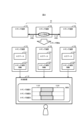
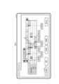
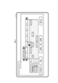
- a diagram showing the configuration of a log data analysis support system according to Embodiment 1. A diagram showing an overview of processing related to logging according to Embodiment 1
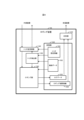
- a diagram showing the hardware configuration of the FA device according to Embodiment 1 A diagram showing a functional configuration of a logging device according to Embodiment 1
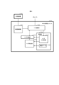
- a diagram showing an example of log data and logging period information according to Embodiment 1 A diagram showing a functional configuration of a central processing unit according to Embodiment 1.
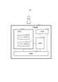
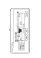
- a diagram showing a functional configuration of a support device according to Embodiment 1. A diagram showing a first example of a screen presented by the presentation unit according to Embodiment 1.
- a diagram showing a third example of a screen presented by the presentation unit according to Embodiment 1 A diagram showing a fourth example of a screen presented by the presentation unit according to Embodiment 1 A diagram showing a flow when starting up a system according to Embodiment 1
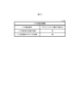
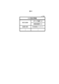
- a diagram showing an example of trigger setting information according to Embodiment 1 A diagram showing an example of trigger shared information according to Embodiment 1
- a diagram showing a flow of trigger sharing according to Embodiment 2 A diagram showing an example of trigger information according to Embodiment 2
- a diagram showing an example of event information according to Embodiment 3 A diagram showing an example of a screen presented by a presentation unit according to Embodiment 3 A diagram showing a flow of providing information to a support device according to Embodiment 4 A diagram showing an example of a condition input form according to Embodiment 4 A diagram showing an example of a screen presented by a presentation unit according to Embodiment 4 A diagram showing a first example of a screen presented by a presentation unit according to Embodiment 5. A diagram showing a second example of a screen presented by the presentation unit according to Embodiment 5.
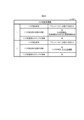
- Diagram for explaining trigger sharing according to Embodiment 6 A diagram showing a functional configuration of a network unit 24 according to a sixth embodiment Diagram for explaining a logging unit according to a modified example A diagram showing an example of trigger information according to Embodiment 7 A diagram showing an example of trigger sharing information according to Embodiment 7 A diagram showing an example of trigger information according to Embodiment 8 A diagram showing an example of trigger setting information according to Embodiment 8 A diagram showing an example of trigger information according to Embodiment 9
- First diagram for explaining the remaining number of relays according to the ninth embodiment Second diagram for explaining the remaining number of relays according to the ninth embodiment Diagram for explaining provision of support information according to Embodiment 10
- the log data analysis support system 100 is a system that supports a user in analyzing log data. As shown in FIG. 1, the log data analysis support system 100 includes a support device 10 that supports analysis by providing the user with information regarding log data recorded when controlling devices, and controlled devices 31 and 32. It has a PLC 20 to control, and logging devices 41 and 42 connected to the PLC 20 via an industrial network 400.
- the support device 10 is a computer typified by a PC having a UI (User Interface) function.
- the support device 10 is connected to the central processing unit 21 of the PLC 20 and communicates with each other via a communication line such as a USB (Universal Serial Bus) cable or a network such as a LAN (Local Area Network).
- the support device 10 provides the user with the ability to create, edit, and write a control program to be executed by the central processing unit 21 by executing application software called an engineering tool. Additionally, this engineering tool provides users with the ability to easily analyze log data that is distributed and stored in multiple logging devices.
- the PLC 20 includes a central processing unit 21 that realizes control of equipment by executing a control program, an input/output unit 22 that receives input from external equipment and outputs information to the external equipment, and a data logging unit. and a network unit 24 for connecting to an industrial network 400.
- Network unit 24 is connected to logging devices 41 and 42 via industrial network 400.
- PLC20 corresponds to an example of a programmable controller.
- the central processing unit 21, input/output unit 22, logging unit 23, and network unit 24 are connected to each other via the PLC bus 200 to transmit and receive signals.
- the PLC 20 is a function block type control device that includes a central processing unit 21, an input/output unit 22, a logging unit 23, and a network unit 24 mounted on a base unit (not shown).
- the central processing unit 21 executes a control program such as a ladder program to control the controlled devices 31 and 32 via the input/output unit 22. Specifically, the central processing unit 21 generates an operation command for the controlled device 32, which is a logging device, based on the input of sensing results from the controlled device 31, which is a sensor, and outputs it to the controlled device 32.
- the operation of the controlled device 32 executed by the operation command may be an operation different from logging, or may be logging.
- the central processing unit 21 controls a plurality of devices including controlled devices 31 and 32, and the plurality of devices work together to carry out, for example, transport, processing, and inspection of workpieces on a production line.
- the input/output unit 22 is connected to the controlled devices 31 and 32 via a signal line for transmitting a current signal or a voltage signal, or a cable for transmitting digital data.
- the logging unit 23 is a component unit of the PLC 20 and logs control data related to the control of devices by the PLC 20.
- the logging unit 23 has a function equivalent to that of the input/output unit 22, and may log control data input/output between devices connected to the logging unit 23 itself. Further, the logging unit 23 has the same function as the network unit 24, and may log control data sent and received via the industrial network. Furthermore, the logging unit 23 may log data shared with the central processing unit 21 via the PLC bus 200 without being connected to a device external to the PLC 20.
- the network unit 24 has a network interface circuit for connecting with the logging devices 41 and 42, and communicates with the central processing unit via the PLC bus 200, thereby allowing communication between the logging devices 41 and 42 and the central processing unit 21. to be relayed.
- the logging devices 41 and 42 may be devices controlled by the central processing unit 21, or may be other PLCs that control devices in cooperation with the PLC 20. Good too.
- each of the input/output unit 22, the logging unit 23, and the network unit 24 may be plural. Further, a plurality of central processing units 21 may be connected to the PLC bus 200 and may cooperate. The number of devices connected to the input/output unit 22 may be one or more than two. The number of devices connected to the network unit 24 via the industrial network 400 may be one or more than two.
- the logging unit 23, the controlled device 32, and the logging devices 41 and 42 have a function of logging control data.
- the controlled device 32 records data transmitted to and from the input/output unit 22 or data that changes in internal processing of the controlled device 32.
- the logging devices 41 and 42 each record data transmitted via the industrial network 400 or data used in internal processing of the logging devices 41 and 42.
- the logging unit 23 having a logging function, the controlled device 32, and the logging devices 41 and 42 may be each referred to as a logging device 50 without distinction.
- Logging by the logging device 50 means recording the history of control data handled by the logging device 50 regarding control of equipment.
- the control data is, for example, data stored in the memory of the logging device 50 at an address set in advance as a logging target.
- the history of control data is created by sequentially adding and writing values read from this address at preset intervals to a storage area for logging, and thus shows the transition of this value. The length of the period during which the control data is repeatedly read is determined in advance.
- the logging devices 51, 52, and 53 shown in FIG. 2 are each an example of the logging device 50. That is, each of the logging devices 51, 52, and 53 corresponds to one of the logging unit 23, the controlled device 32, and the logging devices 41, 42 shown in FIG.
- the logging device 52 when the logging device 52 detects a trigger indicating the start of logging, it shares the detected trigger with the logging devices 51 and 53.
- the logging devices 51 to 53 that share the trigger start generating log data 511, 521, and 531 almost simultaneously.
- Each of the log data 511, 521, and 531 may be generated based on logging that starts upon detection or reception of a trigger, or may be generated based on logging that is started upon detection or reception of a trigger, or upon detection of a trigger using data that is constantly logged in the ring buffer regardless of the presence or absence of a trigger. Alternatively, it may be generated using data before reception.
- the logging devices 51-53 start generating the log data 511, 521, 531, respectively.
- Logging period information 512, 522, and 532 indicating the logging period is generated and saved. Note that although the following explanation will focus on an example in which the timing of generating the logging period information 512, 522, 532 is immediately after the generation of the log data 511, 521, 531, the timing is not limited to this, and may be changed as desired. You can.
- the logging devices 51, 52, 53 Before providing log data 511, 521, 531, the logging devices 51, 52, 53 provide logging period information 512, 522, 532 to the support device 10 in response to a request from the support device 10.
- the support device 10 displays to the user a list of logging periods corresponding to the log data 511, 521, 531 that are distributed and stored in the logging devices 51 to 53. Make it easier for users to understand the corresponding logging period.
- the logging device 50 that notifies the logging period, the support device 10 that displays the logging period, and the central processing unit 21 that mediates communication between the logging device 50 and the support device 10 are each configured to function as a computer. Consists of hardware elements. Specifically, as shown in FIG. 3, the FA device 60, which corresponds to each of the logging device 50, the support device 10, and the central processing unit 21, includes a processor 61, a main storage section 62, an auxiliary storage section 63, It has an input section 64, an output section 65, and a communication section 66. The main storage section 62 , the auxiliary storage section 63 , the input section 64 , the output section 65 , and the communication section 66 are all connected to the processor 61 via an internal bus 67 .
- the processor 61 includes a CPU (Central Processing Unit) or an MPU (Micro Processing Unit) as a processing circuit.
- the processor 61 implements various functions by executing the program P1 stored in the auxiliary storage unit 63, and executes the processing described below.
- the program P1 of the support device 10 corresponds to the above-mentioned engineering tool
- the program P1 of the central processing unit 21 and the logging device 50 corresponds to firmware.
- the processor 61 of the central processing unit 21 executes a control program in addition to the program P1.
- the main storage unit 62 includes a RAM.
- the program P1 is loaded into the main storage section 62 from the auxiliary storage section 63.
- the main storage unit 62 is used as a work area for the processor 61.
- the auxiliary storage unit 63 includes nonvolatile memory represented by EEPROM (Electrically Erasable Programmable Read-Only Memory) and HDD (Hard Disk Drive).
- the auxiliary storage unit 63 stores various data used in processing by the processor 61 in addition to the program P1.
- the auxiliary storage unit 63 supplies data used by the processor 61 to the processor 61 according to instructions from the processor 61. Further, the auxiliary storage unit 63 stores data supplied from the processor 61.
- the input unit 64 includes input devices such as hardware switches, input keys, a keyboard, and a pointing device.
- the input unit 64 acquires information input by the user of the FA device 60 and notifies the processor 61 of the acquired information.
- the output unit 65 includes output devices such as an LED (Light Emitting Diode), an LCD (Liquid Crystal Display), and a speaker.
- the output unit 65 presents various information to the user according to instructions from the processor 61.
- the output section 65 may be configured integrally with the input section 64 as a touch screen.
- the communication unit 66 includes a network interface circuit for communicating with external devices.
- the communication unit 66 receives a signal from the outside and outputs data indicated by this signal to the processor 61. Furthermore, the communication unit 66 transmits a signal indicating data output from the processor 61 to an external device.
- the FA device 60 may have a plurality of communication sections 66.
- the FA device 60 that is the central processing unit 21 may separately include a communication section 66 for communicating with the support device 10 and a communication section 66 for communicating via the PLC bus 200.
- the logging device 50 includes a storage section 530 that stores various data, a trigger transmitting/receiving section 540 that transmits and receives a trigger signal indicating a trigger between external devices, and the logging device 50 itself. It includes a trigger detection section 550 for spontaneously detecting a trigger, a logging section 560 for generating log data, and a response section 570 for responding to requests from the support device 10.
- the logging device 50 corresponds to an example of a detection device that detects a trigger.
- the storage unit 530 is mainly realized by at least one of the main storage unit 62 and the auxiliary storage unit 63 of the logging device 50.
- the storage unit 530 stores trigger setting information 501 that is set in advance in the logging device 50 regarding triggers, and control data 502 used by the logging device 50.
- the trigger setting information 501 is information indicating conditions for detecting a trigger in the logging device 50. Further, the trigger setting information 501 indicates whether to accept trigger sharing from an external device and whether to notify the external device of the trigger detected by the logging device 50. Trigger setting information 501 is received by the logging device 50 from the outside in advance and stored in the storage unit 530. The reception of the trigger setting information 501 may be realized by the user's operation on the input unit 64 of the logging device 50, or the content of the user's operation on the support device 10 may be realized by the user's operation on the input unit 64 of the logging device 50. It may also be realized by being transmitted via a computer.
- the contents of the control data 502 change at any time as the PLC 20 controls the equipment.
- the control data 502 includes, for example, input data such as sensing results used for control, intermediate data generated in the process of processing the input values, and operations on the controlled device 32 generated from the input data or intermediate data. This corresponds to any control output data such as an instruction.
- the control data 502 may be a device value that is shared by a method such as so-called cyclic transmission among a plurality of devices that constitute a control system.
- the trigger transmitting/receiving section 540 is mainly realized by the cooperation of the processor 61 and the communication section 66 of the logging device 50.
- the trigger transmitter/receiver 540 determines whether or not the trigger indicated by the received trigger signal is to be output to the logging unit 560 based on the trigger setting information 501 .
- the trigger transmission/reception section 540 determines whether or not to transmit a trigger signal indicating the trigger to an external device based on the trigger setting information 501.
- the external device corresponds to the central processing unit 21 as described later, but may also include another logging device 50.
- the trigger detection unit 550 is mainly realized by the processor 61 of the logging device 50.
- Trigger detection section 550 monitors whether a condition defined by trigger setting information 501 is satisfied, and when determining that the condition is satisfied, notifies trigger transmission/reception section 540 and logging section 560 of the detection of a trigger.
- the condition for detecting a trigger may be that the value of the control data exceeds a threshold value, may be the receipt of an operation command from the central processing unit 21 indicating execution of logging, or may be any other condition. You can.
- the logging unit 560 is mainly realized by the processor 61 of the logging device 50.
- the logging section 560 When a trigger is input from either the trigger transmitting/receiving section 540 or the trigger detecting section 550, the logging section 560 periodically reads control data 502 to be logged that is set in advance and stores it in the storage section 530 as log data 503. Write. Additionally, the logging unit 560 creates logging period information 504 indicating the logging period during which the control data 502 was read to generate the log data 503, and writes it into the storage unit 530.
- each log data 503 is given a file name, and each log data 503 has the date and time when the control data was read and the address of the control data read from the storage unit 530. This is data that shows values in association with each other.
- the log data 503 may be a history of values read from a single address, or may be a history of values read from multiple addresses, as shown by "01.BIN" in FIG. It may be.
- the logging period information 504 is information that indicates, for each log data 503, the file name of the log data 503, the start date and time of the logging period, and the end date and time of the logging period in association with each other.
- the start date and time of the logging period information 504 is the date and time of the first recorded value included in the log data 503, and the end date and time is the date and time of the last recorded value included in the log data 503.
- the contents of the logging period information 504 are updated by adding a record corresponding to one line in FIG. 5 every time the log data 503 is generated.
- the response section 570 is mainly realized by the cooperation of the processor 61 and the communication section 66 of the logging device 50.
- the response unit 570 reads the logging period information 504 from the storage unit 530 in response to a request from the support device 10 and provides the logging period information 504 to the support device 10. Further, the response unit 570 reads the log data 503 from the storage unit 530 in response to a request from the support device 10 and provides the log data 503 to the support device 10.
- the central processing unit 21 stores a device communication section 211 for communicating with the support device 10, a bus communication section 212 for communicating via the PLC bus 200, and various data.
- the device communication section 211 and the bus communication section 212 are each mainly realized by the communication section 66 of the central processing unit 21.
- the central processing unit 21 corresponds to an example of a trigger relay unit that is connected to a plurality of detection devices and constitutes a programmable controller
- the bus communication section 212 corresponds to an example of a receiving means that receives a trigger signal.
- the storage section 213 is mainly realized by at least one of the main storage section 62 and the auxiliary storage section 63 of the central processing unit 21.
- the storage unit 213 stores trigger sharing information 2131 that is set in advance in the central processing unit 21 regarding trigger sharing, and control data 2132 used by the central processing unit 21.
- the trigger sharing information 2131 is information indicating conditions for detecting a trigger in the central processing unit 21 and a destination to which the trigger is shared.
- the trigger sharing destination is the logging device 50 that is set to receive the trigger from the outside, and is determined by referring to the trigger setting information 501 of each logging device 50, as will be described later.
- the contents of the control data 2132 change from time to time as the central processing unit 21 controls the equipment.
- the trigger relay section 214 is mainly realized by the processor 61 of the central processing unit 21.
- the trigger relay unit 214 receives a trigger signal from any of the logging devices 50 via the bus communication unit 212, the trigger relay unit 214 transmits the trigger signal to a sharing destination specified in the trigger sharing information 2131.
- the trigger relay section 214 transmits a trigger signal indicating the trigger to the sharing destination indicated by the trigger sharing information 2131.
- the trigger relay unit 214 corresponds to an example of a transmitting means that transmits a trigger signal.
- the trigger detection section 215 is mainly realized by the processor 61 of the central processing unit 21.
- the trigger detection unit 215 monitors whether a condition defined by the trigger sharing information 2131 is satisfied, and when determining that the condition is satisfied, notifies the trigger relay unit 214 of the detection of a trigger.
- FIG. 2 shows an example in which a trigger detected by one of the logging devices 50 is shared with other logging devices 50, a trigger detected by the central processing unit 21 is also shared with the logging devices 50. Ru. Note that the central processing unit 21 may be configured without the trigger detection section 215.
- the support device 10 includes a presentation unit 110 that presents information regarding log data 503 to the user, a reception unit 120 that receives input from the user, and a storage unit 130 that stores various information. It has a communication section 140 for communicating with the central processing unit 21.
- the presentation unit 110 is mainly realized by the cooperation of the processor 61 and the output unit 65 of the support device 10.
- the presentation unit 110 includes an online display unit 111 that displays information in an online state where the connection between the support device 10, the central processing unit 21, and each logging device 50 is established, and an online display unit 111 that displays information in an offline state where the connection is cut off. It has an offline display section 112 for displaying.
- the online display unit 111 displays a list of the logging periods of each logging device 50 on the screen 113 based on the logging period information 504 acquired from each logging device 50 via the communication unit 140.
- the online display unit 111 displays information as indicated by the logging period information 504 of each logging device 50 in a plane defined by a first axis corresponding to the list of logging devices 50 and a second axis corresponding to time. Display objects corresponding to the logging period. In the example of FIG. 8, a rectangular band-shaped icon is displayed with hatching as an object indicating the logging period.
- the position of the object on the first axis indicates a device ID (Identifier) for identifying the logging device 50 that executed logging in the logging period, and the width of the object on the second axis indicates the range of the logging period.
- a number equal to the code of each logging device 50 is shown as the device ID.
- the device ID may be any information that can identify the logging device 50, such as an IP (Internet Protocol) address, a MAC (Media Access Control) address, a station number in the industrial network 400, another number, or a combination thereof. It may be.
- the reception unit 120 selects the logging period corresponding to the objects 71. Accepted.
- the communication unit 140 requests the logging device 50 to obtain log data corresponding to the selected logging period.
- the logging unit 23 is requested for log data 503 generated by logging during the logging period from 12:00 to 13:00, and the log data 503 is requested from the controlled device 32 from 12:00 to 13:00.
- Log data 503 generated by logging during the logging period up to 13:00 is requested.
- the offline display unit 112 displays information regarding the log data 503 imported into the support device 10. For example, the offline display unit 112 displays a list of corresponding logging periods on the screen 113 as shown in FIG. 10 for the log data acquired from the logging device 50 according to the selection shown in FIG. The offline display unit 112 displays the logging period in the same way as the online display unit 111 displays the logging period. That is, the offline display unit 112 displays objects corresponding to the captured log data within a plane defined by the vertical axis corresponding to the list of the logging device 50 and the horizontal axis corresponding to the time.
- the offline display section 112 displays details of the log data 503 corresponding to the selected object, as shown in FIG. Display.
- three graphs showing changes in values included in the log data 503 are displayed using a common time axis.
- the reception unit 120 is mainly realized by the processor 61 and the input unit 64 of the support device 10.
- the storage unit 130 is mainly realized by the auxiliary storage unit 63 of the support device 10.
- the storage unit 130 stores logging period information 504 and log data 503 acquired from the logging device 50, and the storage unit 130 provides these logging period information 504 and log data 503 in response to a request from the presentation unit 110. do.
- the communication unit 140 is mainly realized by the cooperation of the processor 61 and the communication unit 66 of the support device 10.
- the communication unit 140 acquires logging period information 504 from the logging device 50 and provides it to the presentation unit 110 and the storage unit 130.
- the communication unit 140 also acquires log data 503 corresponding to the logging period selected by the reception unit 120 from the logging device 50, and transfers the acquired log data 503 to the presentation unit 110 and the storage unit 130. Provided to.
- FIG. 12 shows a flow for preparing to share triggers when starting up the log data analysis support system.
- the logging device 50 refers to the trigger setting information 501 stored in the storage unit 530 of the logging device 50 itself (step S11).
- Trigger setting information 501 indicates trigger detection conditions, presence or absence of transmission when a trigger is detected, and presence or absence of logging when a trigger is received.
- the logging device 50 determines whether or not the trigger setting information 501 referenced in step S11 specifies that a trigger should be transmitted and received (step S12). Specifically, the logging device 50 performs the determination in step S12 if at least one of the following is specified: that transmission is to be performed when a trigger is detected, and that logging is to be performed when a trigger is received. affirm.
- step S12 If the determination in step S12 is affirmative (step S12; Yes), the logging device 50 outputs the trigger setting information 501 to the central processing unit 21 (step S13).
- the output of the trigger setting information 501 may be sending the trigger setting information 501 to the central processing unit 21, or storing the trigger setting information 501 in a storage device that can be referenced by the central processing unit 21.
- step S12 On the other hand, if the determination in step S12 is negative (step S12; No), that is, if it is specified that the trigger is neither transmitted nor received, the logging device 50 does not output the trigger setting information 501.
- the central processing unit 21 acquires the trigger setting information 501 provided from each logging device 50 (step S14), and updates the trigger shared information 2131 (step S15). Specifically, as shown in FIG. 14, each logging device 50 that outputs the trigger setting information 501 determines whether or not to transmit a trigger signal, and receives a trigger signal from the outside and executes the logging process. The trigger sharing information 2131 is changed to indicate whether or not to do so. Thereby, the trigger sharing information 2131 indicates the logging device 50 that can serve as a trigger signal transmission source and the logging device 50 that can serve as a trigger signal sharing destination.
- the central processing unit 21 inquires of each logging device 50 about the model or model number of the logging device 50, and determines whether the model or model number of the logging device 50 has a function related to trigger sharing or trigger signal transmission/reception. You may also check whether Then, if the trigger setting information 501 is provided from the logging device 50 of a model or model number that does not have such a function, the central processing unit 21 indicates that the trigger setting information 501 has been set incorrectly. An error may be output.
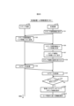
- FIG. 15 shows the flow when sharing the trigger signal issued by the logging device 51.
- the logging device 51 determines whether a trigger signal has been received (step S21). If it is determined that the trigger signal has not been received (step S21; No), the logging device 51 determines whether or not a trigger has been detected (step S22). If it is determined that a trigger has not been detected (step S22; No), the logging device 51 repeats the processing from step S21 onwards, and monitors whether a trigger signal is received or not and whether a trigger is detected.
- step S22 If it is determined in step S22 that a trigger has been detected (step S22; Yes), the logging device 51 should refer to the trigger setting information 501 from the storage unit 530 and transmit a trigger signal to the trigger setting information 501. It is determined whether or not this is specified (step S23). If it is determined that the trigger signal should be transmitted (step S23; Yes), the logging device 51 transmits the trigger signal to the central processing unit 21 (step S24).
- step S21 determines whether the trigger setting information 501 specifies that the trigger signal should be received and the logging process should be executed. It is determined whether or not (step S25). If it is determined that it is specified that the logging process should be executed upon receiving the trigger signal (step S25; Yes), and if it is determined that it is not specified that the trigger signal should be transmitted in step S23. In this case (step S23; No), and after the end of step S24, the logging device 51 executes the logging process according to the trigger setting information 501 (step S26). As a result, log data 503 is generated.
- the logging device 51 generates logging period information 504 indicating the logging period of the log data 503 generated in step S26 (step S27). Specifically, the logging device 51 generates a record indicating the logging period and adds it to the logging period information 504.
- step S25 If it is determined in step S25 that it is not specified that the logging process should be performed upon receiving the trigger signal (step S25; No), the logging device 51 does not perform logging.
- the central processing unit 21 receives the trigger signal and relays the trigger signal according to the trigger sharing information 2131 (step S28). Specifically, the trigger signal is transmitted to the logging device 50 that is indicated in the trigger sharing information 2131 to receive the trigger signal and execute the logging process.
- a logging device 52 is representatively shown as the logging device 50 to which the trigger signal from the central processing unit 21 is transmitted.
- the logging device 52 When the logging device 52 receives the trigger signal from the central processing unit 21, it is specified that the logging device 52 should execute the same processing as steps S21 to S25, receive the trigger signal, and execute the logging process. If so, logging processing is executed (step S29), and logging period information 504 is generated (step S210). As a result, the logging devices 51 and 52 work together to generate log data 503 and logging period information 504.
- the logging device 52 does not need to execute the logging process when the trigger setting information 501 does not specify that the logging process should be executed upon receiving the trigger signal.
- the central processing unit 21 transmits the trigger signal to the logging device 50 that receives the trigger signal and executes the logging process, but the trigger setting of the logging device 52 is performed in the startup flow shown in FIG. If the trigger setting information 501 of the logging device 52 is changed after the information 501 is reflected in the trigger sharing information 2131, the logging device 52 that was the sharing destination of the trigger signal will not log the trigger signal even if it receives the trigger signal. I will not do it.
- the logging device 52 is shown to execute steps S29 and S210 in FIG. It is a step. That is, the logging device 52 executes the same steps S21 to S27 as the logging device 51. Further, each of the logging devices 51 and 52 may be any one of the plurality of logging devices 50.
- FIG. 16 shows a flow when a trigger detected by the central processing unit 21 is shared.
- the central processing unit 21 determines whether or not a trigger has been detected (step S31), and if it is determined that a trigger has not been detected (step S31; No), this determination is repeated. The presence or absence of a trigger is monitored by this. On the other hand, if it is determined that a trigger has been detected (step S31; Yes), the central processing unit 21 transmits a trigger signal according to the trigger sharing information 2131 (step S32).
- the logging device 50 receives the trigger signal transmitted in step S32, and if the trigger setting information 501 specifies that the trigger signal should be received and the logging process should be executed, the logging device 50 executes the logging process.
- the process is executed (step S33), and logging period information 504 is generated (step S34).
- FIG. 17 shows trigger sharing processing for sharing triggers, which is executed by the central processing unit 21.
- the central processing unit 21 determines whether a trigger signal has been received from the outside (step S41). If it is determined that the trigger signal has not been received (step S41; No), the central processing unit 21 determines whether a trigger has been detected within the central processing unit 21 (step S42). If it is determined that no trigger has been detected (step S42; No), the central processing unit 21 repeats the processing from step S41 onwards. Thereby, the central processing unit 21 monitors whether or not a trigger signal is received and whether or not a trigger is detected.
- step S41 If it is determined that a trigger signal has been received in step S41 (step S41; Yes) and if it is determined that a trigger has been detected in step S42 (step S42; Yes), the central processing unit 21 A trigger signal is transmitted to the logging device 50 (step S43). After that, the central processing unit 21 repeats the processing from step S41 onwards.
- the central processing unit 21 when the central processing unit 21 receives a trigger signal indicating a trigger or detects a trigger, the central processing unit 21 completes sharing the received trigger or detected trigger to the logging device 50, and then starts the next trigger. Execute related processing. In other words, when multiple triggers occur almost simultaneously, the central processing unit 21 shares only the first trigger with the logging device 50 and does not share the other triggers with the logging device 50.
- FIG. 18 shows a flow for providing the generated log data 503 and logging period information 504 to the support device 10.
- the support device 10 requests each logging device 50 connected via the central processing unit 21 to transmit logging period information 504 in accordance with a specific operation from the user (step S51). ).
- the specific operation is, for example, inputting an instruction to start log data analysis in the engineering tool.
- the request for the logging period information 504 may include a specification of the time to be displayed on the screen 113.
- the specified time may be a specific point in time or a time range.
- the support device 10 specifies the most recent seven hours and uses logging period information 504 indicating a logging period that overlaps with a time within the seven hours. Request a record of.
- the support device specifies a time range from 10:00 to 17:00 as shown in FIG. 8, and performs logging that falls within the time range.
- a record of logging period information 504 indicating a period and a record of logging period information 504 indicating a logging period that partially overlaps with the time range are requested.
- a logging period that is included in a time range means a period that includes both a start time and an end time within the time range.
- a logging period that partially overlaps with a time range means a period in which one of the start time and end time is included in the time range and the other is not included. If there is a record of logging period information 504 indicating a logging period with a start time of 9:30 and an end time of 10:30 for the time range from 10:00 to 17:00 as illustrated in FIG. , the record will also be requested.
- the logging device 50 Upon receiving the request from the support device 10, the logging device 50 transmits the logging period information 504 in response to this request (step S52). Specifically, the response unit 570 of the logging device 50 receives an inquiry from the support device 10, and if the logging period indicated by the logging period information 504 includes a specified time, the response unit 570 of the logging device 50 responds to the logging period information 504 as a response to the inquiry. A part or all of the information is provided to the support device 10. Here, if a plurality of records of the logging period information 504 include the specified time, the plurality of records may be provided. The communication unit 140 of the support device 10 then acquires the logging period information 504 (step S53).
- the presentation unit 110 of the support device 10 presents the logging period indicated by the logging period information 504 acquired in step S53 to the user (step S54). As a result, a screen 113 as shown in FIG. 8 is displayed.
- the reception unit 120 of the support device 10 accepts the user's selection of one of the presented logging periods (step S55).
- selection of the logging period essentially means selection of a combination of the logging device 50 and the logging period of logging by the logging device 50.
- the support device 10 requests the logging device 50 that executed logging in the selected logging period to provide log data 503 corresponding to the selected logging period.
- the logging device 50 Upon receiving this request, the logging device 50 transmits the requested log data 503 to the support device 10 (step S56). Thereby, the communication unit 140 of the support device 10 acquires the log data 503 generated during the specified logging period by the logging device 50 specified by the user (step S57).
- the support device 10 determines whether the user has input an instruction to start offline analysis (step S58). If it is determined that an instruction has been input (step S58; Yes), the presentation unit 110 of the support device 10 presents the logging period for the acquired log data 503 (step S59). As a result, the screen 113 as illustrated in FIG. 10 is displayed in the same display format as before the log data 503 was acquired. Then, the support device 10 supports the user's analysis of the log data 503 by displaying details of the log data 503 according to the user's instructions (step S510). For example, the support device 10 displays a screen 113 as illustrated in FIG. 11. Note that if it is determined in step S58 that no instruction has been input (step S58; No), the support device 10 repeats the determination in step S58 and waits for the input of an instruction.
- the plurality of logging devices 50 work together to execute the logging process by sharing a trigger.
- analyzing log data there is a desire to generate log data 503 simultaneously by a plurality of logging devices 50 and to use these log data 503 as targets for analysis.
- FIG. 19 it is desirable to analyze a plurality of log data 503 in order to verify the operation of a plurality of devices after the fact at the time when an abnormality occurred.
- triggers are not shared, it is necessary to set triggers in advance for multiple logging devices 50 so that logging is linked, and such setting is generally difficult.
- the setting work is not very difficult, but if the number increases to 5, 6, or several tens, it is simple to set up the logging device. It takes time and effort to sequentially set similar information in each device 50, making the work complicated. Further, when a plurality of logging devices 50 are connected across a network, it may be necessary to change the network settings in order to make these logging devices 50 work together. Furthermore, when information is set by different persons for each of the logging devices 50 that constitute the log data analysis support system 100, it is difficult to modify the information set for the logging device 50 itself.
- logging in overlapping logging periods can be easily realized by having the logging devices 50 share a trigger.
- the support device 10 acquires logging period information 504 from each of the logging devices 50, and determines in what logging period the data was generated. A list of the logging devices 50 in which the log data 503 is stored is displayed to the user.
- the log data analysis support system 100 by displaying a list of logging periods as described above, the user can view the log data 503 by simply visually checking one screen 113. It is possible to check the outline and select log data 503 necessary for analysis. In particular, in analyzing the log data 503, the log data 503 generated at a specific time or within a specific time range is often targeted, so it is effective to present the logging period for each logging device 50. Therefore, the preparation work for log data analysis can be reduced.
- the sharing range of the trigger signal in the log data analysis support system 100 is determined by the trigger setting information 501 set in advance in the logging device 50. Specifically, whether or not the logging device 50 that has detected the trigger transmits a trigger signal is determined by the trigger setting information 501 of the logging device 50. The destination of this trigger signal is determined based on the trigger setting information 501 of the other logging device 50. That is, the trigger signal is relayed by the central processing unit 21 to the logging device 50 having the trigger setting information 501 specifying that the trigger signal is to be received and the logging process is executed.
- the trigger setting information 501 may specify either whether a trigger signal is transmitted or not, or whether a trigger signal is received.
- the trigger setting information 501 specifies whether or not a trigger signal is transmitted, but does not specify whether or not a trigger signal is received, a trigger signal transmitted from one of the logging devices 50 is broadcast to all other logging devices 50. be done. If the trigger setting information 501 specifies whether or not a trigger signal is received, but does not specify whether or not a trigger signal is transmitted, any logging device 50 that detects a trigger transmits a trigger signal, and the central processing unit 21 The trigger signal is relayed to the logging device 50 that is specified to accept the signal.
- Trigger sharing information 2131 that defines whether each logging device 50 is authorized to transmit and receive trigger signals may be directly set in advance in the central processing unit 21.
- the setting of this trigger sharing information 2131 may be realized by the central processing unit 21 accepting a user operation on the input section 64 of the central processing unit 21, or by the central processing unit 21 accepting a user operation on the support device 10. This may be realized by receiving the information via the communication unit 66.
- each logging device 50 that has detected a trigger transmits a trigger signal to the central processing unit 21, and the central processing unit 21 receives the trigger signal when the logging device 50 that has transmitted the trigger signal has transmission authority. may be relayed to another logging device 50 that has reception authority.
- the support device 10 Before acquiring the log data 503, the support device 10 generates an object corresponding to the logging period in the plane defined by the first axis corresponding to the list of the logging device 50 and the second axis corresponding to the time. Arrange and display. Further, the support device 10 also arranges a similar object for the acquired log data 503 to present the logging period. This arrangement of objects allows the user to easily recognize the logging device 50 in which each piece of log data 503 is stored and the logging period in which the log data 503 was generated.
- the support device 10 when the support device 10 receives the selection of two or more logging periods and acquires two log data 503, the support device 10 includes, as details of the two log data 503, changes in values indicated by each of the log data 503. It is displayed on a common time axis as shown in FIG. This allows the user to efficiently analyze the log data 503.
- the number of logging periods to be selected may be one or more than two.
- the number of log data corresponding to the logging period may be one or more than two.
- the central processing unit 21 when the central processing unit 21 receives a trigger signal, it does not perform any other trigger-related processing until the relay of the trigger signal is completed.
- the central processing unit 21 when a first trigger signal, a second trigger signal, and a third trigger signal are simultaneously transmitted from a plurality of logging devices 50, the central processing unit 21 can transmit the first trigger signal, the second trigger signal, and the third trigger signal. The transmission of one trigger signal is relayed, and the other trigger signals are excluded from the relay target. This makes it possible to avoid bandwidth compression due to relaying a large number of trigger signals.
- a logging device 50 that transmits a first trigger signal corresponds to an example of a first detection device
- a logging device 50 that transmits a second trigger signal corresponds to an example of a second detection device.
- the trigger relay section 214 of the central processing unit 21 is a transmitting means that transmits the first trigger signal to a second detection device different from the first detection device when the first trigger signal is received, and A second trigger signal different from the first trigger signal received by the receiving means from the time when the first trigger signal is received by the means until the transmission of the first trigger signal by the transmitting means is completed is excluded from the transmission target.
- This corresponds to an example of a transmitting means.
- the log data analysis support system 100 corresponds to an example of a trigger transmission system
- the procedures shown in FIGS. 17 and 21 correspond to an example of a trigger transmission method.
- the destination of the first trigger signal is equal to the logging devices 50 within the shared range, and may be all the logging devices 50 connected to the central processing unit 21, or the destinations of the first trigger signal may be all the logging devices 50 connected to the central processing unit 21, or two including the second detection device.
- the logging device may be more than
- relaying of other trigger signals is not executed until the relay processing of one trigger signal executed in the central processing unit 21 is completed.
- the end point of the interruption period during which the central processing unit 21 starts relaying one trigger signal and then suspends the relaying of another trigger signal is when the relay processing executed in the central processing unit 21 is completed. Ta.
- the end point of the suspension period may be changed to any other timing.
- the end of the suspension period may be the timing at which the relayed trigger signal reaches the destination logging device 50. Specifically, this timing may be the timing at which the relayed trigger signal reaches at least one destination logging device 50, or the timing at which the relayed trigger signal reaches all destinations. Good too.
- the logging device 50 may transmit a reception signal indicating that the trigger signal has been received to the central processing unit 21, and the central processing unit 21 may end the suspension period based on the reception signal.
- the end of the suspension period may be the timing at which logging by the logging device 50 that has received the relayed trigger signal is completed. Specifically, this timing may be the timing when at least one logging device 50 that has received the trigger signal has completed logging, or the timing when all the logging devices 50 that have received the trigger signal have completed logging. You can.
- the logging device 50 may transmit a completion signal indicating that logging has been completed to the central processing unit 21, and the central processing unit 21 may end the suspension period based on the completion signal.
- the length of the interruption period may be predetermined, for example, as 5 minutes or 10 minutes. When the length of the interruption period becomes longer, it is possible to prevent congestion that would cause a trigger signal to loop in a large-scale log data analysis support system 100 that includes a large number of devices.
- the length of the suspension period may be at least longer than the period until the central processing unit 21 completes the relay processing of the trigger signal first received at a timing other than the suspension period.
- the log data 503 is generated by repeatedly reading the value of control data from a specific address.
- the address from which the control data is read may be an identifier of a physical storage area of a storage device, or an identifier of a logical storage area handled by software including firmware and an OS (Operating System). You can.
- the address of the control data may be identification information for distinguishing the value whose transition is recorded as the log data 503 from other values.
- the address of the control data may be a device in a PLC, or a "variable” or "label” handled in a programming language such as FBD (Function Block Diagram) language.
- Embodiment 2 Next, Embodiment 2 will be described, focusing on the differences from Embodiment 1 described above. Note that for the same or equivalent configurations as those of the first embodiment, the same reference numerals are used.
- the trigger simply indicates the start of logging has been described, but it is conceivable to focus on the trigger to further support the user's analysis of the log data 503. In the following, a method to further assist the user with regard to triggers will be described.
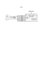
- trigger information regarding the trigger is added to the trigger signal and log data. Specifically, as shown in FIG. 22, when the determination in step S23 is affirmative (step S23; Yes), the logging device 51 attaches trigger information to the trigger signal and transmits it to the central processing unit 21 (step S61). As shown in FIG. 23, the trigger information includes shared information indicating a destination to which the trigger is shared, and a trigger ID for identifying the trigger.
- the trigger ID is determined based on, for example, the identification information of the device that detected the trigger and the detection time of the trigger, but is not limited to this, and may be any unique identifier for each trigger.
- the shared information is defined in the trigger setting information 501 along with the fact that a trigger signal is to be transmitted when a trigger is detected.
- the upper part of FIG. 24 shows that when the first trigger is detected, the sharing destination is limited to "only those managed by the central processing unit 21", and the lower part of FIG. 24 shows that when the second trigger is detected, Indicates that the shared destination is all devices.
- the PLC 20 includes central processing units 21 and 21a, the central processing unit 21 manages a logging device 51, and the central processing unit 21a manages a logging device 52 different from the logging device 51. It may be targeted.
- this trigger is moved to the center along with the logging device 51 that detected the trigger, as shown by the solid arrow in FIG. It is shared with other logging devices 51 managed by the processing unit 21, but not with the logging device 52.
- the central processing unit 21 limits the destination of the trigger signal to the logging device 51.
- this trigger is shared by all the logging devices 51 and 52, as shown by the dashed arrow in FIG. In this way, the trigger sharing range can be controlled by the setting contents of the trigger setting information 501.
- the logging device 51 executes logging processing (step S26), generates logging period information 504, and converts the trigger information added to the trigger signal in step S61 into the logging period information. 504 as well (step S62). Specifically, trigger information is stored in association with a record added to the logging period information 504.
- the central processing unit 21 Upon receiving the trigger signal and trigger information transmitted in step S61, the central processing unit 21 relays the trigger signal and trigger information according to the trigger shared information 2131 (step S63).
- the sharing destination specified by the trigger sharing information 2131 is different from the sharing destination indicated by the sharing information of the trigger information, it may be predetermined that one of the sharing destinations is given priority,
- the trigger signal may be transmitted only to destinations that have been designated as sharing destinations. Further, since the sharing destination is defined by the trigger information, the selection of the sharing destination based on the trigger sharing information 2131 may be omitted. That is, the central processing unit 21 may relay the trigger signal based on the trigger information without storing the trigger sharing information 2131.
- the logging device 52 that has received the trigger signal and trigger information from the central processing unit 21 executes step S29, generates logging period information 504, and adds the received trigger information to the logging period information 504 ( Step S64).
- step S29 whether or not to execute it may be determined depending on the contents of the trigger setting information 501 of the logging device 52, or all the logging devices 52 to which the trigger signal has reached as a sharing destination, regardless of the trigger setting information 501. You can also run it without doing anything.
- FIG. 26 shows a flow in which the support device 10 acquires the trigger information along with the logging period information 504. Specifically, when the support device 10 requests the logging period information 504, the logging device 50 transmits the logging period information 504 and the trigger information attached to the logging period information 504 (step S65). When the support device 10 acquires the logging period information 504 and the trigger information (step S66), it presents the logging period together with the trigger information to the user (step S67).
- the user presses the button 721 that instructs to display the trigger ID on the screen 113, a line indicating the timing at which the trigger occurred is displayed on the object corresponding to each logging period.
- the trigger ID of the trigger is displayed in an overlapping manner.
- the user can confirm that the log data corresponding to the two objects 722 were both generated by the trigger with the trigger ID "TRIG001", but for the object 723 whose time range overlaps with the object 722, It can be easily understood that the trigger was generated by a trigger having a different trigger ID of "TRIG302".
- a common trigger ID is displayed for the log data 503 that is logged by sharing a trigger, the scope of sharing the trigger can be easily recognized from the screen 113 in FIG. 27.
- the timing at which the trigger occurs in FIG. 27 may be indicated by trigger information.
- the trigger information indicates the trigger generation timing, it indicates the trigger generation timing in addition to the shared information and trigger ID shown in FIG. 23.
- the trigger generation timing may be specified by a method of generating log data 503 based on a trigger in the logging device 50. For example, when the logging device 50 reads control data and generates the log data 503 immediately after a trigger occurs or immediately after receiving a trigger signal, the start point of the logging period corresponds to the trigger generation timing.
- the logging device 50 constantly reads control data regardless of the presence or absence of a trigger, temporarily stores it in a ring buffer, and uses this ring buffer to read the control data a certain period of time before the trigger occurs or the trigger signal is received.
- the log data 503 is generated using the control data obtained as a starting point, the time when the certain period of time has elapsed from the start of the logging period corresponds to the trigger generation timing.
- the method for generating the log data 503 may be stored in advance in the support device 10, or may be obtained by the support device inquiring the logging device 50 as needed.
- the support device 10 may indicate an arbitrary timing within the logging period as the trigger occurrence time, or may indicate only the trigger ID as the logging period without indicating the trigger occurrence time. They may be displayed in correspondence. Specifically, the support device 10 may display the trigger ID without showing the line corresponding to the trigger occurrence time in FIG. 27.
- the user can be further supported by using the shared information and the trigger information including the trigger ID.
- the sharing range of trigger signals can be flexibly controlled using trigger information. Note that either the shared information or the trigger ID may be omitted from the trigger information.
- the trigger information may be embedded in the trigger signal and the trigger signal indicating the trigger information may be transmitted.
- the trigger ID corresponds to an example of trigger identification information for identifying a trigger from other triggers.
- Embodiment 3 Next, Embodiment 3 will be described, focusing on the differences from Embodiment 1 described above. Note that for the same or equivalent configurations as those of the first embodiment, the same reference numerals are used.
- This embodiment differs from Embodiment 1 in that an event history other than the log data 503 is presented to the user together with the logging period.
- the communication unit 140 acquires event information and stores it in the storage unit 130.
- the event information is information that shows an event ID for identifying an event, an event occurrence date and time, an event type, and event details in association with each other.
- An event is an event related to control of a device by the PLC 20, and is, for example, detection of an abnormality, occurrence of an error, or other predetermined event.
- the provider of event information is arbitrary. Specifically, the event information may be provided from the central processing unit 21, the logging device 50, or another device. Further, when an event occurs, the user may directly input event information to the reception unit 120.
- the presentation unit 110 refers to event information from the storage unit 130 and displays a triangular object 731 indicating the time of occurrence of the event. Furthermore, when the object 731 is selected by the user, the presentation unit 110 displays an area 732 that displays details of the event.
- the support device 10 indicates the time of the event as well as the logging period. This allows the user to easily select the log data 503 generated before and after the occurrence of an event.
- Embodiment 4 Next, Embodiment 4 will be described, focusing on the differences from Embodiment 1 described above. Note that for the same or equivalent configurations as those of the first embodiment, the same reference numerals are used.
- the user had to check the logging period of each logging device 50 and select the log data 503 to be acquired.
- the log data 503 to be acquired may depend on control data included in the log data 503. In such a case, acquiring a large amount of log data 503 and searching for control data puts pressure on the line and takes time. Therefore, a method of checking the control data included in the log data 503 to some extent before acquiring the log data 503 will be described below.
- the support device 10 accepts specification of conditions for control data to be searched from the log data 503 (step S71). Specifically, the presentation unit 110 displays a condition input form as shown in FIG. 31, and the reception unit 120 receives input of conditions specified by the user.
- the support device 10 notifies the logging device 50 of the conditions in step S71 (step S72), and the logging device 50 searches the log data 503 for control data that matches the conditions (step S73). Then, the logging device 50 transmits search result information indicating the search results to the support device 10 (step S74).
- the search result includes the found control data and the recording date and time of the control data. Further, a search result in which control data matching the conditions is not found indicates that no control data is found.
- the support device 10 presents the search result information received from the logging device 50 to the user (step S75). For example, as shown in FIG. 32, the presentation unit 110 displays an object 741 indicating the recording date and time of the discovered control data along with an object indicating the logging period.
- the logging device 50 searches the log data 503 for control data that satisfies the conditions specified by the user, and the search results are presented by the presentation unit 110. Ru.
- log data 503 including control data that satisfies a specific condition is to be analyzed, neither a large number of log data 503 nor large log data 503 is sent to the support device 10. Users can easily search for such control data.
- Embodiment 5 will be described, focusing on the differences from Embodiment 1 described above. Note that for the same or equivalent configurations as those of the first embodiment, the same reference numerals are used. This embodiment differs from Embodiment 1 in that the user can mark any time on the logging period information 504 and log data 503.
- the reception unit 120 calculates the time corresponding to the mark, and calculates the time corresponding to the mark. It is stored in the storage unit 130 together with the mark ID. As shown in FIG. 34, this mark indicates the time calculated as described above for the change in the value of each log data 503 on the screen 113 showing details of two or more log data 503.
- the user can add marks, it can be useful for the user's analysis of the log data 503. Specifically, when examining the trends of each of a plurality of pieces of control data in detail, the user can specify a common timing of interest and easily observe fluctuations in the control data around that timing. can.
- Embodiment 6 will be described, focusing on the differences from Embodiment 2 described above. Note that for the same or equivalent configurations as in the second embodiment, the same reference numerals are used.
- This embodiment differs from Embodiment 2 in that a trigger is shared between a logging device 50 managed by a PLC 20 and a logging device 50 connected to the PLC 20 via an industrial network 400. different.
- the PLC 20 and the controlled device 32 share the trigger using shared information, and the sharing range of the trigger is determined according to the shared information. Furthermore, in the industrial network 400, triggers are shared with trigger information added.
- the central processing unit 21 was mainly explained as an element having the function of relaying the trigger signal, but in the present embodiment, the network unit 24 is also explained as shown in FIG. It has the same function as the central processing unit 21 regarding trigger signal relay.
- the trigger detection section 214 and the trigger detection section 215 function in the same manner.
- the communication unit 242 transmits and receives trigger signals via the PLC bus 200 and the industrial network 400.
- the network unit 24, like the central processing unit 21, has a hardware configuration as an FA device as shown in FIG.
- the network unit 24 corresponds to an example of a trigger relay unit that constitutes a programmable controller.
- the communication unit 242 corresponds to an example of a receiving unit that receives a trigger signal
- the trigger relay unit 244 corresponds to an example of a transmitting unit that transmits a trigger signal.
- the central processing unit 21 relays a trigger signal received via the PLC bus 200 from one unit constituting the PLC 20 to another unit via the PLC bus 200, whereas the network unit 24 A trigger signal received from the device via the PLC bus 200 or the industrial network 400 is relayed to another device via the PLC bus 200 or the industrial network 400.
- the network unit 24 when the network unit 24 receives a trigger signal from the PLC bus 200, it adds trigger information to the trigger signal and transmits the trigger signal to the logging devices 41 and 42 on the industrial network 400. Further, when the network unit 24 receives a trigger signal from the logging device 41, the network unit 24 transmits the trigger signal to a unit connected to the logging device 42 and the PLC bus 200 using the trigger information attached to the trigger signal. Send.
- the network unit 24 executes processing equivalent to the trigger sharing processing of the central processing unit 21 shown in FIG. 17. For this reason, the network unit 24, like the central processing unit 21, provides an interruption period from the time when one trigger signal is received, during which it does not relay even if another trigger signal is received. If the network unit 24 does not have the function of detecting a trigger, step S42 may be omitted from the trigger sharing process shown in FIG. 17.
- the network unit 24 is It may have the same relay-related functions as 21.
- the logging unit 23 of the PLC 20 may be configured without the function of receiving a trigger. That is, as shown in FIG. 37, the logging unit 23 has a trigger transmitter 540a instead of the trigger transmitter/receiver 540, and when a trigger is detected, transmits a trigger signal and the central processing unit 21 The trigger signal may be broadcast to the logging devices 41, 42 via the industrial network 400.
- Embodiment 7 Next, Embodiment 7 will be described, focusing on the differences from Embodiment 2 described above. Note that for the same or equivalent configurations as in the second embodiment, the same reference numerals are used.
- the trigger information received by the central processing unit 21 indicates the issuer of the trigger, the source and destination of the trigger signal, and the sharing range of the trigger signal is determined based on the trigger information. , which is different from the second embodiment.
- This trigger information corresponds to an example of first trigger information.
- the trigger information indicates, as shared information, the issuer of the trigger, the source of the trigger signal, and the destination of the trigger signal. Issuer means the device that detected the trigger or the device that originally sent the trigger signal.
- This trigger information is added to the trigger signal by the logging device 50 that detected the trigger and generated the trigger signal.
- the "transmission source" of the trigger information is rewritten by the device that transmits the trigger signal between the logging device 50 and the central processing unit 21 to information indicating the device.
- trigger information is generated when a trigger is detected by the logging device 41, is transmitted via the network unit 24, and is received by the central processing unit 21.
- the central processing unit 21 determines the destination of the trigger signal based on this trigger information and preset trigger sharing information 2131.
- the central processing unit 21 refers to trigger sharing information 2131 as illustrated in FIG. 39 .
- This trigger sharing information 2131 indicates a device that is an issuer for transmitting a trigger signal as an issuer condition, and indicates a device that is a source for transmitting a trigger signal as a source condition.
- the central processing unit 21 determines that the issuer indicated by the trigger information matches the issuer conditions specified in the trigger shared information 2131, and the sender indicated by the trigger information meets the sender conditions specified in the trigger shared information 2131. If the original condition is met, a trigger signal is transmitted to the destination indicated by the trigger information.
- the trigger signal transmitted by the central processing unit 21 may or may not be provided with trigger information.
- the logging device 50 receives the trigger signal from the central processing unit 21 and logs the control data.
- the sharing range of the trigger signal is determined by the issuer, transmitter, and destination indicated by the trigger information received by the central processing unit 21. This makes it possible to flexibly control the trigger signal sharing range.
- the central processing unit 21 may transmit a trigger signal to the destination indicated by the trigger information.
- the trigger information may be information indicating any one or two of the issuer, the sender, and the destination. That is, the sharing range of the trigger signal may be determined based on trigger information in which any one or two of the issuer, transmitter, and destination shown in FIG. 38 are omitted. If the destination is omitted, the central processing unit 21 sends a trigger signal to all the connected logging devices 50 when one or both of the conditions regarding the issuer and the sender are satisfied. Just send it.
- whether or not the logging device logs control data based on a trigger detected by the detection device depends on the content of the relay setting information and the trigger signal transmitted from the detection device.
- the trigger signal is determined by whether or not the central processing unit transmits a trigger signal to the logging device according to at least one of the contents of the first trigger information provided by the trigger information.
- the trigger sharing information 2131 indicating the issuer condition is relay setting information indicating whether or not the trigger signal should be transmitted to the logging device when the first trigger information attached to the trigger signal indicates the detection device as the issuer.
- the trigger sharing information 2131 indicating the transmission source condition corresponds to an example of relay setting information indicating whether or not the trigger signal should be transmitted to the logging device when the first trigger information added to the trigger signal indicates the transmission source device. do.
- Embodiment 8 Next, Embodiment 8 will be described, focusing on the differences from Embodiment 2 described above. Note that for the same or equivalent configurations as in the second embodiment, the same reference numerals are used.
- the trigger information transmitted by the central processing unit 21 indicates the issuer of the trigger, and the source and destination of the trigger signal, and the logging device 50 that has received the trigger signal is configured based on the trigger information.
- This embodiment differs from the second embodiment in that it determines whether or not to execute logging.
- This trigger information corresponds to an example of second trigger information.
- the trigger information indicates, as shared information, the issuer of the trigger, the source of the trigger signal, and the destination of the trigger signal.
- This trigger information is added to the trigger signal by the logging device 50 that detected the trigger and generated the trigger signal.
- the "transmission source" of the trigger information is rewritten by the device that relays the trigger signal to information indicating the device.
- trigger information is generated when a trigger is detected by the logging device 41, and is relayed by the central processing unit 21. Note that the trigger information may not be added to the trigger signal received by the central processing unit 21, but the central processing unit 21 may generate trigger information and add it to the trigger signal.
- the shared information indicates the device that transmitted the trigger signal to the central processing unit 21 as the issuer. Good too.
- the logging device 50 that has received the trigger signal from the central processing unit 21 determines whether or not to execute logging based on this trigger information and trigger setting information 501.
- the logging device 50 refers to trigger setting information 501 as illustrated in FIG. 41.
- This trigger setting information 501 indicates issuer conditions for executing logging and transmitter conditions for executing logging.
- the logging device 50 is configured such that the issuer indicated by the trigger information matches the issuer conditions specified in the trigger setting information 501, and the sender indicated by the trigger information meets the sender conditions specified in the trigger setting information 501. If there is a match and the destination indicated by the trigger information is the logging device 50 itself, logging is executed. Note that the logging device 50 does not perform logging when the trigger information indicates a destination different from the logging device 50.
- the presence or absence of logging by the logging device is determined depending on the issuer, sender, and destination indicated by the trigger information. This makes it possible to flexibly control the practical sharing range of trigger signals for executing logging.
- the trigger information may be information indicating any one or two of the issuer, the sender, and the destination.
- whether or not to log control data based on a trigger detected by a detection device depends on the content of reception setting information received by the logging device and the logging from the central processing unit that received the trigger signal. This corresponds to an example determined by at least one of the contents of the second trigger information added to the trigger signal transmitted to the device.
- Trigger setting information 501 indicating the issuer condition is reception setting information indicating whether or not control data should be logged when the second trigger information added to the received trigger signal indicates the detection device as the issuer. This corresponds to an example.
- Trigger setting information 501 indicating the transmission source condition corresponds to an example of reception setting information indicating whether or not control data should be logged when the second trigger information added to the received trigger signal indicates the transmission source device. .
- Embodiment 9 will be described, focusing on the differences from Embodiment 2 described above. Note that for the same or equivalent configurations as in the second embodiment, the same reference numerals are used.
- This embodiment differs from Embodiment 2 in that the sharing range of the trigger signal is determined by defining the upper limit of the number of relays.
- the shared information indicates the remaining number of relays of the trigger signal, as shown in FIG.
- This initial value of the remaining number of relays is set by the logging device 50 that detected the trigger.
- the initial value may be set in advance when the logging device 50 is shipped, or may be set arbitrarily by the user.
- the initial value may be a different value depending on the type of trigger. If the remaining number of relays of the shared information attached to the trigger signal is two or more, the device having the function of relaying the trigger signal decrements the remaining number of relays before relaying the trigger signal. If the remaining number of relays is one, the trigger signal is not relayed because the remaining number of relays becomes zero as a result of decrementing the number of remaining relays.
- the relay that reduces the number of remaining relays may be relay by devices such as the central processing unit 21, the input/output unit 22, the network unit 24, and the logging device 50.
- devices such as the central processing unit 21, the input/output unit 22, the network unit 24, and the logging device 50.
- An example in which the remaining number of relays is reduced when relaying a trigger signal from one network to another will be described below.
- the PLC system is a system including a PLC and an FA device connected to the PLC via a signal line other than the network, and in the example of FIG. 1, the PLC 20 and the controlled devices 31 and 32 form one PLC system.
- the logging devices 41 and 42 configured and connected to the PLC 20 via the industrial network 400 are located outside the PLC system including the PLC 20, respectively.
- the devices constituting the PLC system correspond to each unit constituting the PLC 20 and the controlled devices 31 and 32.
- FIG. 44 shows an example in which the sharing range of trigger signals and trigger information is determined by the remaining number of relays in a large-scale control system.
- a "CPU” that makes up the PLC system corresponds to the central processing unit 21, and a "relay device” that makes up the PLC system is a device that has the function of relaying a trigger signal to another device.
- lines connecting devices and lines connecting devices and networks NW1 to NW6 indicate connections by communication lines, and arrows indicate transmission of trigger signals and trigger information. The number in the circle near the arrow means the remaining number of times the trigger information corresponding to the arrow is relayed.
- the relay device 81 of the PLC system 801 decrements the remaining number of relays to three, and then transmits the trigger information to the network NW1.
- the PLC systems 802, 803, and 804 connected to the PLC system 801 via the network NW1 receive the trigger information indicating that the remaining number of relays is three, and internally each of the PLC systems 802, 803, and 804 Share trigger signals.
- the logging device connected to the PLC system 801 via the network NW1 receives the trigger signal and starts logging.
- the PLC system 805 connected to the PLC system 803 via the network NW2 receives the trigger information indicating that the remaining number of relays is 2, and shares the trigger signal within the PLC system 805.
- the logging device connected to the PLC system 804 via the network NW3 and the PLC system 806 connected to the PLC system 804 via the network NW4 receive trigger information indicating that the remaining number of relays is 2.
- PLC system 806 shares the trigger signal within itself.
- the logging device 55 that receives the trigger signal from the PLC system 806 via the network NW4 receives trigger information indicating that the remaining number of relays is 2 in the network NW4 as described above. Therefore, the trigger information indicating that the remaining number of relays is 2 is similarly received. That is, when the trigger information is transmitted again to a network to which the trigger information has already been transmitted, the remaining number of relays does not change.
- a PLC system 807 connected to the PLC system 806 via the network NW5 receives the trigger information with one relay remaining, and shares the trigger signal within the PLC system 807. Since the value obtained by decrementing the remaining number of relays of the trigger information received by the PLC system 806 is zero, the relay device configuring the PLC system 806 does not transmit the trigger information via the network NW6. . Therefore, the PLC system 808 connected to the PLC system 807 via the network NW6 is excluded from the sharing range of trigger signals and trigger information.
- the sharing range of the trigger signal can be flexibly controlled. Particularly in a large-scale system where trigger signals can be transmitted via multiple networks, it is possible to reliably avoid a situation where the trigger signal loops.
- the trigger information indicates the number of times the trigger signal has been relayed without indicating the remaining number of relays, and the relay device increments the number of times indicated by the trigger information if it is less than a predetermined upper limit.
- the trigger signal and trigger information are then relayed, and if the number of times is greater than or equal to the upper limit, the trigger signal may not be relayed.
- the trigger information only needs to indicate information corresponding to the number of relayed trigger signals.
- Embodiment 10 will be described, focusing on the differences from Embodiment 1 described above. Note that for the same or equivalent configurations as those of the first embodiment, the same reference numerals are used. This embodiment differs from Embodiment 1 in that logging device 50 stores log data in an external device.
- the logging device 50 stores log data in an external storage device without storing the log data internally.
- the storage device may be a server on a network or a recording medium such as a memory card.
- the logging device 50 receives a request for the logging period information 504 from the support device 10 (step S51), the logging device 50 transmits the logging period information 504 and support information for supporting the acquisition of log data (step S81).
- the support information is, for example, the address of the storage device on the network, the address of the log data in the memory of the storage device, information for decrypting encrypted log data, or authentication information for accessing the storage device. .
- the support device 10 uses the support information to read log data from the storage device. That is, the storage device transmits the log data to the support device 10 (step S82).
- the same effects as in the first embodiment are achieved.
- the logging unit 23 that constitutes the PLC 20 is often a built-in device, and the basic specifications of its hardware may be low.
- the support device 10 according to the present embodiment can directly access the storage device in which the log data 503 is stored, it is expected that files can be acquired quickly.
- Embodiment 11 Next, Embodiment 11 will be described, focusing on the differences from Embodiment 1 described above. Note that for the same or equivalent configurations as those of the first embodiment, the same reference numerals are used.
- This embodiment differs from Embodiment 1 in that the logging device 50 acquires control data from an external transmitter and generates log data of the control data.
- the logging unit 23 which is an example of the logging device 50, generates log data by receiving control data via the PLC bus 200 and logging it from the transmission unit 25 that configures the PLC 20. and save it.
- the logging unit 23 detects or receives a trigger, it periodically acquires and records the control data by requesting the transmitting unit 25 to provide the control data to be handled by the transmitting unit 25.
- the same effects as in the first embodiment can be achieved even in the case where the logging device 50 logs external control data.
- the presentation unit 110 may display one object by integrating logging periods that are adjacent in the time direction.
- the presentation unit 110 may display a list of logging periods using a display method different from the bar chart described above.
- the object presented by the presentation unit 110 is not limited to a band-shaped icon, but may be an arrow as shown in FIG. 48.
- the presenting unit 110 may present the logging period to the user by displaying a table as shown in FIG. 49 before acquiring the log data 503.
- control data may be read from a cyclic memory in which data is synchronized by a plurality of devices when controlling a device, or may be other data.
- the log data 503 may be data in which index information indicating a chronological order is associated with a value instead of associating the date and time with the value.
- the present invention is not limited to this.
- the logging device 50 may generate the logging period information 504 by referring to the log data 503 and respond.
- the logging device 50 performs logging at regular intervals, at timings when the processing load on the logging device 50 is small, at preset timings, or at timings instructed by the central processing unit 21, depending on the product characteristics.
- Period information 504 may also be created.
- the log data 503 is usually relatively large, the log data 503 is often stored in a large-capacity nonvolatile memory with a slow access speed.
- the logging period information 504 may be fixed or temporarily stored in a cache that can be accessed at high speed in preparation for a request from the support device 10.
- the PLC 20 may be connected to a plurality of logging devices 41, 42, 41a, 42a via different industrial networks 400, 400a. If a trigger can be shared through a plurality of networks in this way, it becomes easy to link the logging by the plurality of logging devices 50 even in a complicated network constructed in a factory.
- a trigger may be shared by a plurality of logging devices 50 including a logging device 50 external to the PLC 20. That is, one PLC 20 may function as a logging system.
- a log data support system is configured by a single logging device 50, and logging period information is provided from the logging device 50 to the support device 10. may be done.
- the logging period information 504 includes records corresponding to each log data 503
- the logging period information 504 is information corresponding to each log data 503, which corresponds to the above-mentioned records. Good too.
- Embodiment 7 in which the trigger signal sharing range is controlled based on the transmission source indicated by the trigger information sharing information
- the functions of the logging device 50, central processing unit 21, and support device 10 according to the embodiments described above can be realized by dedicated hardware or by a normal computer system.
- program P1 is stored and distributed in a computer-readable recording medium such as a flexible disk, CD-ROM (Compact Disk Read-Only Memory), DVD (Digital Versatile Disk), or MO (Magneto-Optical disk).
- a computer-readable recording medium such as a flexible disk, CD-ROM (Compact Disk Read-Only Memory), DVD (Digital Versatile Disk), or MO (Magneto-Optical disk).
- the program P1 may be stored in a disk device included in a server device on a communication network such as the Internet, and may be downloaded to a computer by being superimposed on a carrier wave, for example.
- the above-described processing can also be achieved by starting and executing the program P1 while transferring it via a network such as the Internet.
- the above processing can also be achieved by executing all or part of the program P1 on a server device, and executing the program P1 while the computer transmits and receives information regarding the processing via a communication network. .
- the means for realizing the functions of the logging device 50, the central processing unit 21, and the support device 10 are not limited to software, and part or all of them may be realized by dedicated hardware or circuits.
- the present disclosure is suitable for analyzing log data recorded in an FA system.
- 10 support device 20 PLC, 21, 21a central processing unit, 22 input/output unit, 23 logging unit, 24, 24a network unit, 25 transmission unit, 31, 32 controlled equipment, 41, 41a, 42, 42a, 50 ⁇ 55 Logging device, 60 FA device, 61 Processor, 62 Main memory section, 63 Auxiliary memory section, 64 Input section, 65 Output section, 66, 242 Communication section, 67 Internal bus, 71, 722, 723, 731, 74 1 object, 72,721 button, 81, 86, 87 relay device, 100 log data analysis support system, 110 presentation section, 111 online display section, 112 offline display section, 113 screen, 120 reception section, 130 storage section, 140 Communication Department, 200 PLC bus, 211 Device communication section, 212 Bus communication section, 213, 243 Storage section, 214, 244 Trigger relay section, 215, 245 Trigger detection section, 400, 400a Industrial network, 501 Trigger setting information, 502 Control data, 503 , 511, 521, 531 Log data, 50
Landscapes
- Engineering & Computer Science (AREA)
- Physics & Mathematics (AREA)
- General Physics & Mathematics (AREA)
- Automation & Control Theory (AREA)
- Data Mining & Analysis (AREA)
- Computer Networks & Wireless Communication (AREA)
- Signal Processing (AREA)
- Testing And Monitoring For Control Systems (AREA)
- Arrangements For Transmission Of Measured Signals (AREA)
- Programmable Controllers (AREA)
Priority Applications (4)
| Application Number | Priority Date | Filing Date | Title |
|---|---|---|---|
| DE112022007139.7T DE112022007139T5 (de) | 2022-07-13 | 2022-07-13 | Triggerweiterleitungseinheit einer programmierbaren Steuerung, Triggerübertragungssystem, Triggerübertragungsverfahren und Programm |
| PCT/JP2022/027627 WO2024013912A1 (ja) | 2022-07-13 | 2022-07-13 | プログラマブルコントローラのトリガ中継ユニット、トリガ伝送システム、トリガ伝送方法及びプログラム |
| JP2022577427A JP7224571B1 (ja) | 2022-07-13 | 2022-07-13 | プログラマブルコントローラのトリガ中継ユニット、トリガ伝送システム、トリガ伝送方法及びプログラム |
| US18/878,801 US12461501B2 (en) | 2022-07-13 | 2022-07-13 | Trigger relay unit of programmable controller, trigger transmission system, trigger transmission method, and recording medium |
Applications Claiming Priority (1)
| Application Number | Priority Date | Filing Date | Title |
|---|---|---|---|
| PCT/JP2022/027627 WO2024013912A1 (ja) | 2022-07-13 | 2022-07-13 | プログラマブルコントローラのトリガ中継ユニット、トリガ伝送システム、トリガ伝送方法及びプログラム |
Publications (1)
| Publication Number | Publication Date |
|---|---|
| WO2024013912A1 true WO2024013912A1 (ja) | 2024-01-18 |
Family
ID=85226245
Family Applications (1)
| Application Number | Title | Priority Date | Filing Date |
|---|---|---|---|
| PCT/JP2022/027627 Ceased WO2024013912A1 (ja) | 2022-07-13 | 2022-07-13 | プログラマブルコントローラのトリガ中継ユニット、トリガ伝送システム、トリガ伝送方法及びプログラム |
Country Status (4)
| Country | Link |
|---|---|
| US (1) | US12461501B2 (https=) |
| JP (1) | JP7224571B1 (https=) |
| DE (1) | DE112022007139T5 (https=) |
| WO (1) | WO2024013912A1 (https=) |
Cited By (1)
| Publication number | Priority date | Publication date | Assignee | Title |
|---|---|---|---|---|
| US20250173242A1 (en) * | 2022-07-13 | 2025-05-29 | Mitsubishi Electric Corporation | Log data analysis assistance system, log data analysis assistance method, recording medium, and assistance device |
Citations (4)
| Publication number | Priority date | Publication date | Assignee | Title |
|---|---|---|---|---|
| JP2016012172A (ja) * | 2014-06-27 | 2016-01-21 | オムロン株式会社 | 通信システム、プログラマブル表示器、情報処理装置、動作制御方法、情報処理方法、およびプログラム |
| JP2019120998A (ja) * | 2017-12-28 | 2019-07-22 | オムロン株式会社 | 制御システムおよび制御装置 |
| JP2020134984A (ja) * | 2019-02-12 | 2020-08-31 | 株式会社キーエンス | プログラマブルロジックコントローラ及びそのログデータ保存方法 |
| JP2020140465A (ja) * | 2019-02-28 | 2020-09-03 | 株式会社安川電機 | 通信システム、通信方法、及びプログラム |
Family Cites Families (25)
| Publication number | Priority date | Publication date | Assignee | Title |
|---|---|---|---|---|
| JP2000259237A (ja) | 1999-03-09 | 2000-09-22 | Omron Corp | ロギング装置、ロギングシステム及びトリガ信号生成装置 |
| JP2000276222A (ja) | 1999-03-29 | 2000-10-06 | Omron Corp | ロギング装置 |
| JP3729245B2 (ja) | 2000-03-07 | 2005-12-21 | オムロン株式会社 | ゲートウェイ装置 |
| JP2007011936A (ja) | 2005-07-04 | 2007-01-18 | Mitsubishi Electric Corp | プログラマブル表示器 |
| JP2007114862A (ja) | 2005-10-18 | 2007-05-10 | Yaskawa Electric Corp | ネットワークサーボシステムとサーボドライブおよび通信データトレース方法 |
| JP2009160084A (ja) | 2007-12-28 | 2009-07-23 | Juki Corp | ミシンの作業分析装置 |
| JP2010211377A (ja) | 2009-03-09 | 2010-09-24 | Yokogawa Electric Corp | プラント情報管理装置およびプラント情報管理方法 |
| JP6862081B2 (ja) | 2015-06-23 | 2021-04-21 | キヤノン株式会社 | ロボットシステムの制御方法、制御プログラム、コンピュータ読み取り可能な記録媒体、およびロボットシステム |
| JP6380432B2 (ja) | 2016-03-14 | 2018-08-29 | オムロン株式会社 | モータ制御システム、モータ制御装置、プログラムおよび記録媒体 |
| JP6549697B2 (ja) | 2016-03-31 | 2019-07-24 | 三菱電機株式会社 | ユニット及び制御システム |
| JP6723794B2 (ja) | 2016-04-01 | 2020-07-15 | 株式会社日立製作所 | プラント運転監視装置 |
| JP2018010388A (ja) | 2016-07-12 | 2018-01-18 | 三菱電機株式会社 | 広域監視制御システム |
| US10394915B1 (en) | 2016-08-24 | 2019-08-27 | Amazon Technologies, Inc. | Architecture and techniques to search logging information |
| JP6551876B2 (ja) * | 2016-10-14 | 2019-07-31 | 株式会社村田製作所 | データ収集システム及びデータ収集方法 |
| JP6996888B2 (ja) | 2017-07-11 | 2022-01-17 | 株式会社キーエンス | プログラマブル・ロジック・コントローラ、データ収集装置およびプログラム作成支援装置 |
| CN110651231B (zh) | 2017-08-04 | 2022-10-11 | 东芝三菱电机产业系统株式会社 | 工业工厂用数据再现装置 |
| JP6969320B2 (ja) | 2017-11-27 | 2021-11-24 | オムロン株式会社 | 監視状態表示装置、監視状態表示方法、および、監視状態表示プログラム |
| JP6757385B2 (ja) * | 2018-10-23 | 2020-09-16 | 株式会社キーエンス | プログラマブルロジックコントローラおよびメインユニット |
| JP7273935B2 (ja) | 2018-10-23 | 2023-05-15 | 株式会社キーエンス | 外部設定機器、ロギング設定方法およびプログラム |
| JP7638614B2 (ja) | 2019-02-12 | 2025-03-04 | 株式会社キーエンス | プログラマブルロジックコントローラ用プログラム作成支援装置 |
| JP7044088B2 (ja) | 2019-03-28 | 2022-03-30 | オムロン株式会社 | 遊技場システム |
| JP7450471B2 (ja) | 2019-10-03 | 2024-03-15 | 株式会社キーエンス | プログラマブルロジックコントローラおよびplcシステム |
| WO2021126235A1 (en) | 2019-12-20 | 2021-06-24 | Hewlett-Packard Development Company, L.P. | Predicting event log entries |
| JP6948450B2 (ja) | 2020-08-07 | 2021-10-13 | 株式会社キーエンス | プログラマブルロジックコントローラおよびメインユニット |
| CN115485634B (zh) | 2020-08-28 | 2023-06-27 | 三菱电机株式会社 | 控制装置及图像记录方法 |
-
2022
- 2022-07-13 JP JP2022577427A patent/JP7224571B1/ja active Active
- 2022-07-13 WO PCT/JP2022/027627 patent/WO2024013912A1/ja not_active Ceased
- 2022-07-13 US US18/878,801 patent/US12461501B2/en active Active
- 2022-07-13 DE DE112022007139.7T patent/DE112022007139T5/de active Pending
Patent Citations (4)
| Publication number | Priority date | Publication date | Assignee | Title |
|---|---|---|---|---|
| JP2016012172A (ja) * | 2014-06-27 | 2016-01-21 | オムロン株式会社 | 通信システム、プログラマブル表示器、情報処理装置、動作制御方法、情報処理方法、およびプログラム |
| JP2019120998A (ja) * | 2017-12-28 | 2019-07-22 | オムロン株式会社 | 制御システムおよび制御装置 |
| JP2020134984A (ja) * | 2019-02-12 | 2020-08-31 | 株式会社キーエンス | プログラマブルロジックコントローラ及びそのログデータ保存方法 |
| JP2020140465A (ja) * | 2019-02-28 | 2020-09-03 | 株式会社安川電機 | 通信システム、通信方法、及びプログラム |
Cited By (2)
| Publication number | Priority date | Publication date | Assignee | Title |
|---|---|---|---|---|
| US20250173242A1 (en) * | 2022-07-13 | 2025-05-29 | Mitsubishi Electric Corporation | Log data analysis assistance system, log data analysis assistance method, recording medium, and assistance device |
| US12326799B1 (en) * | 2022-07-13 | 2025-06-10 | Mitsubishi Electric Corporation | Log data analysis assistance system, log data analysis assistance method, recording medium, and assistance device |
Also Published As
| Publication number | Publication date |
|---|---|
| JP7224571B1 (ja) | 2023-02-17 |
| US20250164961A1 (en) | 2025-05-22 |
| DE112022007139T5 (de) | 2025-02-27 |
| US12461501B2 (en) | 2025-11-04 |
| JPWO2024013912A1 (https=) | 2024-01-18 |
Similar Documents
| Publication | Publication Date | Title |
|---|---|---|
| WO2024013912A1 (ja) | プログラマブルコントローラのトリガ中継ユニット、トリガ伝送システム、トリガ伝送方法及びプログラム | |
| JP2019061299A (ja) | 情報機器、端末装置およびプログラム | |
| CN112241280B (zh) | 模块化节点的构件的固件更新 | |
| US20110161388A1 (en) | Information processing apparatus and method of controlling same | |
| US12541187B2 (en) | PLC device and industrial machine system | |
| WO2024013914A1 (ja) | ロギングシステム、ロギング方法及びプログラム | |
| WO2024013915A1 (ja) | ロギング装置、ログデータ分析支援システム、情報提供方法及びプログラム | |
| WO2024013913A1 (ja) | ログデータ分析支援システム、ログデータ分析支援方法、プログラム及び支援装置 | |
| JP6086183B2 (ja) | 情報処理システム、情報処理方法、サーバ、その制御方法および制御プログラム | |
| US20180270313A1 (en) | Remote management system, intermediary device, and remote management method | |
| CN111971630A (zh) | 管理装置、管理系统、显示方法及程序 | |
| JP5343453B2 (ja) | コンテンツファイル管理システム | |
| US11290517B2 (en) | Display data providing apparatus including application server configured to generate display data | |
| JP6641536B1 (ja) | データ収集装置、方法、及びプログラム | |
| JP7422959B1 (ja) | 表示プログラム、クライアント装置、ネットワークシステム及び表示制御方法 | |
| WO2022239171A1 (ja) | プログラマブルコントローラ、プログラマブルコントローラシステム、データ保存方法及びプログラム | |
| JP7814618B1 (ja) | 機能拡張装置、機能拡張システム、エッジ機器、機能拡張方法、および機能拡張プログラム | |
| JP7536217B1 (ja) | プログラマブルコントローラ、端末装置、情報提供方法及びプログラム | |
| JP2016178405A (ja) | 情報処理装置、情報処理システム及びプログラム | |
| US20200213453A1 (en) | Image forming apparatus capable of generating failure report and operating method thereof | |
| US20250341606A1 (en) | Sensor system | |
| JP7010863B2 (ja) | 制御装置、プログラム、及び無線通信機器 | |
| KR20180094633A (ko) | 디바이스 상태 식별 방법 | |
| CN117784587A (zh) | 基于控制系统的死区控制方法、计算机设备与存储介质 | |
| JP5749220B2 (ja) | 設定情報管理装置、方法、およびプログラム |
Legal Events
| Date | Code | Title | Description |
|---|---|---|---|
| WWE | Wipo information: entry into national phase |
Ref document number: 2022577427 Country of ref document: JP |
|
| 121 | Ep: the epo has been informed by wipo that ep was designated in this application |
Ref document number: 22951126 Country of ref document: EP Kind code of ref document: A1 |
|
| WWE | Wipo information: entry into national phase |
Ref document number: 112022007139 Country of ref document: DE |
|
| WWE | Wipo information: entry into national phase |
Ref document number: 18878801 Country of ref document: US |
|
| WWP | Wipo information: published in national office |
Ref document number: 112022007139 Country of ref document: DE |
|
| WWP | Wipo information: published in national office |
Ref document number: 18878801 Country of ref document: US |
|
| 122 | Ep: pct application non-entry in european phase |
Ref document number: 22951126 Country of ref document: EP Kind code of ref document: A1 |
|
| WWG | Wipo information: grant in national office |
Ref document number: 18878801 Country of ref document: US |