WO2024003986A1 - モータ駆動装置 - Google Patents
モータ駆動装置 Download PDFInfo
- Publication number
- WO2024003986A1 WO2024003986A1 PCT/JP2022/025561 JP2022025561W WO2024003986A1 WO 2024003986 A1 WO2024003986 A1 WO 2024003986A1 JP 2022025561 W JP2022025561 W JP 2022025561W WO 2024003986 A1 WO2024003986 A1 WO 2024003986A1
- Authority
- WO
- WIPO (PCT)
- Prior art keywords
- component
- hole
- motor drive
- drive device
- protrusion
- Prior art date
Links
- 230000002093 peripheral effect Effects 0.000 claims description 3
- 239000000758 substrate Substances 0.000 description 17
- 230000000694 effects Effects 0.000 description 5
- 238000006073 displacement reaction Methods 0.000 description 2
- 238000000034 method Methods 0.000 description 2
- 238000007792 addition Methods 0.000 description 1
- 230000008859 change Effects 0.000 description 1
- 238000012217 deletion Methods 0.000 description 1
- 230000037430 deletion Effects 0.000 description 1
- 230000007246 mechanism Effects 0.000 description 1
- 230000004048 modification Effects 0.000 description 1
- 238000012986 modification Methods 0.000 description 1
- 230000008569 process Effects 0.000 description 1
- 238000006467 substitution reaction Methods 0.000 description 1
Images


Classifications
-
- H—ELECTRICITY
- H05—ELECTRIC TECHNIQUES NOT OTHERWISE PROVIDED FOR
- H05K—PRINTED CIRCUITS; CASINGS OR CONSTRUCTIONAL DETAILS OF ELECTRIC APPARATUS; MANUFACTURE OF ASSEMBLAGES OF ELECTRICAL COMPONENTS
- H05K7/00—Constructional details common to different types of electric apparatus
- H05K7/14—Mounting supporting structure in casing or on frame or rack
Definitions
- the present invention relates to a motor drive device that drives a motor.
- a motor drive device includes a first component and a second component.
- the second part is fixed to the first part by inserting the shaft into the first hole made in the first part through the second hole made in the second part.
- the first part and the second part are provided with alignment structures for aligning the second part with respect to the first part.
- a margin is provided in the alignment structure, with the limit being a range in which the first hole can be visually recognized through the second hole.
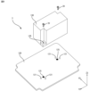
- FIG. 1 is a perspective view of a motor drive device according to this embodiment.
- FIG. 2 is a perspective view showing a state in which the board is removed from the case in FIG. 1.
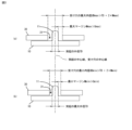
- FIG. 3 is a sectional view showing the protrusion and receiving hole of FIG. 1.
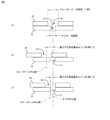
- FIG. 4 is a sectional view showing the screw hole and through hole in FIG. 1.
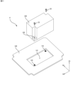
- FIG. 5 is a perspective view schematically showing a case and a board of the motor drive device according to the present embodiment.
- FIG. 6 is a plan view of the second part of FIG. 5.
- FIG. 7 is a perspective view schematically showing a case and a board of a motor drive device according to a second embodiment.
- FIG. 8 is a plan view of the second part of FIG. 7.
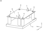
- FIG. 9 is an exploded perspective view of the motor drive device according to the third embodiment.
- 10 is a plan view of the second part of FIG. 9.
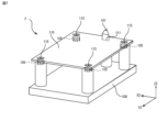
- FIG. 11 is an exploded perspective view of the motor drive device according to the fourth embodiment.
- One feature of the motor drive device is that an alignment structure is directly provided on the components constituting the motor drive device so that the assembly work of the motor drive device can be easily performed. Thereby, the parts can be easily aligned without using a separate alignment jig during the assembly operation, so that the assembly operation of the motor drive device can be performed efficiently.
- a screw is employed as a fastening member that fastens two components that constitute a motor drive device.
- the fastening member is not limited to a screw, and for example, a shaft body such as a bolt or a rivet may be used.
- one of the first component and the second component constituting the motor drive device has a screw hole (corresponding to the first hole) for fastening a screw, and the other has a screw hole for fastening a screw (corresponding to the first hole). It has a through hole (corresponding to the second hole).
- a screw is inserted through a through hole formed in the second component into a screw hole formed in the first component, and is fastened to fix the second component to the first component.
- the screw hole is replaced by a through hole for passing the rivet. In this way, depending on the fastening member used, a screw hole, a through hole, etc. can be employed as the first hole.
- a motor drive device will be described as an example.
- embodiments of the present invention can be broadly applied to various devices and mechanisms having two parts fixed to each other by using shafts such as screws, bolts, rivets, etc.
- FIG. 1 is a perspective view showing a motor drive device according to a first embodiment.
- FIG. 2 is an exploded perspective view of the motor drive device of FIG. 1.
- the motor drive device 1 includes a box-shaped case 10 that is rectangular in plan view with an open top, a case cover 50 that covers the top opening of the case 10, and a motor (not shown). ) on which electronic components (not shown) are mounted.
- the axis parallel to the short side of the case 10 is the X1 axis
- the axis parallel to the long side of the case 10 is the Y1 axis
- the axis parallel to the thickness direction of the case 10 orthogonal to the X1 axis and the Y1 axis is the Z1 axis.
- the direction along the Z1 axis is called the up-down direction.
- the direction in which the board 30 is attached to the case 10 (mounting direction) is parallel to the Z1 axis.
- the case 10 includes a plurality of upwardly protruding protrusions 11, here two protrusions 11, and screw holes 13 into which screws 20 for fixing the board 30 to the case 10 are fastened. and a screw hole 15 into which a screw 40 for fixing the case cover 50 to the case 10 is fastened.
- the screw holes 13 for fastening the board are referred to as the screw holes 13 for the board
- the screw holes 15 for the case cover are referred to as the screw holes 15 for the cover.
- the board screw hole 13 and the cover screw hole 15 are provided with their center lines parallel to the Z1 axis.
- the substrate 30 has two receiving holes 31 that respectively receive the two protrusions 11 provided on the case 10.
- the receiving hole 31 is a through hole that vertically passes through the substrate 30, and is provided with its center line parallel to the Z axis.
- the board 30 has a circular through hole 33 into which a screw used for fixing the board 30 to the case 10 is inserted.
- the protrusion 11 is typically configured to have a cylindrical shape that is longer than the thickness of the substrate 30.
- the outer diameter of the protrusion 11 is desirably larger than the inner diameter of the through hole 33.
- the upper portion of the projection 11 has a tapered shape that becomes thinner toward the tip.
- the entire protrusion 11 may be formed into a cylindrical body that tapers gradually toward the tip.
- the opening of the receiving hole 31 on the back side of the substrate 30 facing the case 10 may be made larger than the opening of the receiving hole 31 on the front side of the substrate 30.
- the receiving hole 31 has an inner diameter UD (UDmax, UDmin) larger than the maximum outer diameter TD of the projection 11.
- the board screw hole 13 of the case 10 may no longer be visible through the through hole 33 of the board 30 after the alignment work.
- the through holes 33 of the board 30 may match the board screw holes 13 of the case 10 in some cases. In such a case, there is no need to adjust the position of the board 30 with respect to the case 10 during the screw tightening operation, so that a decrease in the work efficiency of the screw tightening operation can be suppressed.
- the inner diameter of the receiving hole 31 constituting the alignment structure is designed to achieve both alignment work efficiency and screw tightening work efficiency.
- the upper limit value (maximum inner diameter UDmax) and lower limit value (UDmin) of the inner diameter UD of the receiving hole 31 were determined as follows.
- the upper limit value (maximum inner diameter UDmax) and lower limit value (UDmin) of the inner diameter UD of the receiving hole 31 are determined based not only on the outer diameter TD of the protrusion 11 provided on the case 10 but also on the board screw hole 13 provided on the board 30. Another feature of the first embodiment is that it is defined by the inner diameter ND of the through hole 33 provided in the case 10 and the inner diameter SD of the through hole 33 provided in the case 10.
- the maximum inner diameter UDmax of the receiving hole 31 is set to a value obtained by adding twice the maximum margin Mmax to the outer diameter TD of the protrusion 11.
- the maximum margin Mmax corresponds to the maximum value (maximum allowable shift amount) Smax of the allowable positional shift amount of the through hole 33 with respect to the board screw hole 13.
- the maximum allowable deviation amount Smax can be calculated using the formula ((SD+ND)/2). That is, the maximum inner diameter UDmax of the receiving hole 31 is set to a value that is the sum of the inner diameter SD of the through hole 33 and the inner diameter ND of the board screw hole 13.
- the inner diameter SD of the through hole 33 is larger than the inner diameter ND of the board screw hole 13.
- the maximum allowable displacement amount Smax corresponds to a limit value of the amount of displacement of the through hole 33 with respect to the substrate screw hole 13, which allows an operator to visually recognize a portion of the substrate screw hole 13 through the through hole 33.
- the operator can at least visually recognize the board screw hole 13 through the through hole 33.
- the operator can adjust the board 3 to the case 10 in order to match the through holes 33 with the board screw holes 13. You can quickly figure out in which direction you should move it. Therefore, compared to the case where the board screw hole 13 cannot be visually recognized through the through hole 33, a decrease in the work efficiency of the screw tightening work can be suppressed.
- the minimum inner diameter UDmin of the receiving hole 31 is set to a value obtained by adding twice the minimum margin Mmin to the outer diameter TD of the protrusion 11.
- the minimum margin Mmin corresponds to the minimum value (minimum allowable deviation) Smin of the allowable positional deviation of the through hole 33 with respect to the board screw hole 13.
- the minimum allowable deviation amount Smin can be calculated using the formula ((SD-ND)/2). That is, the minimum inner diameter UDmin of the receiving hole 31 is set to a value that is the sum of the difference between the inner diameter SD of the through hole 33 and the inner diameter ND of the board screw hole 13.
- the minimum allowable deviation amount Smin corresponds to the maximum value of the amount of positional deviation of the through hole 33 with respect to the board screw hole 13, which allows the operator to visually check the entire board screw hole 13 through the through hole 33.
- the operator can see the entire board screw hole 13 through the through hole 33 after the board 30 is aligned with the case 10.
- the screw tightening work of the board 30 to the case 10 can be performed without moving the board 30 and in the same state after alignment. In other words, the operator can perform screw tightening work with the same workability as when the inner diameter UD of the receiving hole 31 matches the outer diameter TD of the protrusion 11.
- the inner diameter UD of the receiving hole 31 is larger than the outer diameter TD of the protrusion 11, it is easier to connect the receiving hole 31 to the protrusion 11 than when the inner diameter UD of the receiving hole 31 matches the outer diameter TD of the protrusion 11. It is easy to insert, and a decrease in work efficiency in positioning the board 30 with respect to the case 10 can be suppressed.
- the inner diameter UD of the receiving hole 31 that constitutes the alignment structure is set to be more than the minimum inner diameter UDmin and less than the maximum inner diameter UDmax, screw tightening work is made easier than when the board screw hole 13 is not visible through the through hole 33.
- a decrease in work efficiency can be suppressed, and a decrease in work efficiency in alignment work can be suppressed compared to the case where the inner diameter UD of the receiving hole 31 matches the outer diameter TD of the protrusion 11. In other words, both the workability of positioning work and the workability of screw tightening work can be achieved.
- the inner diameter UD of 31 may be less than the maximum inner diameter UDmax, and may not be greater than or equal to the minimum inner diameter UDmin.
- the two receiving holes 31 provided in the substrate 30 are arranged at positions that satisfy three arrangement conditions.
- the arrangement conditions will be explained below with reference to FIGS. 5 and 6.
- the arrangement conditions will be explained below with reference to FIGS. 5 and 6.
- the arrangement conditions will be explained below with reference to FIGS. 5 and 6.
- the rectangular plate-shaped second component 90 is aligned with the first component 70.
- the first component 70 schematically represents the case 10
- the second component 90 schematically represents the board 30.
- the protrusion 11 of the case 10 corresponds to the protrusion 71 of the first component 70
- the receiving hole 31 of the substrate 30 corresponds to the receiving hole 91 of the second component 90.
- the center position C1 of the second component 90 corresponds to the center position of the width and length of the second component 90.
- Arrangement Condition 1 The two receiving holes 91 are arranged at positions that are not axisymmetric with respect to an axis Xc1 passing through the center position C1 of the second part 90 and parallel to the short side of the second part 90.
- Arrangement Condition 2 The two receiving holes 91 are arranged at positions that are not axisymmetric with respect to an axis Yc1 that passes through the center position C1 of the second component 90 and is parallel to the long side of the second component 90.
- Arrangement Condition 3 The two receiving holes 91 are arranged at positions that are not symmetrical with respect to the center position C1 of the second component 90.
- the two receiving holes 91 are arranged in positions that satisfy the above three arrangement conditions. That is, when the second component 90 is placed upside down or with the front and back reversed relative to the first component 70, the protrusion 71 of the first component 70 does not pass through the receiving hole 91 of the second component 90 and interferes with the back surface. The second component 90 cannot be fixed to the first component 70 with screws. In other words, it is possible to physically avoid a situation where the second component 90 is attached to the first component 70 in the wrong direction.
- the following effects are achieved. That is, by directly providing the protrusion 11 and the receiving hole 31 that constitute the alignment structure on the case 10 and the substrate 30 that make up the motor drive device 1, the operator can use a separate jig for alignment. The case 10 and the board 30 can be aligned with each other with fewer man-hours, and the efficiency of the assembly work of the motor drive device 1 can be improved.
- the case 10 has the protrusion 11 and the substrate 30 has the receiving hole 31.
- the case 10 may have a receiving hole and the substrate 30 may have a protrusion. Even in such a case, the same effects as in the first embodiment can be achieved.
- the outer diameter of the protrusions be larger than the inner diameter of the screw holes.
- the motor drive device 1 according to the first embodiment has two sets of protrusions and receiving holes as alignment structures.
- the motor drive device 1 according to the first embodiment may have three or more sets of protrusions and receiving holes as the alignment structure.
- the position of the board 30 relative to the case 10 is uniquely determined compared to a configuration with two sets, so there is no risk of attaching the board 30 to the case 10 in the wrong direction. low.
- the protrusion 11 was formed into a cylindrical body, and the receiving hole 31 was formed into a circular shape that matched with the protrusion 11.
- the protrusion 11 is not limited to a cylindrical body, and may be a cylindrical body having an arbitrary cross-sectional shape such as an elliptical cylinder, an elongated cylinder, a polygonal cylinder, or the like.
- the motor drive device 2 according to the second embodiment will be described with reference to FIGS. 7 and 8.
- the first component 100 has one protrusion 101 that projects upward, and a screw hole 105 into which a screw for fixing the second component 110 to the first component 100 is fastened. and has.
- the protrusion 101 has a triangular prism shape.
- the upper portion of the projection 101 has a tapered shape that becomes thinner toward the tip.
- the second component 110 has a triangular receiving hole 111 for receiving the protrusion 101 and a through hole 115 through which a screw for fixing the second component 110 to the first component 100 is passed.
- the center position C of the second component 110 corresponds to the center position of the width and length of the second component 110.
- the inner diameter of the receiving hole 111 is larger than the outer diameter of the protrusion 101, and the maximum value (maximum inner diameter) and minimum value (minimum inner diameter) are determined using the same method as in the first embodiment. It can be calculated using
- the receiving hole 111 be arranged on the axis of symmetry of the second part 110 or at a position other than the center position of the second part 110.
- the receiving hole 111 is located at a position on the axis Xc2 that passes through the center position C2 of the second component 110 and is parallel to the short side of the second component 110, and at a position on the axis Xc2 that passes through the center position C2 of the second component 110 and It is arranged at a position on the axis Yc2 parallel to the long side of the component and at a position other than the center position C2 of the second component 110.
- the second component 110 when aligning the second component 110 with the first component 100 in order to match the through hole 115 of the second component 110 with the screw hole 105 of the first component 100, the second component 110 may be turned upside down. If the orientation is wrong, such as upside down, the receiving hole 111 of the second component 110 cannot be inserted into the protrusion 101 of the first component 100, and the protrusion 101 of the first component 100 will interfere with the second component 110. be able to.
- the second component 110 Since the number of protrusions provided on the first component 100 is one, it is also possible to attach the second component 110 in the wrong direction with respect to the first component 100. However, even if the second component 110 is attached to the first component 100 in the wrong direction, such as upside down or upside down, the second component 110 will clearly shift relative to the first component 100, and the first The through hole 115 of the second component 110 does not match the screw hole 105 of the component 100. Since the operator can easily understand that the second part 110 is aligned in the wrong direction, the situation where the second part 110 is attached to the first part 100 in the wrong direction is avoided. can be avoided.
- the motor drive device 2 according to the second embodiment has one set of protrusions 101 and receiving holes 111 that constitute an alignment structure.
- the motor drive device 1 according to the first embodiment has two sets of protrusions 11 and receiving holes 31 that constitute a positioning structure. Therefore, the second embodiment is superior to the first embodiment in terms of reducing the space in which the alignment structure is provided.
- the durability of the alignment structure specifically, the resistance to the load that the protrusions 11, 101 receive from the substrate 30 during alignment work, the two protrusions 11 can distribute the load. This embodiment is advantageous over the second embodiment with one protrusion 101.
- the alignment structure was composed of a protrusion and a receiving hole, each of which was provided on the two parts to be aligned.
- the configuration of the alignment structure is not limited to this. For example, from the perspective of aligning two parts without using an alignment jig, it is possible to align two parts so that only one part has an alignment structure. Can be configured.
- the motor drive device 3 includes a first component 120 having a plate shape and a second component 130 having a rectangular shape in plan view.
- the second part 130 is aligned with the first part 120 and fixed with the screw 20.
- the first component 120 has a plurality of protrusions 121, four in this case, as an alignment structure for aligning the second component 130 with respect to the first component 120.
- protrusion 121 is configured in a cylindrical shape.
- the four protrusions 121 are arranged on the surface of the first part 120 that the second part 130 contacts, at positions that satisfy the arrangement conditions.
- the outer periphery of the contact surface of the second component 130 that contacts the first component 120 is denoted by 130, and the center position of the second component 130, which is the center of the width and the center of the length of the second component 130, is denoted by the symbol C3. . Further, an axis passing through the center position C3 and parallel to the long side of the contact surface of the second component 130 is indicated by the symbol Xc3, and an axis passing through the center position C3 and parallel to the short side of the contact surface of the second component 130 is indicated by the symbol Xc3. Each is written as Yc3.
- Arrangement condition 1 The four protrusions 121 are arranged along the outer periphery 130a of the contact surface of the second component 130 that contacts the first component 120.
- Arrangement condition 2 The four protrusions 121 are arranged on four sides of the outer periphery 130a of the contact surface of the second component 130 that contacts the first component 120, respectively.
- Arrangement condition 3 An axis Xc3 passing through the center position C3 and parallel to the long side of the contact surface of the second component 130, an axis Yc3 passing through the center position C3 and parallel to the short side of the contact surface of the second component 130.
- At least two protrusions 121 are arranged in at least one of the four sections defined by .
- two protrusions 121 are arranged in each of two sections among the four sections.
- the second part 130 is fitted into the frame defined by the four protrusions 121 of the first part 120, and the second The location of part 130 may be defined. Further, by arranging the four protrusions 121 at positions that satisfy the arrangement conditions 1 and 2, it is possible to stop the aligned second component 130 from moving in the directions along the axis Xc3 and the axis Yc3. In addition, by arranging the four protrusions 121 at positions that satisfy arrangement conditions 1, 2, and 3, rotation of the aligned second part 130 around an axis perpendicular to the surface of the first part 120 is stopped. can do.
- the second component 130 can be aligned with the first component 120 without using an alignment jig, and the second component 130 can be aligned with the first component 120 without using an alignment jig.
- the second component 130 can be fixed to the first component 120 by inserting the screw 20 into the screw hole 125 and the through hole 135 of the second component 130 and tightening the screw 20 .
- the first component 120 which is one of the two components to be aligned, has a plurality of protrusions 121 as an alignment structure.
- the alignment structure that one of the two parts to be aligned has is not limited to a plurality of protrusions.
- the motor drive device 4 according to the fourth embodiment includes a first component 140 having a plate shape and a second component 150 having a rectangular shape in plan view.
- the second component 150 is aligned with the first component 140 and fixed with the screw 20 .
- the first component 140 has a recess 141 that receives the second component 150 as an alignment structure for aligning the second component 150 with respect to the first component 140 .
- the depression 141 has an inner peripheral surface shape that matches the outer peripheral surface shape of the contact surface of the second component 150 that contacts the first component 140 .
- the position of the second part 150 with respect to the first part 140 is defined, and the second part 150 is moved in the X4 direction and the Y4 direction with respect to the first part 140. Movement and rotation around the Z4 axis can be locked.
- the motor drive device 4 it is possible to align the second component 150 with respect to the first component 140 without using an alignment jig, and the second component 150 can be aligned with the first component 140 without using an alignment jig.
- the second component 150 can be fixed to the first component 140 by inserting the screw 20 into the screw hole 145 and the through hole 155 of the second component 150 and tightening the screw 20 .
Landscapes
- Engineering & Computer Science (AREA)
- Microelectronics & Electronic Packaging (AREA)
- Manufacture Of Motors, Generators (AREA)
- Motor Or Generator Frames (AREA)
Abstract
目的は、部品の組立作業を効率的に実施できることにある。本開示の一態様に係るモータ駆動装置1は、第1部品10と第2部品30とを具備する。第1部品に穿設された第1穴13に第2部品に穿設された第2穴33から軸体20が差し込まれることにより第1部品に対して第2部品が固定される。第1部品と第2部品には、第1部品に対して第2部品を位置合わせするための位置合わせ構造11,31が設けられる。位置合わせ構造には、第2穴を通して第1穴を視認できる範囲を限界としてマージンが設けられる。
Description
本発明は、モータを駆動するモータ駆動装置に関する。
モータ駆動装置をはじめとする様々な装置の組み立て作業において、2つの部品をネジ締めにより互いに固定する作業が多く行われている。ネジ締め作業を担当する作業員又はロボットは、一方の部品に形成されたネジ穴に他方の部品に形成されたスルーホールが重なるように、2つの部品を位置合わせし、ずれないように抑えた状態で、ネジを締める。しかしながら、表裏、上下、左右が分かりにくいような部品の位置合わせや軽量な部品の位置合わせでは、作業時間が多くかかってしまう場合がある。また、ネジ締めする際のネジの回転力により部品が回転してしまい、2つの部品を再度位置合わせしなければならない場合がある。
これらに対応するために、2つの部品を位置合わせする治具を別途用意することも考えられる。しかしながら、新たな治具を導入することは、組立作業の工数を増やし、作業性を損なわせる一因となり得る。そのため、部品の組立作業を効率的に実施できることが望まれている。
本開示の一態様に係るモータ駆動装置は、第1部品と第2部品とを具備する。第1部品に穿設された第1穴に第2部品に穿設された第2穴から軸体が差し込まれることにより第1部品に対して第2部品が固定される。第1部品と第2部品には、第1部品に対して第2部品を位置合わせするための位置合わせ構造が設けられる。位置合わせ構造には、第2穴を通して第1穴を視認できる範囲を限界としてマージンが設けられる。
以下、図面を参照しながら本発明の実施形態に係るモータ駆動装置を説明する。以下の説明において、略同一の機能及び構成を有する構成要素については、同一符号を付し、重複説明は必要な場合にのみ行う。
本発明の実施形態に係るモータ駆動装置は、モータ駆動装置の組立作業を容易に行えるように、モータ駆動装置を構成する部品に位置合わせ構造を直接的に設けたことを1つの特徴としている。それにより、組立作業中に位置合わせ用の治具を別途使用することなく、部品同士を容易に位置合わせすることができるため、モータ駆動装置の組立作業を効率的に行うことができる。
本発明の実施形態では、モータ駆動装置を構成する2つの部品を締結する締結部材としてネジを採用する。しかしながら、締結部材はネジに限定されることはなく、例えば、ボルト、リベット等の軸体を採用することができる。
本発明の実施形態では、モータ駆動装置を構成する第1部品、第2部品のうち一方がネジを締結するためのネジ穴(第1穴に対応)を有し、他方はネジを通すためのスルーホール(第2穴に対応)を有する。第1部品に穿設されたネジ穴に第2部品に穿設されたスルーホールからネジが差し込まれ、締結されることにより第1部品に対して第2部品が固定される。しかしながら、締結部材としてリベットを採用した場合、ネジ穴はリベットを通すための貫通孔に代替される。このように、使用する締結部材に応じて、ネジ穴、貫通孔等を第1穴として採用することができる。
本発明の実施形態では、モータ駆動装置を例に説明する。しかしながら、本発明の実施形態は、ネジ、ボルト、リベット等の軸体を用いることにより互いに固定される2つの部品を有する様々な装置、機構に広く適用することができる。
以下、図1,図2を参照して、第1実施形態に係るモータ駆動装置を説明する。図1は、第1実施形態に係るモータ駆動装置を示す斜視図である。図2は、図1のモータ駆動装置の分解斜視図である。図1,図2に示すように、モータ駆動装置1は、上側が開口した平面視で矩形状の箱状のケース10と、ケース10の上側の開口を覆うケースカバー50と、モータ(図示しない)を駆動するための電子部品(図示しない)が実装された基板30と、を有する。
なお、説明の便宜上、直交3軸を以下のように定義する。すなわち、ケース10の短辺に平行な軸をX1軸、ケース10の長辺に平行な軸をY1軸、X1軸及びY1軸に直交するケース10の厚み方向に平行な軸をZ1軸とする。Z1軸に沿った方向は上下方向と称される。ケース10に対して基板30を取り付ける方向(実装方向)はZ1軸と平行である。
図1,図2に示すように、ケース10は、上方向に突出する複数、ここでは2つの突起11と、ケース10に対して基板30を固定するためのネジ20が締結されるネジ穴13と、ケース10に対してケースカバー50を固定するためのネジ40が締結されるネジ穴15とを有する。基板締結用のネジ穴13を基板用ネジ穴13、ケースカバー用のネジ穴15をカバー用ネジ穴15としてそれぞれを区別する。基板用ネジ穴13とカバー用ネジ穴15とは、その中心線がZ1軸と平行となる向きに設けられる。基板30は、ケース10に設けられた2つの突起11をそれぞれ受ける2つの受け穴31を有する。受け穴31は、基板30を上下に貫通する貫通孔であり、その中心線がZ軸と平行になる向きに設けられる。また、基板30は、ケース10に対して基板30を固定するために用いられるネジが挿入される円形状のスルーホール33を有する。
図3,図4を参照して、突起11と受け穴31との詳細を説明する。
図3に示すように、典型的には、突起11は、基板30の厚みよりも長い円柱体に構成される。突起11が基板30のスルーホール33に誤って挿し込まれないように、突起11の外径はスルーホール33の内径より大きいことが望ましい。突起11に受け穴31を通しやすくするために、突起11の上側部分は、先端に向かって細くなるテーパー形状を有する。もちろん、突起11は、それ全体が先端に向かって徐々に細くなる円柱体に構成されていてもよい。同様の効果を奏するために、ケース10に対峙する基板30の裏面側の受け穴31の開口を、基板30の表面側の受け穴31の開口よりも大きくしてもよい。
図3に示すように、典型的には、突起11は、基板30の厚みよりも長い円柱体に構成される。突起11が基板30のスルーホール33に誤って挿し込まれないように、突起11の外径はスルーホール33の内径より大きいことが望ましい。突起11に受け穴31を通しやすくするために、突起11の上側部分は、先端に向かって細くなるテーパー形状を有する。もちろん、突起11は、それ全体が先端に向かって徐々に細くなる円柱体に構成されていてもよい。同様の効果を奏するために、ケース10に対峙する基板30の裏面側の受け穴31の開口を、基板30の表面側の受け穴31の開口よりも大きくしてもよい。
図3(a)、図3(b)に示すように、受け穴31は、突起11の最大外径TDよりも大きい内径UD(UDmax、UDmin)を有する。突起11の外径TDに対して受け穴31の内径UDが大きい程、突起11の外周面と受け穴31の内周面との間の隙間(マージンと称する)が大きくなる。
マージンが大きい程、ケース10に対して基板30を大まかに位置合わせしておくだけで、ケース10の突起11に基板30の受け穴31を通すことができるため、位置合わせ作業の作業効率は向上する。一方、ケース10に対する基板30の位置ズレ量が大きくなるため、位置合わせ作業後に、基板30のスルーホール33を通してケース10の基板用ネジ穴13が視認できなくなってしまう場合がある。ネジ締め作業時に、ケース10の基板用ネジ穴13に基板30のスルーホール33を一致させるために基板30を動かして、ケース10に対して基板30の位置を調整する必要がある。スルーホール33を通して基板用ネジ穴13が視認できないと、基板30をどの向きに動かして良いのか分からないため、スルーホール33を通して基板用ネジ穴13が見えるようになるまで、基板30を色々な方向に動かす必要がある。これは、ネジ締め作業の作業効率を低下させる。
マージンが小さい程、基板30をケース10に対して厳密に位置合わせしなければならないため、位置合わせ作業の作業効率は低下する。一方、ケース10に対する基板30の位置ズレ量は小さくなるため、ケース10の基板用ネジ穴13に基板30のスルーホール33が一致する場合もあり得る。このような場合では、ネジ締め作業時に、ケース10に対する基板30の位置を調整する必要がないため、ネジ締め作業の作業効率の低下を抑えられる。
このように、位置合わせ構造を構成する受け穴31は、その内径が大きすぎるとネジ締め作業の作業効率を低下させ、小さすぎると位置合わせ作業の作業効率を低下させ得る。第1実施形態に係るモータ駆動装置1において、位置合わせ構造を構成する受け穴31の内径は、位置合わせ作業の作業性とネジ締め作業の作業性とを両立するように設計される。具体的には、受け穴31の内径UDの上限値(最大内径UDmax)と下限値(UDmin)とを以下のように定めた。受け穴31の内径UDの上限値(最大内径UDmax)と下限値(UDmin)とを、ケース10に設けられた突起11の外径TDだけではなく、基板30に設けられた基板用ネジ穴13の内径NDとケース10に設けられたスルーホール33の内径SDとにより規定したことも、第1実施形態の1つの特徴である。
図3(a)に示すように、受け穴31の最大内径UDmaxは、突起11の外径TDに最大マージンMmaxの2倍を加算した値に設定される。最大マージンMmaxは、基板用ネジ穴13に対するスルーホール33の位置ズレ許容量の最大値(最大ズレ許容量)Smaxに対応する。図4(b)に示すように、最大ズレ許容量Smaxは、計算式((SD+ND)/2)を用いて算出することができる。つまり、受け穴31の最大内径UDmaxは、スルーホール33の内径SDと基板用ネジ穴13の内径NDとを加算した値に設定される。
なお、図4(a)に示すように、スルーホール33の内径SDは、基板用ネジ穴13の内径NDよりも大きい。最大ズレ許容量Smaxは、作業者がスルーホール33を通して基板用ネジ穴13の一部分を視認できる、基板用ネジ穴13に対するスルーホール33の位置ズレ量の限界値に対応する。
受け穴31の内径UDを最大内径UDmax未満とすることで、作業者は、少なくとも、スルーホール33を通して基板用ネジ穴13を視認することができる。それにより、位置合わせ後に、スルーホール33が基板用ネジ穴13に一致していなくても、作業者は、スルーホール33を基板用ネジ穴13に一致させるために、ケース10に対して基板30をどの向きに動かせばいいのかをすぐに把握することができる。したがって、スルーホール33を通して基板用ネジ穴13を視認することができない場合に比べて、ネジ締め作業の作業効率の低下は抑えられる。
図3(b)に示すように、受け穴31の最小内径UDminは、突起11の外径TDに最小マージンMminの2倍を加算した値に設定される。最小マージンMminは、基板用ネジ穴13に対するスルーホール33の位置ズレ許容量の最小値(最小ズレ許容量)Sminに対応する。図4(c)に示すように、最小ズレ許容量Sminは、計算式((SD―ND)/2)を用いて算出することができる。つまり、受け穴31の最小内径UDminは、スルーホール33の内径SDと基板用ネジ穴13の内径NDとの差分を加算した値に設定される。最小ズレ許容量Sminは、作業者がスルーホール33を通して基板用ネジ穴13の全体を視認できる、基板用ネジ穴13に対するスルーホール33の位置ズレ量に最大値に対応する。
受け穴31の内径UDが最小内径UDminであるとき、ケース10に対して基板30が位置合わせされた後に、作業者はスルーホール33を通して基板用ネジ穴13の全体を視認できるため、作業者は、基板30を動かすことなく、位置合わせされた後のそのままの状態でケース10に対する基板30のネジ締め作業を行うことができる。つまり、作業者は、受け穴31の内径UDが突起11の外径TDに一致するときと同様の作業性で、ネジ締め作業を行うことができる。一方で、受け穴31の内径UDが突起11の外径TDに対して大きいため、受け穴31の内径UDが突起11の外径TDに一致する場合に比べて、受け穴31を突起11に挿し込みやすく、ケース10に対する基板30の位置合わせ作業の作業効率の低下は抑えられる。
したがって、位置合わせ構造を構成する受け穴31の内径UDを、最小内径UDmin以上、最大内径UDmax未満とすることで、スルーホール33を通して基板用ネジ穴13が視認できない場合に比べてネジ締め作業の作業効率の低下を抑えられ、受け穴31の内径UDが突起11の外径TDに一致する場合に比べて位置合わせ作業の作業効率の低下を抑えられる。つまり、位置合わせ作業の作業性とネジ締め作業の作業性とを両立することができる。なお、例えば、位置合わせ作業はロボットが実施し、ネジ締め作業は作業員が実施するような場合などの、ネジ締め作業の作業性のみを考慮するのであれば、位置合わせ構造を構成する受け穴31の内径UDは、最大内径UDmax未満とすればよく、最小内径UDmin以上でなくてもよい。
典型的には、基板30に設けられる2つの受け穴31は、3つの配置条件を満たす位置にそれぞれ配置される。以下、図5、図6を参照して、配置条件を説明する。ここでは、説明を簡単にするために、第1部品70に対して矩形板状の第2部品90を位置合わせするものとする。第1部品70はケース10を模式的に表したものであり、第2部品90が基板30を模式的に表したものである。ケース10の突起11は第1部品70の突起71に対応し、基板30の受け穴31は第2部品90の受け穴91に対応する。第2部品90の中心位置C1は、第2部品90の幅中央且つ長さ中央の位置に対応する。
配置条件1.2つの受け穴91は、第2部品90の中心位置C1を通り第2部品90の短辺に平行な軸Xc1に対して線対称とならない位置にそれぞれ配置される。
配置条件2.2つの受け穴91は、第2部品90の中心位置C1を通り第2部品90の長辺に平行な軸Yc1に対して線対称とならない位置にそれぞれ配置される。
配置条件3.2つの受け穴91は、第2部品90の中心位置C1に対して点対称とならない位置にそれぞれ配置される。
配置条件2.2つの受け穴91は、第2部品90の中心位置C1を通り第2部品90の長辺に平行な軸Yc1に対して線対称とならない位置にそれぞれ配置される。
配置条件3.2つの受け穴91は、第2部品90の中心位置C1に対して点対称とならない位置にそれぞれ配置される。
図6に示すように、2つの受け穴91を上記3つの配置条件を満たす位置に配置することにより以下のような効果を奏する。すなわち、第1部品70に対して第2部品90を上下逆さま又は表裏逆に配置した場合、第1部品70の突起71が第2部品90の受け穴91に通らず、裏面に干渉するため、第1部品70に対して第2部品90をネジにより固定することができない。つまり、第1部品70に対して第2部品90を誤った向きに取り付けてしまう事態を物理的に回避することができる。
第1実施形態に係るモータ駆動装置1によれば、以下の効果を奏する。すなわち、モータ駆動装置1を構成するケース10と基板30とに位置合わせ構造を構成する突起11と受け穴31とをそれぞれ直接設けることにより、作業者は、位置合わせ用の治具を別途用いることなく、少ない作業工数でケース10と基板30との位置合わせを行うことができ、モータ駆動装置1の組立作業の作業効率を向上することができる。
また、位置合わせ構造を構成する受け穴31の大きさの上限値と下限値とを定め、受け穴31の大きさにマージンを持たせることにより、位置合わせ作業の作業性とネジ締め作業の作業性とを両立した。これも、モータ駆動装置1の組立作業の効率向上に寄与するものである。
また、位置合わせ構造を構成する突起11と受け穴31とをケース10と基板30とにそれぞれ二つ設け、基板30に設けられた二つの受け穴31は3つの配置条件を満たす位置に配置した。それにより、ケース10に対して基板30を誤った向きに取りつけてしまう事態を物理的に回避することができる。これも、モータ駆動装置1の組立作業の効率向上に寄与するものである。
第1実施形態では、ケース10が突起11を有し、基板30が受け穴31を有する構成であった。しかしながら、第1実施形態に変形例として、ケース10が受け穴を有し、基板30が突起を有する構成とすることができる。このような場合であっても、第1実施形態と同様の効果を奏する。この場合、基板30が有する突起がケース10のネジ穴13,15に誤って挿し込まれないように、突起の外径はネジ穴の内径よりも大きいことが望ましい。
第1実施形態に係るモータ駆動装置1は、位置合わせ構造として突起と受け穴とを2セット有する。しかしながら、第1実施形態に係るモータ駆動装置1は、位置合わせ構造として突起と受け穴とを3セット以上有してもよい。位置合わせ構造として突起と受け穴とを3セット以上有することにより、2セット有する構成に比べて、ケース10に対する基板30の位置が一意に決まるため、ケース10に対する基板30の取り付け方向を間違えるリスクは低い。
第1実施形態に係るモータ駆動装置1では、突起11は円柱体に構成され、受け穴31は突起11に整合する円形に構成されていた。しかしながら、突起11は円柱体に限定されることはなく、楕円柱体、長円柱体、多角柱体等の任意の横断面形状を有する柱体とすることができる。
以下、図7,図8を参照して、第2実施形態に係るモータ駆動装置2を説明する。ここでは、説明を簡単にするために、第1実施形態と同様に、第1部品100に対して矩形板状の第2部品110を位置合わせするものとする。図7,図8に示すように、第1部品100は上方向に突出する1つの突起101と、第1部品100に対して第2部品110を固定するためのネジが締結されるネジ穴105と、を有する。突起101は、三角柱体に構成される。突起101に受け穴111を通しやすくするために、突起101の上側部分は、先端に向かって細くなるテーパー形状を有する。第2部品110は突起101を受ける三角形状の受け穴111と、第1部品100に対して第2部品110を固定するためのネジが通されるスルーホール115と、を有する。第2部品110の中心位置Cは、第2部品110の幅中央且つ長さ中央の位置に対応する。
第1実施形態と同様に、受け穴111の内径は、突起101の外径に対して大きく、その最大値(最大内径)と最小値(最小内径)とは、第1実施形態と同様の手法を用いて算出することができる。
受け穴111は、第2部品110の対称軸上又は第2部品110の中心位置以外の位置に配置されることが望ましい。具体的には、受け穴111は、第2部品110の中心位置C2を通り第2部品110の短辺に平行な軸Xc2の軸上の位置、第2部品110の中心位置C2を通り第2部品の長辺に平行な軸Yc2の軸上の位置、及び第2部品110の中心位置C2以外の位置に配置される。それにより、第1部品100のネジ穴105に第2部品110のスルーホール115を一致させようと、第2部品110を第1部品100に位置合わせするときに、第2部品110が上下逆さま、表裏逆さま等の誤った向きであれば、第1部品100の突起101に第2部品110の受け穴111を挿し込むことができず、第1部品100の突起101が第2部品110に干渉させることができる。
第1部品100に設けられた突起の数が1つであるため、第1部品100に対して誤った向きで第2部品110を取り付けることも可能である。しかしながら、第1部品100に対して第2部品110が上下逆さま、表裏逆さま等の誤った方向に取り付けられてしまっても、第1部品100に対して第2部品110は明らかにずれ、第1部品100のネジ穴105に第2部品110のスルーホール115は一致しない。作業者は、第2部品110が誤った方向に位置合わせされていることを簡単に把握することができるため、第1部品100に対して第2部品110が誤った方向に取り付けられてしまう事態を回避することができる。
第2実施形態に係るモータ駆動装置2によれば、第1実施形態に係るモータ駆動装置1と同様の効果を奏する。また、第2実施形態に係るモータ駆動装置2は、位置合わせ構造を構成する突起101と受け穴111とを1セット有する。一方、第1実施形態に係るモータ駆動装置1は、位置合わせ構造を構成する突起11―受け穴31を2セット有する。したがって、位置合わせ構造を設けるスペースの狭小化という観点では第2実施形態は第1実施形態に比べて優位である。一方、位置合わせ構造の耐久性、具体的には、位置合わせ作業中に、突起11、101が基板30から受ける負荷に対する耐性という観点では、2本の突起11で負荷を分散できるため、第1実施形態は、1本の突起101を有する第2実施形態に比べて優位である。
第1、第2実施形態では、位置合わせ構造は、突起と受け穴とにより構成され、それぞれが位置合わせ対象の2つの部品にそれぞれ設けられていた。しかしながら、位置合わせ構造の構成はこれに限定されない。例えば、位置合わせ用の治具を使用することなく、2つの部品の位置合わせをするという観点では、位置合わせ対象となる二つの部品のうち一方の部品のみが位置合わせ用の構造を有するように構成することができる。
図9,図10を参照して、第3実施形態に係るモータ駆動装置を説明する。図9に示すように、第3実施形態に係るモータ駆動装置3は、板状の第1部品120と平面視で矩形状の第2部品130とを有する。第1部品120に対して第2部品130が位置合わせされ、ネジ20により固定される。図9に示すように、第1部品120は、第1部品120に対して第2部品130を位置合わせするための位置合わせ構造として、複数、ここでは4つの突起121を有する。典型的には、突起121は円柱体に構成される。4つの突起121は、第2部品130が当接する第1部品120の表面に、配置条件を満たす位置に配置される。
以下、図10を参照して、4つの突起121の配置条件を説明する。なお、第1部品120に当接する第2部品130の当接面の外周を符号130、第2部品130の幅中央且つ長さ中央である第2部品130の中心位置を符号C3でそれぞれ表記する。また、中心位置C3を通り、第2部品130の当接面の長辺に平行な軸を符号Xc3、中心位置C3を通り、第2部品130の当接面の短辺に平行な軸を符号Yc3とそれぞれ表記する。
配置条件1:4つの突起121は、第1部品120に当接する第2部品130の当接面の外周130aに沿ってそれぞれ配置される。
配置条件2:4つの突起121は、第1部品120に当接する第2部品130の当接面の外周130aの4つの辺にそれぞれ配置される。
配置条件2:4つの突起121は、第1部品120に当接する第2部品130の当接面の外周130aの4つの辺にそれぞれ配置される。
配置条件3:中心位置C3を通り、第2部品130の当接面の長辺に平行な軸Xc3、中心位置C3を通り、第2部品130の当接面の短辺に平行な軸Yc3とで規定される4つの区画のうち少なくとも1つの区画に、少なくとも2つの突起121が配置される。なお、図10では、4つの区画のうち2つの区画の各々に2つの突起121が配置されている。
4つの突起121を配置条件1を満たす位置にそれぞれ配置することにより、第1部品120の4つの突起121で規定される枠に第2部品130を嵌め込むことで、第1部品120に対する第2部品130の位置を画定することができる。また、4つの突起121を配置条件1,2を満たす位置にそれぞれ配置することにより、位置合わせされた第2部品130の軸Xc3及び軸Yc3に沿った向きの動きを係止することができる。また、4つの突起121を配置条件1,2、3を満たす位置にそれぞれ配置することで、位置合わせされた第2部品130の、第1部品120の表面に直交する軸周りの回転を係止することができる。
第3実施形態に係るモータ駆動装置3によれば、位置合わせ用の治具を使用することなく、第1部品120に対して第2部品130を位置合わせすることができ、第1部品120のネジ穴125と第2部品130のスルーホール135とにネジ20を挿し込み、締結することで、第1部品120に対して第2部品130を固定することができる。
第3実施形態では、位置合わせ対象の2つの部品のうち一方の部品である第1部品120が位置合わせ構造として、複数の突起121を有する。しかしながら、位置合わせ対象の2つの部品のうち一方の部品が有する位置合わせ構造は複数の突起に限定されない。
図11を参照して、第4実施形態に係るモータ駆動装置4を説明する。図11に示すように、第4実施形態に係るモータ駆動装置4は、板状の第1部品140と平面視で矩形状の第2部品150とを有する。第1部品140に対して第2部品150が位置合わせされ、ネジ20により固定される。図11に示すように、第1部品140は、第1部品140に対して第2部品150を位置合わせするための位置合わせ構造として、第2部品150を受容する窪み141を有する。窪み141は、第1部品140に当接する第2部品150の当接面の外周面形状に整合する内周面形状を有する。
第1部品140の窪み141に第2部品150を嵌め込むことで、第1部品140に対する第2部品150の位置を画定するとともに、第1部品140に対する第2部品150のX4方向及びY4方向への移動及びZ4軸周りの回転を係止することができる。
第4実施形態に係るモータ駆動装置4によれば、位置合わせ用の治具を使用することなく、第1部品140に対して第2部品150を位置合わせすることができ、第1部品140のネジ穴145と第2部品150のスルーホール155とにネジ20を挿し込み、締結することで、第1部品140に対して第2部品150を固定することができる。
本開示の実施形態について詳述したが、本開示は上述した個々の実施形態に限定されるものではない。これらの実施形態は、発明の要旨を逸脱しない範囲で、または、特許請求の範囲に記載された内容とその均等物から導き出される本発明の思想および趣旨を逸脱しない範囲で、種々の追加、置き換え、変更、部分的削除等が可能である。例えば、上述した実施形態において、各動作の順序や各処理の順序は、一例として示したものであり、これらに限定されるものではない。また、上述した実施形態の説明に数値又は数式が用いられている場合も同様である。
1…モータ駆動装置、10…ケース、11…突起、13…基板用ネジ穴、15…カバー用ネジ穴、20,40…ネジ、30…基板、31…受け穴、33…スルーホール、50…ケースカバー、55…スルーホール。
Claims (10)
- 第1部品と、
第2部品とを具備し、
前記第1部品に穿設された第1穴に前記第2部品に穿設された第2穴から軸体が差し込まれることにより前記第1部品に対して前記第2部品が固定され、
前記第1部品と前記第2部品には、前記第1部品に対して前記第2部品を位置合わせするための位置合わせ構造が設けられ、
前記位置合わせ構造には、前記第2穴を通して前記第1穴を視認できる範囲を限界としてマージンが設けられる、モータ駆動装置。 - 前記第1部品又は前記第2部品は、前記位置合わせ構造として少なくとも一つの突起を有し、
前記第2部品又は前記第1部品は、前記位置合わせ構造として少なくとも一つの受け穴を有し、
前記受け穴は、前記第2穴を通して前記第1穴を視認できる内径を有する、請求項1記載のモータ駆動装置。 - 前記受け穴の内径は、前記突起の最大外径に前記第2穴の内径に対する前記第1穴の内径の差分を加えた長さ以上であって、前記突起の最大外径に前記第2穴の内径と前記第1穴の内径と加えた長さ未満である、請求項2記載のモータ駆動装置。
- 前記第1部品は前記突起を有し、前記第2部品は前記受け穴を有し、
前記突起は、前記第2穴の内径よりも大きい外径を有する、請求項2又は3記載のモータ駆動装置。 - 前記第1部品は前記受け穴を有し、前記第2部品は前記突起を有し、
前記突起は、前記第1穴の内径よりも大きい外径を有する、請求項2又は3記載のモータ駆動装置。 - 前記第1部品又は前記第2部品は、前記位置合わせ構造として二つの突起を有し、
前記第2部品又は前記第1部品は、前記位置合わせ構造として二つの受け穴を有し、
前記第1部品又は前記第2部品が有する前記二つの受け穴は、前記第2部品の中心位置に対して点対称の位置関係ではなく、且つ、前記第2部品の中心位置を通る任意の軸に対して線対称の位置関係ではない位置にそれぞれ配置される、請求項2記載のモータ駆動装置。 - 前記第1部品又は前記第2部品は、前記位置合わせ構造として一つの突起を有し、
前記第2部品又は前記第1部品は、前記位置合わせ構造として一つの受け穴を有し、
前記突起は、横断面が非円形状の柱状体に構成され、前記受け穴は前記突起の外径に整合する非円形状の内径を有する、請求項2記載のモータ駆動装置。 - 前記突起は、先端に向かって細くなるテーパー形状を有する、請求項2乃至請求項7のいずれか一項に記載のモータ駆動装置。
- 第1部品と、
第2部品とを具備し、
前記第1部品に穿設された第1穴に前記第2部品に穿設された第2穴から軸体が差し込まれることにより前記第1部品に対して前記第2部品が固定され、
前記第1部品は、前記第1部品に対して前記第2部品を位置合わせするための位置合わせ構造として、前記第2部品の外周面を受ける複数の突起を有する、モータ駆動装置。 - 第1部品と、
第2部品とを具備し、
前記第1部品に穿設された第1穴に前記第2部品に穿設された第2穴から軸体が差し込まれることにより前記第1部品に対して前記第2部品が固定され、
前記第1部品は、前記第1部品に対して前記第2部品を位置合わせするための位置合わせ構造として、前記第1部品は前記第2部品を受容する窪みを有する、モータ駆動装置。
Priority Applications (1)
| Application Number | Priority Date | Filing Date | Title |
|---|---|---|---|
| PCT/JP2022/025561 WO2024003986A1 (ja) | 2022-06-27 | 2022-06-27 | モータ駆動装置 |
Applications Claiming Priority (1)
| Application Number | Priority Date | Filing Date | Title |
|---|---|---|---|
| PCT/JP2022/025561 WO2024003986A1 (ja) | 2022-06-27 | 2022-06-27 | モータ駆動装置 |
Publications (1)
| Publication Number | Publication Date |
|---|---|
| WO2024003986A1 true WO2024003986A1 (ja) | 2024-01-04 |
Family
ID=89382213
Family Applications (1)
| Application Number | Title | Priority Date | Filing Date |
|---|---|---|---|
| PCT/JP2022/025561 WO2024003986A1 (ja) | 2022-06-27 | 2022-06-27 | モータ駆動装置 |
Country Status (1)
| Country | Link |
|---|---|
| WO (1) | WO2024003986A1 (ja) |
Citations (5)
| Publication number | Priority date | Publication date | Assignee | Title |
|---|---|---|---|---|
| JPS62197633U (ja) * | 1986-06-04 | 1987-12-16 | ||
| JP2008283015A (ja) * | 2007-05-11 | 2008-11-20 | Kenwood Corp | 部品の取付構造 |
| JP2015060959A (ja) * | 2013-09-19 | 2015-03-30 | 日立オートモティブシステムズ株式会社 | 電子制御装置 |
| JP2019134648A (ja) * | 2018-02-02 | 2019-08-08 | 株式会社豊田自動織機 | インバータ |
| JP2020195274A (ja) * | 2019-05-30 | 2020-12-03 | 株式会社豊田自動織機 | 半導体装置 |
-
2022
- 2022-06-27 WO PCT/JP2022/025561 patent/WO2024003986A1/ja unknown
Patent Citations (5)
| Publication number | Priority date | Publication date | Assignee | Title |
|---|---|---|---|---|
| JPS62197633U (ja) * | 1986-06-04 | 1987-12-16 | ||
| JP2008283015A (ja) * | 2007-05-11 | 2008-11-20 | Kenwood Corp | 部品の取付構造 |
| JP2015060959A (ja) * | 2013-09-19 | 2015-03-30 | 日立オートモティブシステムズ株式会社 | 電子制御装置 |
| JP2019134648A (ja) * | 2018-02-02 | 2019-08-08 | 株式会社豊田自動織機 | インバータ |
| JP2020195274A (ja) * | 2019-05-30 | 2020-12-03 | 株式会社豊田自動織機 | 半導体装置 |
Similar Documents
| Publication | Publication Date | Title |
|---|---|---|
| JP2011509387A (ja) | 公差累積補正のための装置及び方法 | |
| JP6279307B2 (ja) | バッテリー端子ストッパ、及び、バッテリー端子ユニット | |
| WO2024003986A1 (ja) | モータ駆動装置 | |
| EP1832761A1 (en) | Self-retaining bolt | |
| JP4332678B2 (ja) | 部品取付構造 | |
| JP2021166423A (ja) | モータ | |
| JP2003314513A (ja) | 連結具 | |
| WO2020203442A1 (ja) | 電気機器ユニットの連結構造および電気機器 | |
| US20210378125A1 (en) | Foolproof frame assembly and server chassis including the same | |
| JP2015172392A (ja) | 偏心カム式支持位置調整装置 | |
| JP7247755B2 (ja) | 半導体装置 | |
| JP3978541B2 (ja) | エンジンのシリンダヘッドカバー及びその組立方法 | |
| JP6193015B2 (ja) | バルブ組立て用治具 | |
| JP7144990B2 (ja) | 締結部材保護具 | |
| WO2011118426A1 (ja) | 車両用ドアミラー | |
| JP7361639B2 (ja) | 位置決め治具 | |
| JP6808707B2 (ja) | コネクタユニットおよびコネクタ構造 | |
| JP7165284B2 (ja) | ワーク把持機構 | |
| US20200398395A1 (en) | Fixing member and spindle device | |
| US11828326B2 (en) | Control system using a control cable, an adapter element for such a system, and a control cable having such an adapter element | |
| WO2010006519A1 (zh) | 直流无刷电机霍尔装置装配结构 | |
| JP2012097845A (ja) | ウェルドナットの取付け構造 | |
| JP2015203446A (ja) | ヒンジの位置決め構造 | |
| JP6749639B2 (ja) | リニアブレーキ装置 | |
| JP2019022405A (ja) | 電動アクチュエータ |
Legal Events
| Date | Code | Title | Description |
|---|---|---|---|
| 121 | Ep: the epo has been informed by wipo that ep was designated in this application |
Ref document number: 22949265 Country of ref document: EP Kind code of ref document: A1 |