WO2023286687A1 - 集電板およびこれを用いた蓄電装置 - Google Patents
集電板およびこれを用いた蓄電装置 Download PDFInfo
- Publication number
- WO2023286687A1 WO2023286687A1 PCT/JP2022/026934 JP2022026934W WO2023286687A1 WO 2023286687 A1 WO2023286687 A1 WO 2023286687A1 JP 2022026934 W JP2022026934 W JP 2022026934W WO 2023286687 A1 WO2023286687 A1 WO 2023286687A1
- Authority
- WO
- WIPO (PCT)
- Prior art keywords
- current collector
- collector plate
- main surface
- portions
- case
- Prior art date
- Legal status (The legal status is an assumption and is not a legal conclusion. Google has not performed a legal analysis and makes no representation as to the accuracy of the status listed.)
- Ceased
Links
Images


Classifications
-
- H—ELECTRICITY
- H01—ELECTRIC ELEMENTS
- H01M—PROCESSES OR MEANS, e.g. BATTERIES, FOR THE DIRECT CONVERSION OF CHEMICAL ENERGY INTO ELECTRICAL ENERGY
- H01M50/00—Constructional details or processes of manufacture of the non-active parts of electrochemical cells other than fuel cells, e.g. hybrid cells
- H01M50/50—Current conducting connections for cells or batteries
- H01M50/531—Electrode connections inside a battery casing
- H01M50/533—Electrode connections inside a battery casing characterised by the shape of the leads or tabs
-
- H—ELECTRICITY
- H01—ELECTRIC ELEMENTS
- H01M—PROCESSES OR MEANS, e.g. BATTERIES, FOR THE DIRECT CONVERSION OF CHEMICAL ENERGY INTO ELECTRICAL ENERGY
- H01M10/00—Secondary cells; Manufacture thereof
- H01M10/05—Accumulators with non-aqueous electrolyte
- H01M10/058—Construction or manufacture
- H01M10/0587—Construction or manufacture of accumulators having only wound construction elements, i.e. wound positive electrodes, wound negative electrodes and wound separators
-
- H—ELECTRICITY
- H01—ELECTRIC ELEMENTS
- H01G—CAPACITORS; CAPACITORS, RECTIFIERS, DETECTORS, SWITCHING DEVICES, LIGHT-SENSITIVE OR TEMPERATURE-SENSITIVE DEVICES OF THE ELECTROLYTIC TYPE
- H01G11/00—Hybrid capacitors, i.e. capacitors having different positive and negative electrodes; Electric double-layer [EDL] capacitors; Processes for the manufacture thereof or of parts thereof
- H01G11/66—Current collectors
- H01G11/70—Current collectors characterised by their structure
-
- H—ELECTRICITY
- H01—ELECTRIC ELEMENTS
- H01G—CAPACITORS; CAPACITORS, RECTIFIERS, DETECTORS, SWITCHING DEVICES, LIGHT-SENSITIVE OR TEMPERATURE-SENSITIVE DEVICES OF THE ELECTROLYTIC TYPE
- H01G11/00—Hybrid capacitors, i.e. capacitors having different positive and negative electrodes; Electric double-layer [EDL] capacitors; Processes for the manufacture thereof or of parts thereof
- H01G11/78—Cases; Housings; Encapsulations; Mountings
- H01G11/82—Fixing or assembling a capacitive element in a housing, e.g. mounting electrodes, current collectors or terminals in containers or encapsulations
-
- H—ELECTRICITY
- H01—ELECTRIC ELEMENTS
- H01M—PROCESSES OR MEANS, e.g. BATTERIES, FOR THE DIRECT CONVERSION OF CHEMICAL ENERGY INTO ELECTRICAL ENERGY
- H01M10/00—Secondary cells; Manufacture thereof
- H01M10/04—Construction or manufacture in general
- H01M10/0431—Cells with wound or folded electrodes
-
- H—ELECTRICITY
- H01—ELECTRIC ELEMENTS
- H01M—PROCESSES OR MEANS, e.g. BATTERIES, FOR THE DIRECT CONVERSION OF CHEMICAL ENERGY INTO ELECTRICAL ENERGY
- H01M50/00—Constructional details or processes of manufacture of the non-active parts of electrochemical cells other than fuel cells, e.g. hybrid cells
- H01M50/10—Primary casings; Jackets or wrappings
- H01M50/102—Primary casings; Jackets or wrappings characterised by their shape or physical structure
- H01M50/103—Primary casings; Jackets or wrappings characterised by their shape or physical structure prismatic or rectangular
-
- H—ELECTRICITY
- H01—ELECTRIC ELEMENTS
- H01M—PROCESSES OR MEANS, e.g. BATTERIES, FOR THE DIRECT CONVERSION OF CHEMICAL ENERGY INTO ELECTRICAL ENERGY
- H01M50/00—Constructional details or processes of manufacture of the non-active parts of electrochemical cells other than fuel cells, e.g. hybrid cells
- H01M50/10—Primary casings; Jackets or wrappings
- H01M50/102—Primary casings; Jackets or wrappings characterised by their shape or physical structure
- H01M50/107—Primary casings; Jackets or wrappings characterised by their shape or physical structure having curved cross-section, e.g. round or elliptic
-
- H—ELECTRICITY
- H01—ELECTRIC ELEMENTS
- H01M—PROCESSES OR MEANS, e.g. BATTERIES, FOR THE DIRECT CONVERSION OF CHEMICAL ENERGY INTO ELECTRICAL ENERGY
- H01M50/00—Constructional details or processes of manufacture of the non-active parts of electrochemical cells other than fuel cells, e.g. hybrid cells
- H01M50/30—Arrangements for facilitating escape of gases
- H01M50/342—Non-re-sealable arrangements
-
- H—ELECTRICITY
- H01—ELECTRIC ELEMENTS
- H01M—PROCESSES OR MEANS, e.g. BATTERIES, FOR THE DIRECT CONVERSION OF CHEMICAL ENERGY INTO ELECTRICAL ENERGY
- H01M50/00—Constructional details or processes of manufacture of the non-active parts of electrochemical cells other than fuel cells, e.g. hybrid cells
- H01M50/30—Arrangements for facilitating escape of gases
- H01M50/342—Non-re-sealable arrangements
- H01M50/3425—Non-re-sealable arrangements in the form of rupturable membranes or weakened parts, e.g. pierced with the aid of a sharp member
-
- H—ELECTRICITY
- H01—ELECTRIC ELEMENTS
- H01M—PROCESSES OR MEANS, e.g. BATTERIES, FOR THE DIRECT CONVERSION OF CHEMICAL ENERGY INTO ELECTRICAL ENERGY
- H01M50/00—Constructional details or processes of manufacture of the non-active parts of electrochemical cells other than fuel cells, e.g. hybrid cells
- H01M50/50—Current conducting connections for cells or batteries
- H01M50/531—Electrode connections inside a battery casing
- H01M50/534—Electrode connections inside a battery casing characterised by the material of the leads or tabs
-
- H—ELECTRICITY
- H01—ELECTRIC ELEMENTS
- H01M—PROCESSES OR MEANS, e.g. BATTERIES, FOR THE DIRECT CONVERSION OF CHEMICAL ENERGY INTO ELECTRICAL ENERGY
- H01M50/00—Constructional details or processes of manufacture of the non-active parts of electrochemical cells other than fuel cells, e.g. hybrid cells
- H01M50/50—Current conducting connections for cells or batteries
- H01M50/531—Electrode connections inside a battery casing
- H01M50/536—Electrode connections inside a battery casing characterised by the method of fixing the leads to the electrodes, e.g. by welding
-
- H—ELECTRICITY
- H01—ELECTRIC ELEMENTS
- H01M—PROCESSES OR MEANS, e.g. BATTERIES, FOR THE DIRECT CONVERSION OF CHEMICAL ENERGY INTO ELECTRICAL ENERGY
- H01M50/00—Constructional details or processes of manufacture of the non-active parts of electrochemical cells other than fuel cells, e.g. hybrid cells
- H01M50/50—Current conducting connections for cells or batteries
- H01M50/531—Electrode connections inside a battery casing
- H01M50/538—Connection of several leads or tabs of wound or folded electrode stacks
-
- H—ELECTRICITY
- H01—ELECTRIC ELEMENTS
- H01M—PROCESSES OR MEANS, e.g. BATTERIES, FOR THE DIRECT CONVERSION OF CHEMICAL ENERGY INTO ELECTRICAL ENERGY
- H01M50/00—Constructional details or processes of manufacture of the non-active parts of electrochemical cells other than fuel cells, e.g. hybrid cells
- H01M50/50—Current conducting connections for cells or batteries
- H01M50/543—Terminals
- H01M50/552—Terminals characterised by their shape
- H01M50/559—Terminals adapted for cells having curved cross-section, e.g. round, elliptic or button cells
-
- H—ELECTRICITY
- H01—ELECTRIC ELEMENTS
- H01G—CAPACITORS; CAPACITORS, RECTIFIERS, DETECTORS, SWITCHING DEVICES, LIGHT-SENSITIVE OR TEMPERATURE-SENSITIVE DEVICES OF THE ELECTROLYTIC TYPE
- H01G11/00—Hybrid capacitors, i.e. capacitors having different positive and negative electrodes; Electric double-layer [EDL] capacitors; Processes for the manufacture thereof or of parts thereof
- H01G11/74—Terminals, e.g. extensions of current collectors
-
- H—ELECTRICITY
- H01—ELECTRIC ELEMENTS
- H01G—CAPACITORS; CAPACITORS, RECTIFIERS, DETECTORS, SWITCHING DEVICES, LIGHT-SENSITIVE OR TEMPERATURE-SENSITIVE DEVICES OF THE ELECTROLYTIC TYPE
- H01G11/00—Hybrid capacitors, i.e. capacitors having different positive and negative electrodes; Electric double-layer [EDL] capacitors; Processes for the manufacture thereof or of parts thereof
- H01G11/78—Cases; Housings; Encapsulations; Mountings
-
- Y—GENERAL TAGGING OF NEW TECHNOLOGICAL DEVELOPMENTS; GENERAL TAGGING OF CROSS-SECTIONAL TECHNOLOGIES SPANNING OVER SEVERAL SECTIONS OF THE IPC; TECHNICAL SUBJECTS COVERED BY FORMER USPC CROSS-REFERENCE ART COLLECTIONS [XRACs] AND DIGESTS
- Y02—TECHNOLOGIES OR APPLICATIONS FOR MITIGATION OR ADAPTATION AGAINST CLIMATE CHANGE
- Y02E—REDUCTION OF GREENHOUSE GAS [GHG] EMISSIONS, RELATED TO ENERGY GENERATION, TRANSMISSION OR DISTRIBUTION
- Y02E60/00—Enabling technologies; Technologies with a potential or indirect contribution to GHG emissions mitigation
- Y02E60/10—Energy storage using batteries
-
- Y—GENERAL TAGGING OF NEW TECHNOLOGICAL DEVELOPMENTS; GENERAL TAGGING OF CROSS-SECTIONAL TECHNOLOGIES SPANNING OVER SEVERAL SECTIONS OF THE IPC; TECHNICAL SUBJECTS COVERED BY FORMER USPC CROSS-REFERENCE ART COLLECTIONS [XRACs] AND DIGESTS
- Y02—TECHNOLOGIES OR APPLICATIONS FOR MITIGATION OR ADAPTATION AGAINST CLIMATE CHANGE
- Y02P—CLIMATE CHANGE MITIGATION TECHNOLOGIES IN THE PRODUCTION OR PROCESSING OF GOODS
- Y02P70/00—Climate change mitigation technologies in the production process for final industrial or consumer products
- Y02P70/50—Manufacturing or production processes characterised by the final manufactured product
Definitions
- Patent Document 1 discloses a case, an anode plate, a cathode plate, and a separator interposed between the anode plate and the cathode plate. an attached electrode assembly, a cap assembly enclosing the case, and an anode current collector and a cathode current collector electrically connected to the anode plate and the cathode plate of the electrode assembly, respectively;
- a secondary battery has been proposed in which at least one of the anode current collector plate and the cathode current collector plate includes a plate-like main body and a contact portion protruding from the main body and in contact with the corresponding anode plate or cathode plate.
- One aspect of the present disclosure is a plate having a first main surface and a second main surface opposite to the first main surface, a first portion in the center, and a first portion extending in a first direction away from the first portion. a plurality of second portions; a plurality of third portions extending from a portion of the second portion spaced apart from the first portion and protruding in a second direction intersecting the first direction; and a current collector plate in which a gap is formed between a third portion extending from one of the second portions and a third portion extending from the other of the second portions.
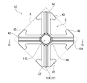
- FIG. 2 is a top view showing the appearance of a current collector plate according to an embodiment of the present disclosure
- 1B is a cross-sectional view in the X 1 -X 2 direction of FIG. 1A
- FIG. 1 is a perspective view showing the appearance of a current collector plate according to an embodiment of the present disclosure
- FIG. FIG. 4 is a top view showing another example of the current collector plate according to the embodiment of the present disclosure
- FIG. 4 is a top view showing another example of the current collector plate according to the embodiment of the present disclosure
- 1 is a side view showing the appearance of a battery according to an embodiment of the present disclosure
- a current collector is provided in a power storage device such as a battery (for example, a secondary battery).
- a power storage device includes, for example, a case having a tubular portion and a bottom portion that closes one end of the tubular portion.
- a columnar wound body in which a positive electrode and a negative electrode are wound with a separator interposed is housed in a case so that one end surface of the wound body faces the bottom.
- the other end of the tubular portion of the case has an opening.
- the opening of the case is closed and kept airtight while the wound body is accommodated therein.
- the sealing method for sealing the opening of the case is not particularly limited, and a known method can be used.
- the third portion extends from a portion of the second portion spaced apart from the first portion, and extends (for example, along the circumferential direction of the cylindrical portion) so as to protrude in a second direction that intersects the first direction. .
- a third portion extending from one second portion and a third portion extending from the other second portion are separated from each other to form a gap.
- a radially extending gap is interposed between the third portions and between the second portions. This gap functions as an exhaust path through which generated gas is exhausted when abnormal heat is generated.
- the current collector plate having the second portion and the third portion the gas generated at the time of abnormal heat generation can be exhausted at high speed, and the abnormal heat generation state can be immediately stopped.
- the third portion has the effect of holding the wound body inside the case when the gas is exhausted. This is because the provision of the third portion increases the rigidity of the portion of the current collector plate where the third portion is provided.
- the third portions can more actively bite into the current collector exposed portion of the wound body to which the third portions are electrically connected. can be done. By digging in more, the current collector plate can be more firmly fixed to the current collector exposed portion, and the electrical resistance between the third portion and the current collector exposed portion can be reduced.
- the explosion-proof mechanism provided at the bottom of the case be provided in a region that is located on the inner peripheral side of the third portion and does not overlap with the third portion so as not to interfere with gas exhaust.
- the third portion protrude in the second direction intersecting with the radial direction on the outer peripheral side of the region where the explosion-proof mechanism is arranged.
- the explosion-proof mechanism is inside the outermost circumference of the third portion.
- at least part of the third portion may be arranged outside the region in which the explosion-proof mechanism is formed on the bottom.
- a portion extending in the radial direction may be formed in the second portion while protruding toward the second main surface.
- the portion protruding toward the second principal surface is a recess when viewed from the first principal surface, and the recess extends radially to form a groove.
- the current collector When the current collector is arranged between the bottom and the roll, the current collector can preferentially contact the roll in this groove. Therefore, electrical connection can be made between the current collector plate and one electrode of the wound body through the groove. Electrical connection can be achieved, for example, by welding one electrode to the current collector plate in the groove while the current collector plate is pressed against the winding body so that the groove contacts the one electrode.
- the protruding portion is recessed when viewed from the first main surface side, it is possible to prevent the protruding portion from becoming thicker.
- the current collector plate may further have plated layers laminated on the first main surface and the second main surface. At this time, the thickness of the plated layer laminated on the first main surface side may be thinner than the thickness of the plated layer laminated on the second main surface side.
- the plating layer on the first main surface side is prevented from reflecting the laser when welding is performed by irradiating the laser from the outside of the case.
- the material (underlying layer) of the current collector plate include iron, stainless steel, copper, etc., when connecting to the negative electrode, and aluminum, iron, etc., when connecting to the positive electrode. Nickel etc. are mentioned as a plating layer. This plating layer is not essential in the current collector plate of the present disclosure.
- a power storage device includes a columnar wound body in which a positive electrode and a negative electrode are wound with a separator interposed therebetween, a case that accommodates the wound body, and the current collector plate.
- the case has a tubular portion and a bottom portion that closes one end of the tubular portion. At least a first portion of the current collector plate is electrically connected to the bottom of the case on the first main surface side, and at least a second portion of the current collector plate is on the second main surface side of the winding body. It is electrically connected to either one of the positive electrode and the negative electrode on the end surface facing the main surface.
- the method of electrical connection between the other electrode of the positive electrode and the negative electrode of the wound body and the terminal plate is not particularly limited.
- One end of the internal lead is attached to the other electrode, and the other end of the internal lead is connected to the terminal plate. It may be carried out through a current collector plate.
- the first current collector plate is a current collector plate having a first portion, a second portion and a third portion, as described above.
- the second current collector plate having the first portion, the second portion, and the third portion By using the second current collector plate having the first portion, the second portion, and the third portion, it is possible to rapidly discharge gas from the terminal plate side in addition to discharging gas from the bottom of the case when abnormal heat is generated. can. As a result, it becomes easier to stop the abnormal heat generation immediately.
- the size of the power storage device is not particularly limited, and for example, the outer diameter of the case may be 18 mm or more, 21 mm or more, or 46 mm or more.
- the larger the outer diameter of the battery the higher the output, but the greater the amount of gas generated at the time of abnormal heat generation. Therefore, it is effective to use the current collector plate of the present disclosure.
- the ratio of the area of the area where the explosion-proof mechanism (for example, explosion-proof valve) is formed on the bottom to the area of the bottom of the case may be 90% or less, or 80% or less. good too.
- the current collector plate of the present disclosure can be employed in the structure of any power storage device, regardless of whether it is a primary battery or a secondary battery, and regardless of the configuration of the positive electrode and the negative electrode.
- a current collector plate according to an embodiment of the present disclosure will be specifically described below with reference to the drawings, taking as an example a case where the current collector plate is used in a lithium-ion secondary battery, which is an example of a power storage device.
- FIG. 1A, 1B, and 2 are diagrams illustrating an example of a configuration of a current collector plate according to an embodiment of the present disclosure.
- FIG. 1A is a top view showing the appearance of a current collecting plate
- FIG. 1B is a cross-sectional view taken along the X 1 -X 2 direction in FIG. 1A.
- FIG. 2 is a perspective view of the current collector plate viewed from the first main surface side (the bottom side of the case).
- the current collector plate 40 includes a central first portion 41 , a plurality of second portions 42 radially extending along the first direction (radial direction) away from the first portion 41 , and each of the second portions 42 . It has a plurality of third portions 43 that extend from locations spaced apart from the first portion 41 and protrude in a second direction (circumferential direction) intersecting the first direction. In the adjacent second portions 42, the third portion extending from one second portion to the other second portion is spaced apart from the third portion extending from the other second portion to the one second portion. there is That is, a gap is formed between the third portion extending from the one second portion and the third portion extending from the other second portion.
- the current collector plate 40 has a plate shape having a first main surface S1 and a second main surface S2 opposite to the first main surface S1 (rear surface).
- the current collecting plate 40 is, for example, a metal plate, which is punched into a predetermined shape and then processed into a shape having unevenness by press molding.
- the current collector plate 40 is arranged in the battery, it is arranged between the case bottom and the winding body such that the first principal surface S1 faces the case bottom and the second principal face S2 faces the winding body. be done.
- FIG. 2 shows the appearance of the current collector plate viewed from the first main surface S1 side (the bottom side of the case).
- the first portion 41 has a protruding surface 41S protruding toward the first main surface S1.
- the projecting surface 41S contacts the bottom surface of the battery case, and the current collecting plate 40 and the case are electrically connected.
- the second portion 42 has a projecting surface 42S that projects toward the second main surface S2.
- the projecting surface extends along the direction in which the second portion 42 extends, and when viewed from the first main surface side, a groove portion 42A extending along the direction in which the second portion 42 extends is formed.
- the collector plate 40 and one electrode of the wound body are electrically connected.
- a gap G is interposed between the adjacent second portions 42 and between the adjacent third portions 43 continuously from the adjacent second portions 42 . Via this gap G, the gas generated at the time of abnormal heat generation can be released efficiently. Since the adjacent third portions 43 extend from the tips of the second portions 42 so as to approach each other, the width of the gap G between the second portions 42 is greater than the width of the gap G between the third portions 43. also widens.
- the third portion 43 extends so as to protrude from the second portion 42 on both sides in a direction substantially perpendicular to the direction in which the second portion 42 extends, thereby preventing the wound body from jumping out of the case. It has the effect of holding down and fixing.
- the current collector plate 40 in the current collector plate 40, four second portions 42 radially extend from the first portion 41 so as to form an angle of 90° with each other. Further, the third portion 43 extends from the tip of the second portion 42 while retreating toward the first portion 41 so that the second portion and the overall shape of the third portion 43 that is continuous with the second portion forms an arrowhead. ing. As a result, a portion of the contour of each of the plurality of third portions 43 touches the predetermined square R, as can be seen from FIG. 1A. As a result, the overall contour shape of the current collector plate 40 is a shape inscribed in a square.
- both the effect of fixing the wound body and the effect of efficiently exhausting gas can be achieved in a high state.
- the current collector plate 40 has a contour shape inscribed in a square, residue is reduced when the current collector plate 40 is manufactured by punching a metal plate, and production efficiency is improved.
- a current collector plate 40A shown in FIG. 3A is an example in which the third portion 43 is arranged to extend in an arc shape from the tip of the second portion 42 .
- the arcuate third portion 43 can be arranged to extend along the inner peripheral wall of the battery case when arranged inside the battery.
- FIG. 4 is a side view showing the appearance of the battery 200 according to this embodiment in which the current collector plate 40 is arranged.
- FIG. 5 is a schematic diagram showing a partially cutaway case 210 showing a state where the case 210 and the current collector plate 40 are arranged.
- FIG. 6 is a longitudinal sectional view showing the internal structure of battery 200 on the bottom side of case 210 .
- the negative electrode 20 is in the form of a long sheet, and includes a negative electrode current collector and a negative electrode active material layer carried thereon.
- the negative electrode active material layer is formed on both sides of the negative electrode current collector.
- a negative electrode current collector exposed portion 21x having no negative electrode active material layer is formed at one end along the longitudinal direction of the negative electrode current collector.
- the current collector plate 40 is in contact with the negative electrode current collector exposed portion 21x in a groove portion 42A formed in the second portion 42 thereof and protruding toward the second main surface side opposite to the first main surface S1. .
- the current collector plate 40 and the negative electrode current collector exposed portion 21x are welded. Therefore, the case 210 functions as an external negative terminal.
- a thin portion 210X is provided at the bottom of the case 210.
- the case 210 breaks at the thin portion 210X, and the gas is exhausted.
- the third portion 43 of the current collector plate 40 serves to fix the wound body 100 within the case 210 as the gas is exhausted.
- the third portion 43 also extends on the outer peripheral side from the location where the thin portion 210X is provided so as not to hinder gas exhaust.
- the inner surface of the bottom of the case 210 is not flat, and has an annular recess 210A on the outer peripheral side.
- the tip of the third portion 43 of the current collector plate 40 may protrude toward the first main surface S1 so as to engage with the recess 210A.
- the protruding portion of the third portion 43 comes into contact with the case 210, so that the electrical connection between the current collector plate 40 and the case 210 is improved. can enhance the effect of being fixed.
- a through-hole may be provided in the first portion 41 in order to facilitate injection of the electrolytic solution during manufacturing and to further facilitate gas discharge during abnormal heat generation. Since the first portion 41 faces the hollow region of the core portion of the wound body 100, the gas from the hollow region is discharged by providing a through hole in the first portion 41 and forming a gas exhaust path. becomes easier.
- FIG. 7 shows an example of a current collector plate 40C in which a protruding portion 43A protruding toward the first main surface S1 is provided at the tip of the third portion 43, and a through hole 41H is provided in the first portion 41.
- the third portion 43 extending in the second direction is bent at the tip to form a projecting portion 43A projecting toward the first main surface S1.
- the projecting portion 43A is not limited to this configuration, and for example, the thickness of the third portion 43 may be increased at the distal end portion to project toward the first main surface S1.
- the through hole 41H is provided at the center of the projecting surface 41S of the first portion 41.
- the present invention is not limited to this. may be set to However, in that case, the through-hole 41H should be located at a position not facing the groove 42A in the circumferential direction (for example, , at a position facing the gap G).
- FIGS. 8A and 8B show another example of a current collector plate having through holes 41H provided in the first portion 41.
- FIG. 8A and 8B are enlarged top views showing the periphery of the first portion of the current collector plate.
- the through hole 41H is provided inside the welding position 41X with the case bottom.
- the through hole 41H may be cross-shaped as shown in FIG. 8A, and its shape is not particularly limited. Also, a plurality of through holes 41H may be arranged as shown in FIG. 8B.
- the material forming the current collector plate 40 is determined according to the material forming the positive electrode and the negative electrode.
- the material of the current collector plate 40 when used as a negative electrode current collector plate for a lithium ion secondary battery, is, for example, copper, copper alloy, nickel, stainless steel, or the like.
- the material of the negative electrode current collector may be the same as the material of the negative electrode current collector 21 .
- the material of the collector plate 40 when used as a positive collector plate for a lithium-ion secondary battery, is, for example, aluminum, an aluminum alloy, titanium, stainless steel, or the like.
- the material of the positive electrode current collector may be the same as the material of the positive electrode current collector.
- the temperature of the second portion rises more when the outside of the second portion is welded than when the inside of the second portion is welded.
- the outer side of the second portion 42 is easily melted during welding. Then, in the radial direction, the reliability of welding of the joint between the outside of the second portion 42 of the current collector plate 40 and one of the positive electrode and the negative electrode can be improved.
- the current collection path of the wound body 100 in the winding direction is greater in the outer portion than in the inner portion of the wound body.
- the distance between the connection points with the two parts is increased. Therefore, the current collection path in the winding direction becomes longer on the outer side of the wound body 100 .
- the current collection path in the winding body tends to be longer than when the welding failure occurs on the inside, and the current collection resistance of the power storage device 200 tends to deteriorate. . Therefore, by increasing the welding reliability outside the second portion 42 of the current collector plate 40 in the radial direction, deterioration of current collection resistance when current is collected from the wound body 100 to the current collector plate 40 can be prevented. can be suppressed.
- a sheet-like metal material is used for the positive electrode current collector.
- the sheet-shaped metal material may be a metal foil, a metal porous body, an etched metal, or the like. Aluminum, an aluminum alloy, nickel, titanium, etc. can be used as the metal material.
- the thickness of the positive electrode current collector is, for example, 10 ⁇ m to 100 ⁇ m.
- the negative electrode current collector A sheet-like metal material is used for the negative electrode current collector.
- the sheet-shaped metal material may be a metal foil, a metal porous body, an etched metal, or the like.
- metal materials copper, copper alloys, nickel, stainless steel, and the like can be used.
- the thickness of the negative electrode current collector is, for example, 10 ⁇ m to 100 ⁇ m.
- the negative electrode active material layer contains, for example, a negative electrode active material, a conductive agent, and a binder.
- the negative electrode active material layer is obtained, for example, by applying a negative electrode mixture slurry containing a negative electrode active material, a conductive material, and a binder on both sides of a negative electrode current collector, drying the coating film, and then rolling.
- a negative electrode active material is a material that absorbs and releases lithium ions. Examples of negative electrode active materials include carbon materials, metal compounds, alloys, and ceramic materials.
- separator for example, a microporous film made of resin such as polyolefin, woven fabric, non-woven fabric, or the like can be used.
- the thickness of the separator is, for example, 10-300 ⁇ m, preferably 10-40 ⁇ m.
- Non-aqueous electrolyte has lithium ion conductivity and contains a lithium salt and a non-aqueous solvent that dissolves the lithium salt.
- the current collector plate according to the present disclosure can be used to realize a high-output power storage device, and is therefore suitable for in-vehicle use, for example.
Landscapes
- Chemical & Material Sciences (AREA)
- Chemical Kinetics & Catalysis (AREA)
- Electrochemistry (AREA)
- General Chemical & Material Sciences (AREA)
- Engineering & Computer Science (AREA)
- Power Engineering (AREA)
- Manufacturing & Machinery (AREA)
- Microelectronics & Electronic Packaging (AREA)
- Connection Of Batteries Or Terminals (AREA)
- Secondary Cells (AREA)
Priority Applications (4)
| Application Number | Priority Date | Filing Date | Title |
|---|---|---|---|
| JP2023534757A JP7826316B2 (ja) | 2021-07-16 | 2022-07-07 | 集電板およびこれを用いた蓄電装置 |
| CN202280050091.2A CN117795759A (zh) | 2021-07-16 | 2022-07-07 | 集电板和使用该集电板的蓄电装置 |
| EP22842031.1A EP4372899A4 (en) | 2021-07-16 | 2022-07-07 | COLLECTOR PLATE AND ENERGY STORAGE DEVICE |
| US18/572,855 US20240297418A1 (en) | 2021-07-16 | 2022-07-07 | Collector plate and power storage device using same |
Applications Claiming Priority (2)
| Application Number | Priority Date | Filing Date | Title |
|---|---|---|---|
| JP2021118059 | 2021-07-16 | ||
| JP2021-118059 | 2021-07-16 |
Publications (1)
| Publication Number | Publication Date |
|---|---|
| WO2023286687A1 true WO2023286687A1 (ja) | 2023-01-19 |
Family
ID=84919350
Family Applications (1)
| Application Number | Title | Priority Date | Filing Date |
|---|---|---|---|
| PCT/JP2022/026934 Ceased WO2023286687A1 (ja) | 2021-07-16 | 2022-07-07 | 集電板およびこれを用いた蓄電装置 |
Country Status (5)
| Country | Link |
|---|---|
| US (1) | US20240297418A1 (https=) |
| EP (1) | EP4372899A4 (https=) |
| JP (1) | JP7826316B2 (https=) |
| CN (1) | CN117795759A (https=) |
| WO (1) | WO2023286687A1 (https=) |
Cited By (9)
| Publication number | Priority date | Publication date | Assignee | Title |
|---|---|---|---|---|
| CN116387772A (zh) * | 2023-03-30 | 2023-07-04 | 厦门海辰储能科技股份有限公司 | 端盖组件、储能装置及端盖组件安装定位方法 |
| WO2024162134A1 (ja) * | 2023-01-31 | 2024-08-08 | パナソニックIpマネジメント株式会社 | 蓄電装置 |
| WO2024162159A1 (ja) * | 2023-01-31 | 2024-08-08 | パナソニックIpマネジメント株式会社 | 蓄電装置 |
| JP2025018883A (ja) * | 2023-07-25 | 2025-02-06 | 株式会社Aescジャパン | 円筒型電池セル及び電池パック |
| WO2025047140A1 (ja) * | 2023-08-30 | 2025-03-06 | パナソニックIpマネジメント株式会社 | 蓄電装置の製造方法および蓄電装置 |
| WO2025249412A1 (ja) * | 2024-05-31 | 2025-12-04 | パナソニックIpマネジメント株式会社 | 蓄電装置 |
| WO2025248987A1 (ja) * | 2024-05-31 | 2025-12-04 | パナソニックIpマネジメント株式会社 | 蓄電装置 |
| EP4576408A4 (en) * | 2023-08-03 | 2026-03-18 | Lg Energy Solution Ltd | CURRENT COLLECTION PLATE, CYLINDRICAL BATTERY ELEMENT INCLUDING IT, AND BATTERY BLOCK AND VEHICLE INCLUDING A CYLINDRICAL BATTERY ELEMENT |
| EP4661195A4 (en) * | 2023-01-31 | 2026-04-29 | Panasonic Ip Man Co Ltd | ENERGY STORAGE DEVICE |
Families Citing this family (1)
| Publication number | Priority date | Publication date | Assignee | Title |
|---|---|---|---|---|
| US20250070409A1 (en) * | 2021-12-28 | 2025-02-27 | Panasonic Holdings Corporation | Current collector plate and power storage device |
Citations (6)
| Publication number | Priority date | Publication date | Assignee | Title |
|---|---|---|---|---|
| JPH10188997A (ja) * | 1996-12-26 | 1998-07-21 | Sanou Kogyo Kk | 電池の集電体 |
| JPH1131497A (ja) * | 1997-05-12 | 1999-02-02 | Matsushita Electric Ind Co Ltd | 円筒型蓄電池 |
| JP2001256954A (ja) * | 2000-03-10 | 2001-09-21 | Sony Corp | 蓄電装置 |
| JP2005203374A (ja) | 2004-01-16 | 2005-07-28 | Samsung Sdi Co Ltd | 二次電池 |
| JP2009259452A (ja) * | 2008-04-14 | 2009-11-05 | Toyota Motor Corp | 電池およびその製造方法 |
| WO2021024734A1 (ja) * | 2019-08-08 | 2021-02-11 | 株式会社村田製作所 | 二次電池、電池パック、電子機器、電動工具及び電動車両 |
Family Cites Families (6)
| Publication number | Priority date | Publication date | Assignee | Title |
|---|---|---|---|---|
| EP1223592B1 (en) * | 1999-09-30 | 2007-02-28 | Asahi Glass Company Ltd. | Capacitor element |
| KR100536253B1 (ko) * | 2004-03-24 | 2005-12-12 | 삼성에스디아이 주식회사 | 이차 전지 |
| JP2009110751A (ja) * | 2007-10-29 | 2009-05-21 | Panasonic Corp | 二次電池 |
| JP5198134B2 (ja) * | 2008-04-28 | 2013-05-15 | パナソニック株式会社 | 円筒形電池の製造方法 |
| US10256444B2 (en) * | 2014-07-15 | 2019-04-09 | Sanyo Electric Co., Ltd. | Electricity storage device |
| KR102177485B1 (ko) * | 2015-01-14 | 2020-11-11 | 엘에스엠트론 주식회사 | 내부 터미널의 결합 구조가 개선된 전기에너지 저장장치 |
-
2022
- 2022-07-07 EP EP22842031.1A patent/EP4372899A4/en active Pending
- 2022-07-07 US US18/572,855 patent/US20240297418A1/en active Pending
- 2022-07-07 JP JP2023534757A patent/JP7826316B2/ja active Active
- 2022-07-07 CN CN202280050091.2A patent/CN117795759A/zh active Pending
- 2022-07-07 WO PCT/JP2022/026934 patent/WO2023286687A1/ja not_active Ceased
Patent Citations (6)
| Publication number | Priority date | Publication date | Assignee | Title |
|---|---|---|---|---|
| JPH10188997A (ja) * | 1996-12-26 | 1998-07-21 | Sanou Kogyo Kk | 電池の集電体 |
| JPH1131497A (ja) * | 1997-05-12 | 1999-02-02 | Matsushita Electric Ind Co Ltd | 円筒型蓄電池 |
| JP2001256954A (ja) * | 2000-03-10 | 2001-09-21 | Sony Corp | 蓄電装置 |
| JP2005203374A (ja) | 2004-01-16 | 2005-07-28 | Samsung Sdi Co Ltd | 二次電池 |
| JP2009259452A (ja) * | 2008-04-14 | 2009-11-05 | Toyota Motor Corp | 電池およびその製造方法 |
| WO2021024734A1 (ja) * | 2019-08-08 | 2021-02-11 | 株式会社村田製作所 | 二次電池、電池パック、電子機器、電動工具及び電動車両 |
Non-Patent Citations (1)
| Title |
|---|
| See also references of EP4372899A4 |
Cited By (10)
| Publication number | Priority date | Publication date | Assignee | Title |
|---|---|---|---|---|
| WO2024162134A1 (ja) * | 2023-01-31 | 2024-08-08 | パナソニックIpマネジメント株式会社 | 蓄電装置 |
| WO2024162159A1 (ja) * | 2023-01-31 | 2024-08-08 | パナソニックIpマネジメント株式会社 | 蓄電装置 |
| EP4661195A4 (en) * | 2023-01-31 | 2026-04-29 | Panasonic Ip Man Co Ltd | ENERGY STORAGE DEVICE |
| CN116387772A (zh) * | 2023-03-30 | 2023-07-04 | 厦门海辰储能科技股份有限公司 | 端盖组件、储能装置及端盖组件安装定位方法 |
| JP2025018883A (ja) * | 2023-07-25 | 2025-02-06 | 株式会社Aescジャパン | 円筒型電池セル及び電池パック |
| JP7748996B2 (ja) | 2023-07-25 | 2025-10-03 | 株式会社Aescジャパン | 円筒型電池セル及び電池パック |
| EP4576408A4 (en) * | 2023-08-03 | 2026-03-18 | Lg Energy Solution Ltd | CURRENT COLLECTION PLATE, CYLINDRICAL BATTERY ELEMENT INCLUDING IT, AND BATTERY BLOCK AND VEHICLE INCLUDING A CYLINDRICAL BATTERY ELEMENT |
| WO2025047140A1 (ja) * | 2023-08-30 | 2025-03-06 | パナソニックIpマネジメント株式会社 | 蓄電装置の製造方法および蓄電装置 |
| WO2025249412A1 (ja) * | 2024-05-31 | 2025-12-04 | パナソニックIpマネジメント株式会社 | 蓄電装置 |
| WO2025248987A1 (ja) * | 2024-05-31 | 2025-12-04 | パナソニックIpマネジメント株式会社 | 蓄電装置 |
Also Published As
| Publication number | Publication date |
|---|---|
| JP7826316B2 (ja) | 2026-03-09 |
| EP4372899A1 (en) | 2024-05-22 |
| JPWO2023286687A1 (https=) | 2023-01-19 |
| US20240297418A1 (en) | 2024-09-05 |
| EP4372899A4 (en) | 2024-11-06 |
| CN117795759A (zh) | 2024-03-29 |
Similar Documents
| Publication | Publication Date | Title |
|---|---|---|
| WO2023286687A1 (ja) | 集電板およびこれを用いた蓄電装置 | |
| JP6505859B2 (ja) | 非水電解液二次電池 | |
| US9159496B2 (en) | Method of manufacturing electrode group unit for lithium ion capacitor and lithium ion capacitor | |
| JP2010003696A (ja) | 電極タブおよびそれを含むリチウム二次電池 | |
| JP6878878B2 (ja) | 二次電池の製造方法および二次電池 | |
| US7776469B2 (en) | Secondary battery having a current collecting plate with improved welding characteristics | |
| JP7734325B2 (ja) | 蓄電装置 | |
| JP4428965B2 (ja) | 電池ユニット | |
| JP2004273288A (ja) | 筒型二次電池 | |
| JP7702674B2 (ja) | 蓄電装置 | |
| KR102539637B1 (ko) | 제품신뢰성 및 생산성이 증대된 일차전지 제조방법 | |
| US20240194953A1 (en) | Power storage device | |
| JP7843462B2 (ja) | 蓄電装置および蓄電装置の製造方法 | |
| WO2025248987A1 (ja) | 蓄電装置 | |
| US12057603B2 (en) | Terminal component, secondary battery, and method for manufacturing terminal component | |
| WO2026028553A1 (ja) | 円筒形電池 | |
| WO2025249412A1 (ja) | 蓄電装置 | |
| WO2026070472A1 (ja) | 蓄電装置 | |
| WO2025205532A1 (ja) | 円筒形電池の製造方法、及び円筒形電池 | |
| WO2025182622A1 (ja) | 円筒形二次電池 | |
| WO2025239268A1 (ja) | 円筒形電池 | |
| KR20240164753A (ko) | 버튼 전지 및 이의 제조 방법 | |
| WO2025182621A1 (ja) | 円筒形二次電池 | |
| WO2025116021A1 (ja) | 蓄電装置 | |
| WO2025182714A1 (ja) | 非水電解質二次電池 |
Legal Events
| Date | Code | Title | Description |
|---|---|---|---|
| 121 | Ep: the epo has been informed by wipo that ep was designated in this application |
Ref document number: 22842031 Country of ref document: EP Kind code of ref document: A1 |
|
| WWE | Wipo information: entry into national phase |
Ref document number: 2023534757 Country of ref document: JP |
|
| WWE | Wipo information: entry into national phase |
Ref document number: 202280050091.2 Country of ref document: CN |
|
| WWE | Wipo information: entry into national phase |
Ref document number: 202447007684 Country of ref document: IN |
|
| WWE | Wipo information: entry into national phase |
Ref document number: 2022842031 Country of ref document: EP |
|
| NENP | Non-entry into the national phase |
Ref country code: DE |
|
| ENP | Entry into the national phase |
Ref document number: 2022842031 Country of ref document: EP Effective date: 20240216 |