WO2023286687A1 - Collector plate and power storage device using same - Google Patents
Collector plate and power storage device using same Download PDFInfo
- Publication number
- WO2023286687A1 WO2023286687A1 PCT/JP2022/026934 JP2022026934W WO2023286687A1 WO 2023286687 A1 WO2023286687 A1 WO 2023286687A1 JP 2022026934 W JP2022026934 W JP 2022026934W WO 2023286687 A1 WO2023286687 A1 WO 2023286687A1
- Authority
- WO
- WIPO (PCT)
- Prior art keywords
- current collector
- collector plate
- main surface
- portions
- case
- Prior art date
Links
- 238000003860 storage Methods 0.000 title claims description 28
- 238000003466 welding Methods 0.000 claims description 21
- 238000004804 winding Methods 0.000 claims description 16
- 230000002093 peripheral effect Effects 0.000 claims description 8
- 238000007747 plating Methods 0.000 claims description 7
- 231100000241 scar Toxicity 0.000 claims 3
- 230000002159 abnormal effect Effects 0.000 description 17
- 230000020169 heat generation Effects 0.000 description 15
- 239000000463 material Substances 0.000 description 13
- 230000000694 effects Effects 0.000 description 11
- 229910052751 metal Inorganic materials 0.000 description 10
- 239000002184 metal Substances 0.000 description 10
- 239000007773 negative electrode material Substances 0.000 description 9
- 239000007774 positive electrode material Substances 0.000 description 9
- PXHVJJICTQNCMI-UHFFFAOYSA-N Nickel Chemical compound [Ni] PXHVJJICTQNCMI-UHFFFAOYSA-N 0.000 description 8
- 238000007789 sealing Methods 0.000 description 8
- HBBGRARXTFLTSG-UHFFFAOYSA-N Lithium ion Chemical compound [Li+] HBBGRARXTFLTSG-UHFFFAOYSA-N 0.000 description 7
- 229910001416 lithium ion Inorganic materials 0.000 description 7
- 239000011255 nonaqueous electrolyte Substances 0.000 description 7
- 239000007769 metal material Substances 0.000 description 6
- 238000000034 method Methods 0.000 description 5
- XEEYBQQBJWHFJM-UHFFFAOYSA-N Iron Chemical compound [Fe] XEEYBQQBJWHFJM-UHFFFAOYSA-N 0.000 description 4
- 239000011230 binding agent Substances 0.000 description 4
- 238000010586 diagram Methods 0.000 description 4
- 238000004519 manufacturing process Methods 0.000 description 4
- 229910052759 nickel Inorganic materials 0.000 description 4
- 239000010935 stainless steel Substances 0.000 description 4
- 229910001220 stainless steel Inorganic materials 0.000 description 4
- RYGMFSIKBFXOCR-UHFFFAOYSA-N Copper Chemical compound [Cu] RYGMFSIKBFXOCR-UHFFFAOYSA-N 0.000 description 3
- 229910052782 aluminium Inorganic materials 0.000 description 3
- XAGFODPZIPBFFR-UHFFFAOYSA-N aluminium Chemical compound [Al] XAGFODPZIPBFFR-UHFFFAOYSA-N 0.000 description 3
- 239000004020 conductor Substances 0.000 description 3
- 239000010949 copper Substances 0.000 description 3
- 229910052802 copper Inorganic materials 0.000 description 3
- 229910000838 Al alloy Inorganic materials 0.000 description 2
- 229910000881 Cu alloy Inorganic materials 0.000 description 2
- RTAQQCXQSZGOHL-UHFFFAOYSA-N Titanium Chemical compound [Ti] RTAQQCXQSZGOHL-UHFFFAOYSA-N 0.000 description 2
- 239000011248 coating agent Substances 0.000 description 2
- 238000000576 coating method Methods 0.000 description 2
- 230000006866 deterioration Effects 0.000 description 2
- 238000001035 drying Methods 0.000 description 2
- 239000008151 electrolyte solution Substances 0.000 description 2
- 239000011888 foil Substances 0.000 description 2
- 238000002347 injection Methods 0.000 description 2
- 239000007924 injection Substances 0.000 description 2
- 229910052742 iron Inorganic materials 0.000 description 2
- 229910003002 lithium salt Inorganic materials 0.000 description 2
- 159000000002 lithium salts Chemical class 0.000 description 2
- 239000000203 mixture Substances 0.000 description 2
- 229920000447 polyanionic polymer Polymers 0.000 description 2
- 238000003825 pressing Methods 0.000 description 2
- 238000005096 rolling process Methods 0.000 description 2
- 239000002002 slurry Substances 0.000 description 2
- 239000010936 titanium Substances 0.000 description 2
- 229910052719 titanium Inorganic materials 0.000 description 2
- WHXSMMKQMYFTQS-UHFFFAOYSA-N Lithium Chemical compound [Li] WHXSMMKQMYFTQS-UHFFFAOYSA-N 0.000 description 1
- 229910045601 alloy Inorganic materials 0.000 description 1
- 239000000956 alloy Substances 0.000 description 1
- 239000003125 aqueous solvent Substances 0.000 description 1
- 239000003990 capacitor Substances 0.000 description 1
- 239000003575 carbonaceous material Substances 0.000 description 1
- 229910010293 ceramic material Inorganic materials 0.000 description 1
- 239000006258 conductive agent Substances 0.000 description 1
- 238000002788 crimping Methods 0.000 description 1
- 238000007599 discharging Methods 0.000 description 1
- 238000006073 displacement reaction Methods 0.000 description 1
- 239000003792 electrolyte Substances 0.000 description 1
- 230000001678 irradiating effect Effects 0.000 description 1
- 238000005304 joining Methods 0.000 description 1
- 230000009191 jumping Effects 0.000 description 1
- 229910052744 lithium Inorganic materials 0.000 description 1
- 150000002736 metal compounds Chemical class 0.000 description 1
- 239000012768 molten material Substances 0.000 description 1
- 238000000465 moulding Methods 0.000 description 1
- 239000004745 nonwoven fabric Substances 0.000 description 1
- 230000000149 penetrating effect Effects 0.000 description 1
- 230000035515 penetration Effects 0.000 description 1
- 229920000098 polyolefin Polymers 0.000 description 1
- 238000004080 punching Methods 0.000 description 1
- 239000011347 resin Substances 0.000 description 1
- 229920005989 resin Polymers 0.000 description 1
- 229910052723 transition metal Inorganic materials 0.000 description 1
- 229910021561 transition metal fluoride Inorganic materials 0.000 description 1
- 229910000314 transition metal oxide Inorganic materials 0.000 description 1
- -1 transition metal sulfides Chemical class 0.000 description 1
- 239000002759 woven fabric Substances 0.000 description 1
Images


Classifications
-
- H—ELECTRICITY
- H01—ELECTRIC ELEMENTS
- H01G—CAPACITORS; CAPACITORS, RECTIFIERS, DETECTORS, SWITCHING DEVICES OR LIGHT-SENSITIVE DEVICES, OF THE ELECTROLYTIC TYPE
- H01G11/00—Hybrid capacitors, i.e. capacitors having different positive and negative electrodes; Electric double-layer [EDL] capacitors; Processes for the manufacture thereof or of parts thereof
- H01G11/14—Arrangements or processes for adjusting or protecting hybrid or EDL capacitors
-
- H—ELECTRICITY
- H01—ELECTRIC ELEMENTS
- H01G—CAPACITORS; CAPACITORS, RECTIFIERS, DETECTORS, SWITCHING DEVICES OR LIGHT-SENSITIVE DEVICES, OF THE ELECTROLYTIC TYPE
- H01G11/00—Hybrid capacitors, i.e. capacitors having different positive and negative electrodes; Electric double-layer [EDL] capacitors; Processes for the manufacture thereof or of parts thereof
- H01G11/74—Terminals, e.g. extensions of current collectors
-
- H—ELECTRICITY
- H01—ELECTRIC ELEMENTS
- H01G—CAPACITORS; CAPACITORS, RECTIFIERS, DETECTORS, SWITCHING DEVICES OR LIGHT-SENSITIVE DEVICES, OF THE ELECTROLYTIC TYPE
- H01G11/00—Hybrid capacitors, i.e. capacitors having different positive and negative electrodes; Electric double-layer [EDL] capacitors; Processes for the manufacture thereof or of parts thereof
- H01G11/78—Cases; Housings; Encapsulations; Mountings
- H01G11/82—Fixing or assembling a capacitive element in a housing, e.g. mounting electrodes, current collectors or terminals in containers or encapsulations
-
- H—ELECTRICITY
- H01—ELECTRIC ELEMENTS
- H01M—PROCESSES OR MEANS, e.g. BATTERIES, FOR THE DIRECT CONVERSION OF CHEMICAL ENERGY INTO ELECTRICAL ENERGY
- H01M10/00—Secondary cells; Manufacture thereof
- H01M10/04—Construction or manufacture in general
-
- H—ELECTRICITY
- H01—ELECTRIC ELEMENTS
- H01M—PROCESSES OR MEANS, e.g. BATTERIES, FOR THE DIRECT CONVERSION OF CHEMICAL ENERGY INTO ELECTRICAL ENERGY
- H01M10/00—Secondary cells; Manufacture thereof
- H01M10/05—Accumulators with non-aqueous electrolyte
- H01M10/058—Construction or manufacture
- H01M10/0587—Construction or manufacture of accumulators having only wound construction elements, i.e. wound positive electrodes, wound negative electrodes and wound separators
-
- H—ELECTRICITY
- H01—ELECTRIC ELEMENTS
- H01M—PROCESSES OR MEANS, e.g. BATTERIES, FOR THE DIRECT CONVERSION OF CHEMICAL ENERGY INTO ELECTRICAL ENERGY
- H01M50/00—Constructional details or processes of manufacture of the non-active parts of electrochemical cells other than fuel cells, e.g. hybrid cells
- H01M50/10—Primary casings, jackets or wrappings of a single cell or a single battery
- H01M50/102—Primary casings, jackets or wrappings of a single cell or a single battery characterised by their shape or physical structure
- H01M50/107—Primary casings, jackets or wrappings of a single cell or a single battery characterised by their shape or physical structure having curved cross-section, e.g. round or elliptic
-
- H—ELECTRICITY
- H01—ELECTRIC ELEMENTS
- H01M—PROCESSES OR MEANS, e.g. BATTERIES, FOR THE DIRECT CONVERSION OF CHEMICAL ENERGY INTO ELECTRICAL ENERGY
- H01M50/00—Constructional details or processes of manufacture of the non-active parts of electrochemical cells other than fuel cells, e.g. hybrid cells
- H01M50/30—Arrangements for facilitating escape of gases
- H01M50/342—Non-re-sealable arrangements
-
- H—ELECTRICITY
- H01—ELECTRIC ELEMENTS
- H01M—PROCESSES OR MEANS, e.g. BATTERIES, FOR THE DIRECT CONVERSION OF CHEMICAL ENERGY INTO ELECTRICAL ENERGY
- H01M50/00—Constructional details or processes of manufacture of the non-active parts of electrochemical cells other than fuel cells, e.g. hybrid cells
- H01M50/30—Arrangements for facilitating escape of gases
- H01M50/35—Gas exhaust passages comprising elongated, tortuous or labyrinth-shaped exhaust passages
-
- H—ELECTRICITY
- H01—ELECTRIC ELEMENTS
- H01M—PROCESSES OR MEANS, e.g. BATTERIES, FOR THE DIRECT CONVERSION OF CHEMICAL ENERGY INTO ELECTRICAL ENERGY
- H01M50/00—Constructional details or processes of manufacture of the non-active parts of electrochemical cells other than fuel cells, e.g. hybrid cells
- H01M50/50—Current conducting connections for cells or batteries
- H01M50/531—Electrode connections inside a battery casing
- H01M50/533—Electrode connections inside a battery casing characterised by the shape of the leads or tabs
-
- H—ELECTRICITY
- H01—ELECTRIC ELEMENTS
- H01M—PROCESSES OR MEANS, e.g. BATTERIES, FOR THE DIRECT CONVERSION OF CHEMICAL ENERGY INTO ELECTRICAL ENERGY
- H01M50/00—Constructional details or processes of manufacture of the non-active parts of electrochemical cells other than fuel cells, e.g. hybrid cells
- H01M50/50—Current conducting connections for cells or batteries
- H01M50/531—Electrode connections inside a battery casing
- H01M50/534—Electrode connections inside a battery casing characterised by the material of the leads or tabs
-
- H—ELECTRICITY
- H01—ELECTRIC ELEMENTS
- H01M—PROCESSES OR MEANS, e.g. BATTERIES, FOR THE DIRECT CONVERSION OF CHEMICAL ENERGY INTO ELECTRICAL ENERGY
- H01M50/00—Constructional details or processes of manufacture of the non-active parts of electrochemical cells other than fuel cells, e.g. hybrid cells
- H01M50/50—Current conducting connections for cells or batteries
- H01M50/531—Electrode connections inside a battery casing
- H01M50/538—Connection of several leads or tabs of wound or folded electrode stacks
-
- Y—GENERAL TAGGING OF NEW TECHNOLOGICAL DEVELOPMENTS; GENERAL TAGGING OF CROSS-SECTIONAL TECHNOLOGIES SPANNING OVER SEVERAL SECTIONS OF THE IPC; TECHNICAL SUBJECTS COVERED BY FORMER USPC CROSS-REFERENCE ART COLLECTIONS [XRACs] AND DIGESTS
- Y02—TECHNOLOGIES OR APPLICATIONS FOR MITIGATION OR ADAPTATION AGAINST CLIMATE CHANGE
- Y02E—REDUCTION OF GREENHOUSE GAS [GHG] EMISSIONS, RELATED TO ENERGY GENERATION, TRANSMISSION OR DISTRIBUTION
- Y02E60/00—Enabling technologies; Technologies with a potential or indirect contribution to GHG emissions mitigation
- Y02E60/10—Energy storage using batteries
-
- Y—GENERAL TAGGING OF NEW TECHNOLOGICAL DEVELOPMENTS; GENERAL TAGGING OF CROSS-SECTIONAL TECHNOLOGIES SPANNING OVER SEVERAL SECTIONS OF THE IPC; TECHNICAL SUBJECTS COVERED BY FORMER USPC CROSS-REFERENCE ART COLLECTIONS [XRACs] AND DIGESTS
- Y02—TECHNOLOGIES OR APPLICATIONS FOR MITIGATION OR ADAPTATION AGAINST CLIMATE CHANGE
- Y02P—CLIMATE CHANGE MITIGATION TECHNOLOGIES IN THE PRODUCTION OR PROCESSING OF GOODS
- Y02P70/00—Climate change mitigation technologies in the production process for final industrial or consumer products
- Y02P70/50—Manufacturing or production processes characterised by the final manufactured product
Definitions
- Patent Document 1 discloses a case, an anode plate, a cathode plate, and a separator interposed between the anode plate and the cathode plate. an attached electrode assembly, a cap assembly enclosing the case, and an anode current collector and a cathode current collector electrically connected to the anode plate and the cathode plate of the electrode assembly, respectively;
- a secondary battery has been proposed in which at least one of the anode current collector plate and the cathode current collector plate includes a plate-like main body and a contact portion protruding from the main body and in contact with the corresponding anode plate or cathode plate.
- One aspect of the present disclosure is a plate having a first main surface and a second main surface opposite to the first main surface, a first portion in the center, and a first portion extending in a first direction away from the first portion. a plurality of second portions; a plurality of third portions extending from a portion of the second portion spaced apart from the first portion and protruding in a second direction intersecting the first direction; and a current collector plate in which a gap is formed between a third portion extending from one of the second portions and a third portion extending from the other of the second portions.
- FIG. 2 is a top view showing the appearance of a current collector plate according to an embodiment of the present disclosure
- 1B is a cross-sectional view in the X 1 -X 2 direction of FIG. 1A
- FIG. 1 is a perspective view showing the appearance of a current collector plate according to an embodiment of the present disclosure
- FIG. FIG. 4 is a top view showing another example of the current collector plate according to the embodiment of the present disclosure
- FIG. 4 is a top view showing another example of the current collector plate according to the embodiment of the present disclosure
- 1 is a side view showing the appearance of a battery according to an embodiment of the present disclosure
- a current collector is provided in a power storage device such as a battery (for example, a secondary battery).
- a power storage device includes, for example, a case having a tubular portion and a bottom portion that closes one end of the tubular portion.
- a columnar wound body in which a positive electrode and a negative electrode are wound with a separator interposed is housed in a case so that one end surface of the wound body faces the bottom.
- the other end of the tubular portion of the case has an opening.
- the opening of the case is closed and kept airtight while the wound body is accommodated therein.
- the sealing method for sealing the opening of the case is not particularly limited, and a known method can be used.
- the third portion extends from a portion of the second portion spaced apart from the first portion, and extends (for example, along the circumferential direction of the cylindrical portion) so as to protrude in a second direction that intersects the first direction. .
- a third portion extending from one second portion and a third portion extending from the other second portion are separated from each other to form a gap.
- a radially extending gap is interposed between the third portions and between the second portions. This gap functions as an exhaust path through which generated gas is exhausted when abnormal heat is generated.
- the current collector plate having the second portion and the third portion the gas generated at the time of abnormal heat generation can be exhausted at high speed, and the abnormal heat generation state can be immediately stopped.
- the third portion has the effect of holding the wound body inside the case when the gas is exhausted. This is because the provision of the third portion increases the rigidity of the portion of the current collector plate where the third portion is provided.
- the third portions can more actively bite into the current collector exposed portion of the wound body to which the third portions are electrically connected. can be done. By digging in more, the current collector plate can be more firmly fixed to the current collector exposed portion, and the electrical resistance between the third portion and the current collector exposed portion can be reduced.
- the explosion-proof mechanism provided at the bottom of the case be provided in a region that is located on the inner peripheral side of the third portion and does not overlap with the third portion so as not to interfere with gas exhaust.
- the third portion protrude in the second direction intersecting with the radial direction on the outer peripheral side of the region where the explosion-proof mechanism is arranged.
- the explosion-proof mechanism is inside the outermost circumference of the third portion.
- at least part of the third portion may be arranged outside the region in which the explosion-proof mechanism is formed on the bottom.
- a portion extending in the radial direction may be formed in the second portion while protruding toward the second main surface.
- the portion protruding toward the second principal surface is a recess when viewed from the first principal surface, and the recess extends radially to form a groove.
- the current collector When the current collector is arranged between the bottom and the roll, the current collector can preferentially contact the roll in this groove. Therefore, electrical connection can be made between the current collector plate and one electrode of the wound body through the groove. Electrical connection can be achieved, for example, by welding one electrode to the current collector plate in the groove while the current collector plate is pressed against the winding body so that the groove contacts the one electrode.
- the protruding portion is recessed when viewed from the first main surface side, it is possible to prevent the protruding portion from becoming thicker.
- the current collector plate may further have plated layers laminated on the first main surface and the second main surface. At this time, the thickness of the plated layer laminated on the first main surface side may be thinner than the thickness of the plated layer laminated on the second main surface side.
- the plating layer on the first main surface side is prevented from reflecting the laser when welding is performed by irradiating the laser from the outside of the case.
- the material (underlying layer) of the current collector plate include iron, stainless steel, copper, etc., when connecting to the negative electrode, and aluminum, iron, etc., when connecting to the positive electrode. Nickel etc. are mentioned as a plating layer. This plating layer is not essential in the current collector plate of the present disclosure.
- a power storage device includes a columnar wound body in which a positive electrode and a negative electrode are wound with a separator interposed therebetween, a case that accommodates the wound body, and the current collector plate.
- the case has a tubular portion and a bottom portion that closes one end of the tubular portion. At least a first portion of the current collector plate is electrically connected to the bottom of the case on the first main surface side, and at least a second portion of the current collector plate is on the second main surface side of the winding body. It is electrically connected to either one of the positive electrode and the negative electrode on the end surface facing the main surface.
- the method of electrical connection between the other electrode of the positive electrode and the negative electrode of the wound body and the terminal plate is not particularly limited.
- One end of the internal lead is attached to the other electrode, and the other end of the internal lead is connected to the terminal plate. It may be carried out through a current collector plate.
- the first current collector plate is a current collector plate having a first portion, a second portion and a third portion, as described above.
- the second current collector plate having the first portion, the second portion, and the third portion By using the second current collector plate having the first portion, the second portion, and the third portion, it is possible to rapidly discharge gas from the terminal plate side in addition to discharging gas from the bottom of the case when abnormal heat is generated. can. As a result, it becomes easier to stop the abnormal heat generation immediately.
- the size of the power storage device is not particularly limited, and for example, the outer diameter of the case may be 18 mm or more, 21 mm or more, or 46 mm or more.
- the larger the outer diameter of the battery the higher the output, but the greater the amount of gas generated at the time of abnormal heat generation. Therefore, it is effective to use the current collector plate of the present disclosure.
- the ratio of the area of the area where the explosion-proof mechanism (for example, explosion-proof valve) is formed on the bottom to the area of the bottom of the case may be 90% or less, or 80% or less. good too.
- the current collector plate of the present disclosure can be employed in the structure of any power storage device, regardless of whether it is a primary battery or a secondary battery, and regardless of the configuration of the positive electrode and the negative electrode.
- a current collector plate according to an embodiment of the present disclosure will be specifically described below with reference to the drawings, taking as an example a case where the current collector plate is used in a lithium-ion secondary battery, which is an example of a power storage device.
- FIG. 1A, 1B, and 2 are diagrams illustrating an example of a configuration of a current collector plate according to an embodiment of the present disclosure.
- FIG. 1A is a top view showing the appearance of a current collecting plate
- FIG. 1B is a cross-sectional view taken along the X 1 -X 2 direction in FIG. 1A.
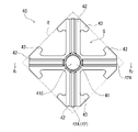
- FIG. 2 is a perspective view of the current collector plate viewed from the first main surface side (the bottom side of the case).
- the current collector plate 40 includes a central first portion 41 , a plurality of second portions 42 radially extending along the first direction (radial direction) away from the first portion 41 , and each of the second portions 42 . It has a plurality of third portions 43 that extend from locations spaced apart from the first portion 41 and protrude in a second direction (circumferential direction) intersecting the first direction. In the adjacent second portions 42, the third portion extending from one second portion to the other second portion is spaced apart from the third portion extending from the other second portion to the one second portion. there is That is, a gap is formed between the third portion extending from the one second portion and the third portion extending from the other second portion.
- the current collector plate 40 has a plate shape having a first main surface S1 and a second main surface S2 opposite to the first main surface S1 (rear surface).
- the current collecting plate 40 is, for example, a metal plate, which is punched into a predetermined shape and then processed into a shape having unevenness by press molding.
- the current collector plate 40 is arranged in the battery, it is arranged between the case bottom and the winding body such that the first principal surface S1 faces the case bottom and the second principal face S2 faces the winding body. be done.
- FIG. 2 shows the appearance of the current collector plate viewed from the first main surface S1 side (the bottom side of the case).
- the first portion 41 has a protruding surface 41S protruding toward the first main surface S1.
- the projecting surface 41S contacts the bottom surface of the battery case, and the current collecting plate 40 and the case are electrically connected.
- the second portion 42 has a projecting surface 42S that projects toward the second main surface S2.
- the projecting surface extends along the direction in which the second portion 42 extends, and when viewed from the first main surface side, a groove portion 42A extending along the direction in which the second portion 42 extends is formed.
- the collector plate 40 and one electrode of the wound body are electrically connected.
- a gap G is interposed between the adjacent second portions 42 and between the adjacent third portions 43 continuously from the adjacent second portions 42 . Via this gap G, the gas generated at the time of abnormal heat generation can be released efficiently. Since the adjacent third portions 43 extend from the tips of the second portions 42 so as to approach each other, the width of the gap G between the second portions 42 is greater than the width of the gap G between the third portions 43. also widens.
- the third portion 43 extends so as to protrude from the second portion 42 on both sides in a direction substantially perpendicular to the direction in which the second portion 42 extends, thereby preventing the wound body from jumping out of the case. It has the effect of holding down and fixing.
- the current collector plate 40 in the current collector plate 40, four second portions 42 radially extend from the first portion 41 so as to form an angle of 90° with each other. Further, the third portion 43 extends from the tip of the second portion 42 while retreating toward the first portion 41 so that the second portion and the overall shape of the third portion 43 that is continuous with the second portion forms an arrowhead. ing. As a result, a portion of the contour of each of the plurality of third portions 43 touches the predetermined square R, as can be seen from FIG. 1A. As a result, the overall contour shape of the current collector plate 40 is a shape inscribed in a square.
- both the effect of fixing the wound body and the effect of efficiently exhausting gas can be achieved in a high state.
- the current collector plate 40 has a contour shape inscribed in a square, residue is reduced when the current collector plate 40 is manufactured by punching a metal plate, and production efficiency is improved.
- a current collector plate 40A shown in FIG. 3A is an example in which the third portion 43 is arranged to extend in an arc shape from the tip of the second portion 42 .
- the arcuate third portion 43 can be arranged to extend along the inner peripheral wall of the battery case when arranged inside the battery.
- FIG. 4 is a side view showing the appearance of the battery 200 according to this embodiment in which the current collector plate 40 is arranged.
- FIG. 5 is a schematic diagram showing a partially cutaway case 210 showing a state where the case 210 and the current collector plate 40 are arranged.
- FIG. 6 is a longitudinal sectional view showing the internal structure of battery 200 on the bottom side of case 210 .
- the negative electrode 20 is in the form of a long sheet, and includes a negative electrode current collector and a negative electrode active material layer carried thereon.
- the negative electrode active material layer is formed on both sides of the negative electrode current collector.
- a negative electrode current collector exposed portion 21x having no negative electrode active material layer is formed at one end along the longitudinal direction of the negative electrode current collector.
- the current collector plate 40 is in contact with the negative electrode current collector exposed portion 21x in a groove portion 42A formed in the second portion 42 thereof and protruding toward the second main surface side opposite to the first main surface S1. .
- the current collector plate 40 and the negative electrode current collector exposed portion 21x are welded. Therefore, the case 210 functions as an external negative terminal.
- a thin portion 210X is provided at the bottom of the case 210.
- the case 210 breaks at the thin portion 210X, and the gas is exhausted.
- the third portion 43 of the current collector plate 40 serves to fix the wound body 100 within the case 210 as the gas is exhausted.
- the third portion 43 also extends on the outer peripheral side from the location where the thin portion 210X is provided so as not to hinder gas exhaust.
- the inner surface of the bottom of the case 210 is not flat, and has an annular recess 210A on the outer peripheral side.
- the tip of the third portion 43 of the current collector plate 40 may protrude toward the first main surface S1 so as to engage with the recess 210A.
- the protruding portion of the third portion 43 comes into contact with the case 210, so that the electrical connection between the current collector plate 40 and the case 210 is improved. can enhance the effect of being fixed.
- a through-hole may be provided in the first portion 41 in order to facilitate injection of the electrolytic solution during manufacturing and to further facilitate gas discharge during abnormal heat generation. Since the first portion 41 faces the hollow region of the core portion of the wound body 100, the gas from the hollow region is discharged by providing a through hole in the first portion 41 and forming a gas exhaust path. becomes easier.
- FIG. 7 shows an example of a current collector plate 40C in which a protruding portion 43A protruding toward the first main surface S1 is provided at the tip of the third portion 43, and a through hole 41H is provided in the first portion 41.
- the third portion 43 extending in the second direction is bent at the tip to form a projecting portion 43A projecting toward the first main surface S1.
- the projecting portion 43A is not limited to this configuration, and for example, the thickness of the third portion 43 may be increased at the distal end portion to project toward the first main surface S1.
- the through hole 41H is provided at the center of the projecting surface 41S of the first portion 41.
- the present invention is not limited to this. may be set to However, in that case, the through-hole 41H should be located at a position not facing the groove 42A in the circumferential direction (for example, , at a position facing the gap G).
- FIGS. 8A and 8B show another example of a current collector plate having through holes 41H provided in the first portion 41.
- FIG. 8A and 8B are enlarged top views showing the periphery of the first portion of the current collector plate.
- the through hole 41H is provided inside the welding position 41X with the case bottom.
- the through hole 41H may be cross-shaped as shown in FIG. 8A, and its shape is not particularly limited. Also, a plurality of through holes 41H may be arranged as shown in FIG. 8B.
- the material forming the current collector plate 40 is determined according to the material forming the positive electrode and the negative electrode.
- the material of the current collector plate 40 when used as a negative electrode current collector plate for a lithium ion secondary battery, is, for example, copper, copper alloy, nickel, stainless steel, or the like.
- the material of the negative electrode current collector may be the same as the material of the negative electrode current collector 21 .
- the material of the collector plate 40 when used as a positive collector plate for a lithium-ion secondary battery, is, for example, aluminum, an aluminum alloy, titanium, stainless steel, or the like.
- the material of the positive electrode current collector may be the same as the material of the positive electrode current collector.
- the temperature of the second portion rises more when the outside of the second portion is welded than when the inside of the second portion is welded.
- the outer side of the second portion 42 is easily melted during welding. Then, in the radial direction, the reliability of welding of the joint between the outside of the second portion 42 of the current collector plate 40 and one of the positive electrode and the negative electrode can be improved.
- the current collection path of the wound body 100 in the winding direction is greater in the outer portion than in the inner portion of the wound body.
- the distance between the connection points with the two parts is increased. Therefore, the current collection path in the winding direction becomes longer on the outer side of the wound body 100 .
- the current collection path in the winding body tends to be longer than when the welding failure occurs on the inside, and the current collection resistance of the power storage device 200 tends to deteriorate. . Therefore, by increasing the welding reliability outside the second portion 42 of the current collector plate 40 in the radial direction, deterioration of current collection resistance when current is collected from the wound body 100 to the current collector plate 40 can be prevented. can be suppressed.
- a sheet-like metal material is used for the positive electrode current collector.
- the sheet-shaped metal material may be a metal foil, a metal porous body, an etched metal, or the like. Aluminum, an aluminum alloy, nickel, titanium, etc. can be used as the metal material.
- the thickness of the positive electrode current collector is, for example, 10 ⁇ m to 100 ⁇ m.
- the negative electrode current collector A sheet-like metal material is used for the negative electrode current collector.
- the sheet-shaped metal material may be a metal foil, a metal porous body, an etched metal, or the like.
- metal materials copper, copper alloys, nickel, stainless steel, and the like can be used.
- the thickness of the negative electrode current collector is, for example, 10 ⁇ m to 100 ⁇ m.
- the negative electrode active material layer contains, for example, a negative electrode active material, a conductive agent, and a binder.
- the negative electrode active material layer is obtained, for example, by applying a negative electrode mixture slurry containing a negative electrode active material, a conductive material, and a binder on both sides of a negative electrode current collector, drying the coating film, and then rolling.
- a negative electrode active material is a material that absorbs and releases lithium ions. Examples of negative electrode active materials include carbon materials, metal compounds, alloys, and ceramic materials.
- separator for example, a microporous film made of resin such as polyolefin, woven fabric, non-woven fabric, or the like can be used.
- the thickness of the separator is, for example, 10-300 ⁇ m, preferably 10-40 ⁇ m.
- Non-aqueous electrolyte has lithium ion conductivity and contains a lithium salt and a non-aqueous solvent that dissolves the lithium salt.
- the current collector plate according to the present disclosure can be used to realize a high-output power storage device, and is therefore suitable for in-vehicle use, for example.
Abstract
Description
前記第2部分の前記第1部分から離間した箇所から延びて、前記第1方向に交差する第2方向に突出する複数の第3部分と、を有し、隣り合う2つの前記第2部分において、一方の前記第2部分から延びる第3部分と他方の前記第2部分から延びる第3部分との間に隙間が形成されている、集電板に関する。 One aspect of the present disclosure is a plate having a first main surface and a second main surface opposite to the first main surface, a first portion in the center, and a first portion extending in a first direction away from the first portion. a plurality of second portions;
a plurality of third portions extending from a portion of the second portion spaced apart from the first portion and protruding in a second direction intersecting the first direction; and a current collector plate in which a gap is formed between a third portion extending from one of the second portions and a third portion extending from the other of the second portions.
正極集電体には、シート状の金属材料が用いられる。シート状の金属材料は、金属箔、金属多孔体、エッチングメタルなどであればよい。金属材料としては、アルミニウム、アルミニウム合金、ニッケル、チタンなどを用い得る。正極集電体の厚みは、例えば10μm~100μmである。 (positive electrode)
A sheet-like metal material is used for the positive electrode current collector. The sheet-shaped metal material may be a metal foil, a metal porous body, an etched metal, or the like. Aluminum, an aluminum alloy, nickel, titanium, etc. can be used as the metal material. The thickness of the positive electrode current collector is, for example, 10 μm to 100 μm.
負極集電体には、シート状の金属材料が用いられる。シート状の金属材料は、金属箔、金属多孔体、エッチングメタルなどであればよい。金属材料としては、銅、銅合金、ニッケル、ステンレス鋼などを用い得る。負極集電体の厚みは、例えば10μm~100μmである。 (negative electrode)
A sheet-like metal material is used for the negative electrode current collector. The sheet-shaped metal material may be a metal foil, a metal porous body, an etched metal, or the like. As metal materials, copper, copper alloys, nickel, stainless steel, and the like can be used. The thickness of the negative electrode current collector is, for example, 10 μm to 100 μm.
セパレータとしては、例えば、ポリオレフィンなどの樹脂製の微多孔膜、織布、不織布などを用い得る。セパレータの厚みは、例えば10~300μmであり、10~40μmが好ましい。 (separator)
As the separator, for example, a microporous film made of resin such as polyolefin, woven fabric, non-woven fabric, or the like can be used. The thickness of the separator is, for example, 10-300 μm, preferably 10-40 μm.
非水電解質は、リチウムイオン伝導性を有し、リチウム塩と、リチウム塩を溶解させる非水溶媒とを含む。 (Non-aqueous electrolyte)
The non-aqueous electrolyte has lithium ion conductivity and contains a lithium salt and a non-aqueous solvent that dissolves the lithium salt.
10:正極
13:絶縁層
20:負極
21x:負極集電体露出部
30:セパレータ
40、40A~40C:集電板
41:第1部分
41S:突出面
42:第2部分
42A:溝部
42S:突出面
43:第3部分
43A:突出部
200:電池(蓄電装置)
210:ケース
210A:凹み
210X:薄肉部 100: Wound body 10: Positive electrode 13: Insulating layer 20:
210:
Claims (13)
- 第1主面および前記第1主面と反対側の第2主面を有する板状であり、
中央の第1部分と、
前記第1部分から遠ざかる第1方向に延びる複数の第2部分と、
前記第2部分の前記第1部分から離間した箇所から延びて、前記第1方向に交差する第2方向に突出する複数の第3部分と、を有し、
隣り合う2つの前記第2部分において、一方の前記第2部分から延びる第3部分と他方の前記第2部分から延びる第3部分との間に隙間が形成されている、
集電板。 A plate having a first main surface and a second main surface opposite to the first main surface,
a central first portion;
a plurality of second portions extending in a first direction away from the first portion;
a plurality of third portions extending from a portion of the second portion spaced apart from the first portion and protruding in a second direction intersecting the first direction;
In the two adjacent second portions, a gap is formed between a third portion extending from one of the second portions and a third portion extending from the other of the second portions.
current collector. - 3つ以上の前記第2部分を有し、隣り合う前記第2部分の間、および、隣り合う前記第3部分の間には隙間が介在し、且つ、前記第2部分の間の隙間は、前記第3部分の間の隙間よりも広い、
請求項1に記載の集電板。 It has three or more second portions, gaps are interposed between the adjacent second portions and between the adjacent third portions, and the gaps between the second portions are wider than the gap between said third portions;
The current collector plate according to claim 1 . - 前記第2部分に、前記第2主面の側に突出しながら前記第1方向に延びる溝部が形成されている、
請求項1または2に記載の集電板。 A groove extending in the first direction while protruding toward the second main surface is formed in the second portion,
The current collector plate according to claim 1 or 2. - 前記第1部分は、前記第1主面の側に突出する突出面を有する、
請求項1~3のいずれか1項に記載の集電板。 The first portion has a protruding surface that protrudes toward the first main surface,
The current collector plate according to any one of claims 1 to 3. - 4つの前記第2部分が、前記第1部分から互いに90°の角度をなすように放射状に延びており、
前記複数の第3部分のそれぞれの輪郭の一部が、所定の正方形に接している、
請求項1~4のいずれか1項に記載の集電板。 four said second portions radially extending from said first portion at 90° angles to each other;
a portion of the contour of each of the plurality of third portions is tangent to a predetermined square;
The current collector plate according to any one of claims 1 to 4. - 前記第3部分は、前記第1主面側に突出する突出部を有する、
請求項1~5のいずれか1項に記載の集電板。 The third portion has a protruding portion that protrudes toward the first main surface,
The current collector plate according to any one of claims 1 to 5. - 前記第1部分は、貫通孔を有する、
請求項1~6のいずれか1項に記載の集電板。 The first portion has a through hole,
The current collector plate according to any one of claims 1 to 6. - 前記第1主面および前記第2主面に積層されためっき層をさらに有し、
前記第1主面側のめっき層の厚みは、前記第2主面側のめっき層の厚みよりも薄い、
請求項1~7のいずれか1項に記載の集電板。 Further having a plating layer laminated on the first main surface and the second main surface,
The thickness of the plating layer on the first main surface side is thinner than the thickness of the plating layer on the second main surface side,
The current collector plate according to any one of claims 1 to 7. - 正極および負極がセパレータを介して巻回された柱状の巻回体と、
前記巻回体を収容するケースと、
請求項1~8のいずれか1項に記載の集電板と、を備え、
前記ケースは、筒部と、前記筒部の一端を閉じる底部と、を有し、
前記集電板の少なくとも前記第1部分は、前記第1主面側において前記ケースの前記底部と電気的に接続するとともに、前記集電板の少なくとも前記第2部分は、前記第2主面側において、前記巻回体の前記第2主面に対向する端面における前記正極および前記負極のいずれか一方の電極と接合されている、
蓄電装置。 a columnar wound body in which the positive electrode and the negative electrode are wound with a separator interposed therebetween;
a case that accommodates the wound body;
A current collector plate according to any one of claims 1 to 8,
The case has a tubular portion and a bottom portion that closes one end of the tubular portion,
At least the first portion of the current collector plate is electrically connected to the bottom portion of the case on the first main surface side, and at least the second portion of the current collector plate is on the second main surface side. wherein the positive electrode or the negative electrode on the end face facing the second main surface of the wound body is joined,
storage device. - 前記ケースの前記底部に、防爆機構が設けられ、
前記防爆機構は、前記集電板の前記第3部分よりも内周側にあって前記第3部分と重ならない領域に設けられている、
請求項9に記載の蓄電装置。 An explosion-proof mechanism is provided at the bottom of the case,
The explosion-proof mechanism is provided in a region that is located on the inner peripheral side of the third portion of the current collector plate and does not overlap with the third portion.
The power storage device according to claim 9 . - 前記ケースの前記底部の前記第1主面と対向する面に凹みが形成され、
前記凹みが、前記集電板の前記第3部分に設けられた突出部と係合している、
請求項9または10に記載の蓄電装置。 a recess is formed in a surface of the bottom of the case facing the first main surface;
the recess is engaged with a protrusion provided on the third portion of the current collector plate;
The power storage device according to claim 9 or 10. - 前記集電板の前記第2部分は前記一方の電極と溶接により接合され、
前記第2部分に前記第1方向に延びた線状の溶接痕が形成され、
前記溶接痕が延びる方向の両端において、前記第1部分側の前記溶接痕の第1端部が、溶接始点であり、前記第1部分から遠い側の前記溶接痕の第2端部が溶接終点である、
請求項9~11のいずれか一項に記載の蓄電装置。 The second portion of the current collector plate is joined to the one electrode by welding,
A linear weld mark extending in the first direction is formed on the second portion,
At both ends in the direction in which the weld scar extends, the first end of the weld scar on the first portion side is the welding start point, and the second end of the weld scar on the far side from the first portion is the weld end point. is
The power storage device according to any one of claims 9 to 11. - 前記集電板の前記第2部分の前記一方の電極と接合した部分は、前記第1方向において、前記第1部分側の第1領域と、前記第1領域より外側に位置する第2領域とを有し、
前記巻回体の巻回軸方向において、前記第1領域より前記第2領域が前記一方の電極側に位置するように、前記第2部分は曲がっている、
請求項9~12のいずれか一項に記載の蓄電装置。 The portion of the second portion of the current collector plate that is joined to the one electrode includes a first region on the first portion side and a second region located outside the first region in the first direction. has
The second portion is bent such that the second region is positioned closer to the one electrode than the first region in the winding axial direction of the wound body.
The power storage device according to any one of claims 9 to 12.
Priority Applications (2)
| Application Number | Priority Date | Filing Date | Title |
|---|---|---|---|
| CN202280050091.2A CN117795759A (en) | 2021-07-16 | 2022-07-07 | Collector plate and power storage device using same |
| JP2023534757A JPWO2023286687A1 (en) | 2021-07-16 | 2022-07-07 |
Applications Claiming Priority (2)
| Application Number | Priority Date | Filing Date | Title |
|---|---|---|---|
| JP2021-118059 | 2021-07-16 | ||
| JP2021118059 | 2021-07-16 |
Publications (1)
| Publication Number | Publication Date |
|---|---|
| WO2023286687A1 true WO2023286687A1 (en) | 2023-01-19 |
Family
ID=84919350
Family Applications (1)
| Application Number | Title | Priority Date | Filing Date |
|---|---|---|---|
| PCT/JP2022/026934 WO2023286687A1 (en) | 2021-07-16 | 2022-07-07 | Collector plate and power storage device using same |
Country Status (3)
| Country | Link |
|---|---|
| JP (1) | JPWO2023286687A1 (en) |
| CN (1) | CN117795759A (en) |
| WO (1) | WO2023286687A1 (en) |
Citations (6)
| Publication number | Priority date | Publication date | Assignee | Title |
|---|---|---|---|---|
| JPH10188997A (en) * | 1996-12-26 | 1998-07-21 | Sanou Kogyo Kk | Collector for battery |
| JPH1131497A (en) * | 1997-05-12 | 1999-02-02 | Matsushita Electric Ind Co Ltd | Cylindrical battery |
| JP2001256954A (en) * | 2000-03-10 | 2001-09-21 | Sony Corp | Electricity storage device |
| JP2005203374A (en) | 2004-01-16 | 2005-07-28 | Samsung Sdi Co Ltd | Secondary battery |
| JP2009259452A (en) * | 2008-04-14 | 2009-11-05 | Toyota Motor Corp | Battery and its method for manufacturing |
| WO2021024734A1 (en) * | 2019-08-08 | 2021-02-11 | 株式会社村田製作所 | Secondary battery, battery pack, electronic device, electric tool and electric vehicle |
-
2022
- 2022-07-07 WO PCT/JP2022/026934 patent/WO2023286687A1/en active Application Filing
- 2022-07-07 CN CN202280050091.2A patent/CN117795759A/en active Pending
- 2022-07-07 JP JP2023534757A patent/JPWO2023286687A1/ja active Pending
Patent Citations (6)
| Publication number | Priority date | Publication date | Assignee | Title |
|---|---|---|---|---|
| JPH10188997A (en) * | 1996-12-26 | 1998-07-21 | Sanou Kogyo Kk | Collector for battery |
| JPH1131497A (en) * | 1997-05-12 | 1999-02-02 | Matsushita Electric Ind Co Ltd | Cylindrical battery |
| JP2001256954A (en) * | 2000-03-10 | 2001-09-21 | Sony Corp | Electricity storage device |
| JP2005203374A (en) | 2004-01-16 | 2005-07-28 | Samsung Sdi Co Ltd | Secondary battery |
| JP2009259452A (en) * | 2008-04-14 | 2009-11-05 | Toyota Motor Corp | Battery and its method for manufacturing |
| WO2021024734A1 (en) * | 2019-08-08 | 2021-02-11 | 株式会社村田製作所 | Secondary battery, battery pack, electronic device, electric tool and electric vehicle |
Also Published As
| Publication number | Publication date |
|---|---|
| CN117795759A (en) | 2024-03-29 |
| JPWO2023286687A1 (en) | 2023-01-19 |
Similar Documents
| Publication | Publication Date | Title |
|---|---|---|
| JP6505859B2 (en) | Nonaqueous electrolyte secondary battery | |
| JP6089784B2 (en) | Prismatic secondary battery | |
| CN109768339B (en) | Secondary battery | |
| JP5966924B2 (en) | Method for manufacturing electrode plate unit for lithium ion capacitor and lithium ion capacitor | |
| KR20100089092A (en) | Secondary battery | |
| KR20090132500A (en) | Electrode assembly and secondary battery with the same and method of thereof | |
| JP5137516B2 (en) | Sealed battery | |
| JPWO2014097586A1 (en) | Cylindrical secondary battery and manufacturing method thereof | |
| JP2010003696A (en) | Electrode tab, and lithium secondary battery including it | |
| JP4688688B2 (en) | Secondary battery for large current discharge | |
| US7776469B2 (en) | Secondary battery having a current collecting plate with improved welding characteristics | |
| JP2004356085A (en) | Jelly roll type electrode assembly and secondary battery adopting this | |
| JP2022185087A (en) | Square secondary battery | |
| CN116111293A (en) | Tab welding structure, battery and electronic product | |
| JP6878878B2 (en) | Rechargeable battery manufacturing method and rechargeable battery | |
| WO2023286687A1 (en) | Collector plate and power storage device using same | |
| WO2022059797A1 (en) | Power storage device | |
| JP2019067544A (en) | Secondary battery and manufacturing method thereof | |
| JP7278154B2 (en) | electrochemical cell | |
| JP2004273288A (en) | Cylindrical secondary battery | |
| EP4318515A1 (en) | Power storage device | |
| JP4428965B2 (en) | Battery unit | |
| WO2022059788A1 (en) | Power storage device | |
| CN111919312A (en) | Cylindrical battery and method for manufacturing same | |
| KR102539637B1 (en) | Primary battery manufacturing method with increased product reliability and productivity |
Legal Events
| Date | Code | Title | Description |
|---|---|---|---|
| 121 | Ep: the epo has been informed by wipo that ep was designated in this application |
Ref document number: 22842031 Country of ref document: EP Kind code of ref document: A1 |
|
| WWE | Wipo information: entry into national phase |
Ref document number: 2023534757 Country of ref document: JP |
|
| WWE | Wipo information: entry into national phase |
Ref document number: 2022842031 Country of ref document: EP |
|
| NENP | Non-entry into the national phase |
Ref country code: DE |
|
| ENP | Entry into the national phase |
Ref document number: 2022842031 Country of ref document: EP Effective date: 20240216 |