WO2023286635A1 - 基板洗浄装置 - Google Patents
基板洗浄装置 Download PDFInfo
- Publication number
- WO2023286635A1 WO2023286635A1 PCT/JP2022/026392 JP2022026392W WO2023286635A1 WO 2023286635 A1 WO2023286635 A1 WO 2023286635A1 JP 2022026392 W JP2022026392 W JP 2022026392W WO 2023286635 A1 WO2023286635 A1 WO 2023286635A1
- Authority
- WO
- WIPO (PCT)
- Prior art keywords
- substrate
- brush
- cleaning
- surface brush
- liquid
- Prior art date
- Legal status (The legal status is an assumption and is not a legal conclusion. Google has not performed a legal analysis and makes no representation as to the accuracy of the status listed.)
- Ceased
Links
Images








Classifications
-
- B—PERFORMING OPERATIONS; TRANSPORTING
- B08—CLEANING
- B08B—CLEANING IN GENERAL; PREVENTION OF FOULING IN GENERAL
- B08B1/00—Cleaning by methods involving the use of tools
- B08B1/30—Cleaning by methods involving the use of tools by movement of cleaning members over a surface
- B08B1/32—Cleaning by methods involving the use of tools by movement of cleaning members over a surface using rotary cleaning members
- B08B1/34—Cleaning by methods involving the use of tools by movement of cleaning members over a surface using rotary cleaning members rotating about an axis parallel to the surface
-
- B—PERFORMING OPERATIONS; TRANSPORTING
- B08—CLEANING
- B08B—CLEANING IN GENERAL; PREVENTION OF FOULING IN GENERAL
- B08B1/00—Cleaning by methods involving the use of tools
- B08B1/10—Cleaning by methods involving the use of tools characterised by the type of cleaning tool
- B08B1/12—Brushes
-
- B—PERFORMING OPERATIONS; TRANSPORTING
- B08—CLEANING
- B08B—CLEANING IN GENERAL; PREVENTION OF FOULING IN GENERAL
- B08B1/00—Cleaning by methods involving the use of tools
- B08B1/30—Cleaning by methods involving the use of tools by movement of cleaning members over a surface
- B08B1/32—Cleaning by methods involving the use of tools by movement of cleaning members over a surface using rotary cleaning members
-
- B—PERFORMING OPERATIONS; TRANSPORTING
- B08—CLEANING
- B08B—CLEANING IN GENERAL; PREVENTION OF FOULING IN GENERAL
- B08B1/00—Cleaning by methods involving the use of tools
- B08B1/30—Cleaning by methods involving the use of tools by movement of cleaning members over a surface
- B08B1/32—Cleaning by methods involving the use of tools by movement of cleaning members over a surface using rotary cleaning members
- B08B1/36—Cleaning by methods involving the use of tools by movement of cleaning members over a surface using rotary cleaning members rotating about an axis orthogonal to the surface
-
- B—PERFORMING OPERATIONS; TRANSPORTING
- B08—CLEANING
- B08B—CLEANING IN GENERAL; PREVENTION OF FOULING IN GENERAL
- B08B1/00—Cleaning by methods involving the use of tools
- B08B1/50—Cleaning by methods involving the use of tools involving cleaning of the cleaning members
- B08B1/52—Cleaning by methods involving the use of tools involving cleaning of the cleaning members using fluids
-
- H—ELECTRICITY
- H10—SEMICONDUCTOR DEVICES; ELECTRIC SOLID-STATE DEVICES NOT OTHERWISE PROVIDED FOR
- H10P—GENERIC PROCESSES OR APPARATUS FOR THE MANUFACTURE OR TREATMENT OF DEVICES COVERED BY CLASS H10
- H10P52/00—Grinding, lapping or polishing of wafers, substrates or parts of devices
-
- H—ELECTRICITY
- H10—SEMICONDUCTOR DEVICES; ELECTRIC SOLID-STATE DEVICES NOT OTHERWISE PROVIDED FOR
- H10P—GENERIC PROCESSES OR APPARATUS FOR THE MANUFACTURE OR TREATMENT OF DEVICES COVERED BY CLASS H10
- H10P72/00—Handling or holding of wafers, substrates or devices during manufacture or treatment thereof
- H10P72/04—Apparatus for manufacture or treatment
- H10P72/0402—Apparatus for fluid treatment
- H10P72/0406—Apparatus for fluid treatment for cleaning followed by drying, rinsing, stripping, blasting or the like
- H10P72/0411—Apparatus for fluid treatment for cleaning followed by drying, rinsing, stripping, blasting or the like for wet cleaning or washing
- H10P72/0412—Apparatus for fluid treatment for cleaning followed by drying, rinsing, stripping, blasting or the like for wet cleaning or washing using mainly scrubbing means, e.g. brushes
-
- H—ELECTRICITY
- H10—SEMICONDUCTOR DEVICES; ELECTRIC SOLID-STATE DEVICES NOT OTHERWISE PROVIDED FOR
- H10P—GENERIC PROCESSES OR APPARATUS FOR THE MANUFACTURE OR TREATMENT OF DEVICES COVERED BY CLASS H10
- H10P72/00—Handling or holding of wafers, substrates or devices during manufacture or treatment thereof
- H10P72/04—Apparatus for manufacture or treatment
- H10P72/0402—Apparatus for fluid treatment
- H10P72/0406—Apparatus for fluid treatment for cleaning followed by drying, rinsing, stripping, blasting or the like
- H10P72/0411—Apparatus for fluid treatment for cleaning followed by drying, rinsing, stripping, blasting or the like for wet cleaning or washing
- H10P72/0414—Apparatus for fluid treatment for cleaning followed by drying, rinsing, stripping, blasting or the like for wet cleaning or washing using mainly spraying means, e.g. nozzles
Definitions
- the present invention relates to a substrate cleaning apparatus that cleans the bottom surface of a substrate.
- FPD Fluorescence Plated Device
- substrate processing apparatuses are used to perform various types of processing on various types of substrates such as substrates for solar cells.
- a substrate cleaning apparatus is used to clean the substrate.
- the substrate cleaning apparatus described in Patent Document 1 includes two suction pads that hold the peripheral portion of the back surface of the wafer, a spin chuck that holds the central portion of the back surface of the wafer, and a brush that cleans the back surface of the wafer.
- Two suction pads hold the wafer and move laterally.
- the central portion of the back surface of the wafer is cleaned with a brush.
- the spin chuck receives the wafer from the suction pad, and the spin chuck rotates while holding the central portion of the back surface of the wafer.
- the peripheral portion of the back surface of the wafer is cleaned with a brush.
- the cleanliness of the brush gradually decreases. If the cleanliness of the brush is reduced, the substrate cannot be cleaned efficiently. Therefore, it is required to maintain the cleanliness of the brush at a certain level or higher. However, maintaining brush cleanliness without reducing throughput is not easy.
- An object of the present invention is to provide a substrate cleaning apparatus capable of maintaining the cleanliness of brushes without lowering throughput.
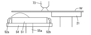
- a substrate cleaning apparatus includes a substrate holding section that holds a substrate in a horizontal position, a processing position for cleaning the substrate, and a standby position that vertically overlaps the substrate held by the substrate holding section. and a lower brush that contacts the lower surface of the substrate while rotating about a vertical axis at the processing position; and a second liquid nozzle that discharges the cleaning liquid to the end of the lower surface brush at the standby position.
- the bottom surface of the substrate is cleaned by rotating the bottom brush at the processing position and contacting the bottom surface of the substrate. Further, even if the mask brush is contaminated by cleaning the lower surface of the substrate, the cleaning liquid is sprayed by the first liquid nozzle and the second liquid nozzle on the central portion and the end portion of the rotated lower surface brush at the standby position, respectively. Dispensed. According to this configuration, the lower surface brush can be washed as a whole.
- the standby position of the lower surface brush vertically overlaps the substrate held by the substrate holding portion, even if the lower surface brush is relatively large, the footprint hardly increases. Therefore, by using a relatively large bottom surface brush, it is possible to clean the bottom surface of the substrate in a short time. Therefore, even if a step of cleaning the lower surface brush is provided, the throughput hardly changes. Thereby, the cleanliness of the lower surface brush can be maintained without lowering the throughput.
- the substrate cleaning apparatus further includes a support for supporting the lower surface brush, and each of the first liquid nozzle and the second liquid nozzle is attached to the support so that the discharge port of the cleaning liquid faces obliquely upward.
- the lower surface brush can be easily cleaned without hindering the cleaning of the lower surface of the substrate by the lower surface brush.
- the first liquid nozzle may discharge the cleaning liquid so that the cleaning liquid is supplied obliquely from above to the central portion of the lower surface brush in a parabolic shape.
- the central portion of the lower surface brush can be easily cleaned without hindering the cleaning of the lower surface of the substrate by the lower surface brush.
- the lower surface brush may be made of fluorine-based resin.
- the wettability of the lower surface brush is relatively low.
- the lower surface brush can be made less likely to be contaminated.
- the cleaning liquid is discharged to the central portion and the end portion of the lower surface brush by the first liquid nozzle and the second liquid nozzle, respectively, the lower surface brush is uniformly wetted even if the wettability of the lower surface brush is relatively low. Therefore, partial hardening of the lower surface brush is prevented. As a result, the bottom surface of the substrate can be uniformly cleaned.
- Each of the substrate holder and the lower brush may have a circular outer shape, and the diameter of the lower brush may be larger than the diameter of the substrate holder.
- the bottom brush is relatively large. Therefore, the bottom surface of the substrate can be efficiently cleaned.
- the cleaning liquid is discharged to the central portion and the end portion of the lower surface brush by the first liquid nozzle and the second liquid nozzle, respectively, the lower surface brush is uniformly wetted even if the lower surface brush is relatively large. Therefore, partial hardening of the lower surface brush is prevented. As a result, the bottom surface of the substrate can be uniformly cleaned.
- Each of the substrate and the bottom brush may have a circular outer shape, and the diameter of the bottom brush may be greater than 1/3 of the diameter of the substrate.
- the bottom brush is relatively large. Therefore, the bottom surface of the substrate can be efficiently cleaned.
- the cleaning liquid is discharged to the central portion and the end portion of the lower surface brush by the first liquid nozzle and the second liquid nozzle, respectively, the lower surface brush is uniformly wetted even if the lower surface brush is relatively large. Therefore, partial hardening of the lower surface brush is prevented. As a result, the bottom surface of the substrate can be uniformly cleaned.
- the cleanliness of the lower surface brush can be maintained without reducing throughput.
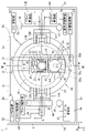
- FIG. 1 is a schematic plan view of a substrate cleaning apparatus according to one embodiment of the present invention.
- 2 is an external perspective view showing the internal configuration of the substrate cleaning apparatus of FIG. 1.
- FIG. 3 is a block diagram showing the configuration of the control system of the substrate cleaning apparatus.
- FIG. 4 is a schematic diagram for explaining the schematic operation of the substrate cleaning apparatus of FIG.
- FIG. 5 is a schematic diagram for explaining the schematic operation of the substrate cleaning apparatus of FIG.
- FIG. 6 is a schematic diagram for explaining the schematic operation of the substrate cleaning apparatus of FIG.
- FIG. 7 is a schematic diagram for explaining the schematic operation of the substrate cleaning apparatus of FIG.
- FIG. 8 is a schematic diagram for explaining the schematic operation of the substrate cleaning apparatus of FIG.
- FIG. 9 is a schematic diagram for explaining the schematic operation of the substrate cleaning apparatus of FIG.
- FIG. 10 is a schematic diagram for explaining the schematic operation of the substrate cleaning apparatus of FIG.
- FIG. 11 is a schematic diagram for explaining the schematic operation of the substrate cleaning apparatus of FIG.
- FIG. 12 is a schematic diagram for explaining the schematic operation of the substrate cleaning apparatus of FIG.
- FIG. 13 is a schematic diagram for explaining the schematic operation of the substrate cleaning apparatus of FIG.
- FIG. 14 is a schematic diagram for explaining the schematic operation of the substrate cleaning apparatus of FIG.
- FIG. 15 is a schematic diagram for explaining the schematic operation of the substrate cleaning apparatus of FIG.
- FIG. 16 is a schematic diagram for explaining the schematic operation of the substrate cleaning apparatus in FIG.
- FIG. 17 is a schematic diagram for explaining the schematic operation of the substrate cleaning apparatus in FIG.
- FIG. 18 is a schematic diagram for explaining the schematic operation of the substrate cleaning apparatus in FIG.
- FIG. 19 is a schematic diagram for explaining the schematic operation of the substrate cleaning apparatus in FIG.
- FIG. 20 is a schematic diagram for explaining the schematic operation of the substrate cleaning apparatus in FIG.
- the substrate means a semiconductor substrate, a substrate for FPD (Flat Panel Display) such as a liquid crystal display device or an organic EL (Electro Luminescence) display device, an optical disk substrate, a magnetic disk substrate, a magneto-optical disk substrate, A photomask substrate, a ceramic substrate, a solar cell substrate, or the like.
- FPD Fluorescence Panel Display
- the substrate used in this embodiment has at least a part of the circular outer peripheral portion.
- the perimeter has a circular shape, except for the positioning notches.
- FIG. 1 is a schematic plan view of a substrate cleaning apparatus according to an embodiment of the present invention.
- FIG. 2 is an external perspective view showing the internal configuration of the substrate cleaning apparatus 1 of FIG.
- X, Y and Z directions which are perpendicular to each other are defined to clarify the positional relationship.
- the X, Y and Z directions are appropriately indicated by arrows.
- the X and Y directions are perpendicular to each other in the horizontal plane, and the Z direction corresponds to the vertical direction.
- the substrate cleaning apparatus 1 includes upper holding devices 10A and 10B, a lower holding device 20, a pedestal device 30, a transfer device 40, a lower cleaning device 50, a cup device 60, an upper cleaning device 70, an end A cleaning device 80 and an opening/closing device 90 are provided. These components are provided within the unit housing 2 . In FIG. 2, the unit housing 2 is indicated by dotted lines.
- the unit housing 2 has a rectangular bottom portion 2a and four side wall portions 2b, 2c, 2d, and 2e extending upward from four sides of the bottom portion 2a. Side wall portions 2b and 2c face each other, and side wall portions 2d and 2e face each other. A rectangular opening is formed in the central portion of the side wall portion 2b. This opening serves as a loading/unloading port 2 x for the substrate W, and is used when the substrate W is loaded into and unloaded from the unit housing 2 . In FIG. 2, the loading/unloading port 2x is indicated by a thick dotted line.
- the direction from the inside of the unit housing 2 to the outside of the unit housing 2 through the loading/unloading port 2x (the direction from the side wall portion 2c to the side wall portion 2b) is referred to as the front.
- the opposite direction (the direction facing the side wall portion 2c from the side wall portion 2b) is called rearward.
- An opening/closing device 90 is provided in a portion of the side wall portion 2b where the loading/unloading port 2x is formed and in a region in the vicinity thereof.
- the opening/closing device 90 includes a shutter 91 capable of opening and closing the loading/unloading port 2x, and a shutter driving section 92 that drives the shutter 91.
- the shutter 91 is indicated by a thick two-dot chain line.
- the shutter drive unit 92 drives the shutter 91 so as to open the loading/unloading port 2 x when the substrate W is loaded into and unloaded from the substrate cleaning apparatus 1 .
- the shutter driving section 92 drives the shutter 91 so as to close the loading/unloading port 2 x during cleaning of the substrate W in the substrate cleaning apparatus 1 .
- a pedestal device 30 is provided in the central portion of the bottom portion 2a.
- the pedestal device 30 includes a linear guide 31 , a movable pedestal 32 and a pedestal driving section 33 .
- the linear guide 31 includes two rails and extends in the Y direction from the vicinity of the side wall portion 2b to the vicinity of the side wall portion 2c in a plan view.
- the movable pedestal 32 is provided so as to be movable in the Y direction on the two rails of the linear guide 31 .
- the pedestal drive unit 33 includes, for example, a pulse motor, and moves the movable pedestal 32 on the linear guide 31 in the Y direction.
- the lower holding device 20 includes a suction holding portion 21 and a suction holding drive portion 22 .
- the suction holding unit 21 is a so-called spin chuck, has a circular suction surface capable of holding the lower surface of the substrate W by suction, and is configured to be rotatable around a vertically extending axis (axis in the Z direction).
- a region of the lower surface of the substrate W to be adsorbed by the adsorption surface of the adsorption holding portion 21 when the substrate W is adsorbed and held by the adsorption holding portion 21 is referred to as a lower surface central region.
- the area surrounding the central area of the lower surface of the lower surface of the substrate W is called the outer area of the lower surface.
- the suction holding drive unit 22 includes a motor.
- the motor of the suction holding drive unit 22 is provided on the movable base 32 so that the rotating shaft protrudes upward.
- the suction holding portion 21 is attached to the upper end portion of the rotating shaft of the suction holding driving portion 22 .
- a suction path for sucking and holding the substrate W in the suction holding unit 21 is formed in the rotating shaft of the suction holding driving unit 22 .
- the suction path is connected to a suction device (not shown).
- the suction holding driving section 22 rotates the suction holding section 21 around the rotation axis.
- a delivery device 40 is further provided near the lower holding device 20 on the movable pedestal 32 .
- the delivery device 40 includes a plurality (three in this example) of support pins 41 , pin connecting members 42 and pin lifting drive units 43 .
- the pin connecting member 42 is formed to surround the suction holding portion 21 in plan view, and connects the plurality of support pins 41 .
- the plurality of support pins 41 are connected to each other by the pin connecting member 42 and extend upward from the pin connecting member 42 by a certain length.
- the pin elevating drive section 43 elevates the pin connecting member 42 on the movable base 32 . As a result, the plurality of support pins 41 move up and down relative to the suction holding portion 21 .
- the lower surface cleaning device 50 includes a lower surface brush 51, two liquid nozzles 52, liquid nozzles 52a and 52b, a gas ejection section 53, an elevation support section 54, a movement support section 55, a lower surface brush rotation drive section 55a, and a lower surface brush elevation drive section 55b. and lower surface brush movement drive unit 55c.
- the movement support part 55 is provided so as to be movable in the Y direction with respect to the lower holding device 20 within a certain area on the movable base 32 . As shown in FIG. 2, on the movement support part 55, the raising/lowering support part 54 is provided so that raising/lowering is possible.
- the lifting support portion 54 has an upper surface 54u that slopes obliquely downward in a direction away from the suction holding portion 21 (rearward in this example).
- the lower surface brush 51 has a circular outer shape in plan view, and is relatively large in the present embodiment. Specifically, the diameter of the lower surface brush 51 is larger than the diameter of the suction surface of the suction holding portion 21 , for example, 1.3 times the diameter of the suction surface of the suction holding portion 21 . In addition, the diameter of the lower surface brush 51 is larger than 1/3 and smaller than 1/2 of the diameter of the substrate W. As shown in FIG. In addition, the diameter of the substrate W is, for example, 300 mm.
- the lower surface brush 51 is preferably made of a material with relatively low wettability, such as fluorine-based resin. In this case, adhesion of contaminants to the lower surface brush 51 is reduced. This makes it difficult for the lower surface brush 51 to become contaminated.
- the lower surface brush 51 is made of PTFE (polytetrafluoroethylene), but the embodiment is not limited to this.
- the lower surface brush 51 may be made of a relatively soft resin material such as PVA (polyvinyl alcohol).
- the lower surface brush 51 has a cleaning surface that can come into contact with the lower surface of the substrate W.
- the lower surface brush 51 is mounted on the upper surface 54u of the elevation support 54 so that the surface to be washed faces upward and is rotatable around an axis extending vertically through the center of the surface to be washed. installed.
- Each of the two liquid nozzles 52 is mounted on the upper surface 54u of the lifting support part 54 so that it is positioned near the lower surface brush 51 and the liquid discharge port faces upward.
- the liquid nozzle 52 is connected to a lower surface cleaning liquid supply section 56 (FIG. 3).
- the lower cleaning liquid supply unit 56 supplies cleaning liquid to the liquid nozzle 52 .
- the liquid nozzle 52 discharges the cleaning liquid supplied from the lower cleaning liquid supply unit 56 onto the lower surface of the substrate W when the substrate W is cleaned by the lower brush 51 .
- pure water is used as the cleaning liquid supplied to the liquid nozzle 52 .
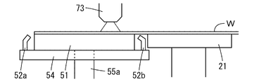
- Each of the two liquid nozzles 52a and 52b is mounted on the upper surface 54u of the elevation support 54 so that it is located near the lower surface brush 51 and the liquid ejection port faces obliquely upward.
- a brush cleaning liquid supply unit 57 (FIG. 3) is connected to the liquid nozzles 52a and 52b.
- the brush cleaning liquid supply unit 57 supplies cleaning liquid to the liquid nozzles 52a and 52b.
- the liquid nozzles 52 a and 52 b discharge the cleaning liquid supplied from the brush cleaning liquid supply section 57 to the central portion and end portions of the cleaning surface of the lower brush 51 when cleaning the lower brush 51 .
- pure water is used as the cleaning liquid supplied to the liquid nozzles 52a and 52b.
- the liquid nozzles 52a and 52b discharge the cleaning liquid to the center and end portions of the cleaning surface of the lower brush 51, respectively. Therefore, even if the lower brush 51 is relatively large or is made of a material with relatively low wettability (PTFE in this example), the cleaning surface of the lower brush 51 is uniformly wetted. This prevents the lower surface brush 51 from partially hardening. As a result, the lower surface of the substrate W can be uniformly cleaned by the lower surface brush 51 .
- the gas ejection part 53 is a slit-shaped gas ejection nozzle having a gas ejection port extending in one direction.
- the gas ejection part 53 is positioned between the lower surface brush 51 and the adsorption holding part 21 in a plan view, and is attached to the upper surface 54u of the elevation support part 54 so that the gas ejection port faces upward.
- a jetting gas supply portion 58 ( FIG. 3 ) is connected to the gas jetting portion 53 .
- the jetting gas supply unit 58 supplies gas to the gas jetting unit 53 .
- an inert gas such as nitrogen gas is used as the gas supplied to the gas ejection part 53 .
- the gas ejection part 53 injects the gas supplied from the ejection gas supply part 58 to the bottom surface of the substrate W when the bottom surface brush 51 cleans the substrate W and dries the bottom surface of the substrate W, which will be described later.
- a strip-shaped gas curtain extending in the X direction is formed between the lower surface brush 51 and the suction holding portion 21 .
- the lower surface brush rotation driving unit 55a includes a motor, and rotates the lower surface brush 51 when the substrate W is cleaned by the lower surface brush 51.
- the lower surface brush elevation driving section 55 b includes a stepping motor or an air cylinder, and raises and lowers the elevation support section 54 with respect to the movement support section 55 .
- the lower surface brush movement drive section 55c includes a motor, and moves the movement support section 55 on the movable base 32 in the Y direction.
- the position of the lower holding device 20 on the movable base 32 is fixed. Therefore, when the movement support portion 55 is moved in the Y direction by the lower surface brush movement driving portion 55c, the movement support portion 55 moves relative to the lower holding device 20.
- the position of the lower cleaning device 50 on the movable pedestal 32 when it comes closest to the lower holding device 20 is called an approach position
- the lower cleaning device 50 on the movable pedestal 32 when it is furthest away from the lower holding device 20 is called an approach position
- the position of device 50 is called the spaced position.
- a cup device 60 is further provided in the central portion of the bottom portion 2a.
- Cup device 60 includes cup 61 and cup drive 62 .
- the cup 61 is provided so as to surround the lower holding device 20 and the pedestal device 30 in plan view and can be raised and lowered. In FIG. 2 the cup 61 is shown in dashed lines.
- the cup drive unit 62 moves the cup 61 between the lower cup position and the upper cup position depending on which portion of the lower surface of the substrate W is to be cleaned by the lower surface brush 51 .
- the lower cup position is a height position where the upper end of the cup 61 is below the substrate W sucked and held by the suction holding portion 21 .
- the upper cup position is a height position where the upper end of the cup 61 is higher than the suction holding portion 21 .
- the upper holding device 10A includes a lower chuck 11A, an upper chuck 12A, a lower chuck driving section 13A and an upper chuck driving section 14A.
- the upper holding device 10B includes a lower chuck 11B, an upper chuck 12B, a lower chuck driving section 13B and an upper chuck driving section 14B.
- the lower chucks 11A and 11B are arranged symmetrically with respect to a vertical plane extending in the Y direction (front-rear direction) through the center of the suction holding portion 21 in plan view, and are provided movably in the X direction within a common horizontal plane. .
- Each of the lower chucks 11A and 11B has two supporting pieces capable of supporting the peripheral portion of the lower surface of the substrate W from below.
- the lower chuck drive units 13A and 13B move the lower chucks 11A and 11B so that the lower chucks 11A and 11B approach each other or move away from each other.
- the upper chucks 12A and 12B are arranged symmetrically with respect to a vertical plane extending in the Y direction (front-rear direction) through the center of the suction holding portion 21 in a plan view. It is provided so as to be movable in the direction.
- Each of the upper chucks 12A and 12B has two holding pieces configured to be able to hold the outer peripheral edge of the substrate W by contacting two portions of the outer peripheral edge of the substrate W.
- the upper chuck drive units 14A, 14B move the upper chucks 12A, 12B so that the upper chucks 12A, 12B come closer to each other or move away from each other.
- an upper surface cleaning device 70 is provided so as to be positioned near the upper holding device 10B in plan view.
- the upper surface cleaning device 70 includes a rotary support shaft 71 , an arm 72 , a spray nozzle 73 and an upper surface cleaning drive section 74 .
- the rotation support shaft 71 is supported by the upper surface cleaning drive unit 74 so as to extend vertically, move up and down, and rotate on the bottom surface portion 2a.
- the arm 72 is provided so as to extend horizontally from the upper end of the rotation support shaft 71 at a position above the upper holding device 10B.
- a spray nozzle 73 is attached to the tip of the arm 72 .
- the spray nozzle 73 is connected to an upper surface cleaning fluid supply portion 75 (FIG. 3).
- a top cleaning fluid supply 75 supplies cleaning fluid and gas to the spray nozzles 73 .
- pure water is used as the cleaning liquid supplied to the spray nozzle 73
- an inert gas such as nitrogen gas is used as the gas supplied to the spray nozzle 73.
- FIG. When cleaning the upper surface of the substrate W, the spray nozzle 73 mixes the cleaning liquid supplied from the upper surface cleaning fluid supply unit 75 and the gas to generate mixed fluid, and sprays the generated mixed fluid downward.
- the upper surface cleaning drive unit 74 includes one or more pulse motors, air cylinders, and the like, moves the rotation support shaft 71 up and down, and rotates the rotation support shaft 71 . According to the above configuration, the entire upper surface of the substrate W can be cleaned by moving the spray nozzle 73 in an arc on the upper surface of the substrate W that is rotated while being sucked and held by the suction holding unit 21 .
- an edge cleaning device 80 is provided so as to be positioned near the upper holding device 10A in plan view.
- the edge cleaning device 80 includes a rotating support shaft 81 , an arm 82 , a bevel brush 83 and a bevel brush driving section 84 .
- the rotation support shaft 81 is supported by a bevel brush driving section 84 so as to extend vertically, move up and down, and rotate on the bottom surface portion 2a.
- the arm 82 is provided so as to extend horizontally from the upper end of the rotation support shaft 81 at a position above the upper holding device 10A.
- a bevel brush 83 is provided at the tip of the arm 82 so as to protrude downward and be rotatable around a vertical axis.
- the upper half of the bevel brush 83 has an inverted truncated cone shape and the lower half has a truncated cone shape. According to this bevel brush 83, the outer peripheral end portion of the substrate W can be cleaned at the central portion in the vertical direction of the outer peripheral surface.
- the bevel brush drive unit 84 includes one or more pulse motors, air cylinders, and the like, raises and lowers the rotation support shaft 81, and rotates the rotation support shaft 81. According to the above configuration, the entire outer peripheral edge of the substrate W is cleaned by bringing the central portion of the outer peripheral surface of the bevel brush 83 into contact with the outer peripheral edge of the substrate W that is rotated while being sucked and held by the suction holding unit 21 . be able to.
- the bevel brush drive unit 84 further includes a motor built into the arm 82.
- the motor rotates a bevel brush 83 provided at the tip of the arm 82 around a vertical axis. Therefore, when the outer peripheral edge of the substrate W is cleaned, the cleaning power of the bevel brush 83 at the outer peripheral edge of the substrate W is improved by rotating the bevel brush 83 .
- FIG. 3 is a block diagram showing the configuration of the control system of the substrate cleaning apparatus 1.
- the control device 9 of FIG. 3 includes a CPU (Central Processing Unit), RAM (Random Access Memory), ROM (Read Only Memory) and a storage device.
- RAM is used as a work area for the CPU.
- the ROM stores system programs.
- the storage device stores a control program.
- the control device 9 includes, as functional units, a chuck control unit 9A, an adsorption control unit 9B, a pedestal control unit 9C, a delivery control unit 9D, a lower surface cleaning control unit 9E, a cup control unit 9F, and an upper surface cleaning control. It includes a section 9G, a bevel cleaning control section 9H and a loading/unloading control section 9I.
- the functional units of the control device 9 are realized by the CPU executing the substrate cleaning program stored in the storage device on the RAM.
- a part or all of the functional units of the control device 9 may be realized by hardware such as an electronic circuit.
- the chuck control unit 9A controls the lower chuck driving units 13A and 13B and the upper chuck driving units 14A and 14B to receive the substrate W carried into the substrate cleaning apparatus 1 and hold it at a position above the suction holding unit 21. do.
- the suction control unit 9B controls the suction holding driving unit 22 so that the suction holding unit 21 sucks and holds the substrate W and rotates the suction-held substrate W.
- the pedestal control unit 9C controls the pedestal driving unit 33 to move the movable pedestal 32 with respect to the substrate W held by the upper holding devices 10A and 10B.
- the delivery control unit 9D moves the substrate W between the height position of the substrate W held by the upper holding devices 10A and 10B and the height position of the substrate W held by the suction holding unit 21. It controls the pin lifting drive unit 43 .
- the lower surface cleaning control unit 9E operates the lower surface brush rotation driving unit 55a, the lower surface brush lifting/lowering driving unit 55b, the lower surface brush movement driving unit 55c, the lower surface cleaning liquid supply unit 56, and the jet gas supply unit 58. Control. In addition, the lower surface cleaning control section 9E controls the brush cleaning liquid supply section 57 to clean the lower surface brush 51 .
- the cup control unit 9F controls the cup driving unit 62 so that the cup 61 receives the cleaning liquid that scatters from the substrate W when the substrate W sucked and held by the suction holding unit 21 is cleaned.
- the upper surface cleaning control unit 9G controls the upper surface cleaning driving unit 74 and the upper surface cleaning fluid supply unit 75 in order to clean the upper surface of the substrate W adsorbed and held by the adsorption holding unit 21 .
- the bevel cleaning control section 9H controls the bevel brush driving section 84 to clean the outer peripheral edge of the substrate W adsorbed and held by the adsorption holding section 21 .
- the loading/unloading control unit 9I controls the shutter driving unit 92 to open and close the loading/unloading port 2x of the unit housing 2 when the substrate W is loaded into and unloaded from the substrate cleaning apparatus 1 .
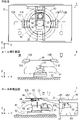
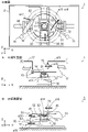
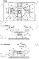
- FIGS. 4 to 15 are schematic diagrams for explaining the schematic operation of the substrate cleaning apparatus 1 of FIG.
- a plan view of substrate cleaning apparatus 1 is shown at the top.
- a side view of the lower holding device 20 and its peripheral portion viewed along the Y direction is shown in the middle row
- a side view of the lower holding device 20 and its peripheral portion seen along the X direction is shown in the lower row.
- the side view in the middle row corresponds to the side view along line AA in FIG. 1
- the side view in the lower row corresponds to the side view along line BB in FIG.
- the scale of some components is different between the upper plan view and the middle and lower side views. . 4 to 15, the cup 61 is indicated by a two-dot chain line, and the outline of the substrate W is indicated by a thick one-dot chain line.
- the shutter 91 of the opening/closing device 90 closes the loading/unloading port 2x.
- the lower chucks 11A and 11B are maintained in a state where the distance between them is sufficiently larger than the diameter of the substrate W, as shown in FIG.
- the upper chucks 12A and 12B are also maintained in a state where the distance between them is sufficiently larger than the diameter of the substrate W. As shown in FIG.
- the movable pedestal 32 of the pedestal device 30 is arranged so that the center of the suction holding portion 21 is positioned at the center of the cup 61 in plan view.
- the undersurface cleaning device 50 is arranged at the approach position.
- the up-and-down support portion 54 of the lower surface cleaning device 50 has a cleaning surface (upper end portion) of the lower surface brush 51 positioned below the suction holding portion 21 .
- the position of the lower surface brush 51 in this initial state is called a standby position.
- the standby position is below the substrate W when the substrate W is held by the suction holding unit 21 .
- the plurality of support pins 41 are positioned below the suction holding portion 21 .
- cup 61 is in the lower cup position.
- the center position of the cup 61 in plan view will be referred to as a plane reference position rp.
- the position of the movable base 32 on the bottom surface portion 2a when the center of the suction holding portion 21 is at the plane reference position rp in plan view is called a first horizontal position.
- a substrate W is carried into the unit housing 2 of the substrate cleaning apparatus 1 .
- the shutter 91 opens the loading/unloading port 2x.
- the hand (substrate holder) RH of the substrate transport robot (not shown) loads the substrate W into the unit housing 2 at a substantially central position through the loading/unloading port 2x.
- the substrate W held by the hand RH is positioned between the lower chuck 11A and upper chuck 12A and the lower chuck 11B and upper chuck 12B, as shown in FIG.
- the lower chucks 11A and 11B approach each other so that the plurality of supporting pieces of the lower chucks 11A and 11B are positioned below the peripheral edge of the lower surface of the substrate W, as indicated by a thick solid arrow a2 in FIG.
- the hand RH descends and exits from the carry-in/carry-out opening 2x.
- a plurality of portions of the peripheral portion of the lower surface of the substrate W held by the hand RH are supported by the plurality of supporting pieces of the lower chucks 11A and 11B.
- the shutter 91 closes the loading/unloading port 2x.
- the upper chucks 12A and 12B approach each other so that the plurality of holding pieces of the upper chucks 12A and 12B come into contact with the outer peripheral edge of the substrate W, as indicated by the thick solid arrow a3 in FIG.
- a plurality of holding pieces of the upper chucks 12A and 12B abut against a plurality of portions of the outer periphery of the substrate W, so that the substrate W supported by the lower chucks 11A and 11B is further held by the upper chucks 12A and 12B.
- the movable pedestal 32 is moved so that the suction holding portion 21 is displaced from the plane reference position rp by a predetermined distance and the center of the lower surface brush 51 is positioned at the plane reference position rp. Move forward from a horizontal position of 1. At this time, the position of the movable pedestal 32 located on the bottom surface portion 2a is called a second horizontal position.
- the lifting support 54 is lifted so that the cleaning surface of the lower surface brush 51 at the standby position contacts the central area of the lower surface of the substrate W.
- the position of the lower surface brush 51 at this time is called a processing position.
- the lower surface brush 51 rotates (rotates) around the vertical axis. As a result, contaminants adhering to the central region of the lower surface of the substrate W are physically removed by the lower surface brush 51 .
- FIG. 7 an enlarged side view of the portion where the lower surface brush 51 contacts the lower surface of the substrate W is shown in a balloon.
- the liquid nozzle 52 and the gas ejection part 53 are held in a position close to the lower surface of the substrate W while the lower surface brush 51 is in contact with the substrate W.
- the liquid nozzle 52 discharges the cleaning liquid toward the lower surface of the substrate W at a position in the vicinity of the lower surface brush 51, as indicated by the outline arrow a51.
- the cleaning liquid supplied to the lower surface of the substrate W from the liquid nozzle 52 is guided to the contact portion between the lower surface brush 51 and the substrate W, so that the contaminants removed from the back surface of the substrate W by the lower surface brush 51 are removed by the cleaning liquid. washed away.
- the liquid nozzle 52 is attached to the lifting support portion 54 together with the undersurface brush 51 .
- the cleaning liquid can be efficiently supplied to the portion of the lower surface of the substrate W to be cleaned by the lower surface brush 51 . Therefore, the consumption of the cleaning liquid is reduced and excessive scattering of the cleaning liquid is suppressed.
- FIG. 7 an enlarged side view of the portion where the lower surface brush 51 contacts the lower surface of the substrate W is shown in a balloon.
- the liquid nozzle 52 and the gas ejection part 53 are held in a position close to the lower surface of the substrate W while the lower surface brush 51 is in contact with the substrate W.
- the liquid nozzle 52 discharges the cleaning liquid toward the lower surface of the substrate W at a position in the vicinity of the lower surface brush 51, as indicated by the outline arrow a51.
- the cleaning liquid supplied to the lower surface of the substrate W from the liquid nozzle 52 is guided to the contact portion between the lower surface brush 51 and the substrate W, so that the contaminants removed from the back surface of the substrate W by the lower surface brush 51 are removed by the cleaning liquid. washed away.
- the liquid nozzle 52 is attached to the lifting support portion 54 together with the undersurface brush 51 .
- the cleaning liquid can be efficiently supplied to the portion of the lower surface of the substrate W to be cleaned by the lower surface brush 51 . Therefore, the consumption of the cleaning liquid is reduced and excessive scattering of the cleaning liquid is suppressed.
- the upper surface 54u of the lifting support portion 54 is inclined downward in the direction away from the suction holding portion 21. As shown in FIG. In this case, when the cleaning liquid containing contaminants falls from the lower surface of the substrate W onto the lift support section 54 , the cleaning liquid received by the upper surface 54 u is guided away from the adsorption holding section 21 .
- the gas ejection portion 53 is positioned between the lower surface brush 51 and the suction holding portion 21 as indicated by the white arrow a52 in the blowout in FIG. A gas is jetted toward the lower surface of the substrate W.
- the gas ejection part 53 is mounted on the elevation support part 54 so that the gas ejection port extends in the X direction.
- a band-shaped gas curtain extending in the X direction is formed between the bottom brush 51 and the suction holding portion 21 .
- the cleaning liquid containing contaminants is prevented from scattering toward the adsorption holding portion 21 . Therefore, when the lower surface of the substrate W is cleaned by the lower surface brush 51, the cleaning liquid containing contaminants is prevented from adhering to the suction holding portion 21, and the suction surface of the suction holding portion 21 is kept clean.
- the gas jetting portion 53 jets the gas obliquely upward toward the lower surface brush 51 as indicated by the white arrow a52.
- the gas ejection part 53 may eject the gas from the gas ejection part 53 toward the lower surface of the substrate W along the Z direction.
- the movable pedestal 32 moves backward so that the suction holding portion 21 is positioned at the plane reference position rp. That is, the movable base 32 moves from the second horizontal position to the first horizontal position.
- the central region of the lower surface of the substrate W is sequentially dried by the gas curtain by continuing the gas jetting from the gas jetting part 53 to the substrate W. As shown in FIG.
- the lift support portion 54 descends so that the cleaning surface of the lower surface brush 51 is positioned below the suction surface (upper end portion) of the suction holding portion 21. .
- the lower surface brush 51 moves to the standby position.
- the upper chucks 12A and 12B move away from each other so that the plurality of holding pieces of the upper chucks 12A and 12B are separated from the outer peripheral edge of the substrate W.
- the substrate W is in a state of being supported by the lower chucks 11A and 11B.
- the pin connecting member 42 rises so that the upper ends of the plurality of support pins 41 are positioned slightly above the lower chucks 11A and 11B. Thereby, the substrate W supported by the lower chucks 11A and 11B is received by the multiple support pins 41 .
- the lower chucks 11A and 11B move away from each other, as indicated by a thick solid arrow a11 in FIG. At this time, the lower chucks 11A and 11B move to positions where they do not overlap the substrate W supported by the plurality of support pins 41 in plan view. As a result, both the upper holding devices 10A and 10B return to their initial states.
- the pin connecting member 42 descends so that the upper end portions of the plurality of support pins 41 are positioned below the suction holding portion 21, as indicated by a thick solid arrow a12 in FIG. Thereby, the substrate W supported on the plurality of support pins 41 is received by the suction holder 21 . In this state, the suction holding part 21 sucks and holds the central region of the lower surface of the substrate W. As shown in FIG. Simultaneously with the descent of the pin connecting member 42 or after the pin connecting member 42 has been lowered, the cup 61 rises from the lower cup position to the upper cup position as indicated by the thick solid arrow a13 in FIG.
- the suction holding portion 21 rotates around the vertical axis (the axial center of the rotation shaft of the suction holding driving portion 22). As a result, the substrate W sucked and held by the suction holding portion 21 rotates in a horizontal posture.
- the rotation support shaft 71 of the upper surface cleaning device 70 rotates and descends.
- the spray nozzle 73 moves to a position above the substrate W as indicated by a thick solid arrow a15 in FIG. descend to In this state, the spray nozzle 73 sprays the mixed fluid of the cleaning liquid and the gas onto the upper surface of the substrate W.
- the rotation support shaft 71 rotates.
- the spray nozzle 73 moves to a position above the rotating substrate W, as indicated by a thick solid-line arrow a16 in FIG.
- the rotation support shaft 81 of the edge cleaning device 80 also rotates and descends.
- the bevel brush 83 moves to a position above the outer peripheral edge of the substrate W, as indicated by a thick solid arrow a17 in FIG.
- the bevel brush 83 descends so that the central portion of the outer peripheral surface of the bevel brush 83 comes into contact with the outer peripheral edge of the substrate W.
- the bevel brush 83 rotates (rotates) around the vertical axis.
- contaminants adhering to the outer peripheral edge of the substrate W are physically removed by the bevel brush 83 .
- the contaminants peeled off from the outer peripheral edge of the substrate W are washed away by the mixed fluid cleaning liquid sprayed onto the substrate W from the spray nozzle 73 .
- the elevating support 54 rises so that the cleaning surface of the lower surface brush 51 at the standby position contacts the outer region of the lower surface of the substrate W.
- the lower surface brush 51 moves to the processing position.
- the lower surface brush 51 rotates (rotates) around the vertical axis.
- the liquid nozzle 52 ejects the cleaning liquid toward the lower surface of the substrate W
- the gas ejector 53 ejects the gas toward the lower surface of the substrate W.
- the entire outer region of the lower surface of the substrate W that is rotated while being sucked and held by the suction holding portion 21 can be cleaned by the lower surface brush 51 .
- the rotating direction of the lower surface brush 51 may be opposite to the rotating direction of the suction holding portion 21 .
- the outer region of the lower surface of the substrate W can be efficiently cleaned.
- the movement support portion 55 may move back and forth between the approach position and the separation position on the movable base 32, as indicated by the thick solid arrow a19 in FIG. . Even in this case, the lower surface brush 51 can clean the entire lower surface outer region of the substrate W that is rotated while being sucked and held by the suction holding unit 21 .
- the spray nozzle 73 moves to a position on one side of the cup 61 (the initial position), as indicated by a thick solid arrow a20.
- the bevel brush 83 moves to the position on the other side of the cup 61 (the position in the initial state), as indicated by the thick solid arrow a21.
- the rotation of the lower surface brush 51 is stopped, and the lift support portion 54 is lowered so that the cleaning surface of the lower surface brush 51 is separated from the substrate W by a predetermined distance.
- the liquid nozzle 52 moves to the standby position.
- the ejection of the cleaning liquid from the liquid nozzle 52 onto the substrate W and the ejection of the gas onto the substrate W from the gas ejection portion 53 are stopped.
- the adsorption holding unit 21 rotates at high speed, so that the cleaning liquid adhering to the substrate W is shaken off, and the entire substrate W is dried.
- the cup 61 descends from the upper cup position to the lower cup position, as indicated by the thick solid arrow a22 in FIG.
- the lower chucks 11A and 11B are moved to a position where the new substrate W can be supported, as indicated by a thick solid-line arrow a23 in FIG. get closer to each other.
- the substrate W is carried out from within the unit housing 2 of the substrate cleaning apparatus 1 .
- the shutter 91 opens the loading/unloading port 2x immediately before the substrate W is unloaded.
- the hand (substrate holder) RH of the substrate transport robot enters the unit housing 2 through the loading/unloading port 2x.
- the hand RH receives the substrate W on the suction holding unit 21 and exits from the loading/unloading port 2x.
- the shutter 91 closes the loading/unloading port 2x.
- FIGS. 16 to 21 are schematic diagrams for explaining the schematic operation of the substrate cleaning apparatus 1 in FIG. As shown in FIG. 16, when cleaning the upper surface of the substrate W in FIG. Moved above center. In this state, a mixed fluid of cleaning liquid and gas is sprayed onto the upper surface of the substrate W from the spray nozzle 73 .
- the degree of contamination of the lower surface outer region of the substrate W is 100% and the degree of contamination of the lower surface brush 51 is 0%.
- the degree of contamination is an index indicating low degree of cleanliness, and high degree of contamination means low degree of cleanliness.
- the spray nozzle 73 is moved outward over the rotating substrate W. As shown in FIG. This movement of the spray nozzle 73 is continued until the spray nozzle 73 reaches above the outer peripheral portion of the substrate W. As shown in FIG. In addition, the lower surface brush 51 is raised from the standby position to the upper processing position while rotating so that the cleaning surface of the lower surface brush 51 contacts the lower surface outer region of the substrate W. As shown in FIG. Furthermore, the cleaning liquid is discharged onto the lower surface of the substrate W from the liquid nozzle 52 of FIG. Thereby, the lower surface outer region of the substrate W is cleaned. When cleaning the outer region of the bottom surface of the substrate W, the gas is jetted toward the bottom surface of the substrate W from the gas ejection part 53 shown in FIG.
- the bottom brush 51 is lowered from the processing position to the standby position while rotating so that the cleaning surface of the bottom brush 51 is separated from the bottom surface outer region of the substrate W.
- the cleaning liquid is discharged from the liquid nozzles 52a toward the center of the cleaning surface of the lower brush 51, and the cleaning liquid is discharged from the liquid nozzles 52b toward the end of the cleaning surface of the lower brush 51. .
- the lower surface brush 51 is cleaned.
- the cleaning liquid discharged to the lower surface brush 51 falls downward due to gravity. In this case, since the cleaning liquid does not scatter around the lower surface brush 51, the cleaning of the substrate W is prevented from being adversely affected.
- the cleaning liquid ejected from the liquid nozzle 52a is supplied to the central portion of the cleaning surface of the lower brush 51 obliquely from above in a parabolic shape. Ultrasonic cleaning may be used in combination for cleaning the lower surface brush 51 .
- the lower surface brush 51 is rotated and raised from the waiting position to the upper processing position so that the cleaning surface of the lower surface brush 51 comes into contact with the outer region of the lower surface of the substrate W.
- the outer lower surface area of the substrate W is cleaned again.
- the cleaning operation of the lower surface outer region of the substrate W in FIG. 19 is the same as the cleaning operation of the lower surface outer region of the substrate W in FIG.
- the lower surface brush 51 is lowered from the processing position to the standby position while rotating so that the cleaning surface of the lower surface brush 51 is separated from the lower surface outer region of the substrate W, thereby cleaning the lower surface. Brush 51 is cleaned again.
- the cleaning operation of the lower surface brush 51 in FIG. 20 is the same as the cleaning operation of the lower surface brush 51 in FIG.
- the cleaning operation of the lower surface outer region of the substrate W in FIG. 19 and the cleaning operation of the lower surface brush 51 in FIG. 20 are repeated.
- contaminants are transferred between the lower surface outer region of the substrate W and the lower surface brush 51 during the cleaning operation of the lower surface outer region of the substrate W.
- FIG. at present, the degree of contamination of the lower surface outer region of the substrate W is higher than the degree of contamination of the lower surface brush 51 . Therefore, the contaminants adhering to the lower surface outer region of the substrate W are substantially transferred to the lower surface brush 51 . As a result, the degree of contamination of the lower surface outer region of the substrate W is reduced.
- the degree of contamination of the lower surface brush 51 increases in the cleaning operation of the lower surface outer region of the substrate W, the degree of contamination of the lower surface brush 51 is reduced by the subsequent cleaning operation of the lower surface brush 51 . Therefore, by repeating the cleaning operation of the lower surface outer region of the substrate W and the cleaning operation of the lower surface brush 51, both the contamination degree of the lower surface outer region of the substrate W and the contamination degree of the lower surface brush 51 can be reduced to 0%. can. Further, since the cleaning operation of the lower surface outer region of the substrate W and the cleaning operation of the lower surface brush 51 are repeated during the cleaning period of the upper surface of the substrate W, the throughput does not decrease.
- the spray nozzle 73 reaches above the outer peripheral portion of the substrate W, as shown in FIG.
- the cleaning of the upper surface of the substrate W is completed by stopping the injection of the mixed fluid from the spray nozzle 73 to the substrate W.
- FIG. Further, the rotation of the lower surface brush 51 is stopped and the lower surface brush 51 is moved to the standby position, thereby completing the cleaning of the lower surface outer region of the substrate W and the cleaning of the lower surface brush 51 .
- the cleaning liquid used for cleaning the lower surface brush 51 is pure water, but the embodiment is not limited to this.
- the cleaning liquid used for cleaning the lower surface brush 51 may be hot water, functional water, weak alkaline water, or chemical solution.
- the cleaning liquid is a chemical solution, the type of chemical solution may be appropriately changed according to the type of contaminant to be removed.
- the liquid nozzles 52a and 52b stop discharging the cleaning liquid when the lower surface brush 51 is at the processing position, but the embodiment is not limited to this.
- the liquid nozzles 52a and 52b may discharge the cleaning liquid even when the lower surface brush 51 is at the processing position, that is, while the outer region of the lower surface of the substrate W is being cleaned.
- the liquid nozzles 52a and 52b may be used as nozzles for discharging the rinse to the lower surface outer region of the substrate W.
- the liquid nozzles 52a and 52b may also eject the cleaning liquid while the lower surface brush 51 moves up and down between the standby position and the processing position.
- the lower surface of the substrate W is cleaned by rotating the lower surface brush 51 and contacting the lower surface of the substrate W at the processing position. Further, even if the mask brush is contaminated by cleaning the lower surface of the substrate W, the cleaning liquid is discharged from the liquid nozzles 52a and 52b to the center and end portions of the rotating lower surface brush 51 at the standby position. According to this configuration, the lower surface brush 51 can be washed as a whole.
- the standby position of the lower brush 51 vertically overlaps the substrate W held by the suction holder 21, even if the lower brush 51 is relatively large, the footprint hardly increases. Therefore, by using the relatively large bottom brush 51, the bottom surface of the substrate W can be cleaned in a short time. Therefore, even if a step of cleaning the lower surface brush 51 is provided, the throughput hardly changes. Thereby, the cleanliness of the lower surface brush 51 can be maintained without lowering the throughput.
- the lower surface brush 51 is supported by an elevating support portion 54, and each of the liquid nozzles 52a and 52b is attached to the elevating support portion 54 in the vicinity of the lower surface brush 51 so that the discharge port of the cleaning liquid faces obliquely upward.
- the lower surface brush 51 can be easily cleaned without hindering the cleaning of the lower surface of the substrate W by the lower surface brush 51 .
- the liquid nozzle 52a discharges the cleaning liquid so that the cleaning liquid is supplied to the central portion of the lower surface brush 51 from obliquely above in a parabolic shape. As a result, the central portion of the lower surface brush 51 can be easily cleaned without hindering the cleaning of the lower surface of the substrate W by the lower surface brush 51 .
- the upper surface of the substrate W is cleaned using the spray nozzle 73, but the embodiment is not limited to this.
- the upper surface of the substrate W may be cleaned using a brush, or may be cleaned using a rinse nozzle that ejects a rinse liquid.
- the upper surface of the substrate W may not be cleaned.
- the substrate cleaning apparatus 1 does not include the upper surface cleaning apparatus 70 .
- the outer peripheral edge of the substrate W may not be cleaned.
- the substrate cleaning device 1 does not include the edge cleaning device 80 .
- the substrate cleaning apparatus 1 includes the control device 9, but the embodiment is not limited to this. If the substrate cleaning apparatus 1 is configured to be controllable by an external information processing device, the substrate cleaning apparatus 1 may not include the control device 9 .
- the substrate W is an example of the substrate
- the suction holding portion 21 is an example of the substrate holding portion
- the lower surface brush 51 is an example of the lower surface brush
- the liquid nozzles 52a and 52b are the first and second liquid nozzles 52a and 52b, respectively. It is an example of the second liquid nozzle
- the substrate cleaning apparatus 1 is an example of the substrate cleaning apparatus
- the elevating support section 54 is an example of the support section.
Landscapes
- Cleaning Or Drying Semiconductors (AREA)
Priority Applications (3)
| Application Number | Priority Date | Filing Date | Title |
|---|---|---|---|
| KR1020247003898A KR102825486B1 (ko) | 2021-07-15 | 2022-06-30 | 기판 세정 장치 |
| CN202280049929.6A CN117642846A (zh) | 2021-07-15 | 2022-06-30 | 基板清洗装置 |
| US18/579,208 US12463063B2 (en) | 2021-07-15 | 2022-06-30 | Substrate cleaning device |
Applications Claiming Priority (2)
| Application Number | Priority Date | Filing Date | Title |
|---|---|---|---|
| JP2021117423A JP7810528B2 (ja) | 2021-07-15 | 2021-07-15 | 基板洗浄装置 |
| JP2021-117423 | 2021-07-15 |
Publications (1)
| Publication Number | Publication Date |
|---|---|
| WO2023286635A1 true WO2023286635A1 (ja) | 2023-01-19 |
Family
ID=84920207
Family Applications (1)
| Application Number | Title | Priority Date | Filing Date |
|---|---|---|---|
| PCT/JP2022/026392 Ceased WO2023286635A1 (ja) | 2021-07-15 | 2022-06-30 | 基板洗浄装置 |
Country Status (6)
| Country | Link |
|---|---|
| US (1) | US12463063B2 (https=) |
| JP (1) | JP7810528B2 (https=) |
| KR (1) | KR102825486B1 (https=) |
| CN (1) | CN117642846A (https=) |
| TW (2) | TWI850692B (https=) |
| WO (1) | WO2023286635A1 (https=) |
Cited By (1)
| Publication number | Priority date | Publication date | Assignee | Title |
|---|---|---|---|---|
| CN118268297A (zh) * | 2024-06-03 | 2024-07-02 | 沈阳和研科技股份有限公司 | 一种陶瓷吸盘清洁装置及划片机 |
Families Citing this family (3)
| Publication number | Priority date | Publication date | Assignee | Title |
|---|---|---|---|---|
| JP7810528B2 (ja) | 2021-07-15 | 2026-02-03 | 株式会社Screenホールディングス | 基板洗浄装置 |
| CN118635188B (zh) * | 2024-08-13 | 2024-11-05 | 河南新黄水电工程有限公司辉县百泉分公司 | 一种水利工程施工设备的刷洗机构 |
| CN118831879B (zh) * | 2024-09-24 | 2025-01-24 | 洛阳合兴工贸有限公司 | 一种汽车连杆加工用清洁装置 |
Citations (7)
| Publication number | Priority date | Publication date | Assignee | Title |
|---|---|---|---|---|
| JPH06120184A (ja) * | 1992-10-02 | 1994-04-28 | Tokyo Electron Ltd | 洗浄装置 |
| JP2003332287A (ja) * | 2002-05-17 | 2003-11-21 | Dainippon Screen Mfg Co Ltd | 基板洗浄方法及びその装置 |
| JP2017034235A (ja) * | 2015-07-29 | 2017-02-09 | 東京エレクトロン株式会社 | 基板処理装置、基板処理方法および記憶媒体 |
| JP2019145687A (ja) * | 2018-02-21 | 2019-08-29 | 東京エレクトロン株式会社 | 洗浄具、基板洗浄装置及び基板洗浄方法 |
| JP2020017689A (ja) * | 2018-07-27 | 2020-01-30 | 芝浦メカトロニクス株式会社 | 基板洗浄装置及び基板洗浄方法 |
| WO2021053995A1 (ja) * | 2019-09-17 | 2021-03-25 | 株式会社Screenホールディングス | 基板洗浄装置 |
| JP2021093427A (ja) * | 2019-12-09 | 2021-06-17 | 株式会社Screenホールディングス | 基板洗浄装置および基板洗浄方法 |
Family Cites Families (2)
| Publication number | Priority date | Publication date | Assignee | Title |
|---|---|---|---|---|
| JP5904169B2 (ja) | 2013-07-23 | 2016-04-13 | 東京エレクトロン株式会社 | 基板洗浄装置、基板洗浄方法及び記憶媒体 |
| JP7810528B2 (ja) | 2021-07-15 | 2026-02-03 | 株式会社Screenホールディングス | 基板洗浄装置 |
-
2021
- 2021-07-15 JP JP2021117423A patent/JP7810528B2/ja active Active
-
2022
- 2022-06-30 US US18/579,208 patent/US12463063B2/en active Active
- 2022-06-30 KR KR1020247003898A patent/KR102825486B1/ko active Active
- 2022-06-30 CN CN202280049929.6A patent/CN117642846A/zh active Pending
- 2022-06-30 WO PCT/JP2022/026392 patent/WO2023286635A1/ja not_active Ceased
- 2022-07-04 TW TW111124911A patent/TWI850692B/zh active
- 2022-07-04 TW TW113130596A patent/TW202447827A/zh unknown
Patent Citations (7)
| Publication number | Priority date | Publication date | Assignee | Title |
|---|---|---|---|---|
| JPH06120184A (ja) * | 1992-10-02 | 1994-04-28 | Tokyo Electron Ltd | 洗浄装置 |
| JP2003332287A (ja) * | 2002-05-17 | 2003-11-21 | Dainippon Screen Mfg Co Ltd | 基板洗浄方法及びその装置 |
| JP2017034235A (ja) * | 2015-07-29 | 2017-02-09 | 東京エレクトロン株式会社 | 基板処理装置、基板処理方法および記憶媒体 |
| JP2019145687A (ja) * | 2018-02-21 | 2019-08-29 | 東京エレクトロン株式会社 | 洗浄具、基板洗浄装置及び基板洗浄方法 |
| JP2020017689A (ja) * | 2018-07-27 | 2020-01-30 | 芝浦メカトロニクス株式会社 | 基板洗浄装置及び基板洗浄方法 |
| WO2021053995A1 (ja) * | 2019-09-17 | 2021-03-25 | 株式会社Screenホールディングス | 基板洗浄装置 |
| JP2021093427A (ja) * | 2019-12-09 | 2021-06-17 | 株式会社Screenホールディングス | 基板洗浄装置および基板洗浄方法 |
Cited By (1)
| Publication number | Priority date | Publication date | Assignee | Title |
|---|---|---|---|---|
| CN118268297A (zh) * | 2024-06-03 | 2024-07-02 | 沈阳和研科技股份有限公司 | 一种陶瓷吸盘清洁装置及划片机 |
Also Published As
| Publication number | Publication date |
|---|---|
| US12463063B2 (en) | 2025-11-04 |
| US20240321598A1 (en) | 2024-09-26 |
| KR102825486B1 (ko) | 2025-06-30 |
| KR20240029067A (ko) | 2024-03-05 |
| TWI850692B (zh) | 2024-08-01 |
| JP2023013332A (ja) | 2023-01-26 |
| JP7810528B2 (ja) | 2026-02-03 |
| CN117642846A (zh) | 2024-03-01 |
| TW202318479A (zh) | 2023-05-01 |
| TW202447827A (zh) | 2024-12-01 |
Similar Documents
| Publication | Publication Date | Title |
|---|---|---|
| WO2023286635A1 (ja) | 基板洗浄装置 | |
| JP7623226B2 (ja) | 基板洗浄装置および基板洗浄方法 | |
| JP7564693B2 (ja) | 下面ブラシ、ブラシユニットおよび基板洗浄装置 | |
| KR102678565B1 (ko) | 기판 세정 장치 및 기판 세정 방법 | |
| JP2022189495A (ja) | 基板洗浄装置 | |
| KR102853110B1 (ko) | 하면 브러시, 브러시 유닛 및 기판 세정 장치 | |
| KR102667273B1 (ko) | 기판 세정 장치 및 기판 세정 방법 | |
| JP7587608B2 (ja) | 基板処理装置および基板処理方法 | |
| JP7589266B2 (ja) | 基板処理装置および基板処理方法 | |
| JP7591024B2 (ja) | 基板処理装置および基板処理方法 | |
| JP7598919B2 (ja) | 基板処理装置および基板処理方法 | |
| KR102849152B1 (ko) | 기판 처리 장치 및 기판 처리 방법 | |
| JP7672908B2 (ja) | 基板洗浄装置および基板洗浄方法 | |
| JP7491805B2 (ja) | 基板洗浄装置および基板洗浄方法 |
Legal Events
| Date | Code | Title | Description |
|---|---|---|---|
| 121 | Ep: the epo has been informed by wipo that ep was designated in this application |
Ref document number: 22841979 Country of ref document: EP Kind code of ref document: A1 |
|
| WWE | Wipo information: entry into national phase |
Ref document number: 18579208 Country of ref document: US |
|
| WWE | Wipo information: entry into national phase |
Ref document number: 202280049929.6 Country of ref document: CN |
|
| ENP | Entry into the national phase |
Ref document number: 20247003898 Country of ref document: KR Kind code of ref document: A |
|
| WWE | Wipo information: entry into national phase |
Ref document number: 1020247003898 Country of ref document: KR |
|
| NENP | Non-entry into the national phase |
Ref country code: DE |
|
| 122 | Ep: pct application non-entry in european phase |
Ref document number: 22841979 Country of ref document: EP Kind code of ref document: A1 |
|
| WWG | Wipo information: grant in national office |
Ref document number: 18579208 Country of ref document: US |