WO2023286400A1 - 電気化学測定装置及び電気化学測定方法 - Google Patents
電気化学測定装置及び電気化学測定方法 Download PDFInfo
- Publication number
- WO2023286400A1 WO2023286400A1 PCT/JP2022/016475 JP2022016475W WO2023286400A1 WO 2023286400 A1 WO2023286400 A1 WO 2023286400A1 JP 2022016475 W JP2022016475 W JP 2022016475W WO 2023286400 A1 WO2023286400 A1 WO 2023286400A1
- Authority
- WO
- WIPO (PCT)
- Prior art keywords
- channel
- liquid
- working electrode
- counter electrode
- sample liquid
- Prior art date
- Legal status (The legal status is an assumption and is not a legal conclusion. Google has not performed a legal analysis and makes no representation as to the accuracy of the status listed.)
- Ceased
Links
Images



Classifications
-
- G—PHYSICS
- G01—MEASURING; TESTING
- G01N—INVESTIGATING OR ANALYSING MATERIALS BY DETERMINING THEIR CHEMICAL OR PHYSICAL PROPERTIES
- G01N27/00—Investigating or analysing materials by the use of electric, electrochemical, or magnetic means
- G01N27/26—Investigating or analysing materials by the use of electric, electrochemical, or magnetic means by investigating electrochemical variables; by using electrolysis or electrophoresis
- G01N27/28—Electrolytic cell components
Definitions
- the present invention relates to an electrochemical measuring device and an electrochemical measuring method.
- Patent Document 1 As an apparatus for measuring the chlorine concentration in a cleaning solution with high accuracy, for example, as shown in Patent Document 1, a flow injection type electrochemical system that performs voltammetry measurement in which a sample is analyzed by applying a voltage to a sample solution that is an electrolyte solution is used.
- a device is known (for example, US Pat. In this device, a cleaning solution, which is a sample solution, is sent to a measuring cell equipped with a working electrode, a reference electrode and a counter electrode, and a predetermined voltage is applied to the working electrode to measure the chlorine concentration in the sample solution. be able to.
- the present invention has been made to solve such problems at once, and is mainly intended to reduce the retention of bubbles generated at the working electrode while reducing the influence of electromagnetic noise in an electrochemical measurement device. This is an issue.
- an electrochemical measuring apparatus electrochemically measures the concentration of a substance to be measured contained in a sample liquid, and comprises a channel through which the sample liquid flows, and the sample flowing through the channel.
- a working electrode and a counter electrode having liquid-contacting surfaces in contact with a liquid, wherein the liquid-contacting surface of the working electrode and the liquid-contacting surface of the counter electrode are displaced from each other along the direction in which the channel extends, and It is characterized by being arranged so that a part faces directly.
- the working electrode and the counter electrode are brought close to each other so that parts of their wetted surfaces face each other. noise can be reduced.
- the liquid contact surface of the working electrode and the liquid contact surface of the counter electrode are arranged so as to be offset from each other along the direction in which the flow channel extends while partly facing each other, the flow of the sample liquid is disturbed. can be generated, and bubbles generated on the wetted surface of the working electrode can be discharged downstream without remaining.
- the inner wall surface forming the flow path has concave portions at positions respectively corresponding to the counter electrode and the working electrode. and the bottom surface of each of the recesses is constituted by the liquid contact surfaces of the working electrode and the counter electrode.
- the electrochemical measurement device includes a measurement channel portion in which the channel faces the liquid contact surface of the working electrode and the liquid contact surface of the counter electrode, and the measurement channel portion It is preferable that the sample liquid is applied perpendicularly or obliquely from the upstream side to the downstream side to the liquid-contacting surface of the counter electrode disposed on the downstream side. If the measurement channel section is formed in this way, by applying the sample liquid perpendicularly or obliquely to the wetted surface of the electrode on the downstream side, the bubbles accumulated on the wetted surface of the electrode on the downstream side can be effectively removed. It can be pushed away well.
- the channel is preferably formed so that the sample liquid is applied perpendicularly or obliquely to the liquid-contacting surface of the working electrode. In this way, the flow of the sample liquid collides with the wetted surface of the working electrode, which tends to cause turbulent flow. Makes it easier to remove air bubbles.
- the electrochemical measurement device is formed such that the sample liquid flows upward in the measurement flow path, and the working electrode It is preferable that the contact surface of the counter electrode and the contact surface of the counter electrode are displaced vertically along the measurement channel.
- the electrochemical measurement device further includes a fluid blocking part capable of blocking the flow of the sample liquid upstream of the working electrode and the counter electrode in the channel, and the fluid blocking part blocks the flow of the sample liquid. It is preferable that the concentration of the substance to be measured contained in the sample liquid is electrochemically measured in this state. In this way, by blocking the flow of the sample liquid during measurement, it is possible to block external electromagnetic noise transmitted through the sample liquid, thereby improving the measurement accuracy.
- a roller pump, a diaphragm pump, or an on-off valve is mentioned as a specific aspect of such a fluid shutoff part.
- the electrochemical measurement device is provided with a second counter electrode upstream of the working electrode and the counter electrode in the channel.
- the electromagnetic noise transmitted through the sample liquid is absorbed by the second counter electrode, thereby reducing the influence of the electromagnetic noise transmitted to the working electrode and the counter electrode on the downstream side.
- the working electrode and the counter electrode are preferably arranged in this order from upstream.
- the counter electrode can absorb the electromagnetic noise transmitted from the downstream side of the working electrode through the sample liquid, so that the measurement accuracy can be further improved.
- the electrochemical measurement method of the present invention uses an electrochemical measurement device comprising a channel through which a sample liquid flows, and a working electrode and a counter electrode each having a wetted surface contacting the sample liquid flowing through the channel.
- An electrochemical measurement method for electrochemically measuring the concentration of a substance to be measured contained in a liquid wherein the liquid contact surface of the working electrode and the liquid contact surface of the counter electrode are arranged along the direction in which the channel extends. are arranged such that they are offset from each other and some of them face each other. According to such an electrochemical measurement method, the same effect as the electrochemical measurement device of the present invention described above can be obtained.
- FIG. 1 is a diagram showing the overall configuration of an electrochemical measuring device according to one embodiment of the present invention
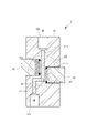
- FIG. 3 is an enlarged view of part A in FIG. 2
- FIG. 2 is a functional block diagram of the electrochemical measurement device of the same embodiment
- the figure which shows roughly the structure of the measuring cell of the electrochemical measuring apparatus of other embodiment The figure which shows roughly the structure of the measuring cell of the electrochemical measuring apparatus of other embodiment.
- An electrochemical measurement device 100 according to one embodiment of the present invention will be described below with reference to the drawings.
- the electrochemical measurement device 100 of the present embodiment is, for example, a flow injection type electrochemical measurement device 100 that performs triode voltammetry measurement in which a sample is analyzed by applying a voltage to a sample liquid that is an electrolyte solution.
- the electrochemical measurement apparatus 100 can be used for various purposes. Here, it is connected to a flow path (also referred to as a main flow path ML) in which a cleaning liquid used to wash foods such as vegetables flows, and the water contained in the cleaning liquid is connected to the flow path. It is configured to measure the concentration of residual chlorine (which is the substance to be measured) in the Residual chlorine refers to all available chlorine contained in the aqueous solution. And this available chlorine includes free chlorine such as hypochlorous acid (HClO), hypochlorite ion (ClO ⁇ ), dissolved chlorine (Cl 2 ), monochloramine (NH 2 Cl) and dichloramine (NHCl 2 ). , and trichloramine (NCl 3 ).
- the electrochemical measurement apparatus 100 includes a box-shaped casing 1 having side walls provided with an inlet port P1 and an outlet port P2, and both ends of the casing 1 having an inlet port P1 and an outlet port P1.
- a sample flow path 2 connected to the port P2 to flow the sample liquid introduced from the inlet port P1 and lead to the outlet port P2, a sensor section 3 provided on the sample flow path 2, and a signal from the sensor section 3. and an information processing device 5 for calculating the concentration of components in the sample based on the voltage, current, etc. obtained by the measurement circuit 4 .
- the inlet port P1 is connected to a first branch pipe forming a first branch channel BL1 branching from the main channel ML, and the outlet port P2 forming a second branch channel BL2 branching from the main channel ML. It is connected to the second branch pipe.
- the sample liquid flowing through the main channel ML passes through the first branch channel BL1 and is taken into the sample channel 2 via the inlet port P1. It is returned to the main flow path ML through the branch flow path BL2.
- the sample flow path 2 includes an inlet flow path 21 that guides the sample liquid introduced from the inlet port P1 to the sensor section 3, a sensor flow path 22 provided in the sensor section 3, and an outlet port P2 that transfers the sample liquid exiting the sensor section 3. and an outlet channel 23 leading to the
- the upstream end of sensor channel 22 is connected to the downstream end of inlet channel 21 , and the downstream end of sensor channel 22 is connected to the upstream end of outlet channel 23 .
- the sensor unit 3 includes a measurement cell 31 having a sensor channel 22 formed therein, a working electrode 32 attached to the measurement cell 31 and having a liquid-contact surface that contacts the sample liquid flowing through the sensor channel 22, and a reference electrode 33. and a counter electrode 34 .
- a reference electrode 33, a working electrode 32, and a counter electrode 34 are provided in this order from upstream.
- the measurement cell 31 is, for example, of a flow cell type having a block shape as shown in FIGS.
- This sensor flow path 22 is formed by the inner wall of a tubular through-hole 311 passing through the measurement cell 31 .
- An upstream end of the sensor channel 22 communicates with an inlet 22a formed on one end face of the measurement cell 31, and a downstream end of the sensor channel 22 communicates with an outlet port 22b formed on the other end face of the measurement cell 31. communicates with The inlet port 22 a is connected to the downstream end of the inlet channel 21 and the outlet port 22 b is connected to the upstream end of the outlet channel 23 .
- the introduction port 22 a is formed on the bottom surface of the measurement cell 31 and the outlet port 22 b is formed on the top surface of the measurement cell 31 .
- the sample liquid introduced from the inlet 22a flows through the sensor channel 22 from the bottom to the top (upward) and is discharged from the outlet 22b.
- the sensor channel 22 includes an introduction channel portion 221 whose upstream end is connected to the inlet port 22a, and a measurement sensor provided downstream of the introduction channel portion 221 and facing the liquid contact surface 321 of the working electrode 32. and a channel portion 222 .
- the downstream end of this measurement channel section 222 is connected to the outlet 22b.
- the working electrode 32 has a sensor surface (liquid contact surface) 321 for detecting the object to be measured by applying a voltage in contact with the sample liquid.
- the working electrode 32 is, for example, a diamond electrode in which the sensor surface 321 is formed of boron-doped diamond having conductivity by doping boron at a high concentration.
- the reference electrode 33 is an electrode that serves as a reference for the potential of the working electrode 32, and in this embodiment, a silver/silver chloride electrode is used.
- the counter electrode 34 allows current to flow through the working electrode 32 without hindrance when setting a certain potential on the working electrode 32 . Similar to the working electrode 32, this embodiment uses a boron-doped diamond electrode.
- the measurement cell 31 has a plurality of thin portions 312 whose thickness is relatively smaller than that of other portions. 313 are formed.
- Each of the electrodes 32, 33, 34 is attached to the thin portion 312 so that the liquid contact surfaces 321, 331, 341 of the electrodes 32, 33, 34 cover the opening 313 from the outside.
- Sealing members S such as O-rings and gaskets are interposed between the liquid contact surfaces 321, 331, 341 of the electrodes 32, 33, 34 and the outer wall surface of the thin portion 312, and the gap between them is watertight. Sealed.
- a fluid blocking section 6 capable of blocking the flow of the sample liquid is provided upstream of the sensor section 3 in the sample channel 2 (specifically, the inlet channel 21).
- the fluid blocker 6 of this embodiment is a roller pump (tubing pump). When the roller pump is driven, the sample liquid flows through the inlet channel 21 to the sensor section 3, and when the roller pump is stopped, the flow of the sample liquid in the inlet channel 21 is interrupted, and the sample liquid is sent to the sensor section 3. is set to stop.
- the measurement circuit 4 applies a voltage to the working electrode 32, the reference electrode 33 and the counter electrode 34 and detects the current value at the applied voltage, and includes, for example, a potentiostat.
- the information processing device 5 is a dedicated or general-purpose computer equipped with a CPU, internal memory, input/output interface, A/D converter, and the like. Based on a predetermined program stored in the internal memory, the information processing device 5 controls the voltage applied to the measuring circuit 4 as shown in FIG. A section 51 obtains a current-residual chlorine concentration curve from the relationship between the current signal output from the measuring circuit 4 and the residual chlorine concentration, and calculates the concentration of residual chlorine in the sample based on this current-residual chlorine concentration curve. It functions as a fluid control unit 53 that controls the unit 52 and the fluid cutoff unit 6 .
- the voltage control unit 51 applies a voltage to the measurement circuit 4 while the flow of the sample liquid is blocked by the fluid blocking unit 6 and the liquid supply to the sensor unit 3 is stopped.
- the calculating unit 52 is configured to calculate the concentration of residual chlorine.
- the liquid contact surface 321 of the working electrode 32 and the liquid contact surface 341 of the counter electrode 34 are displaced from each other along the direction in which the sensor channel 22 extends, and they are are arranged to face each other.
- both the working electrode 32 and the counter electrode 34 are provided so that the liquid contact surfaces 321 and 341 thereof face the measurement channel section 222, and the liquid contact surface 321 of the working electrode 32 and the counter electrode 34 are opposed to each other with the measurement flow path section 222 interposed therebetween.
- the measurement channel portion 222 is formed so that the sample liquid flows upward. are placed.
- the working electrode 32 is arranged below (upstream) and the counter electrode 34 is arranged above (downstream).
- recesses 22r are formed at positions corresponding to the counter electrode 34 and the working electrode 32 on the inner wall surface forming the measurement flow channel portion 222 .
- the bottom surface of each concave portion 22r is formed by the liquid contact surfaces 321 and 341 of the corresponding electrodes 32 and 34, respectively.
- the bottom surfaces of the recesses 22r are displaced along the direction in which the measurement flow path section 222 extends, and are arranged such that they partially face each other (partially overlap and face each other). ing.
- part of the liquid contact surface 321 and the liquid contact surface 341 face each other means that part of the liquid contact surfaces 321 and 341 face each other with the measurement flow path part 222 interposed therebetween.
- the one surface 321 and the other surface 341 may be parallel to each other or may be inclined to each other.
- the sample liquid does not flow straight upward in the measurement channel section 222, but flows upward while meandering. Further, in the measurement flow path section 222, the sample liquid can be obliquely applied to the liquid contact surface 341 of the counter electrode 34 from the upstream side to the downstream side. As a result, a turbulent flow of the sample liquid is generated in the vicinity of the liquid contact surfaces 321 and 341 of the working electrode 32 and the counter electrode 34, and air bubbles generated on the sensor surface 321 are not accumulated and are efficiently flushed toward the outlet 22b. be able to.
- the introduction channel portion 221 of the present embodiment is formed so that the sample liquid taken in from the introduction port 22a is directed vertically (including an angle close to the vertical) or obliquely to the liquid contact surface 321 of the working electrode 32. ing.
- the introduction channel part 221 is formed so that the sample liquid taken in from the introduction port 22 a first flows upward, and then changes direction so that the liquid flows sideways, and the sample liquid hits the liquid contact surface 321 of the working electrode 32 . ing.
- the introduction channel part 221 By forming the introduction channel part 221 into such a shape, the flow of the sample liquid that collides with the liquid contact surface 321 of the working electrode 32 becomes turbulent, and bubbles generated on the liquid contact surface 321 can be efficiently washed away. . As a result, measurement accuracy can be further improved.
- the working electrode 32 and the counter electrode 34 are brought close to each other so that part of the respective wetted surfaces 321 and 341 face each other.
- the influence of external electromagnetic noise transmitted to the electrodes 32 and 34 through the sample liquid can be reduced.
- the liquid contact surface 321 of the working electrode 32 and the liquid contact surface 341 of the counter electrode 34 are arranged so as to be offset from each other along the direction in which the flow channel extends while partly facing each other. turbulence is generated in the flow of the working electrode 32, and air bubbles generated on the wetted surface 321 of the working electrode 32 can be discharged downstream without remaining.
- the present invention is not limited to the above embodiments.
- the fluid cutoff part 6 in the above embodiment was a roller pump, it is not limited to this.
- the fluid blocker 6 of other embodiments may be any device as long as it can completely block the flow of the sample liquid flowing through the introduction channel, and may be, for example, a diaphragm pump or an on-off valve.
- the electrochemical measurement device 100 of another embodiment may not include the fluid blocker 6 on the sample channel 2 .
- the electrochemical measurement device 100 of another embodiment may include a second counter electrode 3435 upstream of the working electrode 32 and the counter electrode 34 in the sensor channel 22, as shown in FIG.
- a boron-doped diamond electrode may be used as the second counter electrode 3435 in the same manner as the counter electrode 34 on the downstream side.
- the second counter electrode 35 may be attached to the measurement cell 31 so that its wetted surface is in contact with the sample liquid flowing through the introduction channel section 221 .
- the introduction channel part 221 is formed so that the sample liquid taken in from the introduction port 22a is applied vertically or obliquely toward the liquid contact surface 321 of the working electrode 32.
- the introduction channel part 221 may be formed so as to extend straight from bottom to top.
- the sample liquid is applied obliquely from the upstream side to the downstream side to the liquid contact surface 341 of the counter electrode 34 in the measurement channel section 222. It is not limited to this.
- the measurement flow channel section 222 directs the sample liquid vertically (at an angle close to the vertical) to the liquid contact surface 341 of the counter electrode 34 from the upstream side to the downstream side. including).
- the working electrode 32 was provided so as to be located upstream of the counter electrode 34, but the present invention is not limited to this. In other embodiments, the counter electrode 34 may be provided upstream of the working electrode 32 .
- the electrochemical measurement device 100 of the above embodiment is of a three-electrode type, it is not limited to this.
- Other embodiments of the electrochemical measurement device 100 may be bipolar, quadrupolar, hexapolar, or the like.
- the working electrode 32 is not limited to the boron-doped diamond electrode, but may be a conductive diamond electrode doped with a Group 13 or Group 15 element such as nitrogen or phosphorus.
- the working electrode 32 is not limited to a diamond electrode, and carbon electrodes containing carbon such as carbon electrodes, glassy carbon electrodes, diamond-like carbon electrodes, etc., noble metals such as gold and platinum, and alloys containing these noble metals are used. It may be an electrode or the like.
- the reference electrode 33 in other embodiments is not limited to a silver/silver chloride electrode, and may be, for example, a standard hydrogen electrode, a mercury/mercury chloride electrode, a hydrogen palladium electrode, or the like.
- the counter electrode of other embodiments is not limited to the diamond electrode, and may be, for example, carbon, stainless steel, gold, silver, silver chloride, platinum, SnO 2 or the like.
- the substance to be measured in other embodiments is not limited to the residual chlorine described above, and may be other inorganic substances such as ozone, bromine, and hydrogen peroxide.
- the electrochemical measurement device 100 of another embodiment is not limited to the food field, but can be used for tap water, drinking water, water of rivers and marshes, industrial wastewater, industrial wastewater, laboratory reagents, night soil, sewage and sewage, medical reagents, It may be used for various sample solutions such as cooling water for air conditioning and leachate treatment.
- Electrochemical measuring apparatus 22 Sensor channel 32
- Working electrode 321 Wetted surface (sensor surface) 34
- Counter electrode 341 Wetted surface
Landscapes
- Chemical & Material Sciences (AREA)
- Life Sciences & Earth Sciences (AREA)
- Health & Medical Sciences (AREA)
- Physics & Mathematics (AREA)
- Chemical Kinetics & Catalysis (AREA)
- Electrochemistry (AREA)
- Molecular Biology (AREA)
- Analytical Chemistry (AREA)
- Biochemistry (AREA)
- General Health & Medical Sciences (AREA)
- General Physics & Mathematics (AREA)
- Immunology (AREA)
- Pathology (AREA)
- Automatic Analysis And Handling Materials Therefor (AREA)
Priority Applications (1)
| Application Number | Priority Date | Filing Date | Title |
|---|---|---|---|
| JP2023535136A JP7825622B2 (ja) | 2021-07-16 | 2022-03-31 | 電気化学測定装置及び電気化学測定方法 |
Applications Claiming Priority (2)
| Application Number | Priority Date | Filing Date | Title |
|---|---|---|---|
| JP2021118194 | 2021-07-16 | ||
| JP2021-118194 | 2021-07-16 |
Publications (1)
| Publication Number | Publication Date |
|---|---|
| WO2023286400A1 true WO2023286400A1 (ja) | 2023-01-19 |
Family
ID=84919317
Family Applications (1)
| Application Number | Title | Priority Date | Filing Date |
|---|---|---|---|
| PCT/JP2022/016475 Ceased WO2023286400A1 (ja) | 2021-07-16 | 2022-03-31 | 電気化学測定装置及び電気化学測定方法 |
Country Status (2)
| Country | Link |
|---|---|
| JP (1) | JP7825622B2 (https=) |
| WO (1) | WO2023286400A1 (https=) |
Cited By (2)
| Publication number | Priority date | Publication date | Assignee | Title |
|---|---|---|---|---|
| CN116223361A (zh) * | 2023-02-17 | 2023-06-06 | 星氢源(上海)科技有限公司 | 一种电化学测试装置 |
| JP7322311B1 (ja) | 2023-02-28 | 2023-08-07 | 住友化学株式会社 | 電気化学センサおよび電気化学センサの製造方法 |
Citations (8)
| Publication number | Priority date | Publication date | Assignee | Title |
|---|---|---|---|---|
| JPS58155081A (ja) * | 1982-03-12 | 1983-09-14 | Matsushita Electric Ind Co Ltd | 酵素反応測定セル |
| JPS6224141A (ja) * | 1985-07-25 | 1987-02-02 | Matsushita Electric Works Ltd | 化学物質検出器 |
| JPH0265156U (https=) * | 1988-11-04 | 1990-05-16 | ||
| JPH0390073U (https=) * | 1989-12-29 | 1991-09-13 | ||
| JP2001174431A (ja) * | 1999-12-21 | 2001-06-29 | Matsushita Electric Ind Co Ltd | 酸性液中の残留塩素濃度測定装置及び測定方法 |
| JP2001235446A (ja) * | 2000-02-24 | 2001-08-31 | Hitachi Ltd | 残留塩素計 |
| JP2003057230A (ja) * | 2001-08-10 | 2003-02-26 | Yokogawa Electric Corp | 水質計測器 |
| JP2007139725A (ja) * | 2005-11-22 | 2007-06-07 | Keio Gijuku | 残留塩素測定方法及び残留塩素測定装置 |
-
2022
- 2022-03-31 WO PCT/JP2022/016475 patent/WO2023286400A1/ja not_active Ceased
- 2022-03-31 JP JP2023535136A patent/JP7825622B2/ja active Active
Patent Citations (8)
| Publication number | Priority date | Publication date | Assignee | Title |
|---|---|---|---|---|
| JPS58155081A (ja) * | 1982-03-12 | 1983-09-14 | Matsushita Electric Ind Co Ltd | 酵素反応測定セル |
| JPS6224141A (ja) * | 1985-07-25 | 1987-02-02 | Matsushita Electric Works Ltd | 化学物質検出器 |
| JPH0265156U (https=) * | 1988-11-04 | 1990-05-16 | ||
| JPH0390073U (https=) * | 1989-12-29 | 1991-09-13 | ||
| JP2001174431A (ja) * | 1999-12-21 | 2001-06-29 | Matsushita Electric Ind Co Ltd | 酸性液中の残留塩素濃度測定装置及び測定方法 |
| JP2001235446A (ja) * | 2000-02-24 | 2001-08-31 | Hitachi Ltd | 残留塩素計 |
| JP2003057230A (ja) * | 2001-08-10 | 2003-02-26 | Yokogawa Electric Corp | 水質計測器 |
| JP2007139725A (ja) * | 2005-11-22 | 2007-06-07 | Keio Gijuku | 残留塩素測定方法及び残留塩素測定装置 |
Cited By (3)
| Publication number | Priority date | Publication date | Assignee | Title |
|---|---|---|---|---|
| CN116223361A (zh) * | 2023-02-17 | 2023-06-06 | 星氢源(上海)科技有限公司 | 一种电化学测试装置 |
| JP7322311B1 (ja) | 2023-02-28 | 2023-08-07 | 住友化学株式会社 | 電気化学センサおよび電気化学センサの製造方法 |
| JP2024122112A (ja) * | 2023-02-28 | 2024-09-09 | 住友化学株式会社 | 電気化学センサおよび電気化学センサの製造方法 |
Also Published As
| Publication number | Publication date |
|---|---|
| JPWO2023286400A1 (https=) | 2023-01-19 |
| JP7825622B2 (ja) | 2026-03-06 |
Similar Documents
| Publication | Publication Date | Title |
|---|---|---|
| US5364510A (en) | Scheme for bath chemistry measurement and control for improved semiconductor wet processing | |
| US9207204B2 (en) | Method and apparatus for determining information concerning presence of constituents of a liquid sample with oxygen demand | |
| WO2023286400A1 (ja) | 電気化学測定装置及び電気化学測定方法 | |
| US20070114137A1 (en) | Residual chlorine measuring method and residual chlorine measuring device | |
| JP2015090286A (ja) | 化学的酸素消費量(cod)自動測定装置 | |
| JP2013152146A (ja) | 水質検査装置及び水質検査方法 | |
| Jin et al. | A miniaturized FIA system for the determination of residual chlorine in environmental water samples | |
| JP7227714B2 (ja) | 電気化学測定装置及びその洗浄方法 | |
| JP7572308B2 (ja) | 電気化学測定装置及び電気化学測定方法 | |
| US20210033590A1 (en) | Method for determining a chemical intake capacity of a process medium in a measuring point and measuring point for determining a chemical intake capacity of a process medium | |
| JP7702850B2 (ja) | 電気化学測定装置及び電気化学測定方法 | |
| JP2003043007A (ja) | 電気化学的水質測定器及びこれを備えた水処理装置 | |
| JP2001174430A (ja) | 次亜塩素酸濃度及びpH測定用複合センサー | |
| US6652721B2 (en) | Sensor for determination of O2 concentration in liquids | |
| JP3533573B1 (ja) | 塩素濃度自動測定装置及び塩素濃度測定方法 | |
| KR100759531B1 (ko) | 유통형방식의 잔류염소량 측정기 | |
| JP2000221165A (ja) | 残留塩素濃度計測装置 | |
| RU2391654C1 (ru) | Проточная ионометрическая ячейка | |
| WO1996025662A1 (en) | Aqueous liquid analysis | |
| Gobet et al. | Microelectrode array sensor for water quality monitoring | |
| JP4203432B2 (ja) | 薬液濃度測定装置 | |
| JP4204712B2 (ja) | カチオン検出装置、カチオン検出方法、水処理装置、及び超純水製造装置 | |
| US20200124567A1 (en) | Apparatus and method for determining water chloride concentration | |
| JP2005214685A (ja) | ガス漏洩検出装置 | |
| JP2003207481A (ja) | 電解質測定装置 |
Legal Events
| Date | Code | Title | Description |
|---|---|---|---|
| 121 | Ep: the epo has been informed by wipo that ep was designated in this application |
Ref document number: 22841748 Country of ref document: EP Kind code of ref document: A1 |
|
| WWE | Wipo information: entry into national phase |
Ref document number: 2023535136 Country of ref document: JP |
|
| NENP | Non-entry into the national phase |
Ref country code: DE |
|
| 122 | Ep: pct application non-entry in european phase |
Ref document number: 22841748 Country of ref document: EP Kind code of ref document: A1 |