WO2023282266A1 - 洗浄乾燥装置および洗浄乾燥方法 - Google Patents
洗浄乾燥装置および洗浄乾燥方法 Download PDFInfo
- Publication number
- WO2023282266A1 WO2023282266A1 PCT/JP2022/026741 JP2022026741W WO2023282266A1 WO 2023282266 A1 WO2023282266 A1 WO 2023282266A1 JP 2022026741 W JP2022026741 W JP 2022026741W WO 2023282266 A1 WO2023282266 A1 WO 2023282266A1
- Authority
- WO
- WIPO (PCT)
- Prior art keywords
- cleaning
- cleaning liquid
- processed
- container
- washing
- Prior art date
Links
- 238000001035 drying Methods 0.000 title claims abstract description 135
- 238000005406 washing Methods 0.000 title claims abstract description 79
- 239000007788 liquid Substances 0.000 claims abstract description 146
- 150000002894 organic compounds Chemical class 0.000 claims abstract description 11
- 238000007599 discharging Methods 0.000 claims abstract description 6
- 238000011144 upstream manufacturing Methods 0.000 claims abstract description 4
- 238000010438 heat treatment Methods 0.000 claims abstract description 3
- 238000004140 cleaning Methods 0.000 claims description 230
- 238000003756 stirring Methods 0.000 claims description 73
- 239000007921 spray Substances 0.000 claims description 15
- 230000006837 decompression Effects 0.000 claims description 7
- 238000001914 filtration Methods 0.000 claims description 7
- 239000002245 particle Substances 0.000 claims description 6
- 238000000034 method Methods 0.000 claims description 5
- 230000002093 peripheral effect Effects 0.000 claims description 5
- 239000011347 resin Substances 0.000 claims description 4
- 229920005989 resin Polymers 0.000 claims description 4
- XLYOFNOQVPJJNP-UHFFFAOYSA-N water Substances O XLYOFNOQVPJJNP-UHFFFAOYSA-N 0.000 description 31
- 239000000463 material Substances 0.000 description 22
- 239000000843 powder Substances 0.000 description 11
- 230000018044 dehydration Effects 0.000 description 6
- 238000006297 dehydration reaction Methods 0.000 description 6
- 230000000052 comparative effect Effects 0.000 description 4
- 238000010586 diagram Methods 0.000 description 4
- 238000009434 installation Methods 0.000 description 4
- OKKJLVBELUTLKV-UHFFFAOYSA-N Methanol Chemical compound OC OKKJLVBELUTLKV-UHFFFAOYSA-N 0.000 description 3
- 229920000840 ethylene tetrafluoroethylene copolymer Polymers 0.000 description 3
- 229920000642 polymer Polymers 0.000 description 3
- LFQSCWFLJHTTHZ-UHFFFAOYSA-N Ethanol Chemical compound CCO LFQSCWFLJHTTHZ-UHFFFAOYSA-N 0.000 description 2
- 238000002156 mixing Methods 0.000 description 2
- 238000006116 polymerization reaction Methods 0.000 description 2
- 238000005507 spraying Methods 0.000 description 2
- 241001061823 Plagopterus Species 0.000 description 1
- 239000004698 Polyethylene Substances 0.000 description 1
- 238000013019 agitation Methods 0.000 description 1
- 238000007796 conventional method Methods 0.000 description 1
- 230000003247 decreasing effect Effects 0.000 description 1
- 239000006185 dispersion Substances 0.000 description 1
- 230000000694 effects Effects 0.000 description 1
- 239000003792 electrolyte Substances 0.000 description 1
- 235000019441 ethanol Nutrition 0.000 description 1
- 239000012530 fluid Substances 0.000 description 1
- 230000005484 gravity Effects 0.000 description 1
- 230000012447 hatching Effects 0.000 description 1
- 238000007561 laser diffraction method Methods 0.000 description 1
- 239000002184 metal Substances 0.000 description 1
- 239000003960 organic solvent Substances 0.000 description 1
- 238000005192 partition Methods 0.000 description 1
- 229920000728 polyester Polymers 0.000 description 1
- -1 polyethylene Polymers 0.000 description 1
- 229920000573 polyethylene Polymers 0.000 description 1
- 230000000379 polymerizing effect Effects 0.000 description 1
- 230000003014 reinforcing effect Effects 0.000 description 1
- 238000004904 shortening Methods 0.000 description 1
- 229910001220 stainless steel Inorganic materials 0.000 description 1
- 239000010935 stainless steel Substances 0.000 description 1
- 238000010407 vacuum cleaning Methods 0.000 description 1
- 238000001291 vacuum drying Methods 0.000 description 1
Images


Classifications
-
- F—MECHANICAL ENGINEERING; LIGHTING; HEATING; WEAPONS; BLASTING
- F26—DRYING
- F26B—DRYING SOLID MATERIALS OR OBJECTS BY REMOVING LIQUID THEREFROM
- F26B11/00—Machines or apparatus for drying solid materials or objects with movement which is non-progressive
- F26B11/12—Machines or apparatus for drying solid materials or objects with movement which is non-progressive in stationary drums or other mainly-closed receptacles with moving stirring devices
- F26B11/14—Machines or apparatus for drying solid materials or objects with movement which is non-progressive in stationary drums or other mainly-closed receptacles with moving stirring devices the stirring device moving in a horizontal or slightly-inclined plane
-
- F—MECHANICAL ENGINEERING; LIGHTING; HEATING; WEAPONS; BLASTING
- F26—DRYING
- F26B—DRYING SOLID MATERIALS OR OBJECTS BY REMOVING LIQUID THEREFROM
- F26B25/00—Details of general application not covered by group F26B21/00 or F26B23/00
- F26B25/001—Handling, e.g. loading or unloading arrangements
- F26B25/002—Handling, e.g. loading or unloading arrangements for bulk goods
-
- F—MECHANICAL ENGINEERING; LIGHTING; HEATING; WEAPONS; BLASTING
- F26—DRYING
- F26B—DRYING SOLID MATERIALS OR OBJECTS BY REMOVING LIQUID THEREFROM
- F26B25/00—Details of general application not covered by group F26B21/00 or F26B23/00
- F26B25/04—Agitating, stirring, or scraping devices
-
- F—MECHANICAL ENGINEERING; LIGHTING; HEATING; WEAPONS; BLASTING
- F26—DRYING
- F26B—DRYING SOLID MATERIALS OR OBJECTS BY REMOVING LIQUID THEREFROM
- F26B3/00—Drying solid materials or objects by processes involving the application of heat
- F26B3/18—Drying solid materials or objects by processes involving the application of heat by conduction, i.e. the heat is conveyed from the heat source, e.g. gas flame, to the materials or objects to be dried by direct contact
- F26B3/22—Drying solid materials or objects by processes involving the application of heat by conduction, i.e. the heat is conveyed from the heat source, e.g. gas flame, to the materials or objects to be dried by direct contact the heat source and the materials or objects to be dried being in relative motion, e.g. of vibration
- F26B3/24—Drying solid materials or objects by processes involving the application of heat by conduction, i.e. the heat is conveyed from the heat source, e.g. gas flame, to the materials or objects to be dried by direct contact the heat source and the materials or objects to be dried being in relative motion, e.g. of vibration the movement being rotation
-
- F—MECHANICAL ENGINEERING; LIGHTING; HEATING; WEAPONS; BLASTING
- F26—DRYING
- F26B—DRYING SOLID MATERIALS OR OBJECTS BY REMOVING LIQUID THEREFROM
- F26B2200/00—Drying processes and machines for solid materials characterised by the specific requirements of the drying good
- F26B2200/04—Garbage
-
- F—MECHANICAL ENGINEERING; LIGHTING; HEATING; WEAPONS; BLASTING
- F26—DRYING
- F26B—DRYING SOLID MATERIALS OR OBJECTS BY REMOVING LIQUID THEREFROM
- F26B2200/00—Drying processes and machines for solid materials characterised by the specific requirements of the drying good
- F26B2200/08—Granular materials
-
- Y—GENERAL TAGGING OF NEW TECHNOLOGICAL DEVELOPMENTS; GENERAL TAGGING OF CROSS-SECTIONAL TECHNOLOGIES SPANNING OVER SEVERAL SECTIONS OF THE IPC; TECHNICAL SUBJECTS COVERED BY FORMER USPC CROSS-REFERENCE ART COLLECTIONS [XRACs] AND DIGESTS
- Y02—TECHNOLOGIES OR APPLICATIONS FOR MITIGATION OR ADAPTATION AGAINST CLIMATE CHANGE
- Y02W—CLIMATE CHANGE MITIGATION TECHNOLOGIES RELATED TO WASTEWATER TREATMENT OR WASTE MANAGEMENT
- Y02W30/00—Technologies for solid waste management
- Y02W30/50—Reuse, recycling or recovery technologies
- Y02W30/62—Plastics recycling; Rubber recycling
Definitions
- the present disclosure relates to a cleaning/drying apparatus and a cleaning/drying method for cleaning and drying a powdery object made of high-molecular-weight organic compounds.
- the washing device has a container body and a stirring blade, and the object to be processed and water are contained in the container body, and the object to be processed is washed together with the water by the rotation of the stirring blade.
- the drying apparatus has a rotatable container body, stores the cleaned object in the container body, and dries the object while rotating the container body (Japanese Utility Model Publication No. 61-130893: Patent Reference 1).
- the present disclosure is to provide a cleaning/drying apparatus and a cleaning/drying method that can reduce the installation space of the apparatus and reduce the workload.
- the cleaning and drying apparatus includes: An apparatus capable of washing a powdery object to be processed made of a high-molecular organic compound with a cleaning liquid and drying the object to be processed, a container; a rotatable stirring blade disposed within the vessel; a filter arranged in the container and capable of filtering the object to be processed and the cleaning liquid; a heater arranged in the container and capable of heating the inside of the container; a control device that rotates the stirring blade during cleaning and drying of the object to be processed, and operates a heater during drying of the object to be processed;
- the container includes a container body, an object supply pipe communicating with the container body and capable of supplying the object to be treated, a cleaning liquid supply pipe communicating with the container body and capable of supplying the cleaning liquid, and the container. a cleaning liquid discharge pipe communicating with the inside of the container main body and capable of discharging the cleaning liquid; and The filter is provided on the container main body and positioned upstream of the cleaning liquid discharge pipe.
- the second aspect is the cleaning/drying apparatus of the first aspect, wherein the filter is capable of filtering out the cleaning liquid and the object to be treated having a size of 50 ⁇ m or more.
- a third aspect is the washing/drying apparatus of the first or second aspect, wherein the agitating blade is provided with a shaft and around the shaft so as to form a continuous spiral along the shaft. and wound fins.
- a fourth aspect is the washing/drying apparatus of the first or second aspect, wherein the agitation impeller is arranged around the shaft so as to form a discontinuous spiral along the shaft. and a plurality of fins wound around.
- the fifth aspect is the washing and drying apparatus according to any one of the first to fourth aspects, wherein the stirring blade can revolve while rotating.
- the sixth aspect is the washing and drying apparatus according to any one of the first to fifth aspects, further comprising a decompression device capable of depressurizing the inside of the container.
- the seventh aspect is the cleaning and drying apparatus according to any one of the first to sixth aspects, wherein the container is capable of storing the cleaning liquid during cleaning.
- the eighth aspect is the cleaning and drying apparatus according to any one of the first to sixth aspects, wherein the container has a spray nozzle that communicates with the cleaning liquid supply pipe and is capable of spraying the cleaning liquid.
- the ninth aspect is the cleaning/drying apparatus according to any one of the first to eighth aspects, wherein the object to be treated is made of resin.
- the tenth aspect is the cleaning/drying apparatus according to any one of the first to eighth aspects, wherein the object to be treated is made of fluororesin.
- the eleventh aspect is the cleaning and drying apparatus according to any one of the first to tenth aspects, wherein the average particle size of the object to be treated is 20 ⁇ m or more.
- the twelfth aspect is the washing and drying apparatus according to any one of the first to eleventh aspects
- the container body has a cylindrical side wall, a top attached to a first opening of the side wall, and a bottom attached to a second opening of the side wall,
- the bottom portion has an object-to-be-processed discharge hole communicating with the object-to-be-processed discharge pipe, and a cleaning solution discharge hole communicating with the cleaning solution discharge pipe,
- the filter is provided in the cleaning liquid discharge hole.
- the thirteenth aspect is the cleaning/drying device of the twelfth aspect, wherein the filter is arranged in an area on the outer peripheral side of the bottom portion.
- the fourteenth aspect is the cleaning and drying apparatus of the thirteenth aspect, wherein a part of the heater is arranged in a region on the center side of the bottom.
- a fifteenth aspect is the washing and drying apparatus according to any one of the twelfth to fourteenth aspects, wherein the inner surface of the bottom portion inside the container body is flat, and the filter is disposed on the inner surface side. is provided in
- a sixteenth aspect is the cleaning/drying apparatus according to any one of the twelfth to fifteenth aspects, wherein the object-to-be-processed discharge hole and the cleaning liquid are arranged in a direction along the central axis of the container body.
- the discharge holes are arranged in the circumferential direction around the central axis.
- a seventeenth aspect is the cleaning and drying apparatus according to the sixteenth aspect, wherein a plurality of the cleaning liquid discharge holes are present, and the object to be processed discharge hole and the cleaning liquid discharge hole are centered on the central axis. It is arranged so that the central angles of
- the eighteenth aspect is the washing and drying apparatus of the sixteenth or seventeenth aspect, a plurality of the cleaning liquid discharge holes, the top portion has an object-to-be-processed supply hole communicating with the object-to-be-processed supply pipe and a cleaning solution supply hole communicating with the cleaning solution supply pipe;
- the opening of the object supply hole inside the container main body and the opening of the cleaning liquid supply hole inside the container main body are adjacent to each other in the cleaning liquid discharge hole in the circumferential direction. located between
- the nineteenth aspect is the washing and drying apparatus of any one of the sixteenth to eighteenth aspects, a plurality of the cleaning liquid discharge holes, When viewed from the direction along the central axis, the inner circumferential trajectory of the fins of the stirring blades due to the rotation of the stirring blades intersects the object-to-be-processed discharge hole and the cleaning liquid discharge hole.
- the installation space for the apparatus can be reduced, and the workload can be reduced.
- FIG. 1 is a simplified configuration diagram showing a first embodiment of a washing/drying apparatus;
- FIG. It is a top view of washing drying equipment. It is XY sectional drawing seen from the upper direction of washing drying apparatus. It is XY sectional drawing seen from the upper direction of washing drying apparatus. It is a schematic block diagram of the stirring blade which shows 2nd Embodiment of a washing-drying apparatus. It is a top view which shows 3rd Embodiment of a washing-drying apparatus. It is XY sectional drawing seen from the upper direction which shows 2nd Example of a washing-drying apparatus.
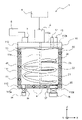
- FIG. 1 is a simplified configuration diagram showing a first embodiment of a washing/drying apparatus.
- FIG. 2 is a top view of the washing/drying apparatus.
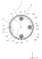
- FIG. 3 is an XY cross-sectional view of the cleaning/drying apparatus viewed from above.
- the vertical direction (height direction) when the cleaning/drying apparatus 1 is installed is the Z direction
- the horizontal directions are the X direction and the Y direction.
- the X, Y, and Z directions are orthogonal to each other, and when arranged in the order of X, Y, and Z, constitute a right-handed system.
- the forward direction of the Z direction is the upward direction
- the reverse direction of the Z direction is the downward direction.
- the cleaning/drying apparatus 1 is an apparatus capable of cleaning a powder-like object made of high-molecular-weight organic compounds with a cleaning liquid and drying the object.
- the washing and drying apparatus 1 includes a container 10, a stirring blade 20 arranged in the container 10, a filter 30 arranged in the container 10, a heater 40 arranged in the container 10, the stirring blade 20 and the heater 40 and a control device 5 for controlling the
- the container 10 has a container body 11 , and an object supply pipe 12 attached to the container body 11 , a cleaning liquid supply pipe 13 , an object discharge pipe 14 and a cleaning solution discharge pipe 15 .
- the object supply pipe 12 communicates with the inside of the container body 11 and can supply the object to be treated.
- the cleaning liquid supply pipe 13 communicates with the inside of the container body 11 and can supply the cleaning liquid.
- the object discharge pipe 14 communicates with the inside of the container body 11 and can discharge the object to be treated.
- the washing liquid discharge pipe 15 communicates with the inside of the container body 11 and can discharge the washing liquid.
- the stirring blade 20 is rotatable by being driven by the motor 6 attached to the container body 11 .
- the agitating blade 20 can agitate the object to be processed and the cleaning liquid during washing of the object to be processed, and can agitate the object to be processed during drying of the object to be processed.
- the filter 30 is provided on the container body 11 and positioned upstream of the cleaning liquid discharge pipe 15 .
- the filter 30 can filter the object to be processed and the cleaning liquid.
- the heater 40 can heat the inside of the container 10 .
- the heater 40 can heat the object to be processed when drying the object to be processed.
- the control device 5 rotates the stirring blades 20 during cleaning and drying of the object to be processed. Specifically, the control device 5 drives the motor 6 to rotate the stirring blades 20 . Further, the control device 5 operates the heater 40 when drying the object to be processed.
- the object to be processed can be supplied into the container body 11 from the object to be processed supply pipe 12 and the cleaning liquid can be supplied into the container body 11 from the cleaning solution supply pipe 13 .
- the object to be processed can be washed with the washing liquid while rotating the stirring blade 20 .
- the filter 30 can filter the object to be processed and the washing liquid.
- the object to be treated can be discharged from the object-to-be-treated discharge pipe 14 and the cleaning liquid can be discharged from the cleaning liquid discharge pipe 15 .
- the object to be processed can be dried by operating the heater 40 while rotating the stirring blade 20 .
- the inventors of the present application focused on the fact that a powdery material to be processed made of a high-molecular organic compound easily separates from water. It has been found that the cleaning can be carried out by stirring each of them. In other words, the inventors have found that it is not necessary to increase the number of rotations of the stirring blades for uniform dispersion, and cleaning can be performed even if the number of rotations of the stirring blades is reduced.
- the object to be treated when the object to be treated is made of fluororesin, the object to be treated has high water repellency, and the powdery object to be treated and the water are completely separated in a stationary state. It was found that the powdery materials to be processed can be stirred and washed by contacting the water and the powdery materials only at the solid-liquid interface.
- a powdery material to be processed made of a high-molecular organic compound can be washed even with a small rotation speed of the stirring blade during drying, and the washing step and the drying step of the present invention are performed. I came to invent a washing and drying device that can
- each member object to be processed, cleaning solution
- the object to be processed is made of resin, for example. According to this, the material to be treated is easily separated from water, and the material to be treated can be washed even if the rotational speed of the stirring blade 20 is reduced. Therefore, the load during cleaning of the stirring blades 20 can be reduced.
- the object to be treated is preferably made of fluororesin. According to this, the fluororesin has high water repellency, and the object to be treated is more easily separated from water, and the object to be treated can be washed even if the rotation speed of the stirring blade 20 is reduced. Therefore, the load during cleaning of the stirring blades 20 can be further reduced.
- the average particle size of the object to be processed is, for example, 20 ⁇ m or more.
- the average particle size means the particle size at an integrated value of 50% in the particle size distribution determined by the laser diffraction method.
- the cleaning liquid is, for example, water.
- the cleaning liquid may be an organic solvent such as ethyl alcohol or methyl alcohol.
- the object to be processed is dry
- the moisture content of the cleaning liquid contained in the object to be processed after drying is 0.2%, preferably 0.1% or less.
- the container body 11 has a cylindrical side wall portion 111, a top portion 112 attached to a first opening on the upper side of the side wall portion 111, and a bottom portion 113 attached to a second opening on the lower side of the side wall portion 111.
- the side wall portion 111 has, for example, a cylindrical shape.
- the top portion 112 and the bottom portion 113 are disk-shaped, for example.
- the central axis 11 a of the container body 11 coincides with the central axis of the cylindrical side wall portion 111 .
- the center of the top portion 112 intersects the central axis 11 a of the container body 11 .
- a center 113 d of the bottom portion 113 intersects the central axis 11 a of the container body 11 .
- the top portion 112 has an object-to-be-processed supply hole 112 a communicating with the object-to-be-processed supply pipe 12 and a cleaning solution supply hole 112 b communicating with the cleaning solution supply pipe 13 . There is one processing object supply hole 112a and one cleaning liquid supply hole 112b.
- the bottom portion 113 has an object-to-be-treated discharge hole 113 a communicating with the object-to-be-treated discharge pipe 14 and a cleaning solution discharge hole 113 b communicating with the cleaning solution discharge pipe 15 .
- a filter 30 is provided in each cleaning liquid discharge hole 113b. According to this, since the object to be processed discharge hole 113a and the cleaning liquid discharge hole 113b are provided in the bottom portion 113, the cleaning liquid and the to-be-processed material can be discharged efficiently by gravity.
- the object-to-be-processed supply pipe 12 and the cleaning liquid supply pipe 13 are attached to the top portion 112 .
- the number of the object to be processed supply pipe 12 and the cleaning liquid supply pipe 13 is one, respectively.
- the object-to-be-processed discharge pipe 14 and the cleaning liquid discharge pipe 15 are attached to the bottom portion 113 .
- a first sluice valve 16 is attached to the object discharge pipe 14
- a second sluice valve 17 is attached to the cleaning liquid discharge pipe 15 .
- the container 10 is preferably provided with a decompression device 8 capable of decompressing the inside of the container 10 .
- the decompression device 8 is connected to the container body 11 via the bag filter 7 attached to the top portion 112 .
- the bag filter 7 can prevent the material to be processed from being sucked into the pressure reducing device 8 when the pressure is reduced by the pressure reducing device 8 .
- the inside of the container 10 can be decompressed by the decompression device 8 at the time of drying, and the object to be processed can be dried at a low temperature.
- the container 10 can store cleaning liquid during cleaning. Specifically, during cleaning, the cleaning liquid can be stored in the container body 11 by closing the first and second gate valves 16 and 17 and supplying the cleaning liquid from the cleaning liquid supply pipe 13 into the container body 11 . can. According to the above configuration, the object to be processed can be washed by storing the cleaning liquid in the container 10, so the amount of the cleaning liquid can be reduced compared to the case of cleaning while spraying the cleaning liquid.
- the stirring blade 20 has a shaft 21 and fins 22 wound around the shaft 21 to form a continuous spiral along the shaft 21 .
- the shaft 21 is attached with a plurality of support portions 23 extending orthogonally to the axis of the shaft 21 , and the fins 22 are supported by the support portions 23 .
- the stirring blade 20 is attached to the container body 11 so that the axis of the shaft 21 coincides with the central axis 11 a of the container body 11 .
- the stirring blade 20 rotates about the central axis 11a. According to the above configuration, the fins 22 form a continuous spiral, so the degree of stirring by the stirring blades 20 can be increased.
- the stirring blade may be able to revolve while rotating.
- the stirring blade is attached to the container body 11 so that the axis of the shaft is eccentric with respect to the central axis 11a of the container body 11, and the stirring blade rotates about the axis of the shaft 21. It may be made to revolve around the central axis 11a. According to the above configuration, the stirring blades 20 can more reliably stir.
- the filter 30 is attached to the opening inside the container body 11 of the cleaning liquid discharge hole 113b.
- the filter 30 can filter out the cleaning liquid and the objects to be processed having a size of 50 ⁇ m or more.
- the cleaning liquid and the object to be processed can be separated by filtration.
- the filter 30 is made of, for example, metal such as stainless steel, or resin such as polyester or polyethylene. By adjusting the size of the mesh of the filter 30, it is possible to filter objects of various sizes.
- the heater 40 is provided on the side wall portion 111 and the bottom portion 112 of the container body 11 .
- the heater 40 has a plurality of pipes 41, and the plurality of pipes 41 are embedded in the side wall portion 111 and the bottom portion 112, respectively.
- the inside of the container body 11 can be heated by flowing a heat medium such as steam, oil, or hot water through the pipe 41 .
- a half-split pipe may be used instead of the pipe 41, and the cost can be reduced. Also, an electric heater may be used instead of the pipe 41, so that it can be arranged more densely.
- control device 5 operates the heater 40 while rotating the stirring blade 20 when cleaning the object to be processed, and rotating the stirring blade 20 when drying the object to be processed.
- control device 5 operates the heater 40 when cleaning the object to be processed. According to this, the cleaning effect can be improved by raising the temperature during cleaning.
- the control device 5 makes the rotation speed of the stirring blades 20 during washing the same as the rotation speed of the stirring blades 20 during drying.
- the rotation speed of the stirring blade 20 is 5-100 rpm, preferably 30-100 rpm.
- the control device 5 may set the number of revolutions of the stirring blades 20 during drying of the object to be processed to be lower than the number of revolutions of the stirring blades 20 during washing of the object to be processed.
- the rotation speed of the stirring blades 20 during drying is 30 rpm
- the rotation speed of the stirring blades 20 during washing is 50 to 100 rpm. According to this, during drying, only the object to be processed is stirred without containing the cleaning liquid, so the resistance of the object to be processed increases, but by reducing the rotation speed of the stirring blade 20, The load can be further reduced.
- the filter 30 is arranged in a region of the bottom portion 113 on the side of the outer circumference 113c.
- the region on the side of the outer periphery 113c of the bottom portion 113 is a region closer to the outer periphery 113c of the bottom portion 113 than half the distance from the center 113d of the bottom portion 113 to the inner surface 111a of the side wall portion 111 when viewed from the direction along the central axis 11a of the container body 11. refers to the area of An inner surface 111 a of the side wall portion 111 faces the internal space of the container body 11 .
- a virtual circle C indicates half the distance from the center 113d of the bottom portion 113 (the central axis 11a of the container body 11) to the inner surface 111a of the side wall portion 111. That is, the area of the bottom portion 113 on the side of the outer circumference 113c is the area on the side of the outer circumference 113c with respect to the virtual circle C. As shown in FIG. 3,
- the filter 30 When the filter 30 is arranged in the region on the outer circumference 113c side of the bottom portion 113, not only is the entire filter 30 arranged in the region on the outer circumference 113c side of the bottom portion 113, but more than half of the filter 30 is arranged on the bottom portion 113. is arranged in the area on the outer periphery 113c side of the . In this embodiment, all of the filters 30 are arranged in the region of the bottom portion 113 on the side of the outer circumference 113c.
- the centrifugal force of the stirring blades 20 rotates the stirring blades 20 so that the cleaning liquid can be blown to the area on the outer periphery 113c side of the bottom 113, and the filter 30 allows the cleaning liquid to flow to the area on the side of the outer periphery 113c. and washing liquid can be efficiently filtered.
- part of the heater 40 is arranged in the region of the bottom 113 on the center 113d side.
- a portion of the pipe 41 is arranged in a region on the center 113 d side of the bottom portion 113 .
- the area on the center 113 d side of the bottom portion 113 is the area on the center 113 d side of the bottom portion 113 that is half the distance from the center of the bottom portion 113 to the inner surface 111 a of the side wall portion 111 when viewed from the direction along the central axis 11 a of the container body 11 .
- part of the heater 40 is arranged in the region on the center 113d side of the bottom 113, so that the vicinity of the central axis 11a of the container body 11, which is difficult to heat, can be effectively heated during drying. It is possible to effectively dry the object to be treated.
- By adjusting the arrangement of the filter 30 and the heater 40 in the bottom portion 113 in this way it is possible to efficiently perform both the drainage of the cleaning liquid during cleaning and the drying of the object during drying.
- the inner surface 113e of the bottom portion 113 inside the container body 11 is flat, and the filter 30 is provided on the inner surface 113e side.
- An inner surface 113 e of the bottom portion 113 faces the internal space of the container body 11 .
- filter 30 is flush with inner surface 113e. According to the above configuration, since the inner surface 113e of the bottom portion 113 is flat, a large area of the filter 30 can be ensured while maintaining the filter 30 flat.
- the object discharge hole 113a and the cleaning liquid discharge hole 113b are arranged in the circumferential direction about the central axis 11a. .
- the opening of the object discharge hole 113a inside the container body 11 and the opening of the cleaning liquid discharge hole 113b inside the container body 11 are arranged along the circumferential direction.
- the filter 30 and the processed material discharge hole 113a are arranged along the circumferential direction.
- the object-to-be-processed discharge hole 113a and the cleaning liquid discharge hole 113b can be arranged so as to correspond to the rotation direction of the stirring blade 20, and the cleaning liquid can be efficiently drained from the cleaning liquid discharge hole 113b.
- the object to be treated can be efficiently recovered from the object discharge hole 113a.
- the cleaning liquid discharge holes 113b there are a plurality of cleaning liquid discharge holes 113b, and all of the object to be processed discharge holes 113a and cleaning liquid discharge holes 113b are arranged so that the center angles around the central axis 11a are at regular intervals.
- one processed object discharge hole 113a and three cleaning liquid discharge holes 113b are arranged so that the central angle is 90°. According to the above configuration, the cleaning liquid can be efficiently discharged from the plurality of cleaning liquid discharge holes 113b.
- FIG. 4 is an XY cross-sectional view of the washing/drying apparatus viewed from above.
- 11 inner openings are positioned between cleaning liquid discharge holes 113b, 113b adjacent in the circumferential direction.
- projections of openings of the object supply hole 112a and the cleaning liquid supply hole 112b are indicated by two-dot chain lines. These openings are located between circumferentially adjacent filters 30 , 30 .
- the object to be processed supplied into the container body 11 from the object to be processed supply pipe 12 and the cleaning liquid supplied into the container body 11 from the cleaning solution supply pipe 13 drop directly onto the filter 30 . and damage to the filter 30 can be reduced.
- the inner circumferential orbit 22a of the fins 22 of the stirring blade 20 due to the rotation of the stirring blade 20 is formed to discharge the material to be processed. It crosses the hole 113a and the cleaning liquid discharge hole 113b.
- the inner track 22a of the fins 22 intersects the filter 30 when viewed along the central axis 11a.
- the outer track 22 b of the fin 22 is close to the inner surface 111 a of the side wall portion 111 .
- the fins 22 of the stirring blades 20 pass directly above the processed material discharge holes 113a and the cleaning liquid discharge holes 113b.
- the cleaning liquid dropped from the inner peripheral side of the fins 22 can be effectively recovered from the cleaning liquid discharge holes 113b, and the workpiece dropped from the inner peripheral sides of the fins 22 can be effectively recovered from the treated article discharge holes 113a.
- the inner circumferential track 22a of the fins 22 intersects the area on the outer circumference 113c side of the bottom portion 113 from the center 30a of the filter 30 when viewed from the direction along the central axis 11a.
- the cleaning liquid dropped from the inner peripheral side of the fins 22 can be more effectively recovered from the cleaning liquid discharge holes 113b.
- the object to be processed is supplied into the container body 11 from the object to be processed supply pipe 12, and the cleaning liquid is supplied into the container body 11 from the cleaning solution supply pipe 13.
- the timing of supplying the object to be processed and the timing of supplying the cleaning liquid may be different or may be simultaneous.
- the object to be processed is washed with the cleaning liquid, and the cleaning liquid is discharged through the filter 30 to filter the object to be processed and the cleaning liquid.
- the first sluice valve 16 and the second sluice valve 17 are closed during washing, and the first sluice valve 16 is closed and the second sluice valve 17 is opened during drainage.
- the water may be drained after washing, or may be drained while washing. Also, washing and draining may be repeated multiple times.
- the heater 40 is operated to dry the object to be processed.
- the first gate valve 16 and the second gate valve 17 are closed.
- the work can be dried at a low temperature by operating the decompression device 8 .
- the second gate valve 17 may be opened to send air into the container body 11 while drying.
- the first sluice valve 16 is opened, the second sluice valve 17 is closed, and the material to be processed is collected from the material discharge pipe 14 .
- the cleaning and drying method there is no need to separately use a cleaning device and a drying device, and the cleaning process and the drying process can be performed with the same device, so the installation space for the device can be reduced. Moreover, since the cleaning process and the drying process can be performed in the same apparatus, there is no need to transfer the workpiece from the cleaning apparatus to the drying apparatus, thereby reducing the workload.
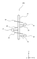
- FIG. 5 is a schematic configuration diagram of a stirring blade showing a second embodiment of the washing/drying apparatus.
- the agitating blade 20A includes a shaft 21 and a plurality of blades wound around the shaft 21 so as to form a discontinuous spiral along the shaft 21. of fins 22.
- the shaft 21 is attached with a plurality of support portions 23 extending orthogonally to the axis of the shaft 21 , and each fin 22 is supported by each support portion 23 .
- the spirally adjacent fins 22, 22 are spaced apart.
- a plate-like baffle plate may be installed on the inner surface 111a of the side wall portion 111 of the container body 11 toward the central axis 11a.
- the degree of stirring by the stirring blades 20A can be reduced.
- the object to be processed and the cleaning liquid can be dropped from the gaps between the fins 22, 22 adjacent in the spiral direction, and the object to be processed and the cleaning liquid can be efficiently collected.
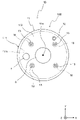
- FIG. 6 is a top view showing a third embodiment of the washing/drying apparatus.
- the third embodiment differs from the first embodiment in that a spray nozzle is provided. This different configuration is described below. The rest of the configuration is the same as that of the first embodiment, and the same reference numerals as those of the first embodiment are given, and the description thereof is omitted.
- the container 10B has a spray nozzle 18 that communicates with the cleaning liquid supply pipe 13 and can spray the cleaning liquid. Specifically, the spray nozzle 18 radially spreads the cleaning liquid.
- the spray nozzle 18 is attached to the inner surface of the top portion 112 inside the container body 11 .
- a plurality of cleaning liquid supply pipes 13 are provided, and spray nozzles 18 are communicated with each cleaning liquid supply pipe 13 . In this embodiment, there are four cleaning liquid supply pipes 13 and four spray nozzles 18, respectively.
- the object to be processed can be cleaned while the cleaning liquid is sprayed and discharged, so the container 10B can be made smaller than the case where the cleaning liquid is accumulated in the container 10B for cleaning.
- the spray nozzles 18 are arranged so that the central angles around the central axis 11a are equidistant. According to this, the cleaning liquid can be uniformly discharged to the entire area inside the container body 11 as viewed along the central axis 11a, the cleaning time can be shortened, and the amount of the cleaning liquid can be reduced.
- all the spray nozzles 18 are arranged at half the distance from the central axis 11 a to the inner surface 111 a of the side wall portion 111 .
- the cleaning liquid can be discharged more uniformly over the entire area inside the container body 11 as viewed along the central axis 11a, and the cleaning time can be further shortened, and the amount of cleaning liquid can be further reduced.
- the number of spray nozzles 18 may be one, but it is preferable to have a plurality of them. In particular, it is preferable that the number of spray nozzles 18 is four to six, so that the entire area inside the container body 11 can be uniformly sprayed.
- cleaning liquid discharge holes filters
- the numbers of the material supply holes, the cleaning liquid supply holes, and the material discharge holes may be increased.
- the numbers of the object supply pipes, the cleaning liquid supply pipes and the object discharge pipes may be increased.
- the fins of the stirring blades form a spiral, but they may not form a spiral, and the number of fins may be increased or decreased.
- the heaters are provided on the side walls and bottom, but they may be provided on the top, or may be provided on at least one of the top, side walls and bottom.
- Example 1 cleaning was performed using the cleaning/drying apparatus of the first embodiment. That is, washing was performed by storing the washing liquid in the container.
- ETFE ethylene-tetrafluoroethylene copolymer
- Example 1 a 100 L vacuum cleaning and drying apparatus was used, and a 100 mesh filter was used. Into the apparatus, 25 kg of unwashed polymerized powder was charged as an object to be treated, and 25 kg of pure water was charged as a cleaning liquid. After stirring for 30 minutes, the water was drained through the filter, and this was repeated 6 times, and the electrical conductivity in the final drain was measured. It was confirmed that the electric conductivity was 50 ⁇ S/cm or less, which is the target value.
- ETFE was used as the object to be treated in the comparative example.
- washing was performed using a 6000 L washing and drying apparatus having four flat plate stirring blades and baffle plates.
- 1200 kg of unwashed polymerized powder as a material to be treated is charged, 800 kg of pure water is charged as a cleaning liquid, and stirred for 60 minutes at a sufficient stirring rotation speed so that the powder is engulfed in water. carried out.
- dehydration was performed, and this was repeated six times.
- the polymer powder was sampled and mixed with pure water, and the electrolyte remaining in the powder was evaluated in terms of electrical conductivity, which was confirmed to be 50 ⁇ S/cm or less.
- Example 2 Specifically, in the same manner as in Example 1, after each washing, the polymer powder was sampled, the powder and pure water were mixed, and then the pure water was sampled to measure the electrical conductivity of the pure water. bottom. The powder was washed until it was confirmed that the electric conductivity was 50 ⁇ S/cm or less, which is the target value.
- Example 1 the electrical conductivity was reduced to the target value of 50 ⁇ S/cm or less by repeating the cleaning six times.
- Example 1 it was found that the cleaning performance was not lowered as compared with the comparative example.
- a container body 11 with an outer diameter of ⁇ 2800 mm was used, and a filter 30 with an outer diameter of ⁇ 404 mm was used.
- the area of the filter 30 was calculated from the outer diameter of the filter 30 .
- the occupation ratio of the filter 30 was calculated by calculating the ratio of the area of the filter 30 to the area of the inner surface 113e of the bottom portion 113 (hereinafter referred to as the total area). As a result, the occupation rate of one filter 30 was 2%.
- Region R includes the area of filter 30 plus the area occupied by reinforcing components for attaching filter 30 to bottom 113 .
- the area R is an area that partitions the filter 30 in the fan shape indicated by the chain double-dashed line centered on the central axis 11a and inscribed by the filter 30 .
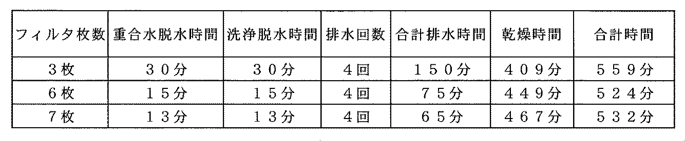
- Table 2 shows the relationship between the number of filters and the drainage time and drying time.
- the polymerization water dehydration time is the time to drain the water used when polymerizing the object to be treated after transferring it to the washing and drying machine.
- the washing/dehydration time is the time for washing and draining the object to be treated in one washing step.
- the number of times of water discharge is the number of times the object to be treated is washed and drained, and is the number of times of the washing process.
- the total drainage time is the time required for all the drainage, and is obtained by (polymerization water dehydration time + cleaning dehydration time x number of times of drainage).
- the drying time is the time to dry the object to be processed. In other words, the drying time is the time required for drying the object to be treated after the water is discharged.
- the total time is the time required for all drainage and drying, and is calculated by (total drainage time + drying time).
- the filter occupancy is 2% or more and 20% or less, preferably 4% or more and 16% or less, and more preferably 6% or more and 12% or less.
- the number of filters is 1 or more and 10 or less, preferably 2 or more and 8 or less, and more preferably 3 or more and 6. It is below.
- the drainage time and drying time can be well balanced, and the overall work time can be shortened. If the filter occupancy is less than the lower limit, the drainage time increases, and if the filter occupancy is greater than the upper limit, the drying time increases.
Landscapes
- Engineering & Computer Science (AREA)
- Mechanical Engineering (AREA)
- General Engineering & Computer Science (AREA)
- Life Sciences & Earth Sciences (AREA)
- Microbiology (AREA)
- Cleaning By Liquid Or Steam (AREA)
- Drying Of Solid Materials (AREA)
Abstract
Description
高分子の有機化合物からなる粉状の被処理物を洗浄液により洗浄し前記被処理物を乾燥可能である装置であり、
容器と、
前記容器内に配置された回転可能な撹拌翼と、
前記容器に配置され、前記被処理物と前記洗浄液を濾別可能であるフィルタと、
前記容器に配置され、前記容器内を加熱可能である加熱器と、
前記被処理物の洗浄時および乾燥時に前記攪拌翼を回転させ、前記被処理物の乾燥時に加熱器を作動させる制御装置と
を備え、
前記容器は、容器本体と、前記容器本体内に連通し前記被処理物を供給可能な被処理物供給管と、前記容器本体内に連通し前記洗浄液を供給可能な洗浄液供給管と、前記容器本体内に連通し前記被処理物を排出可能な被処理物排出管と、前記容器本体内に連通し前記洗浄液を排出可能な洗浄液排出管とを有し、
前記フィルタは、前記容器本体に設けられ、前記洗浄液排出管の上流側に位置している。
前記容器本体は、筒状の側壁部と、前記側壁部の第1開口部に取り付けられる天部と、前記側壁部の第2開口部に取り付けられる底部とを有し、
前記底部は、前記被処理物排出管に連通する被処理物排出孔と、前記洗浄液排出管に連通する洗浄液排出孔とを有し、
前記フィルタは、前記洗浄液排出孔に設けられている。
前記洗浄液排出孔は、複数存在し、
前記天部は、前記被処理物供給管に連通する被処理物供給孔と、前記洗浄液供給管に連通する洗浄液供給孔とを有し、
前記中心軸に沿った方向からみて、前記被処理物供給孔の前記容器本体内側の開口部と、前記洗浄液供給孔の前記容器本体内側の開口部とは、周方向に隣り合う前記洗浄液排出孔の間に位置する。
前記洗浄液排出孔は、複数存在し、
前記中心軸に沿った方向からみて、前記攪拌翼の回転による前記攪拌翼のフィンの内周軌道は、前記被処理物排出孔および前記洗浄液排出孔に交差する。
攪拌翼を回転させながら高分子の有機化合物からなる粉状の被処理物を洗浄液により洗浄し、フィルタを通して前記洗浄液を排出して前記被処理物と前記洗浄液を濾別する工程と、
前記攪拌翼を回転させつつ加熱器を作動させて前記被処理物を乾燥する工程と
を備える。
[概要構成]
図1は、洗浄乾燥装置の第1実施形態を示す簡略構成図である。図2は、洗浄乾燥装置の上面図である。図3は、洗浄乾燥装置の上方向からみたXY断面図である。
(被処理物、洗浄液)
被処理物は、例えば、樹脂からなる。これによれば、被処理物は、水と分離しやすくなり、撹拌翼20の回転数を小さくしても被処理物を洗浄できる。したがって、撹拌翼20の洗浄時の負荷を低減できる。
洗浄液は、例えば、水である。なお、洗浄液は、エチルアルコールやメチルアルコールなどの有機溶剤であってもよい。
容器本体11は、筒状の側壁部111と、側壁部111の上側の第1開口部に取り付けられる天部112と、側壁部111の下側の第2開口部に取り付けられる底部113とを有する。側壁部111は、例えば、円筒形状である。天部112および底部113は、例えば、円板形状である。
撹拌翼20は、シャフト21と、シャフト21に沿って連続した螺旋を形成するようにシャフト21の周囲に巻回されたフィン22とを有する。具体的に述べると、シャフト21には、シャフト21の軸心に直交して延在する複数の支持部23が取り付けられ、フィン22は、支持部23に支持される。攪拌翼20は、シャフト21の軸心が容器本体11の中心軸11aに一致するように、容器本体11に取り付けられる。攪拌翼20は、中心軸11aを中心として自転する。上記構成によれば、フィン22は、連続した螺旋を形成するので、撹拌翼20による攪拌の程度を大きくすることができる。
フィルタ30は、洗浄液排出孔113bの容器本体11内側の開口部に取り付けられている。好ましくは、フィルタ30は、洗浄液と50μm以上の被処理物を濾別可能である。上記構成によれば、洗浄液と被処理物を濾別できる。フィルタ30は、例えば、ステンレスなどの金属、または、ポリエステルやポリエチレンなどの樹脂から構成される。フィルタ30のメッシュのサイズを調整することで、種々の大きさの被処理物を濾別することができる。
加熱器40は、容器本体11の側壁部111および底部112に設けられている。具体的に述べると、加熱器40は、複数の配管41を有し、複数の配管41は、側壁部111および底部112のそれぞれに埋め込まれている。配管41に、スチーム、オイルまたは温水などの熱媒体を流すことで、容器本体11内を加熱することができる。
制御装置5は、被処理物の洗浄時に攪拌翼20を回転させ、被処理物の乾燥時に攪拌翼20を回転させながら加熱器40を作動させる。好ましくは、制御装置5は、被処理物の洗浄時に加熱器40を作動させる。これによれば、洗浄時に昇温することで洗浄効果を向上できる。
なお、制御装置5は、被処理物の乾燥時の撹拌翼20の回転数を被処理物の洗浄時の撹拌翼20の回転数よりも小さくしてもよい。例えば、乾燥時の撹拌翼20の回転数は、30rpmであり、洗浄時の撹拌翼20の回転数は、50~100rpmである。これによれば、乾燥時では、洗浄液を含まないで被処理物だけを攪拌するため、被処理物の抵抗が大きくなるが、撹拌翼20の回転数を小さくすることで、撹拌翼20にかかる負荷をより低減することができる。
図3に示すように、フィルタ30は、底部113の外周113c側の領域に配置されている。底部113の外周113c側の領域とは、容器本体11の中心軸11aに沿った方向からみて、底部113の中心113dから側壁部111の内面111aまでの距離の半分よりも底部113の外周113c側の領域をいう。側壁部111の内面111aは、容器本体11の内部空間に面している。
次に、高分子の有機化合物からなる粉状の被処理物を洗浄液により洗浄し、被処理物を乾燥する洗浄乾燥方法について説明する。
図5は、洗浄乾燥装置の第2実施形態を示す撹拌翼の概略構成図である。図5に示すように、第2実施形態の洗浄乾燥装置において、撹拌翼20Aは、シャフト21と、シャフト21に沿って不連続な螺旋を形成するようにシャフト21の周囲に巻回された複数のフィン22とを有する。具体的に述べると、シャフト21には、シャフト21の軸心に直交して延在する複数の支持部23が取り付けられ、各フィン22は、各支持部23に支持される。螺旋方向に隣り合うフィン22,22は、離隔している。
なお、混合性能を向上するために、容器本体11の側壁部111の内面111aに中心軸11aに向けて板状の邪魔板を設置してもよい。
図6は、洗浄乾燥装置の第3実施形態を示す上面図である。第3実施形態は、第1実施形態とは、噴霧ノズルを設けている点が相違する。この相違する構成を以下に説明する。その他の構成は、第1実施形態と同じ構成であり、第1実施形態と同一の符号を付してその説明を省略する。
次に、上記洗浄乾燥装置を用いて洗浄を行った第1実施例を示す。第1実施例の結果を表1に示す。

次に、フィルタのサイズの最適値についての実施例を示す。
5 制御装置
6 モータ
7 バグフィルタ
8 減圧装置
10,10B 容器
11 容器本体
11a 中心軸
111 側壁部
111a 内面
112 天部
112a 被処理物供給孔
112b 洗浄液供給孔
113 底部
113a 被処理物排出孔
113b 洗浄液排出孔
113c 外周
113d 中心
113e 内面
12 被処理物供給管
13 洗浄液供給管
14 被処理物排出管
15 洗浄液排出管
16,17 第1、第2仕切弁
18 噴霧ノズル
20,20A 攪拌翼
21 シャフト
22 フィン
22a 内周軌道
22b 外周軌道
30 フィルタ
30a 中心
40 加熱器
41 配管
C 仮想円
R 領域
Claims (20)
- 高分子の有機化合物からなる粉状の被処理物を洗浄液により洗浄し前記被処理物を乾燥可能である装置であり、
容器と、
前記容器内に配置された回転可能な撹拌翼と、
前記容器に配置され、前記被処理物と前記洗浄液を濾別可能であるフィルタと、
前記容器に配置され、前記容器内を加熱可能である加熱器と、
前記被処理物の洗浄時および乾燥時に前記攪拌翼を回転させ、前記被処理物の乾燥時に加熱器を作動させる制御装置と
を備え、
前記容器は、容器本体と、前記容器本体内に連通し前記被処理物を供給可能な被処理物供給管と、前記容器本体内に連通し前記洗浄液を供給可能な洗浄液供給管と、前記容器本体内に連通し前記被処理物を排出可能な被処理物排出管と、前記容器本体内に連通し前記洗浄液を排出可能な洗浄液排出管とを有し、
前記フィルタは、前記容器本体に設けられ、前記洗浄液排出管の上流側に位置している、洗浄乾燥装置。 - 前記フィルタは、前記洗浄液と50μm以上の前記被処理物を濾別可能である、請求項1に記載の洗浄乾燥装置。
- 前記攪拌翼は、シャフトと、前記シャフトに沿って連続した螺旋を形成するように前記シャフトの周囲に巻回されたフィンとを有する、請求項1または2に記載の洗浄乾燥装置。
- 前記攪拌翼は、シャフトと、前記シャフトに沿って不連続な螺旋を形成するように前記シャフトの周囲に巻回された複数のフィンとを有する、請求項1または2に記載の洗浄乾燥装置。
- 前記攪拌翼は、自転しつつ公転可能である、請求項1から4の何れか一つに記載の洗浄乾燥装置。
- さらに、前記容器内を減圧可能な減圧装置を備える、請求項1から5の何れか一つに記載の洗浄乾燥装置。
- 前記容器は、洗浄時に前記洗浄液を貯留可能である、請求項1から6の何れか一つに記載の洗浄乾燥装置。
- 前記容器は、前記洗浄液供給管に連通され前記洗浄液を噴霧可能な噴霧ノズルを有する、請求項1から6の何れか一つに記載の洗浄乾燥装置。
- 前記被処理物は、樹脂からなる、請求項1から8の何れか一つに記載の洗浄乾燥装置。
- 前記被処理物は、フッ素樹脂からなる、請求項1から8の何れか一つに記載の洗浄乾燥装置。
- 前記被処理物の平均粒径は、20μm以上である、請求項1から10の何れか一つに記載の洗浄乾燥装置。
- 前記容器本体は、筒状の側壁部と、前記側壁部の第1開口部に取り付けられる天部と、前記側壁部の第2開口部に取り付けられる底部とを有し、
前記底部は、前記被処理物排出管に連通する被処理物排出孔と、前記洗浄液排出管に連通する洗浄液排出孔とを有し、
前記フィルタは、前記洗浄液排出孔に設けられている、請求項1から11の何れか一つに記載の洗浄乾燥装置。 - 前記フィルタは、前記底部の外周側の領域に配置されている、請求項12に記載の洗浄乾燥装置。
- 前記加熱器の一部は、前記底部の中心側の領域に配置されている、請求項13に記載の洗浄乾燥装置。
- 前記底部の前記容器本体内側の内面は、平坦であり、前記フィルタは、前記内面側に設けられている、請求項12から14の何れか一つに記載の洗浄乾燥装置。
- 前記容器本体の中心軸に沿った方向からみて、前記被処理物排出孔と前記洗浄液排出孔とは、前記中心軸を中心とした周方向に、配置されている、請求項12から15の何れか一つに記載の洗浄乾燥装置。
- 前記洗浄液排出孔は、複数存在し、前記被処理物排出孔と前記洗浄液排出孔とは、前記中心軸を中心とした中心角度が等間隔となるように、配置されている、請求項16に記載の洗浄乾燥装置。
- 前記洗浄液排出孔は、複数存在し、
前記天部は、前記被処理物供給管に連通する被処理物供給孔と、前記洗浄液供給管に連通する洗浄液供給孔とを有し、
前記中心軸に沿った方向からみて、前記被処理物供給孔の前記容器本体内側の開口部と、前記洗浄液供給孔の前記容器本体内側の開口部とは、周方向に隣り合う前記洗浄液排出孔の間に位置する、請求項16または17に記載の洗浄乾燥装置。 - 前記洗浄液排出孔は、複数存在し、
前記中心軸に沿った方向からみて、前記攪拌翼の回転による前記攪拌翼のフィンの内周軌道は、前記被処理物排出孔および前記洗浄液排出孔に交差する、請求項16から18の何れか一つに記載の洗浄乾燥装置。 - 攪拌翼を回転させながら高分子の有機化合物からなる粉状の被処理物を洗浄液により洗浄し、フィルタを通して前記洗浄液を排出して前記被処理物と前記洗浄液を濾別する工程と、
前記攪拌翼を回転させつつ加熱器を作動させて前記被処理物を乾燥する工程と
を備える、洗浄乾燥方法。
Priority Applications (2)
| Application Number | Priority Date | Filing Date | Title |
|---|---|---|---|
| EP22837680.2A EP4350263A1 (en) | 2021-07-09 | 2022-07-05 | Washing/drying apparatus and washing/drying method |
| CN202280047940.9A CN117651836A (zh) | 2021-07-09 | 2022-07-05 | 清洗干燥装置和清洗干燥方法 |
Applications Claiming Priority (2)
| Application Number | Priority Date | Filing Date | Title |
|---|---|---|---|
| JP2021-114345 | 2021-07-09 | ||
| JP2021114345 | 2021-07-09 |
Publications (1)
| Publication Number | Publication Date |
|---|---|
| WO2023282266A1 true WO2023282266A1 (ja) | 2023-01-12 |
Family
ID=84800695
Family Applications (1)
| Application Number | Title | Priority Date | Filing Date |
|---|---|---|---|
| PCT/JP2022/026741 WO2023282266A1 (ja) | 2021-07-09 | 2022-07-05 | 洗浄乾燥装置および洗浄乾燥方法 |
Country Status (4)
| Country | Link |
|---|---|
| EP (1) | EP4350263A1 (ja) |
| JP (1) | JP7339575B2 (ja) |
| CN (1) | CN117651836A (ja) |
| WO (1) | WO2023282266A1 (ja) |
Cited By (2)
| Publication number | Priority date | Publication date | Assignee | Title |
|---|---|---|---|---|
| CN117906358A (zh) * | 2024-03-19 | 2024-04-19 | 泰州市永泰食品有限公司 | 一种黄精代用茶生产用的烘干设备 |
| CN117906358B (zh) * | 2024-03-19 | 2024-05-31 | 泰州市永泰食品有限公司 | 一种黄精代用茶生产用的烘干设备 |
Citations (9)
| Publication number | Priority date | Publication date | Assignee | Title |
|---|---|---|---|---|
| JPS5747230U (ja) * | 1980-08-29 | 1982-03-16 | ||
| JPS61107910A (ja) * | 1984-10-30 | 1986-05-26 | Chisso Corp | 濾過装置 |
| JPS61130893U (ja) | 1985-01-31 | 1986-08-15 | ||
| JPH0929011A (ja) * | 1995-07-17 | 1997-02-04 | Shinko Pantec Co Ltd | 濾過乾燥装置 |
| JP2001205067A (ja) * | 2000-01-27 | 2001-07-31 | Shinko Pantec Co Ltd | 攪拌翼およびこれを用いた濾過乾燥機 |
| JP2002156788A (ja) * | 2000-11-22 | 2002-05-31 | Mitsubishi Chemicals Corp | 静電荷像現像用トナーの分級方法 |
| JP2004148195A (ja) * | 2002-10-30 | 2004-05-27 | Kobelco Eco-Solutions Co Ltd | 濾過乾燥装置 |
| US20040136263A1 (en) * | 2002-12-28 | 2004-07-15 | Martin Backhaus | Helical-ribbon mixer |
| JP2013151621A (ja) * | 2012-01-26 | 2013-08-08 | Hitachi Chemical Co Ltd | 樹脂合成装置及び樹脂の合成方法 |
-
2022
- 2022-07-05 CN CN202280047940.9A patent/CN117651836A/zh active Pending
- 2022-07-05 EP EP22837680.2A patent/EP4350263A1/en active Pending
- 2022-07-05 WO PCT/JP2022/026741 patent/WO2023282266A1/ja active Application Filing
- 2022-07-05 JP JP2022108298A patent/JP7339575B2/ja active Active
Patent Citations (9)
| Publication number | Priority date | Publication date | Assignee | Title |
|---|---|---|---|---|
| JPS5747230U (ja) * | 1980-08-29 | 1982-03-16 | ||
| JPS61107910A (ja) * | 1984-10-30 | 1986-05-26 | Chisso Corp | 濾過装置 |
| JPS61130893U (ja) | 1985-01-31 | 1986-08-15 | ||
| JPH0929011A (ja) * | 1995-07-17 | 1997-02-04 | Shinko Pantec Co Ltd | 濾過乾燥装置 |
| JP2001205067A (ja) * | 2000-01-27 | 2001-07-31 | Shinko Pantec Co Ltd | 攪拌翼およびこれを用いた濾過乾燥機 |
| JP2002156788A (ja) * | 2000-11-22 | 2002-05-31 | Mitsubishi Chemicals Corp | 静電荷像現像用トナーの分級方法 |
| JP2004148195A (ja) * | 2002-10-30 | 2004-05-27 | Kobelco Eco-Solutions Co Ltd | 濾過乾燥装置 |
| US20040136263A1 (en) * | 2002-12-28 | 2004-07-15 | Martin Backhaus | Helical-ribbon mixer |
| JP2013151621A (ja) * | 2012-01-26 | 2013-08-08 | Hitachi Chemical Co Ltd | 樹脂合成装置及び樹脂の合成方法 |
Cited By (2)
| Publication number | Priority date | Publication date | Assignee | Title |
|---|---|---|---|---|
| CN117906358A (zh) * | 2024-03-19 | 2024-04-19 | 泰州市永泰食品有限公司 | 一种黄精代用茶生产用的烘干设备 |
| CN117906358B (zh) * | 2024-03-19 | 2024-05-31 | 泰州市永泰食品有限公司 | 一种黄精代用茶生产用的烘干设备 |
Also Published As
| Publication number | Publication date |
|---|---|
| JP7339575B2 (ja) | 2023-09-06 |
| CN117651836A (zh) | 2024-03-05 |
| EP4350263A1 (en) | 2024-04-10 |
| JP2023010643A (ja) | 2023-01-20 |
Similar Documents
| Publication | Publication Date | Title |
|---|---|---|
| JP5470252B2 (ja) | 塗料の製造方法および装置 | |
| US3898745A (en) | Drying apparatus for concentrating solutions | |
| JP5222183B2 (ja) | 連続式乾燥装置 | |
| WO2000074834A1 (fr) | Dispositif de granulation a rouleau centrifuge et procede de traitement de materiaux pulverulents et granulaires a l'aide de ce dispositif | |
| CN106387966A (zh) | 一种自洗型饲料搅拌混合与干燥一体化设备 | |
| CN207187946U (zh) | 一种高速搅拌研磨罐 | |
| CN206347827U (zh) | 一种化工原料高效搅拌干燥罐 | |
| CN116328697B (zh) | 一种光刻胶生产用原料反应釜及其控制方法 | |
| JP3143309B2 (ja) | 粉粒体処理装置 | |
| JP2003154249A (ja) | 混合乾燥機およびスラリー状被処理物の処理方法 | |
| WO2023282266A1 (ja) | 洗浄乾燥装置および洗浄乾燥方法 | |
| CN109260769A (zh) | 一种油漆除泡装置 | |
| CN209893814U (zh) | 一种高效振动流化床 | |
| JP2012233599A (ja) | 多管式乾燥装置 | |
| CN212253518U (zh) | 一种容量瓶用烘干装置 | |
| CN211754199U (zh) | 聚合硫酸铁粉末冷却装置 | |
| KR20210006368A (ko) | 배터리 페이스트 혼합기 및 배터리 페이스트를 만드는 방법 | |
| CN204404715U (zh) | 颗粒催化剂干燥装置 | |
| CN215893092U (zh) | 一种混凝土砂石烘干装置 | |
| JP2001205067A (ja) | 攪拌翼およびこれを用いた濾過乾燥機 | |
| JP3996256B2 (ja) | 粉粒体用振動処理装置 | |
| CN206284354U (zh) | 一种自洗型饲料搅拌混合与干燥一体化设备 | |
| JP2004085160A (ja) | 遠心式乾燥機 | |
| JP3890171B2 (ja) | 遠心転動造粒装置およびそれを用いた粉粒体処理方法 | |
| CN207769789U (zh) | 具有双混合装置的工业反应釜 |
Legal Events
| Date | Code | Title | Description |
|---|---|---|---|
| 121 | Ep: the epo has been informed by wipo that ep was designated in this application |
Ref document number: 22837680 Country of ref document: EP Kind code of ref document: A1 |
|
| WWE | Wipo information: entry into national phase |
Ref document number: 2022837680 Country of ref document: EP |
|
| WWE | Wipo information: entry into national phase |
Ref document number: 202280047940.9 Country of ref document: CN |
|
| ENP | Entry into the national phase |
Ref document number: 2022837680 Country of ref document: EP Effective date: 20240104 |
|
| NENP | Non-entry into the national phase |
Ref country code: DE |