WO2023276862A1 - 気密端子 - Google Patents
気密端子 Download PDFInfo
- Publication number
- WO2023276862A1 WO2023276862A1 PCT/JP2022/025224 JP2022025224W WO2023276862A1 WO 2023276862 A1 WO2023276862 A1 WO 2023276862A1 JP 2022025224 W JP2022025224 W JP 2022025224W WO 2023276862 A1 WO2023276862 A1 WO 2023276862A1
- Authority
- WO
- WIPO (PCT)
- Prior art keywords
- airtight terminal
- brazing
- terminal according
- main surface
- annular
- Prior art date
- Legal status (The legal status is an assumption and is not a legal conclusion. Google has not performed a legal analysis and makes no representation as to the accuracy of the status listed.)
- Ceased
Links
Images



Classifications
-
- H—ELECTRICITY
- H01—ELECTRIC ELEMENTS
- H01R—ELECTRICALLY-CONDUCTIVE CONNECTIONS; STRUCTURAL ASSOCIATIONS OF A PLURALITY OF MUTUALLY-INSULATED ELECTRICAL CONNECTING ELEMENTS; COUPLING DEVICES; CURRENT COLLECTORS
- H01R9/00—Structural associations of a plurality of mutually-insulated electrical connecting elements, e.g. terminal strips or terminal blocks; Terminals or binding posts mounted upon a base or in a case; Bases therefor
- H01R9/16—Fastening of connecting parts to base or case; Insulating connecting parts from base or case
Definitions
- the present disclosure relates to airtight terminals.
- the airtight terminals used in refrigerant compressors (compressors) for refrigerators and air conditioners are required to have high withstand voltage and withstand voltage because the compressor is placed inside a pressure-resistant container filled with refrigerant.
- a circular top plate portion a tubular portion extending downward from the outer peripheral end of the top plate portion, a flange portion extending from the lower end of the tubular portion, and an inner side from the top plate portion a metal outer ring provided with a small cylindrical portion extending along the length of the metal ring and having a lead sealing hole formed therein; a lead sealed in the lead sealing hole of the metal outer ring via a sealing glass; and an insulating sleeve welded to the sealing glass on the inner surface side of the ring so that the insulating sleeve extends beyond the small tubular portion in parallel with the top plate portion to the sealing glass on the inner surface side of the metal outer ring.
- a hermetic terminal for a compressor has been proposed which is welded to the . It also describes that the insulating sleeve is made of ceramics such as alumina and forsterite.
- the airtight terminal according to the present disclosure is a columnar insulating member comprising a conducting pin and through-holes that are open to a first main surface on the high voltage side and a second main surface on the low voltage side and into which the conducting pin is inserted.
- an annular member made of metal surrounding the insulating member, and a first brazing portion for fixing the conductive pin to the first main surface or the convex surface of the convex portion extending from the first main surface.
- the annular member includes an annular portion and a support portion that supports the insulating member on the low voltage side of the annular portion. The support surface of the support portion and the outer peripheral portion of the second main surface are joined via the second brazing portion.
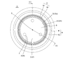
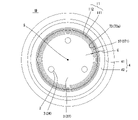
- FIG. 4 is a plan view of the hermetic terminal of a non-limiting embodiment of the present disclosure, viewed from the second major surface of the insulating member; 2 is a plan view of the airtight terminal shown in FIG. 1 as viewed from the first main surface of the insulating member; FIG. FIG. 3 is a cross-sectional view of the airtight terminal shown in FIGS. 1 and 2 taken along line III-III. 4 is an enlarged view of the periphery of the first to third brazed portions in the airtight terminal shown in FIG. 3; FIG. 5 is an enlarged view of the periphery of second and third brazing portions in the airtight terminal shown in FIG. 4; FIG. FIG.
- FIG. 6 is a view showing an airtight terminal of a non-limiting embodiment of the present disclosure, a cross-sectional view of the periphery of second and third brazing portions, corresponding to FIG. 5 ;
- FIG. 2 is a plan view of a non-limiting embodiment of the hermetic terminal of the present disclosure, corresponding to FIG. 1;
- FIG. 8 is a cross-sectional view of the periphery of second and third brazing portions in the airtight terminal shown in FIG. 7, and is a view corresponding to FIG. 5;
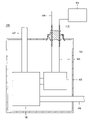
- 1 is a schematic diagram of a compressor according to a non-limiting embodiment of the present disclosure;
- the present disclosure provides an airtight terminal and a compressor that can maintain high pressure resistance.
- the airtight terminal according to the present disclosure can maintain high pressure resistance.
- Airtight terminals according to non-limiting embodiments of the present disclosure will be described in detail with reference to the drawings.
- the hermetic terminal may comprise any components not shown in the referenced figures.
- the dimensions of the members in each drawing do not faithfully represent the actual dimensions of the constituent members, the dimensional ratios of the respective members, and the like.
- the airtight terminal 1 comprises a conducting pin 2, an insulating member 3, an annular member 4 and a first brazing portion 5, as in the example shown in FIGS.
- This airtight terminal 1 can be used, for example, in a compressor or the like.
- each component of the airtight terminal 1 will be described in order, taking as an example the case where the airtight terminal 1 is for a compressor.
- the conductive pin 2 is conductive and can function as a conductive path for inputting and outputting electric signals to and from the pressure container to which the airtight terminal 1 is attached.
- Examples of the material of the conductive pin 2 include oxygen-free copper, tough pitch copper, copper such as phosphorus-deoxidized copper, titanium, nickel, austenitic stainless steel (eg, SUS304), and Cu—Ni alloy (eg, cupronickel). , Fe—Co alloys, Fe—Co—C alloys, Fe—Ni alloys, and Fe—Ni—Co alloys.
- the shape of the conducting pin 2 may be cylindrical or polygonal.
- the number of conductive pins 2 may be one or plural. When there are a plurality of conduction pins 2, the number of conduction pins 2 may be 2 or more and 50 or less.
- the insulating member 3 has insulating properties and can function as a member that electrically insulates and holds the conductive pin 2 .
- Examples of the material of the insulating member 3 include electrical insulating materials such as ceramics such as aluminum oxide sintered bodies.
- the shape of the insulating member 3 is cylindrical. More specifically, the insulating member 3 has a columnar shape extending along the axis S. As shown in FIG. The axis S passes through the respective centers of the first main surface 31 and the second main surface 32 of the insulating member 3, as in the example shown in FIG.
- the first main surface 31 is the main surface of the high pressure side A1.
- the second main surface 32 is the main surface of the low pressure side A2.
- the high pressure side A1 may mean the side with relatively high pressure
- the low pressure side A2 may mean the side with relatively low pressure.
- the first main surface 31 of the high pressure side A1 may be located at a higher pressure than the second main surface 32 of the low pressure side A2.
- the first main surface 31 of the high pressure side A1 may be located inside the pressure container
- the second main surface 32 of the low pressure side A2 may be located inside the pressure container. It may be located outside the pressure vessel.
- the insulating member 3 may have a convex portion 33 extending from the first main surface 31 .
- the number of convex portions 33 may be one, or plural.
- the number of convex portions 33 may be the same as the number of conductive pins 2 .
- the convex surface 331 (top surface) of the convex portion 33 may be provided with the metallized layer 6 .
- the thickness of the metallized layer 6 may be set to, for example, approximately 10 ⁇ m or more and 50 ⁇ m or less. Examples of the material of the metallized layer 6 include Mo--Mn alloy.
- the insulating member 3 has through holes 34 for inserting the conduction pins 2 .
- the through hole 34 opens to the first principal surface 31 and the second principal surface 32 .
- the through hole 34 may be opened to the convex surface 331 when the convex portion 33 is present.
- the through holes 34 may be opened in the surface of the metallized layer 6 .
- the through hole 34 may be opened at the end surface of the extension portion 37 on the low voltage side A2.
- the number of through-holes 34 may be one, or may be plural.
- the number of through holes 34 may be the same as the number of conductive pins 2 .
- the plurality of through-holes 34 may be positioned at regular intervals along the circumferential direction of the insulating member 3 .
- the three through-holes 34 may be positioned so as to have 120° rotational symmetry with respect to the axis S of the insulating member 3 .
- the conductive pin 2 is inserted into the through hole 34 with both ends projected.
- electricity is generated between the devices inside and outside the pressure vessel.
- the airtight terminal 1 can function as a terminal for transmitting signals.
- the annular member 4 can function as an attachment portion for attaching the airtight terminal 1 to the pressure-resistant container.
- An annular member 4 surrounds the insulating member 3 . More specifically, the annular member 4 surrounds at least part of the insulating member 3 .
- the annular member 4 is made of metal. Examples of metals include carbon steel for machine structural use, general structural rolled steel (cold rolled steel) such as SS400, and Fe--Ni--Co alloys.
- the first brazing portion 5 is a portion for fixing the conducting pin 2 to the first main surface 31 of the insulating member 3 or to the convex surface 331 of the convex portion 33 extending from the first main surface 31 .
- the first brazing portion 5 may fix the conductive pin 2 to the convex surface 331, as in the example shown in FIG.
- the first brazing portion 5 may fix the conductive pin 2 to the surface of the metallized layer 6 .
- the first brazing portion 5 is arranged on the first main surface 31 or the convex surface 331 via the flange 21 .
- the collar 21 may be positioned along the circumferential direction of the conduction pin 2 or may be annular along the circumferential direction of the conduction pin 2 .
- the first brazing part 5 may be one, or may be plural.
- the number of first brazing portions 5 may be the same as the number of conductive pins 2 . When there are a plurality of first brazing portions 5, the plurality of first brazing portions 5 are positioned apart from each other.
- brazing material of the first brazing portion 5 examples include silver brazing (eg, Bag-8, Bag-8a, Bag-9). This point is the same for the second brazing portion 7 and the third brazing portion 8 which will be described later.
- the annular member 4 includes an annular portion 41 and a support portion 42 that supports the insulating member 3 on the low voltage side A2 of the annular portion 41, as in the example shown in FIG. 4, the support surface 421 of the support portion 42 and the outer peripheral portion 321 of the second main surface 32 are joined via the second brazing portion 7. As shown in FIG. In these cases, even if a high pressure is applied from the high pressure side A1 toward the low pressure side A2, the support portion 42 supports the insulating member 3 on the low pressure side A2, so high pressure resistance can be maintained. .
- the support portion 42 may be integrally formed with the annular portion 41 .
- the inner diameter of the support portion 42 may be smaller than the inner diameter of the annular portion 41 .
- a support surface 421 of the support portion 42 may face the outer peripheral portion 321 of the second main surface 32 .
- At least a portion of the support surface 421 and at least a portion of the outer peripheral portion 321 may be joined via the second brazing portion 7 . If the insulating member 3 has the chamfered portion 35 chamfered from the outer edge of the second main surface 32 , the second brazed portion 7 may be positioned from the outer peripheral portion 321 to the chamfered portion 35 .
- the shape of the chamfered portion 35 may be planar or curved.
- the supporting surface 421 and the metallized layer 9 may be joined via the second brazing portion 7 .
- the outer peripheral portion 321 includes a plating layer 11 described later on the metallized layer 9, the supporting surface 421 and the plating layer 11 may be joined via the second brazing portion 7. (See Figure 8).
- the brazing material for the second brazing portion 7 may be the same as the brazing material for the first brazing portion 5, or may be different.
- the second brazing portion 7 may have a void 72 inside that does not communicate with the exposed surface 71 of the second brazing portion 7, as in the example shown in FIG. In this case, even if the temperature is repeatedly raised and lowered, the stress can be absorbed by the voids 72 , so cracks are less likely to occur in the second brazed portion 7 .
- the exposed surface 71 may be the surface of the second brazing portion 7 exposed between the support surface 421 and the outer peripheral portion 321 .
- the exposed surface 71 may be the surface of the fillet 73 .
- the number of voids 72 may be one or plural.
- a portion of the inner peripheral surface 411 of the annular portion 41 and a portion of the outer peripheral surface 36 of the insulating member 3 may be joined via the third brazing portion 8 .
- the radial movement of the insulating member 3 with respect to the annular member 4 is also restricted, it is possible to maintain even higher pressure resistance.
- part of the outer peripheral surface 36 when part of the outer peripheral surface 36 is provided with the metallized layer 9 , part of the inner peripheral surface 411 and the metallized layer 9 may be joined via the third brazing portion 8 . Further, when part of the outer peripheral surface 36 is provided with the plating layer 11 on the metallized layer 9, a part of the inner peripheral surface 411 and the plating layer 11 are joined via the third brazing portion 8. (See FIG. 8).
- the third brazed portion 8 may be positioned from a portion of the outer peripheral surface 36 to the chamfered portion 35 .
- the brazing material for the third brazing portion 8 may be the same as or different from the brazing material for the first brazing portion 5 or the second brazing portion 7 .
- the third brazing portion 8 may be separated from the second brazing portion 7 as in the example shown in FIG. In this case, even if the temperature is repeatedly raised and lowered, the stress can be absorbed by the gap V between the second brazed portion 7 and the third brazed portion 8 . Therefore, cracks are less likely to occur in the second brazed portion 7 and the third brazed portion 8 . At least part of the third brazed portion 8 may be separated from the second brazed portion 7 . For example, part of the third brazed portion 8 may be connected to the second brazed portion 7 .
- the third brazing portion 8 may have a void 82 inside that does not communicate with the exposed surface 81 of the third brazing portion 8 . In this case, even if the temperature is repeatedly raised and lowered, the stress can be absorbed by the gap 82 , so cracks are less likely to occur in the third brazed portion 8 .
- the exposed surface 81 may be the surface of the third brazing portion 8 exposed between a portion of the inner peripheral surface 411 and a portion of the outer peripheral surface 36 . If the third brazing portion 8 has a fillet 83 extending toward the high pressure side A1, the exposed surface 81 may be the surface of the fillet 83.
- the number of voids 82 may be one or plural.
- the radial width D1 of the support portion 42 may be 3% or more and 10% or less of the maximum value of the outer diameter D2 of the insulating member 3 .
- the width D1 is 3% or more of the maximum value of the outer diameter D2
- the area of the support surface 421 increases, so that even higher pressure resistance can be maintained.
- the width D1 is 10% or less of the maximum value of the outer diameter D2
- the creepage distance between the outer peripheral surface of the conducting pin 2 and the inner peripheral surface of the support portion 42 can be increased. A short circuit is less likely to occur between them.
- the width D1 is not limited to a specific value.
- the width D1 may be set to approximately 1 mm or more and 2.5 mm or less, for example.
- the maximum value of the outer diameter D2 is not limited to a specific value.
- the maximum value of the outer diameter D2 may be set to, for example, approximately 20 mm or more and 30 mm or less.
- the insulating member 3 may have, as in the example shown in FIG.
- the second brazing portion 7 may have a fillet 73 extending toward the extension portion 37 as in the example shown in FIG.
- a gap G space
- the tip portion 73 a of the fillet 73 may be separated from the outer peripheral surface 371 of the extension portion 37 .
- the presence of the fillet 73 improves the joint strength between the support portion 42 and the insulating member 3 . Further, when there is the extended portion 37 on the low-voltage side A2 of the insulating member 3, the gap G prevents the low-voltage side A2 of the insulating member 3 from being restrained. It is less likely to remain on the insulating member 3 and cracks are less likely to occur in the insulating member 3 .
- the gap G is not limited to a specific value.
- the gap G may be set to, for example, approximately 0.5 mm or more and 1.5 mm or less.
- the tip portion 73a of the fillet 73 may be positioned inside (on the axis S side) of the support portion 42 .
- the shape of the extending portion 37 may be cylindrical.
- the extending portion 37 may extend along the axis S.
- the maximum value of the length L of the insulating member 3 in the direction of the axis S may be set to, for example, about 14.5 mm or more and 24.5 mm or less.
- the outer peripheral portion 321 of the second principal surface 32 may be provided with an annular metallized layer 9 as in the examples shown in FIGS.
- the inner peripheral side of the surface of the metallized layer 9 may have a convex portion 91 along the circumferential direction.
- the end portion 9a on the inner peripheral side of the metallized layer 9 may be located inside the second brazing portion 7. Moreover, when there is a fillet 73 , the end portion 9 a may be located inside the fillet 73 . If there is an extension 37, the end 9a may be separated from the extension 37.
- the convex portion 91 may be positioned inside the second brazing portion 7 . Moreover, when there is a fillet 73 , the convex portion 91 may be positioned inside the fillet 73 . The convex portion 91 may be located in a region of the portion of the metallized layer 9 exposed from the fillet 73 that is closer to the end portion 9a than the center 9b of the width in the radial direction.
- the metallized layer 9 may be positioned from the outer peripheral portion 321 to the chamfered portion 35 . Also, the metallized layer 9 may be positioned from the outer peripheral portion 321 to a portion of the outer peripheral surface 36 .
- the convex portion 91 may be annular along the circumferential direction, as in the example shown in FIG. In this case, even if the amount of brazing material used to form the second brazing portion 7 is increased in order to improve the airtightness, the flow of the brazing material inward is reduced and the fillet 73 of the brazing material is reduced. It can be formed well. In addition, when the extension 37 is present, the fillet 73 is less likely to reach the extension 37, and even if the temperature is repeatedly increased and decreased, the stress is less likely to remain in the insulating member 3, and cracks are prevented from occurring in the insulation. It becomes difficult to occur in the member 3.
- the surface of the metallized layer 9 may have grooves 92 along the circumferential direction. In this case, stress is less likely to remain on the surface of the metallized layer 9 and cracks are less likely to occur in the metallized layer 9 even if the temperature is repeatedly raised and lowered.
- the number of grooves 92 may be one, or may be plural. When there are a plurality of grooves 92, the number of grooves 92 may be 2 or more and 5 or less. Also, the groove 92 may be located inside the second brazing portion 7 . If there is a fillet 73 , the groove 92 may be located inside the fillet 73 . The groove 92 may be located outside the protrusion 91 . Groove 92 may be annular along the circumference.
- the thickness of the metallized layer 9 may be set to, for example, approximately 10 ⁇ m or more and 50 ⁇ m or less.
- Examples of the material of the metallized layer 9 include Mo--Mn alloy.
- the material of the metallized layer 9 may be the same as or different from the material of the metallized layer 6 provided on the convex surface 331 of the convex portion 33 .
- the metallized layer 6 provided on the convex surface 331 may be called the first metallized layer 6
- the metallized layer 9 provided on the outer peripheral portion 321 may be called the second metallized layer 9 .
- the annular member 4 may have a collar portion 43 whose outer diameter increases toward the high pressure side A1, as in the example shown in FIG.
- the airtight terminal 1 may be attached to the pressure container via the collar portion 43 .
- airtight terminals 1A and 1B according to non-limiting embodiments of the present disclosure will be described with reference to the drawings.
- differences between the airtight terminals 1A and 1B and the airtight terminal 1 will be mainly described, and detailed descriptions of the points having the same configuration as the airtight terminal 1 may be omitted.
- the third brazing portion 8 may be connected to the second brazing portion 7 as in the example shown in FIG. In other words, the gap V between the second brazed portion 7 and the third brazed portion 8 may not exist. In this case, since the movement of the insulating member 3 with respect to the annular member 4 is further restricted, a higher pressure resistance can be maintained.
- the outer peripheral portion 321 of the second main surface 32 may include the ring-shaped metallized layer 9 and the plating layer 11 on the metallized layer 9. good.
- the inner peripheral side of the surface of the plating layer 11 may have a convex portion 111 along the circumferential direction.
- the inward flow of the brazing material is reduced and the fillet 73 of the brazing material is reduced. can be formed well.
- the fillet 73 is less likely to reach the extension 37, and even if the temperature is repeatedly increased and decreased, the stress is less likely to remain in the insulating member 3, and cracks are formed in the insulating member. It becomes difficult to occur in 3.
- the end portion 11a on the inner peripheral side of the plating layer 11 may be located inside the second brazing portion 7. Moreover, when there is a fillet 73 , the end portion 11 a may be located inside the fillet 73 . The end portion 11a may be separated from the extension portion 37 when the extension portion 37 is present.
- the convex portion 111 may be positioned inside the second brazing portion 7 . Moreover, when there is a fillet 73 , the convex portion 111 may be positioned inside the fillet 73 . The convex portion 111 may be located in a region of the portion of the plating layer 11 exposed from the fillet 73 that is closer to the end portion 11a than the center 11b of the width in the radial direction.
- the plating layer 11 may be positioned from the outer peripheral portion 321 to the chamfered portion 35 . Also, the plating layer 11 may be positioned from the outer peripheral portion 321 to a portion of the outer peripheral surface 36 .
- the thickness of the plating layer 11 may be set to, for example, approximately 2 ⁇ m or more and 6 ⁇ m or less.
- Examples of the material of the plating layer 11 include nickel.
- the convex portion 111 may be annular along the circumferential direction, as in the example shown in FIG. In this case, even if the amount of brazing material used to form the second brazing portion 7 is increased in order to improve the airtightness, the flow of the brazing material inward is reduced and the fillet 73 of the brazing material is reduced. It can be formed well. In addition, when the extension 37 is present, the fillet 73 is less likely to reach the extension 37, and even if the temperature is repeatedly increased and decreased, the stress is less likely to remain in the insulating member 3, and cracks are prevented from occurring in the insulation. It becomes difficult to occur in the member 3.
- the surface of the plating layer 11 may have grooves 112 along the circumferential direction. In this case, stress is less likely to remain on the surface of the metallized layer 9 and cracks are less likely to occur in the metallized layer 9 and the plating layer 11 even if the temperature is repeatedly raised and lowered.
- the number of grooves 112 may be one, or plural. When there are a plurality of grooves 112, the number of grooves 112 may be 2 or more and 5 or less. Also, the groove 112 may be located inside the second brazing portion 7 . If there is a fillet 73 , the groove 112 may be located inside the fillet 73 . The groove 112 may be positioned outside the protrusion 111 . Groove 112 may be annular along the circumference.
- the surface of the plating layer 11 may have an average cut level difference (R ⁇ c) of 5.1 ⁇ m or less in the roughness curve.
- R ⁇ c average cut level difference
- the average value of the cutting level difference (R ⁇ c) may be 1.2 ⁇ m or more.
- the average value of the cutting level difference (R ⁇ c) may be evaluated at the portion of the plating layer 11 exposed from the fillet 73 .
- the average value of the cutting level difference (R ⁇ c) may be larger on the outer peripheral side than on the inner peripheral side. Since the surface area where the fillet 73 has a high anchor effect to the plated layer 11 increases on the outer peripheral side, the bonding strength increases. Floating particles are less likely to adhere to the surface of the plating layer 11 on the inner peripheral side, and deterioration of the plating layer 11 is suppressed.
- the inner peripheral side when evaluating the average value of the cutting level difference (R ⁇ c) is the portion of the plating layer 11 exposed from the fillet 73 that is closer to the inner peripheral side of the plating layer 11 than the center 11b of the width in the radial direction.
- the outer peripheral side may be the side farther from the end 11a than the center 11b.
- the average cut level difference (R ⁇ c) represents the difference between the cut level at 25% load length rate on the roughness curve and the cut level at 75% load length rate on the roughness curve. good.
- the average value of the cutting level difference (R ⁇ c) may be, for example, a value obtained by measuring the surface roughness according to JIS B 0601:2001 and calculating the average value.
- the measurement conditions may be set as follows.
- Measuring machine Shape analysis laser microscope ("VK-X1100" manufactured by Keyence Corporation or its successor model) Measurement method: Surface roughness measurement Lighting: Coaxial epi-illumination Cutoff value ⁇ s: None Cutoff value ⁇ c: 0.08mm Cutoff value ⁇ f: None End effect correction: Yes Measurement magnification: 120 times (5 x 24) Measurement points: 3 points every 120° Measurement range: 2792 ⁇ m ⁇ 2093 ⁇ m/point Length per line to be measured: 2644 ⁇ m Main line of the line to be measured: 4 lines/point Direction of line to be measured: Circumferential direction
- the compressor 100 comprises a casing 101 (pressure-resistant container) and an airtight terminal 1.
- a casing 101 houses a motor 102 for compressing refrigerant.
- the airtight terminal 1 is attached to the casing 101 .
- Power from an external power supply 103 is supplied to the motor 102 via the conduction pins 2 .
- the compressor 100 comprises a casing 101 housing a motor 102 for compressing a refrigerant, and an airtight terminal 1 attached to the casing 101. Power is supplied from an external power source 103 through a conduction pin 2. supplied to the motor 102. In these cases, since the compressor 100 has the airtight terminal 1 capable of maintaining high pressure resistance, stable operation is possible over a long period of time.
- the airtight terminal 1 may be attached to the casing 101 by welding, for example.
- Motor 102 may be, for example, a three-phase motor.
- the external power supply 103 may be, for example, a three-phase AC power supply. Motor 102 and external power supply 103 may be electrically connected to conductive pins 2 via wiring 104 .
- the compressor 100 may comprise a compression mechanism 105, a suction pipe 106 and a discharge pipe 107.
- Compression mechanism 105 is housed in casing 101 .
- Suction tube 106 and discharge tube 107 are attached to casing 101 .
- Suction tube 106 and discharge tube 107 may be attached to casing 101 by welding, for example.
- the compression mechanism 105 is driven by the motor 102 and compresses the refrigerant.
- Suction tube 106 delivers refrigerant to compression mechanism 105 .
- the discharge pipe 107 discharges the refrigerant compressed by the compression mechanism 105 and sends it out to the refrigerant circulation system.
- the compressor 100 When the compressor 100 includes the compression mechanism 105, the suction pipe 106, and the discharge pipe 107, power is supplied from the external power supply 103 to the motor 102 through the airtight terminal 1, and the motor 102 is driven to operate the compression mechanism.
- 105 is enabled to compress the refrigerant. Refrigerant flows from the suction pipe 106 into the compression mechanism 105, and the compressed refrigerant flows out from the discharge pipe 107 and is sent to the refrigerant circulation system.
- compressor 100 is provided with the airtight terminal 1, but it is not limited to such a form.
- compressor 100 may comprise airtight terminal 1A or airtight terminal 1B.
- the airtight terminal 1 is used for compressors, but the airtight terminal 1 can also be used for other applications.
- Other applications may include, for example, sensor units, aluminum electrolytic capacitors, contact devices for relays, medical equipment, and the like.
Landscapes
- Connections Arranged To Contact A Plurality Of Conductors (AREA)
Priority Applications (1)
| Application Number | Priority Date | Filing Date | Title |
|---|---|---|---|
| JP2023531887A JP7566154B2 (ja) | 2021-06-28 | 2022-06-24 | 気密端子 |
Applications Claiming Priority (2)
| Application Number | Priority Date | Filing Date | Title |
|---|---|---|---|
| JP2021106729 | 2021-06-28 | ||
| JP2021-106729 | 2021-06-28 |
Publications (1)
| Publication Number | Publication Date |
|---|---|
| WO2023276862A1 true WO2023276862A1 (ja) | 2023-01-05 |
Family
ID=84691273
Family Applications (1)
| Application Number | Title | Priority Date | Filing Date |
|---|---|---|---|
| PCT/JP2022/025224 Ceased WO2023276862A1 (ja) | 2021-06-28 | 2022-06-24 | 気密端子 |
Country Status (2)
| Country | Link |
|---|---|
| JP (1) | JP7566154B2 (https=) |
| WO (1) | WO2023276862A1 (https=) |
Cited By (1)
| Publication number | Priority date | Publication date | Assignee | Title |
|---|---|---|---|---|
| WO2025205799A1 (ja) * | 2024-03-28 | 2025-10-02 | 京セラ株式会社 | 気密端子 |
Citations (7)
| Publication number | Priority date | Publication date | Assignee | Title |
|---|---|---|---|---|
| JPS59141179A (ja) * | 1983-01-31 | 1984-08-13 | 日本電気ホームエレクトロニクス株式会社 | 気密端子 |
| JPH05299132A (ja) * | 1992-04-21 | 1993-11-12 | Kyocera Corp | 気密端子 |
| JPH0668921A (ja) * | 1992-08-21 | 1994-03-11 | Kyocera Corp | 真空端子 |
| JP2013193935A (ja) * | 2012-03-21 | 2013-09-30 | Ngk Insulators Ltd | セラミックス部材と金属部材との接合体及びその製法 |
| JP2017022334A (ja) * | 2015-07-15 | 2017-01-26 | Ngkエレクトロデバイス株式会社 | 多数個取り配線基板及びその製造方法 |
| CN206098773U (zh) * | 2016-09-07 | 2017-04-12 | 深圳市南方源芯电气有限公司 | 汽车空调压缩机接线柱的封装装置 |
| JP2019149304A (ja) * | 2018-02-27 | 2019-09-05 | 京セラ株式会社 | 密封端子 |
-
2022
- 2022-06-24 JP JP2023531887A patent/JP7566154B2/ja active Active
- 2022-06-24 WO PCT/JP2022/025224 patent/WO2023276862A1/ja not_active Ceased
Patent Citations (7)
| Publication number | Priority date | Publication date | Assignee | Title |
|---|---|---|---|---|
| JPS59141179A (ja) * | 1983-01-31 | 1984-08-13 | 日本電気ホームエレクトロニクス株式会社 | 気密端子 |
| JPH05299132A (ja) * | 1992-04-21 | 1993-11-12 | Kyocera Corp | 気密端子 |
| JPH0668921A (ja) * | 1992-08-21 | 1994-03-11 | Kyocera Corp | 真空端子 |
| JP2013193935A (ja) * | 2012-03-21 | 2013-09-30 | Ngk Insulators Ltd | セラミックス部材と金属部材との接合体及びその製法 |
| JP2017022334A (ja) * | 2015-07-15 | 2017-01-26 | Ngkエレクトロデバイス株式会社 | 多数個取り配線基板及びその製造方法 |
| CN206098773U (zh) * | 2016-09-07 | 2017-04-12 | 深圳市南方源芯电气有限公司 | 汽车空调压缩机接线柱的封装装置 |
| JP2019149304A (ja) * | 2018-02-27 | 2019-09-05 | 京セラ株式会社 | 密封端子 |
Cited By (1)
| Publication number | Priority date | Publication date | Assignee | Title |
|---|---|---|---|---|
| WO2025205799A1 (ja) * | 2024-03-28 | 2025-10-02 | 京セラ株式会社 | 気密端子 |
Also Published As
| Publication number | Publication date |
|---|---|
| JP7566154B2 (ja) | 2024-10-11 |
| JPWO2023276862A1 (https=) | 2023-01-05 |
Similar Documents
| Publication | Publication Date | Title |
|---|---|---|
| JP6185064B2 (ja) | 完全に絶縁された直接ワイヤ接続を備える気密端子 | |
| EP2297821A2 (en) | Electric power terminal feed-through | |
| JP7566154B2 (ja) | 気密端子 | |
| CN117996506B (zh) | 不锈钢外壳的高温防腐密封连接器及其加工方法 | |
| CN106169453A (zh) | 半导体装置、金属部件以及半导体装置的制造方法 | |
| JP2019149304A (ja) | 密封端子 | |
| WO2023063108A1 (ja) | 気密端子および圧縮機 | |
| CN212366308U (zh) | 一种两针大尺寸陶瓷封装连接器 | |
| CN102570094A (zh) | 一种超高真空装置用高压引线组件及制造方法 | |
| JP2023001603A (ja) | 保持装置 | |
| JP5646804B2 (ja) | 可撓性高温ケーブル | |
| JP2015064928A (ja) | 気密端子 | |
| JP7701985B2 (ja) | 気密端子および圧縮機 | |
| JP6680391B2 (ja) | 半導体装置、金属部材および半導体装置の製造方法 | |
| JP2024025435A (ja) | 保持装置 | |
| JP7739191B2 (ja) | 気密端子 | |
| CN111785570A (zh) | 一种具有大电流、低引线电阻封接电磁继电器外壳 | |
| CN218958685U (zh) | 一种浸油式高功率电机的密封导电结构 | |
| CN214481845U (zh) | 高可靠性管脚引线焊片熔封工艺结构 | |
| JP3752424B2 (ja) | 絶縁継手 | |
| JP6674815B2 (ja) | 二重封止型ターミナルヘッダの製造方法 | |
| EP3852199A1 (en) | Hermetic terminal | |
| JP6167681B2 (ja) | サージアブソーバ | |
| JP2024171820A (ja) | 半導体装置 | |
| JPH07211587A (ja) | 真空コンデンサ |
Legal Events
| Date | Code | Title | Description |
|---|---|---|---|
| 121 | Ep: the epo has been informed by wipo that ep was designated in this application |
Ref document number: 22833009 Country of ref document: EP Kind code of ref document: A1 |
|
| WWE | Wipo information: entry into national phase |
Ref document number: 2023531887 Country of ref document: JP |
|
| NENP | Non-entry into the national phase |
Ref country code: DE |
|
| 122 | Ep: pct application non-entry in european phase |
Ref document number: 22833009 Country of ref document: EP Kind code of ref document: A1 |