WO2023248357A1 - 付加製造装置および付加製造方法 - Google Patents
付加製造装置および付加製造方法 Download PDFInfo
- Publication number
- WO2023248357A1 WO2023248357A1 PCT/JP2022/024755 JP2022024755W WO2023248357A1 WO 2023248357 A1 WO2023248357 A1 WO 2023248357A1 JP 2022024755 W JP2022024755 W JP 2022024755W WO 2023248357 A1 WO2023248357 A1 WO 2023248357A1
- Authority
- WO
- WIPO (PCT)
- Prior art keywords
- workpiece
- additive manufacturing
- manufacturing apparatus
- laser beam
- wire
- Prior art date
- Legal status (The legal status is an assumption and is not a legal conclusion. Google has not performed a legal analysis and makes no representation as to the accuracy of the status listed.)
- Ceased
Links
Images












Classifications
-
- B—PERFORMING OPERATIONS; TRANSPORTING
- B22—CASTING; POWDER METALLURGY
- B22F—WORKING METALLIC POWDER; MANUFACTURE OF ARTICLES FROM METALLIC POWDER; MAKING METALLIC POWDER; APPARATUS OR DEVICES SPECIALLY ADAPTED FOR METALLIC POWDER
- B22F10/00—Additive manufacturing of workpieces or articles from metallic powder
- B22F10/20—Direct sintering or melting
- B22F10/22—Direct deposition of molten metal
-
- B—PERFORMING OPERATIONS; TRANSPORTING
- B23—MACHINE TOOLS; METAL-WORKING NOT OTHERWISE PROVIDED FOR
- B23K—SOLDERING OR UNSOLDERING; WELDING; CLADDING OR PLATING BY SOLDERING OR WELDING; CUTTING BY APPLYING HEAT LOCALLY, e.g. FLAME CUTTING; WORKING BY LASER BEAM
- B23K26/00—Working by laser beam, e.g. welding, cutting or boring
- B23K26/34—Laser welding for purposes other than joining
- B23K26/342—Build-up welding
-
- B—PERFORMING OPERATIONS; TRANSPORTING
- B22—CASTING; POWDER METALLURGY
- B22F—WORKING METALLIC POWDER; MANUFACTURE OF ARTICLES FROM METALLIC POWDER; MAKING METALLIC POWDER; APPARATUS OR DEVICES SPECIALLY ADAPTED FOR METALLIC POWDER
- B22F10/00—Additive manufacturing of workpieces or articles from metallic powder
- B22F10/30—Process control
- B22F10/36—Process control of energy beam parameters
-
- B—PERFORMING OPERATIONS; TRANSPORTING
- B22—CASTING; POWDER METALLURGY
- B22F—WORKING METALLIC POWDER; MANUFACTURE OF ARTICLES FROM METALLIC POWDER; MAKING METALLIC POWDER; APPARATUS OR DEVICES SPECIALLY ADAPTED FOR METALLIC POWDER
- B22F12/00—Apparatus or devices specially adapted for additive manufacturing; Auxiliary means for additive manufacturing; Combinations of additive manufacturing apparatus or devices with other processing apparatus or devices
- B22F12/22—Driving means
- B22F12/224—Driving means for motion along a direction within the plane of a layer
-
- B—PERFORMING OPERATIONS; TRANSPORTING
- B23—MACHINE TOOLS; METAL-WORKING NOT OTHERWISE PROVIDED FOR
- B23K—SOLDERING OR UNSOLDERING; WELDING; CLADDING OR PLATING BY SOLDERING OR WELDING; CUTTING BY APPLYING HEAT LOCALLY, e.g. FLAME CUTTING; WORKING BY LASER BEAM
- B23K26/00—Working by laser beam, e.g. welding, cutting or boring
- B23K26/08—Devices involving relative movement between laser beam and workpiece
- B23K26/082—Scanning systems, i.e. devices involving movement of the laser beam relative to the laser head
-
- B—PERFORMING OPERATIONS; TRANSPORTING
- B23—MACHINE TOOLS; METAL-WORKING NOT OTHERWISE PROVIDED FOR
- B23K—SOLDERING OR UNSOLDERING; WELDING; CLADDING OR PLATING BY SOLDERING OR WELDING; CUTTING BY APPLYING HEAT LOCALLY, e.g. FLAME CUTTING; WORKING BY LASER BEAM
- B23K26/00—Working by laser beam, e.g. welding, cutting or boring
- B23K26/08—Devices involving relative movement between laser beam and workpiece
- B23K26/0823—Devices involving rotation of the workpiece
-
- B—PERFORMING OPERATIONS; TRANSPORTING
- B23—MACHINE TOOLS; METAL-WORKING NOT OTHERWISE PROVIDED FOR
- B23K—SOLDERING OR UNSOLDERING; WELDING; CLADDING OR PLATING BY SOLDERING OR WELDING; CUTTING BY APPLYING HEAT LOCALLY, e.g. FLAME CUTTING; WORKING BY LASER BEAM
- B23K26/00—Working by laser beam, e.g. welding, cutting or boring
- B23K26/14—Working by laser beam, e.g. welding, cutting or boring using a fluid stream, e.g. a jet of gas, in conjunction with the laser beam; Nozzles therefor
-
- B—PERFORMING OPERATIONS; TRANSPORTING
- B23—MACHINE TOOLS; METAL-WORKING NOT OTHERWISE PROVIDED FOR
- B23K—SOLDERING OR UNSOLDERING; WELDING; CLADDING OR PLATING BY SOLDERING OR WELDING; CUTTING BY APPLYING HEAT LOCALLY, e.g. FLAME CUTTING; WORKING BY LASER BEAM
- B23K26/00—Working by laser beam, e.g. welding, cutting or boring
- B23K26/14—Working by laser beam, e.g. welding, cutting or boring using a fluid stream, e.g. a jet of gas, in conjunction with the laser beam; Nozzles therefor
- B23K26/1462—Nozzles; Features related to nozzles
- B23K26/1464—Supply to, or discharge from, nozzles of media, e.g. gas, powder, wire
- B23K26/147—Features outside the nozzle for feeding the fluid stream towards the workpiece
-
- B—PERFORMING OPERATIONS; TRANSPORTING
- B23—MACHINE TOOLS; METAL-WORKING NOT OTHERWISE PROVIDED FOR
- B23K—SOLDERING OR UNSOLDERING; WELDING; CLADDING OR PLATING BY SOLDERING OR WELDING; CUTTING BY APPLYING HEAT LOCALLY, e.g. FLAME CUTTING; WORKING BY LASER BEAM
- B23K26/00—Working by laser beam, e.g. welding, cutting or boring
- B23K26/14—Working by laser beam, e.g. welding, cutting or boring using a fluid stream, e.g. a jet of gas, in conjunction with the laser beam; Nozzles therefor
- B23K26/1462—Nozzles; Features related to nozzles
- B23K26/1464—Supply to, or discharge from, nozzles of media, e.g. gas, powder, wire
- B23K26/1476—Features inside the nozzle for feeding the fluid stream through the nozzle
-
- B—PERFORMING OPERATIONS; TRANSPORTING
- B23—MACHINE TOOLS; METAL-WORKING NOT OTHERWISE PROVIDED FOR
- B23K—SOLDERING OR UNSOLDERING; WELDING; CLADDING OR PLATING BY SOLDERING OR WELDING; CUTTING BY APPLYING HEAT LOCALLY, e.g. FLAME CUTTING; WORKING BY LASER BEAM
- B23K26/00—Working by laser beam, e.g. welding, cutting or boring
- B23K26/70—Auxiliary operations or equipment
- B23K26/702—Auxiliary equipment
-
- B—PERFORMING OPERATIONS; TRANSPORTING
- B33—ADDITIVE MANUFACTURING TECHNOLOGY
- B33Y—ADDITIVE MANUFACTURING, i.e. MANUFACTURING OF THREE-DIMENSIONAL [3D] OBJECTS BY ADDITIVE DEPOSITION, ADDITIVE AGGLOMERATION OR ADDITIVE LAYERING, e.g. BY 3D PRINTING, STEREOLITHOGRAPHY OR SELECTIVE LASER SINTERING
- B33Y10/00—Processes of additive manufacturing
-
- B—PERFORMING OPERATIONS; TRANSPORTING
- B33—ADDITIVE MANUFACTURING TECHNOLOGY
- B33Y—ADDITIVE MANUFACTURING, i.e. MANUFACTURING OF THREE-DIMENSIONAL [3D] OBJECTS BY ADDITIVE DEPOSITION, ADDITIVE AGGLOMERATION OR ADDITIVE LAYERING, e.g. BY 3D PRINTING, STEREOLITHOGRAPHY OR SELECTIVE LASER SINTERING
- B33Y30/00—Apparatus for additive manufacturing; Details thereof or accessories therefor
-
- B—PERFORMING OPERATIONS; TRANSPORTING
- B33—ADDITIVE MANUFACTURING TECHNOLOGY
- B33Y—ADDITIVE MANUFACTURING, i.e. MANUFACTURING OF THREE-DIMENSIONAL [3D] OBJECTS BY ADDITIVE DEPOSITION, ADDITIVE AGGLOMERATION OR ADDITIVE LAYERING, e.g. BY 3D PRINTING, STEREOLITHOGRAPHY OR SELECTIVE LASER SINTERING
- B33Y50/00—Data acquisition or data processing for additive manufacturing
- B33Y50/02—Data acquisition or data processing for additive manufacturing for controlling or regulating additive manufacturing processes
-
- Y—GENERAL TAGGING OF NEW TECHNOLOGICAL DEVELOPMENTS; GENERAL TAGGING OF CROSS-SECTIONAL TECHNOLOGIES SPANNING OVER SEVERAL SECTIONS OF THE IPC; TECHNICAL SUBJECTS COVERED BY FORMER USPC CROSS-REFERENCE ART COLLECTIONS [XRACs] AND DIGESTS
- Y02—TECHNOLOGIES OR APPLICATIONS FOR MITIGATION OR ADAPTATION AGAINST CLIMATE CHANGE
- Y02P—CLIMATE CHANGE MITIGATION TECHNOLOGIES IN THE PRODUCTION OR PROCESSING OF GOODS
- Y02P10/00—Technologies related to metal processing
- Y02P10/25—Process efficiency
Definitions
- the present disclosure relates to an additive manufacturing device and an additive manufacturing method for manufacturing a three-dimensionally shaped object.
- additive manufacturing (AM) technology is known as one of the technologies for manufacturing three-dimensional objects.
- DED Directed Energy Deposition
- additive manufacturing equipment moves materials and workpieces while feeding them to commanded locations. Beads are formed by irradiating the beam with a beam.
- a bead is a solidified material obtained by solidifying a molten material on a workpiece.
- Additive manufacturing equipment manufactures shaped objects by sequentially stacking beads.
- Patent Document 1 discloses a DED type additive manufacturing apparatus that manufactures a shaped object by supplying a wire, which is a metal material, to a workpiece.
- the present disclosure has been made in view of the above, and aims to provide an additive manufacturing device that can realize stable processing.
- an additive manufacturing apparatus that manufactures a shaped object by adding a material melted by beam irradiation to a workpiece.
- the additive manufacturing apparatus includes a processing head, a beam nozzle through which a beam emitted from the processing head passes, a material supply section that supplies material to a workpiece, and a tip portion of the material on the side of the workpiece.
- a first drive unit that moves the beam relative to the workpiece a second drive unit that moves the beam in a direction included in a reference plane that is a plane perpendicular to the central axis of the beam nozzle, and a second drive unit that moves the beam relative to the workpiece.
- the direction in which the beam is moved is determined based on the traveling direction, which is a direction included in the reference plane and is the direction in which the tip moves relative to the workpiece, and is different from the movement of the tip relative to the workpiece. and a control device that controls the first drive section and the second drive section so that the beam can be moved.
- the additive manufacturing apparatus according to the present disclosure has the effect of realizing stable processing.
- Flowchart showing an example of the operation procedure of the additive manufacturing apparatus according to the first embodiment A diagram illustrating how a modeled object is formed by the additive manufacturing apparatus according to Embodiment 1.
- a diagram for explaining movement of a laser beam in the additive manufacturing apparatus according to Embodiment 1. A diagram showing how a laser beam is moved by the additive manufacturing apparatus according to Embodiment 1.
- a diagram showing how a laser beam is moved by the beam driving unit of the additive manufacturing apparatus according to the second embodiment.
- a second diagram for explaining the irradiation area in which the laser beam is moved by the beam driving unit of the additive manufacturing apparatus according to the second embodiment A diagram showing a first modified example of the irradiation area in which the laser beam is moved by the beam driving unit of the additive manufacturing apparatus according to the second embodiment.
- a diagram showing how a modeled object is formed by the additive manufacturing apparatus according to the third embodiment A diagram for explaining the shape of a bead formed by the additive manufacturing apparatus according to Embodiment 3.
- a diagram showing how a laser beam is moved by the additive manufacturing apparatus according to Embodiment 4 A diagram showing beads formed in Embodiment 4 A diagram showing beads formed in a comparative example of Embodiment 4 A diagram showing how a modeled object is formed by the additive manufacturing apparatus according to the fifth embodiment
- a diagram for explaining the tenth step of forming a bead by the additive manufacturing apparatus according to the fifth embodiment A diagram showing a configuration example of a control circuit according to Embodiments 1 to 5.
- FIG. 1 is a diagram showing a configuration example of an additive manufacturing apparatus 100 according to a first embodiment.
- the additive manufacturing apparatus 100 is a machine tool that manufactures a shaped object by adding a material melted by beam irradiation to a workpiece.
- the beam is a laser beam 24, and the material is a metal wire 5.
- the additive manufacturing device 100 is a DED type additive manufacturing device.
- the additive manufacturing apparatus 100 forms a bead by irradiating the wire 5 and the workpiece with a laser beam 24 while supplying the wire 5 to a commanded position.
- a bead layer is formed on the base material 17 by arranging a plurality of beads.
- a bead deposit 18 is formed by stacking the layers of beads. In this way, the additive manufacturing apparatus 100 manufactures a three-dimensional object by stacking beads.
- the base material 17 shown in FIG. 1 is a plate material.
- the base material 17 may be other than a plate material.
- the workpiece is the object to which the molten material is applied, such as a substrate 17 or a deposit 18.
- the X axis, Y axis, and Z axis are three axes that are perpendicular to each other.
- the X axis and the Y axis are two horizontal axes.
- the Z-axis direction is the vertical direction.
- the direction of the arrow in the X-axis direction is the plus X direction, and the direction opposite to the plus X direction is the minus X direction.
- the direction of the arrow is defined as the plus Y direction
- the direction opposite to the plus Y direction is defined as the minus Y direction.
- the direction of the arrow is defined as the plus Z direction
- the direction opposite to the plus Z direction is defined as the minus Z direction.
- the laser oscillator 2 which is a beam source, outputs a laser beam 24.
- a laser beam 24 outputted by the laser oscillator 2 propagates to the beam driving section 20 through the fiber cable 3 which is an optical transmission path.
- the beam drive section 20 is attached to the processing head 10. Details of the beam driving section 20 will be described later.
- the laser beam 24 passes through the beam driver 20 and enters the processing head 10 .
- An optical system such as a collimating optical system or a condensing optical system is arranged inside the processing head 10. Illustration of the optical system is omitted.
- the laser oscillator 2, fiber cable 3, and processing head 10 constitute an irradiation unit that irradiates the workpiece with the laser beam 24.
- the processing head 10 is provided with a beam nozzle 11 through which the laser beam 24 emitted from the processing head 10 passes, and a gas nozzle 13 through which shielding gas is injected.
- the central axis of the beam nozzle 11 coincides with the optical axis of the optical system.
- the laser beam 24 passes through an optical system inside the processing head 10, passes through the beam nozzle 11, and is emitted from the processing head 10.
- the laser beam 24 propagates from the beam nozzle 11 towards the workpiece.
- Laser beam 24 is a heat source that melts wire 5.
- the gas nozzle 13 injects an inert gas 25, which is a shielding gas, toward a processing area 34 where processing is performed. By injecting the inert gas 25, oxidation of the bead is reduced and the formed bead is cooled.
- Gas supply device 7 supplies inert gas 25. Inert gas 25 is supplied from gas supply device 7 to gas nozzle 13 through piping 8 .
- the direction of the central axis of the beam nozzle 11 is the Z-axis direction.
- the central axis of the gas nozzle 13 coincides with the central axis of the beam nozzle 11. That is, the gas nozzle 13 is provided coaxially with the beam nozzle 11.
- Gas nozzle 13 injects inert gas 25 vertically downward.
- the central axis of the gas nozzle 13 may be inclined with respect to the central axis of the beam nozzle 11. In this case, the gas nozzle 13 injects the inert gas 25 diagonally downward.
- a wire spool 6, which is a supply source of the wire 5, is attached to the additive manufacturing apparatus 100.
- the wire 5 is wound around a wire spool 6.
- the wire spool 6 rotates as the rotary motor 4, which is a servo motor, is driven.
- the wire 5 is let out from the wire spool 6.
- the wire 5 let out from the wire spool 6 passes through the wire nozzle 12 and is supplied to the workpiece. Thereby, the wire 5 is supplied to the irradiation position of the laser beam 24. Furthermore, by rotating the rotary motor 4 in the opposite direction to the direction in which the wire 5 is fed out, the fed-out wire 5 is pulled back.
- the rotary motor 4, wire spool 6, and wire nozzle 12 constitute a material supply section 19 that supplies material to a workpiece.
- the material supply unit 19 supplies the wire 5 so that the tip of the wire 5 coincides with the commanded processing point.
- the machining point is a position on the machining path.
- the wire nozzle 12 may be provided with an operating mechanism for feeding out the wire 5 from the wire spool 6.
- the additive manufacturing apparatus 100 can supply the wire 5 to the workpiece by being provided with at least one of the rotary motor 4 and the operating mechanism of the wire nozzle 12. In FIG. 1, illustration of the operating mechanism of the wire nozzle 12 is omitted.
- the central axis of the wire 5 supplied from the wire nozzle 12 is inclined with respect to the central axis of the beam nozzle 11.
- the direction of the central axis of the wire 5 is an oblique direction between the Z-axis direction and the X-axis direction.
- the wire nozzle 12 is fixed to the processing head 10.
- FIG. 1 illustration of elements for fixing the wire nozzle 12 to the processing head 10 is omitted. Since the beam nozzle 11, wire nozzle 12, and gas nozzle 13 are integrated with the processing head 10, the positional relationship among the beam nozzle 11, wire nozzle 12, and gas nozzle 13 is uniquely determined. That is, the relative positions of the beam nozzle 11, wire nozzle 12, and gas nozzle 13 are fixed.
- the head drive unit 14 moves the processing head 10 in each of the X-axis direction, Y-axis direction, and Z-axis direction.
- the head drive unit 14 includes an operation mechanism that causes the processing head 10 to perform translational movement in each of the three axial directions.
- the head drive unit 14 includes a servo motor that moves the processing head 10 in the X-axis direction, a servo motor that moves the processing head 10 in the Y-axis direction, and a servo motor that moves the processing head 10 in the Z-axis direction. Illustration of each servo motor is omitted.
- the additive manufacturing apparatus 100 moves the irradiation position of the laser beam 24 by moving the processing head 10 relative to the workpiece.
- the additive manufacturing apparatus 100 may move the irradiation position of the laser beam 24 by moving the stage 15 with respect to the processing head 10.
- the additive manufacturing apparatus 100 moves the stage 15 relative to the processing head 10 by moving the stage 15 in at least one of the three axial directions.
- the head drive unit 14 constitutes a first drive unit that moves the tip of the wire 5 on the workpiece side relative to the workpiece.
- the stage 15 constitutes a first driving section.
- the rotation mechanism 16 is an operating mechanism that enables rotation of the stage 15 around a first axis and rotation of the stage 15 around a second axis perpendicular to the first axis.
- the first axis is an axis parallel to the X-axis
- the second axis is an axis parallel to the Y-axis.
- the rotation mechanism 16 includes a servo motor that rotates the stage 15 around a first axis and a servo motor that rotates the stage 15 around a second axis.
- the rotation mechanism 16 causes the stage 15 to rotate about two axes by driving each servo motor. Illustration of each servo motor is omitted.
- the additive manufacturing apparatus 100 changes the posture of the workpiece by rotating the stage 15 using the rotation mechanism 16.
- the additive manufacturing apparatus 100 can change the posture of a workpiece to a posture suitable for processing.
- the additive manufacturing apparatus 100 includes a hot wire power source 21, a current cable 22, and an insulator 23.
- the hot wire power supply 21 is a power supply that generates a high current of about 200A to 500A.
- One of the current cables 22 connects the hot wire power supply 21 and the wire nozzle 12.
- Another one of the current cables 22 connects the hot wire power source 21 and the substrate 17.
- the current from the hot wire power source 21 flows through the current cable 22 to the wire nozzle 12, the current flows through the wire 5 that contacts the wire nozzle 12.
- the stage 15 and the base material 17 are insulated from each other by an insulator 23.
- the wire 5 Since the wire 5 has electrical resistance, Joule heat is generated in the wire 5 when current flows through the wire 5. The temperature of the wire 5 increases due to Joule heat. In this case, the laser beam 24 and Joule heat serve as a heat source for melting the wire 5. In the additive manufacturing apparatus 100, the melting of the wire 5 is promoted by adding Joule heat to the heating by the laser beam 24, and the processing speed can be improved. In order to improve the processing speed, it is desirable to heat the wire 5 to around the melting point of the wire 5 using Joule heat.
- the beam driving unit 20 which is the second driving unit, moves the laser beam 24 in a direction included in the reference plane.
- the reference plane is a plane perpendicular to the central axis of the beam nozzle 11, and is a virtual plane.
- the reference plane is the XY plane.
- the reference plane is set based on the coordinate system of the additive manufacturing apparatus 100.
- the beam driving unit 20 includes an operating mechanism that moves the laser beam 24 in a direction included in the reference plane.
- the beam driving unit 20 includes, for example, a galvano scanner that moves the laser beam 24 in the X-axis direction and a galvano scanner that moves the laser beam 24 in the Y-axis direction.
- the galvano scanner includes a mirror that deflects the laser beam 24.
- the galvano scanner moves the laser beam 24 by rotating a mirror within a specific swing angle.
- the beam driving unit 20 includes a condensing lens that condenses the laser beam 24, and moves the laser beam 24 by moving the condensing lens in the X-axis direction and the Y-axis direction.
- the configuration of the beam driving section 20 is not limited to the above configuration, but may be arbitrary.
- the additive manufacturing apparatus 100 includes a control device 1 that controls the entire additive manufacturing apparatus 100.
- the control device 1 controls the additive manufacturing device 100 according to a processing program.
- the control device 1 is, for example, a numerical control (NC) device.
- the machining program is an NC program.
- a machining path is specified in the NC program.
- the control device 1 analyzes the machining path based on the NC program.
- the control device 1 generates various commands according to a machining path and machining conditions set for machining.
- the control device 1 generates a position command that is a group of interpolated points for each unit time on a machining path.
- the control device 1 controls the head drive unit 14 by outputting a position command to the head drive unit 14 .
- the control device 1 generates a beam output command that is a command according to beam intensity conditions.
- the control device 1 controls the laser oscillator 2 by outputting a beam output command to the laser oscillator 2.
- the control device 1 generates a material supply command that is a command according to the condition of the supply amount of the wire 5.
- the control device 1 controls the rotary motor 4 by outputting a material supply command to the rotary motor 4 .
- the material supply command may be a command according to the condition of the supply speed of the wire 5.
- the supply speed is the speed of the wire 5 from the wire spool 6 toward the processing point. Feed rate represents the amount of material fed per hour.
- the control device 1 generates a gas supply command that is a command according to the conditions of the gas supply amount.
- the control device 1 controls the amount of inert gas 25 supplied from the gas supply device 7 to the gas nozzle 13 by outputting a gas supply command to the gas supply device 7 .
- the control device 1 generates a rotation command for changing the posture of the workpiece to a posture suitable for machining.
- the control device 1 controls the rotation mechanism 16 by outputting a rotation command to the rotation mechanism 16.
- the control device 1 generates a beam movement command that is a command for moving the laser beam 24.
- the control device 1 controls the beam drive section 20 by outputting a beam movement command to the beam drive section 20 .
- Control device 1 generates a current command for heating wire 5 to a desired temperature.
- the control device 1 controls the hot wire power source 21 by outputting a current command to the hot wire power source 21.
- the control device 1 determines the direction in which the laser beam 24 is to be moved based on the traveling direction of the tip of the wire 5, and can move the laser beam 24 in a manner different from the movement of the tip of the wire 5 relative to the workpiece. , controls the head drive section 14, which is a first drive section, and the beam drive section 20, which is a second drive section.
- the traveling direction is a direction included in the reference plane, and is a direction in which the tip of the wire 5 is advanced with respect to the workpiece.
- the movement of the laser beam 24 in a manner different from the movement of the tip of the wire 5 means that the laser beam 24 moves together with the tip of the wire 5 due to the movement of the processing head 10. This refers to the movement of the laser beam 24 in contrast.
- the control device 1 regards the direction in which the processing head 10 moves as the direction in which the tip of the wire 5 moves, and controls the head drive unit 14 . That is, it can be said that the control device 1 determines the direction in which the laser beam 24 is to be moved based on the traveling direction of the processing head 10.
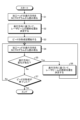
- FIG. 2 is a flowchart illustrating an example of an operation procedure of the additive manufacturing apparatus 100 according to the first embodiment.
- step S1 the additive manufacturing apparatus 100 uses the control device 1 to read the traveling direction of the processing head 10 from the NC program.
- the control device 1 analyzes the machining path based on the NC program.
- the control device 1 determines the traveling direction of the machining head 10 for each machining point that is a position in each control period on the machining path.
- step S2 the control device 1 determines the irradiation position of the laser beam 24 based on the traveling direction read in step S1. A method for determining the irradiation position will be described later.
- step S3 the additive manufacturing apparatus 100 sets the position of the laser beam 24 at the irradiation position determined in step S2, and starts forming a bead.
- step S4 the additive manufacturing apparatus 100 uses the control device 1 to read the traveling direction of the processing head 10 from the NC program.
- step S5 the control device 1 determines whether there is a change in the direction of movement of the processing head 10. The control device 1 determines whether the traveling direction read in step S4 has changed from the traveling direction read in step S1. If it is determined in step S5 that there is no change in the traveling direction (step S5, No), the additive manufacturing apparatus 100 advances the procedure to step S7.
- step S6 the control device 1 adjusts the irradiation position of the laser beam 24 based on the traveling direction read in step S4. decide.
- the additive manufacturing apparatus 100 sets the position of the laser beam 24 at the irradiation position determined in step S6, and continues forming the bead. After completing step S6, the additive manufacturing apparatus 100 returns the procedure to step S4.
- step S7 the control device 1 determines whether or not the formation of the bead that started in step S3 has been completed. If the bead formation is not completed (step S7, No), the additive manufacturing apparatus 100 returns the procedure to step S4. On the other hand, if the bead formation is completed (step S7, Yes), the additive manufacturing apparatus 100 ends the operation according to the procedure shown in FIG. The additive manufacturing apparatus 100 forms each of the beads constituting the modeled object through operations according to the procedure shown in FIG. 2 .
- the additive manufacturing apparatus 100 determines the irradiation position of the laser beam 24 before the direction of movement of the processing head 10 changes, and changes the irradiation position of the laser beam 24 in accordance with the timing at which the direction of movement of the processing head 10 changes.
- the control device 1 always reads the NC program in advance and determines the irradiation position of the laser beam 24. Pre-reading refers to analyzing a process to be executed after the process currently being executed in the analysis of the NC program.
- the speed of the processing head 10 when forming the bead is, for example, about 300 mm/min to 3000 mm/min.
- the control device 1 performs control to change the irradiation position of the laser beam 24 at intervals of approximately 20 msec.
- control device 1 sets the irradiation position of the laser beam 24 in advance with respect to the processing path generated by a computer-aided manufacturing (CAM) device, and changes the irradiation position based on the setting. Also good. For example, if it is difficult to control the irradiation position of the laser beam 24 at intervals of approximately 20 msec while reading the traveling direction of the processing head 10 from the NC program, the control device 1 may be configured to set the irradiation position in advance. , the irradiation position can be changed appropriately.
- CAM computer-aided manufacturing
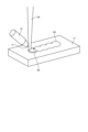
- FIG. 3 is a diagram showing how a shaped object is formed by the additive manufacturing apparatus 100 according to the first embodiment.
- FIG. 3 schematically shows how beads 35 are formed on the base material 17, which is a workpiece.
- the machining area 34 is an area where machining is performed and is centered on the machining point.
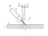
- the processing point is a position on the surface 32 of the base material 17, and is the intersection of the central axis CL of the beam nozzle 11 and the central axis CW of the wire 5 supplied from the wire nozzle 12.
- illustration of the beam nozzle 11 is omitted.
- the laser beam 24 irradiates into the processing area 34 .
- the wire 5 is supplied to the processing point.
- a molten pool 33 is formed in a portion of the surface 32 within the processing region 34.
- the melt 31 of the wire 5 is deposited onto the melt pool 33 .
- the molten material 31 and the molten pool 33 are integrated with each other, and the molten material 31 and the molten pool 33 solidify to form a bead 35 joined to the base material 17.
- the arrow 36 represents the direction of movement of the processing head 10.
- a linear bead 35 whose longitudinal direction is in the direction of the arrow 36 is formed on the base material 17.
- Arrow 37 represents the direction in which laser beam 24 is moved.
- the direction in which the laser beam 24 is moved is perpendicular to the direction in which the processing head 10 moves.
- the irradiation position of the laser beam 24 is a position shifted from the processing point in the direction of an arrow 37.
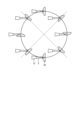
- FIG. 4 is a diagram for explaining movement of the laser beam 24 in the additive manufacturing apparatus 100 according to the first embodiment.
- angles such as 0°, 45°, ..., 315° indicate the direction of movement of the processing head 10.
- the angle indicating the direction of movement of the processing head 10 is based on the plus X direction.
- Spot 38 is a cross section of laser beam 24 at the reference plane.
- Arrow 39 represents the direction in which laser beam 24 is moved.
- FIG. 4 shows how the irradiation position of the laser beam 24 is changed depending on the direction in which the processing head 10 moves.
- the center of the spot 38 coincides with the position of the tip of the wire 5 when the traveling direction is 0° and when the traveling direction is 180°.
- the center of the spot 38 shifts forward in the traveling direction. While the traveling direction gradually changes from 0° to 90° via 45°, the direction of the arrow 39, that is, the direction in which the spot 38 is shifted gradually changes from the plus X direction to the plus Y direction. Further, the amount of shift of the center of the spot 38 from the tip of the wire 5 gradually increases from zero. The shift amount is maximum when the traveling direction is 90°.
- the traveling direction gradually changes from 90° to 135° to 180°
- the direction in which the spot 38 is shifted changes from the plus Y direction to the minus X direction.
- the shift amount gradually decreases from the maximum value of the shift amount.
- the traveling direction is 180°
- the shift amount is zero.
- the traveling direction gradually changes from 180° to 225° to 270°
- the direction in which the spot 38 is shifted changes from the minus X direction to the minus Y direction.
- the shift amount gradually increases from zero.
- the amount of shift is maximum when the traveling direction is 270°.
- the traveling direction gradually changes from 270° to 315° to 360°, that is, 0°
- the direction in which the spot 38 is shifted changes from the minus Y direction to the plus X direction.
- the shift amount gradually decreases from the maximum value of the shift amount. When the traveling direction is 0°, the shift amount is zero.
- the relationship between the direction of movement of the processing head 10 and the direction in which the laser beam 24 is moved, as described above, is set in advance in the control device 1. Based on this relationship, the control device 1 determines the direction in which the laser beam 24 is to be moved by the beam drive unit 20 from the traveling direction of the processing head 10.
- control device 1 sets the same direction as the traveling direction of the processing head 10 as the direction in which the laser beam 24 is moved by the beam drive unit 20. do. Thereby, the beam drive unit 20 moves the laser beam 24 forward in the direction in which the processing head 10 moves.
- the control device 1 determines the amount of shift of the laser beam 24 by the beam drive unit 20 from the traveling direction of the processing head 10. In this way, the control device 1 adjusts the amount of shift of the laser beam 24 from the tip of the wire 5 according to the traveling direction of the processing head 10.
- FIG. 5 is a diagram showing how the laser beam 24 is moved by the additive manufacturing apparatus 100 according to the first embodiment.
- FIG. 5 shows an example in which the direction of movement of the processing head 10 is 90°.
- the shift amount of the spot 38 is maximum. As shown in FIG. 5, by aligning the end of the wire 5 opposite to the direction of movement of the processing head 10 with the end of the spot 38 opposite to the direction of movement of the processing head 10, the shift amount of the spot 38 is is maximum.
- the diameter of the wire 5 is 1.2 mm, and the diameter of the laser beam 24 is 3.0 mm.
- the distance between the central axis CW of the wire 5 and the center of the spot 38 is 0.9 mm. That is, in the state shown in FIG. 5, the laser beam 24 is moving 0.9 mm forward from the tip of the wire 5.
- the control device 1 increases the shift amount of the laser beam 24 in stages when the traveling direction of the processing head 10 gradually changes from 0° to 90°.
- the shift amount is decreased by 0.01 mm every time the direction of movement of the processing head 10 changes by 1°.
- the control device 1 gradually reduces the shift amount of the laser beam 24 when the traveling direction of the processing head 10 gradually changes from 90° to 180°.
- the control device 1 increases the shift amount of the laser beam 24 in stages, as in the case from 0° to 90°.
- the control device 1 decreases the shift amount of the laser beam 24 in stages, as in the case from 90° to 180°.
- the wire 5 may be bent or damaged due to the tip of the wire 5 coming into contact with an insufficiently melted portion of the workpiece.
- the insufficiently melted portion may become an obstacle, inhibiting movement of the tip in the direction of the reference plane.
- the likelihood of problems occurring due to the presence of such insufficiently melted portions changes depending on the direction in which the tip of the wire 5 is moved. The closer the advancing direction of the tip of the wire 5 is perpendicular to the central axis CW of the wire 5, the more likely this problem will occur.
- the additive manufacturing apparatus 100 adjusts the irradiation position of the laser beam 24 in response to a change in the direction in which the tip of the wire 5 is moved by moving the laser beam 24 using the beam driving unit 20.
- the additive manufacturing apparatus 100 moves the laser beam 24 forward in the direction of movement of the processing head 10 to promote melting of the workpiece in the forward direction where the tip of the wire 5 is moved.
- the additive manufacturing apparatus 100 can reduce the above-mentioned problems by promoting melting of the workpiece in front of which the tip of the wire 5 is moved. This allows the additive manufacturing apparatus 100 to perform stable processing.
- the additive manufacturing apparatus 100 increases the amount of shift of the laser beam 24 as the direction of movement of the tip of the wire 5 is more perpendicular to the central axis CW of the wire 5. Accelerates melting. Thereby, the additive manufacturing apparatus 100 can more effectively reduce defects. Furthermore, the additive manufacturing apparatus 100 can perform stable processing regardless of the direction in which the tip of the wire 5 moves.
- the additive manufacturing apparatus 100 can also prevent the bead width from becoming narrower than expected due to the flow of molten metal being obstructed by the wire 5. Thereby, the additive manufacturing apparatus 100 can form the bead 35 with a desired bead width.
- the additive manufacturing apparatus 100 determines the direction in which the laser beam 24 is moved by the second drive unit based on the traveling direction of the tip of the wire 5.
- the additive manufacturing apparatus 100 controls the first drive section and the second drive section so that the laser beam 24 can be moved in a manner different from the movement of the tip of the wire 5 relative to the workpiece.
- the additive manufacturing apparatus 100 can reduce problems caused by the wire 5 coming into contact with insufficiently melted parts, and can realize stable processing. As described above, the additive manufacturing apparatus 100 has the effect of being able to realize stable processing.
- Embodiment 2 In the second embodiment, an example will be described in which the irradiation area of the laser beam 24 is expanded by moving the laser beam 24 at high speed.
- the configuration of additive manufacturing apparatus 100 according to the second embodiment is similar to the configuration of additive manufacturing apparatus 100 according to the first embodiment.
- Embodiment 2 the same components as in Embodiment 1 described above are given the same reference numerals, and operations that are different from Embodiment 1 will be mainly described.
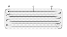
- FIG. 6 is a diagram showing how the laser beam 24 is moved by the beam driving section 20 of the additive manufacturing apparatus 100 according to the second embodiment.
- FIG. 6 shows an example in which the laser beam 24 is moved in an irradiation area 40 that is wider than the spot of the laser beam 24 on the base material 17 that is a workpiece.
- FIG. 6 schematically shows how the laser beam 24 is moved in the irradiation area 40.
- the beam driving unit 20 moves the laser beam 24 at a higher speed than the speed at which the tip of the wire 5 is moved, thereby changing the irradiation area 40 of the laser beam 24 on the workpiece. Make it bigger than the spot.
- an arrow 41 indicates an example of a path along which the laser beam 24 is moved in the irradiation region 40.
- FIG. 7 is a first diagram for explaining the irradiation area 40 in which the laser beam 24 is moved by the beam driving unit 20 of the additive manufacturing apparatus 100 according to the second embodiment.
- FIG. 8 is a second diagram for explaining the irradiation region 40 in which the laser beam 24 is moved by the beam driving unit 20 of the additive manufacturing apparatus 100 according to the second embodiment.
- the irradiation area 40 shown in FIGS. 7 and 8 has a nearly rectangular shape, with each of the four corners deformed so as to have roundness.
- FIG. 7 shows an example in which the direction of the irradiation area 40 is changed in response to a change in the direction of movement of the processing head 10.
- the orientation of the irradiation area 40 changes so that the long sides of the rectangle are perpendicular to the direction in which the tip of the wire 5 moves.
- the control device 1 determines the direction in which the laser beam 24 is moved based on the direction in which the tip of the wire 5 moves, thereby moving the irradiation area 40 according to the direction in which the tip of the wire 5 moves. Change direction.
- the control device 1 has a head drive unit 14 that is a first drive unit and a beam drive unit that is a second drive unit so that the laser beam 24 can be moved in a manner different from the movement of the tip of the wire 5 relative to the workpiece. 20. Thereby, the control device 1 moves the laser beam 24 faster than the speed at which the tip of the wire 5 is moved. Further, the control device 1 moves the laser beam 24 in a direction determined according to the traveling direction of the tip of the wire 5.
- an arrow 41 indicates an example of a path along which the laser beam 24 is moved in the irradiation region 40.
- the spot 42 of the laser beam 24 is circular and smaller than the irradiation area 40 .
- the beam driving unit 20 moves the spot 42 over the entire irradiation area 40 by reciprocating the spot 42 multiple times in the direction of the long side of the rectangle.
- the additive manufacturing apparatus 100 moves the irradiation area 40 on the workpiece by moving the processing head 10.
- the additive manufacturing apparatus 100 moves the spot 42 faster than the movement of the processing head 10 to pseudo-enlarge the spot 42 and irradiates it with the laser beam 24. Bead 35 is formed in irradiation area 40 .
- the additive manufacturing apparatus 100 can form the bead 35 in the irradiation area 40 that is wider than the spot 42.
- the additive manufacturing apparatus 100 can realize processing similar to the case where the spot 42 is expanded to the irradiation area 40 by moving the laser beam 24 by the beam driving section 20. Note that the path of the laser beam 24 in the irradiation area 40 is arbitrary and is not limited to the path shown by the arrow 41 in FIG.
- an irradiation area 40 in which the spot 42 is pseudo-enlarged can be obtained.
- the length of the irradiation area 40 in the longitudinal direction of the irradiation area 40 is 6 mm
- the moving speed of the laser beam 24 will be approximately 20 m/sec.
- the moving speed of the laser beam 24 is slower than 20 m/sec, it is possible to obtain the irradiation area 40 in which the spot 42 is expanded in a pseudo manner.
- the irradiation area 40 can be obtained.
- the moving speed of the laser beam 24 is sufficiently faster than the moving speed of the processing head 10 to the extent that energy capable of forming the molten pool 33 can be given to the irradiation region 40 by moving the laser beam 24. refers to The additive manufacturing apparatus 100 can obtain an irradiation area 40 in which the spot 42 is artificially enlarged by making the moving speed of the laser beam 24 approximately 10 to 20 times or more faster than the moving speed of the processing head 10. Can be done.
- the additive manufacturing apparatus 100 can form the bead 35 having a width of approximately 5 to 10 times the diameter of the wire 5 by forming the irradiation area 40 in which the spot 42 is artificially enlarged.
- the additive manufacturing apparatus 100 can make the energy density of the laser beam 24 higher than when expanding the diameter of the laser beam 24. For this reason, the additive manufacturing apparatus 100 can improve the processing speed when forming the bead 35 with a width wider than the diameter of the wire 5 than when expanding the diameter of the laser beam 24.
- the energy density is 3.14 times larger in the case of the rectangle.
- a circular beam is a laser beam 24 whose cross section perpendicular to the central axis of the laser beam 24 is circular.
- the irradiation area 40 is rectangular, the irradiation area 40 has anisotropy. Therefore, if the direction of the irradiation area 40 on the reference plane is constant regardless of the direction of movement of the processing head 10, the direction of movement of the processing head 10 As the width of the bead 35 changes, the width of the bead 35 also changes.
- the additive manufacturing apparatus 100 can produce images of a constant width while changing the direction of movement of the processing head 10.
- a bead 35 can be formed.
- the irradiation area 40 that pseudo-enlarges the spot 42 is not limited to a rectangle like the rectangle described above, and may have a shape other than a rectangle.
- the additive manufacturing apparatus 100 can make the irradiation area 40 into any shape by moving the laser beam 24.
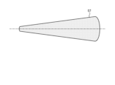
- FIG. 9 is a diagram showing a first modification of the irradiation area 40 in which the laser beam 24 is moved by the beam driving unit 20 of the additive manufacturing apparatus 100 according to the second embodiment.
- the irradiation area 43 which is a first modification of the irradiation area 40, has a rectangular shape with one long side curved, and has a shape similar to the cross section of a convex lens.
- FIG. 9 shows an example in which the direction of the irradiation area 43 is changed in response to a change in the direction of movement of the processing head 10. In the example shown in FIG. 9, the orientation of the irradiation area 43 is changed so that the longitudinal direction of the shape of the irradiation area 43 is perpendicular to the direction in which the tip of the wire 5 moves.
- the center of the irradiation area 43 coincides with the position of the tip of the wire 5 when the traveling direction is 0° and when the traveling direction is 180°.
- the center of the irradiation area 43 shifts forward in the traveling direction.
- the shift amount for moving the center of the irradiation area 43 from the tip of the wire 5 is maximum when the traveling direction is 90° and when the traveling direction is 270°.
- the beam driving unit 20 moves the irradiation area 43 forward in the direction of movement of the tip of the wire 5. That is, the beam driving section 20 moves the laser beam 24 forward in the traveling direction. Further, the control device 1 adjusts the shift amount of the center of the irradiation area 43 from the tip of the wire 5 according to the direction in which the tip of the wire 5 moves.
- the traveling direction when the traveling direction is 0°, the portion of the outer shape of the irradiation area 43 that corresponds to the plane opposite to the convex surface of the convex lens is directed forward in the traveling direction.
- the traveling direction when the traveling direction is 180°, the portion of the irradiation area 43 is directed toward the rear in the traveling direction.
- the traveling direction is 135° and when the traveling direction is 225°, the corresponding portion of the irradiation area 43 is directed backward in the traveling direction, similarly to when the traveling direction is 180°.
- the additive manufacturing apparatus 100 adjusts the orientation of the irradiation area 43 in this way when the traveling direction is between 135° and 180°.
- the additive manufacturing apparatus 100 sufficiently melts the workpiece in a portion of the irradiation area 43 where the laser beam 24 is less obstructed by the wire 5.
- the additive manufacturing apparatus 100 can form a bead 35 with a desired bead width by sufficiently melting the workpiece by adjusting the irradiation area 43 in this manner.
- the additive manufacturing apparatus 100 can reduce problems such as bending of the wire 5, breakage of the wire 5, or obstacles to the movement of the wire 5 by promoting melting of the workpiece in front of which the tip of the wire 5 is moved. This allows the additive manufacturing apparatus 100 to perform stable processing.
- By changing the shape of the irradiation area 43 from a rectangular shape changes in the area of the portion of the wire 5 that is irradiated with the laser beam 24 are reduced.
- the melting of the wire 5 is stabilized by reducing the change in the area with respect to the change in the direction of movement of the processing head 10.
- the additive manufacturing apparatus 100 can form the bead 35 with a desired width with high precision.
- FIG. 10 is a diagram showing a second modified example of the irradiation area 40 in which the laser beam 24 is moved by the beam driving unit 20 of the additive manufacturing apparatus 100 according to the second embodiment.
- the irradiation area 44 which is a second modification of the irradiation area 40, has a so-called horseshoe shape.
- FIG. 10 shows an example in which the shape of the irradiation area 44 is changed in response to a change in the direction of movement of the processing head 10. In the example shown in FIG. 10, the shape of the irradiation area 44 changes so that the area of the portion of the wire 5 that is irradiated with the laser beam 24 is constant.
- the area of the portion of the wire 5 irradiated by the laser beam 24 is constant, so that the melting of the wire 5 is stabilized.
- the additive manufacturing apparatus 100 can separate the front end of the wire 5 in the direction of movement of the processing head 10 and the rear end of the wire 5 in the direction of movement of the processing head 10. Both can be sufficiently melted.
- the additive manufacturing apparatus 100 can form the bead 35 with a desired width with high precision.
- the additive manufacturing apparatus 100 can set the area of the portion of the wire 5 irradiated with the laser beam 24 to an arbitrary area by appropriately changing the shape of the irradiation area 44 .
- the additive manufacturing apparatus 100 can arbitrarily set the area of the portion of the wire 5 that is irradiated with the laser beam 24 depending on the amount of material desired to be melted.
- the additive manufacturing apparatus 100 can make the irradiation region 40 have an arbitrary shape by appropriately setting the path along which the laser beam 24 is moved by the beam driving unit 20.
- the irradiation area 40 may be, for example, circular with a diameter larger than the diameter of the laser beam 24.
- the additive manufacturing apparatus 100 can easily form a bead 35 of any width by appropriately setting the shape of the irradiation area 40.
- the additive manufacturing apparatus 100 can form a bead 35 of any width without increasing the diameter of the laser beam 24. That is, the additive manufacturing apparatus 100 can form a bead 35 of any width using the laser beam 24 with a small diameter.
- the first advantage is that, as described above, the shape of the irradiation area 40 can be set appropriately, so that the bead 35 with a desired width can be formed with high precision.
- the second advantage is that by increasing the energy density of the laser beam 24, it is possible to form objects using highly reflective materials such as copper, gold, or silver.
- Equation (1) shown below is a temperature rise equation during one-pulse processing using a circular heat source.
- ⁇ represents temperature
- A heat absorption rate
- P represents average power
- a represents spot radius
- K thermal conductivity
- J 0 represents a zero-order Bessel function of the first kind
- J 1 represents a first-order Bessel function of the first kind
- r represents a measurement distance
- t represents an irradiation time.
- a beam diameter of 0.5 mm is too small when using typical metal wires with a diameter of 1 mm or more. For this reason, a beam with a beam diameter of 0.5 mm could not be used for processing using the typical metal wire.
- the additive manufacturing apparatus 100 can form a shaped object using the wire 5 made of a highly reflective material.
- the additive manufacturing apparatus 100 can perform modeling using a highly reflective material using a laser used in conventional additive manufacturing without using a special high-output laser.
- the additive manufacturing apparatus 100 moves the laser beam 24 at a higher speed than the speed at which the tip of the wire 5 is moved, thereby moving the irradiation area 40 of the laser beam 24 on the workpiece from the spot 42. Also expand. Thereby, the additive manufacturing apparatus 100 can form the bead 35 with a desired width with high precision. Further, since the additive manufacturing apparatus 100 can use the laser beam 24 having a diameter smaller than the diameter of the wire 5, it is possible to form a model using the wire 5 made of a highly reflective material.
- Embodiment 3 an example will be described in which a modeled object is formed by switching between fine modeling and coarse modeling.
- the configuration of additive manufacturing apparatus 100 according to the third embodiment is similar to the configuration of additive manufacturing apparatus 100 according to the first embodiment.
- Embodiment 3 the same components as in Embodiment 1 or 2 described above are given the same reference numerals, and operations that are different from Embodiment 1 or 2 will be mainly described.
- FIG. 11 is a diagram showing how a shaped object is formed by the additive manufacturing apparatus 100 according to the third embodiment.
- the additive manufacturing apparatus 100 switches between fine modeling and rough modeling for each part of the workpiece by adjusting the amount of movement of the laser beam 24 by the beam drive unit 20 for each part of the workpiece.
- Microfabrication is a modeling that emphasizes increasing the shape accuracy of a modeled object rather than increasing the processing speed.
- Rough modeling is modeling that emphasizes increasing the processing speed rather than increasing the shape accuracy of the modeled object.
- An arrow 53 indicates that the laser beam 24 is moved by the beam driver 20.
- Arrow 54 represents the direction in which processing head 10 moves.
- the bead 51 is a bead 35 formed by fine modeling.
- the bead 52 is the bead 35 formed by rough shaping. Compared to the bead 52, the bead 51 has a smaller bead width in the direction of movement of the processing head 10.
- the beam driving unit 20 makes the size of the irradiation area 40 different at different positions on the reference plane of the workpiece.
- the beam driving unit 20 makes the width of the irradiation area 40 smaller at each of both ends of the workpiece in the direction of movement of the processing head 10 than at other parts of the workpiece. .
- the beam driving unit 20 adjusts the width of the irradiation area 40 by adjusting the amount of movement of the laser beam 24 in the direction of movement of the processing head 10.
- the beam drive unit 20 adjusts the width of the irradiation area 40 by adjusting the width of the reciprocating laser beam 24 in the traveling direction of the processing head 10.
- the additive manufacturing apparatus 100 adjusts the bead width of the formed bead 35 by adjusting the width of the irradiation area 40.
- the additive manufacturing apparatus 100 forms beads 51 on each of both ends of the workpiece by adjusting the bead width according to the position of the workpiece, and forms beads 51 on the parts of the workpiece other than both ends. forms a bead 52.
- the additive manufacturing apparatus 100 changes the size of the irradiation area 40 depending on the position on the workpiece by adjusting the width of the irradiation area 40 depending on the position on the reference plane of the workpiece. .
- the additive manufacturing apparatus 100 changes the size of the irradiation area 40 depending on the position on the workpiece, thereby switching between forming the bead 51 and forming the bead 52 depending on the position on the workpiece.
- the additive manufacturing apparatus 100 can form a shaped object with a highly accurate outer shape by performing fine modeling on both ends of the shaped object. Furthermore, the additive manufacturing apparatus 100 can shorten the processing time for the entire shaped object by rough modeling of the parts other than both ends of the shaped object.
- FIG. 12 is a diagram for explaining the shapes of beads 51 and 52 formed by the additive manufacturing apparatus 100 according to the third embodiment.
- FIG. 12 shows a cross section of the bead 51 and a cross section of the bead 52. These cross sections include the traveling direction of the processing head 10 and the central axis CL of the beam nozzle 11.
- the bead width of the bead 51 is w 1
- the cross-sectional area of the bead 51 is M 1
- the bead width of the bead 52 is w 2
- the cross-sectional area of the bead 52 is M 2
- the height of the beads 51 and 52 in the direction of the central axis CL is When h is assumed, the following equations (2) and (3) hold true.
- M1 w1 /2 ⁇ h/2 ⁇ ...(2)
- M2 w2 /2 ⁇ h/2 ⁇ ...(3)
- the forming speed WFR which is the speed at which the additive manufacturing apparatus 100 forms the bead 51 or the bead 52, is determined by the following equation (4).
- F is the speed at which the laser beam 24 is moved by the beam drive section 20.
- WFR (cc/h) F (mm/min) x M i (mm 2 ) x 60 (min) x 1000 (4)
- the modeling speed WFR in rough modeling can be approximately six times the modeling speed WFR in fine modeling.
- the additive manufacturing apparatus 100 uses fine modeling to process parts that require high shape accuracy, and applies coarse modeling to other parts, thereby achieving high-speed modeling while maintaining shape accuracy. can be realized.
- the additive manufacturing apparatus 100 increases the amount of heat input for melting the wire 5 by increasing at least one of the laser output of the laser oscillator 2 and the amount of current flowing from the hot wire power source 21 to the wire 5. Thereby, the additive manufacturing apparatus 100 can sufficiently melt the wire 5 and achieve a high processing speed for the portion where rough modeling is performed.
- control device 1 may determine the direction in which the laser beam 24 is moved by the beam drive unit 20 based on the traveling direction of the tip of the wire 5.
- the additive manufacturing apparatus 100 makes the size of the irradiation area 40 different at different positions on the reference plane of the workpiece.
- the additive manufacturing apparatus 100 can switch between fine modeling and rough modeling depending on the position of the workpiece on the reference plane.
- the additive manufacturing apparatus 100 can arbitrarily set whether to perform processing that emphasizes shape accuracy or processing that emphasizes processing speed for each part of the shaped object. Thereby, the additive manufacturing apparatus 100 can realize high-speed modeling of a shaped object while maintaining shape accuracy.
- Embodiment 4 an example will be described in which the width of reciprocating the laser beam 24 within the irradiation area 40 is changed.
- the configuration of additive manufacturing apparatus 100 according to the fourth embodiment is similar to the configuration of additive manufacturing apparatus 100 according to the first embodiment.
- Embodiment 4 the same components as in Embodiments 1 to 3 described above are given the same reference numerals, and operations that are different from Embodiments 1 to 3 will be mainly described.
- FIG. 13 is a diagram showing how the laser beam 24 is moved by the additive manufacturing apparatus 100 according to the fourth embodiment.
- the beam driving unit 20 moves the laser beam 24 at a higher speed than the speed at which the tip of the wire 5 is moved, thereby changing the irradiation area 55 of the laser beam 24 on the workpiece. Make it bigger than the spot.
- the irradiation area 55 is an example of the irradiation area 40 in the case where the width of the reciprocating laser beam 24 is changed.
- an arrow 56 indicates an example of a path along which the laser beam 24 is moved in the irradiation area 55.
- the beam driving unit 20 causes the laser beam 24 to reciprocate within the irradiation area 55 and gradually changes the width of the reciprocating width of the laser beam 24 within the irradiation area 55.
- the beam driver 20 reduces the width of the reciprocating laser beam 24 as the laser beam 24 approaches the tip of the wire 5.
- the irradiation area 55 has a shape in which the width in the direction in which the laser beam 24 is reciprocated changes continuously.
- the additive manufacturing apparatus 100 forms a bead 35 having a shape in which the width continuously changes.
- FIG. 14 is a diagram showing a bead 57 formed in the fourth embodiment.
- FIG. 15 is a diagram showing a bead 58 formed in a comparative example of the fourth embodiment.
- the bead 57 shown in FIG. 14 is an example of the bead 35 formed in the fourth embodiment and having a shape in which the width changes continuously.
- the bead 58 shown in FIG. 15 is a combination of a plurality of wire beads and is formed by a method different from that of the fourth embodiment.
- Line beads are linear beads.
- the additive manufacturing apparatus 100 can realize modeling with high shape reproducibility by gradually changing the width of the reciprocating laser beam 24 within the irradiation area 55.
- the irradiation area 55 can be made into any shape by appropriately setting the path along which the laser beam 24 is moved by the beam driving unit 20. Also in the fourth embodiment, the control device 1 may determine the direction in which the laser beam 24 is moved by the beam drive unit 20 based on the traveling direction of the tip of the wire 5.
- Embodiment 5 an example in which a shaped object is formed using ball beads will be described. A ball bead is a dotted bead.
- the configuration of additive manufacturing apparatus 100 according to the fifth embodiment is similar to the configuration of additive manufacturing apparatus 100 according to the first embodiment.
- Embodiment 5 the same components as in Embodiments 1 to 4 described above are given the same reference numerals, and operations that are different from Embodiments 1 to 4 will be mainly described.
- FIG. 16 is a diagram showing how a shaped object is formed by the additive manufacturing apparatus 100 according to the fifth embodiment.
- the additive manufacturing apparatus 100 forms a shaped object using beads 61 that are ball beads.
- Arrow 62 represents movement of laser beam 24 by beam driver 20 .
- An arrow 63 represents the direction in which the processing head 10 moves.
- the beam driving section 20, which is the second driving section, moves the laser beam 24 in a direction included in the reference plane.
- the control device 1 controls the beam driving unit 20 to move the laser beam 24 in a direction included in the reference plane.
- FIG. 17 is a first diagram showing how the laser beam 24 is moved by the beam driving section 20 of the additive manufacturing apparatus 100 according to the fifth embodiment.
- FIG. 17 shows an example in which the laser beam 24 is moved in an irradiation area 64 that is wider than the spot of the laser beam 24 on the base material 17 that is a workpiece.
- FIG. 17 schematically shows how the laser beam 24 is moved in the irradiation area 64.
- An arrow 65 shown in FIG. 17 represents a path along which the laser beam 24 is moved in the irradiation area 64.
- the beam driving unit 20 moves the laser beam 24 to enlarge the irradiation area 64 of the laser beam 24 on the workpiece compared to the spot of the laser beam 24 .
- a plurality of irradiation areas 64 are lined up in the direction of movement of the processing head 10.
- Each irradiation area 64 is circular.
- a bead 61 is formed in each irradiation area 64.
- a bead 61 having a circular shape on the reference plane is formed on the workpiece.
- the additive manufacturing apparatus 100 according to the fifth embodiment is not limited to one in which the entire shaped object is formed of ball beads.
- the additive manufacturing apparatus 100 may be any device that forms beads constituting a shaped article on at least a portion of the shaped article.
- FIG. 18 is a second diagram showing how the laser beam 24 is moved by the beam driving unit 20 of the additive manufacturing apparatus 100 according to the fifth embodiment.
- FIG. 18 shows an example in which the laser beam 24 is moved in an irradiation area 66 having a different shape from the irradiation area 64 shown in FIG.
- FIG. 18 schematically shows how the laser beam 24 is moved in the irradiation area 66.
- An arrow 67 shown in FIG. 18 represents a path along which the laser beam 24 is moved in the irradiation area 66.
- a plurality of irradiation areas 66 are lined up in the direction of movement of the processing head 10.
- Each irradiation area 66 is elliptical.
- a bead 61 is formed in each irradiation area 66.
- a bead 61 having an elliptical shape on the reference plane is formed on the workpiece.
- the additive manufacturing apparatus 100 can form beads 61 of any shape by appropriately setting the shapes of the irradiation areas 64 and 66.
- FIG. 19 is a diagram for explaining the first step of forming a bead by the additive manufacturing apparatus 100 according to the fifth embodiment.
- the additive manufacturing apparatus 100 moves the processing head 10 to align the central axis CL of the laser beam 24 with the center of the processing area 34 .
- FIG. 20 is a diagram for explaining the second step of forming a bead by the additive manufacturing apparatus 100 according to the fifth embodiment.
- the additive manufacturing apparatus 100 sends out the wire 5 from the wire nozzle 12 to the processing area 34 to bring the tip of the wire 5 into contact with the surface 32 of the base material 17.
- the central axis CL of the beam nozzle 11 and the central axis CW of the wire 5 intersect at the surface 32.
- FIG. 21 is a diagram for explaining the third step of forming a bead by the additive manufacturing apparatus 100 according to the fifth embodiment.
- the additive manufacturing apparatus 100 irradiates the processing area 34 with a laser beam 24 .
- the beam driving section 20 moves the laser beam 24 within the irradiation areas 64 and 66.
- the additive manufacturing apparatus 100 starts injecting the inert gas 25 from the gas nozzle 13 to the processing area 34 in accordance with the irradiation of the laser beam 24.
- the additive manufacturing apparatus 100 may inject the inert gas 25 at a predetermined time before starting irradiation with the laser beam 24. Thereby, the additive manufacturing apparatus 100 can start injection of the inert gas 25 after removing the active gas such as oxygen remaining in the gas nozzle 13 from inside the gas nozzle 13.
- FIG. 22 is a diagram for explaining the fourth step of forming a bead by the additive manufacturing apparatus 100 according to the fifth embodiment.
- Additive manufacturing apparatus 100 supplies wire 5 from wire nozzle 12 toward surface 32 . Thereby, the additive manufacturing apparatus 100 starts supplying the wire 5 to the processing area 34.
- a molten pool 33 is formed in a portion of the surface 32 within the processing region 34.
- the melt 31 of the wire 5 is deposited onto the melt pool 33 .
- the molten material 31 and the molten pool 33 are integrated with each other, and the molten material 31 and the molten pool 33 solidify to form a bead 61 joined to the base material 17.
- the additive manufacturing apparatus 100 starts supplying the wire 5 to the processing area 34 and then continues supplying the wire 5 for a predetermined supply time.
- the additive manufacturing apparatus 100 adjusts the feeding speed of the wire 5 by adjusting the rotational speed of the rotary motor 4. There is a correlation between the feeding speed of the wire 5 and the laser output in order to achieve proper welding of the melt 31. Based on this correlation, the feeding speed of the wire 5 is set to a certain limit depending on the laser output.
- the time required to form the bead 61 can be shortened. Note that if the feeding speed of the wire 5 is too high relative to the laser output, the wire 5 remains unmelted. Further, when the feeding speed of the wire 5 is slow relative to the laser output, the wire 5 is heated excessively, and droplets of the melt 31 fall from the wire 5. The falling droplets may cause the melt 31 to solidify into a shape different from the desired shape of the bead 61. By appropriately adjusting the feeding speed of the wire 5, the additive manufacturing apparatus 100 can prevent the wire 5 from remaining unmelted or the droplets from falling.
- the size of the bead 61 is adjusted by changing at least one of the supply time of the wire 5, the irradiation time during which the laser beam 24 continues to be irradiated, and the amount of movement of the laser beam 24.
- the additive manufacturing apparatus 100 can increase the diameter of the formed bead 61 by increasing the supply time of the wire 5, by increasing the irradiation time of the laser beam 24, or by increasing the amount of movement of the laser beam 24. Can be done.
- the additive manufacturing apparatus 100 can reduce the diameter of the formed bead 61 by shortening the feeding time of the wire 5, shortening the irradiation time of the laser beam 24, or reducing the amount of movement of the laser beam 24. Can be done.
- the additive manufacturing apparatus 100 can adjust the shape of the bead 61 by appropriately adjusting the amount of movement of the laser beam 24.
- the additive manufacturing apparatus 100 can adjust the shape of the bead 61 to be circular or oval.
- FIG. 23 is a diagram for explaining the fifth step of forming a bead by the additive manufacturing apparatus 100 according to the fifth embodiment.
- the additive manufacturing apparatus 100 pulls out the wire 5 from the processing area 34 after the amount of melt 31 necessary to form the bead 61 is placed on the molten pool 33 .
- FIG. 24 is a diagram for explaining the sixth step of forming a bead by the additive manufacturing apparatus 100 according to the fifth embodiment.
- the additive manufacturing apparatus 100 stops irradiating the processing area 34 with the laser beam 24 . After stopping the irradiation of the laser beam 24, the additive manufacturing apparatus 100 continues to inject the inert gas 25 for a predetermined period of time.
- the duration for which the injection of the inert gas 25 is continued is the time required to lower the temperature of the bead 61 to a predetermined temperature.
- the duration is determined based on various conditions such as the material of the wire 5 or the size of the bead 61. Information on the duration is stored in the control device 1 in advance.
- the additive manufacturing apparatus 100 stops the injection of the inert gas 25 after the duration time has elapsed after stopping the irradiation of the laser beam 24 . This completes the formation of one bead 61.
- FIG. 25 is a diagram for explaining the seventh step of forming a bead by the additive manufacturing apparatus 100 according to the fifth embodiment.
- the additive manufacturing apparatus 100 moves the processing head 10 to the next processing point.
- An arrow 63 shown in FIG. 25 represents the direction in which the processing head 10 moves.
- the additive manufacturing apparatus 100 forms a shaped object by repeating the first step to the seventh step.
- the wire 5 is sent out from the wire nozzle 12 to the processing area 34, and then the laser beam 24 is irradiated toward the processing area 34.
- the additive manufacturing apparatus 100 may irradiate the laser beam 24 toward the processing area 34 and then send out the wire 5 from the wire nozzle 12 to the processing area 34.
- FIG. 26 is a diagram for explaining the eighth step of forming a bead by the additive manufacturing apparatus 100 according to the fifth embodiment.
- FIG. 27 is a diagram for explaining the ninth step of forming a bead by the additive manufacturing apparatus 100 according to the fifth embodiment.
- FIG. 28 is a diagram for explaining the tenth step of forming a bead by the additive manufacturing apparatus 100 according to the fifth embodiment.
- the additive manufacturing apparatus 100 may perform the eighth step to the tenth step instead of the second step and third step described above.
- the additive manufacturing apparatus 100 irradiates the processing area 34 with the laser beam 24 in the eighth step.
- the additive manufacturing apparatus 100 moves the laser beam 24 in the ninth step, as shown in FIG.
- the beam driving section 20 moves the laser beam 24 within the irradiation areas 64 and 66.
- the additive manufacturing apparatus 100 moves the laser beam 24 from the state shown in FIG. 26.
- the additive manufacturing apparatus 100 sends out the wire 5 from the wire nozzle 12 to the processing area 34 to bring the tip of the wire 5 into contact with the surface 32 of the base material 17. .
- the additive manufacturing apparatus 100 performs the operations from the fourth step onwards.
- the additive manufacturing apparatus 100 irradiates the laser beam 24 and moves the laser beam 24 within the irradiation areas 64 and 66, and then sends out the wire 5 to the processing area 34. .
- the additive manufacturing apparatus 100 starts feeding out the wire 5 after forming the molten pool 33 on the surface 32.
- the additive manufacturing apparatus 100 moves the laser beam 24 within the irradiation areas 64 and 66 when forming a bead.
- the additive manufacturing apparatus 100 can form a shaped object using beads of any shape.
- the additive manufacturing apparatus 100 can form objects with high precision by forming objects using bead beads of arbitrary shapes.
- the irradiation areas 64 and 66 can be made into any shape by appropriately setting the path along which the laser beam 24 is moved by the beam drive unit 20.
- the control device 1 may determine the direction in which the laser beam 24 is moved by the beam drive unit 20 based on the traveling direction of the tip of the wire 5.
- the control device 1 may determine the orientation of the irradiation areas 64, 66 or the shape of the irradiation areas 64, 66 based on the traveling direction.
- the beam driving unit 20 may make the irradiation areas 64 and 66 different in size at different positions on the reference plane of the workpiece.
- the additive manufacturing apparatus 100 according to the fifth embodiment is not limited to one in which the entire shaped object is formed from bead beads.
- the additive manufacturing apparatus 100 according to the fifth embodiment when manufacturing a shaped article by adding a material melted by the irradiation of the laser beam 24 to the workpiece, removes the beads constituting the shaped article from among the shaped articles. Any material may be used as long as it is formed on at least a part of.
- the control device 1 is realized by a processing circuit.
- the processing circuit may be a circuit on which a processor executes software, or may be a dedicated circuit.
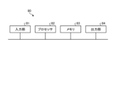
- FIG. 29 is a diagram showing a configuration example of control circuit 80 according to the first to fifth embodiments.
- the control circuit 80 includes an input section 81, a processor 82, a memory 83, and an output section 84.
- the input unit 81 is an interface circuit that receives data input from outside the control circuit 80 and provides it to the processor 82.
- the output unit 84 is an interface circuit that sends data from the processor 82 or memory 83 to the outside of the control circuit 80.
- the processing circuit is the control circuit 80 shown in FIG. 29, the functions of the control device 1 are realized by the processor 82 reading and executing a program stored in the memory 83.
- the memory 83 is also used as temporary memory in each process performed by the processor 82.
- the processor 82 is a CPU (Central Processing Unit, also referred to as a central processing unit, processing unit, arithmetic unit, microprocessor, microcomputer, processor, or DSP (Digital Signal Processor)).
- the memory 83 is, for example, RAM (Random Access Memory), ROM (Read Only Memory), flash memory, EPROM (Erasable Programmable Read Only Memory), EEPROM (registered trademark) (Electrically Erasable Programmable Read Only Memory). ), etc., non-volatile Alternatively, volatile semiconductor memory, magnetic disk, flexible disk, optical disk, compact disk, mini disk, DVD (Digital Versatile Disc), etc. are applicable.
- FIG. 29 is an example of hardware when the control device 1 is realized by a general-purpose processor 82 and a memory 83, the control device 1 may be realized by a dedicated hardware circuit.
- FIG. 30 is a diagram showing a configuration example of the dedicated hardware circuit 85 according to the first to fifth embodiments.
- the dedicated hardware circuit 85 includes an input section 81, an output section 84, and a processing circuit 86.
- the processing circuit 86 is a single circuit, a composite circuit, a programmed processor, a parallel programmed processor, an ASIC (Application Specific Integrated Circuit), an FPGA (Field Programmable Gate Array), or a combination thereof. Note that the control device 1 may be realized by combining the control circuit 80 and the hardware circuit 85.
Landscapes
- Engineering & Computer Science (AREA)
- Physics & Mathematics (AREA)
- Optics & Photonics (AREA)
- Mechanical Engineering (AREA)
- Plasma & Fusion (AREA)
- Chemical & Material Sciences (AREA)
- Manufacturing & Machinery (AREA)
- Materials Engineering (AREA)
- Automation & Control Theory (AREA)
- Laser Beam Processing (AREA)
Priority Applications (5)
| Application Number | Priority Date | Filing Date | Title |
|---|---|---|---|
| JP2022560844A JP7345679B1 (ja) | 2022-06-21 | 2022-06-21 | 付加製造装置および付加製造方法 |
| PCT/JP2022/024755 WO2023248357A1 (ja) | 2022-06-21 | 2022-06-21 | 付加製造装置および付加製造方法 |
| CN202280085512.5A CN118475429B (zh) | 2022-06-21 | 2022-06-21 | 附加制造装置及附加制造方法 |
| US18/717,531 US12533730B2 (en) | 2022-06-21 | 2022-06-21 | Additive manufacturing apparatus and additive manufacturing method |
| DE112022004908.1T DE112022004908B4 (de) | 2022-06-21 | 2022-06-21 | Vorrichtung zum additiven Herstellen und Verfahren zum additiven Herstellen |
Applications Claiming Priority (1)
| Application Number | Priority Date | Filing Date | Title |
|---|---|---|---|
| PCT/JP2022/024755 WO2023248357A1 (ja) | 2022-06-21 | 2022-06-21 | 付加製造装置および付加製造方法 |
Publications (1)
| Publication Number | Publication Date |
|---|---|
| WO2023248357A1 true WO2023248357A1 (ja) | 2023-12-28 |
Family
ID=87972041
Family Applications (1)
| Application Number | Title | Priority Date | Filing Date |
|---|---|---|---|
| PCT/JP2022/024755 Ceased WO2023248357A1 (ja) | 2022-06-21 | 2022-06-21 | 付加製造装置および付加製造方法 |
Country Status (5)
| Country | Link |
|---|---|
| US (1) | US12533730B2 (https=) |
| JP (1) | JP7345679B1 (https=) |
| CN (1) | CN118475429B (https=) |
| DE (1) | DE112022004908B4 (https=) |
| WO (1) | WO2023248357A1 (https=) |
Cited By (2)
| Publication number | Priority date | Publication date | Assignee | Title |
|---|---|---|---|---|
| JP7551045B1 (ja) * | 2024-03-12 | 2024-09-13 | 三菱電機株式会社 | 加工ヘッド、付加製造装置および付加製造方法 |
| WO2025224817A1 (ja) * | 2024-04-23 | 2025-10-30 | 三菱電機株式会社 | 金属積層構造体の製造方法及び金属積層構造体の製造装置 |
Citations (4)
| Publication number | Priority date | Publication date | Assignee | Title |
|---|---|---|---|---|
| JPH0615890U (ja) * | 1992-08-03 | 1994-03-01 | 三菱重工業株式会社 | ワイヤガイドノズル案内装置 |
| JP2000317666A (ja) * | 1999-05-12 | 2000-11-21 | Komatsu Ltd | レーザ溶接装置 |
| WO2019198212A1 (ja) * | 2018-04-12 | 2019-10-17 | 三菱電機株式会社 | 付加製造装置、付加製造システムおよび付加製造方法 |
| WO2020084715A1 (ja) * | 2018-10-24 | 2020-04-30 | 三菱電機株式会社 | 積層造形方法、加工経路生成方法および積層造形装置 |
Family Cites Families (14)
| Publication number | Priority date | Publication date | Assignee | Title |
|---|---|---|---|---|
| JP2000005888A (ja) * | 1998-06-24 | 2000-01-11 | Toyota Motor Corp | レーザ突合せ溶接方法 |
| JP2001058285A (ja) * | 1999-08-20 | 2001-03-06 | Shin Meiwa Ind Co Ltd | レーザ溶接用光学ヘッド |
| JP6983087B2 (ja) | 2018-03-07 | 2021-12-17 | 三菱重工業株式会社 | 積層造形装置 |
| US11331755B2 (en) * | 2018-10-24 | 2022-05-17 | Mitsubishi Electric Corporation | Additive manufacturing apparatus and numerical control device |
| US11305366B2 (en) | 2019-01-04 | 2022-04-19 | Lincoln Global, Inc. | Systems and methods providing dynamic bead spacing and weave fill in additive manufacturing |
| CN109702342B (zh) * | 2019-01-30 | 2024-06-11 | 华工法利莱切焊系统工程有限公司 | 铝合金激光焊接方法 |
| JP6616539B1 (ja) | 2019-02-15 | 2019-12-04 | Necプラットフォームズ株式会社 | 清掃可能化装置、清掃装置及び磁気テープ装置 |
| JP7289509B2 (ja) | 2019-04-26 | 2023-06-12 | デルタ工業株式会社 | レーザ溶接方法およびレーザ溶接装置 |
| CN114040827B (zh) * | 2019-07-08 | 2023-06-09 | 三菱电机株式会社 | 增材制造装置 |
| US20230061492A1 (en) | 2020-01-21 | 2023-03-02 | Ipg Photonics Corporation | System and method for laser metal powder deposition |
| JP2021115625A (ja) * | 2020-01-29 | 2021-08-10 | 三菱電機株式会社 | 積層造形装置、積層造形方法及び加工経路生成方法 |
| US20230131125A1 (en) | 2020-04-23 | 2023-04-27 | Mitsubishi Electric Corporation | Additive manufacturing apparatus, additive manufacturing method, and machine learning device |
| JP7382912B2 (ja) * | 2020-08-11 | 2023-11-17 | 三菱電機株式会社 | 付加製造装置および付加製造方法 |
| CN115485096B (zh) | 2020-11-17 | 2023-08-22 | 三菱电机株式会社 | 附加制造装置及附加制造方法 |
-
2022
- 2022-06-21 DE DE112022004908.1T patent/DE112022004908B4/de active Active
- 2022-06-21 JP JP2022560844A patent/JP7345679B1/ja active Active
- 2022-06-21 CN CN202280085512.5A patent/CN118475429B/zh active Active
- 2022-06-21 US US18/717,531 patent/US12533730B2/en active Active
- 2022-06-21 WO PCT/JP2022/024755 patent/WO2023248357A1/ja not_active Ceased
Patent Citations (4)
| Publication number | Priority date | Publication date | Assignee | Title |
|---|---|---|---|---|
| JPH0615890U (ja) * | 1992-08-03 | 1994-03-01 | 三菱重工業株式会社 | ワイヤガイドノズル案内装置 |
| JP2000317666A (ja) * | 1999-05-12 | 2000-11-21 | Komatsu Ltd | レーザ溶接装置 |
| WO2019198212A1 (ja) * | 2018-04-12 | 2019-10-17 | 三菱電機株式会社 | 付加製造装置、付加製造システムおよび付加製造方法 |
| WO2020084715A1 (ja) * | 2018-10-24 | 2020-04-30 | 三菱電機株式会社 | 積層造形方法、加工経路生成方法および積層造形装置 |
Cited By (4)
| Publication number | Priority date | Publication date | Assignee | Title |
|---|---|---|---|---|
| JP7551045B1 (ja) * | 2024-03-12 | 2024-09-13 | 三菱電機株式会社 | 加工ヘッド、付加製造装置および付加製造方法 |
| WO2025191699A1 (ja) * | 2024-03-12 | 2025-09-18 | 三菱電機株式会社 | 加工ヘッド、付加製造装置および付加製造方法 |
| WO2025224817A1 (ja) * | 2024-04-23 | 2025-10-30 | 三菱電機株式会社 | 金属積層構造体の製造方法及び金属積層構造体の製造装置 |
| JP7817454B1 (ja) * | 2024-04-23 | 2026-02-18 | 三菱電機株式会社 | 金属積層構造体の製造装置 |
Also Published As
| Publication number | Publication date |
|---|---|
| DE112022004908B4 (de) | 2025-12-04 |
| CN118475429A (zh) | 2024-08-09 |
| DE112022004908T5 (de) | 2024-08-14 |
| US20240416420A1 (en) | 2024-12-19 |
| CN118475429B (zh) | 2025-06-17 |
| US12533730B2 (en) | 2026-01-27 |
| JPWO2023248357A1 (https=) | 2023-12-28 |
| JP7345679B1 (ja) | 2023-09-15 |
Similar Documents
| Publication | Publication Date | Title |
|---|---|---|
| JP6719691B1 (ja) | 付加製造装置 | |
| US10583529B2 (en) | Additive manufacturing method using a plurality of synchronized laser beams | |
| JP5008260B2 (ja) | 三次元製品の製造装置及び製造方法 | |
| JP4639087B2 (ja) | 三次元製品の製造装置及び製造方法 | |
| JP5095917B2 (ja) | 三次元製品の製造装置及び製造方法 | |
| JP7345679B1 (ja) | 付加製造装置および付加製造方法 | |
| JP7733087B2 (ja) | レーザ溶接方法 | |
| US20170173883A1 (en) | Additive manufacturing method using tilted scanners | |
| US20170173736A1 (en) | Additive manufacturing method using large and small beam sizes | |
| JP2003127238A (ja) | 充填走査がインターリーブ化された選択的レーザ焼結 | |
| CN111417486A (zh) | 层叠造型物的设计方法、制造方法、制造装置、以及程序 | |
| JP7010308B2 (ja) | 処理装置及び処理方法 | |
| JP2002530710A (ja) | レーザービームを使用して物体の一領域を走査する装置及びその方法 | |
| CN110603119B (zh) | 附加制造装置、附加制造系统及附加制造方法 | |
| JP7186898B2 (ja) | 積層造形装置 | |
| CN112867579A (zh) | 附加制造装置及附加制造方法 | |
| JP2021115625A (ja) | 積層造形装置、積層造形方法及び加工経路生成方法 | |
| CN110621425A (zh) | 用于增材制造的三角形影线图案 | |
| CN115697623A (zh) | 汇流条以及汇流条的制造方法 | |
| JPWO2020084716A1 (ja) | 付加製造装置および数値制御装置 | |
| CN110573278A (zh) | 用于影线图案的直角边消除策略 | |
| JP6123469B2 (ja) | レーザ切断材料の製造方法及びレーザ切断方法 | |
| JP2011161452A (ja) | レーザー溶接方法及びレーザー溶接装置 | |
| CN114423546A (zh) | Am装置 | |
| JPWO2023248357A5 (https=) |
Legal Events
| Date | Code | Title | Description |
|---|---|---|---|
| ENP | Entry into the national phase |
Ref document number: 2022560844 Country of ref document: JP Kind code of ref document: A |
|
| 121 | Ep: the epo has been informed by wipo that ep was designated in this application |
Ref document number: 22947919 Country of ref document: EP Kind code of ref document: A1 |
|
| WWE | Wipo information: entry into national phase |
Ref document number: 18717531 Country of ref document: US |
|
| WWE | Wipo information: entry into national phase |
Ref document number: 112022004908 Country of ref document: DE |
|
| WWE | Wipo information: entry into national phase |
Ref document number: 202280085512.5 Country of ref document: CN |
|
| WWG | Wipo information: grant in national office |
Ref document number: 202280085512.5 Country of ref document: CN |
|
| 122 | Ep: pct application non-entry in european phase |
Ref document number: 22947919 Country of ref document: EP Kind code of ref document: A1 |
|
| WWG | Wipo information: grant in national office |
Ref document number: 112022004908 Country of ref document: DE |
|
| WWG | Wipo information: grant in national office |
Ref document number: 18717531 Country of ref document: US |