WO2023243244A1 - 水処理方法、水処理装置、スライム抑制剤、および洗浄方法 - Google Patents
水処理方法、水処理装置、スライム抑制剤、および洗浄方法 Download PDFInfo
- Publication number
- WO2023243244A1 WO2023243244A1 PCT/JP2023/016864 JP2023016864W WO2023243244A1 WO 2023243244 A1 WO2023243244 A1 WO 2023243244A1 JP 2023016864 W JP2023016864 W JP 2023016864W WO 2023243244 A1 WO2023243244 A1 WO 2023243244A1
- Authority
- WO
- WIPO (PCT)
- Prior art keywords
- water
- iodine
- treated
- oxidizing agent
- chamber
- Prior art date
- Legal status (The legal status is an assumption and is not a legal conclusion. Google has not performed a legal analysis and makes no representation as to the accuracy of the status listed.)
- Ceased
Links
Images




Classifications
-
- C—CHEMISTRY; METALLURGY
- C02—TREATMENT OF WATER, WASTE WATER, SEWAGE, OR SLUDGE
- C02F—TREATMENT OF WATER, WASTE WATER, SEWAGE, OR SLUDGE
- C02F1/00—Treatment of water, waste water, or sewage
- C02F1/46—Treatment of water, waste water, or sewage by electrochemical methods
- C02F1/469—Treatment of water, waste water, or sewage by electrochemical methods by electrochemical separation, e.g. by electro-osmosis, electrodialysis, electrophoresis
- C02F1/4693—Treatment of water, waste water, or sewage by electrochemical methods by electrochemical separation, e.g. by electro-osmosis, electrodialysis, electrophoresis electrodialysis
- C02F1/4695—Treatment of water, waste water, or sewage by electrochemical methods by electrochemical separation, e.g. by electro-osmosis, electrodialysis, electrophoresis electrodialysis electrodeionisation
-
- B—PERFORMING OPERATIONS; TRANSPORTING
- B01—PHYSICAL OR CHEMICAL PROCESSES OR APPARATUS IN GENERAL
- B01D—SEPARATION
- B01D61/00—Processes of separation using semi-permeable membranes, e.g. dialysis, osmosis or ultrafiltration; Apparatus, accessories or auxiliary operations specially adapted therefor
- B01D61/42—Electrodialysis; Electro-osmosis ; Electro-ultrafiltration; Membrane capacitive deionization
- B01D61/44—Ion-selective electrodialysis
- B01D61/46—Apparatus therefor
- B01D61/48—Apparatus therefor having one or more compartments filled with ion-exchange material, e.g. electrodeionisation
-
- B—PERFORMING OPERATIONS; TRANSPORTING
- B01—PHYSICAL OR CHEMICAL PROCESSES OR APPARATUS IN GENERAL
- B01D—SEPARATION
- B01D61/00—Processes of separation using semi-permeable membranes, e.g. dialysis, osmosis or ultrafiltration; Apparatus, accessories or auxiliary operations specially adapted therefor
- B01D61/58—Multistep processes
-
- B—PERFORMING OPERATIONS; TRANSPORTING
- B01—PHYSICAL OR CHEMICAL PROCESSES OR APPARATUS IN GENERAL
- B01D—SEPARATION
- B01D65/00—Accessories or auxiliary operations, in general, for separation processes or apparatus using semi-permeable membranes
- B01D65/02—Membrane cleaning or sterilisation ; Membrane regeneration
-
- B—PERFORMING OPERATIONS; TRANSPORTING
- B01—PHYSICAL OR CHEMICAL PROCESSES OR APPARATUS IN GENERAL
- B01D—SEPARATION
- B01D65/00—Accessories or auxiliary operations, in general, for separation processes or apparatus using semi-permeable membranes
- B01D65/08—Prevention of membrane fouling or of concentration polarisation
-
- C—CHEMISTRY; METALLURGY
- C02—TREATMENT OF WATER, WASTE WATER, SEWAGE, OR SLUDGE
- C02F—TREATMENT OF WATER, WASTE WATER, SEWAGE, OR SLUDGE
- C02F1/00—Treatment of water, waste water, or sewage
- C02F1/42—Treatment of water, waste water, or sewage by ion-exchange
-
- C—CHEMISTRY; METALLURGY
- C02—TREATMENT OF WATER, WASTE WATER, SEWAGE, OR SLUDGE
- C02F—TREATMENT OF WATER, WASTE WATER, SEWAGE, OR SLUDGE
- C02F1/00—Treatment of water, waste water, or sewage
- C02F1/46—Treatment of water, waste water, or sewage by electrochemical methods
- C02F1/469—Treatment of water, waste water, or sewage by electrochemical methods by electrochemical separation, e.g. by electro-osmosis, electrodialysis, electrophoresis
-
- C—CHEMISTRY; METALLURGY
- C02—TREATMENT OF WATER, WASTE WATER, SEWAGE, OR SLUDGE
- C02F—TREATMENT OF WATER, WASTE WATER, SEWAGE, OR SLUDGE
- C02F1/00—Treatment of water, waste water, or sewage
- C02F1/50—Treatment of water, waste water, or sewage by addition or application of a germicide or by oligodynamic treatment
-
- C—CHEMISTRY; METALLURGY
- C02—TREATMENT OF WATER, WASTE WATER, SEWAGE, OR SLUDGE
- C02F—TREATMENT OF WATER, WASTE WATER, SEWAGE, OR SLUDGE
- C02F1/00—Treatment of water, waste water, or sewage
- C02F1/72—Treatment of water, waste water, or sewage by oxidation
- C02F1/76—Treatment of water, waste water, or sewage by oxidation with halogens or compounds of halogens
-
- C—CHEMISTRY; METALLURGY
- C02—TREATMENT OF WATER, WASTE WATER, SEWAGE, OR SLUDGE
- C02F—TREATMENT OF WATER, WASTE WATER, SEWAGE, OR SLUDGE
- C02F1/00—Treatment of water, waste water, or sewage
- C02F1/72—Treatment of water, waste water, or sewage by oxidation
- C02F1/76—Treatment of water, waste water, or sewage by oxidation with halogens or compounds of halogens
- C02F1/766—Treatment of water, waste water, or sewage by oxidation with halogens or compounds of halogens by means of halogens other than chlorine or of halogenated compounds containing halogen other than chlorine
-
- C—CHEMISTRY; METALLURGY
- C02—TREATMENT OF WATER, WASTE WATER, SEWAGE, OR SLUDGE
- C02F—TREATMENT OF WATER, WASTE WATER, SEWAGE, OR SLUDGE
- C02F9/00—Multistage treatment of water, waste water or sewage
-
- B—PERFORMING OPERATIONS; TRANSPORTING
- B01—PHYSICAL OR CHEMICAL PROCESSES OR APPARATUS IN GENERAL
- B01D—SEPARATION
- B01D2311/00—Details relating to membrane separation process operations and control
- B01D2311/04—Specific process operations in the feed stream; Feed pretreatment
-
- B—PERFORMING OPERATIONS; TRANSPORTING
- B01—PHYSICAL OR CHEMICAL PROCESSES OR APPARATUS IN GENERAL
- B01D—SEPARATION
- B01D2321/00—Details relating to membrane cleaning, regeneration, sterilization or to the prevention of fouling
- B01D2321/16—Use of chemical agents
- B01D2321/168—Use of other chemical agents
-
- C—CHEMISTRY; METALLURGY
- C02—TREATMENT OF WATER, WASTE WATER, SEWAGE, OR SLUDGE
- C02F—TREATMENT OF WATER, WASTE WATER, SEWAGE, OR SLUDGE
- C02F1/00—Treatment of water, waste water, or sewage
- C02F1/44—Treatment of water, waste water, or sewage by dialysis, osmosis or reverse osmosis
-
- C—CHEMISTRY; METALLURGY
- C02—TREATMENT OF WATER, WASTE WATER, SEWAGE, OR SLUDGE
- C02F—TREATMENT OF WATER, WASTE WATER, SEWAGE, OR SLUDGE
- C02F2303/00—Specific treatment goals
- C02F2303/16—Regeneration of sorbents, filters
-
- C—CHEMISTRY; METALLURGY
- C02—TREATMENT OF WATER, WASTE WATER, SEWAGE, OR SLUDGE
- C02F—TREATMENT OF WATER, WASTE WATER, SEWAGE, OR SLUDGE
- C02F2303/00—Specific treatment goals
- C02F2303/20—Prevention of biofouling
-
- Y—GENERAL TAGGING OF NEW TECHNOLOGICAL DEVELOPMENTS; GENERAL TAGGING OF CROSS-SECTIONAL TECHNOLOGIES SPANNING OVER SEVERAL SECTIONS OF THE IPC; TECHNICAL SUBJECTS COVERED BY FORMER USPC CROSS-REFERENCE ART COLLECTIONS [XRACs] AND DIGESTS
- Y02—TECHNOLOGIES OR APPLICATIONS FOR MITIGATION OR ADAPTATION AGAINST CLIMATE CHANGE
- Y02A—TECHNOLOGIES FOR ADAPTATION TO CLIMATE CHANGE
- Y02A20/00—Water conservation; Efficient water supply; Efficient water use
- Y02A20/124—Water desalination
- Y02A20/131—Reverse-osmosis
Definitions
- the present invention relates to a water treatment method and water treatment device using an electrodeionized water production device, a slime inhibitor used in the electrodeionization water production device, and a cleaning method for the electrodeionization water production device.
- an electrodeionized water production device also referred to as an EDI (ElectroDeIonization) device.
- the EDI device is a device that combines electrophoresis and electrodialysis, and has a configuration in which a desalination chamber partitioned by a pair of ion exchange membranes is arranged between an anode and a cathode.
- a desalination chamber partitioned by a pair of ion exchange membranes is arranged between an anode and a cathode.
- an EDI device at least the demineralization chamber is filled with an ion exchanger such as an ion exchange resin, and a DC voltage is applied between the anode and the cathode, and the water to be treated is passed through the demineralization chamber.
- EDI devices have the advantage of not requiring treatment to regenerate the ion exchanger with chemicals.
- a concentration chamber is adjacent to a demineralization chamber with an ion exchange membrane separating the demineralization chamber interposed therebetween.
- the ion concentration tends to increase due to the ionic components transferred from the desalination chamber, and slime derived from living bacteria is likely to be generated.
- the flow of water is obstructed, so the water flow differential pressure tends to increase.
- a slime inhibitor also called a slime control agent
- the slime inhibitor is composed of, for example, hypochlorous acid, hydrogen peroxide, ozone, etc., which have a bactericidal effect.
- hypochlorous acid, hydrogen peroxide, ozone, etc. which have a bactericidal effect.
- Patent Document 1 discloses that since deterioration of an EDI device due to an oxidizing agent progresses faster when a direct current is applied between the anode and the cathode of the EDI device, water containing an oxidizing disinfectant is used to remove slime. It is disclosed that when flowing through the EDI device, the voltage applied between the anode and the cathode is stopped or weakened.
- Patent Document 3 discloses that when the water flow differential pressure increases due to the generation of slime in an EDI apparatus, a cleaning process is performed using a chemical containing hydrazine monohydrate and an alkali to remove the slime.
- Patent Document 4 discloses the use of a stabilized hypobromite composition as a slime inhibitor that can suppress deterioration of reverse osmosis membranes
- Patent Document 5 discloses the use of a stabilized hypobromite composition containing water, iodine, and iodide. The use of a containing oxidizing agent is disclosed.
- JP 2018-51453 Publication Japanese Patent Application Publication No. 2000-279967 Japanese Patent Application Publication No. 2004-113973 Japanese Patent Application Publication No. 2015-62889 International Publication No. 2021/192582
- An object of the present invention is to provide a water treatment method and device using an EDI device, which are capable of operating the EDI device without causing a decrease in the quality of treated water in the EDI device or an increase in water flow differential pressure.
- Our goal is to provide the following.
- Another object of the present invention is to provide a slime suppressant that can be used in an EDI device in operation without causing a decrease in the quality of treated water in the EDI device or an increase in water flow differential pressure, and a method for cleaning the EDI device. be.
- a water treatment method includes an addition step of adding a chemical to water to be treated to obtain water to be treated that contains iodine and has oxidizing power, and an EDI device (electronic and a treatment step of supplying the water to a deionized water production apparatus) and treating it in the EDI apparatus, and at least a part of the ion exchanger filled in the desalination chamber of the EDI apparatus is an anion exchanger.
- the chemical added in the addition step is, for example, an iodine-containing oxidizing agent, but if the water to be treated already contains an oxidizing agent, the chemical may be an iodide; The chemical may be an oxidizing agent.
- a water treatment apparatus includes at least an addition means for adding a chemical to water to be treated to make the water to be treated containing iodine and having oxidizing power, and an ion exchanger filled in a desalination chamber.
- An EDI device a part of which is an anion exchanger, is provided, and water to be treated to which chemicals have been added by the addition means is supplied to the EDI device.
- the chemical added by the addition means is, for example, an iodine-containing oxidizing agent, but if the water to be treated already contains an oxidizing agent, the chemical may be an iodide; The chemical may be an oxidizing agent.
- the slime suppressant of one embodiment of the present invention contains an iodine-containing oxidizing agent and is used in an EDI device.
- a cleaning method cleans the EDI device by passing a cleaning liquid containing the slime inhibitor of the present invention through the EDI device.
- the present invention it becomes possible to operate the EDI device without causing a decrease in the quality of treated water in the EDI device or an increase in the water flow differential pressure.
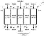
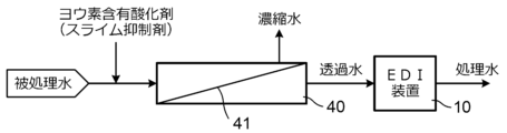
- FIG. 1 is a diagram showing an example of the configuration of an EDI device. It is a figure showing another example of composition of a water treatment device. It is a figure which shows yet another example of a structure of a water treatment apparatus.
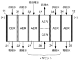
- FIG. 3 is a diagram showing another example of the configuration of an EDI device.
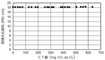
- 2 is a graph showing changes in specific resistance of treated water in Example 1.
- 3 is a graph showing changes in the water flow differential pressure in the demineralization chamber in Example 1.
- 2 is a graph showing changes in the water flow differential pressure in the concentration chamber in Example 1.
- 3 is a graph showing changes in effective iodine concentration in concentrated water in Example 3.
- FIG. 1 is a diagram showing the configuration of a water treatment apparatus according to an embodiment of the present invention.
- the water treatment device shown in FIG. 1 includes an electrodeionized water production device (EDI device) 10, and water to be treated is passed through the EDI device 10.
- the EDI device 10 performs, for example, a desalination process on the supplied water to be treated, and discharges the treated water.
- the water treatment device is equipped with a mechanism for adding an iodine-containing oxidizing agent as a slime inhibitor to the water to be treated that is supplied to the EDI device 10. Details of the iodine-containing oxidizing agent used as the slime inhibitor will be described later.
- FIG. 2 shows an example of the configuration of the EDI device 10.
- the EDI device 10 includes a demineralization chamber 23 between an anode chamber 21 having an anode 11 and a cathode chamber 25 having a cathode 12.
- a concentration chamber 22 is arranged, and a concentration chamber 24 is arranged on the side of the demineralization chamber 23 facing the cathode chamber 25.
- the anode chamber 21 and the concentration chamber 22 are partitioned by a cation exchange membrane 31, and the concentration chamber 22 and the demineralization chamber 23 are partitioned by an anion exchange membrane 32.
- a cation exchange membrane 33 partitions between the demineralization chamber 23 and the concentration chamber 24, and an anion exchange membrane 34 partitions between the concentration chamber 24 and the cathode chamber 25.
- the demineralization chamber 23 is partitioned by the anion exchange membrane 32 located on the anode 11 side and the cation exchange membrane 33 located on the cathode 12 side.
- the desalination chamber 23 is filled with ion exchange resin.
- anion exchange resin (AER) and cation exchange resin (CER) are packed in mixed bed form (MB).
- the anode chamber 21 is filled with a cation exchange resin
- the concentration chambers 22 and 24 and the cathode chamber 25 are filled with an anion exchange resin.
- the concentration chambers 22 and 24 may be filled with an anion exchange resin (AER) and a cation exchange resin (CER) in a mixed bed form.
- the dissociation reaction of water shown in equation (1) occurs due to the potential difference generated at the interface of different types of ion exchange materials due to the applied current, and hydrogen ions (H + ) and hydroxide ions (OH - ) is generated.
- the ionic components previously adsorbed on the ion exchange resin in the demineralization chamber 23 are ion-exchanged and desorbed from the ion exchange resin.
- anions move through the anion exchange membrane 32 to the concentration chamber 22 closer to the anode 11, and are discharged from this concentration chamber 22 as concentrated water.
- cations are transferred to the concentration chamber 24 closer to the cathode 12 via the cation exchange membrane 33, and are discharged from this concentration chamber 24 as concentrated water.
- the ion components in the water to be treated supplied to the demineralization chamber 23 are transferred to the concentration chambers 22 and 24 and discharged, and at the same time, the ion exchange resin in the demineralization chamber 23 is also regenerated.
- the demineralization chamber 23 discharges treated water from which ionic components have been removed, that is, deionized water. Electrode water is discharged from the anode chamber 21 and the cathode chamber 25, respectively.
- the direct current may be applied continuously when the water to be treated is flowing, or may be applied intermittently.
- At least a part of the ion exchanger filled in the desalination chamber 23 should be replaced with an anion exchanger. Therefore, it is preferable that at least a part of the ion exchanger filled in the concentration chamber 24 be an anion exchanger.
- the EDI apparatus 10 shown in FIG. 2 consists of [concentration chamber (C) 22
- the basic configuration is arranged between an anode 11 and a cathode 12.
- This basic configuration is called a cell set.
- a plurality of such cell sets are arranged in parallel between the electrodes, and the plurality of cell sets are electrically connected in series, and the anode 11 is arranged at one end of the series connection, and the cathode 12 is arranged at the other end. By doing so, processing capacity can be increased.
- the configuration of the EDI device 10 is as follows, where the repeating unit consisting of [AEM
- the configuration can be [anode chamber
- the demineralization chamber 23 closest to the anode chamber 21 the anode chamber 21 itself can function as the concentration chamber 22 without interposing an independent concentration chamber 22 between it and the anode chamber 21.
- the demineralization chamber 23 closest to the cathode chamber 25 the cathode chamber 25 itself can function as the concentration chamber 24 without interposing an independent concentration chamber 24 between it and the cathode chamber 25.
- the EDI device 10 generally has a configuration in which water to be treated passes through a space filled with an ion exchanger such as a granular ion exchange resin at a high flow rate. Slime may appear.
- an EDI device when slime is generated, blockage tends to occur, which tends to increase the water flow differential pressure and cause performance to deteriorate due to unbalanced water flow.
- an oxidizing bactericide as a slime inhibitor (ie, slime control agent).
- oxidizing disinfectants are nothing but oxidizing agents, and oxidizing agents generally deteriorate the ion exchange resin and ion exchange membrane that constitute the EDI device. For this reason, it has conventionally been considered necessary to avoid supplying water containing an oxidizing agent to an EDI device, especially an EDI device that is operating by applying a direct current.
- the present inventors investigated measures to simultaneously suppress slime generation in EDI equipment and suppress deterioration of ion exchange resins and ion exchange membranes in EDI equipment, and found that an iodine-containing oxidizing agent was used as a slime inhibitor.
- the inventors have discovered that the deterioration of performance in the EDI device can be suppressed by doing so, and have completed the present invention.
- hypochlorous acid or hypochlorite which is commonly used as a slime inhibitor, added to the water to be treated, The quality of the treated water being discharged deteriorated early.
- the iodine-containing oxidizing agent refers to an oxidizing agent containing iodine as an element, and may be an iodine compound that itself functions as an oxidizing agent, or a reaction product of an iodine compound and an oxidizing agent. It's okay. Since elemental iodine (ie, I 2 ) also has oxidizing power, solutions containing elemental iodine are also included in the category of iodine-containing oxidizing agents.
- Iodine contained as an element in the iodine-containing oxide may be in any form, such as molecular iodine, iodide, polyiodide, iodic acid, hypoiodic acid, hydrogen iodide, polyvinylpyrrolidone, etc. It may be any one of iodine coordinated to an organic solvent such as cyclodextrin, or a combination of these forms may be used. Methods for obtaining iodine in any of these forms include dissolving iodine in a nonpolar solvent such as benzene or carbon tetrachloride or alcohol, or dissolving iodine in an alkaline agent and water.
- a nonpolar solvent such as benzene or carbon tetrachloride or alcohol
- Total iodine may be obtained by adding an acid or an oxidizing agent to a solution containing at least one of iodide and iodide ions.
- polyvinylpyrrolidone can be produced using povidone-iodine, which is made by coordinating iodine with polyvinylpyrrolidone, iodine-clathrated cyclodextrin, which is made by including iodine in cyclodextrin, and iodophor, which is made by carrying iodine in organic polymers and surfactants. Iodine coordinated to an organic solvent such as cyclodextrin or cyclodextrin may also be obtained.
- iodine-containing oxidizing agent As an iodine-containing oxidizing agent, from the viewpoints of ease of handling and small impact on the quality of water to be treated and treated water, iodine alone is dissolved using iodide and water without using organic substances. A solution containing water, iodine and iodide is preferred. Iodine alone has low solubility in water, but it becomes soluble in water when iodide or iodide ions coexist. When simple iodine is dissolved using iodide and water, a stable one-component oxidizing agent with a relatively high iodine concentration can be obtained and is easy to handle.
- iodide refers to an iodine compound having an oxidation number of -1.
- examples of iodides include potassium iodide, sodium iodide, lithium iodide, hydrogen iodide, silver iodide, copper iodide, and zinc iodide. These iodides dissolve in water and dissociate to give iodide ions.
- examples of the iodine compound include potassium iodide, sodium iodide, lithium iodide, hydrogen iodide, silver iodide, and copper iodide. , zinc iodide, etc. may be used, and two or more of these may be used simultaneously.
- the iodine compound in this case from the viewpoint of cost etc., it is preferable to use sodium iodide or potassium iodide.
- oxidizing agent to be reacted with the iodine compound it is preferable to use an oxidizing agent having a higher redox potential (ORP) than iodine.
- ORP redox potential
- examples of oxidizing agents that can be used include combined chlorine and stabilized hypobromite compositions, but from the viewpoint of reaction speed, it is preferable to use an oxidizing agent that is detected as free chlorine. .
- Typical oxidizing agents detected as free chlorine include hypochlorous acid, hypobromous acid, and salts thereof.
- a stabilized hypobromite composition is a reaction product of a brominated oxidizing agent and a sulfamic acid compound, or a composition obtained by further reacting a sulfamic acid compound with a reaction product of a brominated oxidizing agent and a chlorinated oxidizing agent. It is a product produced by Examples of the bromine-based oxidizing agent herein include simple bromine, bromine chloride, bromate acid, and bromate salts.
- the molar ratio of iodide to iodine is preferably 1 or more from the viewpoint of the solubility of iodine in water, and from the viewpoint of stability.
- the pH of the solution is preferably 3 or more and 9 or less, more preferably 3 or more and 7 or less, and even more preferably 4 or more and 6.5 or less. If the pH is less than 3, iodine crystals may precipitate, and if it exceeds 9, the active ingredient may be significantly reduced.
- the active ingredient is highly concentrated and stable, so the total iodine concentration in the iodine-containing oxidizing agent is preferably 3% by mass or more, and 3% by mass.
- the content is more preferably in the range of 40% by mass or less, and even more preferably 10% by mass or more and 25% by mass or less.
- the total iodine concentration here refers to the concentration calculated based on the total chlorine concentration, regardless of whether it is iodide or simple iodine.
- the iodine-containing oxidizing agent described above is used as a slime suppressant for the EDI device 10, and is used in each chamber of the EDI device 10 (anode chamber 21, concentration chambers 22, 24, demineralization chamber 23, and cathode chamber 25). ) can also be used for cleaning. When cleaning the EDI device 10, it is sufficient to dissolve an iodine-containing oxidizing agent in pure water to obtain a cleaning solution while the operation of the EDI device 10 is stopped, and to pass this cleaning solution into each chamber of the EDI device 10. .
- iodine-containing oxidizing agent When controlling the concentration of an iodine-containing oxidizing agent in treated water, various methods for quantifying iodine can be used.
- the iodine-containing oxidizing agent is a solution containing water, iodine, and iodide
- iodine that is not an iodide is effective as an oxidizing agent.
- total chlorine or total residual chlorine
- the concentration of iodine which is effective as an oxidizing agent, can be managed using the measured value by performing measurement using a total chlorine concentration meter based on the DPD method on the premise that no residual chlorine exists.
- the iodine concentration can also be effectively managed by using a residual chlorine quantitative method or a total chlorine quantitative method other than the DPD method.
- a method for quantifying residual chlorine a method is known in which iodine liberated by residual chlorine oxidizing potassium iodide is determined by redox titration using sodium thiosulfate.
- the effective iodine concentration in the water to be treated can be determined as a value converted to the total chlorine concentration.
- effective iodine concentration instead of total iodine concentration, it may be expressed as a total chlorine concentration conversion value.
- the total chlorine concentration conversion value is the measured value obtained as the total chlorine concentration when measuring the effective iodine concentration using the method used to measure the total chlorine concentration. This is a value converted to concentration.
- the effective iodine concentration is expressed in terms of total chlorine concentration, "as Cl 2 " is added to clearly indicate this.
- the concentration of the iodine-containing oxidizing agent when added to the water to be treated needs to be such that it has sufficient bactericidal ability.
- the effective iodine concentration as an oxidizing agent in the treated water supplied to the EDI device 10 should be 0.05 mg/L as Cl 2 or more. It is preferable to do so. Even if the iodine-containing oxidizing agent has a minor effect on the EDI device compared to hypochlorous acid or the like, if the concentration of the iodine-containing oxidizing agent is excessively high, it may cause deterioration of the EDI device. Therefore, the effective iodine concentration in the water to be treated that is supplied to the EDI device 10 is preferably less than 10.0 mg/L as Cl 2 .
- the addition of the iodine-containing oxidizing agent to the water to be treated may be carried out continuously or intermittently. In order to suppress the generation of slime, it is better to add a large amount of iodine-containing oxidizing agent, but it is not necessary to continue adding iodine-containing oxidizing agent to the water to be treated; can be done intermittently. By adding the iodine-containing oxidizing agent intermittently, deterioration of the EDI device 10 can be further suppressed.
- the desalination treatment of the water to be treated is carried out continuously, and the period in which iodine-containing oxide is added to the water to be treated is defined as the addition period, and the period in which it is not added is defined as the non-addition period.
- the iodine-containing oxidizing agent can be added to the water to be treated with the addition period being in the range of 10 seconds to 12 hours and the non-addition period being in the range of 5 seconds to 320 hours so that the period is within 12 hours.
- the influence of the iodine-containing oxidizing agent on the EDI device 10 cannot be determined by the concentration of the oxidizing agent in the water to be treated while the oxidizing agent is being added. It is not appropriate to evaluate Therefore, when adding an iodine-containing oxidizing agent to the water to be treated, the effective iodine concentration as an oxidizing agent in the water to be treated is converted to the total chlorine concentration, and C is the value. It is preferable to calculate the cumulative amount of concentration C, that is, the CT value, during the period T during which the agent is added, and use the CT value as a management index.
- the water to be treated to which the iodine-containing oxidizing agent has been added is passed through the desalination chamber 23 of the EDI device 10, but the water to be treated to which the iodine-containing oxidizing agent has been added is further passed to the concentration chamber. 22, 24 and the electrode chamber.
- the anode chamber 21 and the cathode chamber 25 are collectively referred to as an electrode chamber.
- the concentration chambers 22, 24 tend to have a high ion concentration, which makes it easy for live bacteria to grow and slime to occur.
- the oxidizing agent used as a slime suppressant in the EDI device is an iodine-containing oxidizing agent rather than a chlorine-based oxidizing agent such as hypochlorous acid or hypochlorite, thereby removing the oxidizing agent. It is possible to obtain a sufficient sterilization effect while preventing deterioration of the EDI device while continuously operating the EDI device without installing a means in front of the EDI device or controlling the stoppage of the EDI device. The occurrence can be suppressed.
- FIG. 3 shows a water treatment device shown in FIG. 1 in which a reverse osmosis membrane device 40 including a reverse osmosis membrane 41 serving as a separation membrane is provided upstream of the EDI device 10.
- the water to be treated is first supplied to the reverse osmosis membrane apparatus 40.
- Permeated water that has passed through the reverse osmosis membrane 41 of the reverse osmosis membrane device 40 is supplied to the desalination chamber 23 of the EDI device 10 as water to be treated in the EDI device 10.
- the permeated water from the reverse osmosis membrane device 40 may be supplied to the concentration chambers 22 and 24 or the electrode chamber of the EDI device 10.
- the water to be treated that has not passed through the reverse osmosis membrane 41 is discharged from the reverse osmosis membrane device 40 as concentrated water.
- a mechanism for adding an iodine-containing oxidizing agent, which is a slime suppressant, to the water to be treated is provided upstream of the reverse osmosis membrane device 40.
- the impurity concentration in the water to be treated that passes through the reverse osmosis membrane device 40 and is supplied to the EDI device 10 is lower than that of the EDI in the water treatment device shown in FIG.
- the impurity concentration is lower than the impurity concentration in the water to be treated that is supplied to the apparatus 10. Therefore, in the water treatment apparatus shown in FIG. 3, slime is less likely to occur in the EDI apparatus 10 than in the water treatment apparatus shown in FIG.
- the concentration of iodine, which is effective as an oxidizing agent, in the water to be treated at the inlet of the EDI device 10 should be lower than the concentration in the water treatment device shown in FIG. is possible.
- examples of separation membranes provided upstream of the EDI device 10 include nanofiltration membranes (NF membranes), ultrafiltration membranes (UF membranes), and precision filtration membranes. (MF membrane), forward osmosis membrane (FO membrane), etc. can be used, and these membranes can also be combined.
- the water to be treated that has passed through the separation membrane is supplied to the EDI device 10.
- an iodine-containing oxidizing agent it is preferable to add to the water to be treated before the separation membrane.
- FIG. 4 shows the configuration of another water treatment device based on the present invention.
- the water treatment apparatus shown in FIG. 4 is the water treatment apparatus shown in FIG. A pipe that returns to the stage before the reverse osmosis membrane device 40 is provided.
- the total chlorine concentration meter 50 is provided to determine the concentration of the iodine-containing oxidizing agent in the permeated water of the reverse osmosis membrane device 40, specifically, the effective iodine concentration.
- the effective iodine concentration is measured as a residual chlorine concentration using a total chlorine concentration meter 50.
- Control is performed such that the value is less than a predetermined value.
- the amount of iodine-containing oxidizing agent added may be controlled based on the measured value of the total chlorine concentration meter 50, or the amount of permeated water discharged from the reverse osmosis membrane device 40 may be reduced.
- the amount of water returned to the front stage of the reverse osmosis membrane device 40 can be increased or decreased, or an activated carbon device can be installed at the permeated water outlet of the reverse osmosis membrane device 40. What is necessary is to adjust the oxidizing agent concentration in the treated water.
- the water treatment equipment shown in FIGS. 3 and 4 has a reverse osmosis membrane device 40 placed before the EDI device 10, and an oxidizing agent containing iodine is added to the water to be treated that is supplied to the reverse osmosis membrane device 40. This is what I did. Also in these water treatment devices, the addition of the iodine-containing oxidizing agent to the water to be treated may be carried out continuously or intermittently.
- an iodine-containing oxidizing agent is added to the treated water at a stage before the reverse osmosis membrane device 40. Even when the iodine-containing oxidizing agent is added to the oxidizing agent, it is preferable to add the iodine-containing oxidizing agent intermittently.
- the addition period is within a range of 10 seconds to 12 hours so that the addition period is within 12 hours within any 24 hours
- the iodine-containing oxidizing agent can be added to the water to be treated that is supplied to the reverse osmosis membrane device 40 while the non-addition period is in the range of 5 seconds to 320 hours.
- FIG. 5 shows another example of an EDI device that can be used in each of the water treatment devices shown in FIGS. 1, 3, and 4.
- the demineralization chamber 23 of the EDI device 10 shown in FIG. A second small demineralization chamber 28 is located closer to the cathode 12 than the ion exchange membrane.
- An anion exchange membrane 37 is used as the intermediate ion exchange membrane. Therefore, the first small demineralization chamber 27 is partitioned by the anion exchange membrane 32 and the anion exchange membrane 37, and the second small demineralization chamber 28 is partitioned by the anion exchange membrane 37 and the cation exchange membrane 33.
- the water to be treated is first supplied to the first small demineralization chamber 27, the outlet water of the first small demineralization chamber 27 is directly supplied to the second small demineralization chamber 28, and the water to be treated is supplied to the second small demineralization chamber 28.
- the treated water of this EDI device is discharged from 28.
- the first small demineralization chamber 27 is filled with anion exchange resin.
- the second small demineralization chamber 28 has a double-bed configuration, and the upstream side is filled with a cation exchange resin and the downstream side is filled with an anion exchange resin along the flow direction of the water to be treated. .
- the arrangement consisting of the anion exchange membrane 32, the first small demineralization chamber 27, the anion exchange membrane 37, the second small demineralization chamber 28, the cation exchange membrane 33, and the concentration chamber 24 is repeated as a unit X.
- a plurality of sets of repeating units X can be provided in series between the concentration chamber 22 adjacent to the anode chamber 21 and the anion exchange membrane 34 in contact with the cathode chamber 25.
- the iodine-containing oxidizing agent used in this embodiment is an oxidizing agent that contains iodine as an element, and by adding the iodine-containing oxidizing agent, the water to be treated has oxidizing power. Become. Therefore, if the water to be treated already contains an oxidizing agent and has oxidizing power, simply adding iodide to the water will make the water to be treated the same as when an iodine-containing oxidizing agent is added. be in the same state. Similarly, if the treated water itself already contains iodide, simply adding an oxidizing agent to the treated water will leave the treated water in the same state as it was when the iodine-containing oxidizing agent was added. Become.
- the present invention applies not only when a chemical is added to the water to be treated and the chemical is an oxidizing agent containing iodine, but also when the water to be treated already contains an oxidizing agent.
- the scope of the present invention also includes cases where an iodine-containing chemical and an oxidizing agent are separately added to the water to be treated so that the oxidizing agent containing iodine is produced by mixing or reaction in the water to be treated.
- the effective iodine concentration is a value obtained by measuring the total chlorine concentration using the DPD method.
- the CT value is a value obtained as the cumulative amount of the effective iodine concentration C in the water to be treated during the period T during which the iodine-containing oxidizing agent is added.
- Example 1 The EDI apparatus 10 shown in FIG. 5 is assembled, and the EDI apparatus 10 is operated by supplying treated water to which an iodine-containing oxidizing agent has been added as a slime inhibitor.
- the changes in differential pressure were investigated.
- the water flow differential pressure across the first small demineralization chamber 27 and the second small demineralization chamber 28 is defined as the water flow differential pressure of the demineralization chamber.
- the water to be treated was well water in Sagamihara City treated with a reverse osmosis membrane device, and the effective iodine concentration in the water to be treated was 0.75 mg/L as Cl 2 when an oxidizing agent containing iodine was added. did.
- a solution containing water, iodine, and iodide was used as the iodine-containing oxide.
- the results regarding the specific resistance of the treated water are shown in FIG. 6, the results regarding the water flow differential pressure in the demineralization chamber are shown in FIG. 7, and the results regarding the water flow differential pressure in the concentration chamber are shown in FIG. 8.
- the horizontal axis in these figures is represented by CT values.
- Example 1 when an iodine-containing oxidizing agent is used as a slime inhibitor, the specific resistance of the treated water of the EDI device is maintained high over a long period of time, and the water flow differential pressure between the desalination chamber and the concentration chamber is almost unchanged. It didn't change.
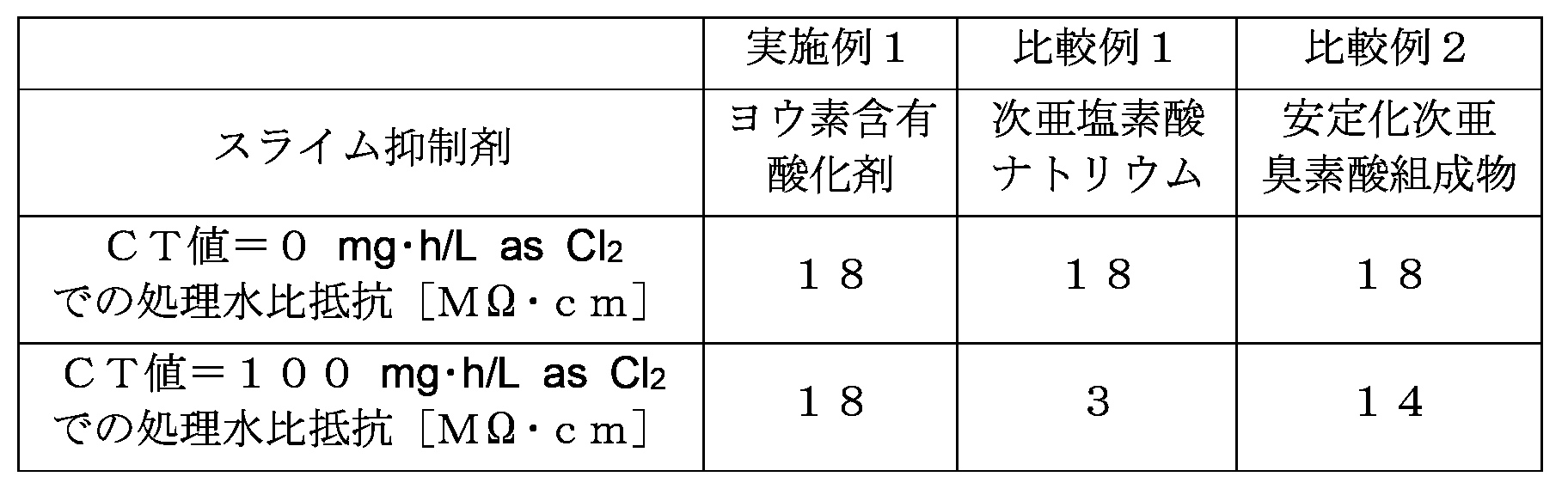
- Comparative Example 1 using sodium hypochlorite as a slime inhibitor and Comparative Example 2 using a stabilized hypobromite composition the specific resistance decreased as the operating time of the EDI device increased, The quality of treated water deteriorated.
- Example 2 Comparative Examples 3 and 4
- a slime inhibitor was brought into contact with water containing viable bacteria, and the number of viable bacteria before contact with the slime inhibitor and the number of viable bacteria after contact with the slime inhibitor for one hour were determined.
- Example 2 used the same iodine-containing oxidizing agent as used in Example 1, Comparative Example 3 used sodium hypochlorite, and Comparative Example 4 used stabilized hypobromite.
- the composition was used.
- the concentration of slime inhibitor was 0.1 mg/L as Cl 2 in each case. The results are shown in Table 2.
- the iodine-containing oxidizing agent has stronger bactericidal activity as a slime inhibitor than sodium hypochlorite or stabilized hypobromite compositions.
- an iodine-containing oxidizing agent as a slime suppressant, it is possible to suppress the deterioration of the quality of treated water in the EDI device and the increase in water flow differential pressure, so the iodine-containing oxidizing agent can also be used in the EDI device during operation. It was found to be an excellent slime suppressant.
- Example 3 The EDI apparatus 10 shown in FIG. 5 is assembled, and the water to be treated to which an iodine-containing oxidizing agent is added as a slime inhibitor is supplied to the first small desalination chamber 27, concentration chambers 22, 24, and electrode chamber of the EDI apparatus 10, and the EDI Apparatus 10 was operated. Then, the ratio of the cumulative amount of effective iodine continuously flowing into the EDI device 10 to the total volume of the anion exchange resin (AER) filled in the concentration chambers 22 and 24 of the EDI device 10, and the ratio of the cumulative amount of effective iodine discharged from the EDI device 10. The relationship between the effective iodine concentration and the concentration of concentrated water was investigated.
- AER anion exchange resin
- the results are shown in FIG. Until the cumulative amount of available iodine continuously flowing into the EDI device 10 reaches a certain value, no leakage of iodine components into the concentrated water flowing out from the concentration chambers 22 and 24 occurs, and iodine is transferred to the anion exchange resin in the EDI device 10. It was found that it was captured by The iodine component referred to here also includes iodide ions.
- Electrodeionized water production equipment EDI equipment
- Reverse osmosis membrane device 41 Reverse osmosis membrane 50
- Total chlorine concentration meter 11
- Anode 12
- Cathode 21
- Anode chamber 22
- Concentration chamber 23
- Demineralization chamber 25
- Cathode chamber 27
- Small demineralization chamber 28
- Cation exchange membrane 32, 34, 37
- Anion exchange membrane
Landscapes
- Chemical & Material Sciences (AREA)
- Engineering & Computer Science (AREA)
- Water Supply & Treatment (AREA)
- Life Sciences & Earth Sciences (AREA)
- Chemical Kinetics & Catalysis (AREA)
- Hydrology & Water Resources (AREA)
- Environmental & Geological Engineering (AREA)
- Organic Chemistry (AREA)
- Health & Medical Sciences (AREA)
- Analytical Chemistry (AREA)
- Molecular Biology (AREA)
- Electrochemistry (AREA)
- General Chemical & Material Sciences (AREA)
- Urology & Nephrology (AREA)
- Treatment Of Water By Oxidation Or Reduction (AREA)
- Separation Using Semi-Permeable Membranes (AREA)
- Water Treatment By Electricity Or Magnetism (AREA)
Abstract
Description
図5に示したEDI装置10を組み立て、このEDI装置10に対し、スライム抑制剤としてヨウ素含有酸化剤を添加した被処理水を供給してEDI装置10を運転し、そのときの第2小脱塩室28から排出される処理水の比抵抗と、第1小脱塩室27および第2小脱塩室28の全体での通水差圧の変化と、濃縮室22,24での通水差圧の変化とを調べた。第1小脱塩室27および第2小脱塩室28の全体での通水差圧を脱塩室の通水差圧とする。被処理水としては相模原市における井水を逆浸透膜装置によって処理したものを使用し、ヨウ素含有酸化剤を添加するときの被処理水での有効ヨウ素濃度を0.75mg/L as Cl2とした。ヨウ素含有酸化物として、水とヨウ素とヨウ化物とを含む溶液を使用した。処理水の比抵抗に関する結果を図6に示し、脱塩室の通水差圧に関する結果を図7に示し、濃縮室の通水差圧に関する結果を図8に示す。これらの図における横軸はCT値で表されている。
図5に示すEDI装置10を組み立て、実施例1と同様に運転し、処理水の比抵抗の変化を調べた。ただし、被処理水に添加されるスライム抑制剤として、比較例1では次亜塩素酸ナトリウムを使用し、比較例2では安定化次亜臭素酸組成物を使用した。表1は、運転開始前と、運転開始後にCT値が100mg・h/L as Cl2となったときに得られた処理水の比抵抗を、上述した実施例1の場合での結果とともに示している。
生菌を含む水に対してスライム抑制剤を接触させ、スライム抑制剤を接触させる前の生菌数とスライム抑制剤を1時間にわたって接触させた後の生菌数とを調べた。スライム抑制剤として、実施例2では、実施例1で用いたものと同じヨウ素含有酸化剤を使用し、比較例3では次亜塩素酸ナトリウムを使用し、比較例4では安定化次亜臭素酸組成物を使用した。スライム抑制剤の濃度はいずれの場合も0.1mg/L as Cl2であった。結果を表2に示す。

図5に示すEDI装置10を組み立て、スライム抑制剤としてヨウ素含有酸化剤を添加した被処理水をEDI装置10の第1小脱塩室27、濃縮室22,24及び電極室に供給してEDI装置10を運転した。そして、EDI装置10の濃縮室22,24に充填されているアニオン交換樹脂(AER)の体積の総量に対するEDI装置10に連続して流入した有効ヨウ素の累積量の比と、EDI装置10から排出される濃縮水における有効ヨウ素濃度との関係を調べた。その結果を図9に示す。EDI装置10に連続して流れ込む有効ヨウ素の累積量がある値に達するまでは、濃縮室22,24から流れ出る濃縮水へのヨウ素成分のリークが起こらず、ヨウ素がEDI装置10内のアニオン交換樹脂に捕捉されることが分かった。ここでいうヨウ素成分は、ヨウ化物イオンなども含んでいる。
40 逆浸透膜装置
41 逆浸透膜
50 全塩素濃度計
11 陽極
12 陰極
21 陽極室
22,24 濃縮室
23 脱塩室
25 陰極室
27,28 小脱塩室
31,33 カチオン交換膜
32,34,37 アニオン交換膜
Claims (10)
- 被処理水に薬品を添加してヨウ素を含有するとともに酸化力を有する被処理水を得る添加工程と、
前記添加工程を経た前記被処理水を電気式脱イオン水製造装置に供給して前記電気式脱イオン水製造装置において処理する処理工程と、
を有し、
前記電気式脱イオン水製造装置の脱塩室に充填されているイオン交換体の少なくとも一部がアニオン交換体である、水処理方法。 - 前記処理工程において前記添加工程を経た前記被処理水を前記電気式脱イオン水製造装置に供給する前に、前記添加工程を経た前記被処理水を分離膜で処理する、請求項1に記載の水処理方法。
- 前記薬品は、水とヨウ素とヨウ化物とを含む溶液である、請求項1または2に記載の水処理方法。
- 被処理水に薬品を添加してヨウ素を含有するとともに酸化力を有する被処理水とする添加手段と、
脱塩室に充填されるイオン交換体の少なくとも一部がアニオン交換体である電気式脱イオン水製造装置と、
を備え、
前記添加手段により前記薬品が添加された前記被処理水が前記電気式脱イオン水製造装置に供給される、水処理装置。 - 前記添加手段の後段であって前記電気式脱イオン水製造装置の前段となる位置に分離膜が設けられ、
前記薬品が添加された前記被処理水が、前記分離膜によって処理されたのちに前記電気式脱イオン水製造装置に供給される、請求項4に記載の水処理装置。 - 前記薬品は、水とヨウ素とヨウ化物とを含む溶液である、請求項4または5に記載の水処理装置。
- 前記電気式脱イオン水製造装置の濃縮室に充填されるイオン交換体の少なくとも一部がアニオン交換体である、請求項4または5に記載の水処理装置。
- ヨウ素含有酸化剤を含み、電気式脱イオン水製造装置に用いられるスライム抑制剤。
- 水とヨウ素とヨウ化物とを含む溶液である、請求項8に記載のスライム抑制剤。
- 請求項8または9に記載のスライム抑制剤を含む洗浄液を電気式脱イオン水製造装置に通液して前記電気式脱イオン水製造装置を洗浄する、洗浄方法。
Priority Applications (3)
| Application Number | Priority Date | Filing Date | Title |
|---|---|---|---|
| CN202380047340.7A CN119365421A (zh) | 2022-06-16 | 2023-04-28 | 水处理方法、水处理装置、粘泥抑制剂以及清洗方法 |
| US18/874,253 US20250346512A1 (en) | 2022-06-16 | 2023-04-28 | Water treatment method, water treatment apparatus, slime inhibitor, and cleaning method |
| KR1020247042891A KR20250016292A (ko) | 2022-06-16 | 2023-04-28 | 수처리방법, 수처리장치, 슬라임 억제제 및 세정 방법 |
Applications Claiming Priority (2)
| Application Number | Priority Date | Filing Date | Title |
|---|---|---|---|
| JP2022096973A JP2023183453A (ja) | 2022-06-16 | 2022-06-16 | 水処理方法、水処理装置、スライム抑制剤、および洗浄方法 |
| JP2022-096973 | 2022-06-16 |
Publications (1)
| Publication Number | Publication Date |
|---|---|
| WO2023243244A1 true WO2023243244A1 (ja) | 2023-12-21 |
Family
ID=89190971
Family Applications (1)
| Application Number | Title | Priority Date | Filing Date |
|---|---|---|---|
| PCT/JP2023/016864 Ceased WO2023243244A1 (ja) | 2022-06-16 | 2023-04-28 | 水処理方法、水処理装置、スライム抑制剤、および洗浄方法 |
Country Status (6)
| Country | Link |
|---|---|
| US (1) | US20250346512A1 (ja) |
| JP (1) | JP2023183453A (ja) |
| KR (1) | KR20250016292A (ja) |
| CN (1) | CN119365421A (ja) |
| TW (1) | TW202408943A (ja) |
| WO (1) | WO2023243244A1 (ja) |
Citations (4)
| Publication number | Priority date | Publication date | Assignee | Title |
|---|---|---|---|---|
| WO2021192582A1 (ja) * | 2020-03-24 | 2021-09-30 | オルガノ株式会社 | 水処理方法、水処理装置、および膜用のスライム抑制剤 |
| JP2021151966A (ja) * | 2020-03-24 | 2021-09-30 | オルガノ株式会社 | 殺菌剤、殺菌剤の製造方法、殺菌方法、分離膜用スライム抑制剤、および分離膜のスライム抑制方法 |
| JP2022046426A (ja) * | 2020-09-10 | 2022-03-23 | オルガノ株式会社 | 水処理システム、純水製造方法及び水処理方法 |
| WO2022186013A1 (ja) * | 2021-03-05 | 2022-09-09 | オルガノ株式会社 | 水処理方法および水処理剤組成物 |
Family Cites Families (10)
| Publication number | Priority date | Publication date | Assignee | Title |
|---|---|---|---|---|
| JPH0539586A (ja) * | 1991-08-05 | 1993-02-19 | Japan Carlit Co Ltd:The | 過ハロゲン酸水溶液の製造方法 |
| JP3965001B2 (ja) | 1999-03-29 | 2007-08-22 | オルガノ株式会社 | 脱イオン水製造装置 |
| JP3864891B2 (ja) * | 2002-07-01 | 2007-01-10 | 栗田工業株式会社 | 電気式脱イオン装置 |
| JP2004113973A (ja) | 2002-09-27 | 2004-04-15 | Japan Organo Co Ltd | 純水製造装置の洗浄方法 |
| JP4669584B2 (ja) * | 2009-03-30 | 2011-04-13 | 日本製紙株式会社 | N−オキシル化合物の回収・再利用方法 |
| US9790109B2 (en) * | 2010-04-30 | 2017-10-17 | General Electric Company | Method for sanitizing an electrodeionization device |
| JP5658908B2 (ja) * | 2010-05-19 | 2015-01-28 | ダイセン・メンブレン・システムズ株式会社 | 精製水の製造方法 |
| JP6401491B2 (ja) | 2013-08-28 | 2018-10-10 | オルガノ株式会社 | 分離膜のスライム抑制方法、逆浸透膜またはナノろ過膜用スライム抑制剤組成物、および分離膜用スライム抑制剤組成物の製造方法 |
| JP6730898B2 (ja) * | 2016-09-27 | 2020-07-29 | オルガノ株式会社 | 電気式脱イオン水製造装置およびその運転方法 |
| CN111961547A (zh) * | 2020-08-07 | 2020-11-20 | 开源智德科技(深圳)有限公司 | 一种高效环保无水洗车清洁液及其制备方法 |
-
2022
- 2022-06-16 JP JP2022096973A patent/JP2023183453A/ja active Pending
-
2023
- 2023-04-28 US US18/874,253 patent/US20250346512A1/en active Pending
- 2023-04-28 KR KR1020247042891A patent/KR20250016292A/ko active Pending
- 2023-04-28 WO PCT/JP2023/016864 patent/WO2023243244A1/ja not_active Ceased
- 2023-04-28 CN CN202380047340.7A patent/CN119365421A/zh active Pending
- 2023-05-25 TW TW112119469A patent/TW202408943A/zh unknown
Patent Citations (4)
| Publication number | Priority date | Publication date | Assignee | Title |
|---|---|---|---|---|
| WO2021192582A1 (ja) * | 2020-03-24 | 2021-09-30 | オルガノ株式会社 | 水処理方法、水処理装置、および膜用のスライム抑制剤 |
| JP2021151966A (ja) * | 2020-03-24 | 2021-09-30 | オルガノ株式会社 | 殺菌剤、殺菌剤の製造方法、殺菌方法、分離膜用スライム抑制剤、および分離膜のスライム抑制方法 |
| JP2022046426A (ja) * | 2020-09-10 | 2022-03-23 | オルガノ株式会社 | 水処理システム、純水製造方法及び水処理方法 |
| WO2022186013A1 (ja) * | 2021-03-05 | 2022-09-09 | オルガノ株式会社 | 水処理方法および水処理剤組成物 |
Also Published As
| Publication number | Publication date |
|---|---|
| KR20250016292A (ko) | 2025-02-03 |
| JP2023183453A (ja) | 2023-12-28 |
| TW202408943A (zh) | 2024-03-01 |
| CN119365421A (zh) | 2025-01-24 |
| US20250346512A1 (en) | 2025-11-13 |
Similar Documents
| Publication | Publication Date | Title |
|---|---|---|
| JP7731691B2 (ja) | 水処理方法及び水処理装置 | |
| JP6401491B2 (ja) | 分離膜のスライム抑制方法、逆浸透膜またはナノろ過膜用スライム抑制剤組成物、および分離膜用スライム抑制剤組成物の製造方法 | |
| JP6616855B2 (ja) | ろ過処理システムおよびろ過処理方法 | |
| US6328896B1 (en) | Process for removing strong oxidizing agents from liquids | |
| JP6534524B2 (ja) | ろ過処理システムおよびろ過処理方法 | |
| CN107108277B (zh) | 分离膜的黏质抑制方法 | |
| JP6688381B2 (ja) | 逆浸透膜を用いた水処理システムおよび水処理方法 | |
| JP6622424B2 (ja) | 逆浸透膜処理方法および逆浸透膜処理システム | |
| JP2014176799A (ja) | 逆浸透膜分離方法 | |
| JP6778591B2 (ja) | 超純水製造方法及び超純水製造システム | |
| JP6730898B2 (ja) | 電気式脱イオン水製造装置およびその運転方法 | |
| JP5998929B2 (ja) | 膜分離方法 | |
| JP2016120466A (ja) | ろ過処理システムおよびろ過処理方法 | |
| JP2018153749A (ja) | 逆浸透膜を用いる水処理方法および水処理システム | |
| JP6513424B2 (ja) | 分離膜の殺菌方法 | |
| JP6837301B2 (ja) | 逆浸透膜処理方法および逆浸透膜処理システム | |
| JP2008178845A5 (ja) | ||
| JP2008178845A (ja) | 電解次亜塩素水製造装置 | |
| WO2021192583A1 (ja) | 水回収システムおよび水回収方法 | |
| JP7065723B2 (ja) | 水処理システム及びその運転方法、並びに保護装置 | |
| WO2023243244A1 (ja) | 水処理方法、水処理装置、スライム抑制剤、および洗浄方法 | |
| JP7333865B2 (ja) | 水処理方法および水処理装置 | |
| JP2018122274A (ja) | 水処理システム及びその運転方法並びに保護装置 | |
| JP7605694B2 (ja) | 水処理方法及び水処理装置 | |
| JP7008470B2 (ja) | 逆浸透膜処理方法および逆浸透膜処理システム |
Legal Events
| Date | Code | Title | Description |
|---|---|---|---|
| 121 | Ep: the epo has been informed by wipo that ep was designated in this application |
Ref document number: 23823547 Country of ref document: EP Kind code of ref document: A1 |
|
| WWE | Wipo information: entry into national phase |
Ref document number: 18874253 Country of ref document: US |
|
| WWE | Wipo information: entry into national phase |
Ref document number: 202380047340.7 Country of ref document: CN |
|
| ENP | Entry into the national phase |
Ref document number: 20247042891 Country of ref document: KR Kind code of ref document: A |
|
| NENP | Non-entry into the national phase |
Ref country code: DE |
|
| WWP | Wipo information: published in national office |
Ref document number: 202380047340.7 Country of ref document: CN |
|
| WWP | Wipo information: published in national office |
Ref document number: 1020247042891 Country of ref document: KR |
|
| 122 | Ep: pct application non-entry in european phase |
Ref document number: 23823547 Country of ref document: EP Kind code of ref document: A1 |
|
| WWP | Wipo information: published in national office |
Ref document number: 18874253 Country of ref document: US |