WO2023238229A1 - 電力変換装置、モータ駆動装置及び冷凍サイクル適用機器 - Google Patents
電力変換装置、モータ駆動装置及び冷凍サイクル適用機器 Download PDFInfo
- Publication number
- WO2023238229A1 WO2023238229A1 PCT/JP2022/022941 JP2022022941W WO2023238229A1 WO 2023238229 A1 WO2023238229 A1 WO 2023238229A1 JP 2022022941 W JP2022022941 W JP 2022022941W WO 2023238229 A1 WO2023238229 A1 WO 2023238229A1
- Authority
- WO
- WIPO (PCT)
- Prior art keywords
- power
- capacitor
- conversion device
- inverter
- current
- Prior art date
- Legal status (The legal status is an assumption and is not a legal conclusion. Google has not performed a legal analysis and makes no representation as to the accuracy of the status listed.)
- Ceased
Links
Images






Classifications
-
- H—ELECTRICITY
- H02—GENERATION; CONVERSION OR DISTRIBUTION OF ELECTRIC POWER
- H02M—APPARATUS FOR CONVERSION BETWEEN AC AND AC, BETWEEN AC AND DC, OR BETWEEN DC AND DC, AND FOR USE WITH MAINS OR SIMILAR POWER SUPPLY SYSTEMS; CONVERSION OF DC OR AC INPUT POWER INTO SURGE OUTPUT POWER; CONTROL OR REGULATION THEREOF
- H02M7/00—Conversion of AC power input into DC power output; Conversion of DC power input into AC power output
- H02M7/42—Conversion of DC power input into AC power output without possibility of reversal
- H02M7/44—Conversion of DC power input into AC power output without possibility of reversal by static converters
- H02M7/48—Conversion of DC power input into AC power output without possibility of reversal by static converters using discharge tubes with control electrode or semiconductor devices with control electrode
Definitions
- the present disclosure relates to a power conversion device that converts AC power supplied from an AC power source into AC power with a voltage different from the AC power and supplies it to a load, and a motor drive device and refrigeration cycle application equipment equipped with the same.
- a power conversion device that converts AC power supplied from an AC power source into AC power with a different voltage from this AC power, and supplies it to a load such as an air conditioner.
- a power converter rectifies AC power supplied from an AC power source using a diode bridge circuit, smoothes it using a smoothing capacitor, converts the smoothed power into desired AC power using an inverter made up of multiple switching elements, and converts it into a load. Output to compressor motor.
- an inrush current flows to rapidly charge the smoothing capacitor when the power is turned on. If an inrush current flows through a semiconductor component such as a diode bridge, it may exceed the withstand capacity of the component and cause it to be destroyed, so it is necessary to suppress the inrush current by using an inrush current prevention circuit.
- Patent Document 1 discloses that the device has a means for detecting the voltage of an AC power source, and when the amount of electricity determined from the voltage detected by the voltage detection means becomes equal to or less than a first set value, a torque is generated according to the reduced amount of electricity.
- a power converter that reduces the command value of the current component at a preset rate, and reduces the command value of the torque current component to zero when the amount of electricity becomes equal to or less than a second set value that is smaller than the first set value. is disclosed.
- the power conversion device disclosed in Patent Document 1 can quickly return to a normal state after power is restored from an instantaneous power outage.
- Patent Document 1 since the power conversion device disclosed in Patent Document 1 reduces the torque current only when an instantaneous power outage is detected, a large current flows through the smoothing capacitor during normal operation, which accelerates aging deterioration of the smoothing capacitor. There was a problem. In addition, it is possible to suppress ripple changes in the capacitor voltage by increasing the capacitance of the smoothing capacitor, or to use a smoothing capacitor that has a high resistance to deterioration due to ripples, but this poses the problem of increasing the size of the device.
- the present disclosure has been made in view of the above, and aims to provide a power conversion device that suppresses aging deterioration of a smoothing capacitor without increasing the size of the device.
- a power conversion device includes an inrush current prevention section that prevents inrush current, an instantaneous power outage detection section that detects an instantaneous power outage of the commercial power supply, and a power conversion device that prevents an inrush current.
- a rectifier that rectifies the first AC power supplied from the rectifier; a capacitor connected to the output end of the rectifier; and an inverter that converts it into a load and outputs it to the load.
- the power converter controls the operation of the inverter so that the inverter outputs second AC power including pulsations corresponding to the pulsations of power flowing into the capacitor from the rectifier to the load, and controls the current flowing to the capacitor. It is equipped with a section and a section.
- the power conversion device has the effect of suppressing aging deterioration of the smoothing capacitor without increasing the size of the device.
- a diagram showing the configuration of a power conversion device according to Embodiment 1 A diagram showing the current flowing from the rectifying section, the current flowing to the inverter, the current flowing from the smoothing section, and the capacitor voltage of the power conversion device according to Embodiment 1.
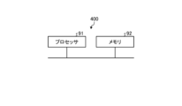
- Flowchart showing the operation of the control unit included in the power conversion device according to Embodiment 1 A diagram illustrating an example of a hardware configuration that implements a control unit included in the power conversion device according to Embodiment 1.
- a diagram showing the configuration of a power conversion device according to Embodiment 2 Flowchart showing the operation of the control unit included in the power conversion device according to Embodiment 2
- a diagram showing the configuration of a power conversion device according to a modification of Embodiment 2 A diagram showing the configuration of a refrigeration cycle application device according to Embodiment 3
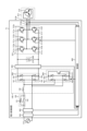
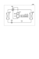
- FIG. 1 is a diagram showing the configuration of a power conversion device according to Embodiment 1.
- Power conversion device 1a is connected to commercial power source 110 and compressor 315.
- the power conversion device 1a converts the first AC power of the power supply voltage Vs supplied from the commercial power supply 110 into second AC power having an amplitude and phase different from the first AC power, and supplies the second AC power to the compressor 315. .
- the power conversion device 1a includes an inrush current prevention section 120, an instantaneous power failure detection section 502, a voltage/current detection section 501, a reactor 130, a rectification section 140, a voltage detection section 503, a smoothing section 200, an inverter 310, , current detection sections 313a and 313b, and a control section 400.
- the power conversion device 1a and the motor 314 included in the compressor 315 constitute a motor drive device 2a.
- the inrush current prevention unit 120 includes an inrush current prevention element 121 connected in series to the commercial power supply 110 and a switching element 122 connected in parallel to the inrush current prevention element 121.
- the inrush current prevention element 121 suppresses inrush current that occurs when the commercial power source 110 is turned on to the power conversion device 1a.
- Examples of the inrush current prevention element 121 include, but are not limited to, a PTC (Positive Temperature Coefficient) thermistor, a cement resistor, and a thermal fuse resistor.
- the switching element 122 short-circuits the inrush current prevention element 121 by turning on the switching element 122 during normal operation, thereby suppressing the loss that regularly occurs in the inrush current prevention element 121.
- the switching element 122 examples include, but are not limited to, a relay, a thyristor, and a triac.
- the inrush current prevention element 121 may be connected to the path from the commercial power source 110 to the smoothing section 200.
- the inrush current prevention element 121 may be connected closer to the commercial power supply 110 than the rectifier 140, or may be connected closer to the motor 314 than the rectifier 140.
- the rush current prevention element 121 may be connected to the positive electrode side or may be connected to the negative electrode side.
- the instantaneous power failure detection unit 502 detects the voltage of the commercial power supply 110 and outputs the detected value to the control unit 400.
- the voltage and current detection unit 501 detects the voltage and current values of the first AC power of the power supply voltage Vs supplied from the commercial power supply 110 and outputs the detected voltage and current values to the control unit 400.
- the reactor 130 is connected between the rush current prevention section 120 and the rectification section 140.
- the rectifier 140 includes a rectifier circuit 500 and rectifies the first AC power of the power supply voltage Vs supplied from the commercial power supply 110 and outputs the rectifier.
- the rectifier circuit 500 is a bridge circuit configured by rectifying elements 141, 142, 143, and 144.
- the rectifier 140 performs full-wave rectification.
- Voltage detection section 503 detects the voltage value of the power rectified by rectification section 140 and outputs the detected voltage value to control section 400.
- Smoothing section 200 is connected to the output end of rectifying section 140 via voltage detecting section 503 .
- the smoothing section 200 has a capacitor 210 as a smoothing element, and smoothes the power rectified by the rectifying section 140. Examples of the capacitor 210 include an electrolytic capacitor and a film capacitor, but are not limited thereto. Capacitor 210 has a capacity to smooth the power rectified by rectifier 140.
- the voltage generated in the capacitor 210 due to smoothing does not have a full-wave rectified waveform of the commercial power supply 110, but has a waveform in which a voltage ripple corresponding to the frequency of the commercial power supply 110 is superimposed on a DC component, and does not pulsate significantly.
- the main component of the frequency of this voltage ripple is a component twice the frequency of the power supply voltage Vs when the commercial power supply 110 is single-phase, and a component six times the frequency of the power supply voltage Vs when the commercial power supply 110 is three-phase.
- the amplitude of this voltage ripple is determined by the capacitance of capacitor 210. For example, the voltage ripple generated in capacitor 210 pulsates within a range where the maximum value is less than twice the minimum value.
- the inverter 310 is connected to the smoothing section 200. That is, inverter 310 is connected to both ends of capacitor 210.
- the inverter 310 has switching elements 311a, 311b, 311c, 311d, 311e, 311f and free wheel diodes 312a, 312b, 312c, 312d, 312e, 312f.
- the inverter 310 turns on and off the switching elements 311a, 311b, 311c, 311d, 311e, and 311f under the control of the control unit 400, and converts the power output from the rectifying unit 140 and the smoothing unit 200 to an amplitude different from the first AC power. It is converted into second AC power having a phase and output to the compressor 315.
- the control unit 400 acquires the voltage value and current value of the first AC power of the power supply voltage Vs from the voltage/current detection unit 501. Further, the control unit 400 acquires the voltage value of the power rectified by the rectification unit 140 from the voltage detection unit 503. Further, the control unit 400 acquires the current value of the second AC power having a different amplitude and phase from the first AC power converted by the inverter 310 from the current detection units 313a and 313b. The control unit 400 uses the detection values detected by each detection unit to control the operation of the inverter 310, specifically, the on/off of switching elements 311a, 311b, 311c, 311d, 311e, and 311f included in the inverter 310. .
- Current I3 can be expressed as the difference between current I2 and current I1, ie, current I2-I1.
- the current I3 has a positive direction in the discharging direction of the smoothing section 200 and a negative direction in the charging direction of the smoothing section 200. That is, a current may flow into the smoothing portion 200, and a current may flow out of the smoothing portion 200.
- the control section 400 controls the current I2 flowing through the inverter 310 so as to reduce the current I3 flowing through the smoothing section 200. That is, the control section 400 controls the operation of the inverter 310 so as to reduce the current I3 flowing through the smoothing section 200.
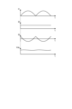
- the control unit 400 of the power conversion device 1a controls the operation of the inverter 310 so that the current I2 as shown in FIG.
- the frequency component of the current flowing into the smoothing section 200 can be reduced, and the current I3 flowing into the smoothing section 200 can be reduced.
- the control unit 400 controls the operation of the inverter 310 so that a current I2 including a pulsating current whose main component is the frequency component of the current I1 flows through the inverter 310.
- the frequency component of the current I1 is determined by the frequency of the alternating current supplied from the commercial power supply 110 and the configuration of the rectifier 140. Therefore, the control unit 400 can set the frequency component of the pulsating current superimposed on the current I2 to a component having a predetermined amplitude and phase.
- the frequency component of the pulsating current superimposed on the current I2 has a similar waveform to the frequency component of the current I1.
- the control unit 400 reduces the current I3 flowing through the smoothing unit 200 as the frequency component of the pulsating current superimposed on the current I2 approaches the frequency component of the current I1, thereby reducing the pulsating voltage generated in the capacitor voltage Vdc. I can do it.
- Controlling the pulsation of the current flowing through the inverter 310 by the control unit 400 controlling the operation of the inverter 310 is the same as controlling the pulsation of the first AC power output from the inverter 310 to the compressor 315. be.
- Control unit 400 controls the operation of inverter 310 so that the pulsations included in the second AC power output from inverter 310 are smaller than the pulsations in the power output from rectifier 140.
- the control unit 400 controls the voltage ripple of the capacitor voltage Vdc, that is, the voltage ripple generated in the capacitor 210, so that the second AC power output from the inverter 310 does not include pulsations corresponding to the pulsations of the power flowing into the capacitor 210.
- the amplitude and phase of the pulsation contained in the second AC power output from the inverter 310 is controlled so that the voltage ripple that occurs in the capacitor 210 is smaller than the voltage ripple that occurs in the capacitor 210 at that time.
- the control unit 400 controls the current ripple flowing in and out of the capacitor 210 when the second AC power output from the inverter 310 does not include pulsations corresponding to the pulsations of the power flowing into the capacitor 210.
- the amplitude and phase of pulsation contained in the second AC power output from inverter 310 is controlled so that it is smaller than the generated current ripple.
- control unit 400 may set the pulsating waveform of the current I2 to a rectangular wave shape or a triangular wave shape. In this case, the control unit 400 may set the amplitude and phase of the pulsating waveform to predefined values.
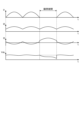
- FIG. 4 is a diagram showing the current flowing from the rectifying section, the current flowing to the inverter, the current flowing from the smoothing section, and the capacitor voltage of the power conversion device according to the first embodiment.
- each current is shown when the control unit 400 does not limit the current I2 flowing through the inverter 310 when a momentary power failure occurs, but makes the current I2 before the momentary power failure equal to the current I2 during the momentary power failure period.
- An example of I1, I2, I3 and the capacitor voltage Vdc of the smoothing section 200 is shown.
- current I1, current I2, current I3, and capacitor voltage Vdc are shown in order from the top. Note that the capacitor voltage Vdc is generated according to the current I3.
- the control unit 400 controls the operation of the inverter 310 to reduce the absolute value of the current I2 flowing through the inverter 310.
- the frequency component of the pulsating current superimposed on the current I2 is the same as the frequency component of the current I1 before the instantaneous power failure
- the current I3 flowing through the smoothing section 200 can be reduced, and the absolute value of the current I2 can be reduced.
- the amount of decrease in the current I3 during the period when a momentary power failure occurs is limited. Therefore, the decrease in the capacitor voltage Vdc of the smoothing section 200 can be slowed down.
- FIG. 6 is a flowchart showing the operation of the control unit included in the power conversion device according to the first embodiment.
- the control unit 400 acquires detection values from each detection unit of the power conversion device 1a.
- the control unit 400 controls the operation of the inverter 310 based on the acquired detection value so that the current I3 flowing through the smoothing unit 200 is reduced.
- the control unit 400 determines whether an instantaneous power outage of the power supply voltage has been detected.
- the power conversion device 1a can reduce the capacitance of the mounted capacitor 210 compared to the case where the control of the first embodiment is not performed by reducing the pulsating voltage of the capacitor voltage Vdc.
- the power conversion device 1a can reduce the number of capacitors 210 that constitute the smoothing section 200. Therefore, the power conversion device 1a according to the first embodiment can suppress aging deterioration of the smoothing capacitor without increasing the size of the device. Further, since a low capacitance capacitor 210 can be used in the smoothing section 200 or the number of capacitors 210 can be reduced, the cost of parts of the power converter 1a can be reduced.
- the booster 600 is controlled by the controller 400 using full PAM (Pulse Amplitude Modulation) in which the switching element 611 continuously performs a switching operation.
- the power converter 1b performs power factor improvement control of the commercial power supply 110 using the booster 600, and makes the capacitor voltage Vdc of the capacitor 210 of the smoother 200 higher than the power supply voltage Vs.
- the rectifier 140 uses the rectifier circuit 500 and the booster 600 to rectify the first AC power supplied from the commercial power source 110 and boosts the voltage of the first AC power supplied from the commercial power source 110 .
- the rectifier circuit 500 and the booster 600 in the rectifier 140 are connected in series.
- the power conversion device 1b may detect an instantaneous power failure in the power supply voltage by using the boost ratio of the booster 600.
- the control unit 400 performs average voltage control of the smoothing unit 200, it is necessary to increase the voltage output to the inverter 310 by an amount corresponding to the voltage drop.
- the control section 400 is operated so that the on period of the switching element 611 included in the boosting section 600 becomes longer. That is, the control unit 400 is operated so that the energy accumulated in the reactor 130 when the switching element 611 is turned on becomes larger.
- Control unit 400 may calculate the amount of pulsation included in the second AC power output from inverter 310 using the voltage applied to capacitor 210 or the current flowing to capacitor 210. Further, the control unit 400 may calculate the amount of pulsation included in the second AC power output from the inverter 310 using the voltage or current of the first AC power supplied from the commercial power supply 110. .
- FIG. 9 is a flowchart showing the operation of the control unit included in the power conversion device according to the second embodiment.
- the control unit 400 acquires detection values from each detection unit of the power conversion device 1b.
- the control unit 400 controls the operation of the inverter 310 based on the acquired detection value so that the current I3 flowing through the smoothing unit 200 is reduced.
- the control unit 400 controls the booster unit 600 to perform power factor improvement control of the commercial power supply 110 and average voltage control of the capacitor voltage Vdc of the capacitor 210 of the smoothing unit 200 based on the acquired detection value.
- Refrigeration cycle application equipment 900 includes a compressor 315 with a built-in motor 314, a four-way valve 902, an indoor heat exchanger 906, an expansion valve 908, and an outdoor heat exchanger 910 in the first and second embodiments. is attached through refrigerant piping 912.
- the indoor heat exchanger 906 acts as a condenser and releases heat, and the outdoor heat exchanger 910 acts as an evaporator and absorbs heat.
- the outdoor heat exchanger 910 acts as a condenser and releases heat, and the indoor heat exchanger 906 acts as an evaporator and absorbs heat.
- the expansion valve 908 reduces the pressure of the refrigerant and expands it.
Landscapes
- Engineering & Computer Science (AREA)
- Power Engineering (AREA)
- Inverter Devices (AREA)
Priority Applications (2)
| Application Number | Priority Date | Filing Date | Title |
|---|---|---|---|
| JP2024526071A JP7621561B2 (ja) | 2022-06-07 | 2022-06-07 | 電力変換装置、モータ駆動装置及び冷凍サイクル適用機器 |
| PCT/JP2022/022941 WO2023238229A1 (ja) | 2022-06-07 | 2022-06-07 | 電力変換装置、モータ駆動装置及び冷凍サイクル適用機器 |
Applications Claiming Priority (1)
| Application Number | Priority Date | Filing Date | Title |
|---|---|---|---|
| PCT/JP2022/022941 WO2023238229A1 (ja) | 2022-06-07 | 2022-06-07 | 電力変換装置、モータ駆動装置及び冷凍サイクル適用機器 |
Publications (1)
| Publication Number | Publication Date |
|---|---|
| WO2023238229A1 true WO2023238229A1 (ja) | 2023-12-14 |
Family
ID=89118041
Family Applications (1)
| Application Number | Title | Priority Date | Filing Date |
|---|---|---|---|
| PCT/JP2022/022941 Ceased WO2023238229A1 (ja) | 2022-06-07 | 2022-06-07 | 電力変換装置、モータ駆動装置及び冷凍サイクル適用機器 |
Country Status (2)
| Country | Link |
|---|---|
| JP (1) | JP7621561B2 (https=) |
| WO (1) | WO2023238229A1 (https=) |
Citations (5)
| Publication number | Priority date | Publication date | Assignee | Title |
|---|---|---|---|---|
| JPH05308781A (ja) * | 1992-04-28 | 1993-11-19 | Toyo Electric Mfg Co Ltd | インバータ制御装置 |
| JP2012175882A (ja) * | 2011-02-24 | 2012-09-10 | Mitsubishi Electric Corp | 電源装置及び空気調和装置 |
| JP2019161757A (ja) * | 2018-03-08 | 2019-09-19 | ナブテスコ株式会社 | Ac−ac電力変換装置 |
| WO2022091185A1 (ja) * | 2020-10-26 | 2022-05-05 | 三菱電機株式会社 | 電力変換装置、モータ駆動装置および冷凍サイクル適用機器 |
| WO2022091186A1 (ja) * | 2020-10-26 | 2022-05-05 | 三菱電機株式会社 | 電力変換装置、モータ駆動装置および冷凍サイクル適用機器 |
-
2022
- 2022-06-07 WO PCT/JP2022/022941 patent/WO2023238229A1/ja not_active Ceased
- 2022-06-07 JP JP2024526071A patent/JP7621561B2/ja active Active
Patent Citations (5)
| Publication number | Priority date | Publication date | Assignee | Title |
|---|---|---|---|---|
| JPH05308781A (ja) * | 1992-04-28 | 1993-11-19 | Toyo Electric Mfg Co Ltd | インバータ制御装置 |
| JP2012175882A (ja) * | 2011-02-24 | 2012-09-10 | Mitsubishi Electric Corp | 電源装置及び空気調和装置 |
| JP2019161757A (ja) * | 2018-03-08 | 2019-09-19 | ナブテスコ株式会社 | Ac−ac電力変換装置 |
| WO2022091185A1 (ja) * | 2020-10-26 | 2022-05-05 | 三菱電機株式会社 | 電力変換装置、モータ駆動装置および冷凍サイクル適用機器 |
| WO2022091186A1 (ja) * | 2020-10-26 | 2022-05-05 | 三菱電機株式会社 | 電力変換装置、モータ駆動装置および冷凍サイクル適用機器 |
Also Published As
| Publication number | Publication date |
|---|---|
| JP7621561B2 (ja) | 2025-01-24 |
| JPWO2023238229A1 (https=) | 2023-12-14 |
Similar Documents
| Publication | Publication Date | Title |
|---|---|---|
| JP7345674B2 (ja) | 電力変換装置、モータ駆動装置および冷凍サイクル適用機器 | |
| JP6431413B2 (ja) | 電力変換装置、及びこれを備える空気調和機、並びに電力変換方法 | |
| JP7471442B2 (ja) | 電力変換装置、モータ駆動装置および冷凍サイクル適用機器 | |
| JP7387038B2 (ja) | 電力変換装置、モータ駆動装置および空気調和機 | |
| JP7345673B2 (ja) | 電力変換装置、モータ駆動装置および冷凍サイクル適用機器 | |
| JP5748694B2 (ja) | モータ駆動制御装置、及び冷凍空気調和装置 | |
| CN112640283B (zh) | 逆变器的控制方法、针对交流负载的电力供给系统、制冷回路 | |
| WO2019049299A1 (ja) | 電力変換装置、圧縮機、送風機、および空気調和装置 | |
| JP7507894B2 (ja) | 電力変換装置、モータ駆動装置及び冷凍サイクル適用機器 | |
| CN116783811A (zh) | 电力转换装置、马达驱动装置以及制冷循环应用设备 | |
| US20240063708A1 (en) | Power converter, motor driving apparatus, and refrigeration cycle applied apparatus | |
| JP7630643B2 (ja) | 電力変換装置、モータ駆動装置及び冷凍サイクル適用機器 | |
| JP7621561B2 (ja) | 電力変換装置、モータ駆動装置及び冷凍サイクル適用機器 | |
| JP7198344B2 (ja) | 直流電源装置、モータ駆動装置、空気調和装置、冷蔵庫およびヒートポンプ給湯装置 | |
| WO2025181941A1 (ja) | 電力変換装置、モータ駆動装置および冷凍サイクル適用機器 | |
| WO2024195117A1 (ja) | 電力変換装置、モータ駆動装置、および冷凍サイクル適用機器 | |
| WO2025120780A1 (ja) | 電力変換装置、モータ駆動装置および冷凍サイクル適用機器 | |
| WO2024176332A1 (ja) | 電力変換装置、モータ駆動装置及び冷凍サイクル適用機器 | |
| WO2025182075A1 (ja) | 電力変換装置、モータ駆動装置及び空気調和装置 | |
| WO2024176384A1 (ja) | 電力変換装置及び空気調和機の室外機 | |
| JP2021145517A (ja) | 電源装置およびモータ駆動装置 |
Legal Events
| Date | Code | Title | Description |
|---|---|---|---|
| 121 | Ep: the epo has been informed by wipo that ep was designated in this application |
Ref document number: 22945737 Country of ref document: EP Kind code of ref document: A1 |
|
| ENP | Entry into the national phase |
Ref document number: 2024526071 Country of ref document: JP Kind code of ref document: A |
|
| NENP | Non-entry into the national phase |
Ref country code: DE |
|
| 122 | Ep: pct application non-entry in european phase |
Ref document number: 22945737 Country of ref document: EP Kind code of ref document: A1 |