WO2023233549A1 - 建柱用穴掘削方法 - Google Patents
建柱用穴掘削方法 Download PDFInfo
- Publication number
- WO2023233549A1 WO2023233549A1 PCT/JP2022/022208 JP2022022208W WO2023233549A1 WO 2023233549 A1 WO2023233549 A1 WO 2023233549A1 JP 2022022208 W JP2022022208 W JP 2022022208W WO 2023233549 A1 WO2023233549 A1 WO 2023233549A1
- Authority
- WO
- WIPO (PCT)
- Prior art keywords
- casing tube
- vibrator
- hole
- soil
- excavating
- Prior art date
- Legal status (The legal status is an assumption and is not a legal conclusion. Google has not performed a legal analysis and makes no representation as to the accuracy of the status listed.)
- Ceased
Links
Images




Classifications
-
- E—FIXED CONSTRUCTIONS
- E21—EARTH OR ROCK DRILLING; MINING
- E21B—EARTH OR ROCK DRILLING; OBTAINING OIL, GAS, WATER, SOLUBLE OR MELTABLE MATERIALS OR A SLURRY OF MINERALS FROM WELLS
- E21B7/00—Special methods or apparatus for drilling
- E21B7/24—Drilling using vibrating or oscillating means, e.g. out-of-balance masses
-
- E—FIXED CONSTRUCTIONS
- E21—EARTH OR ROCK DRILLING; MINING
- E21B—EARTH OR ROCK DRILLING; OBTAINING OIL, GAS, WATER, SOLUBLE OR MELTABLE MATERIALS OR A SLURRY OF MINERALS FROM WELLS
- E21B44/00—Automatic control systems specially adapted for drilling operations, i.e. self-operating systems which function to carry out or modify a drilling operation without intervention of a human operator, e.g. computer-controlled drilling systems; Systems specially adapted for monitoring a plurality of drilling variables or conditions
Definitions
- the present disclosure relates to a method for excavating a hole for building a pole using a casing tube.
- the holes for the pillars are dug by hand to a depth of about 1.5m to avoid damaging the buried objects, and then excavated to the desired depth using a drilling truck. Digging by hand is a physically demanding and time-consuming task.
- Figure 1 shows the related method for drilling holes for pillar construction.
- 51 is an earth auger drill
- 52 is a hole-drilling and pole-erecting vehicle.
- the earth auger drill 51 suspended in front of the crane of the hole-drilling pole-erecting vehicle 52 is rotated to drill a hole for pole-erecting (see, for example, Patent Document 1).
- the purpose of the present disclosure is to realize the excavation of a hole for a pillar by a machine and to improve the efficiency of the excavation work.
- the casing tube is vibrated with a vibrator to penetrate the casing tube into the ground.
- Step 1 suspending a vibrator equipped with a cylindrical casing tube and placing it on the ground surface; vibrating the casing tube with the vibrator to penetrate the casing tube into the ground; Step 3: stopping the vibration of the vibrator when the casing tube penetrates to a predetermined depth; This is a method for drilling holes for pillar construction.
- step 2 when the vibrator detects contact with a buried object, the vibration of the vibrator is stopped.
- the vibrator detects contact with a buried object when the vibrator detects a vertical pressure greater than a predetermined value.
- the vibrator detects contact with a buried object when the vibrator detects a penetration speed smaller than a predetermined value.
- step 4A of lifting the soil inside the casing tube together with the casing tube and discarding the soil is characterized by further comprising:
- step 4B of stirring and suctioning the soil inside the casing tube to waste the soil is characterized by further comprising:
- step 4C of connecting a utility pole to the top surface of the casing tube It is characterized by further comprising:
- FIG. 2 is a diagram illustrating a method for excavating a hole for building a pillar according to the present disclosure.
- FIG. 2 is a cross-sectional view of an example casing tube. It is a figure explaining the step of discharging soil. It is a figure explaining the step of discharging soil. It is a figure explaining the step of discharging soil. It is a figure explaining the step of discharging soil. It is a figure explaining the step of discharging soil. It is a figure explaining the step of discharging soil. It is a figure explaining the step of connecting utility poles. It is a diagram showing an example of connecting utility poles. It is a diagram showing an example of connecting utility poles.
- the vibrator 11 equipped with the casing tube 12 is transported by a loading vehicle 13 to a place where the pole is to be erected.
- the mounting vehicle 13 may be a hole-drilling pole truck used to transport the earth auger drill, or may be carried by a carrier.
- Step 1 A vibrator 11 equipped with a casing tube 12 is suspended and placed on the ground surface. When transporting using a digging pole erecting vehicle, it is lifted by the crane of the digging pole erecting vehicle and placed on the ground surface. When transporting in a carry, hang it from the Yagura and place it on the ground surface.
- the shape of the casing tube 12 only needs to be a cylinder with a hollow interior in the longitudinal direction, and as shown in FIG. 3, examples thereof include a cylinder in (a) and a rectangular cylinder in (b).
- examples thereof include a cylinder in (a) and a rectangular cylinder in (b).
- Step 2 The casing tube 12 is vibrated in the vertical direction by a vibrator 11, and the casing tube 12 is penetrated into the ground.
- the vibrator 11 be equipped with a sensor that detects contact with a buried object. When the sensor detects that the vibrator 11 is in contact with a buried object, the vibrator 11 stops vibrating. It can prevent the casing tube from damaging buried objects.
- An example of a sensor that detects contact with a buried object is a pressure gauge that detects pressure in the vertical direction.
- pressure on the vibrator 11 increases through the casing tube 12.
- the pressure gauge of the vibrator 11 detects a vertical pressure greater than a predetermined value, the vibration of the vibrator 11 is stopped. If the vibration of the vibrator 11 is stopped when it comes into contact with a buried object, the buried object will not be damaged, so the work of digging a hole for building a pillar can be realized with the same safety as manual digging work.
- a sensor that detects contact with a buried object is a speedometer that detects the penetration speed of the vibrator 11.
- the penetration speed of the casing tube 12 is reduced.
- the speed meter of the vibrator 11 detects a penetration speed smaller than a predetermined value, the vibration of the vibrator 11 is stopped. For example, if the penetration distance in 10 seconds is less than 1 mm, that is, the penetration speed is less than 0.1 mm/sec, it is determined that the buried object has been contacted. If the vibration of the vibrator 11 is stopped when it comes into contact with a buried object, the buried object will not be damaged, so the work of digging a hole for building a pillar can be realized with the same safety as manual digging work.
- Step 3 When the casing tube 12 penetrates to a predetermined depth, the vibration of the vibrator 11 is stopped. When excavating deeply, an extension bar is connected between the vibrator 11 and the casing tube 12.
- Step 4A After the vibration of the vibrator 11 is stopped, the soil inside the casing tube 12 is lifted together with the casing tube 12, and the soil is discarded from the pillar hole.
- the steps for discarding soil will be explained with reference to FIG.
- 12 is a casing tube
- 21 is soil.
- the soil 21 inside the casing tube 12 is also lifted together.
- the soil 21 is discharged from the pillar hole, the pillar hole is completed.
- Step 4B After the vibration of the vibrator 11 is stopped, the soil inside the casing tube 12 is stirred, sucked, and discharged from the pillar hole.
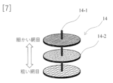
- the discharge step will be explained with reference to FIGS. 5, 6 and 7.
- 12 is a casing tube
- 14 is a stirring device
- 14-1 is a rotating shaft of the stirring device
- 14-2 is a mesh of the stirring device
- 15 is a suction pump.
- the soil inside the casing tube 12 is stirred by the stirring device 14 to loosen the soil, and then sucked and discharged by the suction pump 15.
- the stirring device may be placed inside the casing tube 12 before excavation, or may be inserted into the casing tube 12 after the vibration of the vibrator 11 is stopped.
- An example of the stirring device may be a drill mechanism as shown in FIG.
- the drill function is arranged inside the casing tube 12 before excavation, it is preferable to arrange the drill mechanism above the lowest part of the casing tube 12 so that the drill mechanism does not come into contact with buried objects.
- the stirring device may be a mesh with a stepped structure as shown in FIG. It has a tiered structure with a coarser mesh at the bottom and a finer mesh at the top. It is pushed out toward the bottom of the casing tube 12 while rotating the rotating shaft 14-1 of the stirring device. The soil is loosened greatly and strongly using the coarse mesh stirring device mesh 14-2 at the bottom, and the soil is loosened finely by the fine mesh stirring device mesh 14-2 at the top. By changing the mesh size from coarse to fine in the height direction, it becomes easier to loosen the soil.
- Step 4C After stopping the vibration of the vibrator 11, a telephone pole is connected to the upper surface of the casing tube 12.
- the shape of the casing tube 12 is preferably cylindrical to match the utility pole 22.
- the steps for connecting utility poles will be explained with reference to FIGS. 8, 9, and 10.
- 12 is a casing tube
- 16 is a casing tube bolt hole
- 17 is a casing tube bolt
- 18 is a casing tube bolt mounting bracket
- 19 is a mounting bracket bolt
- 20 is a mounting bracket nut
- 21 is a 22 is a telephone pole
- 23 is a telephone pole bolt hole
- 24 is a telephone pole bolt
- 25 is a telephone pole mounting bracket.
- the casing tube 12 is removed from the vibrator, and the utility pole 22 is placed on the top surface of the casing tube 12.
- the attachment mechanism is omitted.
- casing tube bolt holes 16 are provided in advance in the casing tube 12
- utility pole bolt holes are provided in the utility pole 22 in advance.
- a casing tube bolt fitting 18 is fixed to the casing tube 12 with a casing tube bolt 17.
- a utility pole mounting bracket 25 is fixed to the utility pole 22 with a utility pole bolt 24.
- the casing tube bolt fitting 18 and the utility pole fitting 25 are aligned and fixed with the fitting bolt 19 and the fitting nut 20. Attachment mechanisms are not limited to those described here. It is sufficient that the casing tube 12 and the utility pole 22 are fixed.
- the casing tube 12 is used as the base of the utility pole when erecting the pole, it is possible to omit the labor and effort during pole erecting and improve the efficiency of excavation work. Additionally, the need for backfilling the gap between the pole hole and the utility pole with soil and disposing of waste soil can be omitted, making excavation work more efficient.
- This disclosure can be applied to various industries including the information and communication industry.
- Vibrator 12 Casing tube 13: Mounting vehicle 14: Stirring device 14-1: Stirring device rotating shaft 14-2: Stirring device net 15: Suction pump 16: Casing tube bolt hole 17: Casing tube bolt 18: Casing tube bolt mounting bracket 19: Mounting bracket bolt 20: Mounting bracket nut 21: Soil 22: Utility pole 23: Utility pole bolt hole 24: Utility pole bolt 25: Utility pole mounting bracket 51: Earth auger drill 52: Hole digging pole construction vehicle
Landscapes
- Life Sciences & Earth Sciences (AREA)
- Engineering & Computer Science (AREA)
- Geology (AREA)
- Mining & Mineral Resources (AREA)
- Physics & Mathematics (AREA)
- Environmental & Geological Engineering (AREA)
- Fluid Mechanics (AREA)
- General Life Sciences & Earth Sciences (AREA)
- Geochemistry & Mineralogy (AREA)
- Earth Drilling (AREA)
Priority Applications (3)
| Application Number | Priority Date | Filing Date | Title |
|---|---|---|---|
| US18/864,882 US20250305370A1 (en) | 2022-05-31 | 2022-05-31 | Cave cutting method for pillar construction |
| JP2024524046A JP7798187B2 (ja) | 2022-05-31 | 2022-05-31 | 建柱用穴掘削方法 |
| PCT/JP2022/022208 WO2023233549A1 (ja) | 2022-05-31 | 2022-05-31 | 建柱用穴掘削方法 |
Applications Claiming Priority (1)
| Application Number | Priority Date | Filing Date | Title |
|---|---|---|---|
| PCT/JP2022/022208 WO2023233549A1 (ja) | 2022-05-31 | 2022-05-31 | 建柱用穴掘削方法 |
Publications (1)
| Publication Number | Publication Date |
|---|---|
| WO2023233549A1 true WO2023233549A1 (ja) | 2023-12-07 |
Family
ID=89025936
Family Applications (1)
| Application Number | Title | Priority Date | Filing Date |
|---|---|---|---|
| PCT/JP2022/022208 Ceased WO2023233549A1 (ja) | 2022-05-31 | 2022-05-31 | 建柱用穴掘削方法 |
Country Status (3)
| Country | Link |
|---|---|
| US (1) | US20250305370A1 (https=) |
| JP (1) | JP7798187B2 (https=) |
| WO (1) | WO2023233549A1 (https=) |
Citations (10)
| Publication number | Priority date | Publication date | Assignee | Title |
|---|---|---|---|---|
| JPS5027310A (https=) * | 1973-07-14 | 1975-03-20 | ||
| JPS5894588A (ja) * | 1981-12-01 | 1983-06-04 | 株式会社 多田野鉄工所 | 地中穿孔方法 |
| JPS5894523A (ja) * | 1981-12-01 | 1983-06-04 | Tadano Tekkosho:Kk | 両端開口の中空杭を地中に打込む方法 |
| JPS6016690A (ja) * | 1983-07-08 | 1985-01-28 | 清水建設株式会社 | 掘削機 |
| JPS6367319A (ja) * | 1986-09-09 | 1988-03-26 | Hitachi Constr Mach Co Ltd | 硬さ指数計測装置 |
| JPH04228781A (ja) * | 1990-10-04 | 1992-08-18 | Nippon Chikou Kk | 自立電柱及びその建柱工法 |
| JPH05302315A (ja) * | 1992-04-28 | 1993-11-16 | Hitachi Constr Mach Co Ltd | 地盤硬度の判断装置 |
| JPH08158771A (ja) * | 1995-03-22 | 1996-06-18 | Kyushu Electric Power Co Inc | スクリューアースオーガ装置 |
| JPH1138153A (ja) * | 1997-07-23 | 1999-02-12 | Nippon Telegr & Teleph Corp <Ntt> | 埋設物探知装置 |
| JP2001159288A (ja) * | 1999-12-03 | 2001-06-12 | Tokyo Gas Co Ltd | 立坑掘削装置および立坑掘削方法 |
-
2022
- 2022-05-31 JP JP2024524046A patent/JP7798187B2/ja active Active
- 2022-05-31 US US18/864,882 patent/US20250305370A1/en not_active Abandoned
- 2022-05-31 WO PCT/JP2022/022208 patent/WO2023233549A1/ja not_active Ceased
Patent Citations (10)
| Publication number | Priority date | Publication date | Assignee | Title |
|---|---|---|---|---|
| JPS5027310A (https=) * | 1973-07-14 | 1975-03-20 | ||
| JPS5894588A (ja) * | 1981-12-01 | 1983-06-04 | 株式会社 多田野鉄工所 | 地中穿孔方法 |
| JPS5894523A (ja) * | 1981-12-01 | 1983-06-04 | Tadano Tekkosho:Kk | 両端開口の中空杭を地中に打込む方法 |
| JPS6016690A (ja) * | 1983-07-08 | 1985-01-28 | 清水建設株式会社 | 掘削機 |
| JPS6367319A (ja) * | 1986-09-09 | 1988-03-26 | Hitachi Constr Mach Co Ltd | 硬さ指数計測装置 |
| JPH04228781A (ja) * | 1990-10-04 | 1992-08-18 | Nippon Chikou Kk | 自立電柱及びその建柱工法 |
| JPH05302315A (ja) * | 1992-04-28 | 1993-11-16 | Hitachi Constr Mach Co Ltd | 地盤硬度の判断装置 |
| JPH08158771A (ja) * | 1995-03-22 | 1996-06-18 | Kyushu Electric Power Co Inc | スクリューアースオーガ装置 |
| JPH1138153A (ja) * | 1997-07-23 | 1999-02-12 | Nippon Telegr & Teleph Corp <Ntt> | 埋設物探知装置 |
| JP2001159288A (ja) * | 1999-12-03 | 2001-06-12 | Tokyo Gas Co Ltd | 立坑掘削装置および立坑掘削方法 |
Also Published As
| Publication number | Publication date |
|---|---|
| JP7798187B2 (ja) | 2026-01-14 |
| US20250305370A1 (en) | 2025-10-02 |
| JPWO2023233549A1 (https=) | 2023-12-07 |
Similar Documents
| Publication | Publication Date | Title |
|---|---|---|
| KR100970772B1 (ko) | 오거 및 파일 바이브레이션 햄머 및 이를 이용한 시공방법 | |
| CN106545007B (zh) | 在下部为硬质岩层的地层中成桩的方法 | |
| CN211773656U (zh) | 一种用于拔桩的装置 | |
| KR20070016292A (ko) | 천공 및 항타 작업이 동시에 가능한 파일 시공장치 | |
| WO2023233549A1 (ja) | 建柱用穴掘削方法 | |
| JP2019148070A (ja) | 地下構造物の構築方法 | |
| KR101000866B1 (ko) | 유압 타격식 바이브로 햄머 | |
| JPH10168880A (ja) | 地中埋設障害物の除去装置および同障害物の除去方法 | |
| CN110206483B (zh) | 吸土式全套管成孔装置及其使用方法 | |
| KR101715348B1 (ko) | 스크류파일의 시공장치 | |
| KR101756639B1 (ko) | 말뚝기초 시공방법 | |
| CN117702739A (zh) | 深厚松散土层多级钢护筒埋设方法 | |
| EP4103785B1 (en) | Method for introducing a soil penetrating tool into a soil and underground construction device | |
| JP2000273900A (ja) | エア吸引式排土装置および工法 | |
| JP2018048445A (ja) | 解体方法 | |
| JP2014181470A (ja) | 全周回転掘削機 | |
| JP2697693B2 (ja) | 矢板の打設工法 | |
| JP2000144735A (ja) | 既設杭の撤去装置 | |
| JP3973401B2 (ja) | 地盤締固め工法 | |
| KR101756937B1 (ko) | 다양한 형상의 구근을 형성할 수 있는 말뚝기초 시공방법 | |
| JP2000087678A (ja) | 削孔用土砂及び粉塵飛散防止装置 | |
| CN111058439B (zh) | 一种沉管嵌岩灌注桩施工方法 | |
| JPH05113095A (ja) | シールド工法における発進到達立坑の構造 | |
| JP4781195B2 (ja) | 打込材の打設方法及び先行掘削用打込材 | |
| JP6864277B2 (ja) | 地下埋設体の除去装置及びそれを用いた除去方法 |
Legal Events
| Date | Code | Title | Description |
|---|---|---|---|
| 121 | Ep: the epo has been informed by wipo that ep was designated in this application |
Ref document number: 22944836 Country of ref document: EP Kind code of ref document: A1 |
|
| WWE | Wipo information: entry into national phase |
Ref document number: 2024524046 Country of ref document: JP |
|
| WWE | Wipo information: entry into national phase |
Ref document number: 18864882 Country of ref document: US |
|
| NENP | Non-entry into the national phase |
Ref country code: DE |
|
| 122 | Ep: pct application non-entry in european phase |
Ref document number: 22944836 Country of ref document: EP Kind code of ref document: A1 |
|
| WWP | Wipo information: published in national office |
Ref document number: 18864882 Country of ref document: US |