WO2023228963A1 - ハニカム構造シート及び積層体、並びにこれらの製造方法 - Google Patents
ハニカム構造シート及び積層体、並びにこれらの製造方法 Download PDFInfo
- Publication number
- WO2023228963A1 WO2023228963A1 PCT/JP2023/019241 JP2023019241W WO2023228963A1 WO 2023228963 A1 WO2023228963 A1 WO 2023228963A1 JP 2023019241 W JP2023019241 W JP 2023019241W WO 2023228963 A1 WO2023228963 A1 WO 2023228963A1
- Authority
- WO
- WIPO (PCT)
- Prior art keywords
- honeycomb structure
- sheet
- thickness
- honeycomb
- laminate
- Prior art date
- Legal status (The legal status is an assumption and is not a legal conclusion. Google has not performed a legal analysis and makes no representation as to the accuracy of the status listed.)
- Ceased
Links
Images




Classifications
-
- B—PERFORMING OPERATIONS; TRANSPORTING
- B32—LAYERED PRODUCTS
- B32B—LAYERED PRODUCTS, i.e. PRODUCTS BUILT-UP OF STRATA OF FLAT OR NON-FLAT, e.g. CELLULAR OR HONEYCOMB, FORM
- B32B38/00—Ancillary operations in connection with laminating processes
- B32B38/18—Handling of layers or the laminate
-
- A—HUMAN NECESSITIES
- A61—MEDICAL OR VETERINARY SCIENCE; HYGIENE
- A61L—METHODS OR APPARATUS FOR STERILISING MATERIALS OR OBJECTS IN GENERAL; DISINFECTION, STERILISATION OR DEODORISATION OF AIR; CHEMICAL ASPECTS OF BANDAGES, DRESSINGS, ABSORBENT PADS OR SURGICAL ARTICLES; MATERIALS FOR BANDAGES, DRESSINGS, ABSORBENT PADS OR SURGICAL ARTICLES
- A61L9/00—Disinfection, sterilisation or deodorisation of air
- A61L9/01—Deodorant compositions
- A61L9/014—Deodorant compositions containing sorbent material, e.g. activated carbon
-
- B—PERFORMING OPERATIONS; TRANSPORTING
- B32—LAYERED PRODUCTS
- B32B—LAYERED PRODUCTS, i.e. PRODUCTS BUILT-UP OF STRATA OF FLAT OR NON-FLAT, e.g. CELLULAR OR HONEYCOMB, FORM
- B32B3/00—Layered products comprising a layer with external or internal discontinuities or unevennesses, or a layer of non-planar shape; Layered products comprising a layer having particular features of form
- B32B3/10—Layered products comprising a layer with external or internal discontinuities or unevennesses, or a layer of non-planar shape; Layered products comprising a layer having particular features of form characterised by a discontinuous layer, i.e. formed of separate pieces of material
- B32B3/12—Layered products comprising a layer with external or internal discontinuities or unevennesses, or a layer of non-planar shape; Layered products comprising a layer having particular features of form characterised by a discontinuous layer, i.e. formed of separate pieces of material characterised by a layer of regularly- arranged cells, e.g. a honeycomb structure
Definitions
- the present invention relates to honeycomb structured sheets and laminates, and methods of manufacturing them. This application claims priority based on Japanese Patent Application No. 2022-085774 filed in Japan on May 26, 2022, the contents of which are incorporated herein.
- air conditioning equipment such as air conditioners, air purifiers, humidifiers, and dehumidifiers have become widely used in various living spaces such as residences, offices, factories, and automobiles.
- air conditioners various deodorizing materials and the like are used to obtain purified air.
- a deodorizing material one having a honeycomb structure in which a plurality of liner members and a plurality of corrugated members are bonded to each other and a large number of cell holes penetrating in one direction is formed is known.
- a deodorizing component When a deodorizing component is supported on a liner member or a corrugated member forming a honeycomb structure, the air to be treated comes into contact with the deodorizing component and is purified while passing through the cell holes that serve as flow paths.
- the thickness of the deodorizing material (the length of the cell pores) is generally about 10 mm to 30 mm.
- a honeycomb structure is usually manufactured using a liner member or corrugate member whose length in the direction of the cell pores is about 30 cm to 200 cm, and this is A honeycomb structured sheet of a desired thickness is obtained by cutting along perpendicular planes and used as a deodorizing material.
- a honeycomb structure in which the surface direction of the liner member is arranged horizontally is cut along a plane along the vertical direction (for example, Patent Document 1).
- honeycomb structured sheets have a problem in that the cell pores are easily clogged.
- a honeycomb structure sheet is impregnated with a liquid containing functional agents such as deodorizing components and dried to support these components, the functional agents adhere to foreign substances that block the cell pores, causing further damage. There was a problem that clogging progressed.
- the present invention has been made in view of the above circumstances, and an object of the present invention is to provide a honeycomb structure sheet with less clogging, a laminate obtained by laminating the honeycomb structure sheets, and a method for manufacturing these.
- a honeycomb structure is formed by adhering a plurality of sheet base materials to each other, is partitioned by the plurality of sheet base materials, and has a large number of cell holes penetrating along one direction, which is perpendicular to the one direction.
- a method for manufacturing a honeycomb structure sheet in which the thickness direction is the thickness direction by slicing the honeycomb structure sheet along the plane comprising: A method for manufacturing a honeycomb structure sheet, comprising slicing the honeycomb structure along a plane along a horizontal direction while arranging the honeycomb structure so that the one direction is a vertical direction.
- a honeycomb structured sheet formed by a plurality of sheet base materials adhered to each other, partitioned by the plurality of sheet base materials, and having a large number of cell holes penetrating along the thickness direction, The large number of cell holes are formed in the range of 2000 to 15000 per 254 mm square area, The thickness is 1 to 20 mm, A honeycomb structured sheet, wherein the ratio of cell pores in which 1/3 or more of the area is blocked among the large number of cell pores is 0.1% or less.
- the honeycomb structure sheet according to [4] wherein a functional agent is supported on the sheet base material.
- the honeycomb structure sheet of the present invention has less clogging, and a laminate using this honeycomb structure sheet can efficiently perform functions such as deodorization without excessive pressure loss. Moreover, according to the method for manufacturing a honeycomb structure sheet of the present invention, a honeycomb structure sheet with less clogging can be efficiently manufactured. Moreover, according to the method for manufacturing a laminate of the present invention, a laminate that efficiently exhibits functions such as deodorization can be manufactured without excessive pressure loss.
- FIG. 1 is an exploded perspective view of a laminate according to an embodiment of the present invention.
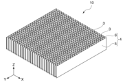
- FIG. 2 is a perspective view of a honeycomb structure used in the present invention.
- FIG. 2 is a schematic perspective view of a slicer that slices a honeycomb structure.
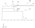
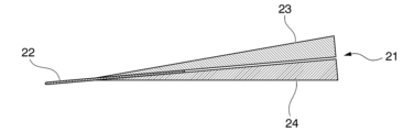
- FIG. 2 is a schematic front view of a slicer that slices a honeycomb structure. It is an explanatory view of a knife unit in a slicer. It is a sectional view of the band knife in the knife unit.
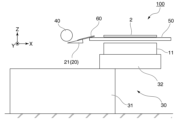
- FIG. 2 is an explanatory diagram showing a situation in which a honeycomb structure is being sliced by a slicer. It is an explanatory view showing the situation where a honeycomb structure sheet was obtained by slicing a honeycomb structure with a slicer.
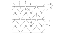
- FIG. 2 is an explanatory diagram of the mechanism of action of the present invention.
- a numerical range expressed using "-" means a range that includes the numerical values written before and after "-" as lower and upper limits.
- Each honeycomb structure sheet 2 in FIG. 1 is a honeycomb structure sheet according to one embodiment of the present invention.
- the honeycomb structure sheet 2 may be used alone for purposes such as deodorization, or may be laminated in plural to form a laminate 1 as shown in FIG.
- the honeycomb structure sheet 2 has a thin thickness and a flat shape that spreads out in a planar shape.
- the thickness of the honeycomb structure sheet 2 (length in the Z direction in FIG. 1) is 1 to 20 mm. If the thickness of the honeycomb structure sheet 2 is 1 mm or more, it is easy to ensure processing accuracy during manufacturing. If the thickness of the honeycomb structure sheet 2 is 20 mm or less, there is a great advantage in adopting the deodorizing sheet manufacturing method of the present invention, which will be described later.
- the thickness of the honeycomb structure sheet 2 (length in the Z direction in FIG. 1) is preferably 1 to 20 mm, more preferably 1 to 15 mm, and 1 to 20 mm. 10 mm is more preferable, and 2.5 to 10 mm is particularly preferable. If the thickness of the honeycomb structure sheet 2 is at least the lower limit of the above-mentioned preferable range, processing accuracy during manufacturing can be easily ensured. As long as the thickness of the honeycomb structure sheet 2 is below the upper limit of the above-mentioned preferable range, the thickness of the entire laminate 1 will not become excessive even if a plurality of honeycomb structure sheets 2 are piled up.
- the thickness of the honeycomb structure sheet 2 is preferably 1 to 50 mm, and 2.5 to 30 mm. It is more preferably 5 to 20 mm, even more preferably 5 to 10 mm. If the thickness of the honeycomb structure sheet 2 is at least the lower limit of the above-mentioned preferred range, it will be easy to ensure the necessary strength when used for purposes such as deodorization. If the thickness of the honeycomb structure sheet 2 is equal to or less than the upper limit of the above-mentioned preferable range, there is a great advantage in adopting the method for producing a deodorizing sheet of the present invention, which will be described later.
- the honeycomb structure sheet 2 is composed of a plurality of sheet base materials 4 adhered to each other.
- the plurality of sheet base materials 4 are all arranged so that the surface direction thereof extends along the thickness direction (Z direction).
- a large number of cell holes 3 partitioned by the sheet base materials 4 are formed between the plurality of sheet base materials 4 .
- the cell holes 3 are open at both the upper and lower ends in the thickness direction, and penetrate in the thickness direction (Z direction).
- the cell holes 3 serve as channels through which gas such as air to be treated passes.
- the shape of the cell pores 3 in plan view is not particularly limited, and in the illustrated example it is a chevron-shaped shape (approximately triangular shape), but other shapes may be used, such as a square shape, a rhombus shape, a hexagonal shape, a circular shape, etc. You can.
- the plurality of cell holes 3 are arranged regularly or irregularly at narrow intervals in vertical, horizontal, diagonal, etc. directions within the XY plane.
- 2,000 to 15,000 cell holes 3 are formed per 254 mm square (10 inch square) area.
- the number of cell holes 3 per 10 inch square area is preferably 2,000 to 15,000, more preferably 4,000 to 12,000. If the number of cell holes 3 per 10 inch square area is 2000 or more, efficient deodorization can be achieved. If the number of cell holes 3 per 10 inch square area is 15,000 or less, the flow of air passing therethrough will not be obstructed.
- the plurality of sheet base materials 4 are composed of a combination of a plurality of liner members 5 that extend linearly in a plan view and a plurality of corrugated members 6 that are wavy in a plan view. preferred from the point of view of production.
- FIG. 1 shows an example in which liner members 5 and corrugated members 6 are alternately stacked along the X direction.
- the sheet base material 4 is not limited to a mode in which the liner members 5 and the corrugated members 6 are alternately laminated, and may have a portion where the corrugated members 6 are adjacent to each other and bonded to each other, for example. Further, there may be a portion where the liner members 5 are adjacent to each other and bonded to each other.
- the pitch of the corrugated members 6 constituting the sheet base material 4 is preferably 2 to 8 mm, more preferably 4 to 6 mm. Further, the height of the corrugated member 6 is preferably 1 to 5 mm, more preferably 2 to 4 mm.
- the pitch and height of the corrugated members 6 do not need to be uniform; for example, the corrugated members 6 may be stacked along the X direction and have different heights and pitches for each stage. Further, when corrugated members 6 having the same height and pitch are used in each stage, the phases may be the same or different.
- the material constituting the sheet base material 4 is not particularly limited as long as it can maintain its shape, and examples thereof include inorganic materials, organic materials, or combinations thereof, such as paper, nonwoven fabric, woven fabric, and plastic film.
- the material constituting the sheet base material 4 is preferably one that can support functional agents and the like. Furthermore, functional agents and the like may be filled internally or externally.
- paper and nonwoven fabrics using inorganic fibers or organic fibers are preferable because they absorb liquid through capillary action and easily retain chemical liquids such as functional agents. Paper and nonwoven fabrics can be easily formed by wet paper making using inorganic fibers and organic fibers.
- inorganic fibers include glass fibers, ceramic fibers, carbon fibers, and the like. Among them, glass fiber is preferable from the viewpoint of safety for the human body and cost.
- Examples of organic fibers include pulp and resin fibers.
- the sheet base material 4 preferably contains inorganic fibers in an amount of 30% by mass or more, more preferably 40% by mass or more, and still more preferably 50% by mass or more.
- inorganic fibers high heat resistance, high heat insulation properties, nonflammability, etc. can be provided.
- the material that occupies the largest mass proportion is preferably inorganic fiber.
- the sheet base material 4 is constructed using a combination of inorganic fibers and organic fibers. By containing organic fibers in addition to inorganic fibers, moldability is improved.
- the basis weight of the sheet base material 4 is not particularly limited, but in the case of paper or nonwoven fabric, it is preferably 10 to 100 g/m 2 , more preferably 15 to 60 g/m 2 . If the basis weight is at least the lower limit of the preferred range, the sheet base material 4 formed into a corrugated shape or the like can have sufficient strength. If the basis weight is below the upper limit of the preferable range, the thickness can be suppressed and cell holes 3 with a sufficient cross-sectional area can be easily formed, so that pressure loss can also be suppressed.
- the honeycomb structure sheet 2 further includes a functional agent supported on the sheet base material 4 in addition to the sheet base material 4.
- Functional agents include, for example, adsorbents that have the function of adsorbing and deodorizing malodorous components, antibacterial agents and antifungal agents that have antibacterial and antifungal functions, ozone decomposers that have the function of decomposing ozone, and flame retardants. . These may be used alone or in combination of two or more.
- adsorbent examples include, but are not particularly limited to, known ones such as activated carbon; zeolites such as mordenite, ferrierite, and molecular sieves; silica gel; alumina gel; acid hydrazide, azole compounds, and organic acids.
- Antibacterial agents and antifungal agents are not particularly limited, but include known antibacterial agents such as silver-containing antibacterial agents.
- the ozone decomposer is not particularly limited, but may include known ones such as a manganese catalyst type ozone decomposer, a copper/manganese catalyst type ozone decomposer, an activated carbon type ozone decomposer, and the like.
- the functional agent is not limited to these, and various other known functional agents can be used.
- the functional agent may be in various forms such as powder, granules, and fibers.
- the method of supporting the functional agent on the sheet base material 4 and the functional agent may be held inside the sheet base material 4 or may be attached to the surface of the sheet base material 4.
- the sheet base material 4 may be coated with an impregnating liquid containing a functional agent, or the sheet base material 4 may be impregnated with the impregnating liquid.
- the ratio of the cell pores 3 in which 1/3 or more of the area of the entire cell pores 3 is blocked (hereinafter referred to as "clogging rate") is 0.1% or less. Since the honeycomb structure sheet 2 has a clogging rate of 0.1% or less, it can efficiently perform functions such as deodorization without excessive pressure loss.
- the standard deviation ⁇ of the thickness of the honeycomb structure sheet 2 of this embodiment is preferably 0.2 mm or less, preferably 0.15 mm or less, and more preferably 0.1 mm or less. Since the standard deviation ⁇ of the thickness of the honeycomb structure sheet 2 is less than or equal to a preferable value, processing accuracy is improved when it is formed into a laminate.
- FIG. 1 is an exploded perspective view of a laminate 1 according to one embodiment of the present invention.
- the laminate 1 is used, for example, to remove components to be removed from a gas such as air, and is used, for example, in an air cleaner or the like for purposes such as deodorization and foreign matter removal.
- the laminate 1 includes a plurality of honeycomb structured sheets 2. There is no particular limitation on the number of layers of honeycomb structure sheets 2 constituting the laminate 1, but it can be, for example, 2 to 10 layers.
- the laminate 1 is made by laminating a plurality of honeycomb structure sheets 2 in the thickness direction (Z direction in FIG. 1) and bonding one side of the honeycomb structure sheets 2 adjacent to each other in the thickness direction with an adhesive or the like. It is constructed by integrating 2.
- the plurality of honeycomb structure sheets 2 constituting the laminate 1 may be stacked so that the positions of the cell holes 3 overlap and the cell holes 3 communicate linearly, or They may be stacked such that their positions are shifted and the respective cell holes 3 communicate through complicated paths.
- Methods for shifting the position of each cell hole 3 include a method in which the liner members 5 of each honeycomb structure sheet 2 are stacked so as to intersect, and a method in which the phase of the corrugated members 6 constituting each honeycomb structure sheet 2 is shifted. , a method of combining corrugated members 6 having different pitches and heights as the corrugated members 6 constituting each honeycomb structure sheet 2, and the like.
- each honeycomb structure sheet 2 communicates in a straight line or a shape close to a straight line, the smaller the pressure loss can be.
- the positions of the cell holes 3 of each honeycomb structure sheet 2 are shifted and the cell holes 3 of each honeycomb structure sheet 2 are made to communicate through a complicated path, the sheet base material 4 and the air etc., the contact efficiency increases.
- the laminate 1 may be formed by laminating a plurality of types of honeycomb structure sheets 2 carrying different types of functional agents. Thereby, one laminate 1 can exhibit many different functions.
- the sheet base materials 4 of the separate honeycomb structure sheets 2 carry functional agents that would impair the function of one of them if coexisting in one system.
- the activated carbon acts as a catalyst
- the acid hydrazide functions as a catalyst.
- the group (amine group) is oxidized, resulting in a decrease in performance against aldehydes. Therefore, by preparing a honeycomb structure sheet 2 carrying activated carbon and a honeycomb structure sheet 2 carrying acid hydrazide, respectively, and stacking them, the effects of activated carbon and acid hydrazide can be exerted together.
- the laminate 1 can reduce pressure loss by laminating honeycomb structure sheets 2 with a low clogging rate. Furthermore, by stacking the honeycomb structure sheets 2 with a small standard deviation ⁇ of thickness, leakage of air and the like from the joints between the honeycomb structure sheets 2 is suppressed. Therefore, functions such as deodorization can be efficiently performed.
- the honeycomb structure sheet 2 of the above embodiment can be manufactured by slicing the honeycomb structure 10 as shown in FIG. 2 in a plane perpendicular to one direction through which the cell holes 3 pass.
- the honeycomb structure 10 is constructed by adhering a plurality of sheet base materials 4 to each other.
- the plurality of sheet base materials 4 are all arranged so that the surface direction thereof extends along the thickness direction (Z direction).
- the honeycomb structure 10 has the same structure as the honeycomb structure sheet 2 except for the difference in thickness, and the preferred embodiments are also the same.
- the thickness of the honeycomb structure 10 (length in the Z direction in FIG. 2) is preferably 50 to 2000 mm, more preferably 100 to 1000 mm, even more preferably 100 to 500 mm, and particularly preferably 150 to 300 mm. If the thickness of the honeycomb structure 10 is at least the lower limit of the above-mentioned preferable range, a large number of honeycomb structure sheets 2 can be manufactured from one honeycomb structure 10, which is efficient. If the thickness of the honeycomb structure 10 is less than or equal to the upper limit of the preferable range, it is easy to avoid increasing the size of the device for slicing the honeycomb structure 10.
- the size of the honeycomb structure 10 in plan view is preferably 10 to 2000 mm, more preferably 10 to 1000 mm, even more preferably 20 to 500 mm, particularly preferably 100 to 500 mm in each of the X direction and the Y direction. If the size of the honeycomb structure 10 in plan view is equal to or larger than the lower limit of the above-mentioned preferable range, a large-area honeycomb structure sheet 2 can be manufactured. Further, since a large number of honeycomb structure sheets 2 can be manufactured from one honeycomb structure 10, it is efficient. If the size of the honeycomb structure 10 in plan view is equal to or less than the upper limit of the preferable range, it is easy to avoid increasing the size of the device for slicing the honeycomb structure 10.
- the sheet base material 4 is composed of a liner member 5 and a corrugated member 6.
- the liner member 5 and the corrugated member 6 may be made of the same material or different materials.
- a continuous corrugated member 6 which is corrugated with a corrugator and provided with corrugations (irregularities) and a continuous liner member 5 are bonded together to produce a single-wave molded body. Then, the single-wave molded body is cut to have a predetermined area to obtain a plurality of single-wave molded bodies.
- a honeycomb structure 10 is obtained by bonding and laminating the surface of the liner member 5 of one wave molded body and the surface of the corrugated member 6 of another single wave molded body.
- organic glues such as ethylene vinyl acetate copolymer and polyvinyl alcohol, and inorganic glues such as colloidal silica, water glass, sepiolite, and alumina sol are used as appropriate. can.
- the slicer 100 of this embodiment includes a knife unit 20 having a band knife 21, a moving table 30 that places the honeycomb structure 10 thereon and moves in the direction of the band knife 21, and a slicer 100 that moves the honeycomb structure 10 with the band knife 21.
- Consisting of a presser roll 40 that presses the honeycomb structure sheet in front of 21, a fixed table 50 on which the honeycomb structure sheet obtained by slicing with the band knife 21 is placed, and a guide plate 60 that guides the obtained honeycomb structure sheet onto the fixed table 50. has been done. Note that in FIG. 3, illustration of the fixed table 50 is omitted for convenience.
- the knife unit 20 basically includes an endless band knife 21 and a pair of pulleys 25 and 26.
- a band knife 21 is wound around the pair of pulleys 25 and 26, and one (lower) band knife 21 (hereinafter referred to as “lower band knife 21”) is hung between the pair of pulleys 25 and 26.
- the other (upper) band knife 21 (hereinafter referred to as the “upper band knife 21") is maintained in a tensioned state by a pair of pulleys 25 and 26.
- the rotation axes of the pair of pulleys 25 and 26 are rotatably installed substantially parallel to the horizontal direction. Then, as one or both of the pair of pulleys 25 and 26 rotates, the band knife 21 is rotated, and the lower band knife 21 and the upper band knife 21 are moved along the horizontal plane (XY plane in FIG. 5). It is designed to run with
- the pair of pulleys 25 and 26 are movable in the vertical direction (Z direction) by a drive mechanism (not shown). In accordance with the vertical movement of the pair of pulleys 25 and 26, the horizontal planes on which the lower band knife 21 and the upper band knife 21 respectively travel also move up and down.
- the running direction of the lower band knife 21 is approximately the Y direction in FIG. 5, but it is slightly inclined as shown in FIG. Note that the X direction is the direction in which the honeycomb structure 10 moves in the slicer 100, and the Y direction is a direction perpendicular to the X direction in the horizontal plane.
- the band knife 21 is not particularly limited, it may be basically composed of a blade portion 22, an upper blade holder 23, and a lower blade holder 24, as shown in FIG.
- the blade portion 22 has one end exposed from the upper blade holder 23 and the lower blade holder 24 as a cutting edge, and the other end is sandwiched between the upper blade holder 23 and the lower blade holder 24.
- the movable table 30 has a fixed base 31 and a slide part 32 slidably provided on the upper surface of the fixed base 31.
- the slide portion 32 is configured to move in the X direction or the reverse X direction in FIGS. 3 and 4 with the honeycomb structure 10 placed horizontally.
- the slide portion 32 has a fixing mechanism for fixing the honeycomb structure 10 to the upper surface.
- the press roll 40 is arranged in front of the lower band knife 21 traveling (near the reverse X direction), and prevents the honeycomb structure 10 in the moving direction (the tip in the X direction) from lifting off from the movable base of the moving table 30. It looks like this.
- the fixed table 50 is arranged on the X direction side of the knife unit 20.
- the lower surface of the fixed table 50 is located slightly above the position of the cutting edge of the blade portion 22 of the band knife 21.
- the guide plate 60 is stretched between the band knife 21 and the fixed table 50 so that the fixed table 50 side is higher.
- a method for manufacturing a honeycomb structure sheet according to one aspect of the present invention will be described, taking as an example a case where the honeycomb structure 10 of FIG. 2 is sliced using the slicer 100.
- the slide portion 32 of the movable table 30 is placed at a position (initial position) that does not overlap the knife unit 20 in the X direction.
- the vertical positions of the pair of pulleys 25 and 26 are adjusted. Specifically, when the slide part 32 is moved in the X direction, the lower band knife 21 is moved to a position lowered by the thickness of the obtained honeycomb structure sheet 2 from the upper surface of the honeycomb structure 10 to be placed. Adjust to a position where the cutting edge of the blade part 22 (hereinafter sometimes referred to as "the cutting edge of the band knife 21") comes into contact.
- the honeycomb structure 10 is placed on the slide portion 32.
- the honeycomb structure 10 is arranged so that one direction through which the many cell holes 3 penetrate is the vertical direction (Z direction in FIGS. 3 and 4).
- the slide portion 32 is moved in the X direction.
- the cutting edge of the band knife 21 comes into contact with the honeycomb structure 10. Since the vertical positions of the pair of pulleys 25 and 26 have been adjusted in advance, the vertical position where the cutting edge of the band knife 21 contacts is lowered from the upper surface of the honeycomb structure 10 by the thickness of the honeycomb structure sheet 2 obtained. It's the location.
- the cutting edge of the band knife 21 advances while slicing the honeycomb structure 10 horizontally, as shown in FIG. It is separated into Further, the remaining sliced portion advances in the X direction below the fixed table 50 without contacting the fixed table 50.
- the honeycomb structure sheet 2 is completely separated by the band knife 21 and transferred from the guide plate 60 onto the fixed table 50, as shown in FIG. Further, the remaining portion (remaining structure 11) of the separated honeycomb structure sheet 2 remains below the fixed table 50, and the manufacturing of the first honeycomb structure sheet 2 is completed.
- the slide portion 32 is moved in the reverse X direction and returned to the initial position, and the remaining structure 11 is used as a new honeycomb structure 10.
- the vertical positions of the pair of pulleys 25 and 26 are lowered by the thickness of the honeycomb structure sheet 2. That is, the vertical positions of the pair of pulleys 25 and 26 are adjusted to a position where the cutting edge of the band knife 21 comes into contact with a position that is lower than the upper surface of the new honeycomb structure 10 by the thickness of the obtained honeycomb structure sheet 2.
- honeycomb structure sheets 2 can be obtained. Note that since the uppermost surface of the honeycomb structure 10 is somewhat lacking in flatness, the first honeycomb structure sheet 2 may be discarded and the second and subsequent honeycomb structure sheets 2 may be used.
- a honeycomb structured sheet 2 with a low clogging rate can be obtained. Further, the uniformity of the thickness is also improved. It is presumed that this is because sliding in the horizontal direction prevents the adhesive or the like from causing clogging. The situation when slicing along a plane along the vertical direction in a state where one direction through which a large number of cell holes 3 pass is the horizontal direction will be described with reference to FIG.
- the sheet base material 4 consisting of the liner member 5 and the corrugated member 6 is adhered to each other with an adhesive 7. It is presumed that when the honeycomb structure 10 is sliced along a vertical plane, the adhesive 7 melts due to frictional heat from the knife and drips in the vertical direction, which is the cause of clogging.
- the honeycomb structure 10 is sliced along the plane along the horizontal direction, even if the adhesive 7 melts due to the frictional heat generated by the knife, the melted adhesive 7 will be transferred to the sheet base material 4 (in the thickness direction of the paper in FIG. 9). It is presumed that since it sag along, it is difficult to close the gap between the sheet base materials 4, that is, the cell holes 3.
- the knife is a band knife 21 that runs in one direction, it is thought that the generation of frictional heat can be further reduced. Therefore, according to the method for manufacturing a honeycomb structure sheet of the above aspect, rubbing and melting of the adhesive 7 due to generation of frictional heat are suppressed, so the honeycomb structure has a low clogging rate and improved thickness uniformity. It is assumed that structural sheet 2 is obtained.
- the obtained honeycomb structure sheet 2 can be used as a deodorizing material or the like by coating and impregnating it with a liquid containing a functional agent such as an adsorbent (hereinafter referred to as "functional agent-containing liquid").
- the functional agent-containing liquid may contain a binder and a thickener in addition to the above-mentioned functional agent. Thickeners are used when it is difficult to constantly stir the coating liquid when coating and impregnating the honeycomb structure sheet 2 with a functional agent-containing liquid, or when the coating liquid is an emulsion containing water or a binder component, activated carbon, etc. It is particularly suitable for use in cases where the functional agent is separated into porous functional agents.
- the functional agent-containing liquid may contain a colorant, a wetting agent, a paper strength improver, a waterproofing agent, a pH adjuster, an antifoaming agent, a preservative, etc., as necessary.
- the medium for the functional agent-containing liquid is not particularly limited, but water, alcohol, etc. can be used. After coating and impregnating the functional agent-containing liquid, drying is performed.
- the honeycomb structure sheet 2 obtained by slicing the honeycomb structure 10 can be used as a deodorizing material or the like as it is. .
- each honeycomb structure sheet 2 may be roughly cut in advance so that the outer edge in the XY plane of FIG. 1 is slightly larger than the outer edge of the final laminate 1. preferable. Further, after laminating and adhering, it is preferable to precisely cut the outer edge so that the final laminate 1 has an appropriate size.
- ⁇ Measurement method> [Thickness of honeycomb structure sheet] Using a coolant proof micrometer (manufactured by Mitutoyo), the thickness of the honeycomb structure sheet of each example was measured at 20 locations, and the average value and standard deviation thereof were determined. The 20 measurement points were randomly selected and evenly distributed so as not to be biased toward any one part.
- the honeycomb structure used in each example consisted of a liner member made of glass paper PHN-50G manufactured by Oji F-Tex (glass nonwoven fabric made of glass fiber and pulp, basis weight 50 g/m 2 ), and a liner member made of a corrugated material. Corrugated members (pitch 5 mm, height 2 mm) were alternately laminated to obtain a honeycomb structure having a height of 300 mm, a size of 254 mm (1 inch) square, and approximately 12,000 cell holes.
- Examples 1 to 5> By slicing the above honeycomb structure using the slicer 100 described in the above embodiment and according to the method described in the above embodiment to have the set thickness shown in Table 1, the honeycomb structure sheet of each example is sliced. I got it.
- the slice plane is a plane perpendicular to one direction through which a large number of cell holes pass, and is a plane along the horizontal direction.
- Table 1 shows the average thickness, standard deviation of thickness, number of clogged cells (after cutting), and clogging rate (after cutting) of the honeycomb structured sheets of each example obtained.
- the obtained honeycomb structured sheets of each example were placed in a functional material-containing liquid containing activated carbon, silica, organic acid, and acrylic resin, having a viscosity of 12 seconds (Zahn cup #2), and a solid content concentration of 35% by mass. After impregnating and adhering it so that the coating amount per volume (cm 3 ) of the honeycomb structure sheet was 0.45 g (approximately 0.16 g as a dry coating amount), it was heated at 150 ° C. in a blow dryer. It was dried for 30 minutes.
- Table 1 shows the number of clogged cells (after impregnation) and the clogging rate (after impregnation) of the obtained honeycomb structure sheet of each example after impregnation.
- the honeycomb structure sheet of each example was obtained by slicing the above honeycomb structure using a vertical cutter (manufactured by Sakura Kikai) to the set thickness shown in Table 2.
- the slice plane is a plane perpendicular to one direction through which a large number of cell holes pass, and is a plane along the vertical direction.
- Table 2 shows the average thickness, standard deviation of thickness, number of clogged cells (after cutting), and clogging rate (after cutting) of the honeycomb structured sheets of each example obtained.
- the obtained honeycomb structured sheets of each example were placed in a functional material-containing liquid containing activated carbon, silica, organic acid, and acrylic resin, having a viscosity of 12 seconds (Zahn cup #2), and a solid content concentration of 35% by mass. After impregnating and adhering it so that the coating amount per volume (cm 3 ) of the honeycomb structure sheet was 0.45 g (approximately 0.16 g as a dry coating amount), it was heated at 150 ° C. in a blow dryer. It was dried for 30 minutes.
- Table 2 shows the number of clogged cells (after impregnation) and the clogging rate (after impregnation) of the obtained honeycomb structure sheet of each example after impregnation.
- Table 2 shows the number of clogged cells (after impregnation) and the clogging rate (after impregnation) of the obtained honeycomb structure sheet of each example after impregnation.
- the honeycomb structured sheets of comparative examples all had large standard deviations in thickness and low processing accuracy.
- the clogging rate after cutting was high, and the clogging rate after impregnation was even higher.
- the laminate of the comparative example had a large pressure loss. Furthermore, it has been found that when the slice plane is vertical, it is difficult to manufacture a product thinner than 3 mm in thickness.
Landscapes
- Health & Medical Sciences (AREA)
- Chemical & Material Sciences (AREA)
- Engineering & Computer Science (AREA)
- Materials Engineering (AREA)
- Epidemiology (AREA)
- Life Sciences & Earth Sciences (AREA)
- Animal Behavior & Ethology (AREA)
- General Health & Medical Sciences (AREA)
- Public Health (AREA)
- Veterinary Medicine (AREA)
- Laminated Bodies (AREA)
- Disinfection, Sterilisation Or Deodorisation Of Air (AREA)
Abstract
Description
本願は、2022年5月26日に、日本に出願された特願2022-085774号に基づき優先権を主張し、その内容をここに援用する。
このハニカム構造体を切断するにあたり、従来、ライナー部材の面方向を水平方向として配置したハニカム構造体を、鉛直方向に沿う面で切断することが行われていた(例えば特許文献1)。
また、ハニカム構造シートを、脱臭成分等の機能剤を含む液に含浸・乾燥させ、これらの成分を担持させようとすると、セル孔を塞ぐ異物に対して、機能剤が付着することにより、さらに目詰まりが進行してしまう問題があった。
本発明は、上記事情に鑑みてなされたものであって、目詰まりの少ないハニカム構造シートと、このハニカム構造シートを積層した積層体、並びにこれらの製造方法を提供することを課題とする。
[1]複数のシート基材が互いに接着してなり、前記複数のシート基材により区画され、一方向に沿って貫通する多数のセル孔が形成されたハニカム構造体を、前記一方向と直交する面でスライスし、前記一方向が厚み方向となるハニカム構造シートを製造する方法であって、
前記ハニカム構造体を、前記一方向が鉛直方向となるように配置した状態で、水平方向に沿う面でスライスすることを特徴とする、ハニカム構造シートの製造方法。
[2]さらに、機能剤を含む液を塗布・含浸させる[1]に記載のハニカム構造シートの製造方法。
[3][1]又は[2]に記載のハニカム構造シートの製造方法で得られたハニカム構造シートを、複数積層する積層体の製造方法。
[4]複数のシート基材が互いに接着してなり、前記複数のシート基材により区画され、厚み方向に沿って貫通する多数のセル孔が形成されたハニカム構造シートであって、
前記多数のセル孔が、254mm四方の面積あたり、2000~15000個形成されており、
厚みが1~20mmであり、
前記多数のセル孔の内、1/3以上の面積が閉塞しているセル孔の割合が0.1%以下である、ハニカム構造シート。
[5]前記シート基材に機能剤が担持された、[4]に記載のハニカム構造シート。
[6][4]又は[5]に記載のハニカム構造シートが、複数積層した積層体。
図1における各々のハニカム構造シート2は、本発明の1実施形態に係るハニカム構造シートである。
ハニカム構造シート2は、1枚単独で脱臭等の用途に供してもよいし、図1に示すように複数積層して積層体1としてもよい。
ハニカム構造シート2の厚みが1mm以上であれば、製造時の加工精度を確保しやすい。ハニカム構造シート2の厚みが20mm以下であれば、後述の本発明の脱臭シートの製造方法を採用するメリットが大きい。
ハニカム構造シート2の厚みが上記好ましい範囲の下限値以上であれば、製造時の加工精度を確保しやすい。ハニカム構造シート2の厚みが上記好ましい範囲の上限値以下であれば、複数のハニカム構造シート2を重ねても積層体1全体の厚みが過大とならない。
ハニカム構造シート2の厚みが上記好ましい範囲の下限値以上であれば、脱臭等の用途に供するにあたり、必要な強度を確保しやすい。
ハニカム構造シート2の厚みが上記好ましい範囲の上限値以下であれば、後述の本発明の脱臭シートの製造方法を採用するメリットが大きい。
複数のシート基材4の間には、シート基材4によって区画された多数のセル孔3が形成されている。セル孔3は、厚み方向の上下の両端において開口しており、厚み方向(Z方向)に沿って貫通している。セル孔3は、例えば処理対象である空気等の気体が通る流路となる。
セル孔3の10インチ四方の面積あたりの数が2000個以上であれば効率よく脱臭ができる。セル孔3の10インチ四方の面積あたりの数が15000個以下であれば通過する空気の流れを妨げない。
図1では、ライナー部材5とコルゲート部材6とが交互にX方向に沿って積層されている例を示している。
シート基材4は、ライナー部材5とコルゲート部材6とが交互に積層される態様に限定されず、例えば、コルゲート部材6同士が隣接して互いに接着している部分があってもよい。また、ライナー部材5同士が隣接して互いに接着している部分があってもよい。
コルゲート部材6のピッチと高さは、均一である必要はなく、例えば、X方向に沿って積層され、各段に異なる高さやピッチのコルゲート部材6を用いてもよい。また、各段に同一の高さやピッチのコルゲート部材6を用いた場合、その位相は同一でも異なっていてもよい。
特に、無機繊維、有機繊維を用いた紙、不織布は、毛細管現象で吸液し機能剤等の薬液を保持しやすいことから好ましい。紙、不織布は、無機繊維、有機繊維を用い、湿式抄紙により容易に形成することができる。
無機繊維としては、ガラス繊維、セラミック繊維、炭素繊維等が挙げられる。中でもガラス繊維は、人体に対する安全面やコストの点で好ましい。有機繊維としては、パルプ、樹脂繊維等が挙げられる。
シート基材4を構成する材料の内、最も大きい質量割合を占める材料は無機繊維であることが好ましい。
また、シート基材4を、無機繊維と有機繊維とを併用して構成することも好ましい。無機繊維に加えて有機繊維を含有することにより、成形性が向上する。
抗菌剤や防カビ剤としては、特に限定されないが、銀含有抗菌剤等の公知のものを挙げることができる。
オゾン分解剤としては、特に限定されないが、マンガン触媒系オゾン分解剤、銅・マンガン触媒系オゾン分解剤、活性炭系オゾン分解剤等の公知のものを挙げることができる。
ハニカム構造シート2は、目詰まり率が0.1%以下であることにより、圧力損失を過大にすることなく、効率的に脱臭等の機能を発揮することができる。
ハニカム構造シート2は、厚みの標準偏差σが好ましい値以下であることにより、積層体とした場合の加工精度が向上する。
図1は、本発明の1実施形態に係る積層体1の分解斜視図である。積層体1は、例えば空気等の気体から除去対象成分を除去する際に用いるものであり、例えば空気清浄機等において脱臭や異物除去等の目的で使用される。積層体1は、複数のハニカム構造シート2を備える。積層体1を構成するハニカム構造シート2の積層数に特に限定はないが、例えば2~10層とすることができる。
各々のセル孔3の位置をずらす方法としては、各々のハニカム構造シート2のライナー部材5が交差するようにして積層する方法、各々のハニカム構造シート2を構成するコルゲート部材6の位相をずらす方法、各々のハニカム構造シート2を構成するコルゲート部材6として、ピッチや高さが異なるものを組み合わせる方法、等が挙げられる。
特に、1つの系に共存させると一方の機能が損なわれるような機能剤を、別個のハニカム構造シート2のシート基材4にそれぞれ担持させると好ましい。
そこで、活性炭を担持させたハニカム構造シート2と酸ヒドラジドを担持させたハニカム構造シート2とを各々用意し、これら等を積層すれば、活性炭と酸ヒドラジドの効果を共に発揮させることができる。
また、厚みの標準偏差σが小さいハニカム構造シート2を積層することにより、ハニカム構造シート2同士の接合箇所から、空気等が漏れることが抑制される。そのため、効率的に脱臭等の機能を発揮することができる。
上記実施形態のハニカム構造シート2は、図2に示すようなハニカム構造体10を、セル孔3が貫通する一方向と直交する面でスライスすることにより製造することができる。
ハニカム構造体10は、図2に示すように、複数のシート基材4が互いに接着して構成されている。複数のシート基材4は、いずれもその面方向が厚み方向(Z方向)に沿うように配置されている。
ハニカム構造体10は、厚みが異なる他は、ハニカム構造シート2と同様に構成されており、好ましい態様も同じである。
ハニカム構造体10の厚みが上記好ましい範囲の下限値以上であれば、1つのハニカム構造体10から多数枚のハニカム構造シート2を製造できるので、効率的である。
ハニカム構造体10の厚みが上記好ましい範囲の上限値以下であれば、ハニカム構造体10をスライスするための装置の大型化を回避しやすい。
ハニカム構造体10の平面視の大きさが上記好ましい範囲の下限値以上であれば、大面積のハニカム構造シート2を製造できる。また、1つのハニカム構造体10から多数枚のハニカム構造シート2を製造できるので、効率的である。
ハニカム構造体10の平面視の大きさが上記好ましい範囲の上限値以下であれば、ハニカム構造体10をスライスするための装置の大型化を回避しやすい。
ハニカム構造体10の製造方法に特に限定はないが、前記シート基材4をライナー部材5とコルゲート部材6とで構成することが好ましい。ライナー部材5,コルゲート部材6は、同じ材料であっても、異なる材料であってもよい。
図3、図4を参照しつつ、本態様のハニカム構造シートの製造方法に使用するスライサーの一態様について説明する。
図4に示すように、本態様のスライサー100は、バンドナイフ21を有するナイフユニット20と、ハニカム構造体10を載せてバンドナイフ21方向に移動する移動テーブル30と、ハニカム構造体10をバンドナイフ21手前で押さえる押さえロール40と、バンドナイフ21でスライスして得られたハニカム構造シートを載置する固定テーブル50と、得られたハニカム構造シートを固定テーブル50上に導く案内板60とで構成されている。なお、図3においては、便宜上固定テーブル50の図示を省略している。
一対のプーリー25、26には、バンドナイフ21が巻き付けられており、一対のプーリー25、26の間に掛けられた一方(下方)のバンドナイフ21(以下「下方のバンドナイフ21」という。)と、他方(上方)のバンドナイフ21(以下「上方のバンドナイフ21」という。)は、一対のプーリー25、26により緊張状態を保っている。
なお、X方向はハニカム構造体10のスライサー100における移動方向であり、Y方向は、水平面内においてX方向と直交する方向である。
スライド部32は、ハニカム構造体10を水平に載置した状態で図3、図4のX方向又は逆X方向に移動するようになっている。スライド部32は、ハニカム構造体10を上面に固定するための固定機構を有している。
案内板60は、バンドナイフ21と固定テーブル50との間に固定テーブル50側が高くなるように掛け渡されている。
以下に、上記スライサー100を用いて、図2のハニカム構造体10をスライスする場合を例にとって、本発明の一態様に係るハニカム構造シートの製造方法について説明する。
まず、移動テーブル30のスライド部32を、X方向において、ナイフユニット20と重ならない位置(初期位置)に配置する。
また、ハニカム構造シート2が分離された残りの部分(残部構造体11)は、固定テーブル50の下方に残り、1枚目のハニカム構造シート2の製造が終了する。
そして、一対のプーリー25、26の上下位置を、ハニカム構造シート2の厚み分だけ下降させる。すなわち、新たなハニカム構造体10の上面から、得られるハニカム構造シート2の厚み分だけ下がった位置に、バンドナイフ21の刃先が接触する位置に一対のプーリー25、26の上下位置を調整する。
そして、さらに、スライド部32を初期位置に戻して、一対のプーリー25、26の上下位置を、ハニカム構造シート2の厚み分だけ下降させてからスライド部32をX方向に移動させることを繰り返すことにより、多数枚のハニカム構造シート2を得ることができる。
なお、ハニカム構造体10の最上面は平坦性にやや欠けるため、1枚目のハニカム構造シート2は廃棄し、2枚目以降のハニカム構造シート2を使用するようにしてもよい。
多数のセル孔3が貫通する一方向が水平方向となるように配置した状態で、鉛直方向に沿う面でスライスする際の状況を、図9を用いて説明する。
したがって、上記態様のハニカム構造シートの製造方法によれば、擦れや、摩擦熱の発生に伴う接着剤7の溶け出しも抑制されるため、目詰まり率が低く、厚みの均一性も向上したハニカム構造シート2が得られものと推測される。
得られたハニカム構造シート2は、吸着剤等の機能剤を含む液(以下「機能剤含有液」という。)を塗布・含浸させることにより、脱臭材等として使用できる。
機能剤含有液には、上述の機能剤に加えて、バインダー、増粘剤を含んでもよい。増粘剤は、機能剤含有液をハニカム構造シート2に塗布・含浸させる際に、塗液を常時撹拌することが困難である場合や、塗液が水やバインダー成分を含むエマルションと、活性炭等の多孔質の機能剤とに分離してしまう場合などに特に好適に用いられる。
機能剤含有液の媒体に特に限定はないが、水、アルコール等を使用できる。
機能剤含有液を塗布・含浸した後は、乾燥を行う。
ハニカム構造シート2、好ましくは、機能剤を含む液を塗布・含浸させたハニカム構造シート2を積層して積層体1を製造する場合、接着剤としては、ライナー部材5とコルゲート部材6を接着する接着剤として挙げたものと同様のものを使用できる。
各ハニカム構造シート2を積層接着するに先立ち、各ハニカム構造シート2は、予め図1のXY面における外縁が最終的な積層体1の外縁より、やや大きくなるように粗切りしておくことが好ましい。また、積層接着した後に、最終的な積層体1として適切な大きさとなるように、その外縁を精密切りすることが好ましい。
[ハニカム構造シートの厚み]
クーラントプルーフマイクロメーター(ミツトヨ製)を用いて、各例のハニカム構造シートの厚みを20カ所測定し、その平均値とその標準偏差とを求めた。
なお、測定箇所20カ所は、ランダム、かつ一部に偏らないように均等に選定した。
各例のハニカム構造シートを目視観察し、セル孔の面積の1/3以上が閉塞しているセルの数を数えた。
この数の12000(全体のセル孔数の概数)個に対する割合を目詰まり率とした。
各例の積層体の圧力損失は、風速1.74m/sにおける圧力損失を、JIS B 8330に準じた測定装置にて求めた。
各例で用いたハニカム構造体は、王子エフテックス製ガラスペーパーPHN-50G(ガラス繊維とパルプとを用いたガラス製不織布、坪量50g/m2)からなるライナー部材と、これをコルゲート加工したコルゲート部材(ピッチ5mm、高さ2mm)とを交互に積層し、高さ300mm、254mm(1インチ)四方のセル孔の数が約12000個のハニカム構造体を得た。
上記のハニカム構造体を、上記実施形態で説明したスライサー100を用いて、上記実施形態で説明した方法により、設定厚みを表1に記載の設定厚みとしてスライスすることによって、各例のハニカム構造シートを得た。スライス面は、多数のセル孔が貫通する一方向と直交する面であり、かつ、水平方向に沿う面である。
また、得られた各例のハニカム構造シートを、水中に、活性炭、シリカ、有機酸およびアクリル樹脂を含み、粘度12秒(ザーンカップ#2)、固形分濃度35質量%の機能材含有液に含浸して、ハニカム構造シートの体積(cm3)あたりの塗工量が0.45g(乾燥塗工量として約0.16g)となるように添着させた後、送風乾燥機にて150℃、30分の条件で乾燥させた。
得られた含浸後の各例のハニカム構造シートの目詰まりしているセルの数(含浸後)、目詰まり率(含浸後)を表1に示す。

上記のハニカム構造体を、バーチカルカッター(桜機械製)を用いて、設定厚みを表2に記載の設定厚みとしてスライスすることによって、各例のハニカム構造シートを得た。スライス面は、多数のセル孔が貫通する一方向と直交する面であり、かつ、鉛直方向に沿う面である。
また、得られた各例のハニカム構造シートを、水中に、活性炭、シリカ、有機酸およびアクリル樹脂を含み、粘度12秒(ザーンカップ#2)、固形分濃度35質量%の機能材含有液に含浸して、ハニカム構造シートの体積(cm3)あたりの塗工量が0.45g(乾燥塗工量として約0.16g)となるように添着させた後、送風乾燥機にて150℃、30分の条件で乾燥させた。
得られた含浸後の各例のハニカム構造シートの目詰まりしているセルの数(含浸後)、目詰まり率(含浸後)を表2に示す。
なお、比較例4は、切断時にシートにブレが生じ、ハニカム構造シートの製造ができなかった。
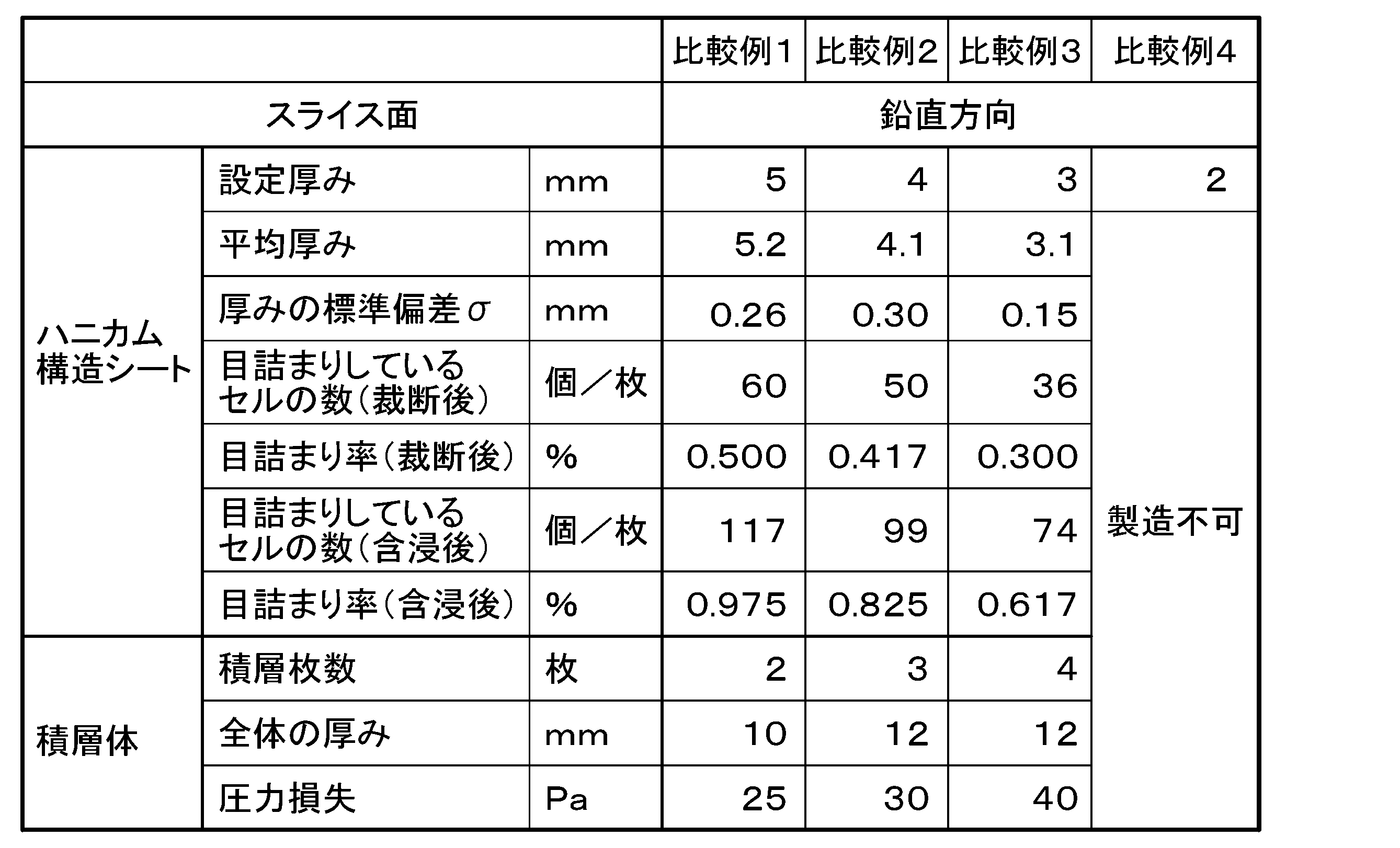
また、スライス面を垂直方向とした場合は、厚み3mmより薄いものを製造することが困難であることがわかった。
2 ハニカム構造シート
3 セル孔
4 シート基材
5 ライナー部材
6 コルゲート部材
7 接着剤
10 ハニカム構造体
11 残部構造体
20 ナイフユニット
21 バンドナイフ
30 移動テーブル
40 押さえロール
50 固定テーブル
60 案内板
100 スライサー
Claims (6)
- 複数のシート基材が互いに接着してなり、前記複数のシート基材により区画され、一方向に沿って貫通する多数のセル孔が形成されたハニカム構造体を、前記一方向と直交する面でスライスし、前記一方向が厚み方向となるハニカム構造シートを製造する方法であって、
前記ハニカム構造体を、前記一方向が鉛直方向となるように配置した状態で、水平方向に沿う面でスライスすることを特徴とする、ハニカム構造シートの製造方法。 - さらに、機能剤を含む液を塗布・含浸させる請求項1に記載のハニカム構造シートの製造方法。
- 請求項1又は2に記載のハニカム構造シートの製造方法で得られたハニカム構造シートを、複数積層する積層体の製造方法。
- 複数のシート基材が互いに接着してなり、前記複数のシート基材により区画され、厚み方向に沿って貫通する多数のセル孔が形成されたハニカム構造シートであって、
前記多数のセル孔が、254mm四方の面積あたり、2000~15000個形成されており、
厚みが1~20mmであり、
前記多数のセル孔の内、1/3以上の面積が閉塞しているセル孔の割合が0.1%以下である、ハニカム構造シート。 - 前記シート基材に機能剤が担持された、請求項4に記載のハニカム構造シート。
- 請求項4又は5に記載のハニカム構造シートが、複数積層した積層体。
Priority Applications (2)
| Application Number | Priority Date | Filing Date | Title |
|---|---|---|---|
| CN202380041675.8A CN119233891A (zh) | 2022-05-26 | 2023-05-24 | 蜂窝结构片和层叠体以及它们的制造方法 |
| KR1020247039589A KR20250007611A (ko) | 2022-05-26 | 2023-05-24 | 허니콤 구조 시트 및 적층체, 그리고 이들의 제조 방법 |
Applications Claiming Priority (2)
| Application Number | Priority Date | Filing Date | Title |
|---|---|---|---|
| JP2022-085774 | 2022-05-26 | ||
| JP2022085774A JP7819575B2 (ja) | 2022-05-26 | 2022-05-26 | ハニカム構造シート及び積層体の製造方法、並びに積層体 |
Publications (1)
| Publication Number | Publication Date |
|---|---|
| WO2023228963A1 true WO2023228963A1 (ja) | 2023-11-30 |
Family
ID=88919374
Family Applications (1)
| Application Number | Title | Priority Date | Filing Date |
|---|---|---|---|
| PCT/JP2023/019241 Ceased WO2023228963A1 (ja) | 2022-05-26 | 2023-05-24 | ハニカム構造シート及び積層体、並びにこれらの製造方法 |
Country Status (4)
| Country | Link |
|---|---|
| JP (1) | JP7819575B2 (ja) |
| KR (1) | KR20250007611A (ja) |
| CN (1) | CN119233891A (ja) |
| WO (1) | WO2023228963A1 (ja) |
Citations (3)
| Publication number | Priority date | Publication date | Assignee | Title |
|---|---|---|---|---|
| JPH079233A (ja) * | 1993-06-30 | 1995-01-13 | Fuji Heavy Ind Ltd | ハニカムコアの切削工具 |
| JP2007125466A (ja) * | 2005-11-01 | 2007-05-24 | Shiko Actec Kk | 厨房排気用脱臭フィルタ及び厨房排気用脱臭装置並びにその製造方法 |
| JP2008518818A (ja) * | 2004-11-03 | 2008-06-05 | ヤン ヘジュン | 曲面型のハニカム構造体とその製造方法 |
Family Cites Families (11)
| Publication number | Priority date | Publication date | Assignee | Title |
|---|---|---|---|---|
| US4677886A (en) * | 1985-12-12 | 1987-07-07 | Northrop Corporation | Honeycomb cutter and chip breaker/chaf remover |
| JP2684084B2 (ja) * | 1989-02-28 | 1997-12-03 | 昭和飛行機工業株式会社 | ハニカムコアの製造方法 |
| JPH048161A (ja) | 1990-04-25 | 1992-01-13 | Mitsubishi Electric Corp | 半導体装置 |
| JP2007068912A (ja) * | 2005-09-09 | 2007-03-22 | Azumi Roshi Kk | ハニカム形フィルタ |
| JP2007111310A (ja) * | 2005-10-21 | 2007-05-10 | Matsushita Electric Ind Co Ltd | 脱臭体 |
| JP2007330657A (ja) * | 2006-06-19 | 2007-12-27 | Toyobo Co Ltd | 脱臭ハニカム |
| CN102145498B (zh) * | 2011-04-21 | 2015-11-18 | 集美大学 | 一种冲切刀 |
| JP5956892B2 (ja) * | 2012-09-26 | 2016-07-27 | 住友化学株式会社 | 帯鋸の洗浄方法、グリーンハニカム成形体の切断方法及び切断装置 |
| KR101913269B1 (ko) * | 2016-12-29 | 2018-10-31 | 강릉원주대학교산학협력단 | 유무기 촉매를 코팅한 하니컴 탈취 필터 및 이의 제조방법 |
| JP6944833B2 (ja) * | 2017-08-03 | 2021-10-06 | イビデン株式会社 | ハニカム構造体の製造方法 |
| CN213829231U (zh) * | 2020-11-27 | 2021-07-30 | 合肥杰迈特汽车新材料有限公司 | 一种具有定位结构的蜂窝板切片机 |
-
2022
- 2022-05-26 JP JP2022085774A patent/JP7819575B2/ja active Active
-
2023
- 2023-05-24 WO PCT/JP2023/019241 patent/WO2023228963A1/ja not_active Ceased
- 2023-05-24 CN CN202380041675.8A patent/CN119233891A/zh active Pending
- 2023-05-24 KR KR1020247039589A patent/KR20250007611A/ko active Pending
Patent Citations (3)
| Publication number | Priority date | Publication date | Assignee | Title |
|---|---|---|---|---|
| JPH079233A (ja) * | 1993-06-30 | 1995-01-13 | Fuji Heavy Ind Ltd | ハニカムコアの切削工具 |
| JP2008518818A (ja) * | 2004-11-03 | 2008-06-05 | ヤン ヘジュン | 曲面型のハニカム構造体とその製造方法 |
| JP2007125466A (ja) * | 2005-11-01 | 2007-05-24 | Shiko Actec Kk | 厨房排気用脱臭フィルタ及び厨房排気用脱臭装置並びにその製造方法 |
Also Published As
| Publication number | Publication date |
|---|---|
| CN119233891A (zh) | 2024-12-31 |
| JP7819575B2 (ja) | 2026-02-25 |
| KR20250007611A (ko) | 2025-01-14 |
| JP2023173485A (ja) | 2023-12-07 |
Similar Documents
| Publication | Publication Date | Title |
|---|---|---|
| JP4643098B2 (ja) | チャネル流フィルタ | |
| US7824766B2 (en) | Sorption paper and method of producing sorption paper | |
| US4259092A (en) | Adsorptive material | |
| KR100429718B1 (ko) | 공기 필터 여과재, 그것을 사용한 공기 필터 팩과 공기필터 유닛, 및 공기 필터 여과재의 제조 방법 | |
| US20120168136A1 (en) | Total heat exchange element | |
| CN109982765A (zh) | 过滤器滤材、具有该过滤器滤材的过滤器元件以及过滤器滤材的制造方法 | |
| US6227383B1 (en) | Filtering material and process for the production thereof, and adsorption filter produced from said filtering material | |
| US20210316249A1 (en) | Membrane Device for Water and Energy Exchange | |
| JP2006223463A (ja) | エアフィルタ用シート及びその製造方法並びにエアフィルタ | |
| JP2014018722A (ja) | 除湿用フィルター素子 | |
| JP2013158668A (ja) | 除湿ローター用濾材 | |
| JP7819575B2 (ja) | ハニカム構造シート及び積層体の製造方法、並びに積層体 | |
| JP6115413B2 (ja) | フィルターエレメント | |
| JPS5935341B2 (ja) | 段ボ−ル | |
| JP2004314311A (ja) | 吸放湿性不織布構造体およびこれを用いた調湿剤 | |
| KR20050096845A (ko) | 케미컬 필터의 제조 방법 | |
| JP4819367B2 (ja) | エアフィルタ用シートの製造方法 | |
| JP2012170832A (ja) | コルゲートシート及び吸着素子 | |
| KR20240166016A (ko) | 흡착 필터, 흡착 로터 및 흡착 처리 장치 | |
| JP3074844B2 (ja) | 空気浄化用フィルタ | |
| JP2006095379A (ja) | フィルタユニットの製造方法 | |
| JP2000317243A (ja) | ケミカルフィルター | |
| JPS632645B2 (ja) | ||
| JPH0329751A (ja) | 脱酸素剤包装体 | |
| JP2010042345A (ja) | 除湿用フィルター素子 |
Legal Events
| Date | Code | Title | Description |
|---|---|---|---|
| 121 | Ep: the epo has been informed by wipo that ep was designated in this application |
Ref document number: 23811835 Country of ref document: EP Kind code of ref document: A1 |
|
| WWE | Wipo information: entry into national phase |
Ref document number: 202380041675.8 Country of ref document: CN |
|
| ENP | Entry into the national phase |
Ref document number: 20247039589 Country of ref document: KR Kind code of ref document: A |
|
| WWE | Wipo information: entry into national phase |
Ref document number: 1020247039589 Country of ref document: KR |
|
| NENP | Non-entry into the national phase |
Ref country code: DE |
|
| WWP | Wipo information: published in national office |
Ref document number: 202380041675.8 Country of ref document: CN |
|
| 122 | Ep: pct application non-entry in european phase |
Ref document number: 23811835 Country of ref document: EP Kind code of ref document: A1 |