WO2023223930A1 - ボールねじ装置およびその製造方法 - Google Patents
ボールねじ装置およびその製造方法 Download PDFInfo
- Publication number
- WO2023223930A1 WO2023223930A1 PCT/JP2023/017692 JP2023017692W WO2023223930A1 WO 2023223930 A1 WO2023223930 A1 WO 2023223930A1 JP 2023017692 W JP2023017692 W JP 2023017692W WO 2023223930 A1 WO2023223930 A1 WO 2023223930A1
- Authority
- WO
- WIPO (PCT)
- Prior art keywords
- axial direction
- ball screw
- shaft
- fitting
- caulking
- Prior art date
- Legal status (The legal status is an assumption and is not a legal conclusion. Google has not performed a legal analysis and makes no representation as to the accuracy of the status listed.)
- Ceased
Links
Images


Classifications
-
- F—MECHANICAL ENGINEERING; LIGHTING; HEATING; WEAPONS; BLASTING
- F16—ENGINEERING ELEMENTS AND UNITS; GENERAL MEASURES FOR PRODUCING AND MAINTAINING EFFECTIVE FUNCTIONING OF MACHINES OR INSTALLATIONS; THERMAL INSULATION IN GENERAL
- F16H—GEARING
- F16H25/00—Gearings comprising primarily only cams, cam-followers and screw-and-nut mechanisms
- F16H25/18—Gearings comprising primarily only cams, cam-followers and screw-and-nut mechanisms for conveying or interconverting oscillating or reciprocating motions
- F16H25/20—Screw mechanisms
- F16H25/22—Screw mechanisms with balls, rollers, or similar members between the co-operating parts; Elements essential to the use of such members
- F16H25/2204—Screw mechanisms with balls, rollers, or similar members between the co-operating parts; Elements essential to the use of such members with balls
- F16H25/2214—Screw mechanisms with balls, rollers, or similar members between the co-operating parts; Elements essential to the use of such members with balls with elements for guiding the circulating balls
- F16H25/2223—Cross over deflectors between adjacent thread turns, e.g. S-form deflectors connecting neighbouring threads
-
- F—MECHANICAL ENGINEERING; LIGHTING; HEATING; WEAPONS; BLASTING
- F16—ENGINEERING ELEMENTS AND UNITS; GENERAL MEASURES FOR PRODUCING AND MAINTAINING EFFECTIVE FUNCTIONING OF MACHINES OR INSTALLATIONS; THERMAL INSULATION IN GENERAL
- F16H—GEARING
- F16H25/00—Gearings comprising primarily only cams, cam-followers and screw-and-nut mechanisms
- F16H25/18—Gearings comprising primarily only cams, cam-followers and screw-and-nut mechanisms for conveying or interconverting oscillating or reciprocating motions
- F16H25/20—Screw mechanisms
- F16H25/22—Screw mechanisms with balls, rollers, or similar members between the co-operating parts; Elements essential to the use of such members
- F16H25/2204—Screw mechanisms with balls, rollers, or similar members between the co-operating parts; Elements essential to the use of such members with balls
-
- F—MECHANICAL ENGINEERING; LIGHTING; HEATING; WEAPONS; BLASTING
- F16—ENGINEERING ELEMENTS AND UNITS; GENERAL MEASURES FOR PRODUCING AND MAINTAINING EFFECTIVE FUNCTIONING OF MACHINES OR INSTALLATIONS; THERMAL INSULATION IN GENERAL
- F16D—COUPLINGS FOR TRANSMITTING ROTATION; CLUTCHES; BRAKES
- F16D1/00—Couplings for rigidly connecting two coaxial shafts or other movable machine elements
- F16D1/06—Couplings for rigidly connecting two coaxial shafts or other movable machine elements for attachment of a member on a shaft or on a shaft-end
-
- F—MECHANICAL ENGINEERING; LIGHTING; HEATING; WEAPONS; BLASTING
- F16—ENGINEERING ELEMENTS AND UNITS; GENERAL MEASURES FOR PRODUCING AND MAINTAINING EFFECTIVE FUNCTIONING OF MACHINES OR INSTALLATIONS; THERMAL INSULATION IN GENERAL
- F16D—COUPLINGS FOR TRANSMITTING ROTATION; CLUTCHES; BRAKES
- F16D1/00—Couplings for rigidly connecting two coaxial shafts or other movable machine elements
- F16D1/10—Quick-acting couplings in which the parts are connected by simply bringing them together axially
-
- F—MECHANICAL ENGINEERING; LIGHTING; HEATING; WEAPONS; BLASTING
- F16—ENGINEERING ELEMENTS AND UNITS; GENERAL MEASURES FOR PRODUCING AND MAINTAINING EFFECTIVE FUNCTIONING OF MACHINES OR INSTALLATIONS; THERMAL INSULATION IN GENERAL
- F16H—GEARING
- F16H25/00—Gearings comprising primarily only cams, cam-followers and screw-and-nut mechanisms
- F16H25/18—Gearings comprising primarily only cams, cam-followers and screw-and-nut mechanisms for conveying or interconverting oscillating or reciprocating motions
- F16H25/20—Screw mechanisms
- F16H25/22—Screw mechanisms with balls, rollers, or similar members between the co-operating parts; Elements essential to the use of such members
-
- F—MECHANICAL ENGINEERING; LIGHTING; HEATING; WEAPONS; BLASTING
- F16—ENGINEERING ELEMENTS AND UNITS; GENERAL MEASURES FOR PRODUCING AND MAINTAINING EFFECTIVE FUNCTIONING OF MACHINES OR INSTALLATIONS; THERMAL INSULATION IN GENERAL
- F16H—GEARING
- F16H25/00—Gearings comprising primarily only cams, cam-followers and screw-and-nut mechanisms
- F16H25/18—Gearings comprising primarily only cams, cam-followers and screw-and-nut mechanisms for conveying or interconverting oscillating or reciprocating motions
- F16H25/20—Screw mechanisms
- F16H25/24—Elements essential to such mechanisms, e.g. screws, nuts
-
- H—ELECTRICITY
- H02—GENERATION; CONVERSION OR DISTRIBUTION OF ELECTRIC POWER
- H02K—DYNAMO-ELECTRIC MACHINES
- H02K7/00—Arrangements for handling mechanical energy structurally associated with dynamo-electric machines, e.g. structural association with mechanical driving motors or auxiliary dynamo-electric machines
- H02K7/06—Means for converting reciprocating motion into rotary motion or vice versa
-
- F—MECHANICAL ENGINEERING; LIGHTING; HEATING; WEAPONS; BLASTING
- F16—ENGINEERING ELEMENTS AND UNITS; GENERAL MEASURES FOR PRODUCING AND MAINTAINING EFFECTIVE FUNCTIONING OF MACHINES OR INSTALLATIONS; THERMAL INSULATION IN GENERAL
- F16D—COUPLINGS FOR TRANSMITTING ROTATION; CLUTCHES; BRAKES
- F16D1/00—Couplings for rigidly connecting two coaxial shafts or other movable machine elements
- F16D1/10—Quick-acting couplings in which the parts are connected by simply bringing them together axially
- F16D2001/103—Quick-acting couplings in which the parts are connected by simply bringing them together axially the torque is transmitted via splined connections
-
- F—MECHANICAL ENGINEERING; LIGHTING; HEATING; WEAPONS; BLASTING
- F16—ENGINEERING ELEMENTS AND UNITS; GENERAL MEASURES FOR PRODUCING AND MAINTAINING EFFECTIVE FUNCTIONING OF MACHINES OR INSTALLATIONS; THERMAL INSULATION IN GENERAL
- F16H—GEARING
- F16H25/00—Gearings comprising primarily only cams, cam-followers and screw-and-nut mechanisms
- F16H25/18—Gearings comprising primarily only cams, cam-followers and screw-and-nut mechanisms for conveying or interconverting oscillating or reciprocating motions
- F16H25/20—Screw mechanisms
- F16H2025/204—Axial sliding means, i.e. for rotary support and axial guiding of nut or screw shaft
-
- F—MECHANICAL ENGINEERING; LIGHTING; HEATING; WEAPONS; BLASTING
- F16—ENGINEERING ELEMENTS AND UNITS; GENERAL MEASURES FOR PRODUCING AND MAINTAINING EFFECTIVE FUNCTIONING OF MACHINES OR INSTALLATIONS; THERMAL INSULATION IN GENERAL
- F16H—GEARING
- F16H25/00—Gearings comprising primarily only cams, cam-followers and screw-and-nut mechanisms
- F16H25/18—Gearings comprising primarily only cams, cam-followers and screw-and-nut mechanisms for conveying or interconverting oscillating or reciprocating motions
- F16H25/20—Screw mechanisms
- F16H2025/2062—Arrangements for driving the actuator
- F16H2025/2075—Coaxial drive motors
-
- F—MECHANICAL ENGINEERING; LIGHTING; HEATING; WEAPONS; BLASTING
- F16—ENGINEERING ELEMENTS AND UNITS; GENERAL MEASURES FOR PRODUCING AND MAINTAINING EFFECTIVE FUNCTIONING OF MACHINES OR INSTALLATIONS; THERMAL INSULATION IN GENERAL
- F16H—GEARING
- F16H25/00—Gearings comprising primarily only cams, cam-followers and screw-and-nut mechanisms
- F16H25/18—Gearings comprising primarily only cams, cam-followers and screw-and-nut mechanisms for conveying or interconverting oscillating or reciprocating motions
- F16H25/20—Screw mechanisms
- F16H2025/2062—Arrangements for driving the actuator
- F16H2025/2087—Arrangements for driving the actuator using planetary gears
-
- F—MECHANICAL ENGINEERING; LIGHTING; HEATING; WEAPONS; BLASTING
- F16—ENGINEERING ELEMENTS AND UNITS; GENERAL MEASURES FOR PRODUCING AND MAINTAINING EFFECTIVE FUNCTIONING OF MACHINES OR INSTALLATIONS; THERMAL INSULATION IN GENERAL
- F16H—GEARING
- F16H25/00—Gearings comprising primarily only cams, cam-followers and screw-and-nut mechanisms
- F16H25/18—Gearings comprising primarily only cams, cam-followers and screw-and-nut mechanisms for conveying or interconverting oscillating or reciprocating motions
- F16H25/20—Screw mechanisms
- F16H25/24—Elements essential to such mechanisms, e.g. screws, nuts
- F16H2025/2481—Special features for facilitating the manufacturing of spindles, nuts, or sleeves of screw devices
Definitions
- the present disclosure relates to a ball screw device and a manufacturing method thereof.
- ball screw devices Because a ball screw device causes the balls to roll between the screw shaft and the nut, higher efficiency can be obtained compared to a sliding screw device that brings the screw shaft and nut into direct contact. For this reason, ball screw devices are used in various mechanical devices such as electric brake devices of automobiles, automatic manual transmissions (AMT), and positioning devices of machine tools in order to convert the rotational motion of a drive source such as an electric motor into linear motion. It has been incorporated.
- a ball screw device consists of a screw shaft having a spiral shaft-side ball screw groove on the outer peripheral surface, a nut having a spiral nut-side ball screw groove on the inner peripheral surface, and a shaft-side ball screw groove and a nut-side ball screw groove. and a plurality of balls arranged between.
- a ball screw device one of the screw shaft and the nut functions as a rotary motion element, and the other functions as a linear motion element, depending on the application.
- FIG. 23 shows a ball screw device 100 with a conventional structure, which is described in Japanese Patent Application Laid-Open No. 2009-286137.
- the screw shaft 101 of the ball screw device 100 has a threaded portion 103 and a fitting shaft portion 104 arranged on one side of the threaded portion 103 in the axial direction.
- a shaft-side ball screw groove 105 is formed on the outer peripheral surface of the threaded portion 103.
- the fitting shaft portion 104 has a smaller outer diameter than the threaded portion 103.
- the screw shaft 101 is arranged coaxially with the nut 102 with the threaded portion 103 inserted inside the nut 102.
- a nut-side ball screw groove (not shown) is formed on the inner peripheral surface of the nut 102.
- the nut 102 engages with a plurality of guide rods 107 supported by the housing 106 to prevent rotation thereof.
- the shaft-side ball screw groove 105 and the nut-side ball screw groove are arranged to face each other in the radial direction, and form a helical load path.
- the starting point and ending point of the load path are connected by a circulation means (not shown).
- the balls that have reached the end of the load path are returned to the start of the load path through the circulation means.
- the starting point and ending point of the load path are switched depending on the direction of relative displacement (relative rotation direction) between the screw shaft 101 and the nut 102 in the axial direction.
- the rotation of the electric motor 108 which is a drive source, is decelerated by a pulley device 109 and transmitted to the screw shaft 101 via the fitting shaft portion 104. Therefore, the driven pulley 110 is fitted onto the fitting shaft portion 104 in a relatively non-rotatable manner, and the drive pulley 112 is fitted on the tip of the motor shaft 111 of the electric motor 108 in a relatively non-rotatable manner.
- a belt 113 is stretched between the driven pulley 110 and the driven pulley 110.
- Measures are taken to prevent the mating shaft portion of the screw shaft from slipping out in the axial direction from a mating member such as a pulley or gear for rotationally driving the screw shaft, which is fitted onto the mating shaft portion. Be taken. As such a measure, it has been considered to form a caulking portion at the tip of the fitting shaft portion.
- a pullout force not only acts on the screw shaft or the fitting member in a direction parallel to the central axis, but also acts on the screw shaft or the fitting member in a direction perpendicular to the central axis.
- Circumferential moments may act. When such a moment acts, the central axis of the mating shaft section and the central axis of the mating member are tilted, and simply forming a caulked portion may cause the mating shaft section to come out of the mating member in the axial direction.
- the present disclosure can effectively prevent the fitting shaft portion of the screw shaft from coming out of the fitting member in the axial direction even when a moment about an axis perpendicular to the central axis acts on the screw shaft or the fitting member.
- the purpose is to provide a ball screw device.
- a ball screw device includes a screw shaft, a nut, a plurality of balls, and a fitting member.
- the screw shaft has a threaded portion having a helical shaft-side ball screw groove on the outer peripheral surface, and a fitting shaft portion disposed on one side of the threaded portion in the axial direction.
- the nut has a spiral nut-side ball screw groove on the inner peripheral surface.
- the plurality of balls are arranged between the shaft-side ball screw groove and the nut-side ball screw groove.
- the fitting member is externally fitted onto the fitting shaft portion so as not to rotate relative to the fitting shaft portion.
- the fitting shaft portion has an inner diameter side engagement portion on the outer circumferential surface in which a plurality of external teeth are arranged in the circumferential direction.
- the fitting member has a plurality of internal teeth arranged in the circumferential direction on the inner circumferential surface, and an outer engagement portion that engages with the inner engagement portion.
- the engagement portion between the inner diameter side engagement portion and the outer diameter side engagement portion includes a portion having a radial interference in a portion in the axial direction.
- the fitting shaft portion has a caulking portion at the one end in the axial direction that engages with the fitting member in the axial direction.
- the fitting shaft portion includes a center hole that is open at the end surface on the one side in the axial direction, and a cylindrical portion that exists outside the center hole in the radial direction.
- the caulking portion is provided at the end of the cylindrical portion on the one side in the axial direction, and can be pressed against the side surface of the fitting member on the one side in the axial direction.
- the center hole may have a bottom surface facing the one side in the axial direction.
- the outer peripheral surface of the cylindrical portion can be pressed against the inner peripheral surface of the fitting member.
- the caulking portion may be inclined in a direction toward the one side in the axial direction as it goes toward the outer side in the radial direction.
- the caulking portion may be provided around the entire circumference of the end portion of the one side in the axial direction of the fitting shaft portion.
- the caulking portion has a continuous annular shape in the circumferential direction.
- the caulking portion can also be constituted by a plurality of caulking portions arranged at a plurality of locations in the circumferential direction at the end portion of the one axial side of the fitting shaft portion. In this case, it is preferable that the plurality of caulking parts are arranged at equal intervals.
- the caulking portion is provided at the one end in the axial direction of at least one external tooth of the plurality of external teeth, and the caulking portion is provided at the end of the one side in the axial direction of at least one of the plurality of external teeth,
- the inner circumferential edge portion on the one side in the axial direction can be engaged with the inner peripheral edge portion in the axial direction.
- the caulking portion may be constituted by a plurality of caulking portions arranged at a plurality of locations in the circumferential direction.
- the plurality of caulking portions are arranged at equal intervals in the circumferential direction.
- the caulking portion may be constituted by one caulking portion.
- the portion having the radial interference may be disposed at a position away from the caulking portion of the engaging portion toward the other side in the axial direction. can.
- the portion having the interference in the radial direction may be arranged at a position separated from the caulking portion toward the other side in the axial direction.
- the portion having the interference in the radial direction may be arranged at a position adjacent to the other side of the caulking portion in the axial direction.
- the plurality of external teeth have a root diameter larger than the root diameter of other parts, or a tip diameter of the plurality of external teeth is larger than a tooth bottom diameter of the other parts. It may have a portion in the axial direction that is larger than the diameter of the tip.
- the plurality of internal teeth have a root diameter smaller than the root diameter of other parts, or a tip diameter of the plurality of internal teeth is smaller than a tooth bottom diameter of the other parts. It may have a portion in the axial direction that is smaller than the diameter of the tip.
- the fitting member may have a symmetrical shape with respect to the axial direction.
- the fitting member may be configured by a driving member for rotationally driving the screw shaft.
- the driving member can be composed of a carrier, a gear, a motor output shaft, a pulley, or a sprocket that constitute the planetary reduction mechanism.
- the fitting member may include a stopper that engages with the nut in the circumferential direction and prevents relative rotation between the nut and the screw shaft.
- the fitting member may be constituted by a rotation preventing member that prevents rotation of the screw shaft.
- a method for manufacturing a ball screw device relates to a method for manufacturing a ball screw device in which the caulking portion is provided at the one end in the axial direction of the cylindrical portion.
- the method for manufacturing the ball screw device includes: It has a threaded part having a spiral shaft-side ball screw groove on the outer peripheral surface, and a blank fitting shaft part disposed on one side in the axial direction of the threaded part, and the blank fitting shaft part has a spiral shaft side ball screw groove on the outer peripheral surface. is provided with an inner radial side engaging portion in which a plurality of external teeth are arranged in the circumferential direction, an element center hole opening at the end face on the one side in the axial direction, and an element center hole located outside the element center hole in the radial direction.
- a plurality of internal teeth are provided on the inner circumferential surface of the plain fitting shaft portion of the plain threaded shaft having a plain cylindrical portion, and a plurality of internal teeth are arranged in the circumferential direction, and the inner diameter side engagement externally fitting a fitting member having an outer diameter side engaging portion that engages with the portion; moving a caulking jig relative to the other side in the axial direction with respect to the plain threaded shaft, and pressing a machined surface provided on an outer circumferential surface of the caulking jig against an inner circumferential surface of the plain cylindrical part; and plastically deforming the bare cylindrical portion toward the outer side in the radial direction to form a caulked portion.
- the machined surface is constituted by a plurality of conical machined surfaces whose generatrix lines have different inclination angles with respect to the central axis of the caulking jig.
- the plurality of processed surfaces include a first processed surface provided at the other end in the axial direction of the outer peripheral surface of the caulking jig, and a first processed surface of the outer peripheral surface of the caulked part. and a second machined surface provided on the one side in the axial direction rather than the surface.
- the angle of inclination of the generatrix of the second machined surface with respect to the central axis is greater than the angle of inclination of the generatrix of the first machined surface with respect to the central axis.
- the first processed surface and the second processed surface may be connected via a corner R portion or a relief groove portion.
- the caulking jig may be moved relative to the other side in the axial direction with respect to the screw shaft until the end surface of the other side in the axial direction of the caulking jig abuts the bottom surface of the element center hole. can.
- the caulking portion is provided at the end of the one side in the axial direction of at least one external tooth of the plurality of external teeth.
- the present invention relates to a method of manufacturing a screw device.
- the method for manufacturing the ball screw device includes: It has a threaded part having a spiral shaft-side ball screw groove on the outer peripheral surface, and a blank fitting shaft part disposed on one side in the axial direction of the threaded part, and the blank fitting shaft part has a spiral shaft side ball screw groove on the outer peripheral surface.
- a plurality of screw holes are provided on the inner circumferential surface of the screw shaft, and the screw shaft is provided with an inner diameter side engagement portion in which a plurality of outer teeth are arranged in the circumferential direction.
- the caulking jig is relatively displaced to the other side in the axial direction with respect to the plain thread shaft, and the machining surface provided on the caulking jig is turned to the outer side of at least one of the plurality of outer teeth.
- the fitting shaft portion of the screw shaft moves from the fitting member to the axis. It is possible to effectively prevent the object from slipping out in the direction.
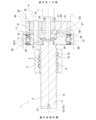
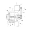
- FIG. 1 is a sectional view showing a structure in which a planetary reduction mechanism is combined with a ball screw device of a first example of an embodiment of the present disclosure.
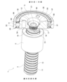
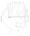
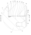
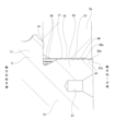
- FIG. 2 is a partially cutaway perspective view of the first example of the ball screw device, viewed from the outside in the radial direction and one side in the axial direction.
- FIG. 3 is a partially cutaway perspective view of the ball screw device of the first example, as seen from the outside in the radial direction and the other side in the axial direction.
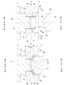
- FIG. 4 is a partially enlarged view of FIG.
- FIG. 5(A) and 5(B) show a ball screw device of a first example in which a caulking jig is used to attach a caulking portion to the one end in the axial direction of the fitting shaft portion of the screw shaft.
- FIG. FIG. 6 is a diagram corresponding to FIG. 5(A) when a caulking part is formed using another example of a caulking jig in the ball screw device of the first example.
- 7(A) and FIG. 7(B) are diagrams corresponding to FIG. 5(A) and FIG. 5(B) regarding a second example of the embodiment of the present disclosure.
- 8(A) and FIG. 8(B) are diagrams corresponding to FIG. 5(A) and FIG. 5(B) regarding a modification of the second example.
- FIG. 9(A) and FIG. 9(B) are diagrams corresponding to FIG. 5(A) and FIG. 5(B) regarding a third example of the embodiment of the present disclosure.
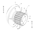
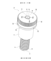
- FIG. 10 is a perspective view of a fourth example of a ball screw device according to an embodiment of the present disclosure.
- FIG. 11 is a diagram corresponding to FIG. 4 regarding the fourth example.
- FIG. 12 is a partially enlarged end view of the fitting portion between the fitting shaft portion of the screw shaft and the mounting hole of the carrier, as viewed from one side in the axial direction, in the fourth example.
- FIG. 13 is a partially enlarged perspective view showing the screw shaft taken out from the ball screw device of the fourth example.
- FIG. 14(A) to 14(D) show a ball screw device according to a fourth example, in which a caulking jig is used to attach a caulking portion to the one end in the axial direction of the fitting shaft portion of the screw shaft.
- FIG. FIG. 15 is a diagram corresponding to FIG. 4 regarding the fifth example of the embodiment of the present disclosure.
- FIG. 16 is a diagram corresponding to FIG. 4 regarding the sixth example of the embodiment of the present disclosure.
- FIG. 17 is a diagram corresponding to FIG. 4 regarding the seventh example of the embodiment of the present disclosure.
- FIG. 18 is a diagram corresponding to FIG. 4 regarding the eighth example of the embodiment of the present disclosure.
- FIG. 19 is a diagram corresponding to FIG. 4 regarding the ninth example of the embodiment of the present disclosure.
- FIG. 15 is a diagram corresponding to FIG. 4 regarding the fifth example of the embodiment of the present disclosure.
- FIG. 16 is a diagram corresponding to FIG. 4 regarding the sixth example of the embodiment of the present disclosure
- FIG. 20 is a sectional view of a ball screw device according to a tenth example of the embodiment of the present disclosure.
- FIG. 21 is a diagram corresponding to FIG. 10 for the tenth example.
- FIG. 22 is a diagram corresponding to FIG. 4 regarding the tenth example.
- FIG. 23 is a sectional view showing a structure in which a conventional ball screw device and a pulley device are combined.
- the ball screw device 1 of this example is used for, but not limited to, applications such as operating a piston of a hydraulic cylinder in an electric brake booster device, for example.
- the ball screw device 1 includes a screw shaft 2, a nut 3, a plurality of balls 4, and a fitting member 5.
- the screw shaft 2 is a rotary movement element that is rotationally driven by an electric motor 7, which is a drive source, via a planetary reduction mechanism 8, and rotates during use.
- the screw shaft 2 is inserted into the inside of the nut 3 and is arranged coaxially with the nut 3.
- the nut 3 is prevented from rotating with respect to the screw shaft 2 by a rotation prevention mechanism (not shown), and is a linear motion element that moves linearly during use.
- a spiral load path 9 is provided between the outer peripheral surface of the screw shaft 2 and the inner peripheral surface of the nut 3.
- a plurality of balls 4 are arranged in the load path 9 so as to be able to roll.
- the axial direction, radial direction, and circumferential direction refer to the axial direction, radial direction, and circumferential direction regarding the screw shaft 2 unless otherwise specified. Further, one axial side refers to the right side in FIGS. 1 to 5, and the other axial side refers to the left side in FIGS. 1 to 5.
- the screw shaft 2 is made of metal and has a threaded portion 11 and a fitting shaft portion 12 disposed on one side of the threaded portion 11 in the axial direction.
- the threaded portion 11 and the fitting shaft portion 12 are arranged coaxially and are integrally formed with each other.
- the fitting shaft portion 12 has a smaller outer diameter than the threaded portion 11.
- the threaded portion 11 has a spiral shaft-side ball screw groove 13 on its outer peripheral surface.
- the shaft-side ball screw groove 13 is formed by grinding, cutting, rolling, or the like on the outer circumferential surface of the threaded portion 11 .
- the number of threads of the shaft-side ball screw groove 13 is one, and the groove shape (groove bottom shape) of the cross section of the shaft-side ball screw groove 13 is constituted by a Gothic arch or a circular arc.
- the threaded portion 11 has a ring-shaped abutment surface 14 on one end surface in the axial direction.
- the abutment surface 14 is a flat surface that exists on a virtual plane orthogonal to the central axis of the screw shaft 2.
- the threaded portion 11 has a bottomed first center hole 15 in the radial center of the other end surface in the axial direction.
- the fitting shaft portion 12 has an axial dimension that is slightly larger than the axial dimension of the small diameter hole portion 54 of the attachment hole 26 provided in the fitting member 5.
- the fitting shaft portion 12 has an inner diameter side engagement portion 16 on the outer peripheral surface.
- a plurality of external teeth 17 are arranged in the circumferential direction of the inner engagement portion 16 .
- the plurality of external teeth 17 extend in the entire axial direction of the inner diameter side engaging portion 16, and the inner diameter side engaging portion 16 extends in the entire axial direction of the fitting shaft portion 12.
- the plurality of external teeth 17 are arranged at equal intervals in the circumferential direction of the inner engagement portion 16. That is, the radially inner engaging portion 16 is constituted by a male spline.
- the plurality of external teeth 17 are coaxial with the shaft-side ball screw groove 13 of the threaded portion 11 .
- each of the plurality of external teeth 17 is composed of an involute spline tooth, but it can also be composed of an angular spline tooth.
- the plurality of external teeth 17 are spline-processed based on the outer diameter of the threaded portion 11, so that the center of the pitch circle of the plurality of external teeth 17, which is a drive torque transmission portion, and the rotation-to-linear conversion portion
- the coaxiality of the shaft-side ball screw groove 13 with the central axis is improved.
- the tip diameters of the plurality of external teeth 17 are constant in the axial direction.
- the root diameters of the plurality of external teeth 17 are The diameter of the tooth root at the end on the other side in the axial direction, which is a part in the axial direction of the plurality of external teeth 17, is not constant over the axial direction, and It is slightly larger than the diameter of the root circle at the other side.
- a protuberance 19 that is slightly raised toward the outside in the radial direction is provided at the other end in the axial direction of the bottom portion 18 of the plurality of external teeth 17 .
- the raised portion 19 has a trapezoidal cross-sectional shape with respect to a virtual plane containing the central axis O2 of the screw shaft 2.
- the raised portion 19 consists of inclined surfaces arranged on both sides in the axial direction and a flat surface arranged in the middle part in the axial direction.
- the axial dimension of the raised portion 19 is preferably about 1/50 to 1/2 times the axial dimension (total length) of the plurality of external teeth 17. In this example, it is approximately 1/5 times as large.
- the fitting shaft portion 12 has a bottomed second center hole 21 that is a center hole in the radial center of one end surface in the axial direction.
- the second center hole 21 has a bottom surface (back end surface) facing one side in the axial direction.
- the second center hole 21 and the first center hole 15 provided in the threaded portion 11 are arranged coaxially with each other.
- the bottom surface of the second center hole 21 is located in the axially intermediate portion of the fitting shaft portion 12 and has a concave conical shape.
- the second center hole 21 has an inner diameter larger than the first center hole 15, and is 1/2 to 4 times the outer diameter of the portion of the fitting shaft portion 12 that is axially removed from the caulking portion 32. /5 times the inner diameter.
- the screw shaft 2 is arranged coaxially with the nut 3 with the threaded portion 11 inserted inside the nut 3.
- the screw shaft may include, in addition to the threaded portion 11 and the fitting shaft portion 12, a support shaft portion (second fitting shaft portion) for externally fitting and fixing other members. can.
- the nut 3 is made of metal and has a cylindrical shape as a whole.
- the nut 3 has a spiral nut-side ball screw groove 22 on its inner peripheral surface.
- the nut 3 further has a circulation groove 10.
- the nut-side ball screw groove 22 has a helical shape and is formed on the inner peripheral surface of the nut 3 by, for example, grinding, cutting, rolling tapping, cutting tapping, etc.
- the number of nut-side ball screw grooves 22 is one, similar to the shaft-side ball screw groove 13.
- the cross-sectional groove shape of the nut-side ball screw groove 22 is also constituted by a Gothic arch or a circular arc.
- the nut side ball screw groove 22 has the same lead as the shaft side ball screw groove 13. With the threaded portion 11 of the screw shaft 2 inserted into the nut 3, the shaft-side ball screw groove 13 and the nut-side ball screw groove 22 are arranged to face each other in the radial direction, so that the load path 9 is configured.
- the circulation groove 10 has a substantially S-shape and is formed on the inner peripheral surface of the nut 3 by, for example, forging (cold forging).
- the circulation groove 10 smoothly connects axially adjacent portions of the nut-side ball screw groove 22 and connects the starting point and ending point of the load path 9.
- the balls 4 that have reached the end point of the load path 9 are returned to the starting point of the load path 9 through the circulation groove 10.
- the starting point and ending point of the load path 9 are switched depending on the direction of relative displacement between the screw shaft 2 and the nut 3 in the axial direction (relative rotation direction).
- the circulation groove 10 has a substantially semicircular cross-sectional shape.
- the circulation groove 10 has a groove width slightly larger than the diameter of the ball 4, and has a groove depth that allows the ball 4 moving in the circulation groove 10 to get over the thread of the shaft-side ball screw groove 13.
- the nut 3 since the nut 3 is used as a linear motion element, the nut 3 is prevented from rotating with respect to the screw shaft 2 by a rotation prevention mechanism (not shown).
- a rotation prevention mechanism (not shown).
- various conventionally known structures can be employed as the nut rotation prevention mechanism.
- a structure may be adopted in which a protrusion (key) provided on the inner circumferential surface of a fixing member such as the housing 24 is engaged with a groove formed in the outer circumferential surface of the nut 3 in the axial direction.
- a fitting cylinder such as a piston (not shown) can be externally fitted and fixed to the small diameter portion.
- the plurality of balls 4 are rotatably arranged in the load path 9 and the circulation groove 10.
- Each of the plurality of balls 4 is made of a steel ball having a predetermined diameter.
- the balls 4 placed in the load path 9 roll while receiving a compressive load.
- the balls 4 arranged in the circulation groove 10 are pushed by the following balls 4 and roll without being subjected to compressive loads.
- the fitting member 5 is externally fitted onto the fitting shaft portion 12 such that it cannot rotate relative to the fitting shaft portion 12 .
- the fitting member 5 has a circular flat plate shape, and has a mounting hole 26 extending in the axial direction in the radially central portion.
- the attachment hole 26 has an engagement portion 27 on the outer diameter side.
- a plurality of internal teeth 28 are arranged in the circumferential direction on the inner circumferential surface of the outer diameter side engaging portion 27 .
- the plurality of internal teeth 28 extend in the entire axial direction of the outer diameter side engaging portion 27, and the outer diameter side engaging portion 27 extends in the entire axial direction of the mounting hole 26 of the fitting member 5. ing.
- the plurality of internal teeth 28 are arranged at equal intervals in the circumferential direction of the outer diameter side engaging portion 27. That is, the outer diameter side engaging portion 27 is constituted by a female spline.
- each of the plurality of internal teeth 28 is composed of an involute spline tooth, but it can also be composed of an angular spline tooth.
- the root diameter and tip diameter of the plurality of internal teeth 28 are constant in the axial direction.
- the mounting hole 26 is configured as a stepped hole, with a small diameter hole 54 provided in the other half in the axial direction, and a small diameter hole 54 provided in the half in the one axial direction. It has a large diameter hole portion 55 having an inner diameter larger than the inner diameter of.
- the outer diameter side engaging portion 27 is provided over the entire axial direction of the inner circumferential surface of the small diameter hole portion 54.
- the large diameter hole 55 has a cylindrical inner peripheral surface.
- the inner diameter of the large diameter hole 55 is the same as the outer diameter of the threaded portion 11 or slightly smaller than the outer diameter of the threaded portion 11 .
- the large diameter hole portion 55 and the small diameter hole portion 54 are connected in the radial direction by a circular step surface 56 facing one side in the axial direction.
- the stepped surface 56 is a flat surface perpendicular to the central axis O5 of the fitting member 5, and constitutes a radially inner side of one side surface of the fitting member 5 in the axial direction.
- the fitting member 5 has an asymmetric shape with respect to the axial direction.
- the fitting member can also have a symmetrical shape with respect to the axial direction. In this case, large diameter holes are provided on both sides of the mounting hole in the axial direction.
- An inner ring raceway 29 constituting the rolling bearing 6 is directly formed in the axially intermediate portion (the central portion in the illustrated example) of the outer circumferential surface of the fitting member 5 . That is, in this example, the fitting member 5 also functions as an inner ring forming the rolling bearing 6, and the inner ring forming the rolling bearing 6 is omitted.
- the rolling bearing 6 is constituted by a deep groove ball bearing capable of supporting radial loads and axial loads in both directions
- the inner ring raceway 29 is of a deep groove type, and its cross-sectional shape is a concave arc shape. .
- induction hardening and tempering are performed only on the outer peripheral surface of the fitting member 5 on which the inner raceway 29 is formed, to form a heat-treated hardened layer.
- No heat-treated hardened layer is formed on one side surface in the axial direction and the other side surface in the axial direction of the fitting member 5.
- a seal groove is formed over the entire circumference of the outer circumferential surface of the fitting member 5 at a portion that deviates from the inner ring raceway 29 on both sides in the axial direction.
- the parts are in sliding contact.
- both axially opposite portions of the outer circumferential surface of the fitting member 5 can also be configured in a partially cylindrical shape.
- the fitting member 5 has a plurality of support holes 30 for inserting and supporting pinion pins 41 forming the planetary speed reduction mechanism 8 at a plurality of locations (three locations in the illustrated example) in the circumferential direction of the radially intermediate portion.
- the plurality of support holes 30 are arranged at equal intervals in the circumferential direction. Further, the respective central axes of the plurality of support holes 30 are arranged parallel to each other.
- the support hole 30 is constituted by a through hole passing through the fitting member 5 in the axial direction, and is open on both sides of the fitting member 5 in the axial direction.
- the support hole 30 can also be configured as a bottomed hole that opens only on one side surface of the fitting member 5 in the axial direction.
- each of the plurality of support holes 30 is constant in the axial direction.
- the diameter of an imaginary circle passing through the radially inner ends of the plurality of support holes 30 is slightly larger than the inner diameter of the nut 3.
- the diameter of the virtual circle passing through the radially outer ends of the plurality of support holes 30 is slightly larger than the outer diameter of the nut 3.
- One side surface of the fitting member 5 in the axial direction is constituted by a stepped surface.
- an outer diameter side surface 57 located on the outside in the radial direction than the step surface 56 is parallel to the step surface 56 and on one side in the axial direction than the step surface 56. placed on the side.
- the other axial side surface of the fitting member 5 is constituted by a flat surface that exists on a virtual plane orthogonal to the central axis O5 of the fitting member 5.
- the fitting member 5 is externally fitted onto the fitting shaft portion 12 by inserting the fitting shaft portion 12 that constitutes the screw shaft 2 inside the mounting hole 26 .
- the fitting shaft portion 12 that constitutes the screw shaft 2 inside the mounting hole 26 .
- the outer diameter side engagement portion 27 of the fitting member 5 engages with the inner diameter side engagement portion 16 of the fitting shaft portion 12 so as not to be relatively rotatable.
- the plurality of internal teeth 28 of the outer engagement portion 27, which are female spline teeth, spline engage with the outer teeth 17 of the inner engagement portion 16, which are male spline teeth.
- the tip circle diameters of the plurality of internal teeth 28 of the outer diameter side engagement part 27 are constant in the axial direction, whereas the plurality of outer teeth 17 of the inner diameter side engagement part 16 are , has a raised portion 19 of the root portion 18, which is a portion in the axial direction whose root diameter is larger than the root diameter of the other portion.
- the root diameter at the other end in the axial direction of the plurality of external teeth 17 of the inner diameter side engagement portion 16 is smaller than the tip diameter of the plurality of internal teeth 28 of the outer diameter side engagement portion 27.
- the diameter of the bottom circle of the plurality of external teeth 17 of the inner diameter side engagement portion 16 at a portion from one end in the axial direction to the other end in the axial direction is slightly larger than that of the plurality of outer teeth 17 of the inner diameter side engagement portion 16. It is slightly smaller than the tip circle diameter of the internal teeth 28.
- the other end in the axial direction of the engagement portion between the inner diameter side engagement portion 16 and the outer diameter side engagement portion 27 becomes a press-fit portion 31 having an interference in the radial direction. That is, the press-fitting portion 31, which is a portion having a tightening margin in the radial direction, is located at one end in the axial direction of the fitting shaft portion 12 among the inner diameter side engagement portion 16, the outer diameter side engagement portion 27, and the engagement portion. It is disposed at a portion away from the caulking portion 32 formed on the other side in the axial direction.
- the press-fitting portion 31 is arranged at a portion of the engagement portion between the inner diameter side engagement portion 16 and the outer diameter side engagement portion 27 that is spaced apart from the caulking portion 32 toward the other side in the axial direction.
- a portion of the engagement portion between the inner diameter side engagement portion 16 and the outer diameter side engagement portion 27 from one end in the axial direction to the other end in the axial direction is a clearance fit with a slight gap in the radial direction.
- the inner diameter side engagement part 16 and the outer diameter side engagement part 27 are provided with a press-fitting part 31, which is a part having a tightening margin in the radial direction, in a part of the axial direction, so that the screw shaft 2 The fitting shaft portion 12 is prevented from slipping out from the fitting member 5 in the axial direction.
- the fitting shaft 12 in order to effectively prevent the fitting shaft 12 from slipping out from the mounting hole 26 to the other side in the axial direction, the fitting shaft 12 is inserted into the mounting hole 26 and the fitting shaft 12 is , has a caulking portion 32 at one end in the axial direction that engages with the fitting member 5 in the axial direction.
- the caulking part 32 is provided at one end in the axial direction of the cylindrical part 53 that exists on the radially outer side of the second center hole 21 in the fitting shaft part 12, and is pressed against one side in the axial direction.
- the caulking portion 32 is formed at one end of the fitting shaft portion 12 in the axial direction over the entire circumference. That is, the caulking portion 32 is configured in a circular ring shape that is continuous in the circumferential direction.
- the caulking portion 32 has a substantially conical cylindrical shape that is inclined toward one side in the axial direction as it goes radially outward.
- the caulking portion 32 is arranged inside the large diameter hole portion 55 provided in the fitting member 5.
- the other axial side surface of the caulked portion 32 is pressed against the stepped surface 56 .
- the stepped surface 56 constitutes one axial side surface of the fitting member 5 against which the caulking portion 32 is pressed.
- the caulking portion 32 is arranged on the other axial side of the outer diameter side surface 57 that constitutes one axial side surface of the fitting member 5 . This prevents the caulking portion 32 from interfering with other members such as the sun gear 38 and the planetary gears 39 that constitute the planetary speed reduction mechanism 8 .
- a gap is provided between the radially outer end of the caulked portion 32 and the inner peripheral surface of the large diameter hole 55.
- the inner diameter side engagement part 16 and the outer diameter side engagement part 27 are provided with a portion having a radial interference in a part of the axial direction.
- the other end is press-fitted into the other axial end of the outer diameter engaging portion 27, and the step surface 56 of the fitting member 5 is fitted onto the one axial end of the fitting shaft portion 12.
- the caulked portion 32 is formed by plastically working a threaded shaft 64 as shown in FIG. 5(A).
- the plain threaded shaft 64 has a threaded portion 11 having a spiral shaft-side ball screw groove 13 on the outer peripheral surface, and a plain fitting shaft portion 65 disposed on one side in the axial direction of the threaded portion 11.
- the fitting shaft portion 65 includes an inner diameter side engaging portion 16 provided on the outer circumferential surface and having a plurality of external teeth 17 arranged in the circumferential direction, an element center hole 67 opening on one end surface in the axial direction, and a and a bare cylindrical portion 66 that is present on the radially outer side of the center hole 67.
- the blank cylindrical portion 66 has a thin cylindrical shape, and is provided in a half portion of the blank fitting shaft portion 65 on one side in the axial direction. A plurality of external teeth 17 are also provided on the outer peripheral surface of the blank cylindrical portion 66 .
- the caulking portion 32 is formed by inserting the mating shaft portion 65 of the mating screw shaft 64 into the mounting hole 26 of the mating member 5 and fitting it, for example, as shown in FIG. 5(A) and FIG. 5(B). After fitting the mating member 5 onto the mating shaft 65, the caulking jig 33 placed on one axial side of the screw shaft 64 is moved relative to the other axial side with respect to the screw shaft 64. can be formed with.
- the caulking portion 32 can be formed by pushing the caulking jig 33 into the elementary center hole 67 of the screw shaft 64 from one side in the axial direction.
- the element center hole 67 has an axial dimension that is approximately 1/3 to 2/3 times the axial dimension of the element fitting shaft portion 65.
- the blank fitting shaft part 65 of the blank screw shaft 64 has a chamfered part 20 on the outer peripheral edge of the end on one side in the axial direction.
- the chamfered portion 20 is formed at the radially outer end of one end of each of the plurality of external teeth 17 in the axial direction.
- the chamfered portion 20 is provided to allow the blank fitting shaft portion 65 to be smoothly inserted into the attachment hole 26 provided in the fitting member 5.
- the caulking jig 33 is moved relative to the other side in the axial direction with respect to the threaded shaft 64, and the machined surface provided on the outer peripheral surface of the caulking jig 33 is pressed against the inner peripheral surface of the raw cylindrical portion 66. This forms the caulked portion 32.
- the machining surface of the caulking jig 33 has a plurality of conical machining surfaces whose generating lines have different inclination angles with respect to the central axis O 33 of the caulking jig 33.
- the plurality of machining surfaces include a first machining surface 58 provided at the other axial end of the outer circumferential surface of the caulking jig 33 and a first machining surface 58 provided on the other end of the outer circumferential surface of the caulking jig 33.
- a second machining surface 59 is provided at a portion located on one side of the machining surface 58 in the axial direction.
- the inclination angle ⁇ 59 of the generatrix of the second machining surface 59 with respect to the central axis O 33 of the caulking jig 33 is larger than the inclination angle ⁇ 58 of the generatrix of the first machining surface 58 with respect to the central axis O 33 of the caulking jig 33. ( ⁇ 58 ⁇ 59 ).
- the first processing surface 58 is provided at the other end in the axial direction of the outer peripheral surface of the caulking jig 33, and the second processing surface 59 is provided on the outer peripheral surface of the caulking jig 33 for the first processing. It is provided in a portion adjacent to one side of the surface 58 in the axial direction. Further, the inclination angle ⁇ 59 of the generatrix of the second machined surface 59 with respect to the central axis O 33 of the caulking jig 33 is less than 90 degrees ( ⁇ 59 ⁇ 90 degrees).
- the caulking jig 33 having the first machining surface 58 and the second machining surface 59 is used to form the caulking portion 32, and the plastic working for forming the caulking portion 32 is performed in two stages. Specifically, first, the caulking jig 33 is slightly pushed into the element center hole 67 from one side in the axial direction, and the first machined surface 58 is pressed against the inner circumferential surface of the one side in the axial direction of the element cylindrical part 66. As a result, the axially one side portion of the blank cylindrical portion 66 is slightly plastically deformed radially outward.
- the pushing amount of the caulking jig 33 into the element center hole 67 is increased, and the first machined surface 58 is pressed against the inner circumferential surface of the other axially side portion of the element cylindrical part 66, and the second machined surface 59 is It is pressed against one side of the cylindrical portion 66 in the axial direction.
- the diameter of the other axially side portion of the blank cylindrical portion 66 is expanded, the outer circumferential surface of the other axially side portion of the blank cylindrical portion 66 is pressed against the inner circumferential surface of the small diameter hole portion 54, and
- the caulked portion 32 is formed by plastically deforming the portion of the shaped portion 66 that protrudes from the small-diameter hole portion 54 of the fitting member 5 toward one side in the axial direction toward the outside in the radial direction.
- the outer circumferential surface of the cylindrical portion 53 more specifically, the outer circumferential surface of the plurality of external teeth 17 provided on the outer circumferential surface of the cylindrical portion 53. is pressed against the inner peripheral surface of the small diameter hole portion 54.
- the plurality of external teeth 17 provided on the outer circumferential surface of one axial side portion of the blank cylindrical portion 66 are expanded in the circumferential direction when the portion is plastically deformed radially outward, and the circumferential width is expanded. expands, and part of it bites into the stepped surface 56. That is, the other axial side surface of the caulked portion 32 is pressed against the stepped surface 56.
- a caulking jig having only one machined surface (second machined surface) on the outer peripheral surface may be used as the caulking jig, or a caulking jig having three or more machined surfaces may be used. You can also use tools.
- a caulking jig 33 having a curved processing surface 63 having an arcuate cross-sectional shape as shown in FIG. 6 can also be used.
- a rocking caulking device equipped with a pressing mold having an axis of rotation inclined with respect to the central axis O2 of the screw shaft 2 is used to attach the caulking part 32. can also be formed.
- the rolling bearing 6 rotatably supports the fitting member 5 externally fitted onto the screw shaft 2 with respect to the housing 24, and also supports the axial force transmitted to the fitting member 5 by the housing 24. It has a function that allows you to
- the rolling bearing 6 is constituted by a deep groove ball bearing, but the rolling bearing 6 may include a multi-point contact ball bearing (four-point contact ball bearing), a double-row deep groove ball bearing, a double-row angular contact ball bearing, a conical rolling bearing, etc. Bearings capable of supporting single-row or double-row radial loads and axial loads, such as bearings and double-row tapered roller bearings, can be applied.
- the rolling bearing 6 includes an outer ring 35, an inner ring raceway 29, and a plurality of rolling elements 36.
- the outer ring 35 has an annular shape and has an outer ring raceway 37 at the axial center of the inner peripheral surface.
- the outer ring 35 is fixedly fitted into the housing 24 and does not rotate during use.
- the outer ring raceway 37 is of a deep groove type, and its cross-sectional shape is a concave arc shape. Note that by locking a retaining ring to a portion of the inner circumferential surface of the housing 24 that is axially removed from the portion into which the outer ring 35 is fitted, it is possible to prevent the outer ring 35 from coming off.
- both axially opposite portions of the inner circumferential surface of the outer ring can also be configured to have a partially cylindrical surface shape.
- the inner ring raceway 29 is directly formed at the axially intermediate portion of the outer peripheral surface of the fitting member 5, radially facing the outer ring raceway 37. Accordingly, in this example, the fitting member 5 is provided with a function as an inner ring forming the rolling bearing 6, and the inner ring forming the rolling bearing 6 is omitted. However, it is also possible to adopt a configuration in which the inner ring constituting the rolling bearing is configured separately from the fitting member, and the inner ring is externally fitted onto the fitting member.
- the plurality of rolling elements 36 are made of steel or ceramics, and are arranged between the outer ring raceway 37 and the inner ring raceway 29 at equal intervals in the circumferential direction.
- balls are used as the rolling elements 36.
- the rolling bearing 6 can also include a retainer for holding the rolling elements 36 at equal intervals in the circumferential direction so as to be able to roll freely.
- the planetary reduction mechanism 8 includes a sun gear 38 , a plurality of planetary gears 39 , a ring gear 40 , a fitting member 5 functioning as a carrier, and a pinion pin 41 .
- the sun gear 38 is fixed to an intermediate portion of a motor shaft (sun gear shaft) 42 of the electric motor 7.
- the ring gear 40 is disposed coaxially with the sun gear 38 and is fixedly fitted into the housing 24 .
- the housing 24 can be split into two parts, and the part into which the ring gear 40 is fitted and the part into which the outer ring 35 constituting the rolling bearing 6 is fitted can be made of separate members.
- the other end of the motor shaft 42 in the axial direction is inserted into the radially inner side of the caulking portion 32.
- the plurality of planetary gears 39 are arranged at equal intervals in the circumferential direction and are rotatably supported by the fitting member 5. Specifically, a half portion of the pinion pin 41 on the other axial side is press-fitted into the support hole 30, and a half portion of the pinion pin 41 on the one axial side protrudes from the support hole 30 to one side in the axial direction.
- a planetary gear 39 is rotatably supported around one half of the pinion pin 41 in the axial direction via a slide bearing or a needle bearing (C&R) (not shown).
- C&R needle bearing
- the method of fixing the pinion pin 41 to the support hole 30 is not particularly limited, and a fixing structure using caulking, locking pins, etc. can also be adopted.
- another carrier may be provided to support one end of the pinion pin 41 in the axial direction, and the pinion pin 41 may be supported on both sides.
- the number of planetary gears is not particularly limited, and can be two, three, or four or more.
- the pinion pin 41 is subjected to hardening treatment and tempering treatment, and a heat-treated hardened layer is formed on its outer peripheral surface.
- the nut 3 moves relative to the screw shaft 2 toward one side in the axial direction, and the sun gear 38 is rotated toward the other side in the circumferential direction.
- the nut 3 moves relative to the screw shaft 2 toward the other side in the axial direction.
- the stroke end regarding the relative movement of the nut 3 to the screw shaft 2 in one axial direction and the other axial direction can be regulated using a known stroke restriction mechanism.
- the fitting shaft portion 12 of the screw shaft 2 It is effectively prevented from slipping out in the axial direction.
- the screw shaft 2 or the fitting member 5 can be pulled out parallel to the central axis.
- the fitting shaft portion 12 of the screw shaft 2 is prevented from slipping out from the mounting hole 26 to the other side in the axial direction.
- the caulking portion 32 is formed by plastically deforming the cylindrical portion 53 outward in the radial direction, a sufficient amount of engagement between the caulking portion 32 and the step surface 56 is ensured, and the function of the caulking portion 32 is maintained. Effective and fully demonstrated. That is, the fitting shaft portion 12 is effectively prevented from slipping out from the mounting hole 26, and the central axis O2 of the screw shaft 2 and the central axis O5 of the fitting member 5 are also effectively prevented from being tilted. .
- the presence of the press-fitting portion 31 also causes the screw shaft 2 and the fitting member 5 to undergo relative displacement in the axial direction when a pull-out force parallel to the central axis is applied to the screw shaft 2 or the fitting member 5.
- the resistance against this can be increased, and the fitting shaft portion 12 is prevented from slipping out from the mounting hole 26 to the other side in the axial direction.
- the press-fitting portion 31 can suppress the radial wobbling of the fitting shaft portion 12 with respect to the mounting hole 26, the inclination between the central axis O2 of the screw shaft 2 and the central axis O5 of the fitting member 5 is reduced. suppressed.
- a press-fit portion 31 is provided in the engagement portion between the inner diameter side engagement portion 16 and the outer diameter side engagement portion 27, at the end on the other axial side, which is a position away from the caulking portion 32 on the other side in the axial direction. That is, the caulking part 32 and the press-fitting part 31 are arranged apart from each other in the axial direction. Therefore, when a moment about an axis perpendicular to the central axis is applied to the screw shaft 2 or the fitting member 5, the inclination angle between the central axis O2 of the screw shaft 2 and the central axis O5 of the fitting member 5 is reduced. can do.
- the other axial end of the inner diameter engaging portion 16 is connected to the other axial end of the outer diameter engaging portion 27. Since the fitting shaft portion 12 is press-fitted into the mounting hole 26, the workability of inserting the fitting shaft portion 12 into the mounting hole 26 is improved.
- the caulking portion 32 is formed over the entire circumference at one axial end of the fitting shaft portion 12, the moment about the axis perpendicular to the central axis is applied to the screw shaft 2 or the fitting member 5. Regardless of the direction, the central axis O 2 of the screw shaft 2 and the central axis O 5 of the fitting member 5 are prevented from tilting.
- the screw shaft 2 or the fitting member when forming the caulking part 32, the screw shaft 2 or the fitting member When a pull-out force parallel to the central axis is applied to 26 to the other side in the axial direction.
- the pressing portion of the outer circumferential surface of the other axial half of the cylindrical portion 53 against the inner circumferential surface of the small diameter hole portion 54 can suppress radial wobbling of the fitting shaft portion 12 relative to the mounting hole 26. , it is effectively suppressed that the central axis O 2 of the screw shaft 2 and the central axis O 5 of the fitting member 5 are tilted.
- the outer circumferential surface of the caulking part 32 is separated from the step surface 56 of the fitting member 5 by long-term use. Even when they are separated, it becomes difficult for the external teeth 17 to move in the axial direction between the internal teeth 28 adjacent to each other in the circumferential direction. It can be prevented.
- the caulking jig 33 is positioned relative to the screw shaft 2 on the other side in the axial direction. It is possible to prevent the caulking load necessary for plastically deforming the cylindrical portion 53 from becoming excessive.
- the inner ring raceway 29 constituting the rolling bearing 6 is directly formed on the outer peripheral surface of the fitting member 5, and the inner ring constituting the rolling bearing 6 is omitted, thereby reducing the number of parts and assembly man-hours.
- the aim is to reduce the number of parts and improve ease of assembly.
- a flange for transmitting force in the axial direction is required to the outer peripheral surface of the fitting member 5, but in this example, such a flange is required.
- the flange is also no longer necessary, reducing the number of machining steps.
- the axial force transmitted to the fitting member 5 can be supported by the housing 24 via the rolling bearing 6.
- the reaction force in the axial direction that acts on the screw shaft 2 from the nut 3 via the ball 4 causes the planetary gear 39 to mesh with the sun gear 38 and the ring gear 40. This prevents it from being transmitted to other parts of the body.
- the machining surface provided on the outer peripheral surface of the caulking jig 33a includes a first machining surface 58, a second machining surface 59, and an escape groove portion 60.
- the first processed surface 58 and the second processed surface 59 are connected via a clearance groove 60.
- the caulking jig 33a has the relief groove 60 in a portion between the first processed surface 58 and the second processed surface 59 among the processed surfaces provided on the outer peripheral surface.
- the relief groove portion 60 has a concave arc-shaped cross section.
- the radius of curvature of the relief groove portion 60 is sufficiently smaller than the outer diameter of the other end surface (tip surface) in the axial direction of the caulking jig 33a.
- the caulking jig 33 is moved relative to the other side in the axial direction with respect to the threaded shaft 64, and the machined surface provided on the outer peripheral surface of the caulking jig 33 is pressed against the inner peripheral surface of the raw cylindrical portion 66.
- the inner circumferential surface of the bent portion 61 that connects the half portion on one side in the axial direction of the blank cylindrical portion 66 and the half portion on the other side in the axial direction of the blank cylindrical portion 66 is As a result, the relief grooves 60 can be opposed to each other, and the outer circumferential surface of the caulking jig 33a does not need to come into contact with each other, so that no external force is applied to the bent portion 61.
- the thickness of the bent portion 61 can be prevented from becoming excessively small, and the thickness of the bent portion 61 can be ensured, making it easier to ensure the strength of the caulked portion 32.
- the machining surfaces provided on the outer peripheral surface of the caulking jig 33b are a first machining surface 58 and a second machining surface 59. and a corner R portion 62.
- the corner R portion 62 smoothly connects the first processed surface 58 and the second processed surface 59.
- the radius of curvature of the corner R portion 62 is sufficiently larger than the radius of curvature of the relief groove portion 60.
- the corner R part 62 of the machined surface provided on the outer circumferential surface of the caulking jig 33b is formed on the inner circumferential surface of the bent part 61. be forced to. Therefore, the thickness of the bent portion 61 can be made uniform, and compressive stress can be applied to the bent portion 61, thereby suppressing the occurrence of cracks in the bent portion 61.
- the method of forming the caulked portion 32 is changed from the method of the first example.
- the amount of movement of the caulking jig 33 to the other side in the axial direction that is, the amount of pushing of the caulking jig 33 into the element center hole 67 is the same as the amount of movement of the caulking jig 33 to the other side in the axial direction, (the bottom surface of the second center hole 21).
- the caulking jig 33 when the caulking jig 33 is moved relative to the other side in the axial direction with respect to the threaded shaft 64, the end surface (tip surface) on the other side in the axial direction of the caulking jig 33 touches the bottom surface of the raw center hole 67.
- the caulking jig 33 is moved toward the other side in the axial direction with respect to the screw shaft 2 until it hits the screw shaft 2.
- the position where the other end surface of the caulking jig 33 in the axial direction abuts against the bottom surface of the element center hole 67 is the stopping position of the caulking jig 33.
- the dimensions of each part are regulated so that the caulking part 32 is properly formed at the position where the other end surface of the caulking jig 33 in the axial direction abuts the bottom surface of the element center hole 67.
- the bottom surface of the elementary center hole 67 (second center hole 21) exists on a virtual plane orthogonal to the central axis O2 of the screw shaft 2.
- the other end face in the axial direction of the caulking jig 33 is formed of a flat surface existing on a virtual plane perpendicular to the central axis O33 of the caulking jig 33. The surfaces are touching each other.
- the wall thickness of the caulking portion 32 is regulated to an appropriate thickness. is easy to plan.
- the thickness of the bent portion 61 of the caulked portion 32 is prevented from becoming excessively small.
- the generation of a gap between the outer circumferential surface of the caulking part 32 and the step surface 56 of the fitting member 5 is also prevented due to insufficient movement force of the caulking jig 33 toward the other side in the axial direction. Ru.
- the structure of the caulking portion 32a is different from the structures of the first to third examples.
- the caulked portion 32a is not formed at one axial end of the cylindrical portion 53 by plastically deforming one axial side portion of the bare cylindrical portion 66, but is formed among the plurality of external teeth 17. It is formed by plastically deforming only one end in the axial direction of at least one external tooth 17 .
- a caulking portion 32a is formed at the end and engages with the inner circumferential edge of the fitting member 5 on one axial side in the axial direction.
- the caulking portion 32a protrudes outward in the radial direction and on both sides in the circumferential direction from at least one external tooth 17, and has a substantially U-shape when viewed in the axial direction.
- the caulking portion 32a is pressed against the inner peripheral edge of the fitting member 5a on one axial side in both the axial direction and the radial direction without any gap. That is, the caulking portion 32a is located at the radially inner end of the portion of the axially one side surface of the fitting member 5a whose phase in the circumferential direction coincides with the bottom of the internal tooth 28 and the axis of the internal tooth 28. It is pressed in the axial direction against each of the end faces on one side in the direction, and is pressed in the radial direction against the tooth bottoms of the internal teeth 28.
- the caulking portions 32a are formed on all of the external teeth 17 among the plurality of external teeth 17. That is, the caulking portion 32a is composed of a plurality of caulking portions 32a. The plurality of caulking portions 32a are arranged at equal intervals in the circumferential direction.
- the fitting shaft portion 12 of the screw shaft 2 has a chamfered portion 20 on the outer peripheral edge of one end in the axial direction.
- the chamfered portion 20 is formed at the radially outer end of one end of each of the plurality of external teeth 17 in the axial direction.
- the chamfered part 20 is formed on the outer peripheral edge of the one end in the axial direction of the fitting shaft part 12 (cylindrical part 53).
- the size of the chamfer is kept smaller than that of a typical chamfer.
- the chamfered portion 20 is configured by C chamfering or thread chamfering, and the sizes of the chamfers in the horizontal and vertical directions are about 0.05 mm to 0.2 mm.
- the nut 3a has an outward flange-shaped flange portion 23 at one end in the axial direction of the outer peripheral surface.
- the collar portion 23 is provided with engagement grooves 25 (see FIG. 10) at multiple locations in the circumferential direction for engaging with a rotation prevention member (not shown) provided on a fixed member such as the housing 24 to prevent the nut 3a from rotating together. ) is provided.
- the fitting member 5a has an outer diameter side engaging portion 27 on the entire axial direction of the inner circumferential surface of the attachment hole 26a.
- the attachment hole 26a does not have the large diameter hole portion that the attachment hole 26 of the first example has, and is not a stepped hole.
- the fitting member 5a has a symmetrical shape with respect to the axial direction.
- the caulked portion 32a is formed by plastically working a threaded shaft 64a as shown in FIG. 14(A).
- the plain threaded shaft 64a has a threaded portion 11 having a helical shaft-side ball screw groove 13 on the outer circumferential surface, and a plain fitting shaft portion 65a disposed on one side in the axial direction of the threaded portion 11.
- the fitting shaft portion 65a includes an inner diameter side engagement portion 69 provided on the outer circumferential surface and having a plurality of outer teeth 68 arranged in the circumferential direction.
- the caulking portion 32a is formed by inserting the mating shaft portion 65a of the mating screw shaft 64a into the mounting hole 26a of the mating member 5a, as shown in the order of FIGS. 14(A) to 14(D), for example. After fitting the mating member 5a onto the mating shaft portion 65, the caulking jig 33c placed on one axial side of the screw shaft 64a is moved relative to the other axial side with respect to the screw shaft 64a. can be formed with.
- the caulked portion 32a is formed by plastically deforming one axial end of at least one outer tooth 68 toward the outside in the radial direction and both sides in the circumferential direction.
- the caulking jig 33c is moved relative to the other side in the axial direction with respect to the threaded shaft 64a, and the machined surface 34 provided on the side surface on the other side in the axial direction of the caulking jig 33c is engaged on the element inner diameter side.
- the caulked portion 32a is formed by pressing against one end in the axial direction of at least one of the plurality of external teeth 68 constituting the portion 69.
- the machining surface 34 of the caulking jig 33c is constituted by an inclined surface that is inclined toward the outside in the radial direction as it goes toward the other side in the axial direction.
- the machined surface 34 is constituted by a truncated conical surface whose inner diameter increases toward the other side in the axial direction.
- a plurality of caulking parts 32a are formed simultaneously by using a caulking jig 33c having a processed surface 34. Specifically, by pressing the machined surface 34 of the caulking jig 33c against one end of the plurality of external teeth 68 in the axial direction protruding from the one axial side surface of the fitting member 5a, The ends of the plurality of outer teeth 68 on one side in the axial direction are plastically deformed toward the outside in the radial direction and both sides in the circumferential direction to form the plurality of caulked portions 32a.
- the caulking portion 32a is axially engaged with the inner circumferential edge on one axial side of the fitting member 5a, a moment about the axis perpendicular to the central axis acts on the screw shaft 2 or the fitting member 5a. Even in such a case, the one axial end of the fitting shaft portion 12 is prevented from being drawn into the mounting hole 26a, and the central axis O2 of the screw shaft 2 and the central axis O5 of the fitting member 5a are This prevents the angle from tilting.
- the caulking portion 32a is constituted by a plurality of caulking portions 32a, the stress acting on each caulking portion 32a can be reduced. Moreover, regardless of the direction in which a moment acts on the screw shaft 2 or the fitting member 5a around an axis perpendicular to the central axis, the central axis O2 of the screw shaft 2 and the central axis O5 of the fitting member 5a may be tilted. suppressed.
- the plurality of caulking portions 32a are arranged at equal intervals in the circumferential direction, large stress is suppressed from acting on some of the caulking portions 32a, and the rotational balance of the screw shaft 2 and the fitting member 5a is maintained. It also prevents it from collapsing.
- the size of the chamfer of the chamfered portion 20 formed on the outer peripheral edge of the fitting shaft portion 12 is smaller than the size of the chamfer of a general chamfered portion, it is difficult to insert the fitting shaft portion 12. Both work efficiency and volume of the caulked portion 32a can be ensured.
- the caulking portion 32a is formed to protrude outward in the radial direction and on both sides in the circumferential direction from at least one external tooth 17 of the plurality of external teeth 17, so that the caulking portion 32a and the fitting member 5a
- the caulking portion 32a is sufficiently engaged with the inner circumferential edge portion on one axial side of the caulking portion 32a, and the function of the caulking portion 32a is effectively and fully exhibited. That is, the caulking portion 32a effectively prevents the fitting shaft portion 12 from slipping out from the mounting hole 26a, and prevents the center axis O2 of the screw shaft 2 and the center axis O5 of the fitting member 5a from tilting. effectively suppressed.
- the caulking portion 32a is formed only at one end of the external tooth 17 in the axial direction, and the caulking load required to form the caulking portion 32a is sufficiently small. Manufacturing costs can be reduced. Furthermore, since the fitting member 5a has a symmetrical shape with respect to the axial direction, there is no directionality in the axial direction of the fitting member 5a, so restrictions on the assembly direction are relaxed, and the ease of assembly of the ball screw device 1 is improved. It will be done.
- the raised portion 19a has a triangular cross-sectional shape.
- the raised portion 19a is composed of inclined surfaces arranged on both sides in the axial direction and a corner section arranged in the middle part in the axial direction.
- the external shape is improved compared to the case where the cross-sectional shape of the protruding portion 19 (see FIGS. 4 and 11) is trapezoidal as in the first to fourth examples.
- the bottom portion 18 of the tooth 17 can be easily machined.
- the axis of the inclined surface on one side in the axial direction Since the directional dimension can be increased, the press-fitting load when inserting the fitting shaft portion 12 into the mounting hole 26a can be reduced.
- the entire axial direction of the tooth bottom portion 18a is constituted by an inclined surface.
- the root diameter of the plurality of external teeth 17 increases from one axial side toward the other axial side.
- the root diameter of the plurality of external teeth 17 at the other end in the axial direction is larger than the root diameter at a portion from the one end in the axial direction to the other end in the axial direction.
- the root diameter at the other end in the axial direction of the plurality of external teeth 17 is slightly larger than the tip diameter of the plurality of internal teeth 28, and the diameter at the other end in the axial direction of the plurality of external teeth 17
- the root diameter of the tooth at the other axially located portion from the inner tooth 28 is smaller than the tip diameter of the internal tooth 28 .
- a raised portion 19b having a triangular cross-sectional shape is formed at the other end in the axial direction, and a portion closer to the other axial end from the one end in the axial direction.
- a concave portion 43 having a triangular cross-sectional shape and concave toward the inside in the radial direction is formed so as to smoothly connect with the protruding portion 19b.
- the root diameters of the plurality of external teeth 17 are constant in the axial direction.
- the tip diameter of the plurality of external teeth 17 is not constant over the axial direction, and the tip diameter of the other axial end, which is one part in the axial direction, is different from the tip diameter in the other axial end. It is slightly larger than the diameter of the tip of the tooth at the other axial portion from the side end.
- the tip circle diameter at the other end in the axial direction of the plurality of external teeth 17 is slightly larger than the root diameter of the plurality of internal teeth 28, and
- the tip circle diameter at a portion from the end on one side in the axial direction to the other side in the axial direction is slightly smaller than the root circle diameter of the plurality of internal teeth 28 . That is, a protrusion 45 that is slightly raised toward the outside in the radial direction is provided at the other end in the axial direction of the tip portion 44 of the plurality of external teeth 17 .
- the raised portions 45 are provided on the tip portions 44 of the plurality of external teeth 17, the workability and freedom of shape of the raised portions 45 is improved.
- the root diameter and tip diameter of the plurality of external teeth 17 are constant in the axial direction.
- the root diameter of the plurality of internal teeth 28 is not constant over the axial direction, and the root diameter of one end in the axial direction, which is one part in the axial direction, is different from the other end in the axial direction, which is the other part. It is slightly smaller than the tooth root diameter at the axially one-sided portion from the side end.
- the root diameter at one end in the axial direction of the plurality of internal teeth 28 is slightly smaller than the tip diameter of the plurality of external teeth 17, and
- the root diameter of the tooth in the axially one-sided portion from the end on the other side in the direction is slightly larger than the tip diameter of the external tooth 17 . That is, a protuberance 47 that is slightly raised radially inward is provided at one end in the axial direction of the tooth bottom portion 46 of the plurality of internal teeth 28 .
- the press-fitting portion 31b which is a portion having a radial interference, is disengaged from the caulking portion 32a toward the other side in the axial direction in the engagement portion between the inner diameter side engagement portion 16 and the outer diameter side engagement portion 27. placed in parts.
- the press-fitting portion 31b is arranged in a portion of the engagement portion between the inner diameter side engagement portion 16 and the outer diameter side engagement portion 27, adjacent to the other axial side of the caulking portion 32a. be done.
- a portion of the engagement portion between the inner diameter side engagement portion 16 and the outer diameter side engagement portion 27 that is closer to one side in the axial direction from the other end in the axial direction is a clearance fit with a slight gap in the radial direction.
- the raised portion 47 is formed not on the inner diameter side engagement portion 16 of the screw shaft 2 but on the outer diameter side engagement portion 27 of the fitting member 5a, so that the root diameter of the external tooth 17 and The tip circle diameter can be made constant over the axial direction. Therefore, the processing cost of the screw shaft 2 can be reduced. Further, since the raised portion 47 is provided at one end of the plurality of internal teeth 28 in the axial direction, the workability of inserting the fitting shaft portion 12 into the attachment hole 26a is improved.
- the raised portion 47 of the plurality of internal teeth 28 is located at a position axially distant from the caulking portion provided on at least one of the plurality of external teeth 17, that is, at the other end in the axial direction of the radially inner engaging portion. It can also be provided in
- the root diameters of the plurality of internal teeth 28 are constant in the axial direction.
- the tip diameter of the plurality of internal teeth 28 is not constant over the axial direction, and the tip diameter of one end in the axial direction, which is a part of the internal teeth 28, is different from the tip diameter in the other end in the axial direction, which is the other part. It is slightly smaller than the diameter of the tip of the tooth at the axially one-sided portion from the end.
- the tip diameter at one end in the axial direction of the plurality of internal teeth 28 is slightly smaller than the root diameter of the plurality of external teeth 17, and
- the tip circle diameter at the axially one side portion from the end on the other side in the direction is slightly larger than the tooth bottom circle diameter of the plurality of external teeth 17. That is, a protuberance 49 that is slightly raised radially inward is provided at one end in the axial direction of the tip portion 48 of the plurality of internal teeth 28 .
- the raised portions 49 are provided on the tip portions 48 of the plurality of internal teeth 28, the workability of the raised portions 49 and the degree of freedom in the shape of the raised portions 49 are improved.
- the fitting member 50 is constituted by a gear.
- the gears constituting the fitting member 50 are drive members that rotationally drive the screw shaft 2 by transmitting torque input from a drive source to the screw shaft 2 via other gears.
- the fitting member 50 is constituted by a spur gear and has a circular flat plate shape.
- the fitting member 50 has a mounting hole 51 that penetrates in the axial direction in the radially central portion.
- the attachment hole 51 has an engagement portion 27 on the outer diameter side.
- the fitting member 50 has a symmetrical shape in the axial direction.
- a plurality of internal teeth 28 are arranged at equal intervals in the circumferential direction on the inner peripheral surface of the outer diameter side engaging portion 27.
- the plurality of internal teeth 28 extend in the entire axial direction of the outer diameter side engaging portion 27, and the outer diameter side engaging portion 27 extends in the entire axial direction of the mounting hole 51 of the fitting member 50. ing.
- the root diameter and tip diameter of the plurality of internal teeth 28 are constant in the axial direction.
- the root diameters of the plurality of external teeth 17 provided on the outer peripheral surface of the fitting shaft portion 12 of the screw shaft 2 are not constant over the axial direction, but on the other axial side, which is a part of the axial direction.
- the root diameter of the end portion is slightly larger than the root diameter of the other portion from the end portion on one axial side to the other portion in the axial direction.
- teeth 52 that mesh with other gears are formed over the entire circumference.
- the fitting member 50 is externally fitted and fixed to the fitting shaft portion 12 as in the first example, and the outer diameter side engagement portion 27 and the inner diameter side engagement portion 16 are prevented from relative rotation.
- the plurality of internal teeth 28 and the plurality of external teeth 17 are engaged with each other.
- the tooth tip surfaces of the plurality of internal teeth 28 and the tooth bottom portions 18 of the plurality of external teeth 17 are formed on the other side in the axial direction.
- An interference in the radial direction is formed between the protrusion 19 provided at the end. Therefore, the other end in the axial direction of the engagement portion between the inner diameter side engagement portion 16 and the outer diameter side engagement portion 27 becomes a press-fit portion 31 having an interference in the radial direction.
- a portion of the engagement portion between the inner diameter side engagement portion 16 and the outer diameter side engagement portion 27 from one end in the axial direction to the other end in the axial direction is a clearance fit with a slight gap in the radial direction.
- a caulking portion 32a is formed at one end in the axial direction of at least one of the plurality of external teeth 17. Also in this example, the caulking portions 32a are formed on all of the plurality of external teeth 17, and the plurality of caulking portions 32a are arranged at equal intervals in the circumferential direction.
- the caulked portion 32a is formed by plastically deforming the end portion of at least one of the plurality of external teeth 17 on one axial side toward the outside in the radial direction and both sides in the circumferential direction. ing. The caulked portion 32a protrudes from the external tooth 17 to the outside in the radial direction and to both sides in the circumferential direction.
- the caulking portion 32a axially engages with the inner peripheral edge of the fitting member 50 on one axial side, and axially and radially with respect to the inner peripheral edge of the fitting member 50 on the one axial side. It is pressed without any gaps.
- the fitting member 50 can receive a moment about an axis perpendicular to the central axis.
- the fitting shaft portion 12 of the screw shaft 2 can be effectively pulled out of the fitting member 50 in the axial direction even when a moment is applied to the screw shaft 2 or when a moment about an axis perpendicular to the central axis is applied to the screw shaft 2. Prevented.
- male spline teeth are employed as the plurality of external teeth constituting the radially inner engaging portion
- female spline teeth are employed as the plurality of internal teeth constituting the radially outer engaging portion.
- male serration teeth may be employed as the plurality of external teeth
- female serration teeth may be employed as the plurality of internal teeth.
- the circulation groove is formed directly on the inner peripheral surface of the nut, but when implementing the present disclosure, the circulation groove is formed in a circulation component separate from the nut. It is also possible to form and fix the circulation part to the nut.
- the circulating component any type such as a top type, a tube type, an end deflector type, etc. can be adopted.
- a carrier or a gear that constitutes a planetary reduction mechanism is used as a fitting member, but when implementing the present disclosure, a screw is used as a fitting member. It is also possible to employ a gear, a motor output shaft, a pulley, a sprocket, or the like, which functions as a driving member that rotates the shaft. Moreover, a stopper that prevents relative rotation between the nut and the screw shaft by engaging with the nut in the circumferential direction can also be employed as the fitting member. Furthermore, when the nut is used as a rotary motion element and the screw shaft is used for linear motion, a locking member that prevents the screw shaft from rotating together may be employed as the fitting member.
Landscapes
- Engineering & Computer Science (AREA)
- General Engineering & Computer Science (AREA)
- Mechanical Engineering (AREA)
- Power Engineering (AREA)
- Transmission Devices (AREA)
Priority Applications (7)
| Application Number | Priority Date | Filing Date | Title |
|---|---|---|---|
| CN202380013143.3A CN117795227A (zh) | 2022-05-16 | 2023-05-11 | 滚珠丝杠装置及其制造方法 |
| US18/682,598 US12540658B2 (en) | 2022-05-16 | 2023-05-11 | Ball screw device and method for manufacturing same |
| JP2023562612A JP7473091B2 (ja) | 2022-05-16 | 2023-05-11 | ボールねじ装置およびその製造方法 |
| EP23807534.5A EP4528128A4 (en) | 2022-05-16 | 2023-05-11 | BALL SCREW DEVICE AND ITS MANUFACTURING PROCESS |
| KR1020247037144A KR20250008872A (ko) | 2022-05-16 | 2023-05-11 | 볼 나사 장치 및 그 제조 방법 |
| MX2024013699A MX2024013699A (es) | 2022-05-16 | 2024-11-06 | Dispositivo de husillo de bolas y metodo para manufacturar el mismo |
| ZA2024/08408A ZA202408408B (en) | 2022-05-16 | 2024-11-06 | Ball screw device and method for manufacturing the same |
Applications Claiming Priority (4)
| Application Number | Priority Date | Filing Date | Title |
|---|---|---|---|
| JP2022-079935 | 2022-05-16 | ||
| JP2022079935 | 2022-05-16 | ||
| JP2022-161397 | 2022-10-06 | ||
| JP2022161397 | 2022-10-06 |
Publications (1)
| Publication Number | Publication Date |
|---|---|
| WO2023223930A1 true WO2023223930A1 (ja) | 2023-11-23 |
Family
ID=88835260
Family Applications (1)
| Application Number | Title | Priority Date | Filing Date |
|---|---|---|---|
| PCT/JP2023/017692 Ceased WO2023223930A1 (ja) | 2022-05-16 | 2023-05-11 | ボールねじ装置およびその製造方法 |
Country Status (7)
| Country | Link |
|---|---|
| US (1) | US12540658B2 (https=) |
| EP (1) | EP4528128A4 (https=) |
| JP (1) | JP7473091B2 (https=) |
| KR (1) | KR20250008872A (https=) |
| MX (1) | MX2024013699A (https=) |
| WO (1) | WO2023223930A1 (https=) |
| ZA (1) | ZA202408408B (https=) |
Citations (4)
| Publication number | Priority date | Publication date | Assignee | Title |
|---|---|---|---|---|
| JPH0357551U (https=) * | 1989-10-12 | 1991-06-03 | ||
| JP2009286137A (ja) | 2009-09-08 | 2009-12-10 | Nissei Plastics Ind Co | 電動式竪型型締装置 |
| JP2011131641A (ja) * | 2009-12-22 | 2011-07-07 | Ntn Corp | 車輪用軸受装置 |
| JP2021129384A (ja) * | 2020-02-13 | 2021-09-02 | Ntn株式会社 | 電動アクチュエータ |
Family Cites Families (6)
| Publication number | Priority date | Publication date | Assignee | Title |
|---|---|---|---|---|
| JP5032776B2 (ja) * | 2006-02-17 | 2012-09-26 | 株式会社電元社製作所 | 抵抗スポット溶接機 |
| EP2103451B1 (en) * | 2006-12-28 | 2016-03-09 | JTEKT Corporation | Wheel supporting device |
| JP5826451B2 (ja) * | 2009-01-15 | 2015-12-02 | Ntn株式会社 | 車輪用軸受装置の製造方法 |
| EP2703252B1 (en) * | 2011-04-25 | 2017-08-16 | NSK Ltd. | Rack-and-pinion steering gear unit |
| US10247245B2 (en) * | 2015-11-10 | 2019-04-02 | Ford Global Technologies, Llc | Bevel facespline with line contact |
| JP2018074790A (ja) * | 2016-10-31 | 2018-05-10 | Ntn株式会社 | 電動アクチュエータ |
-
2023
- 2023-05-11 US US18/682,598 patent/US12540658B2/en active Active
- 2023-05-11 KR KR1020247037144A patent/KR20250008872A/ko active Pending
- 2023-05-11 JP JP2023562612A patent/JP7473091B2/ja active Active
- 2023-05-11 EP EP23807534.5A patent/EP4528128A4/en active Pending
- 2023-05-11 WO PCT/JP2023/017692 patent/WO2023223930A1/ja not_active Ceased
-
2024
- 2024-11-06 MX MX2024013699A patent/MX2024013699A/es unknown
- 2024-11-06 ZA ZA2024/08408A patent/ZA202408408B/en unknown
Patent Citations (4)
| Publication number | Priority date | Publication date | Assignee | Title |
|---|---|---|---|---|
| JPH0357551U (https=) * | 1989-10-12 | 1991-06-03 | ||
| JP2009286137A (ja) | 2009-09-08 | 2009-12-10 | Nissei Plastics Ind Co | 電動式竪型型締装置 |
| JP2011131641A (ja) * | 2009-12-22 | 2011-07-07 | Ntn Corp | 車輪用軸受装置 |
| JP2021129384A (ja) * | 2020-02-13 | 2021-09-02 | Ntn株式会社 | 電動アクチュエータ |
Non-Patent Citations (1)
| Title |
|---|
| See also references of EP4528128A4 |
Also Published As
| Publication number | Publication date |
|---|---|
| EP4528128A4 (en) | 2026-04-29 |
| US20240352993A1 (en) | 2024-10-24 |
| EP4528128A1 (en) | 2025-03-26 |
| JPWO2023223930A1 (https=) | 2023-11-23 |
| KR20250008872A (ko) | 2025-01-16 |
| ZA202408408B (en) | 2026-01-28 |
| MX2024013699A (es) | 2025-02-10 |
| US12540658B2 (en) | 2026-02-03 |
| JP7473091B2 (ja) | 2024-04-23 |
Similar Documents
| Publication | Publication Date | Title |
|---|---|---|
| EP4279766B1 (en) | Ball screw device and method for manufacturing screw shaft | |
| US8409050B2 (en) | Gear retention assembly | |
| EP4212760B1 (en) | Ball screw device and method for manufacturing the same | |
| US10962058B2 (en) | Rotator support shaft, method for manufacturing rotator support shaft, and roller bearing | |
| US12584544B2 (en) | Ball screw device | |
| WO2023223930A1 (ja) | ボールねじ装置およびその製造方法 | |
| US11867264B2 (en) | Ball screw device and method for manufacturing same | |
| JP2024021633A (ja) | ボールねじ装置 | |
| EP4134569A1 (en) | Ball screw device | |
| EP4239217A1 (en) | Ball screw device | |
| CN117795227A (zh) | 滚珠丝杠装置及其制造方法 | |
| JP2003227550A (ja) | 遊星歯車装置 | |
| JP2010169105A (ja) | ボールねじ軸の支持構造 | |
| JP7563654B1 (ja) | アクチュエータ | |
| JP7477062B1 (ja) | ナット及びボールねじ装置 | |
| JP2024058020A (ja) | ボールねじ装置 | |
| WO2026088612A1 (ja) | ボールねじ装置用ナットおよびその製造方法 | |
| EP4206492A1 (en) | Ball screw device | |
| JP2022166703A (ja) | ボールねじ装置 | |
| JP2009228735A (ja) | 軸継手 |
Legal Events
| Date | Code | Title | Description |
|---|---|---|---|
| ENP | Entry into the national phase |
Ref document number: 2023562612 Country of ref document: JP Kind code of ref document: A |
|
| 121 | Ep: the epo has been informed by wipo that ep was designated in this application |
Ref document number: 23807534 Country of ref document: EP Kind code of ref document: A1 |
|
| WWE | Wipo information: entry into national phase |
Ref document number: 202380013143.3 Country of ref document: CN |
|
| WWE | Wipo information: entry into national phase |
Ref document number: 18682598 Country of ref document: US |
|
| WWE | Wipo information: entry into national phase |
Ref document number: MX/A/2024/013699 Country of ref document: MX |
|
| REG | Reference to national code |
Ref country code: BR Ref legal event code: B01A Ref document number: 112024023663 Country of ref document: BR |
|
| WWE | Wipo information: entry into national phase |
Ref document number: 202417096575 Country of ref document: IN |
|
| WWE | Wipo information: entry into national phase |
Ref document number: 2023807534 Country of ref document: EP |
|
| NENP | Non-entry into the national phase |
Ref country code: DE |
|
| ENP | Entry into the national phase |
Ref document number: 2023807534 Country of ref document: EP Effective date: 20241216 |
|
| WWP | Wipo information: published in national office |
Ref document number: MX/A/2024/013699 Country of ref document: MX |
|
| REG | Reference to national code |
Ref country code: BR Ref legal event code: B01E Ref document number: 112024023663 Country of ref document: BR Free format text: APRESENTE NOVAS FOLHAS DO RELATORIO DESCRITIVO E RESUMO ADAPTADAS AOS ARTS. 26 E 40 DA PORTARIA NO 14/2024, UMA VEZ QUE O CONTEUDO ENVIADO ENCONTRA-SE FORA DA NORMA: OS DOCUMENTOS DEVEM SER INICIADOS PELO TITULO CENTRALIZADO SEM O USO DE PALAVRAS ADICIONAIS (RELATORIO DESCRITIVO DE?, PATENTE DE INVENCAO...). A EXIGENCIA DEVE SER RESPONDIDA EM ATE 60 (SESSENTA) DIAS DE SUA PUBLICACAO E DEVE SER REALIZADA POR MEIO DA PETICAO GRU CODIGO DE SERVICO 207. |
|
| ENPW | Started to enter national phase and was withdrawn or failed for other reasons |
Ref document number: 112024023663 Country of ref document: BR Free format text: PEDIDO RETIRADO DA FASE NACIONAL BRASILEIRA PELO NAO CUMPRIMENTO DA EXIGENCIA PUBLICADA NA RPI 2825 , CONFORME O DISPOSTO PELO ART. 28, 1O DA PORTARIA/INPI/NO 39/2021. |
|
| WWG | Wipo information: grant in national office |
Ref document number: 18682598 Country of ref document: US |