WO2023218768A1 - コーヒー保存用袋体およびその製造方法 - Google Patents
コーヒー保存用袋体およびその製造方法 Download PDFInfo
- Publication number
- WO2023218768A1 WO2023218768A1 PCT/JP2023/011524 JP2023011524W WO2023218768A1 WO 2023218768 A1 WO2023218768 A1 WO 2023218768A1 JP 2023011524 W JP2023011524 W JP 2023011524W WO 2023218768 A1 WO2023218768 A1 WO 2023218768A1
- Authority
- WO
- WIPO (PCT)
- Prior art keywords
- bag
- less
- coffee
- air chamber
- ventilation path
- Prior art date
Links
- 238000000034 method Methods 0.000 title claims description 28
- 238000004519 manufacturing process Methods 0.000 title claims description 17
- 238000005304 joining Methods 0.000 claims abstract description 27
- 238000009423 ventilation Methods 0.000 claims description 152
- 238000003860 storage Methods 0.000 claims description 31
- 230000004888 barrier function Effects 0.000 claims description 13
- CURLTUGMZLYLDI-UHFFFAOYSA-N Carbon dioxide Chemical compound O=C=O CURLTUGMZLYLDI-UHFFFAOYSA-N 0.000 abstract description 53
- QVGXLLKOCUKJST-UHFFFAOYSA-N atomic oxygen Chemical compound [O] QVGXLLKOCUKJST-UHFFFAOYSA-N 0.000 abstract description 34
- 239000001301 oxygen Substances 0.000 abstract description 34
- 229910052760 oxygen Inorganic materials 0.000 abstract description 34
- 229910002092 carbon dioxide Inorganic materials 0.000 abstract description 26
- 239000001569 carbon dioxide Substances 0.000 abstract description 26
- 238000003466 welding Methods 0.000 description 8
- 238000007789 sealing Methods 0.000 description 7
- 241000533293 Sesbania emerus Species 0.000 description 6
- 230000006866 deterioration Effects 0.000 description 6
- IJGRMHOSHXDMSA-UHFFFAOYSA-N Atomic nitrogen Chemical compound N#N IJGRMHOSHXDMSA-UHFFFAOYSA-N 0.000 description 5
- 239000007789 gas Substances 0.000 description 4
- 230000002093 peripheral effect Effects 0.000 description 4
- 230000000694 effects Effects 0.000 description 3
- VYPSYNLAJGMNEJ-UHFFFAOYSA-N Silicium dioxide Chemical compound O=[Si]=O VYPSYNLAJGMNEJ-UHFFFAOYSA-N 0.000 description 2
- 229910052757 nitrogen Inorganic materials 0.000 description 2
- 229920006254 polymer film Polymers 0.000 description 2
- -1 polypropylene Polymers 0.000 description 2
- 230000002265 prevention Effects 0.000 description 2
- OEPOKWHJYJXUGD-UHFFFAOYSA-N 2-(3-phenylmethoxyphenyl)-1,3-thiazole-4-carbaldehyde Chemical compound O=CC1=CSC(C=2C=C(OCC=3C=CC=CC=3)C=CC=2)=N1 OEPOKWHJYJXUGD-UHFFFAOYSA-N 0.000 description 1
- IMROMDMJAWUWLK-UHFFFAOYSA-N Ethenol Chemical compound OC=C IMROMDMJAWUWLK-UHFFFAOYSA-N 0.000 description 1
- 235000010627 Phaseolus vulgaris Nutrition 0.000 description 1
- 244000046052 Phaseolus vulgaris Species 0.000 description 1
- 239000004698 Polyethylene Substances 0.000 description 1
- 239000004743 Polypropylene Substances 0.000 description 1
- 229910001069 Ti alloy Inorganic materials 0.000 description 1
- 239000000853 adhesive Substances 0.000 description 1
- 230000001070 adhesive effect Effects 0.000 description 1
- 229910052782 aluminium Inorganic materials 0.000 description 1
- XAGFODPZIPBFFR-UHFFFAOYSA-N aluminium Chemical compound [Al] XAGFODPZIPBFFR-UHFFFAOYSA-N 0.000 description 1
- PNEYBMLMFCGWSK-UHFFFAOYSA-N aluminium oxide Inorganic materials [O-2].[O-2].[O-2].[Al+3].[Al+3] PNEYBMLMFCGWSK-UHFFFAOYSA-N 0.000 description 1
- 229910002090 carbon oxide Inorganic materials 0.000 description 1
- 230000008859 change Effects 0.000 description 1
- 238000004891 communication Methods 0.000 description 1
- 239000000470 constituent Substances 0.000 description 1
- 238000005520 cutting process Methods 0.000 description 1
- 230000002542 deteriorative effect Effects 0.000 description 1
- 238000010586 diagram Methods 0.000 description 1
- 229910001873 dinitrogen Inorganic materials 0.000 description 1
- 238000011038 discontinuous diafiltration by volume reduction Methods 0.000 description 1
- 235000013399 edible fruits Nutrition 0.000 description 1
- 230000005611 electricity Effects 0.000 description 1
- 238000005516 engineering process Methods 0.000 description 1
- 239000012530 fluid Substances 0.000 description 1
- 239000011888 foil Substances 0.000 description 1
- 230000008595 infiltration Effects 0.000 description 1
- 238000001764 infiltration Methods 0.000 description 1
- 229920001684 low density polyethylene Polymers 0.000 description 1
- 239000004702 low-density polyethylene Substances 0.000 description 1
- 239000000463 material Substances 0.000 description 1
- 229910052751 metal Inorganic materials 0.000 description 1
- 239000002184 metal Substances 0.000 description 1
- 238000012986 modification Methods 0.000 description 1
- 230000004048 modification Effects 0.000 description 1
- 229920006284 nylon film Polymers 0.000 description 1
- 230000010355 oscillation Effects 0.000 description 1
- 229920006280 packaging film Polymers 0.000 description 1
- 239000012785 packaging film Substances 0.000 description 1
- 229920000573 polyethylene Polymers 0.000 description 1
- 229920000642 polymer Polymers 0.000 description 1
- 229920001155 polypropylene Polymers 0.000 description 1
- 239000000843 powder Substances 0.000 description 1
- 238000004321 preservation Methods 0.000 description 1
- 238000003825 pressing Methods 0.000 description 1
- 238000007639 printing Methods 0.000 description 1
- 230000008569 process Effects 0.000 description 1
- 239000000565 sealant Substances 0.000 description 1
- 239000000377 silicon dioxide Substances 0.000 description 1
- 239000010935 stainless steel Substances 0.000 description 1
- 229910001256 stainless steel alloy Inorganic materials 0.000 description 1
- 235000013311 vegetables Nutrition 0.000 description 1
Images


Classifications
-
- B—PERFORMING OPERATIONS; TRANSPORTING
- B65—CONVEYING; PACKING; STORING; HANDLING THIN OR FILAMENTARY MATERIAL
- B65D—CONTAINERS FOR STORAGE OR TRANSPORT OF ARTICLES OR MATERIALS, e.g. BAGS, BARRELS, BOTTLES, BOXES, CANS, CARTONS, CRATES, DRUMS, JARS, TANKS, HOPPERS, FORWARDING CONTAINERS; ACCESSORIES, CLOSURES, OR FITTINGS THEREFOR; PACKAGING ELEMENTS; PACKAGES
- B65D33/00—Details of, or accessories for, sacks or bags
- B65D33/01—Ventilation or drainage of bags
-
- B—PERFORMING OPERATIONS; TRANSPORTING
- B65—CONVEYING; PACKING; STORING; HANDLING THIN OR FILAMENTARY MATERIAL
- B65D—CONTAINERS FOR STORAGE OR TRANSPORT OF ARTICLES OR MATERIALS, e.g. BAGS, BARRELS, BOTTLES, BOXES, CANS, CARTONS, CRATES, DRUMS, JARS, TANKS, HOPPERS, FORWARDING CONTAINERS; ACCESSORIES, CLOSURES, OR FITTINGS THEREFOR; PACKAGING ELEMENTS; PACKAGES
- B65D81/00—Containers, packaging elements, or packages, for contents presenting particular transport or storage problems, or adapted to be used for non-packaging purposes after removal of contents
- B65D81/24—Adaptations for preventing deterioration or decay of contents; Applications to the container or packaging material of food preservatives, fungicides, pesticides or animal repellants
- B65D81/26—Adaptations for preventing deterioration or decay of contents; Applications to the container or packaging material of food preservatives, fungicides, pesticides or animal repellants with provision for draining away, or absorbing, or removing by ventilation, fluids, e.g. exuded by contents; Applications of corrosion inhibitors or desiccators
Definitions
- the present invention relates to a bag for storing coffee and a method for manufacturing the same.
- it is possible to discharge carbon dioxide generated inside the bag to the outside of the bag, and it is also possible to store coffee inside the bag with stable quality over a long period of time while preventing deterioration.
- the present invention relates to a bag and a method for manufacturing the same.
- Coffee (beans or powder) deteriorates in quality when exposed to oxygen during storage, so storage bags used to store coffee are required to have the ability to prevent oxygen from entering from the outside.
- the bag may expand due to the carbon dioxide generated by the coffee during storage and may burst, so the carbon dioxide generated by the coffee inside the bag during storage should be expelled to the outside of the bag.
- it is often stored for a longer period of time than fruits, vegetables, and fresh flowers, so it is required to have high oxygen infiltration prevention functions and carbon dioxide evacuation functions.
- Patent Documents 1 and 2 As a structure to improve this drawback, a bag body having a long ventilation path connecting the inside and outside of the bag body has been proposed (Patent Documents 1 and 2). By using this configuration, it is possible to suppress deterioration due to oxygen intrusion and store coffee without causing the bag to bulge.
- the bag may be damaged if an external force is applied to the bag during storage, such as by dropping the bag on the floor.
- Patent Documents 1 and 2 are very effective in both emitting carbon dioxide and preventing oxygen inflow, they are not necessarily sufficient in terms of strength of the bag and prevention of outside air inflow due to rapid volume changes.
- An object of the present invention is to provide a coffee storage bag that not only suppresses carbon dioxide discharge and oxygen intrusion but also has sufficient strength and can prevent outside air from flowing in due to rapid volume changes. Furthermore, it is an object of the present invention to provide a method for manufacturing such a bag for storing coffee, and a method for preserving coffee using the bag for storing coffee.
- a coffee storage bag for storing 60g or more and 2000g or less of coffee
- the bag is formed of a barrier film, has a length in the vertical direction of 10 cm or more and 60 cm or less, and a length in the horizontal direction of 6 cm or more and 40 cm or less, comprising a band-like joining region in which the two ends of the film are overlapped and joined to each other;
- An air chamber which is a substantially rectangular wave-shaped space formed by unbonding the film and extending along the edge of the film and sealed at both ends, is provided in the band-shaped bonding region;
- An internal ventilation path that communicates with the internal space of the bag, and an external ventilation path that communicates the air chamber with the external space of the bag,
- the inside and outside of the bag body are connected by the internal ventilation path, the portion of the air chamber that communicates with the internal ventilation path, and the external ventilation path that is adjacent to the internal ventilation path and communicates with the portion of the air chamber.
- a ventilation passage connecting the The air chamber has a substantially linear horizontal portion extending substantially parallel to the end of the film in the direction in which the rectangular wave extends, and an angle of 40 degrees or more and 120 degrees or less with respect to the horizontal portion, and the bag body has a vertical portion extending in a direction connecting the internal space and external space, and a bent portion serving as a joint between the horizontal portion and the vertical portion, A bag for storing coffee is provided.
- a coffee storage bag for storing 60g or more and 2000g or less of coffee
- the bag is formed of a barrier film, has a length in the vertical direction of 10 cm or more and 60 cm or less, and a length in the horizontal direction of 6 cm or more and 40 cm or less, comprising a band-like joining region in which the two ends of the film are overlapped and joined to each other;
- An air chamber which is a substantially rectangular wave-shaped space formed by unbonding the film and extending along the edge of the film and sealed at both ends, is provided in the band-shaped bonding region;
- An internal ventilation path that communicates with the internal space of the bag, and an external ventilation path that communicates the air chamber with the external space of the bag,
- the inside and outside of the bag body are connected by the internal ventilation path, the portion of the air chamber that communicates with the internal ventilation path, and the external ventilation path that is adjacent to the internal ventilation path and communicates with the portion of the air chamber.
- a ventilation passage connecting the The air chamber includes a substantially linear horizontal portion extending substantially parallel to the end of the film in the direction in which the rectangular wave extends, and an internal space and an external space of the bag that form a predetermined angle with respect to the horizontal portion. and a bent portion that serves as a joint between the horizontal portion and the vertical portion, When the angle ⁇ between the horizontal part and the vertical part at one end of the horizontal part and the angle ⁇ between the horizontal part and the vertical part at the other end of the horizontal part, ⁇ + ⁇ is 150 above 240 degrees, A bag for storing coffee is provided.
- One or more and twelve or less ventilation passages are provided.
- the length of the air chamber is 200 mm or more and 2400 mm or less.
- the width ratio between the widest part and the narrowest part is 1.2 or more and 3 or less.
- 15 or more and 90 or less of the bent portions are formed in one of the air passages.
- the width of the internal ventilation path and the external ventilation path is 0.5 mm or more and 3 mm or less.
- the ratio of the width of the air chamber to the width of the external air passage is 0.4 or more and less than 1.0.
- the air chamber is arranged such that the vertical portion extends across an imaginary straight line Lc extending in the widthwise center of the band-shaped joint region,
- Ad/At. is 0.10 or more and 0.75 or less.
- the total area of the air chamber in plan view is 75 mm 2 or more and 2000 mm 2 or less.
- the band-like bonding region is an ultrasonic bonding portion.
- the bag for storing coffee according to any one of the above is produced by using an ultrasonic bonding machine having a disk-shaped anvil having irregularities corresponding to the band-shaped bonding area on the outer circumferential surface and a disk-shaped horn having a smooth circumferential surface.
- a method for manufacturing a bag for storing coffee which comprises manufacturing a bag for storing coffee.
- a method for preserving coffee comprises filling and preserving coffee in an amount of 60 g or more and 2000 g or less in any of the above-mentioned coffee preservation bags.
- a coffee storage bag for storing 60g or more and 1200g or less of coffee
- the bag is formed of a barrier film, has a length in the vertical direction of 10 cm or more and 60 cm or less, and a length in the horizontal direction of 10 cm or more and 40 cm or less, comprising a band-like joining region in which the two ends of the film are overlapped and joined to each other;
- An air chamber which is a substantially rectangular wave-shaped space formed by unbonding the film and extending along the edge of the film and sealed at both ends, is provided in the band-shaped bonding region;
- An internal ventilation path that communicates with the internal space of the bag, and an external ventilation path that communicates the air chamber with the external space of the bag,
- the inside and outside of the bag body are connected by the internal ventilation path, the portion of the air chamber that communicates with the internal ventilation path, and the external ventilation path that is adjacent to the internal ventilation path and communicates with the portion of the air chamber.
- a ventilation passage connecting the The air chamber has a substantially linear horizontal portion extending substantially parallel to the end of the film in the direction in which the rectangular wave extends, and an angle of 40 degrees or more and 120 degrees or less with respect to the horizontal portion, and the bag body a vertical portion extending in a direction connecting the internal space and external space, and a bent portion serving as a joint between the horizontal portion and the vertical portion,
- the air chamber has a length of 400 mm or more and 1600 mm or less, and a width of 0.7 mm or more and 3.5 mm or less
- the internal ventilation passage has a width of 0.5 mm or more and 3 mm or less
- the external ventilation path has a width of 0.5 mm or more and 3 mm or less
- One said ventilation path is provided with 20 to 80 bends.
- a bag for storing coffee is provided.
- a bag for storing coffee that has sufficient strength and can prevent oxygen inflow due to rapid volume changes, in addition to preventing carbon dioxide emission and oxygen inflow. Furthermore, a method for manufacturing the above-mentioned coffee storage bag and a method for preserving coffee using the above-mentioned coffee storage bag are provided.
- the coffee storage bag of the present invention has a bent portion in which the air chamber of the ventilation path provided in the band-like joint region is bent at an angle of 40 degrees or more and 120 degrees or less with respect to the end of the bag. There is. Therefore, in the band-shaped bonding region, necessary and sufficient strength is maintained in both directions perpendicular to and parallel to the edges of the film. As a result, it becomes possible to prevent the bag from being damaged when an external force is applied to the band-like joint region, particularly when a vertical tensile stress is applied to the edge of the film.
- FIG. 1 is a schematic plan view of a bag for storing coffee according to a preferred embodiment of the present invention.
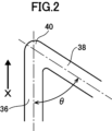
- 2 is a schematic enlarged view of a part of the air chamber of the ventilation path formed in the bag shown in FIG. 1.
- FIG. FIG. 7 is a schematic plan view of a bag for storing coffee according to another embodiment of the present invention.
- FIG. 7 is a schematic plan view of a bag for storing coffee according to another embodiment of the present invention. It is a typical drawing for explaining the air chamber of the ventilation path formed in the bag body of the embodiment of the present invention. It is a typical drawing for explaining the air chamber of the ventilation path formed in the bag body of the embodiment of the present invention.
- FIG. 7 is a schematic plan view of a bag for storing coffee according to another embodiment of the present invention.
- FIG. 7 is a schematic plan view of a bag for storing coffee according to another embodiment of the present invention.
- FIG. 7 is a schematic plan view of a bag for storing coffee according to another embodiment of the present invention.
- FIG. 1 is a schematic perspective view showing the configuration of an anvil of an ultrasonic bonding machine used to manufacture a bag for storing coffee according to an embodiment of the present invention.
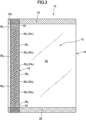
- FIG. 1 is a plan view of a bag 10 for storing coffee according to a preferred embodiment of the present invention.
- coffee includes coffee beans, roasted coffee beans, and roasted and powdered coffee beans.
- the bag of this embodiment is suitable for storing 60g or more and 2000g or less of coffee. If the amount of coffee to be stored is less than 60g, the amount of carbon dioxide generated is small, so the internal space and ventilation channels of the bag cannot be filled with carbon dioxide, and oxygen remains inside the bag, reducing the quality of the coffee. There are cases where On the other hand, if the amount of coffee exceeds 2000 g, the amount of carbon dioxide generated will be large and it will be difficult to discharge it sufficiently, causing the bag to expand and possibly burst.
- the bag 10 is made by folding a single rectangular film 12 into two pieces along a folding part 14, which is a horizontal center line, so that both side ends 12a overlap. It has a rectangular shape.
- the two films are joined to each other by ultrasonic welding to form a band-shaped joining region 16, which will be described later.
- the upper and lower ends of the two stacked films are also joined to form a top seal section 18 and a bottom seal section 20, respectively.
- the bag body 10 includes an internal space 22 that is rectangular in plan view and is surrounded on four sides by the folded portion 14, the band-shaped joint region 16, the top seal portion 18, and the bottom seal portion 20. is said to be a space that accommodates coffee.
- the stacked films 12 are joined by heat sealing to form an airtight structure.
- the widths of the top seal portion 18 and the bottom seal portion 20 are preferably set to, for example, 3 mm or more and 20 mm or less, and more preferably 5 mm or more and 15 mm or less.
- the bag 10 has a longitudinal length of 10 cm or more and 60 cm or less, and a lateral length of 6 cm or more and 40 cm or less.
- the effects of this embodiment can be effectively achieved by combining the dimensions of the bag and the amount of coffee stored above. Furthermore, by setting the size of the bag within this range, the bag can be easily handled.
- the above dimensions may be, for example, a length of 10 cm or more and 60 cm or less, and a lateral length of 10 cm or more and 40 cm or less.
- the size of the bag and the amount of coffee should be determined by the following: vertical length of the bag (cm) x horizontal length of the bag (cm) ⁇ amount of coffee (g): 0.5 cm 2 /g or more It is preferable that the condition of 2.2 cm 2 /g or less is satisfied.
- the barrier film used as the film in this embodiment includes a film made of a polymer containing vinyl alcohol or vinylidene chloride as a constituent, a polymer film deposited with silica, alumina, or aluminum, a metal foil layer, and other known films. is used.
- a film in which a base film and an oxygen barrier film are laminated, or a laminated film in which an oxygen barrier coat is provided on the base film can also be used.
- a polymer film such as polypropylene or polyethylene or a film (including paper) in which a sealant layer is provided on paper can be used.
- the barrier film used in this embodiment has a thickness of 15 ⁇ m or more and 150 ⁇ m or less, more preferably 20 ⁇ m or more and 100 ⁇ m or less. If the film thickness is less than 15 ⁇ m, the strength of the bag may be insufficient, and if it exceeds 150 ⁇ m, it will be disadvantageous in terms of cost.
- the barrier film used in this embodiment may be transparent or opaque. However, it is preferable to use an opaque packaging film to prevent the contents from deteriorating due to sunlight. Furthermore, a film whose surface is printed may be used to enhance the design. Although there are no particular restrictions on the printing method, an inkjet method is preferred since it is easily compatible with small-scale production.
- the coffee storage bag 10 of this embodiment includes the band-shaped joining region 16 in which the two ends 12a of the film are overlapped and joined by ultrasonic welding.
- This band-shaped joining region 16 has a rectangular shape with substantially the same width.
- the strip-shaped joining region 16 is formed along the edge of the bag 10 formed by the edge 12a of the film 12, in the direction of arrow X in FIG. extends over the entire length of.
- the band-like joining region 16 is provided at the side seal portion of the bag body 10, but it may be provided at other portions of the bag body, for example, other seal portions such as the center seal portion.
- the width of the band-shaped joining region 16 is preferably 5 mm or more and 20 mm or less, and more preferably 6 mm or more and 15 mm or less. If the width of the band-shaped joint region 16 is less than 5 mm, the strength of the bag may be insufficient, and if it exceeds 20 mm, it may be undesirable in terms of design.
- the band-shaped joining region 16 is formed by ultrasonic welding, but other forming methods may be used. For example, it may be formed using adhesive or heat sealing. It is preferable to use the ultrasonic bonding method from the viewpoints of forming an accurately shaped ventilation path and bonding speed.
- At least one ventilation passage 24 is formed in the band-shaped joint region 16 to communicate the interior space 22 of the bag body 10 with the outside.
- the ventilation path 24 is an elongated portion formed by unbonding the overlapping films 12 in the band-like bonding region 16, and is a portion that takes the form of an elongated flow path by storing gas inside. Therefore, gas can pass through the interior.
- the ventilation path 24 includes an air chamber 26 which is a substantially rectangular wave-shaped space that extends along the edge of the film and is sealed at both ends, and an internal ventilation that communicates the air chamber 26 with the internal space 22 of the bag body 10. 28 and an external ventilation path 30 that communicates the air chamber 26 with the external space of the bag body 10.
- the air passage 24 includes an internal air passage 28, a portion (section or section) of the air chamber 24 whose one end communicates with the internal air passage 28, and a portion of the air chamber adjacent to the internal air passage 28. It is constituted by an external ventilation path 30 that communicates with the other end of the (section). Since the bag body 10 of FIG. 1 is provided with one internal ventilation passage 28 and one external ventilation passage 30, the bag body 10 includes a passageway 28 extending from the internal passageway 28 to the external ventilation passage 30 via the air chamber 26. This means that one ventilation path 24 is provided. The internal space 22 of the bag 10 is brought into fluid communication with the outside through the ventilation path 24.
- one bag body 10 is provided with one ventilation passage, but the number of ventilation passages in one bag body 10 is not limited.
- the band-like joint region is provided at a position parallel to the longitudinal direction of the bag. Specifically, it is preferable that the band-like joining region is provided in a side seal part or a center seal part (back sticking part) parallel to the longitudinal direction of the bag.
- the dimensions of the bag body and the number of ventilation passages are shown according to the coffee content. If the coffee content is 60g or more and less than 150g, the length of the bag in the vertical direction should be 15cm or more and less than 24cm, the horizontal length of the bag should be 6cm or more and less than 11cm, and there should be one to four ventilation channels. An example of this is a form in which a If the content of coffee is 150g or more and less than 250g, the length of the bag in the vertical direction should be 20cm or more and less than 30cm, the horizontal length of the bag should be 8.5cm or more and less than 12cm, and the bag should have 1 to 6 pieces. An example is a configuration in which a ventilation path is provided.
- the length of the bag in the vertical direction should be 24cm or more and less than 34cm
- the horizontal length of the bag should be 8.5cm or more and less than 13cm
- the bag should have 2 to 8 pieces.
- An example is a configuration in which a ventilation path is provided.
- the length of the bag in the vertical direction should be 30cm or more and less than 40cm
- the horizontal length of the bag should be 10cm or more and less than 20cm
- An example is a form in which a road is provided. If the coffee content is 600g or more and less than 1200g, the length of the bag in the vertical direction should be 35cm or more and less than 45cm, the horizontal length of the bag should be 15cm or more and less than 40cm, and there should be at least 6 but not more than 12 vents. An example is a form in which a road is provided.
- the length of the bag in the vertical direction should be 40cm or more and less than 60cm
- the horizontal length of the bag should be 20cm or more and less than 40cm
- An example is a form in which a road is provided.
- the air chamber 26 has a substantially rectangular wave-like planar shape and is arranged so as to extend within the strip-shaped joining region 16 in the longitudinal direction of the strip-shaped joining region 16 .
- substantially rectangular waves are not limited to a series of strictly rectangular waves, but those that have an angle other than 90 degrees between the horizontal and vertical parts, or those that are curved in a rounded manner. Including things.
- each part constituting a substantially rectangular wave does not need to be a perfect straight line, and portions with a slight bend are also included in the "substantially rectangular wave.”
- the "substantially rectangular wave” is a series of "rectangular" portions having the same size and shape, and has a shape that is vertically symmetrical (horizontally on the bag).
- the air chamber 26 is formed in a direction substantially parallel to the end 12a of the film 12 (the direction of X in FIG. 2), and the two films 12 are joined around the periphery. Furthermore, one end 32 and the other end 34 of the air chamber 26 are sealed by joining two films 12 around the periphery.
- FIG. 2 is an enlarged view schematically showing a part of the air chamber 26.
- the air chamber 26 of the bag 10 of this embodiment has a substantially linear horizontal portion 36 extending substantially parallel to the end 12a of the film 12 in the direction in which the rectangular wave extends;
- a vertical portion 38 extends from each end of the portion 36 at an internal angle of ⁇ with respect to the horizontal portion 36 in a direction connecting the internal space 22 and external space of the bag 10, and serves as a joint between the horizontal portion 36 and the vertical portion 38.
- bent portions 40 By providing a plurality of bent portions 40, a rectangular wave-like shape is exhibited.
- the angle ⁇ which is the internal angle of the bent portion 40, is set to 40 degrees or more and 120 degrees or less.
- the strength of the bag can be increased by setting the angle of the bent part to 40 degrees or more and 120 degrees or less. Furthermore, by setting this angle to 45 degrees or more and 85 degrees or less, more preferably 50 degrees or more and 80 degrees or less, in addition to increasing the strength of the bag, when the volume of the bag changes momentarily, the inside of the bag This makes it possible to suppress oxygen from flowing into the air. In particular, by combining this with the method of varying the width of the air chamber 26 described above, the inflow of oxygen can be more effectively suppressed.
- the bent portions are preferably provided at about 60 to 90 locations per 10 cm length along the direction in which the rectangular wave shape extends (longitudinal direction of the bag).
- one ventilation passage 24 is configured to have 15 or more and 90 or less bends.
- the number of bent portions 40 provided in one ventilation path 24 is more preferably 20 or more and 80 or less.
- the length of the air chamber 26 is preferably 200 mm or more and 2400 mm or less, more preferably 300 mm or more and 2000 mm or less, and even more preferably 400 mm or more and 1600 mm or less.
- the length of the ventilation path 24 is preferably 40 mm or more and 320 mm or less, more preferably 60 mm or more and 300 mm or less, and even more preferably 80 mm or more and 280 mm or less.
- the width of the air chamber 26 is substantially constant over the entire length of the air chamber 26, and is set to 0.5 mm or more and 5 mm or less.
- the width of the air chamber 26 is preferably 0.6 mm or more and 4 mm or less, more preferably 0.7 mm or more and 3.5 mm or less.
- the area of the air chamber 26 in plan view is set to 75 mm 2 or more and 2000 mm 2 or less. It is preferably 100 mm 2 or more and 1750 mm 2 or less, more preferably 200 mm 2 or more and 1500 mm 2 or less.
- the area of the air chamber 26 is set to 75 mm 2 or more, it becomes possible to effectively suppress the inflow of oxygen. Further, by setting the area of the air chamber 26 to 2000 mm 2 or less, the bag can have sufficient strength.
- the width of the internal air passage 42 is set to 0.5 mm or more and 3 mm or less.
- the width of the internal air passage 42 is more preferably 0.7 mm or more and 2.5 mm or less.
- the length of the internal ventilation path 42 is set to 0.5 mm or more and 5 mm or less.
- the length of the internal ventilation path 42 is more preferably 0.6 mm or more and 4 mm or less, and even more preferably 0.7 mm or more and 3 mm or less.
- the length of the external ventilation path 44 is set to 0.5 mm or more and 5 mm or less.
- the length of the internal ventilation path 42 is more preferably 0.6 mm or more and 4 mm or less, and even more preferably 0.7 mm or more and 3 mm or less.
- the width of the external ventilation path 44 is set to 0.5 mm or more and 3 mm or less.
- the width of the external air passage 42 is more preferably 0.7 mm or more and 2.5 mm or less.
- the ratio of the width of the air chamber 26 to the width of the external air passage 44 is set to 0.7 or more and less than 1.0. By setting this ratio to 0.7 or more and less than 1.0, it is possible not only to discharge carbon dioxide and prevent oxygen from flowing in, but also to prevent oxygen from flowing into the bag when a sudden volume decrease occurs.
- the ratio of the width of the air chamber 26 to the width of the external air passage 44 is more preferably 0.75 or more and 0.97 or less.
- FIG. 3 when a plurality of internal air passages 28 and external air passages 30 are provided (in this example, three each), they are arranged along the length direction of the air chamber 26 extending in a rectangular wave shape. , internal ventilation passages 28 and external ventilation passages 30 are provided alternately.
- the bag shown in FIG. 3 includes an internal ventilation passage 28, a part of the air chamber 26 communicating with the internal ventilation passage 28, and an external ventilation passage 30 adjacent to the internal ventilation passage 28 and communicating with a part of the air chamber 28. This means that five ventilation paths are provided.
- the bag body 10 in FIG. 3 includes a first internal air passage 28 1 located on the upper side and a first portion 26 of the air chamber 26 that communicates with the first internal air passage 28 1 (on the upper side). 1 and a first external ventilation path 30 1 adjacent to the first internal ventilation path 28 1 in the longitudinal (propagation) direction of the rectangular wave drawn by the air chamber, the first ventilation path 24 1 is configured. .
- a second ventilation path 24 2 is constituted by another second external ventilation path 30 2 adjacent to the first internal ventilation path 28 1 in the longitudinal direction (opposite to the above-mentioned propagation).
- a second internal air passage 28 2 located in the middle, a third portion 26 3 of the air chamber 26 that communicates with the second internal air passage 28 2 (on the upper side), and a rectangular wave drawn by the air chamber.
- a third ventilation passage 24 3 is constituted by a third external ventilation passage 30 3 adjacent to the second internal ventilation passage 28 2 in the longitudinal (propagation) direction.
- a fourth ventilation path 24 4 is constituted by another third external ventilation path 30 3 adjacent to the second internal ventilation path 28 2 in the longitudinal direction (opposite to the above-mentioned propagation).
- a fifth ventilation path 24 5 is constituted by a third external ventilation path 30 3 adjacent to the third internal ventilation path 28 3 in the longitudinal (propagation) direction.
- Carbon dioxide generated by the coffee inside the bag body 10 is exhausted to the outside through each of the air passages 24 1-5 having such a configuration. Moreover, since the ventilation path 24 is filled with carbon dioxide during coffee storage, oxygen is also prevented from entering the interior space 22 of the bag body 10 through the ventilation path 24.
- one air chamber 26 is provided in the band-like joint region 16 of the bag 10, and one or five air passages 24 are formed by this one air chamber 26. there were.
- the present invention provides a plurality of independent air chambers 26a, 26b (for example, 2 to 6, 2 in FIG. 4) in the band-shaped joint region 16, and each By providing at least one internal ventilation passage 28 and one external ventilation passage 30 in each of the air chambers 26a and 26b, two or more ventilation passages 24a and 24b may be formed in one strip-shaped joint region 16. According to such a configuration, even if one ventilation passage stops functioning due to clogging with foreign matter, etc., it is possible to exert a certain degree of carbon dioxide evacuation function.
- the air chamber 26 is set so that the sum of two internal angles ⁇ and ⁇ (FIG. 5) of one rectangular wave is 150 degrees or more and 240 degrees or less.
- the strength of the bag 10 can be increased, and furthermore, when the volume of the bag 10 changes instantaneously, the inside of the bag 10 This makes it possible to suppress oxygen from flowing into the air.
- the value of the angle ⁇ is 40 degrees or more and 90 degrees or less, preferably 45 degrees or more and 70 degrees or less, and more preferably 50 degrees or more and 60 degrees or less.
- the value of the angle ⁇ is 90 degrees or more and 140 degrees or less, preferably 110 degrees or more and 135 degrees or less, and more preferably 120 degrees or more and 130 degrees or less.
- ⁇ and ⁇ satisfy the following conditions. 40 degrees ⁇ 90 degrees, 90 degrees ⁇ 140 degrees, and 160 degrees ⁇ + ⁇ 200 degrees
- the vertical portion 38 of the air chamber 26 is arranged within a region having a width of 50% or more and 98% or less of the width of the band-shaped joint region 16.
- the vertical portion 38 of the air chamber 26 is preferably arranged in a region having a width of 55% or more and 95% or less of the width of the band-shaped joint region 16, and preferably in a region having a width of 60% or more and 90% or less. It is further preferable that the
- the length of the virtual straight line Lc is At, and the length of each part where two films are joined on the virtual straight line Lc (Ad 1 , Ad 2 Ad 3 Ad 14 . . .
- Ad the sum of Ad 11
- the value of Ad/At is configured to be 0.10 or more and 0.75 or less. If the value of Ad/At is less than 0.10, the strength of the bag 10 will be insufficient, and the bag may be damaged when it falls from a high place.
- Ad/At exceeds 0.75, the width of the air chamber becomes too small and the exhaust of carbon dioxide becomes insufficient, or the length of the air chamber becomes too short and the inflow of oxygen from the outside becomes insufficient. It may not be possible to prevent this.
- FIG. 6 is a schematic diagram of the band-shaped joint area and the ventilation passage 24 of the bag body 10 of this embodiment.
- the air chamber 26 of the air passage 24 is depicted in a largely schematic manner for clarity.
- the length of the virtual straight line Lc is defined as At, and the portion where the films are joined on the virtual straight line Lc (Ad 1 , Ad 2 Ad 3 Ad 14 ...Ad 11 in FIG. 6) That is, when the total length of the portion that does not cross the air chamber 26 (specifically, the vertical portion 38 of the air chamber 26) is defined as Ad, the value of Ad/At is 0.10 or more and 0.75 or less.
- the air chamber 26 had a constant width over its entire length, that is, the width of the horizontal portion 36 and the vertical portion 38 were equal.
- the air chamber 26 may be configured to have partially different widths.
- the width of the horizontal portion 36 is narrower than the width of the vertical portion 38 as in the bag shown in FIG.
- the width may be narrower than the width of the portion 36.
- the width may vary within the vertical portion 38. Even with such a configuration, it is possible to effectively prevent oxygen inflow due to rapid volume changes.
- the ratio between the widest part and the narrowest part is 1.2 or more and 3 or less, more preferably 1.5 or more and 2.5 or less.
- an ultrasonic bonding machine is used to form the band-shaped bonded region of the bag.
- An ultrasonic bonding machine consists of an ultrasonic oscillator that converts commercial electricity of 50 Hz or 60 Hz into a high frequency signal of approximately 15 to 70 KHz, a converter that converts this signal into mechanical vibration, and a booster that amplifies this mechanical vibration.
- This is an ultrasonic welding machine with a known configuration, which includes a disc-shaped horn that transmits amplified vibrations to the welding target, a disc-shaped anvil that holds two ends of the film between the horn, and the like.
- the horn and anvil are both disc-shaped and rotate while sandwiching the two ends of the film to continuously form a band-like bonding area at the two ends of the overlapping film. Note that the horn and anvil are rotationally driven by a drive device (not shown).
- FIG. 10 is a schematic perspective view showing the configuration of an anvil 50 used in an ultrasonic bonding machine.
- the anvil 50 has a disk-like shape, and a convex portion 54 is formed on the outer circumferential surface 52 to form a band-like joint region of the bag.
- a groove 56 corresponding to the planar shape of the air passage 24 of the bag is formed in the convex portion 54 .
- the height of the convex portion 54 and the depth of the groove 56 are preferably 0.2 mm or more and 1.0 mm or less, more preferably 0.25 mm or more and 0.8 mm or less, and even more preferably 0.3 mm or more and 0.5 mm or less. If the height of the convex portion 54 and the depth of the groove 56 are less than 0.2 mm, the bonding strength of the band-shaped bonding area may be insufficient, and if it exceeds 1.0 mm, the film will break at the edges and will not be bonded properly. There are cases. The height of the convex portion 54 and the depth of the groove 56 may be the same or different.
- the cross-sectional shapes of the convex portions 54 and the grooves 56 are preferably rectangular, semicircular, or trapezoidal, but from the viewpoint of preventing the film from being cut at the edges, semicylindrical or trapezoidal shapes are preferable.
- the horn used in the ultrasonic bonding machine of this embodiment is disc-shaped and has a smooth outer peripheral surface.
- the diameter of the horn and anvil is approximately 50 mm to 150 mm, and the width of the outer peripheral surface of the horn and anvil is approximately 7 mm to 25 mm, corresponding to the width of the band-shaped joint area.
- known materials can be used for the horn and anvil, stainless steel and titanium alloy are particularly preferred.
- edges of the outer peripheral surfaces of the horn and anvil may be chamfered. By chamfering, it is possible to prevent the film from being cut at this part.
- holes (cutouts) may be formed on the sides of the horn and anvil to reduce weight.
- the joining speed is preferably about 5 m/min or more and 50 m/min or less, more preferably 150 m/min or more and 45 m/min or less, and even more preferably 20 m/min or more and 40 m/min or less.
- driving speed is preferably about 5 m/min or more and 50 m/min or less, more preferably 150 m/min or more and 45 m/min or less, and even more preferably 20 m/min or more and 40 m/min or less.
- a pressure of about 20N to 500N is applied between the horn and the anvil by a pressure device.
- an ultrasonic welding machine has been described that includes an anvil with a convex portion on the outer circumferential surface and a horn with a smooth outer circumferential surface
- another embodiment may include an anvil with a smooth outer circumferential surface and a horn with a convex portion on the outer circumferential surface.
- An ultrasonic bonding machine equipped with a horn may also be used.
- barrier film (2) This film is folded in two and this part is ultrasonically bonded with a disc-shaped anvil having irregularities corresponding to the band-shaped bonding area on the circumferential surface and a disc-shaped horn with a smooth circumferential surface. They are joined by a machine to simultaneously form a band-like joint area, an air chamber, an internal ventilation path, an external ventilation path, and a ventilation path. It is preferable to use this portion as a side seal portion or a back sticker portion. (3) Next, a bottom seal portion is formed by a method such as heat sealing. When forming the bottom seal part, it is also possible to form the sealing part on the lower side of the air chamber at the same time. (4) Next, a top seal portion is formed by a method such as heat sealing. When forming the top seal part, it is also possible to form the sealing part above the air chamber at the same time.
- the above explanation is a method for creating bags one by one, but it is also possible to create multiple bags by continuously forming the band-like joining areas of multiple bags using one sheet of film, and then cutting the film. good. This method is preferred because the bag can be manufactured very efficiently.
- a method may be used in which a bag is formed by the method described above, coffee is filled before forming the top seal, and then the top seal is formed.
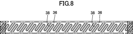
- Example 1 An ultrasonic welding machine was used in which the horn and anvil were disk-shaped, and the anvil had a protrusion formed on its outer circumferential surface that corresponded to a belt-shaped welding area having an air chamber in the shape of Fig. 8. .
- the outer peripheral surface of the horn is smooth.
- a barrier film (nylon film with barrier layer/laminated low-density polyethylene film) with a width of 30 cm, a length of 100 cm, and a thickness of 85 ⁇ m is folded in half, the two ends are overlapped, and ultrasonic bonding is performed to form a band-shaped bonded area. Formed.
- the width of the band-like bonding region was 10 mm, and it was formed over 100 cm along the length of the film.
- the oscillation frequency of the horn of the ultrasonic bonding machine was 20 KHz, the vibration amplitude was 15 ⁇ m, the pressing pressure was 250 N, and the bonding speed was 25 m/min.
- a bag intermediate body was created in which four bags each measuring 25 cm in length and 15 cm in width were connected in the vertical direction.
- a portion 25 cm from the upper end of the intermediate body of this bag was heat-sealed in the width direction to form a bottom seal portion with a width of 3 mm, and at the same time, the lower end of the air chamber was sealed.
- the bottom seal portion was cut in the width direction to obtain a bag measuring 25 cm in length and 15 cm in width. Thereafter, 100 g of coffee beans (Guatemalan peaberry) were placed in the bag, and the inside of the bag was filled with nitrogen gas. Immediately thereafter, a top seal portion having a width of 3 mm was formed by heat sealing, and the bag was closed.
- coffee beans Guatemalan peaberry
- a bag containing coffee beans was created.
- a bag in which the remaining bag intermediate contained three coffee beans was prepared in the same manner.
- This bag has a band-shaped joint area of the present invention in the side seal portion, and a ventilation passage is formed in this portion.
- the number of ventilation passages is 3, and the length of each ventilation passage is 265 mm.
- each air passage has 20 bends, of which 10 have a bend angle of 80 degrees and the other 10 have a bend angle of 100 degrees.
- the width of the ventilation passage is 2 mm, but the width at the bent portion is 4 mm.
- Example 2 Example 2 was carried out in the same manner as Example 1, except that the size of the bag was 27 cm long and 15 cm wide, and the shape of the ventilation path was changed as follows. Results similar to those in Example 1 were obtained.
- the shape of the air chamber was as shown in Figure 3. Other shapes are as follows. - The length of the ventilation path is 260 mm, and the number of ventilation paths is 3. - Width of the ventilation passage: The width of the portion approximately parallel to the edge of the film is 1.5 mm, and the width of the portion approximately perpendicular to the edge of the film is also 1.5 mm. - The internal angle ⁇ of the bent portion is 56 degrees, and the internal angle ⁇ is 124 degrees.
- Example 3 Example 3 was carried out as described below, except that the shape of the ventilation path was changed as follows, and the same results as in Example 1 were obtained.
- the shape of the air chamber was as shown in Figure 7.
- Other shapes are as follows.
- - The length of the ventilation path is 260 mm, and the number of ventilation paths is 3.
- Width of the ventilation passage The width of the portion approximately parallel to the edge of the film is 1.5 mm, and the width of the portion approximately perpendicular to the edge of the film is 3.0 mm.
- the internal angle ⁇ of the bent portion is 56 degrees, and the internal angle ⁇ is 124 degrees.
- the number of bends in each air passage having an angle of 56 degrees is 19, and the number of bends having an angle of 124 degrees is 19.
- Ad/At 0.21.
- the area of the air chamber is 1440mm 2 .
- the widths of the external ventilation path and the internal ventilation path are both 1.2 mm, and the ratio of the width of the minimum width of the ventilation path to the width of the external ventilation path is 0.8.
- Example 4 Example 4 was carried out as described below, except that the shape of the ventilation path was changed as follows, and the same results as Example 1 were obtained.
- the shape of the air chamber was as shown in Figure 3. Other shapes are as follows.
- - The length of the ventilation path is 390 mm, and the number of ventilation paths is 1.
- - Width of the ventilation passage The width of the portion 42 that is approximately parallel to the edge of the film is 1.5 mm, and the width of the portion 43 that is approximately perpendicular to the edge of the film is also 1.5 mm.
- the internal angle ⁇ of the bent portion is 65 degrees, and the internal angle ⁇ is 115 degrees.
- the number of bends in the ventilation passage having an angle of 65 degrees is 29, and the number of bends having an angle of 115 degrees is 29.
- the value of Ad/At is 0.21.
- the area of the air chamber is 1170mm 2 .
- the widths of the external ventilation path and the internal ventilation path are both 1.2 mm, and the ratio of the width of the minimum width of the ventilation path to the width of the external ventilation path is 0.8.
- Bag body 12 Film 12a (film) side end 16: Band-shaped joint area 22: Internal space 24: Ventilation path 26: Air chamber 28: Internal ventilation path 30: External ventilation path 32: (Air chamber) end Part 34: End part 36 (of the air chamber): Horizontal part 38 (of the air chamber): Vertical part 40 (of the air chamber): Bent part
Landscapes
- Engineering & Computer Science (AREA)
- Mechanical Engineering (AREA)
- Food Science & Technology (AREA)
- Packages (AREA)
- Bag Frames (AREA)
Abstract
二酸化炭素の排出と酸素の侵入の抑制に加え、充分な強度を持ち、急激な容積変化に伴う外気の流入を防止できるコーヒー保存用袋体等を提供すること。 本発明によれば、本発明によれば、60g以上2000g以下のコーヒーを保存するためのコーヒー保存用袋体10であって、フィルムの2つの端部12aが互いに重ねられ接合されている帯状接合領域16を備え、帯状接合領域内に、フィルムを非接合とすることにより形成されフィルムの端部に沿って延び両端部分が封止された略矩形波形状の空間である気室26と、気室と内部空間とを連通する内部通気路28、気室と外部空間とを連通する外部通気路30とが通気路24を構成するように設けられ、気室は、フィルムの端部に略平行に矩形波の延びる方向に延びる略直線状の横部分36と、横部分に対して40度以上120度以下の角度をなして袋体の内部空間と外部空間とを結ぶ方向に延びる縦部分38と、横部分と縦部分との接合部となる屈曲部40を有しているコーヒー保存用袋体が提供される。
Description
本発明はコーヒー保存用袋体、およびその製造方法に関する。詳細には、袋体内で発生する二酸化炭素を袋体外に排出することが可能で、さらに袋体内のコーヒーを、劣化を防止しながら、長期間にわたり安定した品質で保存することが可能なコーヒー保存用袋体およびその製造方法に関する。
コーヒー(豆、あるいは粉)は、保存中に酸素に触れると品質が劣化するため、コーヒーを保管する保存用の袋体には、外部から酸素が侵入することを防止する性能が求められる。
一方、保存中にコーヒーが発生させた二酸化炭素によって袋体が膨張し、場合によっては破裂するおそれがあるので、保存中に袋体内でコーヒーが発生させた二酸化炭素を袋体の外に排出する必要がある。特にコーヒーの場合、青果物や生花に比べ、長期間にわたり保存されることが多いため、高い酸素侵入防止機能および二酸化炭素排出機能が求められている。
一方、保存中にコーヒーが発生させた二酸化炭素によって袋体が膨張し、場合によっては破裂するおそれがあるので、保存中に袋体内でコーヒーが発生させた二酸化炭素を袋体の外に排出する必要がある。特にコーヒーの場合、青果物や生花に比べ、長期間にわたり保存されることが多いため、高い酸素侵入防止機能および二酸化炭素排出機能が求められている。
このような要求を満たすため、コーヒーを保存する袋に逆止弁を取付ける方法も実施されているが、逆止弁はコストが高く、さらに逆止弁を取付けた袋体は製造工程が煩雑となるという問題がある。
この欠点を改良する構成として、袋体の内部と外部をつなぐ長い通気路を持つ袋体が提案されている(特許文献1、2)。この構成を用いると、酸素の侵入による劣化を抑制して、袋体の膨らみを発生させない状態でコーヒーを保存することが可能となる。
しかしながら、保存中に、袋体を床に落下させる等して袋体に外力が作用すると、袋体が破損することがある。
また、外力が加わり、袋体が破損しないまでも、その容積が急激に変化すると、容積変化に伴い袋体内部に酸素を含む外気が侵入し、袋体内部のコーヒーの劣化を充分に抑制できなくなることがある。
特許文献1、2の構成は二酸化炭素の排出と酸素流入防止の両立に関しては非常に有効であるが、袋体の強度および急激な容積変化に伴う外気流入の防止に関しては必ずしも充分ではなかった。
したがって、二酸化炭素の排出と酸素の侵入の抑制に加えて、充分な強度と急激な体積変化に伴う外気の流入を抑制する技術が望まれていた。
本発明は、二酸化炭素の排出と酸素の侵入の抑制に加えて、充分な強度を持ち、急激な容積変化に伴う外気の流入を防止できるコーヒー保存用袋体を提供することを目的とする。
さらにそのようなコーヒー保存用袋体の製造方法、及び上記コーヒー保存用袋体を用いたコーヒーの保存方法を提供することである。
さらにそのようなコーヒー保存用袋体の製造方法、及び上記コーヒー保存用袋体を用いたコーヒーの保存方法を提供することである。
本発明の好ましい態様によれば、
60g以上2000g以下のコーヒーを保存するためのコーヒー保存用袋体であって、
前記袋体は、バリアフィルムによって形成され、縦方向の長さが10cm以上60cm以下、横方向の長さが6cm以上40cm以下であり、
前記フィルムの2つの端部が互いに重ねられ接合されている帯状接合領域を備え、
前記帯状接合領域内に、前記フィルムを非接合とすることにより形成され前記フィルムの端部に沿って延び両端部分が封止された略矩形波形状の空間である気室と、前記気室と前記袋体の内部空間とを連通する内部通気路、前記気室と前記袋体の外部空間とを連通する外部通気路とが設けられ、
前記内部通気路と、該内部通気路に連通した前記気室の部分と、前記内部通気路に隣接し前記気室の部分に連通した外部通気路と、によって、前記袋体の内部と外部とを連通する通気路が構成され、
前記気室は、前記フィルムの端部に略平行に前記矩形波の延びる方向に延びる略直線状の横部分と、該横部分に対して40度以上120度以下の角度をなして前記袋体の内部空間と外部空間とを結ぶ方向に延びる縦部分と、前記横部分と縦部分との接合部となる屈曲部を有している、
ことを特徴とするコーヒー保存用袋体が提供される。
本発明の他の好ましい態様によれば、
60g以上2000g以下のコーヒーを保存するためのコーヒー保存用袋体であって、
前記袋体は、バリアフィルムによって形成され、縦方向の長さが10cm以上60cm以下、横方向の長さが6cm以上40cm以下であり、
前記フィルムの2つの端部が互いに重ねられ接合されている帯状接合領域を備え、
前記帯状接合領域内に、前記フィルムを非接合とすることにより形成され前記フィルムの端部に沿って延び両端部分が封止された略矩形波形状の空間である気室と、前記気室と前記袋体の内部空間とを連通する内部通気路、前記気室と前記袋体の外部空間とを連通する外部通気路とが設けられ、
前記内部通気路と、該内部通気路に連通した前記気室の部分と、前記内部通気路に隣接し前記気室の部分に連通した外部通気路と、によって、前記袋体の内部と外部とを連通する通気路が構成され、
前記気室は、前記フィルムの端部に略平行に前記矩形波の延びる方向に延びる略直線状の横部分と、該横部分に対して所定角度をなして前記袋体の内部空間と外部空間とを結ぶ方向に延びる縦部分と、前記横部分と縦部分との接合部となる屈曲部とを有し、
一の前記横部分の一端において前記横部分と前記縦部分とがなす角度αと、前記一の横部分の他端において前記横部分と前記縦部分とがなす角度βとしたとき、α+βが150度以上240度以下となる、
ことを特徴とするコーヒー保存用袋体が提供される。
本発明の他の好ましい態様によれば、
前記通気路が、1本以上12以下、設けられている。
前記通気路が、1本以上12以下、設けられている。
本発明の他の好ましい態様によれば、
前記気室の長さが200mm以上2400mm以下である。
前記気室の長さが200mm以上2400mm以下である。
本発明の他の好ましい態様によれば、
前記通気路において、最も幅の広い部分と最も狭い部分の幅の比率が1.2以上3以下である。
前記通気路において、最も幅の広い部分と最も狭い部分の幅の比率が1.2以上3以下である。
本発明の他の好ましい態様によれば、
1本の前記通気路に、15個以上90個以下の前記屈曲部が形成されている。
1本の前記通気路に、15個以上90個以下の前記屈曲部が形成されている。
本発明の他の好ましい態様によれば、
前記内部通気路および外部通気路の幅が0.5mm以上3mm以下である。
前記内部通気路および外部通気路の幅が0.5mm以上3mm以下である。
本発明の他の好ましい態様によれば、
前記気室の幅と前記外部通気路の幅との比が0.4以上1.0未満である。
前記気室の幅と前記外部通気路の幅との比が0.4以上1.0未満である。
本発明の他の好ましい態様によれば、
前記気室は、前記縦部分が前記帯状接合領域の幅方向中央を延びる仮想直線Lcを横切って延びるように配置され、
前記気室の縦部分を通って延びる前記仮想直線の所定部分の長さをAt、長さAtの仮想直線のうち前記フィルムが接合されている部分の長さの合計をAdとき、Ad/Atが0.10以上0.75以下である。
前記気室は、前記縦部分が前記帯状接合領域の幅方向中央を延びる仮想直線Lcを横切って延びるように配置され、
前記気室の縦部分を通って延びる前記仮想直線の所定部分の長さをAt、長さAtの仮想直線のうち前記フィルムが接合されている部分の長さの合計をAdとき、Ad/Atが0.10以上0.75以下である。
本発明の他の好ましい態様によれば、
前記気室の平面視における総面積が75mm2以上2000mm2以下である。
前記気室の平面視における総面積が75mm2以上2000mm2以下である。
本発明の他の好ましい態様によれば、
前記帯状接合領域が超音波接合部である。
前記帯状接合領域が超音波接合部である。
本発明の他の好ましい態様によれば、
外周面上に前記帯状接合領域に対応する凹凸を有する円盤状アンビルと、平滑な円周面を持つ円盤状ホーンを有する超音波接合機を用いて上記のいずれかに記載のコーヒー保存用袋体を製造することを特徴とするコーヒー保存用袋体の製造方法が提供される。
外周面上に前記帯状接合領域に対応する凹凸を有する円盤状アンビルと、平滑な円周面を持つ円盤状ホーンを有する超音波接合機を用いて上記のいずれかに記載のコーヒー保存用袋体を製造することを特徴とするコーヒー保存用袋体の製造方法が提供される。
本発明の他の好ましい態様によれば、
上記いずれかのコーヒー保存用袋体に60g以上2000g以下のコーヒーを充填して保存する、コーヒーの保存方法が提供される。
上記いずれかのコーヒー保存用袋体に60g以上2000g以下のコーヒーを充填して保存する、コーヒーの保存方法が提供される。
本発明の他の好ましい態様によれば、
60g以上1200g以下のコーヒーを保存するためのコーヒー保存用袋体であって、
前記袋体は、バリアフィルムによって形成され、縦方向の長さが10cm以上60cm以下、横方向の長さが10cm以上40cm以下であり、
前記フィルムの2つの端部が互いに重ねられ接合されている帯状接合領域を備え、
前記帯状接合領域内に、前記フィルムを非接合とすることにより形成され前記フィルムの端部に沿って延び両端部分が封止された略矩形波形状の空間である気室と、前記気室と前記袋体の内部空間とを連通する内部通気路、前記気室と前記袋体の外部空間とを連通する外部通気路とが設けられ、
前記内部通気路と、該内部通気路に連通した前記気室の部分と、前記内部通気路に隣接し前記気室の部分に連通した外部通気路と、によって、前記袋体の内部と外部とを連通する通気路が構成され、
前記気室は、前記フィルムの端部に略平行に前記矩形波の延びる方向に延びる略直線状の横部分と、該横部分に対して40度以上120度以下の角度をなして前記袋体の内部空間と外部空間とを結ぶ方向に延びる縦部分と、前記横部分と縦部分との接合部となる屈曲部を有し、
前記気室は、長さが400mm以上1600mm以下、巾が0.7mm以上3.5mm以下であり、
前記内部通気路は、巾が0.5mm以上3mm以下であり、
前記外部通気路は、巾が0.5mm以上3mm以下であり、
1本の前記通気路には、20個ないし80個の屈曲部が設けられている、
ことを特徴とするコーヒー保存用袋体が提供される。
本発明によれば、二酸化炭素の排出と酸素流入の防止に加えて、充分な強度と急激な体積変化に伴う酸素流入を防止できるコーヒー保存用袋体が提供される。
さらに上記のコーヒー保存用袋体の製造方法、及び上記コーヒー保存用袋体を用いたコーヒーの保存方法が提供される。
さらに上記のコーヒー保存用袋体の製造方法、及び上記コーヒー保存用袋体を用いたコーヒーの保存方法が提供される。
発明者は、本発明のコーヒー保存用袋体が上記のような効果を奏するのは次のような理由であると推定している。まず、本発明のコーヒー保存用袋体は、通気路によって、内部で発生した二酸化炭素は通気路を排出するとともに、通気路に満たされた二酸化炭素によって、通気路を通して外部から酸素が侵入することを抑制することが可能になる。
さらに、本発明のコーヒー保存用袋体は、帯状接合領域に設けられた通気路の気室が、袋端の端部に対して40度以上120度以下の角度で折れ曲がる屈曲部を有している。このため帯状接合領域では、フィルムの端部に垂直な方向と平行な方向の両方向に対して必要十分な強度が維持されることになる。この結果、帯状接合領域に外力、特にフィルムの端部に垂直方向の引張り応力が作用したときに袋体が破損を防止することが可能になる。
さらに通気路の気室が屈曲部を有するので、流速の高い気体の流動に対して抵抗が大きくなる。このため袋体で急激な体積減少が起こったときに、袋体内部の二酸化炭素が袋体外に逃げにくい。その結果、袋体内部の圧力がわずかに上がる。その後、袋体の体積が元の値にもどると、同時に圧力も元の値にもどる。以上のような過程では酸素が袋体内部に侵入しにくい。
なお、気室が屈曲部を有している通気路であっても、コーヒーが発生させる二酸化炭素のように流速が非常に遅い気体の流れに対しては大きな抵抗にならない。そのため、通気路は、屈曲部を有していても二酸化炭素の排出を速やかに行なうことができる。
以下、本発明の実施形態の袋体を図面に沿って説明する。図1は、本発明の好ましい実施態様のコーヒー保存用の袋体10の平面図である。
本明細書において、コーヒーは、コーヒー豆、さらにこれをローストしたもの、およびローストした後粉体化したものも含む。
本実施態様の袋体は、60g以上2000g以下のコーヒーを保存するのに適する。
保存するコーヒーの量が60g未満の場合、発生する二酸化炭素量が少ないため袋体の内部空間および通気路を二酸化炭素で満たすことができず、袋体内に酸素が残留してコーヒーの品質が低下する場合がある。一方、コーヒーの量が2000gを超えると発生する二酸化炭素量が多く十分な排出が困難となり、袋体が膨張し、場合によっては破裂するおそれがある。
本実施態様の袋体は、60g以上2000g以下のコーヒーを保存するのに適する。
保存するコーヒーの量が60g未満の場合、発生する二酸化炭素量が少ないため袋体の内部空間および通気路を二酸化炭素で満たすことができず、袋体内に酸素が残留してコーヒーの品質が低下する場合がある。一方、コーヒーの量が2000gを超えると発生する二酸化炭素量が多く十分な排出が困難となり、袋体が膨張し、場合によっては破裂するおそれがある。
図1に示されているように、袋体10は、1枚の矩形状のフィルム12が、横方向中心線である折り曲げ部14に沿って、両側端部12aが重なるように2つに折り曲げられた矩形形状を有している。
2枚のフィルム12が互いに重ねられている両側端部は、超音波溶接によって2枚のフィルムが互いに接合され、後述の帯状接合領域16とされている。2枚のフィルムが重ねられた上下の端部もそれぞれ接合されて、トップシール部18およびボトムシール部20とされている。この結果、袋体10は、折り曲げ部14と、帯状接合領域16、トップシール部18およびボトムシール部20によって4辺が囲まれた平面視で矩形上の内部空間22を備え、この内部空間22がコーヒーを収容する空間とされている。
トップシール部18とボトムシール部20では、重ねあわされたフィルム12がヒートシールによって接合され気密構造となっている。トップシール部18およびボトムシール部20の幅は、例えば3mm以上20mm以下に設定されるのが好ましいが、5mm以上15mm以下がより好ましい。トップシール部18、ボトムシール部20の幅を3mm以上とすることで、シール強度を保つことが可能になり、20mm以下とすることで均一な接合が可能になる。
本実施態様では、袋体10は、縦方向の長さが10cm以上60cm以下、横方向の長さが6cm以上40cm以下である。この袋体の寸法と、上記のコーヒーの保存量を組み合わせることにより、本実施形態の効果が有効に得られる。さらに袋体の大きさをこの範囲とすることで、袋体の取り扱い性が良好になる。上記寸法は、例えば、長さが10cm以上60cm以下、横方向の長さが10cm以上40cm以下でもよい。
袋体の大きさとコーヒーの量は、袋体の縦方向の長さ(cm)×袋体の横方向の長さ(cm)÷コーヒーの量(g)の値が0.5cm2/g以上2.2cm2/g以下という条件を満たしていることが好ましい。
本実施態様でフィルムとして用いられるバリアフィルムとしては、ビニルアルコールまたは塩化ビニリデンを構成成分として含むポリマーからなるフィルム、シリカ、アルミナ、アルミニウムのいずれかを蒸着したポリマーフィルム、金属箔層などの公知のフィルムが使用される。
さらに、基材フィルムと酸素バリアフィルムを積層したフィルム、基材フィルムに酸素バリアコートを設けた積層フィルムを用いることもできる。基材フィルムとしては、ポリプロピレン、ポリエチレンなどのポリマーフィルムや紙にシーラント層を設けたフィルム(紙を含む)などを用いることができる。
本実施態様で用いられるバリアフィルムは、厚さが15μm以上150μm以下、より好ましくは20μm以上100μm以下である。フィルムの厚さが15μm未満の場合、袋体の強度が不充分になるおそれがあり、150μmを超えるとコスト上、不利になる。
本実施態様で用いられるバリアフィルムは、透明であっても不透明であってもよい。しかしながら、内容物が日光による劣化を防止するため、不透明な包装フィルムを用いることが好ましい。また、意匠性を高めるために表面に印刷をしたフィルムを使用してもよい。
印刷方法には特に制限はないが、少量生産に対応しやすい点からインクジェット方式が好ましい。
印刷方法には特に制限はないが、少量生産に対応しやすい点からインクジェット方式が好ましい。
次に、帯状接合領域16の構成について説明する。
本実施態様のコーヒー保存用袋体10は、上述のように、フィルムの2つの端部12aが重ね合わされて超音波溶接で接合された帯状接合領域16を備えている。この帯状接合領域16は、略同一幅で矩形形状を有している。帯状接合領域16は、フィルム12の端部12aによって形成された袋体10の端部に沿って、フィルム12の端部12aと略平行な図2の矢印Xの方向に、フィルムの端部21の全長にわたって延びている。
本実施態様では、袋体10のサイドシール部に帯状接合領域16を設けたが、袋体の他の部分、例えば、センターシール部等の他のシール部分に設けてもよい。
本実施態様のコーヒー保存用袋体10は、上述のように、フィルムの2つの端部12aが重ね合わされて超音波溶接で接合された帯状接合領域16を備えている。この帯状接合領域16は、略同一幅で矩形形状を有している。帯状接合領域16は、フィルム12の端部12aによって形成された袋体10の端部に沿って、フィルム12の端部12aと略平行な図2の矢印Xの方向に、フィルムの端部21の全長にわたって延びている。
本実施態様では、袋体10のサイドシール部に帯状接合領域16を設けたが、袋体の他の部分、例えば、センターシール部等の他のシール部分に設けてもよい。
本実施態様では、帯状接合領域16の幅は5mm以上20mm以下が好ましく、6mm以上15mm以下であることがより好ましい。帯状接合領域16の幅が5mm未満の場合、袋体の強度が不充分になる場合があり、20mmを超えると意匠上、好ましくない場合がある。
本実施態様では、帯状接合領域16は超音波溶接で形成されているが、他の形成方法を用いても良い。例えば、接着剤、ヒートシールで形成してもよい。
超音波接合法を用いることは、正確な形状の通気路を形成できる点や接合速度の点から好ましい。
超音波接合法を用いることは、正確な形状の通気路を形成できる点や接合速度の点から好ましい。
帯状接合領域16には、袋体10の内部空間22と外部を連通させる、少なくとも1本の通気路24が形成されている。通気路24は、帯状接合領域16において、重なったフィルム12を非接合とすることにより形成された細長い部分であり、内部に気体が収容されることにより細長い流路の形態を取る部分である。したがって、内部をガスが通過可能である。
通気路24は、フィルムの端部に沿って延び両端部分が封止された略矩形波形状の空間である気室26と、気室26と袋体10の内部空間22とを連通させる内部通気路28と、気室26と袋体10の外部空間とを連通させる外部通気路30とによって構成されている。
通気路24は、フィルムの端部に沿って延び両端部分が封止された略矩形波形状の空間である気室26と、気室26と袋体10の内部空間22とを連通させる内部通気路28と、気室26と袋体10の外部空間とを連通させる外部通気路30とによって構成されている。
詳細には、通気路24は、内部通気路28と、の一端がこの内部通気路28と連通する気室24の一部分(区分即ち区間)と、この内部通気路28に隣接し気室の一部分(区間)の他端に連通した外部通気路30によって構成される。図1の袋体10には、内部通気路28および外部通気路30が一つずつ設けられているので、袋体10には、内部通路28から気室26を経て外部通気路30に至る、1本の通気路24が設けられていることになる。
そして、袋体10の内部空間22は、この通気路24によって、外部と流体連通されることになる。
そして、袋体10の内部空間22は、この通気路24によって、外部と流体連通されることになる。
上記実施形態では、1つの袋体10に1本の通気路が設けられている構成であったが、1つの袋体10における通気路の本数は、限定されるものではない。
本発明のコーヒー保存用袋体においては、帯状接合領域は袋体の縦方向に平行な位置に設ける事が好ましい。具体的には、帯状接合領域は袋体の縦方向に平行なサイドシール部またはセンターシール部(背貼り部)に設けることが好ましい。
コーヒー内容量に応じた、袋体の袋体の寸法および通気路の本数の好ましい例を示す。コーヒー内容量が60g以上150g未満の場合には、袋体の縦方向の長さを15cm以上24cmm未満、袋体の横方向の長さを6cm以上11cm未満とし、1本ないし4本の通気路を設けた形態が挙げられる。
コーヒー内容量が150g以上250g未満の場合には、袋体の縦方向の長さを20cm以上30cm未満、袋体の横方向の長さを8.5cm以上12cm未満とし、1本以上6本以下の通気路を設けた形態が挙げられる。
コーヒー内容量が250g以上400g未満の場合には、袋体の縦方向の長さを24cm以上34cm未満、袋体の横方向の長さを8.5cm以上13cm未満とし、2本以上8本以下の通気路を設けた形態が挙げられる。
コーヒー内容量が150g以上250g未満の場合には、袋体の縦方向の長さを20cm以上30cm未満、袋体の横方向の長さを8.5cm以上12cm未満とし、1本以上6本以下の通気路を設けた形態が挙げられる。
コーヒー内容量が250g以上400g未満の場合には、袋体の縦方向の長さを24cm以上34cm未満、袋体の横方向の長さを8.5cm以上13cm未満とし、2本以上8本以下の通気路を設けた形態が挙げられる。
コーヒー内容量が400g以上600g未満の場合には、袋体の縦方向の長さを30cm以上40cm未満、袋体の横方向の長さを10cm以上20cm未満とし、3本以上9本以下の通気路を設けた形態が挙げられる。
コーヒー内容量が600g以上1200g未満の場合には、袋体の縦方向の長さを35cm以上45cm未満、袋体の横方向の長さを15cm以上40cm未満とし、6本以上12本以下の通気路を設けた形態が挙げられる。
コーヒー内容量が1200g以上2000g未満の場合には、袋体の縦方向の長さを40cm以上60cm未満、袋体の横方向の長さを20cm以上40cm未満とし、10本以上12本以下の通気路を設けた形態が挙げられる。
コーヒー内容量が600g以上1200g未満の場合には、袋体の縦方向の長さを35cm以上45cm未満、袋体の横方向の長さを15cm以上40cm未満とし、6本以上12本以下の通気路を設けた形態が挙げられる。
コーヒー内容量が1200g以上2000g未満の場合には、袋体の縦方向の長さを40cm以上60cm未満、袋体の横方向の長さを20cm以上40cm未満とし、10本以上12本以下の通気路を設けた形態が挙げられる。
気室26は、略矩形波状の平面形状を有して、帯状接合領域16内を帯状接合領域16の長手方向に延びているように配置されている。
「略矩形波」とは、厳密な矩形状の波の連続に限定されるものではなく、横部分と縦部分とのなす角度が90度以外の角度のもの、あるいは丸みをもって屈曲(湾曲)するものも含む。また、略矩形波の波を構成する各部分も、完全な直線である必要はなく、若干の曲がりを有するものも「略矩形波」に含まれる。しかしながら、波型、サインカーブやU字型のように全体がなめらかな曲線で構成されている波状の形状は本発明の効果が得られないので、略矩形波状の形状には含まれない。
尚、本実施態様では、「略矩形波」は、同一の寸法形状の「矩形」部分の連続であり、また、上下(袋体上では左右)対称の形状を有している。
「略矩形波」とは、厳密な矩形状の波の連続に限定されるものではなく、横部分と縦部分とのなす角度が90度以外の角度のもの、あるいは丸みをもって屈曲(湾曲)するものも含む。また、略矩形波の波を構成する各部分も、完全な直線である必要はなく、若干の曲がりを有するものも「略矩形波」に含まれる。しかしながら、波型、サインカーブやU字型のように全体がなめらかな曲線で構成されている波状の形状は本発明の効果が得られないので、略矩形波状の形状には含まれない。
尚、本実施態様では、「略矩形波」は、同一の寸法形状の「矩形」部分の連続であり、また、上下(袋体上では左右)対称の形状を有している。
気室26は、フィルム12の端部12aに略平行な方向(図2のXの方向)に形成され、周囲では2枚のフィルム12が接合状態とされている。また、気室26の一方の端部32および他方の端部34は、周囲において2枚のフィルム12が接合され封止されている。
図2は、気室26の一部を拡大して模式的に示した図面である。
図2に示されているように、本実施態様の袋体10の気室26は、フィルム12の端部12aに略平行に矩形波の延びる方向に延びる略直線状の横部分36と、横部分36の各端から横部分36に対してθの内角で袋体10の内部空間22と外部空間とを結ぶ方向に延びる縦部分38と、横部分36と縦部分38との接合部となる屈曲部40とが複数、設けられることによって、矩形波状の形状を呈している。
図2に示されているように、本実施態様の袋体10の気室26は、フィルム12の端部12aに略平行に矩形波の延びる方向に延びる略直線状の横部分36と、横部分36の各端から横部分36に対してθの内角で袋体10の内部空間22と外部空間とを結ぶ方向に延びる縦部分38と、横部分36と縦部分38との接合部となる屈曲部40とが複数、設けられることによって、矩形波状の形状を呈している。
本実施態様の袋体10では、屈曲部40の内角である角度θは40度以上120度以下に設定されている。
屈曲部の角度を40度以上120度以下とすることで袋体の強度を大きくすることができる。さらにこの角度を45度以上85度以下、より好ましくは50度以上80度以下とすることで袋体の強度を大きくすることに加えて、袋体の体積が瞬間的に変化した時に袋体内部に酸素が流入することを抑制することが可能になる。特に、前述の気室26の幅を変動させる方法と組み合わせることにより、酸素が流入をさらに効果的に抑制することができる。
屈曲部は、矩形波形状が延びる方向(袋体の長手方向)に沿った長さ10センチ辺り60-90箇所程度、設けられるのが好ましい。
本実施態様では、1本の通気路24が、15個以上90個以下の屈曲部を有するように構成されている。1本の通気路24に設けられる屈曲部40の数は、20個以上80個以下がより好ましい。屈曲部を15個以上とすることで外部からの酸素流入防止と袋体の強度保持を確保できる。また、90個以下とすることで二酸化炭素排出が容易になる。
本実施態様では、1本の通気路24が、15個以上90個以下の屈曲部を有するように構成されている。1本の通気路24に設けられる屈曲部40の数は、20個以上80個以下がより好ましい。屈曲部を15個以上とすることで外部からの酸素流入防止と袋体の強度保持を確保できる。また、90個以下とすることで二酸化炭素排出が容易になる。
本実施態様では、気室26の長さは200mm以上2400mm以下が好ましく、300mm以上2000mm以下がより好ましく、400mm以上1600mm以下がさらに好ましい。
本実施態様では、通気路24の長さは40mm以上320mm以下が好ましく、60mm以上300mm以下がより好ましく、80mm以上280mm以下がさらに好ましい。通気路24の長さを40mm以上とすることで酸素の侵入抑制が容易になり、320mm以下とすることで袋体の強度確保が容易になる。
本実施態様の袋体10では、気室26の幅は、気室26の全長にわたって略一定であり、0.5mm以上5mm以下に設定される。気室26の幅を0.5mm以上とすることで二酸化炭素の排出容易になり、5mm以下とすることで酸素侵入抑制が容易になる。なお、気室26の幅は、0.6mm以上4mm以下が好ましく、0.7mm以上3.5mm以下がより好ましい。
本実施態様では、気室26の平面視における面積は75mm2以上2000mm2以下に設定されいてる。100mm2以上1750mm2以下であることが好ましく、200mm2以上1500mm2以下であることがより好ましい。気室26の面積を75mm2以上とすることで酸素の流入を効果的に抑制することが可能になる。また気室26の面積を2000mm2以下とすることで袋体が充分な強度を有することが可能になる。
本実施態様の袋体10では、内部通気路42の幅は0.5mm以上3mm以下に設定されている。内部通気路42の幅を0.5mm以上とすることで、二酸化炭素を効率的に袋体に排出することが可能になり、3mm以下とすることで、効率的に酸素が流入を抑制することが可能になる。内部通気路42の幅は、0.7mm以上2.5mm以下であることがより好ましい。
本実施態様の袋体10では、内部通気路42の長さは0.5mm以上5mm以下に設定されいる。内部通気路42の長さを0.5mm以上とすることで、この部分の接合強度をより大きく保つことが可能になり、5mm以下とすることで、意匠性の低下を防ぐことが可能になる。内部通気路42の長さは、0.6mm以上4mm以下がより好ましく、0.7mm以上3mm以下がさらに好ましい。
本実施態様の袋体10では、外部通気路44の長さは0.5mm以上5mm以下に設定されいる。外部通気路44の長さを0.5mm以上とすることで、この部分の接合強度をより大きく保つことが可能になり、5mm以下とすることで、意匠性の低下を防ぐことが可能になる。内部通気路42の長さは、0.6mm以上4mm以下がより好ましく、0.7mm以上3mm以下がさらに好ましい。
本実施態様の袋体10では、外部通気路44の幅は0.5mm以上3mm以下に設定されている。外部通気路44の幅を0.5mm以上とすることで、二酸化炭素を効率的に袋体に排出することが可能になり、3mm以下とすることで、効率的に酸素が流入を抑制することが可能になる。外部通気路42の幅は、0.7mm以上2.5mm以下であることがより好ましい。
本実施態様の袋体10では、気室26の幅と外部通気路44の幅の比は0.7以上1.0未満に設定されている。この比を0.7以上1.0未満と設定することで、二酸化炭素の排出と酸素の流入防止を両立できるだけでなく、袋体に急激な体積減少が起こった時に酸素が流入しにくくなる。気室26の幅と外部通気路44の幅の比は、0.75以上0.97以下がより好ましい。
図3の例のように、内部通気路28と外部通気路30が複数本(本例では、3本ずつ)、設けられる場合には、矩形波状に延びる気室26の長さ方向に沿って、内部通気路28と外部通気路30が交互に設けられる。
図3の袋体では、内部通気路28と、内部通気路28に連通した気室26の一部分と、内部通気路28に隣接し気室28の一部分に連通した外部通気路30と、によって構成される5本の通気路が設けられていることになる。
図3の袋体では、内部通気路28と、内部通気路28に連通した気室26の一部分と、内部通気路28に隣接し気室28の一部分に連通した外部通気路30と、によって構成される5本の通気路が設けられていることになる。
即ち、図3の袋体10には、上側に位置する第1の内部通気路281と、第1の内部通気路281と(上方側に)連通する気室26の第1の部分261と、気室が描く矩形波の長手(伝搬)方向において第1の内部通気路281に隣接する第1の外部通気路301とによって、第1の通気路241が構成されている。
また、上側に位置する第1の内部通気路281と、第1の内部通気路281と(下方側に)連通する気室26の第2の部分262と、気室が描く矩形波の長手(上記伝搬と逆)方向において第1の内部通気路281に隣接するもう一つの第2の外部通気路302とによって、第2の通気路242が構成されている。
また、上側に位置する第1の内部通気路281と、第1の内部通気路281と(下方側に)連通する気室26の第2の部分262と、気室が描く矩形波の長手(上記伝搬と逆)方向において第1の内部通気路281に隣接するもう一つの第2の外部通気路302とによって、第2の通気路242が構成されている。
さらに、中間に位置する第2の内部通気路282と、第2の内部通気路282と(上方側に)連通する気室26の第3の部分263と、気室が描く矩形波の長手(伝搬)方向において第2の内部通気路282に隣接する第3の外部通気路303とによって、第3の通気路243が構成されている。
また、中間に位置する第2の内部通気路282と、第2の内部通気路282と(下方側に)連通する気室26の第4の部分264と、気室が描く矩形波の長手(上記伝搬と逆)方向において第2の内部通気路282に隣接するもう一つの第3の外部通気路303とによって、第4の通気路244が構成されている。
そして、下方に位置する第3の内部通気路283と、第3の内部通気路283と(上方側に)連通する気室26の第5の部分265と、気室が描く矩形波の長手(伝搬)方向において第3の内部通気路283に隣接する第3の外部通気路303とによって、第5の通気路245が構成されている。
また、中間に位置する第2の内部通気路282と、第2の内部通気路282と(下方側に)連通する気室26の第4の部分264と、気室が描く矩形波の長手(上記伝搬と逆)方向において第2の内部通気路282に隣接するもう一つの第3の外部通気路303とによって、第4の通気路244が構成されている。
そして、下方に位置する第3の内部通気路283と、第3の内部通気路283と(上方側に)連通する気室26の第5の部分265と、気室が描く矩形波の長手(伝搬)方向において第3の内部通気路283に隣接する第3の外部通気路303とによって、第5の通気路245が構成されている。
このような構成を有する各通気路241-5のそれぞれを介して、袋体10の内部のコーヒーが発生させた二酸化炭素は外部に排出される。また、コーヒーの保存中、通気路24は、二酸化炭素で満たされるため、通気路24を通って袋体10の内部空間22に酸素が侵入することも抑制する。
図1および図3の実施態様では、袋体10の帯状接合領域16に1本の気室26を設け、この1本の気室26によって1本または5本の通気路24を形成する構成であった。
しかしながら、本発明は、図4に模式的に示すように、独立した複数本(例えば、2乃至6本、図4では2本)の気室26a、26bを帯状接合領域16に設け、それぞれの気室26a、26bに少なくとも1本ずつの内部通気路28および外部通気路30を設けることによって、1本の帯状接合領域16に2以上の通気路24a、24bを形成する構成でもよい。このような構成によれば、1本の通気路が異物の詰まり等によって機能しなくなった場合でも、ある程度の二酸化炭素排出機能を発揮することができる。
しかしながら、本発明は、図4に模式的に示すように、独立した複数本(例えば、2乃至6本、図4では2本)の気室26a、26bを帯状接合領域16に設け、それぞれの気室26a、26bに少なくとも1本ずつの内部通気路28および外部通気路30を設けることによって、1本の帯状接合領域16に2以上の通気路24a、24bを形成する構成でもよい。このような構成によれば、1本の通気路が異物の詰まり等によって機能しなくなった場合でも、ある程度の二酸化炭素排出機能を発揮することができる。
また、本実施態様の袋体10では、気室26は、1つ矩形波の2つの内角α、β(図5)の和が150度以上240度以下となるように設定されている。内角α、βの和を150度上240度以下とすることで、袋体10の強度を高くすることができ、さらに、袋体10の体積が瞬間的に変化したとき、袋体10の内部に酸素が流入することを抑制することが可能になる。
本実施態様では、角度αの値は40度以上90度以下であるが、45度以上70度以下が好ましく、50度以上60度以下がより好ましい。角度βの値は90度以上140度以下であるが、110度以上135度以下が好ましく、120度以上130度以下がより好ましい。αとβをこの値に設定することで、充分な強度と急激な体積変化に伴う酸素の流入を抑制することが可能になる。 内角α、βの和は、160度以上200度以下がさらに好ましい。例えば、180度でもよい。
さらに、αおよびβは、下記条件を満たすことが好ましい。
40度≦α≦90度、
90度≦β≦140度、および
160度≦α+β≦200度
40度≦α≦90度、
90度≦β≦140度、および
160度≦α+β≦200度
さらに、本実施形態の袋体10では、図6に模式的に示すように、本実施態様の袋体10では、気室26の縦部分38は、帯状接合領域16の幅方向中央線(仮想直線)Lcを横切るように配置されている。
さらに気室26の縦部分38は、帯状接合領域16の幅の50%以上98%以下の幅を有する領域内に配置されている。気室を50%以上98%以下の幅の領域に設けることにより、酸化炭素の排出と酸素の流入防止を両立しやすくなり、さらに意匠上も好ましいものになる。
気室26の縦部分38は、帯状接合領域16の幅の55%以上95%以下の幅を有する領域内に配置されているのが好ましく、60%以上90%以下の幅を有する領域に設けられていることがさらに好ましい。
また、本実施態様の袋体10は、仮想直線Lcの長さをAt、仮想直線Lc上で2枚のフィルムが接合されている各部分の長さ(Ad1、Ad2Ad3Ad14…Ad11)の合計をAdとしたとき、Ad/Atの値が0.10以上0.75以下となるように構成されている。Ad/Atの値が0.10未満だと袋体10の強度が不充分になり、袋体が高所から落下した時に等に破損する場合がある。逆にAd/Atの値が0.75を超えると気室の幅が小さくなりすぎて二酸化炭素の排出が不充分になるか、気室の長さが短くなりすぎて、外部からの酸素流入を充分に防止できない場合がある。
図6に沿って、この点について、再度、説明する。図6は本実施態様の袋体10の帯状接合領域と通気路24の模式図である。図6では、明確化のため、通気路24の気室26は、大幅に模式化されて描かれている。
本実施態様では、上述のように、仮想直線Lcの長さをAtとし、仮想直線Lc上でフィルムが接合されている部分(図6中のAd1、Ad2Ad3Ad14…Ad11)即ち気室26(詳細には気室26の縦部分38)を横切らない部分の総延長をAdとしたとき、Ad/Atの値が0.10以上0.75以下となるように構成されている。
上記実施態様では、気室26は全長にわたって幅が一定、即ち横部分36と縦部分38との幅が等しい構成であった。しかしながら、本発明では、気室26は部分的に幅が異なる構成でもよい。
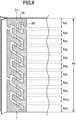
例えば、図7に示されている袋体のように横部分36の幅が縦部分38の幅より狭い構成、あるいは、図8に示されている袋体のように縦部分38の幅が横部分36の幅より狭い構成でもよい。さらに、図9に示されている袋体のように、縦部分38内において幅が変化している構成でもよい。このような構成でも、急激な体積変化に伴う酸素流入を効果的に防止することができる。
気室26の幅を異ならせる場合には、最も幅の広い部分と最も狭い部分の比率が1.2以上3以下、より好ましくは1.5以上2.5以下とすることが好ましい。
本願の図面においては、明確化のために、略矩形状の気室を構成の各波の形状、各波間のピッチ等は、模式化されて描かれている。
次に、本実施態様のコーヒー保存用の袋体の製造方法について説明する。まず、袋体の製造(帯状接合領域の形成)に使用する超音波接合機の構成について説明する。
袋体の帯状接合領域の形成には、超音波接合機が使用されるのが好ましい。超音波接合機は、50Hzまたは60Hzの商用電気を15~70KHz程度の高周波信号に変換する超音波発振機と、この信号を機械的振動に変換するコンバータと、この機械的振動を増幅するブースターと、増幅された振動を溶着対象に伝える円板状ホーン、ホーンとの間でフィルムの2つの端部を挟持する円板状アンビル等を備えている公知の構成の超音波接合機である。
ホーンとアンビルは、いずれも円板状であり、フィルムの2つの端部を挟持しながら回転し、重なったフィルムの2つの端部に帯状接合領域を連続的に形成する。なお、ホーンとアンビルは、図示しない駆動装置により回転駆動される。
図10は、超音波接合機で使用されるアンビル50の構成を示す模式的な斜視図である。アンビル50は、円板状の形状を有し、外周面52には、袋体の帯状接合領域の形状にする凸部54が形成されている。この凸部54には袋体の通気路24の平面形状に対応する溝56が形成されている。
凸部54の高さと溝56の深さは0.2mm以上1.0mm以下が好ましく、0.25mm以上0.8mm以下がより好ましく、0.3mm以上0.5mm以下が更に好ましい。
凸部54の高さと溝56の深さが0.2mm未満であると帯状接合領域部の接合強度が不充分になる場合があり、1.0mmを超えると縁部でフィルムが切れて、うまく接合できない場合がある。凸部54の高さと溝56の深さは同じでも、異なっていてもよい。
凸部54の高さと溝56の深さが0.2mm未満であると帯状接合領域部の接合強度が不充分になる場合があり、1.0mmを超えると縁部でフィルムが切れて、うまく接合できない場合がある。凸部54の高さと溝56の深さは同じでも、異なっていてもよい。
凸部54と溝56の断面形状は、長方形、かまぼこ型、台形が好ましいが、縁部でフィルムが切れてしまうことを防止する観点から、かまぼこ型、台形状が好ましい。
本実施態様の超音波接合機で使用されるホーンは円板状であり、平滑な外周面を有している。
ホーンとアンビルの直径は、50mmないし150mm程度である、またホーンとアンビルの外周面の幅は、帯状接合領の幅に対応して7mmないし25mm程度である。ホーンとアンビルの素材については公知のものが使用できるが、特にステンレスやチタン合金が好ましい。
ホーンとアンビルの外周面の縁部を面取りしてもよい。面取りをすることでこの部分でフィルムが切れてしまうことを防止することができる。また、ホーンとアンビルの側面には軽量化のための孔(肉抜き)が形成されていてもよい。
接合速度(駆動速度)は、5m/分以上50m/分以下程度が好ましく、150m/分以上45m/分以下がより好ましく、20m/分以上40m/分以下が更に好ましい。接合速度を5m/分以上とすることで、効率よい製造が可能になる。また接合速度が5m/分未満の場合、接合部分に過剰な熱がかかり、均一な幅の通気路を形成できないことがある。一方、接合速度を50m/分以下とすることで充分な接合強度を得ることが可能になる。
フィルムの端部を挟持する際、ホーンとアンビルの間には加圧装置により20Nないし500N程度の圧力がかけられる。
尚、外周面に凸部を持つアンビルと平滑な外周面を持つホーンを具備する超音波接合機について説明したが、別の実施形態として、平滑な外周面を持つアンビルと外周面に凸部を持つホーンを具備する超音波接合機を用いてもよい。
尚、外周面に凸部を持つアンビルと平滑な外周面を持つホーンを具備する超音波接合機について説明したが、別の実施形態として、平滑な外周面を持つアンビルと外周面に凸部を持つホーンを具備する超音波接合機を用いてもよい。
次に本実施態様のコーヒー保存用の袋体の製造方法について説明する。しかしながら、この製造方法はこれに限定されるものではない。
(1)バリアフィルムを準備する。
(2)このフィルムを2つに折り、この部分を円周面上に帯状接合領域に対応する凹凸を有する円板状アンビルと、平滑な円周面を持つ円板状ホーンを有する超音波接合機で接合して、帯状接合領域、気室、内部通気路と外部通気路、通気路を同時に形成する。この部分をサイドシール部または背貼り部とすることが好ましい。
(3)次にヒートシール等の方法でボトムシール部を形成する。
ボトムシール部を形成する時に、同時に気室の下側の封止部を形成することもできる。
(4)続いてヒートシール等の方法でトップシール部を形成する。
トップシール部を形成する時に、同時に気室の上側の封止部を形成することもできる。
(2)このフィルムを2つに折り、この部分を円周面上に帯状接合領域に対応する凹凸を有する円板状アンビルと、平滑な円周面を持つ円板状ホーンを有する超音波接合機で接合して、帯状接合領域、気室、内部通気路と外部通気路、通気路を同時に形成する。この部分をサイドシール部または背貼り部とすることが好ましい。
(3)次にヒートシール等の方法でボトムシール部を形成する。
ボトムシール部を形成する時に、同時に気室の下側の封止部を形成することもできる。
(4)続いてヒートシール等の方法でトップシール部を形成する。
トップシール部を形成する時に、同時に気室の上側の封止部を形成することもできる。
以上の説明は袋体を1つずつ作成する方法であるが、1枚のフィルムを用いて複数の袋体の帯状接合領域を連続して形成し、その後フィルムを切り離して複数の袋体としてもよい。この方法は袋体を非常に効率よく製造できるので好ましい。
本実施態様のコーヒー保存用袋体にコーヒーを充填する方法には特に制限はない。
例えば上記の方法で袋体を形成し、トップシール部を形成する前にコーヒーを充填し、次いで、トップシール部を形成する方法を用いることができる。
例えば上記の方法で袋体を形成し、トップシール部を形成する前にコーヒーを充填し、次いで、トップシール部を形成する方法を用いることができる。
なお、コーヒーを充填後、トップシール部を形成する前に袋体内にチッ素を充填することも好ましい。袋体内にチッ素を充填することにより、保存中のコーヒーの劣化をより効果的に抑制できる。
本発明の前記実施形態に限定されることなく、特許請求の範囲に記載された技術的思想の範囲内で種々の変更、変形が可能である。
以下、本発明の実施例を説明する。
(実施例1)
超音波接合機として、ホーンとアンビルが円板状で、アンビルの外周面には図8の形状の気室を持つ帯状接合領域に対応した凸部が形成されている超音波接合機を使用した。一方、ホーンの外周面は平滑である。
(実施例1)
超音波接合機として、ホーンとアンビルが円板状で、アンビルの外周面には図8の形状の気室を持つ帯状接合領域に対応した凸部が形成されている超音波接合機を使用した。一方、ホーンの外周面は平滑である。
幅30cm、長さ100cm、厚さ85μmのバリアフィルム(バリア層付きナイロンフィルム/低密度ポリエチレンの積層フィルム )を2つ折りにして、2つの端部を重ね合わせて超音波接合して帯状接合領域を形成した。
帯状接合領域の幅は10mmで、フィルムの長さ方向に沿って100cmにわたって形成した。
帯状接合領域の幅は10mmで、フィルムの長さ方向に沿って100cmにわたって形成した。
超音波接合機のホーンの発振振動数は20KHz、振動振幅は15μm、押しつけ圧は250N、接合速度は25m/分とした。
以上により、縦25cm、横15cmの袋体が縦方向に4つ連結した袋体の中間体を作成した。
この袋体の中間体の上端から25cmの部分を幅方向にヒートシールして、幅3mmのボトムシール部を形成し、同時に気室の下端部を封止した。
次にボトムシール部の下を幅方向に裁断して、縦25cm、横15cmの袋体とした。
その後、袋体にコーヒー豆(グァテマラ ピーベリー)を100g入れ、袋体内部をチッ素ガスで充填した。その直後にヒートシールにより幅3mmのトップシール部を形成し、袋体を閉鎖した。
その後、袋体にコーヒー豆(グァテマラ ピーベリー)を100g入れ、袋体内部をチッ素ガスで充填した。その直後にヒートシールにより幅3mmのトップシール部を形成し、袋体を閉鎖した。
以上により、コーヒー豆を収納した袋体を作成した。同様の方法で残りの袋体の中間体が3個のコーヒー豆を収納した袋体を作成した。
この袋体にはサイドシール部に本発明の帯状接合領域を有し、この部分に通気路が形成されている。通気路の個数は3であり、各通気路の長さは265mmである。また、各通気路には屈曲部が20個設けられていて、そのうち10個の折れ曲がり角度は80度で、他の10個は100度である。通気路の幅は2mmであるが、屈曲部分では幅が4mmとしてある。
この袋体にはサイドシール部に本発明の帯状接合領域を有し、この部分に通気路が形成されている。通気路の個数は3であり、各通気路の長さは265mmである。また、各通気路には屈曲部が20個設けられていて、そのうち10個の折れ曲がり角度は80度で、他の10個は100度である。通気路の幅は2mmであるが、屈曲部分では幅が4mmとしてある。
この状態で、コーヒーの保存を行なったところ80日間保存しても袋体の膨らみはなく、酸素濃度も3%以下であった。さらに、袋体を1.5mの高さからコンクリートの床に3回落下させても袋体の破損は無かった。またこの際、袋体内部に酸素が流入することも無かった。
(実施例2)
袋体の大きさを縦27cm、横15cmとすることと、通気路の形状を以下のように変える以外は実施例1と同様にして実施例2を実施した。
実施例1と同様の結果が得られた。気室の形状は図3のようにした。その他の形状は以下のとおりである。
・通気路の長さは260mm、通気路の数は3個である。
・通気路の幅:フィルムの端部に略平行な部分の幅は1.5mm、フィルムの端部に略垂直な部分の幅も1.5mmである。
・屈曲部の内角αは56度、内角βは124度である。
・各通気路の56度の角度を有する屈曲部の数は19個、124度の角度を有する屈曲部の数は19個である。
・Ad/Atの値は0.21である。
・気室の面積が1170mm2である。
・外部通気路、内部通気路の幅はともに1.2、通気路の幅の最も小さい部分の値と、前記外部通気路の幅の比の値は0.8である。
(実施例3)
通気路の形状を以下のように変える以外は下記のようにして実施例3を実施したところ、実施例1と同様の結果が得られた。気室の形状は図7のようにした。その他の形状は以下のとおりである。
・通気路の長さは260mm、通気路の数は3個である。
・通気路の幅:フィルムの端部に略平行な部分の幅は1.5mm、フィルムの端部に略垂直な部分の幅は3.0mmである。
・屈曲部の内角αは56度、内角βは124度である。
・各通気路の56度の角度を有する屈曲部の数は19個、124度の角度を有する屈曲部の数は19個である。
・Ad/Atの値は0.21である。
・気室の面積が1440mm2である。
・外部通気路、内部通気路の幅はともに1.2mm、通気路の幅の最も小さい部分の値と、前記外部通気路の幅の比の値は0.8である。
(実施例4)
通気路の形状を以下のように変える以外は下記のようにして実施例4を実施したところ、実施例1と同様の結果が得られた。気室の形状は図3のようにした。その他の形状は以下のとおりである。
・通気路の長さは390mm、通気路の数は1個である。
・通気路の幅:フィルムの端部に略平行な部分42の幅は1.5mm、フィルムの端部に略垂直な部分43の幅も1.5mmである。
・屈曲部の内角αは65度、内角βは115度である。
・通気路の65度の角度を有する屈曲部の数は29個、115度の角度を有する屈曲部の数は29個である。
・Ad/Atの値は0.21である。
・気室の面積が1170mm2である。
・外部通気路、内部通気路の幅はともに1.2mm、通気路の幅の最も小さい部分の値と、前記外部通気路の幅の比の値は0.8である。
10:袋体
12:フィルム
12a(フィルムの)側端部
16:帯状接合領域
22:内部空間
24:通気路
26:気室
28:内部通気路
30:外部通気路
32: (気室の)端部
34: (気室の)端部
36: (気室の)横部分
38: (気室の)縦部分
40:屈曲部
12:フィルム
12a(フィルムの)側端部
16:帯状接合領域
22:内部空間
24:通気路
26:気室
28:内部通気路
30:外部通気路
32: (気室の)端部
34: (気室の)端部
36: (気室の)横部分
38: (気室の)縦部分
40:屈曲部
Claims (13)
- 60g以上2000g以下のコーヒーを保存するためのコーヒー保存用袋体であって、
前記袋体は、バリアフィルムによって形成され、縦方向の長さが10cm以上60cm以下、横方向の長さが6cm以上40cm以下であり、
前記フィルムの2つの端部が互いに重ねられ接合されている帯状接合領域を備え、
前記帯状接合領域内に、前記フィルムを非接合とすることにより形成され前記フィルムの端部に沿って延び両端部分が封止された略矩形波形状の空間である気室と、前記気室と前記袋体の内部空間とを連通する内部通気路、前記気室と前記袋体の外部空間とを連通する外部通気路とが設けられ、
前記内部通気路と、該内部通気路に連通した前記気室の部分と、前記内部通気路に隣接し前記気室の部分に連通した外部通気路と、によって、前記袋体の内部と外部とを連通する通気路が構成され、
前記気室は、前記フィルムの端部に略平行に前記矩形波の延びる方向に延びる略直線状の横部分と、該横部分に対して40度以上120度以下の角度をなして前記袋体の内部空間と外部空間とを結ぶ方向に延びる縦部分と、前記横部分と縦部分との接合部となる屈曲部を有している、
ことを特徴とするコーヒー保存用袋体。 - 60g以上2000g以下のコーヒーを保存するためのコーヒー保存用袋体であって、
前記袋体は、バリアフィルムによって形成され、縦方向の長さが10cm以上60cm以下、横方向の長さが6cm以上40cm以下であり、
前記フィルムの2つの端部が互いに重ねられ接合されている帯状接合領域を備え、
前記帯状接合領域内に、前記フィルムを非接合とすることにより形成され前記フィルムの端部に沿って延び両端部分が封止された略矩形波形状の空間である気室と、前記気室と前記袋体の内部空間とを連通する内部通気路、前記気室と前記袋体の外部空間とを連通する外部通気路とが設けられ、
前記内部通気路と、該内部通気路に連通した前記気室の部分と、前記内部通気路に隣接し前記気室の部分に連通した外部通気路と、によって、前記袋体の内部と外部とを連通する通気路が構成され、
前記気室は、前記フィルムの端部に略平行に前記矩形波の延びる方向に延びる略直線状の横部分と、該横部分に対して所定角度をなして前記袋体の内部空間と外部空間とを結ぶ方向に延びる縦部分と、前記横部分と縦部分との接合部となる屈曲部とを有し、
一の前記横部分の一端において前記横部分と前記縦部分とがなす角度αと、前記一の横部分の他端において前記横部分と前記縦部分とがなす角度βとしたとき、α+βが150度以上240度以下となる、
ことを特徴とするコーヒー保存用袋体。 - 前記通気路が、1本以上12本以下、設けられている、
請求項1または2に記載のコーヒー保存用袋体。 - 前記気室の長さが200mm以上2400mm以下である、
請求項1または2に記載のコーヒー保存用袋体。 - 前記通気路において、最も幅の広い部分と最も狭い部分の幅の比率が1.2以上3以下である、
請求項1に記載のコーヒー保存用袋体。 - 1本の前記通気路に、15個以上90個以下の前記屈曲部が形成されている、
請求項1または2に記載のコーヒー保存用袋体。 - 前記内部通気路および外部通気路の幅が0.5mm以上3mm以下である、
請求項1または2に記載のコーヒー保存用袋体。 - 前記気室の幅と前記外部通気路の幅との比が0.4以上1.0未満である、
請求項1または2に記載のコーヒー保存用袋体。 - 前記気室は、前記縦部分が前記帯状接合領域の幅方向中央を延びる仮想直線Lcを横切って延びるように配置され、
前記気室の縦部分を通って延びる前記仮想直線の所定部分の長さをAt、長さAtの仮想直線のうち前記フィルムが接合されている部分の長さの合計をAdとき、Ad/Atが0.10以上0.75以下である、
請求項1または2に記載のコーヒー保存用袋体。 - 前記気室の平面視における総面積が75mm2以上2000mm2以下である、
請求項1または2に記載のコーヒー保存用袋体。 - 前記帯状接合領域が超音波接合部である、
請求項1または2に記載のコーヒー保存用袋体。 - 外周面上に前記帯状接合領域に対応する凹凸を有する円盤状アンビルと、平滑な円周面を持つ円盤状ホーンを有する超音波接合機を用いて請求項1または2に記載のコーヒー保存用袋体を製造することを特徴とするコーヒー保存用袋体の製造方法。
- 請求項1または2に記載のコーヒー保存用袋体に60g以上2000g以下のコーヒーを充填して保存する、コーヒーの保存方法。
Applications Claiming Priority (4)
| Application Number | Priority Date | Filing Date | Title |
|---|---|---|---|
| JP2022-077883 | 2022-05-11 | ||
| JP2022077883 | 2022-05-11 | ||
| JP2022120811A JP7249703B1 (ja) | 2022-05-11 | 2022-07-28 | コーヒー保存用袋体およびその製造方法 |
| JP2022-120811 | 2022-07-28 |
Publications (1)
| Publication Number | Publication Date |
|---|---|
| WO2023218768A1 true WO2023218768A1 (ja) | 2023-11-16 |
Family
ID=85772973
Family Applications (1)
| Application Number | Title | Priority Date | Filing Date |
|---|---|---|---|
| PCT/JP2023/011524 WO2023218768A1 (ja) | 2022-05-11 | 2023-03-23 | コーヒー保存用袋体およびその製造方法 |
Country Status (2)
| Country | Link |
|---|---|
| JP (2) | JP7249703B1 (ja) |
| WO (1) | WO2023218768A1 (ja) |
Citations (2)
| Publication number | Priority date | Publication date | Assignee | Title |
|---|---|---|---|---|
| JP2021075303A (ja) * | 2019-11-08 | 2021-05-20 | 株式会社W | 鮮度保持用袋体及びその製造方法 |
| JP7004359B1 (ja) * | 2021-04-28 | 2022-01-21 | 株式会社W | コーヒー保存用袋体およびコーヒー保存方法 |
-
2022
- 2022-07-28 JP JP2022120811A patent/JP7249703B1/ja active Active
-
2023
- 2023-03-13 JP JP2023038275A patent/JP2023168226A/ja active Pending
- 2023-03-23 WO PCT/JP2023/011524 patent/WO2023218768A1/ja unknown
Patent Citations (2)
| Publication number | Priority date | Publication date | Assignee | Title |
|---|---|---|---|---|
| JP2021075303A (ja) * | 2019-11-08 | 2021-05-20 | 株式会社W | 鮮度保持用袋体及びその製造方法 |
| JP7004359B1 (ja) * | 2021-04-28 | 2022-01-21 | 株式会社W | コーヒー保存用袋体およびコーヒー保存方法 |
Also Published As
| Publication number | Publication date |
|---|---|
| JP7249703B1 (ja) | 2023-03-31 |
| JP2023168226A (ja) | 2023-11-24 |
| JP2023168182A (ja) | 2023-11-24 |
Similar Documents
| Publication | Publication Date | Title |
|---|---|---|
| EP2308766B1 (en) | Flexible packaging bag having a non-return function nozzle, and liquid-substance filling/packaging structure | |
| EP1795454B1 (en) | Pillow packaging bag, pillow type packaging body, heat seal bar for pillow packaging machine, and pillow packaging machine | |
| US6991109B1 (en) | Vacuum sealable bag apparatus and method | |
| AU2003203457B2 (en) | Vacuum or modified atmosphere package for foods which tend to release liquids and/or gases | |
| US6403174B1 (en) | Element for the formation of bags for packing food products and not under vacuum | |
| WO2023218768A1 (ja) | コーヒー保存用袋体およびその製造方法 | |
| WO2022230945A1 (ja) | コーヒー保存用袋体およびコーヒー保存方法 | |
| JP2019131215A (ja) | 鮮度保持用包装材およびその製造方法 | |
| JP4451244B2 (ja) | 包装袋のシール方法、包装袋、包装袋のシール装置、および製袋装置 | |
| JP2021075303A (ja) | 鮮度保持用袋体及びその製造方法 | |
| JP2019199304A (ja) | ガゼット袋および内容物収納体 | |
| WO2021039717A1 (ja) | 鮮度保持用袋体の製造方法 | |
| WO2020009036A1 (ja) | 鮮度保持容器、鮮度保持容器構成用部材及びその製造方法 | |
| WO2019198809A1 (ja) | 鮮度保持用袋体およびその製造方法 | |
| JPS6333258A (ja) | 液体用可撓性容器 | |
| JP7561002B2 (ja) | ソフトカプセル用収容容器、及び、ソフトカプセル入り収容容器 | |
| JPH1170619A (ja) | 米穀類用包装袋 | |
| JP2004315055A (ja) | 易開封性包装袋及びその製造方法 | |
| JP7419800B2 (ja) | 包装容器 | |
| JP2020172281A (ja) | 鮮度保持用袋体およびその製造方法 | |
| JP2006298378A (ja) | 気泡性緩衝シート及び緩衝袋 | |
| JPH1179200A (ja) | 米穀類用包装袋 | |
| JP3765870B2 (ja) | 米穀類用包装袋 | |
| JP2005145460A (ja) | 網状補強層を有する包装材料を用いた包装袋、および該包装袋の製造方法 | |
| JP2000168798A (ja) | 粒状物包装用袋、及びその製造方法 |
Legal Events
| Date | Code | Title | Description |
|---|---|---|---|
| 121 | Ep: the epo has been informed by wipo that ep was designated in this application |
Ref document number: 23803251 Country of ref document: EP Kind code of ref document: A1 |