WO2023218757A1 - 天井搬送車 - Google Patents
天井搬送車 Download PDFInfo
- Publication number
- WO2023218757A1 WO2023218757A1 PCT/JP2023/010434 JP2023010434W WO2023218757A1 WO 2023218757 A1 WO2023218757 A1 WO 2023218757A1 JP 2023010434 W JP2023010434 W JP 2023010434W WO 2023218757 A1 WO2023218757 A1 WO 2023218757A1
- Authority
- WO
- WIPO (PCT)
- Prior art keywords
- guide block
- slide
- magnetic member
- unit
- lateral direction
- Prior art date
- Legal status (The legal status is an assumption and is not a legal conclusion. Google has not performed a legal analysis and makes no representation as to the accuracy of the status listed.)
- Ceased
Links
Images


Classifications
-
- B—PERFORMING OPERATIONS; TRANSPORTING
- B65—CONVEYING; PACKING; STORING; HANDLING THIN OR FILAMENTARY MATERIAL
- B65G—TRANSPORT OR STORAGE DEVICES, e.g. CONVEYORS FOR LOADING OR TIPPING, SHOP CONVEYOR SYSTEMS OR PNEUMATIC TUBE CONVEYORS
- B65G1/00—Storing articles, individually or in orderly arrangement, in warehouses or magazines
- B65G1/02—Storage devices
- B65G1/04—Storage devices mechanical
-
- H—ELECTRICITY
- H10—SEMICONDUCTOR DEVICES; ELECTRIC SOLID-STATE DEVICES NOT OTHERWISE PROVIDED FOR
- H10P—GENERIC PROCESSES OR APPARATUS FOR THE MANUFACTURE OR TREATMENT OF DEVICES COVERED BY CLASS H10
- H10P72/00—Handling or holding of wafers, substrates or devices during manufacture or treatment thereof
- H10P72/30—Handling or holding of wafers, substrates or devices during manufacture or treatment thereof for conveying, e.g. between different workstations
Definitions
- One aspect of the present invention relates to an overhead transport vehicle.
- Patent Document 1 describes an overhead transport vehicle that includes an elevator drive section (unit) that raises and lowers an elevator platform, and a lateral movement section (slide mechanism) that moves the elevator drive section laterally. There is.
- the slide portion when the unit is slid by the slide mechanism, the slide portion may be moved relative to the transport vehicle main body while being guided by a guide block.
- the sliding unit tilts depending on the amount of protrusion from the conveyance vehicle body. Further, the position of the guide block (the supporting state of the unit) at that time is not fixed, and as a result, there is a possibility that the angle at which the unit tilts changes each time the unit slides.
- one aspect of the present invention aims to provide an overhead transport vehicle that can suppress an angle change in which a unit slid by a slide mechanism is tilted more than expected.
- An overhead transport vehicle includes a slide mechanism that slides a unit including an article holding section that holds an article along a first direction perpendicular to a traveling direction, and the slide mechanism is attached to the transport vehicle main body. a slide portion that moves along the first direction; and a guide block that is provided between the carrier body and the slide portion and is slidable in the first direction with respect to the carrier body and the slide portion, respectively. and a guide block holding part that holds the position of the guide block so that the positional relationship between the guide block and either the conveyor body or the slide part is maintained when the slide part moves.
- the position in the first direction is uncertain
- the guide block it has been found that depending on the position in the first direction, the slide part tilts more than expected, and the tilt angle changes. Therefore, in one aspect of the present invention, when the sliding portion is moved, the positional relationship (hereinafter also simply referred to as “positional relationship”) between the guide block and either the carrier main body or the sliding portion is determined by holding the guide block. Maintained by the department. This makes it possible to prevent the slide portion from tilting more than expected. In other words, it is possible to suppress an angle change in which the unit slid by the slide mechanism is tilted more than expected.
- the guide block holding portion is provided on the guide block and includes a first magnetic member including a magnet or a magnetic material, and a first magnetic member provided on at least one of the transport vehicle main body and the slide portion.
- a second magnetic member including a magnet or a magnetic substance attracted to the first magnetic member may be included.
- the first magnetic member may be attracted to the second magnetic member through the gap or the protective member while maintaining the position of the guide block. In this case, since the first magnetic member and the second magnetic member do not come into direct contact with each other, it is possible to suppress their damage.
- a plurality of guide blocks are provided, and the guide block holding section moves at least one of the plurality of guide blocks in a direction away from another guide block adjacent to the guide block. It may be energized.
- the guide block includes a first guide block and a second guide block, and the guide block holding portion is configured to support at least one of the guided vehicle body and the sliding portion in the first direction.
- the position of the first guide block may be maintained at one end, and the position of the second guide block may be maintained at the other end of at least one of the carrier body and the slide portion in the first direction.
- the distance between the first guide block and the second guide block can be widened as much as possible. Therefore, it is possible to suppress the inclination of the sliding portion and the inclination of the slid unit.
- the slide mechanism is provided with another slide part that moves along the first direction with respect to the slide part, and between the slide part and the other slide part, and the slide mechanism and another guide block that is slidable along the first direction with respect to each of the sliding part and the other sliding part, and when the other sliding part moves, the sliding part and the other sliding part are connected to each other.
- it may have another guide block holding part that holds the position of the other guide block. In this case, it becomes possible to easily increase the sliding amount (stroke) of the sliding mechanism.
- the slide mechanism may slide the unit to both one side and the other side in the first direction.
- the position of the guide block in the first direction is often unstable, so the effect of maintaining the positional relationship with the guide block holding part and suppressing changes in the angle of inclination of the sliding part more than expected is significant. become.
- the ceiling transport vehicle 1 of the embodiment travels along a track 20 laid near the ceiling of a clean room where semiconductor devices are manufactured.
- the track 20 forms a travel path for the overhead transport vehicle 1.
- the overhead transport vehicle 1 transports a FOUP (Front Opening Unified Pod) (article) 200 containing a plurality of semiconductor wafers, and transports the FOUP 200 to a load port 300 or the like provided in a processing device that performs various processes on semiconductor wafers. Perform the transfer.
- FOUP Front Opening Unified Pod
- the ceiling transport vehicle 1 includes a frame unit 2, a traveling unit 3, a lateral unit (slide mechanism) 4, a theta unit 5, an elevating drive unit 6, a holding unit (article holding section) 7, and a transport vehicle controller 8. and.
- the frame unit 2 includes a center frame (vehicle main body) 15, a front frame 16, and a rear frame 17.
- the front frame 16 extends downward from the front end of the center frame 15 (the front side in the traveling direction of the ceiling transport vehicle 1).
- the rear frame 17 extends downward from the rear end of the center frame 15 (the rear side in the traveling direction of the ceiling transport vehicle 1).
- the traveling unit 3 is arranged above the center frame 15. For example, the traveling unit 3 travels along the track 20 by receiving power from a high-frequency current line laid along the track 20 in a non-contact manner.
- the lateral unit 4 is arranged below the center frame 15. The lateral unit 4 slides the theta unit 5, the lifting drive unit 6, and the holding unit 7 laterally with respect to the center frame 15.
- the lateral direction in which the lateral unit 4 slides the unit 9 (the first direction, the lateral direction, and the lateral direction perpendicular to the traveling direction of the ceiling transport vehicle 1) is also simply referred to as the lateral direction.
- the lateral unit 4 moves the unit 9 to both one side and the other side in the lateral direction (left direction and right direction in the figure) by the driving force of a drive mechanism (not shown, such as a drive motor, pulley, belt, etc.). Slide it.
- the theta unit 5 is arranged below the lateral unit 4.
- Theta unit 5 rotates the elevation drive unit 6 and the holding unit 7 in a horizontal plane.
- the elevating drive unit 6 is arranged below the theta unit 5.
- the lifting drive unit 6 moves the holding unit 7 up and down by feeding out and winding up a plurality of belts B connected to the holding unit 7.
- the holding unit 7 is arranged below the lifting drive unit 6.
- the holding unit 7 is provided so as to be movable up and down by the up/down drive unit 6.
- the holding unit 7 has a pair of grippers 12 that can be opened and closed in the horizontal direction.
- the holding unit 7 holds the flange 201 of the FOUP 200 using a pair of grippers 12 .
- the conveyance vehicle controller 8 is arranged on the center frame 15.
- the conveyance vehicle controller 8 is an electronic control unit composed of a CPU (Central Processing Unit), a ROM (Read Only Memory), a RAM (Random Access Memory), and the like.
- the carrier controller 8 controls each part of the ceiling carrier 1 .
- the carrier controller 8 may be composed of a plurality of electronic control units.
- the carrier controller 8 may be arranged on the front frame 16 or the like.
- the ceiling transport vehicle 1 configured as described above operates as follows, as an example.
- the ceiling carrier 1 that does not hold the FOUP 200 stops at a predetermined position above the load port 300. If the position of the holding unit 7 to be lowered at the stop position deviates from the predetermined position with respect to the load port 300 (FOUP 200 placed on the load port 300), the holding unit 7 is lowered by driving the lateral unit 4 and theta unit 5. Adjust the horizontal position and horizontal angle of 7.
- the lifting drive unit 6 lowers the holding unit 7, and the holding unit 7 holds the flange 201 of the FOUP 200 placed on the load port 300.
- the lifting drive unit 6 raises the holding unit 7 to the rising end, and the FOUP 200 is placed between the front frame 16 and the rear frame 17. Subsequently, the ceiling transport vehicle 1 holding the FOUP 200 starts traveling.
- the ceiling carrier 1 holding the FOUP 200 stops at a predetermined position above the load port 300. If the position of the holding unit 7 (FOUP 200) that is lowered at the stop position deviates from the predetermined position with respect to the load port 300, the horizontal position and horizontal angle of the holding unit are adjusted by driving the lateral unit 4 and theta unit 5. do. Subsequently, the lifting drive unit 6 lowers the holding unit 7 to place the FOUP 200 on the load port 300, and the holding unit 7 releases the holding of the flange 201 of the FOUP 200. Subsequently, the lifting drive unit 6 raises the holding unit 7 to the rising end. Subsequently, the ceiling transport vehicle 1 that does not hold the FOUP 200 starts traveling.
- the lateral unit 4 includes an upper slide section (slide section) 41, an upper guide block (guide block) 42, a lower slide section (other slide section) 43, and a lower guide block (other guide block). ) 44, an upper guide block holding part (guide block holding part) 45, and a lower guide block holding part (another guide block holding part) 48.
- the upper slide portion 41 moves laterally with respect to the center frame 15. As shown in FIGS. The upper slide portion 41 is configured to be movable to both one side and the other side in the lateral direction below the center frame 15.
- the upper guide block 42 is provided between the center frame 15 and the upper slide portion 41.
- the upper guide block 42 is slidable along the lateral direction relative to the center frame 15 and the upper slide portion 41, respectively.
- the upper guide block 42 is, for example, a linear motion guide (LM guide) block.
- LM guide linear motion guide
- An upper groove 42a that opens upward is formed in the upper part of the upper guide block 42.
- a first upper rail portion 15a provided at the lower part of the center frame 15 so as to protrude downward is slidably engaged with the upper groove 42a along the lateral direction.
- the upper groove 42a and the first upper rail portion 15a extend in the lateral direction.
- a lower groove 42b that opens downward is formed in the lower part of the upper guide block 42.
- a second upper rail part 41a provided at the upper part of the upper slide part 41 so as to protrude upward is slidably engaged with the lower groove 42b along the lateral direction.
- the lower groove 42b and the second upper rail portion 41a extend in the lateral direction.
- the upper guide block 42 includes a first upper guide block (first guide block) 42X and a second upper guide block (second guide block) 42Y.
- the upper guide block 42 as described above guides the movement of the upper slide portion 41 in the lateral direction.
- the upper guide block 42 restricts the movement of the upper slide portion 41 in the traveling direction of the ceiling transport vehicle 1 .
- the upper guide block 42 connects the center frame 15 and the upper slide portion 41 in the vertical direction.
- the upper guide block 42 is not fixed in the lateral direction and is freely movable in the lateral direction (the lateral position is undefined).
- the lower slide section 43 moves laterally with respect to the upper slide section 41.
- the lower slide section 43 is configured to be movable to both one side and the other side in the lateral direction below the upper slide section 41 .
- the theta unit 5 is connected to the lower slide portion 43.
- the lower guide block 44 is provided between the upper slide section 41 and the lower slide section 43.
- the lower guide block 44 is slidable along the lateral direction with respect to each of the upper slide section 41 and the lower slide section 43.
- the lower guide block 44 is, for example, a linear motion guide (LM guide) block.
- An upper groove 44a that opens upward is formed in the upper part of the lower guide block 44.
- a first lower rail part 41b provided at the lower part of the upper slide part 41 so as to protrude downward is slidably engaged with the upper groove 44a along the lateral direction.
- the upper groove 44a and the first lower rail portion 41b extend in the lateral direction.
- a lower groove 44b that opens downward is formed in the lower part of the lower guide block 44.
- a second lower rail part 43a provided at the upper part of the lower slide part 43 so as to protrude upward is slidably engaged with the lower groove 44b along the lateral direction.
- the lower groove 44b and the second lower rail portion 43a extend in the lateral direction.
- a plurality of lower guide blocks 44 are provided.
- the lower guide block 44 includes a first lower guide block 44X and a second lower guide block 44Y.
- the lower guide block 44 as described above guides the movement of the lower slide portion 43 in the lateral direction.
- the lower guide block 44 restricts the movement of the lower slide portion 43 in the traveling direction of the ceiling transport vehicle 1 .
- the lower guide block 44 connects the upper slide section 41 and the lower slide section 43 in the vertical direction.
- the lower guide block 44 is not fixed in the lateral direction and is freely movable in the lateral direction (the lateral position is undefined).
- the upper guide block holding section 45 maintains the position of the upper guide block 42 using magnetic force that attracts each other (in other words, attractive force or attractive force due to magnetic force).
- the upper guide block holding section 45 includes first magnetic members 46X and 46Y that include magnets or magnetic bodies, and second magnetic members 47A to 47D that include magnets or magnetic bodies that are attracted to the first magnetic members 46X and 46Y. .
- the first magnetic member 46X is provided on the outer side of the first upper guide block 42X in the lateral direction (on the opposite side to the second upper guide block 42Y side).
- the first magnetic member 46Y is provided on the outer side of the second upper guide block 42Y in the lateral direction (on the side opposite to the first upper guide block 42X side).
- the second magnetic member 47A is fixed to the center frame 15 via a stopper 61A.
- the stopper 61A is provided at the lower part of the center frame 15 on the outside of the first upper rail portion 15a in the lateral direction.
- the stopper 61A is arranged at one end of the center frame 15 in the lateral direction. The stopper 61A prevents the first upper guide block 42X from falling off from the first upper rail portion 15a by coming into contact with the first upper guide block 42X.
- the second magnetic member 47A is fixed to the lower surface of the stopper 61A.
- the second magnetic member 47A is disposed outwardly in the lateral direction from the stopper 61A.
- the inner surface in the lateral direction of the second magnetic member 47A is located on the outer side in the lateral direction than the inner surface in the lateral direction of the stopper 61A.
- the second magnetic member 47B is fixed to the upper slide portion 41 via a stopper 61B.
- the stopper 61B is provided on the upper side of the upper slide portion 41 and on the outer side of the second upper rail portion 41a in the lateral direction.
- the stopper 61B is arranged at one end of the upper slide portion 41 in the lateral direction. The stopper 61B prevents the first upper guide block 42X from falling off from the second upper rail portion 41a by coming into contact with the first upper guide block 42X.
- the second magnetic member 47B is fixed to the top surface of the stopper 61B.
- the second magnetic member 47B is disposed outwardly in the lateral direction from the stopper 61B.
- the inner surface in the lateral direction of the second magnetic member 47B is located on the outer side in the lateral direction than the inner surface in the lateral direction of the stopper 61B.
- the second magnetic member 47C is fixed to the lower surface of the stopper 61C.
- the second magnetic member 47C is disposed outwardly in the lateral direction from the stopper 61C.
- the inner surface in the lateral direction of the second magnetic member 47C is located on the outer side in the lateral direction than the inner surface in the lateral direction of the stopper 61C.
- the second magnetic member 47D is fixed to the upper slide portion 41 via a stopper 61D.
- the stopper 61D is provided at the upper part of the upper slide section 41 on the outside of the second upper rail section 41a in the lateral direction.
- the stopper 61D is arranged at the other end of the upper slide portion 41 in the lateral direction.
- the stopper 61D prevents the second upper guide block 42Y from falling off from the second upper rail portion 41a by coming into contact with the second upper guide block 42Y.
- the second magnetic member 47D is fixed to the top surface of the stopper 61D.
- the second magnetic member 47D is disposed outwardly in the lateral direction from the stopper 61D.
- the inner surface in the lateral direction of the second magnetic member 47D is located on the outer side in the lateral direction than the inner surface in the lateral direction of the stopper 61D.
- the lower guide block holding section 48 holds the lower guide block 44 so that the positional relationship between either the upper slide section 41 or the lower slide section 43 and the lower guide block 44 is maintained when the lower slide section 43 moves. hold the position.
- the lower guide block holding section 48 urges the first lower guide block 44X and the second lower guide block 44Y in a direction in which they move away from each other.
- the lower guide block holding section 48 holds the position of the first lower guide block 44X at one end side of the upper slide section 41 and the lower slide section 43 in the lateral direction, and holds the position of the first lower guide block 44X at one end side of the upper slide section 41 and the lower slide section 43 in the lateral direction.
- the position of the second lower guide block 44Y is held at the other end.
- the lower guide block holding section 48 holds the position of the lower guide block 44 by using magnetic force that attracts each other.
- the lower guide block holding section 48 includes first magnetic members 49X, 49Y that include magnets or magnetic bodies, and second magnetic members 50A to 50D that include magnets or magnetic bodies that are attracted to the first magnetic members 49X, 49Y. .
- the first magnetic member 49X is provided on the outer side of the first lower guide block 44X in the lateral direction (on the opposite side to the second lower guide block 44Y side).
- the first magnetic member 49Y is provided on the outer side of the second lower guide block 44Y in the lateral direction (on the side opposite to the first lower guide block 44X side).
- the second magnetic member 50A is fixed to the upper slide portion 41 via a stopper 62A.
- the stopper 62A is provided at the lower part of the upper slide section 41 on the outside of the first lower rail section 41b in the lateral direction.
- the stopper 62A is arranged at one end of the upper slide portion 41 in the lateral direction.
- the stopper 62A prevents the first lower guide block 44X from falling off from the first lower rail portion 41b by coming into contact with the first lower guide block 44X.
- the second magnetic member 50A is fixed to the lower surface of the stopper 62A.
- the second magnetic member 50A is disposed outwardly in the lateral direction from the stopper 62A.
- the inner surface of the second magnetic member 50A in the lateral direction is located on the outer side in the lateral direction than the inner surface of the stopper 62A in the lateral direction.
- the second magnetic member 50B is fixed to the lower slide portion 43 via a stopper 62B.
- the stopper 62B is provided on the upper side of the lower slide section 43 and on the outer side of the second upper rail section 43b in the lateral direction.
- the stopper 62B is arranged at one end of the lower slide portion 43 in the lateral direction.
- the stopper 62B prevents the first lower guide block 44X from falling off from the second lower rail portion 43a by coming into contact with the first lower guide block 44X.
- the second magnetic member 50B is fixed to the top surface of the stopper 62B.
- the second magnetic member 50B is disposed outwardly in the lateral direction from the stopper 62B.
- the inner surface in the lateral direction of the second magnetic member 50B is located on the outer side in the lateral direction than the inner surface in the lateral direction of the stopper 62B.
- the second magnetic member 50C is fixed to the upper slide portion 41 via a stopper 62C.
- the stopper 62C is provided at the lower part of the upper slide section 41 and on the outer side of the first lower rail section 41b in the lateral direction.
- the stopper 62C is arranged at the other end of the upper slide portion 41 in the lateral direction.
- the stopper 62C prevents the second lower guide block 44Y from falling off from the first lower rail portion 41b by coming into contact with the second lower guide block 44Y.
- the second magnetic member 50C is fixed to the lower surface of the stopper 62C.
- the second magnetic member 50C is disposed outwardly in the lateral direction from the stopper 62C.
- the inner surface in the lateral direction of the second magnetic member 50C is located on the outer side in the lateral direction than the inner surface in the lateral direction of the stopper 62C.
- the second magnetic member 50D is fixed to the lower slide portion 43 via a stopper 62D.
- the stopper 62D is provided on the upper side of the lower slide portion 43 and on the outer side of the second lower rail portion 43a in the lateral direction.
- the stopper 62D is arranged at the other end of the lower slide portion 43 in the lateral direction.
- the stopper 62D prevents the second lower guide block 44Y from falling off from the second lower rail portion 43a by coming into contact with the second lower guide block 44Y.
- the second magnetic member 50D is fixed to the top surface of the stopper 62D.
- the second magnetic member 50D is disposed outwardly in the lateral direction from the stopper 62D.
- the inner surface of the second magnetic member 47D in the lateral direction is located on the outer side in the lateral direction than the inner surface of the stopper 62D in the lateral direction.
- the upper slide portion 41 is moved to the other side in the lateral direction with respect to the center frame 15 while being guided by the upper guide block 42 due to the driving force of the drive mechanism (not shown).
- the lower slide section 43 further slides to the other side in the lateral direction with respect to the upper slide section 41 while being guided by the lower guide block 44 due to the driving force of a drive mechanism (not shown).
- the first upper guide block 42X slides along the first upper rail part 15a as the upper slide part 41 moves. At this time, the first upper guide block 42X remains located at one end of the upper slide portion 41 because the first magnetic member 46X is attracted by the magnetic force of the second magnetic member 47B. Further, the second upper guide block 42Y slides along the second upper rail section 41a as the upper slide section 41 moves. At this time, the second upper guide block 42Y remains located on the other end side of the center frame 15 because the first magnetic member 46Y is attracted by the magnetic force of the second magnetic member 47C.
- the first lower guide block 44X slides along the first lower rail part 41b as the lower slide part 43 moves.
- the first lower guide block 44X remains located at one end of the lower slide portion 43 because the first magnetic member 49X is attracted by the magnetic force of the second magnetic member 50B.
- the second lower guide block 44Y slides along the second lower rail part 43a as the lower slide part 43 moves.
- the first magnetic member 49Y is attracted by the magnetic force of the second magnetic member 50C, and the second lower guide block 44Y remains located on the other end side of the upper slide portion 41.
- the ceiling transport vehicle 1 it is possible to suppress an angle change in which the unit 9 slid by the lateral unit 4 is tilted more than expected. It becomes possible to suppress variations in the inclination of the unit 9.
- the lateral unit 4 allows the unit 9 to slide as expected. It is possible to reduce shaking, improve transfer stability (transfer accuracy, etc.), and suppress the amount of deviation of various mounted sensors.
- the upper guide block holding section 45 includes first magnetic members 46X, 46Y provided on the upper guide block 42, and second magnetic members 47A to 47D provided on the center frame 15 and the upper slide section 41. and, including.
- the first magnetic members 46X, 46Y and the second magnetic members 47A to 47D are used as the upper guide block holding section 45 to suppress the angle change in which the unit 9 slid by the lateral unit 4 is tilted more than expected. becomes possible.
- the lower guide block holding section 48 has first magnetic members 49X and 49Y provided on the lower guide block 44, and second magnetic members provided on the upper slide section 41 and the lower slide section 43. members 50A to 50D.
- the first magnetic members 49X, 49Y and the second magnetic members 50A to 50D are used as the lower guide block holding portion 48 to suppress an angle change in which the unit 9 slid by the lateral unit 4 is tilted more than expected. becomes possible.
- the first magnetic members 46X, 46Y are attracted to the second magnetic members 47A to 47D through the gaps while maintaining the position of the upper guide block 42.
- the first magnetic members 49X, 49Y are attracted to the second magnetic members 50A to 50D through the gaps while maintaining the position of the lower guide block 44.
- the first magnetic members 46X, 46Y, 49X, 49Y and the second magnetic members 47A to 47D, 50A to 50D do not come into direct contact with each other, damage to these members can be suppressed.
- a plurality of upper guide blocks 42 are provided (configured to be divided).
- the upper guide block holding section 45 urges the first upper guide block 42X and the second upper guide block 42Y in a direction away from each other. That is, at least one of the plurality of upper guide blocks 42 is urged in a direction away from other upper guide blocks 42 adjacent to the upper guide block 42 .
- a plurality of lower guide blocks 44 are provided (configured to be divided).
- the lower guide block holding portion 48 urges the first lower guide block 44X and the second lower guide block 44Y in a direction away from each other.
- at least one of the plurality of lower guide blocks 44 is urged in a direction away from other lower guide blocks 44 adjacent to the lower guide block 44 .
- the upper guide block holding section 45 holds the position of the first upper guide block 42X at one end side of the center frame 15 and the upper slide section 41 in the lateral direction, and The position of the second upper guide block 42Y is maintained at the other end side of the upper slide section 41. Thereby, the distance between the first upper guide block 42X and the second upper guide block 42Y can be widened as much as possible.
- the first upper guide block 42X and the second upper guide block 42Y can be positioned at the most advantageous positions. Therefore, it becomes possible to suppress the inclination of the upper slide portion 41 and the inclination of the slid unit 9.
- the lower guide block holding section 48 holds the position of the first lower guide block 44X at one end side of the upper slide section 41 and the lower slide section 43 in the lateral direction, and The position of the second lower guide block 44Y is maintained at the other end side of the upper slide section 41 and the lower slide section 43. Thereby, the interval between the first lower guide block 44X and the second lower guide block 44Y can be widened as much as possible.
- the first lower guide block 44X and the second lower guide block 44Y can be positioned at the most advantageous position. Therefore, the lower slide portion 43 can suppress inclination, and the slid unit 9 can suppress inclination.
- the lateral unit 4 includes a lower slide portion 43, a lower guide block 44, and a lower guide block holder 48 in addition to an upper slide portion 41, an upper guide block 42, and an upper guide block holder 45.
- a plurality of upper guide blocks 42 are provided, including a first upper guide block 42X and a second upper guide block 42Y, but the number of upper guide blocks 42 is not limited and may be one. There may be three or more. Similarly, the number of lower guide blocks 44 is not limited either, and may be one, three or more.
- the lateral unit 104 may include one undivided upper guide block 142 and one undivided lower guide block 144.
- the upper guide block 142 and the lower guide block 144 have a shape that is elongated in the lateral direction (for example, a shape in which the longitudinal dimension is twice or more the transverse dimension).
- the stoppers 61C, 61D, 62C, 62D and the second magnetic members 47C, 47D, 50C, 50D may not be provided.
- the first magnetic members 46X, 46Y are attracted to the second magnetic members 47A to 47D through the gaps, but the present invention is not limited thereto.
- the first magnetic members 46X, 46Y may be attracted to the second magnetic members 47A-47D, for example, via a protective member that protects the second magnetic members 47A-47D.
- the first magnetic members 49X, 49Y are attracted to the second magnetic members 50A to 50D through gaps, but the present invention is not limited thereto.
- the first magnetic members 49X, 49Y may be attracted to the second magnetic members 50A to 50D, for example, via a protective member that protects the second magnetic members 50A to 50D.
- the protective member is not particularly limited, and various known members may be used.
- the upper guide block holding part 45 and the lower guide block holding part 48 hold the positions of the upper guide block 42 and the lower guide block 44 using magnetic force, but the present invention is not limited thereto.
- the upper guide block holding section 45 and the lower guide block holding section 48 may hold the positions of the upper guide block 42 and the lower guide block 44 using the elastic force of an elastic body such as a spring.
- the guide block holding part is a first magnetic member provided on the guide block and including a magnet or a magnetic body;
- the overhead conveyance vehicle according to invention 1 further comprising: a second magnetic member that is provided on at least one of the conveyance vehicle body and the slide portion and includes a magnet or a magnetic body that is attracted to the first magnetic member.
- a plurality of guide blocks are provided, The ceiling according to any one of inventions 1 to 3, wherein the guide block holding section urges at least one of the plurality of guide blocks in a direction away from another guide block adjacent to the guide block.
- the guide block includes a first guide block and a second guide block, The guide block holding part is maintaining the position of the first guide block at one end side of at least one of the carrier body and the slide portion in the first direction;
- the ceiling conveyance vehicle according to invention 4 wherein the position of the second guide block is maintained at the other end side of at least one of the conveyance vehicle body and the slide portion in the first direction.
- the slide mechanism is another slide part that moves along the first direction with respect to the slide part; another guide block provided between the slide part and the other slide part and slidable along the first direction with respect to each of the slide part and the other slide part; Maintaining the position of the other guide block so that the positional relationship between either the slide part or the other slide part and the other guide block is maintained when the other slide part moves.
Landscapes
- Engineering & Computer Science (AREA)
- Mechanical Engineering (AREA)
- Warehouses Or Storage Devices (AREA)
- Carriers, Traveling Bodies, And Overhead Traveling Cranes (AREA)
Abstract
天井搬送車は、物品を保持する物品保持部を含むユニットを、走行方向と直交する第1方向に沿ってスライドさせるスライド機構を備える。スライド機構は、搬送車本体に対して第1方向に沿って移動するスライド部と、搬送車本体とスライド部との間に設けられ、搬送車本体及びスライド部のそれぞれに対して第1方向に沿って摺動可能なガイドブロックと、スライド部の移動の際に搬送車本体及びスライド部の何れか一方とガイドブロックとの位置関係が保たれるように、ガイドブロックの位置を保持するガイドブロック保持部と、を有する。
Description
本発明の一側面は、天井搬送車に関する。
例えば、特許文献1には、昇降台を昇降させる昇降駆動部(ユニット)と、昇降駆動部を横方向に横移動させる横移動部(スライド機構)と、を備えた天井搬送車が記載されている。
上述した天井搬送車では、スライド機構によりユニットをスライドさせる際、搬送車本体に対してスライド部をガイドブロックによりガイドさせながら移動させる場合がある。このような天井搬送車では、搬送車本体からの突出量に応じてスライドさせたユニットが傾く。また、そのときのガイドブロックの位置(ユニットの支持状態)は定まっておらず、その結果、ユニットの傾く角度が当該スライドの都度変化するおそれがある。
そこで、本発明の一側面は、スライド機構によりスライドさせたユニットが想定以上に傾く角度変化を抑制することが可能な天井搬送車を提供することを目的とする。
本発明の一側面に係る天井搬送車は、物品を保持する物品保持部を含むユニットを、走行方向と直交する第1方向に沿ってスライドさせるスライド機構を備え、スライド機構は、搬送車本体に対して第1方向に沿って移動するスライド部と、搬送車本体とスライド部との間に設けられ、搬送車本体及びスライド部のそれぞれに対して第1方向に沿って摺動可能なガイドブロックと、スライド部の移動の際に搬送車本体及びスライド部の何れか一方とガイドブロックとの位置関係が保たれるように、ガイドブロックの位置を保持するガイドブロック保持部と、を有する。
本発明者は鋭意検討を重ねた結果、天井搬送車においてスライド機構によりユニットをスライドさせる際、ガイドブロックが第1方向に自由に移動できる(第1方向の位置が不定である)場合、ガイドブロックの第1方向の位置によっては、スライド部が想定以上に大きく傾き、傾く角度が変化するという知見を得た。そこで、本発明の一側面では、スライド部の移動の際に、搬送車本体及びスライド部の何れか一方とガイドブロックとの位置関係(以下、単に「位置関係」ともいう)を、ガイドブロック保持部により保っている。これにより、スライド部が想定以上に大きく傾くのを抑えることが可能となる。すなわち、スライド機構によりスライドさせたユニットが想定以上に傾く角度変化を抑制することが可能となる。
本発明の一側面に係る天井搬送車では、ガイドブロック保持部は、ガイドブロックに設けられ、磁石又は磁性体を含む第1磁性部材と、搬送車本体及びスライド部の少なくとも一方に設けられ、第1磁性部材に引き付けられる磁石又は磁性体を含む第2磁性部材と、を含んでいてもよい。この場合、第1磁性部材及び第2磁性部材をガイドブロック保持部として利用して、スライド機構によりスライドさせたユニットが想定以上に傾く角度変化を抑制することが可能となる。
本発明の一側面に係る天井搬送車では、第1磁性部材は、ガイドブロックの位置を保持している状態において、隙間又は保護部材を介して第2磁性部材に引き付けられてもよい。この場合、第1磁性部材と第2磁性部材とが直接接触しないことから、これらの損傷を抑えることが可能となる。
本発明の一側面に係る天井搬送車では、ガイドブロックは、複数設けられ、ガイドブロック保持部は、複数のガイドブロックの少なくとも何れかを、当該ガイドブロックに隣接する他のガイドブロックから離れる方向に付勢してもよい。これにより、複数のガイドブロックが設けられた場合において、複数のガイドブロックの少なくとも何れかの位置関係を効果的に保つことが可能となる。
本発明の一側面に係る天井搬送車では、ガイドブロックは、第1ガイドブロックと第2ガイドブロックとを含み、ガイドブロック保持部は、第1方向における搬送車本体及びスライド部の少なくとも何れかの一端側にて、第1ガイドブロックの位置を保持し、第1方向における搬送車本体及びスライド部の少なくとも何れかの他端側にて、第2ガイドブロックの位置を保持してもよい。この場合、第1ガイドブロックと第2ガイドブロックとの間隔を可能な限り広げることができる。よって、スライド部の傾きを抑制し、スライドさせたユニットの傾きを抑制することが可能となる。
本発明の一側面に係る天井搬送車では、スライド機構は、スライド部に対して第1方向に沿って移動する他のスライド部と、スライド部と他のスライド部との間に設けられ、スライド部と他のスライド部のそれぞれに対して第1方向に沿って摺動可能な他のガイドブロックと、他のスライド部の移動の際にスライド部及び他のスライド部の何れか一方と他のガイドブロックとの位置関係が保たれるように、他のガイドブロックの位置を保持する他のガイドブロック保持部と、を有していてもよい。この場合、スライド機構のスライド量(ストローク)を容易に大きくすることが可能となる。
本発明の一側面に係る天井搬送車では、スライド機構は、ユニットを第1方向における一方側と他方側との双方にスライドさせてもよい。このような構成では、ガイドブロックは第1方向の位置が不定である場合が多いことから、位置関係をガイドブロック保持部により保ってスライド部が想定以上に傾く角度の変化を抑えるという効果は顕著になる。
本発明の一側面によれば、スライド機構によりスライドさせたユニットが想定以上に傾く角度変化を抑制することが可能な天井搬送車を提供することが可能となる。
以下、図面を参照して、一実施形態について詳細に説明する。図面の説明において、同一要素には同一符号を付し、重複する説明を省略する。「上」及び「下」の語は、鉛直方向の上下方向に対応する。
図1に示されるように、実施形態の天井搬送車1は、半導体デバイスが製造されるクリーンルームの天井付近に敷設された軌道20に沿って走行する。軌道20は、天井搬送車1の走行路を形成する。天井搬送車1は、複数の半導体ウェハが収容されたFOUP(Front Opening Unified Pod)(物品)200の搬送、及び、半導体ウェハに各種処理を施す処理装置に設けられたロードポート300等に対するFOUP200の移載を行う。
天井搬送車1は、フレームユニット2と、走行ユニット3と、ラテラルユニット(スライド機構)4と、シータユニット5と、昇降駆動ユニット6と、保持ユニット(物品保持部)7と、搬送車コントローラ8と、を備える。フレームユニット2は、センターフレーム(搬送車本体)15と、フロントフレーム16と、リアフレーム17と、を有している。フロントフレーム16は、センターフレーム15における前側(天井搬送車1の走行方向における前側)の端部から下側に延在している。リアフレーム17は、センターフレーム15における後側(天井搬送車1の走行方向における後側)の端部から下側に延在している。
走行ユニット3は、センターフレーム15の上側に配置されている。走行ユニット3は、例えば、軌道20に沿って敷設された高周波電流線から非接触で電力の供給を受けることで、軌道20に沿って走行する。ラテラルユニット4は、センターフレーム15の下側に配置されている。ラテラルユニット4は、シータユニット5、昇降駆動ユニット6及び保持ユニット7を、センターフレーム15に対して側方向へスライドさせる。
なお、シータユニット5、昇降駆動ユニット6及び保持ユニット7を、単にユニット9とも称する。ラテラルユニット4がユニット9をスライドさせる側方向(天井搬送車1の走行方向と直交する第1方向,横方向,側方)を、単に側方とも称する。ラテラルユニット4は、ユニット9を側方向における一方側と他方側との双方(図中の左方向及び右方向)に、不図示の駆動機構(例えば駆動モータ、プーリ及びベルト等)の駆動力によりスライドさせる。
シータユニット5は、ラテラルユニット4の下側に配置されている。シータユニット5は、昇降駆動ユニット6及び保持ユニット7を水平面内において回動させる。昇降駆動ユニット6は、シータユニット5の下側に配置されている。昇降駆動ユニット6は、保持ユニット7に接続された複数のベルトBの繰出し及び巻取りにより、保持ユニット7を昇降させる。保持ユニット7は、昇降駆動ユニット6の下側に配置されている。保持ユニット7は、昇降駆動ユニット6により昇降可能に設けられている。保持ユニット7は、水平方向に沿って開閉可能な一対のグリッパ12を有している。保持ユニット7は、一対のグリッパ12によりFOUP200のフランジ201を保持する。
搬送車コントローラ8は、センターフレーム15に配置されている。搬送車コントローラ8は、CPU(Central Processing Unit)、ROM(Read only memory)及びRAM(Random access memory)等によって構成された電子制御ユニットである。搬送車コントローラ8は、天井搬送車1の各部を制御する。搬送車コントローラ8は、複数の電子制御ユニットにより構成されていてもよい。また、搬送車コントローラ8は、フロントフレーム16等に配置されていてもよい。
以上のように構成された天井搬送車1は、一例として、次のように動作する。ロードポート300から天井搬送車1にFOUP200を移載する場合には、FOUP200を保持していない天井搬送車1がロードポート300の上方の予め定められた位置に停止する。停止位置において下降させる保持ユニット7の位置が、ロードポート300(ロードポート300に載置されたFOUP200)に対する所定位置からずれる場合には、ラテラルユニット4及びシータユニット5を駆動することにより、保持ユニット7の水平位置及び水平角度を調整する。続いて、昇降駆動ユニット6が保持ユニット7を下降させ、保持ユニット7が、ロードポート300に載置されているFOUP200のフランジ201を保持する。続いて、昇降駆動ユニット6が保持ユニット7を上昇端まで上昇させて、フロントフレーム16とリアフレーム17との間にFOUP200を配置する。続いて、FOUP200を保持した天井搬送車1が走行を開始する。
一方、天井搬送車1からロードポート300にFOUP200を移載する場合には、FOUP200を保持した天井搬送車1がロードポート300の上方の予め定められた位置に停止する。停止位置において下降させる保持ユニット7(FOUP200)の位置が、ロードポート300に対する所定位置からずれる場合には、ラテラルユニット4及びシータユニット5を駆動することにより、保持ユニットの水平位置及び水平角度を調整する。続いて、昇降駆動ユニット6が保持ユニット7を下降させ、ロードポート300にFOUP200を載置し、保持ユニット7がFOUP200のフランジ201の保持を解放する。続いて、昇降駆動ユニット6が保持ユニット7を上昇端まで上昇させる。続いて、FOUP200を保持していない天井搬送車1が走行を開始する。
次に、ラテラルユニット4の構成について、説明する。
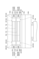
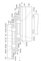
図2に示されるように、ラテラルユニット4は、上段スライド部(スライド部)41、上段ガイドブロック(ガイドブロック)42、下段スライド部(他のスライド部)43、下段ガイドブロック(他のガイドブロック)44、上段ガイドブロック保持部(ガイドブロック保持部)45、及び、下段ガイドブロック保持部(他のガイドブロック保持部)48を有する。
[上段スライド部]
図2及び図3(a)に示されるように、上段スライド部41は、センターフレーム15に対して側方向に沿って移動する。上段スライド部41は、センターフレーム15の下方において、側方向の一方側及び他方側の双方に移動可能に構成されている。
図2及び図3(a)に示されるように、上段スライド部41は、センターフレーム15に対して側方向に沿って移動する。上段スライド部41は、センターフレーム15の下方において、側方向の一方側及び他方側の双方に移動可能に構成されている。
[上段ガイドブロック]
上段ガイドブロック42は、センターフレーム15と上段スライド部41との間に設けられている。上段ガイドブロック42は、センターフレーム15及び上段スライド部41のそれぞれに対して、側方向に沿って摺動可能である。上段ガイドブロック42は、例えばリニアモーションガイド(LMガイド)ブロックである。
上段ガイドブロック42は、センターフレーム15と上段スライド部41との間に設けられている。上段ガイドブロック42は、センターフレーム15及び上段スライド部41のそれぞれに対して、側方向に沿って摺動可能である。上段ガイドブロック42は、例えばリニアモーションガイド(LMガイド)ブロックである。
上段ガイドブロック42の上部には、上方に開口する上溝42aが形成されている。上溝42aには、センターフレーム15の下部に下方へ突出するように設けられた第1上段レール部15aが、側方向に沿って摺動可能に係合している。上溝42a及び第1上段レール部15aは、側方向に沿って延在する。上段ガイドブロック42の下部には、下方に開口する下溝42bが形成されている。下溝42bには、上段スライド部41の上部に上方へ突出するように設けられた第2上段レール部41aが、側方向に沿って摺動可能に係合している。下溝42b及び第2上段レール部41aは、側方向に沿って延在する。
上段ガイドブロック42は、複数設けられている。ここでは、上段ガイドブロック42は、第1上段ガイドブロック(第1ガイドブロック)42Xと第2上段ガイドブロック(第2ガイドブロック)42Yとを含む。以上のような上段ガイドブロック42は、側方向における上段スライド部41の移動をガイドする。上段ガイドブロック42は、天井搬送車1の走行方向における上段スライド部41の移動を規制する。上段ガイドブロック42は、上下方向においてセンターフレーム15と上段スライド部41とを連結する。上段ガイドブロック42は、側方向において固定されておらず、側方向に自由に移動可能(側方向の位置が不定)である。
[下段スライド部]
図2及び図3(b)に示されるように、下段スライド部43は、上段スライド部41に対して側方向に沿って移動する。下段スライド部43は、上段スライド部41の下方において、側方向の一方側及び他方側の双方に移動可能に構成されている。下段スライド部43には、シータユニット5が連結されている。
図2及び図3(b)に示されるように、下段スライド部43は、上段スライド部41に対して側方向に沿って移動する。下段スライド部43は、上段スライド部41の下方において、側方向の一方側及び他方側の双方に移動可能に構成されている。下段スライド部43には、シータユニット5が連結されている。
[下段ガイドブロック]
下段ガイドブロック44は、上段スライド部41と下段スライド部43との間に設けられている。下段ガイドブロック44は、上段スライド部41及び下段スライド部43のそれぞれに対して、側方向に沿って摺動可能である。下段ガイドブロック44は、例えばリニアモーションガイド(LMガイド)ブロックである。
下段ガイドブロック44は、上段スライド部41と下段スライド部43との間に設けられている。下段ガイドブロック44は、上段スライド部41及び下段スライド部43のそれぞれに対して、側方向に沿って摺動可能である。下段ガイドブロック44は、例えばリニアモーションガイド(LMガイド)ブロックである。
下段ガイドブロック44の上部には、上方に開口する上溝44aが形成されている。上溝44aには、上段スライド部41の下部に下方へ突出するように設けられた第1下段レール部41bが、側方向に沿って摺動可能に係合している。上溝44a及び第1下段レール部41bは、側方向に沿って延在する。下段ガイドブロック44の下部には、下方に開口する下溝44bが形成されている。下溝44bには、下段スライド部43の上部に上方へ突出するように設けられた第2下段レール部43aが、側方向に沿って摺動可能に係合している。下溝44b及び第2下段レール部43aは、側方向に沿って延在する。
下段ガイドブロック44は、複数設けられている。ここでは、下段ガイドブロック44は、第1下段ガイドブロック44Xと第2下段ガイドブロック44Yとを含む。以上のような下段ガイドブロック44は、側方向における下段スライド部43の移動をガイドする。下段ガイドブロック44は、天井搬送車1の走行方向における下段スライド部43の移動を規制する。下段ガイドブロック44は、上下方向において上段スライド部41と下段スライド部43とを連結する。下段ガイドブロック44は、側方向において固定されておらず、側方向に自由に移動可能(側方向の位置が不定)である。
[上段ガイドブロック保持部]
上段ガイドブロック保持部45は、上段スライド部41の移動の際にセンターフレーム15及び上段スライド部41の何れか一方と上段ガイドブロック42との位置関係が保たれるように、上段ガイドブロック42の位置を保持する。上段ガイドブロック保持部45は、第1上段ガイドブロック42X及び第2上段ガイドブロック42Yを、これらが互いに離れる方向に付勢する。上段ガイドブロック保持部45は、側方向におけるセンターフレーム15及び上段スライド部41の一端側にて、第1上段ガイドブロック42Xの位置を保持し、側方向におけるセンターフレーム15及び上段スライド部41の他端側にて、第2上段ガイドブロック42Yの位置を保持する。
上段ガイドブロック保持部45は、上段スライド部41の移動の際にセンターフレーム15及び上段スライド部41の何れか一方と上段ガイドブロック42との位置関係が保たれるように、上段ガイドブロック42の位置を保持する。上段ガイドブロック保持部45は、第1上段ガイドブロック42X及び第2上段ガイドブロック42Yを、これらが互いに離れる方向に付勢する。上段ガイドブロック保持部45は、側方向におけるセンターフレーム15及び上段スライド部41の一端側にて、第1上段ガイドブロック42Xの位置を保持し、側方向におけるセンターフレーム15及び上段スライド部41の他端側にて、第2上段ガイドブロック42Yの位置を保持する。
上段ガイドブロック保持部45は、引き付け合う磁力(換言すると、磁力による引力又は誘引力)を利用して、上段ガイドブロック42の位置を保持する。上段ガイドブロック保持部45は、磁石又は磁性体を含む第1磁性部材46X,46Yと、第1磁性部材46X,46Yに引き付けられる磁石又は磁性体を含む第2磁性部材47A~47Dと、を有する。第1磁性部材46Xは、第1上段ガイドブロック42Xの側方向における外側(第2上段ガイドブロック42Y側とは反対側)に設けられている。第1磁性部材46Yは、第2上段ガイドブロック42Yの側方向における外側(第1上段ガイドブロック42X側とは反対側)に設けられている。
第2磁性部材47Aは、センターフレーム15にストッパ61Aを介して固定されている。ストッパ61Aは、センターフレーム15の下部において第1上段レール部15aの側方向の外側に設けられている。ストッパ61Aは、センターフレーム15の側方向の一端部に配置されている。ストッパ61Aは、第1上段ガイドブロック42Xに当たることで、第1上段レール部15aからの第1上段ガイドブロック42Xの脱落を防止する。
第2磁性部材47Aは、ストッパ61Aの下面に固定されている。第2磁性部材47Aは、ストッパ61Aよりも側方向における外側にズレて配置されている。換言すると、第2磁性部材47Aの側方向における内側の面は、ストッパ61Aの側方向における内側の面よりも、側方向の外側に位置する。これにより、第1上段ガイドブロック42Xがストッパ61Aに当たった場合において、第2磁性部材47Aと第1上段ガイドブロック42Xとの間には隙間が形成され、これらの直接的な接触が防止される。その結果、第1磁性部材46Xは、第1上段ガイドブロック42Xの位置を保持している状態において、隙間を介して第2磁性部材47Aに磁力により引き付けられる。
第2磁性部材47Bは、上段スライド部41にストッパ61Bを介して固定されている。ストッパ61Bは、上段スライド部41の上部において第2上段レール部41aの側方向の外側に設けられている。ストッパ61Bは、上段スライド部41の側方向の一端部に配置されている。ストッパ61Bは、第1上段ガイドブロック42Xに当たることで、第2上段レール部41aからの第1上段ガイドブロック42Xの脱落を防止する。
第2磁性部材47Bは、ストッパ61Bの上面に固定されている。第2磁性部材47Bは、ストッパ61Bよりも側方向における外側にズレて配置されている。換言すると、第2磁性部材47Bの側方向における内側の面は、ストッパ61Bの側方向における内側の面よりも、側方向の外側に位置する。これにより、第1上段ガイドブロック42Xがストッパ61Bに当たった場合において、第2磁性部材47Bと第1上段ガイドブロック42Xとの間には隙間が形成され、これらの直接的な接触が防止される。その結果、第1磁性部材46Xは、第1上段ガイドブロック42Xの位置を保持している状態において、隙間を介して第2磁性部材47Bに磁力により引き付けられる。
第2磁性部材47Cは、センターフレーム15にストッパ61Cを介して固定されている。ストッパ61Cは、センターフレーム15の下部において第1上段レール部15aの側方向の外側に設けられている。ストッパ61Cは、センターフレーム15の側方向の他端部に配置されている。ストッパ61Cは、第2上段ガイドブロック42Yに当たることで、第1上段レール部15aからの第2上段ガイドブロック42Yの脱落を防止する。
第2磁性部材47Cは、ストッパ61Cの下面に固定されている。第2磁性部材47Cは、ストッパ61Cよりも側方向における外側にズレて配置されている。換言すると、第2磁性部材47Cの側方向における内側の面は、ストッパ61Cの側方向における内側の面よりも、側方向の外側に位置する。これにより、第2上段ガイドブロック42Yがストッパ61Cに当たった場合において、第2磁性部材47Cと第2上段ガイドブロック42Yとの間には隙間が形成され、これらの直接的な接触が防止される。その結果、第1磁性部材46Yは、第2上段ガイドブロック42Yの位置を保持している状態において、隙間を介して第2磁性部材47Cに磁力により引き付けられる。
第2磁性部材47Dは、上段スライド部41にストッパ61Dを介して固定されている。ストッパ61Dは、上段スライド部41の上部において第2上段レール部41aの側方向の外側に設けられている。ストッパ61Dは、上段スライド部41の側方向の他端部に配置されている。ストッパ61Dは、第2上段ガイドブロック42Yに当たることで、第2上段レール部41aからの第2上段ガイドブロック42Yの脱落を防止する。
第2磁性部材47Dは、ストッパ61Dの上面に固定されている。第2磁性部材47Dは、ストッパ61Dよりも側方向における外側にズレて配置されている。換言すると、第2磁性部材47Dの側方向における内側の面は、ストッパ61Dの側方向における内側の面よりも、側方向の外側に位置する。これにより、第2上段ガイドブロック42Yがストッパ61Dに当たった場合において、第2磁性部材47Dと第2上段ガイドブロック42Yとの間には隙間が形成され、これらの直接的な接触が防止される。その結果、第1磁性部材46Yは、第2上段ガイドブロック42Yの位置を保持している状態において、隙間を介して第2磁性部材47Dに磁力により引き付けられる。
[下段ガイドブロック保持部]
下段ガイドブロック保持部48は、下段スライド部43の移動の際に上段スライド部41及び下段スライド部43の何れか一方と下段ガイドブロック44との位置関係が保たれるように、下段ガイドブロック44の位置を保持する。下段ガイドブロック保持部48は、第1下段ガイドブロック44X及び第2下段ガイドブロック44Yを、これらが互いに離れる方向に付勢する。下段ガイドブロック保持部48は、側方向における上段スライド部41及び下段スライド部43の一端側にて、第1下段ガイドブロック44Xの位置を保持し、側方向における上段スライド部41及び下段スライド部43の他端側にて、第2下段ガイドブロック44Yの位置を保持する。
下段ガイドブロック保持部48は、下段スライド部43の移動の際に上段スライド部41及び下段スライド部43の何れか一方と下段ガイドブロック44との位置関係が保たれるように、下段ガイドブロック44の位置を保持する。下段ガイドブロック保持部48は、第1下段ガイドブロック44X及び第2下段ガイドブロック44Yを、これらが互いに離れる方向に付勢する。下段ガイドブロック保持部48は、側方向における上段スライド部41及び下段スライド部43の一端側にて、第1下段ガイドブロック44Xの位置を保持し、側方向における上段スライド部41及び下段スライド部43の他端側にて、第2下段ガイドブロック44Yの位置を保持する。
下段ガイドブロック保持部48は、引き付け合う磁力を利用して、下段ガイドブロック44の位置を保持する。下段ガイドブロック保持部48は、磁石又は磁性体を含む第1磁性部材49X,49Yと、第1磁性部材49X,49Yに引き付けられる磁石又は磁性体を含む第2磁性部材50A~50Dと、を有する。第1磁性部材49Xは、第1下段ガイドブロック44Xの側方向における外側(第2下段ガイドブロック44Y側とは反対側)に設けられている。第1磁性部材49Yは、第2下段ガイドブロック44Yの側方向における外側(第1下段ガイドブロック44X側とは反対側)に設けられている。
第2磁性部材50Aは、上段スライド部41にストッパ62Aを介して固定されている。ストッパ62Aは、上段スライド部41の下部において第1下段レール部41bの側方向の外側に設けられている。ストッパ62Aは、上段スライド部41の側方向の一端部に配置されている。ストッパ62Aは、第1下段ガイドブロック44Xに当たることで、第1下段レール部41bからの第1下段ガイドブロック44Xの脱落を防止する。第2磁性部材50Aは、ストッパ62Aの下面に固定されている。第2磁性部材50Aは、ストッパ62Aよりも側方向における外側にズレて配置されている。換言すると、第2磁性部材50Aの側方向における内側の面は、ストッパ62Aの側方向における内側の面よりも、側方向の外側に位置する。これにより、第1下段ガイドブロック44Xがストッパ62Aに当たった場合において、第2磁性部材50Aと第1下段ガイドブロック44Xとの間には隙間が形成され、これらの直接的な接触が防止される。その結果、第1磁性部材49Xは、第1下段ガイドブロック44Xの位置を保持している状態において、隙間を介して第2磁性部材50Aに磁力により引き付けられる。
第2磁性部材50Bは、下段スライド部43にストッパ62Bを介して固定されている。ストッパ62Bは、下段スライド部43の上部において第2上段レール部43bの側方向の外側に設けられている。ストッパ62Bは、下段スライド部43の側方向の一端部に配置されている。ストッパ62Bは、第1下段ガイドブロック44Xに当たることで、第2下段レール部43aからの第1下段ガイドブロック44Xの脱落を防止する。第2磁性部材50Bは、ストッパ62Bの上面に固定されている。第2磁性部材50Bは、ストッパ62Bよりも側方向における外側にズレて配置されている。換言すると、第2磁性部材50Bの側方向における内側の面は、ストッパ62Bの側方向における内側の面よりも、側方向の外側に位置する。これにより、第1下段ガイドブロック44Xがストッパ62Bに当たった場合において、第2磁性部材50Bと第1下段ガイドブロック44Xとの間には隙間が形成され、これらの直接的な接触が防止される。その結果、第1磁性部材49Xは、第1下段ガイドブロック44Xの位置を保持している状態において、隙間を介して第2磁性部材50Bに磁力により引き付けられる。
第2磁性部材50Cは、上段スライド部41にストッパ62Cを介して固定されている。ストッパ62Cは、上段スライド部41の下部において第1下段レール部41bの側方向の外側に設けられている。ストッパ62Cは、上段スライド部41の側方向の他端部に配置されている。ストッパ62Cは、第2下段ガイドブロック44Yに当たることで、第1下段レール部41bからの第2下段ガイドブロック44Yの脱落を防止する。第2磁性部材50Cは、ストッパ62Cの下面に固定されている。第2磁性部材50Cは、ストッパ62Cよりも側方向における外側にズレて配置されている。換言すると、第2磁性部材50Cの側方向における内側の面は、ストッパ62Cの側方向における内側の面よりも、側方向の外側に位置する。これにより、第2下段ガイドブロック44Yがストッパ62Cに当たった場合において、第2磁性部材50Cと第2下段ガイドブロック44Yとの間には隙間が形成され、これらの直接的な接触が防止される。その結果、第1磁性部材49Yは、第2下段ガイドブロック44Yの位置を保持している状態において、隙間を介して第2磁性部材50Cに磁力により引き付けられる。
第2磁性部材50Dは、下段スライド部43にストッパ62Dを介して固定されている。ストッパ62Dは、下段スライド部43の上部において第2下段レール部43aの側方向の外側に設けられている。ストッパ62Dは、下段スライド部43の側方向の他端部に配置されている。ストッパ62Dは、第2下段ガイドブロック44Yに当たることで、第2下段レール部43aからの第2下段ガイドブロック44Yの脱落を防止する。第2磁性部材50Dは、ストッパ62Dの上面に固定されている。第2磁性部材50Dは、ストッパ62Dよりも側方向における外側にズレて配置されている。換言すると、第2磁性部材47Dの側方向における内側の面は、ストッパ62Dの側方向における内側の面よりも、側方向の外側に位置する。これにより、第2下段ガイドブロック44Yがストッパ62Dに当たった場合において、第2磁性部材50Dと第2下段ガイドブロック44Yとの間には隙間が形成され、これらの直接的な接触が防止される。その結果、第1磁性部材49Yは、第2下段ガイドブロック44Yの位置を保持している状態において、隙間を介して第2磁性部材50Dに磁力により引き付けられる。
次に、ラテラルユニット4の動作例について、説明する。
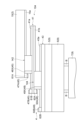
例えば図4に示されるように、ラテラルユニット4では、不図示の駆動機構の駆動力により、センターフレーム15に対して上段スライド部41が、上段ガイドブロック42によりガイドされながら側方向の他方側にスライドする。これと共に、不図示の駆動機構の駆動力により、上段スライド部41に対して下段スライド部43が、下段ガイドブロック44によりガイドされながら側方向の他方側に更にスライドする。
この場合、第1上段ガイドブロック42Xは、上段スライド部41の移動に連れ立って第1上段レール部15aに沿って摺動する。このとき、第1上段ガイドブロック42Xは、第1磁性部材46Xが第2磁性部材47Bにより磁力により引き付けられ、上段スライド部41の一端側に位置したままとなる。また、第2上段ガイドブロック42Yは、上段スライド部41の移動に連れ立って第2上段レール部41aに沿って摺動する。このとき、第2上段ガイドブロック42Yは、第1磁性部材46Yが第2磁性部材47Cにより磁力により引き付けられ、センターフレーム15の他端側に位置したままとなる。
またこの場合、第1下段ガイドブロック44Xは、下段スライド部43の移動に連れ立って第1下段レール部41bに沿って摺動する。このとき、第1下段ガイドブロック44Xは、第1磁性部材49Xが第2磁性部材50Bにより磁力により引き付けられ、下段スライド部43の一端側に位置したままとなる。第2下段ガイドブロック44Yは、下段スライド部43の移動に連れ立って第2下段レール部43aに沿って摺動する。このとき、第2下段ガイドブロック44Yは、第1磁性部材49Yが第2磁性部材50Cにより磁力により引き付けられ、上段スライド部41の他端側に位置したままとなる。
なお、ここでの動作例では、上段スライド部41及び下段スライド部43が側方向における他方側にスライドする場合を説明したが、側方向における一方側にスライドする場合も同様である。
以上、天井搬送車1では、上段スライド部41の移動の際に、センターフレーム15及び上段スライド部41の何れか一方と上段ガイドブロック42との位置関係を、上段ガイドブロック保持部45により保っている。これにより、上段スライド部41が傾く角度の予期せぬ変化を抑えることが可能となる。同様に、下段スライド部43の移動の際に、上段スライド部41及び下段スライド部43の何れか一方と下段ガイドブロック44との位置関係を、下段ガイドブロック保持部48により保っている。これにより、下段スライド部43が傾く角度の予期せぬ変化を抑えることが可能となる。
したがって、天井搬送車1によれば、ラテラルユニット4によりスライドさせたユニット9が想定以上に傾く角度変化を抑制することが可能となる。ユニット9の傾きのバラツキを抑制することが可能となる。ラテラルユニット4により想定どおりにユニット9をスライドさせることが可能となる。揺れの低下、移載安定性(移載精度等)の向上、及び、搭載されている各種のセンサのずれ量の抑制が可能となる。
天井搬送車1では、上段ガイドブロック保持部45は、上段ガイドブロック42に設けられた第1磁性部材46X,46Yと、センターフレーム15及び上段スライド部41に設けられた第2磁性部材47A~47Dと、を含む。この場合、第1磁性部材46X,46Y及び第2磁性部材47A~47Dを上段ガイドブロック保持部45として利用して、ラテラルユニット4によりスライドさせたユニット9が想定以上に傾く角度変化を抑制することが可能となる。
同様に、天井搬送車1では、下段ガイドブロック保持部48は、下段ガイドブロック44に設けられた第1磁性部材49X,49Yと、上段スライド部41及び下段スライド部43に設けられた第2磁性部材50A~50Dと、を含む。この場合、第1磁性部材49X,49Y及び第2磁性部材50A~50Dを下段ガイドブロック保持部48として利用して、ラテラルユニット4によりスライドさせたユニット9が想定以上に傾く角度変化を抑制することが可能となる。
天井搬送車1では、第1磁性部材46X,46Yは、上段ガイドブロック42の位置を保持している状態において、隙間を介して第2磁性部材47A~47Dに引き付けられる。第1磁性部材49X,49Yは、下段ガイドブロック44の位置を保持している状態において、隙間を介して第2磁性部材50A~50Dに引き付けられる。この場合、第1磁性部材46X,46Y,49X,49Yと第2磁性部材47A~47D,50A~50Dとが直接接触しないことから、これらの損傷を抑えることが可能となる。
天井搬送車1では、上段ガイドブロック42は、複数設けられている(分轄するように構成されている)。上段ガイドブロック保持部45は、第1上段ガイドブロック42Xと第2上段ガイドブロック42Yとを互いに離れる方向に付勢する。つまり、複数の上段ガイドブロック42の少なくとも何れかを、当該上段ガイドブロック42に隣接する他の上段ガイドブロック42から離れる方向に付勢する。これにより、複数の上段ガイドブロック42が設けられた場合において、これらの位置関係を効果的に保つことが可能となる。
同様に、天井搬送車1では、下段ガイドブロック44は、複数設けられている(分轄するように構成されている)。下段ガイドブロック保持部48は、第1下段ガイドブロック44Xと第2下段ガイドブロック44Yとを互いに離れる方向に付勢する。つまり、複数の下段ガイドブロック44の少なくとも何れかを、当該下段ガイドブロック44に隣接する他の下段ガイドブロック44から離れる方向に付勢する。これにより、複数の下段ガイドブロック44が設けられた場合において、これらの位置関係を効果的に保つことが可能となる。
天井搬送車1では、上段ガイドブロック保持部45は、側方向におけるセンターフレーム15及び上段スライド部41の一端側にて、第1上段ガイドブロック42Xの位置を保持し、側方向におけるセンターフレーム15及び上段スライド部41の他端側にて、第2上段ガイドブロック42Yの位置を保持する。これにより、第1上段ガイドブロック42Xと第2上段ガイドブロック42Yとの間隔を、可能な限り広げることができる。ラテラルユニット4によりユニット9をスライドさせる際、最も有利な位置に第1上段ガイドブロック42X及び第2上段ガイドブロック42Yを位置させることができる。よって、上段スライド部41の傾きを抑制し、スライドさせたユニット9の傾きを抑制することが可能となる。
同様に、天井搬送車1では、下段ガイドブロック保持部48は、側方向における上段スライド部41及び下段スライド部43の一端側にて、第1下段ガイドブロック44Xの位置を保持し、側方向における上段スライド部41及び下段スライド部43の他端側にて、第2下段ガイドブロック44Yの位置を保持する。これにより、第1下段ガイドブロック44Xと第2下段ガイドブロック44Yとの間隔を可能な限り広げることができる。ラテラルユニット4によりユニット9をスライドさせる際、最も有利な位置に第1下段ガイドブロック44X及び第2下段ガイドブロック44Yを位置させることができる。よって、下段スライド部43が傾きを抑制し、スライドさせたユニット9が傾きを抑制することが可能となる。
天井搬送車1では、ラテラルユニット4は、上段スライド部41、上段ガイドブロック42及び上段ガイドブロック保持部45に加え、下段スライド部43、下段ガイドブロック44及び下段ガイドブロック保持部48を有する。このように上下に複数段の構成を採用することにより、ラテラルユニット4のスライド量(ストローク)を容易に大きくすることが可能となる。
天井搬送車1では、ラテラルユニット4は、ユニット9を側方向における一方側と他方側との双方にスライドさせる。このような構成では、上段ガイドブロック42及び下段ガイドブロック44は側方向の位置が不定であることから、位置関係を上段ガイドブロック保持部45及び下段ガイドブロック保持部48により保って上段スライド部41及び下段スライド部43が想定以上に傾く角度の変化を抑えるという効果は顕著になる。
以上、一実施形態について説明したが、本発明の一側面は、上記実施形態に限られない。発明の一側面の趣旨を逸脱しない範囲で種々の変更が可能である。
上記実施形態では、上段ガイドブロック42が複数設けられており、第1上段ガイドブロック42X及び第2上段ガイドブロック42Yが含まれるが、上段ガイドブロック42の数は限定されず、1つであってもよいし、3つ以上であってもよい。同様に、下段ガイドブロック44の数も限定されず、1つであってもよいし、3つ以上であってもよい。例えば図5に示されるように、変形例に係るラテラルユニット104では、分割されていない1つの上段ガイドブロック142が設けられ、分割されていない1つの下段ガイドブロック144が設けられていてもよい。上段ガイドブロック142及び下段ガイドブロック144は、側方向に長尺の形状(例えば長手方向の寸法が短手方向の寸法の2倍以上の形状)を呈する。この場合、図示するように、ストッパ61C,61D,62C,62D及び第2磁性部材47C,47D,50C,50Dは設けられていなくてもよい。
上記実施形態又は変形例では、第1磁性部材46X,46Yは、隙間を介して第2磁性部材47A~47Dに引き付けられるが、これに限定されない。第1磁性部材46X,46Yは、例えば第2磁性部材47A~47Dを保護する保護部材を介して、第2磁性部材47A~47Dに引き付けられてもよい。同様に、第1磁性部材49X,49Yは、隙間を介して第2磁性部材50A~50Dに引き付けられるが、これに限定されない。第1磁性部材49X,49Yは、例えば第2磁性部材50A~50Dを保護する保護部材を介して、第2磁性部材50A~50Dに引き付けられてもよい。この場合、第1磁性部材46X,46Y,49X,49Yと第2磁性部材47A~47D,50A~50Dとが直接接触しないことから、これらの損傷を抑えることが可能となる。保護部材は特に限定されず、種々の公知部材を用いてもよい。
上記実施形態又は変形例では、上段ガイドブロック保持部45及び下段ガイドブロック保持部48は、磁力を利用して上段ガイドブロック42及び下段ガイドブロック44の位置を保持したが、これに限定されない。上段ガイドブロック保持部45及び下段ガイドブロック保持部48は、バネ等の弾性体の弾性力を利用して上段ガイドブロック42及び下段ガイドブロック44の位置を保持してもよい。
上記実施形態又は変形例における各構成には、上述した材料及び形状に限定されず、様々な材料及び形状を適用することができる。上記実施形態又は変形例における各構成は、他の実施形態又は変形例における各構成に任意に適用することができる。上記実施形態又は変形例における各構成の一部は、本発明の一態様の要旨を逸脱しない範囲で適宜に省略可能である。
なお、以下、本発明の一態様の構成要件を記載する。
<発明1>
物品を保持する物品保持部を含むユニットを、走行方向と直交する第1方向に沿ってスライドさせるスライド機構を備え、
前記スライド機構は、
搬送車本体に対して前記第1方向に沿って移動するスライド部と、
前記搬送車本体と前記スライド部との間に設けられ、前記搬送車本体及び前記スライド部のそれぞれに対して前記第1方向に沿って摺動可能なガイドブロックと、
前記スライド部の移動の際に前記搬送車本体及び前記スライド部の何れか一方と前記ガイドブロックとの位置関係が保たれるように、前記ガイドブロックの位置を保持するガイドブロック保持部と、を有する、天井搬送車。
<発明2>
前記ガイドブロック保持部は、
前記ガイドブロックに設けられ、磁石又は磁性体を含む第1磁性部材と、
前記搬送車本体及び前記スライド部の少なくとも一方に設けられ、前記第1磁性部材に引き付けられる磁石又は磁性体を含む第2磁性部材と、を含む、発明1に記載の天井搬送車。
<発明3>
前記第1磁性部材は、前記ガイドブロックの位置を保持している状態において、隙間又は保護部材を介して前記第2磁性部材に引き付けられる、発明2に記載の天井搬送車。
<発明4>
前記ガイドブロックは、複数設けられ、
前記ガイドブロック保持部は、複数の前記ガイドブロックの少なくとも何れかを、当該ガイドブロックに隣接する他の前記ガイドブロックから離れる方向に付勢する、発明1~3の何れか一項に記載の天井搬送車。
<発明5>
前記ガイドブロックは、第1ガイドブロックと第2ガイドブロックとを含み、
前記ガイドブロック保持部は、
前記第1方向における前記搬送車本体及び前記スライド部の少なくとも何れかの一端側にて、前記第1ガイドブロックの位置を保持し、
前記第1方向における前記搬送車本体及び前記スライド部の少なくとも何れかの他端側にて、前記第2ガイドブロックの位置を保持する、発明4に記載の天井搬送車。
<発明6>
前記スライド機構は、
前記スライド部に対して前記第1方向に沿って移動する他のスライド部と、
前記スライド部と前記他のスライド部との間に設けられ、前記スライド部と前記他のスライド部のそれぞれに対して前記第1方向に沿って摺動可能な他のガイドブロックと、
前記他のスライド部の移動の際に前記スライド部及び前記他のスライド部の何れか一方と前記他のガイドブロックとの位置関係が保たれるように、前記他のガイドブロックの位置を保持する他のガイドブロック保持部と、を有する、発明1~5の何れか一項に記載の天井搬送車。
<発明7>
前記スライド機構は、前記ユニットを前記第1方向における一方側と他方側との双方にスライドさせる、発明1~6の何れか一項に記載の天井搬送車。
<発明1>
物品を保持する物品保持部を含むユニットを、走行方向と直交する第1方向に沿ってスライドさせるスライド機構を備え、
前記スライド機構は、
搬送車本体に対して前記第1方向に沿って移動するスライド部と、
前記搬送車本体と前記スライド部との間に設けられ、前記搬送車本体及び前記スライド部のそれぞれに対して前記第1方向に沿って摺動可能なガイドブロックと、
前記スライド部の移動の際に前記搬送車本体及び前記スライド部の何れか一方と前記ガイドブロックとの位置関係が保たれるように、前記ガイドブロックの位置を保持するガイドブロック保持部と、を有する、天井搬送車。
<発明2>
前記ガイドブロック保持部は、
前記ガイドブロックに設けられ、磁石又は磁性体を含む第1磁性部材と、
前記搬送車本体及び前記スライド部の少なくとも一方に設けられ、前記第1磁性部材に引き付けられる磁石又は磁性体を含む第2磁性部材と、を含む、発明1に記載の天井搬送車。
<発明3>
前記第1磁性部材は、前記ガイドブロックの位置を保持している状態において、隙間又は保護部材を介して前記第2磁性部材に引き付けられる、発明2に記載の天井搬送車。
<発明4>
前記ガイドブロックは、複数設けられ、
前記ガイドブロック保持部は、複数の前記ガイドブロックの少なくとも何れかを、当該ガイドブロックに隣接する他の前記ガイドブロックから離れる方向に付勢する、発明1~3の何れか一項に記載の天井搬送車。
<発明5>
前記ガイドブロックは、第1ガイドブロックと第2ガイドブロックとを含み、
前記ガイドブロック保持部は、
前記第1方向における前記搬送車本体及び前記スライド部の少なくとも何れかの一端側にて、前記第1ガイドブロックの位置を保持し、
前記第1方向における前記搬送車本体及び前記スライド部の少なくとも何れかの他端側にて、前記第2ガイドブロックの位置を保持する、発明4に記載の天井搬送車。
<発明6>
前記スライド機構は、
前記スライド部に対して前記第1方向に沿って移動する他のスライド部と、
前記スライド部と前記他のスライド部との間に設けられ、前記スライド部と前記他のスライド部のそれぞれに対して前記第1方向に沿って摺動可能な他のガイドブロックと、
前記他のスライド部の移動の際に前記スライド部及び前記他のスライド部の何れか一方と前記他のガイドブロックとの位置関係が保たれるように、前記他のガイドブロックの位置を保持する他のガイドブロック保持部と、を有する、発明1~5の何れか一項に記載の天井搬送車。
<発明7>
前記スライド機構は、前記ユニットを前記第1方向における一方側と他方側との双方にスライドさせる、発明1~6の何れか一項に記載の天井搬送車。
1…天井搬送車、4,104…ラテラルユニット(スライド機構)、7…保持ユニット(物品保持部)、9…ユニット、15…センターフレーム(搬送車本体)、41…上段スライド部(スライド部)、42,142…上段ガイドブロック(ガイドブロック)、42X…第1上段ガイドブロック(第1ガイドブロック)、42Y…第2上段ガイドブロック(第2ガイドブロック)、43…下段スライド部(他のスライド部)、44,144…下段ガイドブロック(他のガイドブロック)、44X…第1下段ガイドブロック、44Y…第2下段ガイドブロック、45…上段ガイドブロック保持部(ガイドブロック保持部)、46X,46Y,49X,49Y…第1磁性部材、47A,47B,47C,47D,50A,50B,50C,50D…第2磁性部材、48…下段ガイドブロック保持部(他のガイドブロック保持部)、200…FOUP(物品)。
Claims (7)
- 物品を保持する物品保持部を含むユニットを、走行方向と直交する第1方向に沿ってスライドさせるスライド機構を備え、
前記スライド機構は、
搬送車本体に対して前記第1方向に沿って移動するスライド部と、
前記搬送車本体と前記スライド部との間に設けられ、前記搬送車本体及び前記スライド部のそれぞれに対して前記第1方向に沿って摺動可能なガイドブロックと、
前記スライド部の移動の際に前記搬送車本体及び前記スライド部の何れか一方と前記ガイドブロックとの位置関係が保たれるように、前記ガイドブロックの位置を保持するガイドブロック保持部と、を有する、天井搬送車。 - 前記ガイドブロック保持部は、
前記ガイドブロックに設けられ、磁石又は磁性体を含む第1磁性部材と、
前記搬送車本体及び前記スライド部の少なくとも一方に設けられ、前記第1磁性部材に引き付けられる磁石又は磁性体を含む第2磁性部材と、を含む、請求項1に記載の天井搬送車。 - 前記第1磁性部材は、前記ガイドブロックの位置を保持している状態において、隙間又は保護部材を介して前記第2磁性部材に引き付けられる、請求項2に記載の天井搬送車。
- 前記ガイドブロックは、複数設けられ、
前記ガイドブロック保持部は、複数の前記ガイドブロックの少なくとも何れかを、当該ガイドブロックに隣接する他の前記ガイドブロックから離れる方向に付勢する、請求項1に記載の天井搬送車。 - 前記ガイドブロックは、第1ガイドブロックと第2ガイドブロックとを含み、
前記ガイドブロック保持部は、
前記第1方向における前記搬送車本体及び前記スライド部の少なくとも何れかの一端側にて、前記第1ガイドブロックの位置を保持し、
前記第1方向における前記搬送車本体及び前記スライド部の少なくとも何れかの他端側にて、前記第2ガイドブロックの位置を保持する、請求項4に記載の天井搬送車。 - 前記スライド機構は、
前記スライド部に対して前記第1方向に沿って移動する他のスライド部と、
前記スライド部と前記他のスライド部との間に設けられ、前記スライド部と前記他のスライド部のそれぞれに対して前記第1方向に沿って摺動可能な他のガイドブロックと、
前記他のスライド部の移動の際に前記スライド部及び前記他のスライド部の何れか一方と前記他のガイドブロックとの位置関係が保たれるように、前記他のガイドブロックの位置を保持する他のガイドブロック保持部と、を有する、請求項1に記載の天井搬送車。 - 前記スライド機構は、前記ユニットを前記第1方向における一方側と他方側との双方にスライドさせる、請求項1に記載の天井搬送車。
Priority Applications (1)
| Application Number | Priority Date | Filing Date | Title |
|---|---|---|---|
| JP2024520275A JP7758174B2 (ja) | 2022-05-10 | 2023-03-16 | 天井搬送車 |
Applications Claiming Priority (2)
| Application Number | Priority Date | Filing Date | Title |
|---|---|---|---|
| JP2022077387 | 2022-05-10 | ||
| JP2022-077387 | 2022-05-10 |
Publications (1)
| Publication Number | Publication Date |
|---|---|
| WO2023218757A1 true WO2023218757A1 (ja) | 2023-11-16 |
Family
ID=88730004
Family Applications (1)
| Application Number | Title | Priority Date | Filing Date |
|---|---|---|---|
| PCT/JP2023/010434 Ceased WO2023218757A1 (ja) | 2022-05-10 | 2023-03-16 | 天井搬送車 |
Country Status (3)
| Country | Link |
|---|---|
| JP (1) | JP7758174B2 (ja) |
| TW (1) | TWI885357B (ja) |
| WO (1) | WO2023218757A1 (ja) |
Citations (7)
| Publication number | Priority date | Publication date | Assignee | Title |
|---|---|---|---|---|
| JP2006515256A (ja) * | 2002-10-11 | 2006-05-25 | ブルックス オートメーション インコーポレイテッド | 単一の軌道位置から高架ホイスト搬送手段により材料収納棚の一つまたはそれ以上のレベルへ到達する方法 |
| JP2006168880A (ja) * | 2004-12-14 | 2006-06-29 | Daifuku Co Ltd | スライド式のフォーク装置 |
| US20070224026A1 (en) * | 2006-03-22 | 2007-09-27 | Samsung Electronics Co., Ltd. | Transferring system |
| JP2008127200A (ja) * | 2006-11-27 | 2008-06-05 | Murata Mach Ltd | 天井走行車 |
| WO2011148459A1 (ja) * | 2010-05-25 | 2011-12-01 | ムラテックオートメーション株式会社 | 天井走行車と、天井走行車からの飛び出し防止方法 |
| WO2018055883A1 (ja) * | 2016-09-26 | 2018-03-29 | 村田機械株式会社 | 天井搬送システム、及び天井搬送車 |
| JP2020065015A (ja) * | 2018-10-19 | 2020-04-23 | 株式会社ダイフク | 物品搬送車 |
Family Cites Families (1)
| Publication number | Priority date | Publication date | Assignee | Title |
|---|---|---|---|---|
| KR101642853B1 (ko) * | 2009-11-27 | 2016-07-26 | 가부시키가이샤 다이후쿠 | 천정 반송차 |
-
2023
- 2023-03-16 JP JP2024520275A patent/JP7758174B2/ja active Active
- 2023-03-16 WO PCT/JP2023/010434 patent/WO2023218757A1/ja not_active Ceased
- 2023-04-20 TW TW112114694A patent/TWI885357B/zh active
Patent Citations (7)
| Publication number | Priority date | Publication date | Assignee | Title |
|---|---|---|---|---|
| JP2006515256A (ja) * | 2002-10-11 | 2006-05-25 | ブルックス オートメーション インコーポレイテッド | 単一の軌道位置から高架ホイスト搬送手段により材料収納棚の一つまたはそれ以上のレベルへ到達する方法 |
| JP2006168880A (ja) * | 2004-12-14 | 2006-06-29 | Daifuku Co Ltd | スライド式のフォーク装置 |
| US20070224026A1 (en) * | 2006-03-22 | 2007-09-27 | Samsung Electronics Co., Ltd. | Transferring system |
| JP2008127200A (ja) * | 2006-11-27 | 2008-06-05 | Murata Mach Ltd | 天井走行車 |
| WO2011148459A1 (ja) * | 2010-05-25 | 2011-12-01 | ムラテックオートメーション株式会社 | 天井走行車と、天井走行車からの飛び出し防止方法 |
| WO2018055883A1 (ja) * | 2016-09-26 | 2018-03-29 | 村田機械株式会社 | 天井搬送システム、及び天井搬送車 |
| JP2020065015A (ja) * | 2018-10-19 | 2020-04-23 | 株式会社ダイフク | 物品搬送車 |
Also Published As
| Publication number | Publication date |
|---|---|
| JP7758174B2 (ja) | 2025-10-22 |
| JPWO2023218757A1 (ja) | 2023-11-16 |
| TW202408899A (zh) | 2024-03-01 |
| TWI885357B (zh) | 2025-06-01 |
Similar Documents
| Publication | Publication Date | Title |
|---|---|---|
| KR102202077B1 (ko) | Oht 장치의 비히클 | |
| EP3505416A1 (en) | Rail-guided trolley system, and rail-guided trolley | |
| JP6332133B2 (ja) | 容器搬送設備 | |
| KR102572064B1 (ko) | 물품 반송 설비 | |
| TW200900345A (en) | Overhead traveling vehicle | |
| CN115280482B (zh) | 夹持器装置、输送车以及输送方法 | |
| KR102816525B1 (ko) | 물품 반송 장치 | |
| KR20220061877A (ko) | 반송차 | |
| KR20210002427A (ko) | 카세트 고정 유닛 및 이를 갖는 비히클 | |
| KR20200136323A (ko) | 물품 반송체 | |
| KR102146516B1 (ko) | 오버헤드 호이스트 이송장치 | |
| KR20220092381A (ko) | 물품 반송차 | |
| KR102221114B1 (ko) | 천장 반송 장치 | |
| WO2023218757A1 (ja) | 天井搬送車 | |
| JP7400775B2 (ja) | 天井搬送車 | |
| KR102247036B1 (ko) | 카세트 고정 유닛 및 이를 갖는 비히클 | |
| KR102439631B1 (ko) | 자기 부상 이송 장치 | |
| TWI717553B (zh) | 移載機 | |
| KR102784735B1 (ko) | 천장 반송 장치 | |
| KR102513293B1 (ko) | 반송 장치 | |
| KR102221832B1 (ko) | 협소 공간용 컨베이어 벨트 장치 | |
| JP7302579B2 (ja) | 搬送車 | |
| KR102252736B1 (ko) | 반도체 제조 설비용 이송 장치 | |
| KR101547323B1 (ko) | 오버헤드 호이스트 이송장치의 슬라이드 유닛 | |
| JP7268667B2 (ja) | 搬送車 |
Legal Events
| Date | Code | Title | Description |
|---|---|---|---|
| 121 | Ep: the epo has been informed by wipo that ep was designated in this application |
Ref document number: 23803240 Country of ref document: EP Kind code of ref document: A1 |
|
| WWE | Wipo information: entry into national phase |
Ref document number: 2024520275 Country of ref document: JP |
|
| NENP | Non-entry into the national phase |
Ref country code: DE |
|
| 122 | Ep: pct application non-entry in european phase |
Ref document number: 23803240 Country of ref document: EP Kind code of ref document: A1 |