WO2023218510A1 - 低背トランスおよびその製造方法 - Google Patents
低背トランスおよびその製造方法 Download PDFInfo
- Publication number
- WO2023218510A1 WO2023218510A1 PCT/JP2022/019736 JP2022019736W WO2023218510A1 WO 2023218510 A1 WO2023218510 A1 WO 2023218510A1 JP 2022019736 W JP2022019736 W JP 2022019736W WO 2023218510 A1 WO2023218510 A1 WO 2023218510A1
- Authority
- WO
- WIPO (PCT)
- Prior art keywords
- cylindrical secondary
- secondary coil
- main body
- core
- secondary coils
- Prior art date
- Legal status (The legal status is an assumption and is not a legal conclusion. Google has not performed a legal analysis and makes no representation as to the accuracy of the status listed.)
- Ceased
Links
Images


Classifications
-
- H—ELECTRICITY
- H01—ELECTRIC ELEMENTS
- H01F—MAGNETS; INDUCTANCES; TRANSFORMERS; SELECTION OF MATERIALS FOR THEIR MAGNETIC PROPERTIES
- H01F27/00—Details of transformers or inductances, in general
- H01F27/28—Coils; Windings; Conductive connections
-
- H—ELECTRICITY
- H01—ELECTRIC ELEMENTS
- H01F—MAGNETS; INDUCTANCES; TRANSFORMERS; SELECTION OF MATERIALS FOR THEIR MAGNETIC PROPERTIES
- H01F30/00—Fixed transformers not covered by group H01F19/00
- H01F30/06—Fixed transformers not covered by group H01F19/00 characterised by the structure
- H01F30/10—Single-phase transformers
Definitions
- the present invention relates to a low-profile transformer and a method for manufacturing the same, and in particular, the present invention relates to a low-profile transformer and a method for manufacturing the same, and in particular, it is used in a step-down DC-DC converter of an electric vehicle or a hybrid vehicle (EV/HEV vehicle), in which a primary coil and a secondary coil are arranged concentrically.
- EV/HEV vehicle electric vehicle or a hybrid vehicle
- the present invention also relates to a low-profile transformer for power conversion and a method for manufacturing the same.
- the power conversion transformer of a switching power supply is required to have an output voltage of 12V and an output current of about 100A due to the recent demand for step-down DC-DC converters in EV/HEV vehicles.
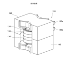
- Patent Document 1 As a conventional technique for downsizing a transformer with large current specifications, there is a technique that is disclosed in the following Patent Document 1 (particularly, FIG. 1), which is explained with reference to FIG.
- a transformer 120 is known that houses a primary coil 134, and a secondary coil 136 made of a cylindrical copper plate.
- the present invention was made in view of the above circumstances, and provides a low-profile transformer and its transformer that can promote reduction in the height and size of a product when a plurality of secondary coils are arranged outside the primary coil.
- the purpose is to provide a manufacturing method.
- the low profile transformer of the present invention is a magnetic core; a primary coil arranged in a wound state around the outer periphery of the magnetic core of the magnetic core; At least two cylindrical secondary coils are arranged on the outer periphery of the primary coil concentrically with the primary coil and concentrically with each other, Each of the at least two cylindrical secondary coils includes a cylindrical secondary coil main body part having a cylindrical shape that surrounds the slit on both sides, and a cylindrical secondary coil main body part having a cylindrical shape at one end in the longitudinal direction of the slit of the cylindrical secondary coil main body part.
- each of the at least two cylindrical secondary coils one of the terminal portions overlaps and is electrically connected to the other, and the other terminal portion is arranged so as to be in a non-contact state with each other.
- end portion of the cylindrical secondary coil main body refers to a region of the cylindrical secondary coil main body that faces across the slit.
- the terminal portion of the cylindrical secondary coil is formed by a conductive plate material constituting the cylindrical secondary coil body, and each terminal A notch is provided in a corner formed by a side surface in the extending direction of the terminal portion that is located on the opposite side of the terminal portion from the slit, and an edge surface of the cylindrical secondary coil main body portion.
- the one terminal portion and the other terminal portion are formed to be substantially parallel to each other and to extend outward while being bent. It is preferable.
- the cross section of the cylindrical secondary coil main body is rectangular, the long side surface of the rectangle forms a peripheral surface of the cylinder, and the rectangular main body has a rectangular cross section.
- the short side surface forms a radial surface of the cylinder.
- the primary coil is an air-core coil in which a conducting wire is wound a plurality of times.
- the method for manufacturing a low-profile transformer of the present invention includes: A first step of arranging a primary coil in a wound state around the outer periphery of the middle leg of one of the first core and the second core constituting the magnetic core; For each of the at least two cylindrical secondary coils, a cylindrical secondary coil main body part that is made of a predetermined metal material and goes around with a slit in between is formed, and a cylindrical secondary coil main body part that goes around the slit on one longitudinal end side of the slit is made of a predetermined metal material.
- a fifth step of combining the core and the second core to form the magnetic core, and storing the primary coil and the at least two cylindrical secondary coils in the magnetic core At least, the third step and the fourth step are arranged after the second step, and the fifth step is arranged after the first step, the second step, the third step, and the fourth step. It is characterized in that it is manufactured in the following order.
- the cylindrical secondary coil main body is formed by sheet metal processing the plate material made of the predetermined metal material, and the area near the end of the cylindrical secondary coil main body is including a manufacturing process in which the terminal portions are extended one by one in a predetermined direction from each, When extending the terminal portion in the predetermined direction, a side surface of each terminal portion in the extending direction is placed on the side opposite to the slit so that the extending direction of the terminal portion can be adjusted. It is preferable that a notch is provided in a corner formed by the side surface where the coil is located and the edge of the cylindrical secondary coil main body.
- the plurality of cylindrical secondary coils by configuring the plurality of cylindrical secondary coils to be arranged concentrically with each other on the same plane, the plurality of secondary coils can be arranged concentrically with each other on the same plane.
- the height dimension can be significantly lowered, making it possible to reduce the height and size of the product.
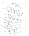
- FIG. 1 is an exploded perspective view showing the structure of a low-profile transformer according to an embodiment of the present invention.
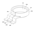
- FIG. 2 is an enlarged perspective view of a cylindrical secondary coil of a low-profile transformer according to an embodiment of the present invention.
- Two cylindrical secondary coils according to an embodiment of the present invention ((a) shows the overlapping state of the terminal portions of the two cylindrical secondary coils, (b) shows the shape of the first cylindrical secondary coil) , (c) is a schematic diagram showing the shape of a second cylindrical secondary coil.
- FIG. 1 is an exploded perspective view showing the structure of a low-profile transformer according to an embodiment of the present invention.
- FIG. 2 is an enlarged perspective view of a cylindrical secondary coil of a low-profile transformer according to an embodiment of the present invention.
- Two cylindrical secondary coils according to an embodiment of the present invention ((a) shows the overlapping state of the terminal portions of the two cylindrical secondary coils, (b) shows the shape of the first cylindrical secondary coil) , (c) is a schematic diagram showing
- FIG. 2 is a diagram for explaining a cylindrical secondary coil manufactured using a sheet metal processing method, in which (A) is a perspective view of the bottom viewed diagonally from below, and (B) is a plate-shaped conductive coil before sheet metal processing. It is a developed view showing the shape of the material.
- a schematic diagram for explaining the difference in height dimensions when Comparative Example (A) and Example (B) are assembled, respectively ((a) is a front view of the transformer, (b) is a diagram of the cylindrical secondary coil). (a perspective view showing the shape).
- FIG. 2 is a perspective view of a transformer according to the prior art, seen diagonally from above.
- the low profile transformer 10 of this embodiment has a first core 4 and a second core made of a PQ core, which constitute a magnetic core as main elements. 6, a primary coil (preferably an air-core coil) 34 formed by winding a conducting wire, and first and second cylindrical secondary coils 22, 24 made of cylindrical metal plates. ing.
- the first core 4 and the second core 6 are made of, for example, a ferrite core, and each has a cylindrical middle leg part 4c, 6c, an outer leg part 4a arranged on both sides of the middle leg part 4c, 6c, 4b, 6a, 6b, and back surface portions 4d, 6d connecting these middle leg portions 4c, 6c and outer leg portions 4a, 4b, 6a, 6b, respectively.
- Each core has a symmetrical shape, and both cores 4 and 6 are combined so that corresponding members are disposed opposite to each other.
- outer leg portions 4a, 4b, 6a, and 6b have a plate shape with an arcuate inner surface and a flat outer surface. Further, the corresponding tips of the three leg portions 4a, 4b, 4c constituting the first core 4 and the three leg portions 6a, 6b, 6c constituting the second core 6 preferably have minute gaps ( (not shown) so as to face each other.
- the structure of the transformer is preferably a closed magnetic circuit, and instead of the PQ core, an EE core, EI core, ER core, or the like may be used. Of course, it is also possible to adopt an open magnetic path structure using an I-core or the like. Further, a primary coil 34 of an air-core coil formed by winding a conducting wire is arranged around the outer periphery of the middle legs (magnetic cores) 4c, 6c of the first core 4 and second core 6 that constitute the PQ core. Ru.
- an insulating resin bobbin is arranged around the outer periphery of the middle legs (magnetic cores) 4c and 6c, and the conductor is wound around this resin bobbin. It may also be formed by Of course, even when using the primary coil 34 of the air-core coil described above, a resin bobbin may be arranged around the middle leg portions (magnetic cores) 4c, 6c.
- the inner diameter of the second cylindrical secondary coil 24 is larger than the outer diameter of the first cylindrical secondary coil 22.
- the size is set so that it fits into the secondary coil 24 with a slight spacing therebetween. That is, the primary coil 34, the first cylindrical secondary coil 22, and the Two cylindrical secondary coils 24 are arranged concentrically in this order.
- a bobbin made of an insulating material such as phenol resin or a bobbin formed to correspond to the shape of the cylindrical secondary coils 22, 24 is formed between the coils 34, 22, 24.
- a separator made of an insulating material or the like is interposed.
- the first cylindrical secondary coil 22 and the second cylindrical secondary coil 24 are made by processing a plate-shaped conductive material such as copper or aluminum into a cylindrical shape. Further, these cylindrical secondary coils 22 and 24 have cylindrical secondary coil main bodies 22d and 24d formed to substantially go around a plate-shaped conductive material with slits 22c and 24c in between, and At the lower ends in the longitudinal direction of both circumferential ends of the coils facing each other with the slits 22c and 24c in between, it extends from each of the end vicinity regions of the cylindrical secondary coil main bodies 22d and 24d that face each other with the slits 22c and 24c in between. Terminal portions 22a, 22b, 24a, and 24b are provided.
- terminal portions 34a and 34b of the primary coil 34 are arranged so as to be drawn out from the primary coil 34 upward in the drawing, as shown in FIGS. 1(A) and 1(B).
- the direction in which the 34b is pulled out is not limited to this.
- terminal portions 22a, 22b of the first cylindrical secondary coil 22 and the terminal portions 24a, 24b of the second cylindrical secondary coil 24 are configured so that they are all pulled out substantially parallel to each other. ing. Further, these terminal portions 22a, 22b, 24a, and 24b are formed so as to extend outward while being bent. That is, the terminal portions 22a, 22b, 24a, and 24b extend forward from the cylindrical secondary coil body portions 22d and 24d, then bend downward, and then further bend forward.
- the bottom surfaces of the forwardly extending tips of the terminals 22a, 22b, 24a, and 24b are configured to be electrically connected to a conductive pattern on the substrate, for example, by soldering.
- One terminal portion 24a of the second cylindrical secondary coil 24 is superimposed on one terminal portion 22a of the first cylindrical secondary coil 22, and these two terminal portions 22a, 24a are electrically connected. (see FIGS. 4(a), (b), and (c)).
- the other terminal portion 24b of the second cylindrical secondary coil 24 is arranged so as not to overlap the other terminal portion 22b of the first cylindrical secondary coil 22, and the two terminal portions 22b , 24b are configured to be spaced apart from each other (see FIGS. 4(a), (b), and (c)).
- the tips of both terminal portions 22a, b of the first cylindrical secondary coil 22 are created so as to be installed on the same plane (board surface), whereas the tips of the second cylindrical secondary coil 22 are
- the terminal portions 24a, b of the secondary coil 24 are configured such that the tip of the terminal portion 24a is located above the tip of the terminal portion 24b by the thickness of the terminal portion 22a. This is because the tip of the terminal portion 24a is superimposed on the tip of the terminal portion 22a of the first cylindrical secondary coil 22, whereas the tip of the terminal portion 24b is superimposed on the tip of the terminal portion 22a of the first cylindrical secondary coil 22. This is because, like the terminal portions 22a and 22b of the secondary coil 22, it is necessary to configure it so that it is installed on the substrate surface.
- the terminal portions 22a, 24a that are overlapped with each other may be placed between the other terminal portions 22b, 24b.
- the overlapping terminal parts 22a, 24a will overlap the other terminal parts 22b, 24b. There is no need to place it in between.
- the position of one of the stacked terminals and the width of the slit are changed appropriately, and the terminals of the other are placed at a predetermined distance from each other. It is necessary to adjust it so that it can be placed in the position shown below.
- terminal portions 22a, 22b, 24a, and 24b do not necessarily have to be configured to extend outward while being bent as in the above embodiment, but may extend linearly. It may be configured to do so. Further, for example, when connecting to a conductive pattern on the back side by passing through a through hole of the board, it is necessary to make the downwardly extending portions of the terminal portions 22a, 22b, 24a, and 24b longer. It is important to configure the
- the cross section of the cylindrical secondary coil body parts 22d and 24d is rectangular, and the long side surface of this rectangle forms the circumferential surface of the cylinder.
- the short side surface of the cylinder forms the radial surface of the cylinder.
- the cylindrical secondary coils 22 and 24 of the low-profile transformer 10 can be manufactured by various methods such as metal molding and sheet metal processing, but it is convenient to use sheet metal processing. Therefore, it is preferable.
- this sheet metal processing method for example, as shown in FIG. Cutouts 24e and f are provided at the edge portions (corners) of the shaped secondary coil main body portion 24d.
- a first step is performed in which a primary coil 34 of an air-core coil made by winding a conducting wire is placed around the outer periphery of the middle leg (magnetic core) 4c of the first core 4 made of a PQ core that constitutes a magnetic core.
- an insulating resin bobbin is placed around the outer periphery of the middle leg (magnetic core) 4c, and the primary coil 34 is wound by winding the conductive wire around the resin bobbin. may be formed.
- a third step is performed in which the two cylindrical secondary coils 22 and 32 formed as described above are arranged around the outer periphery of the primary coil 34, concentrically with the primary coil 34. That is, from the inside to the outside, the primary coil 34, the first cylindrical secondary coil 22, and the second cylindrical secondary coil 24 are arranged around the middle leg portions (magnetic cores) 4c, 6c. are arranged in concentric circles.
- one terminal portion 22a, 24a is overlapped with each other and electrically connected.
- a fourth step is performed in which the other terminal portions 22b and 24b are arranged so as not to be in contact with each other.
- the middle leg portion 6c and outer leg portions 6a, 6b of the second core 6 made of a PQ core constituting the magnetic core are connected to the middle leg portion 6c and outer leg portions 6a, 6b of the first core 4.
- a fifth step is performed in which the first core 4 and the second core 6 are combined so that they face each other with a gap in between.
- the primary coil 34 and the two cylindrical secondary coils 22 and 24 can be housed concentrically between the first core 4 and the second core 6.
- the third step and the fourth step are performed after the second step, but the first step is performed between the second step and the third step, or after the third step. is also possible.
- the transformer according to the comparative example has a primary coil 234 sandwiched from above and below, and two secondary coils 222 shown in FIGS. 6(A)(b). , 224 are arranged so as to overlap in the axial direction.
- the secondary coils 222 and 224 of this comparative example are formed by winding rectangular copper wires, and have an annular portion and two bent terminal portions extending from the annular portion. However, the cross section of the annular portion is short in the axial direction.
- the low-profile transformer according to the example has two Two cylindrical secondary coils 22 and 24 are arranged concentrically.
- the cylindrical secondary coils 22 and 24 of this comparative example are formed by winding rectangular copper wires, and have a cylindrical portion and two bent terminal portions extending from the cylindrical portion. This is the same as in the above comparative example, but the cross section of the cylindrical portion is short in the radial direction.
- the long side of this rectangular wire is, for example, 10 mm and the short side is 2.0 mm (the cross-sectional area is 20.0 mm 2 ), and in the cylindrical part, the long side is axial and the short side is radial.
- the low-profile transformer and the method for manufacturing the low-profile transformer of the present invention are not limited to those of the above embodiments, and various other embodiments may be applied.
- two cylindrical secondary coils are arranged concentrically, but three or more cylindrical secondary coils may be arranged concentrically.
- the terminal portion of the cylindrical secondary coil is formed so as to extend outward while being bent. ) may be extended.
- the core is not limited to the type that combines two PQ cores to form a closed magnetic circuit, but may also include a combination of other cores such as two E cores or ER cores.
- a closed magnetic circuit may be constructed by.
- the two terminal portions of the cylindrical secondary coil are approximately parallel to each other, which allows the terminal portions to be arranged compactly. If there is enough room, they do not necessarily have to be parallel to each other.
- a notch is formed in the corner formed by the side surface located on the opposite side from the slit among the side surfaces in the extending direction of the terminal portion and the circumferential surface of the cylindrical secondary coil main body.
- the cylindrical secondary coil is formed by a method such as molding rather than sheet metal processing, or if the terminal part is connected to the cylindrical secondary coil body by welding etc., the above notch is required. does not need to be provided.
- the first to fifth steps described above are manufactured in this order, but at least the third step and the second step are more important than the second step. If manufacturing is performed in an order such that the fourth step comes later, and the fifth step comes later than the first, second, third, and fourth steps, other steps can be performed. can be produced in any order depending on the situation. For example, the second step may be performed before the first step, or the second and fourth steps may be performed in this order, and then the first and third steps may be performed in this order. .
- Second core 10 Low profile transformer 22 First cylindrical secondary coil 22a, 22b, 24a, 24b, 34a, 34b, 136a Terminal portion 22c, 24c Slit 22d, 24d Cylindrical secondary coil body portion 24 Second cylindrical secondary coil 24e, 24f Notch 120 Transformer 146, 148 PQ core 34, 134, 234 Primary coil 222, 136, 224 Secondary coil
Landscapes
- Engineering & Computer Science (AREA)
- Power Engineering (AREA)
- Coils Of Transformers For General Uses (AREA)
Abstract
Description
また、車載コンバータユニットの小型軽量化が求められており、特に、大型部品であるメイントランスの小型軽量化の促進が急務である。
大電流仕様のトランスにおける小型化を図るための従来技術としては、本願図7により説明される、下記特許文献1(特に図1)に開示されてなる、2つのPQコア146、148の間に、1次コイル134、および円筒状の銅板からなる2次コイル136を収納したトランス120が知られている。
しかしながら、この引用文献1のものにおいては、積み重ねた2次コイル136、136の個数に応じて製品高さが増大し、製品の低背化、小型化を促進することが困難であった。
磁性体コアと、
該磁性体コアの磁心部の外周に巻回状態で配置された1次コイルと、
前記1次コイルの外周に、該1次コイルと同心円状に、かつ互いに同心円状に配置された、少なくとも2つの円筒状2次コイルと、を備え、
前記少なくとも2つの円筒状2次コイルの各々には、スリットを挟んで周回した円筒形状をなす円筒状2次コイル本体部と、この円筒状2次コイル本体部の前記スリットの長手方向一端側において、このスリットを挟んで対向する該円筒状2次コイル本体部の端部近傍領域の各々から外部に向けて延在する端子部とが設けられており、
前記少なくとも2つの円筒状2次コイルの各々における一方の前記端子部が互いに重なり合って電気的に接続されるとともに、他方の前記端子部が互いに非接触状態となるように配置されてなる、ことを特徴とするものである。
ここで、上記「円筒状2次コイル本体部の端部」とは、円筒状2次コイル本体部のスリットを挟んで対向する領域、を称するものとする。
また、前記少なくとも2つの円筒状2次コイルの各々において、前記一方の端子部と前記他方の端子部が互いにほぼ平行とされ、かつ屈曲しつつ外部に向けて延在するように形成されていることが好ましい。
また、前記1次コイルが導線を複数回に亘り巻回した空芯コイルとされていることが好ましい。
磁性体コアを構成する第1コアと第2コアのうちの一方の中脚部の外周に、1次コイルを巻回状態で配置する第1工程と、
少なくとも2つの円筒状2次コイルの各々について、所定の金属材料にて、スリットを挟んで周回する円筒状2次コイル本体部を形成するとともに、該スリットの長手方向一端側の、該スリットを挟んで対向する該円筒状2次コイル本体部の端部近傍領域の各々から所定方向に端子部を1つずつ延在させる第2工程と、
前記1次コイルの外周に、該1次コイルと同心円状にかつ互いに同心円状に、前記少なくとも2つの円筒状2次コイルを、各々配置する第3工程と、
前記少なくとも2つの円筒状2次コイルの各々における、2つずつの前記端子部のうち、一方の前記端子部を互いに重ね合わせて電気的に接続するとともに、他方の前記端子部を互いに非接触状態となるように配置する第4工程と、
前記同心円状に配置された、前記1次コイル、および前記少なくとも2つの円筒状2次コイルの中心に位置する、前記一方の中脚部に対し、他方の中脚部を突き合せて前記第1コアと前記第2コアを組み合わせて前記磁性体コアを形成し、この磁性体コア内に、前記1次コイル、および前記少なくとも2つの円筒状2次コイルを収納する第5工程とを、
少なくとも、前記第2工程よりも前記第3工程および第4工程が後となるように、かつ前記第1工程、第2工程、前記第3工程および前記第4工程よりも前記第5工程が後となるような順序で製造を行うことを特徴とするものである。
該所定方向に該端子部を延在させる際には、該端子部の延在方向が調整可能となるように、各々の該端子部の延在方向の側面のうち前記スリットとは逆側に位置する側面と、前記円筒状2次コイル本体部の縁部とにより形成される隅部に切り欠きを設けたことが好ましい。
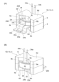
図1(A)は、本発明の実施形態に係る低背トランスを、正面側斜め上方から見た斜視図、図1(B)は、本発明の実施形態に係る低背トランスを、背面側斜め上方から見た斜視図である。また、図2は、本発明の実施形態に係る低背トランスを分解して示す斜視図である。
この実施形態の低背トランス10は、図1(A)、(B)および図2に示すように、主要素として、磁性体コアを構成する、PQコアからなる第1コア4および第2コア6と、導線を巻回してなる1次コイル(空芯コイルとすることが好ましい)34と、金属板を円筒状とした、第1および第2の円筒状2次コイル22、24とを備えている。
第1コア4および第2コア6は、例えばフェライトコア製であって、各々円柱状の中脚部4c、6cと、その中脚部4c、6cの両側部に配された外脚部4a、4b、6a、6bと、これら中脚部4c、6cおよび外脚部4a、4b、6a、6bを接続する背面部4d、6dとを各々有し、これら第1コア4および第2コア6の各々は対称形状とされ、また、これら両コア4、6は、対応する部材が互いに対向配置されるように組み合わせられる。
また、第1コア4を構成する3つの脚部4a、4b、4cと、第2コア6を構成する3つの脚部6a、6b、6cの対応する各先端は、好ましくは微小間隔のギャップ(不図示)を介して対向するように配される。
また、上述した、PQコアを構成する第1コア4および第2コア6の中脚部(磁心)4c、6cの外周に、導線を巻回してなる空芯コイルの1次コイル34が配置される。
また、1次コイル34を空芯コイルとして形成するのではなく、中脚部(磁心)4c、6cの外周に絶縁性を有する樹脂製ボビンを配し、この樹脂製ボビンに導線を巻回することにより形成してもよい。
勿論、上述した空芯コイルの1次コイル34を用いる場合にも、上記中脚部(磁心)4c、6cの周りに樹脂製ボビンを配置してもよい。
すなわち、PQコアを構成する第1コア4および第2コア6の中脚部(磁心)4c、6cの中心軸を中心として、1次コイル34、第1の円筒状2次コイル22、および第2の円筒状2次コイル24が、この順に同心円状に配置される。なお、図示はされていないが、実際には、各コイル34、22、24間に、フェノール樹脂等の絶縁材からなるボビンや、円筒状2次コイル22、24の形状に対応させて成形された絶縁材からなるセパレータ等を介在させる。
なお、1次コイル34の端子部34a、34bは、図1(A)、(B)に示すように、1次コイル34から図面上方に引き出されるように配されているが、端子部34a、34bを引き出す方向は、これに限られるものではない。
すなわち、端子部22a、22b、24a、24bは、円筒状2次コイル本体部22d、24dから前方に向けて延在した後、下方に向けて屈曲し、さらに前方に向けて屈曲する。端子部22a、22b、24a、24bの前方に向けて延在する先端部はその底面が、例えば基板上の導電パターンに半田付けにより電気的に接続するように構成される。
これに対し、第2の円筒状2次コイル24の他方の端子部24bは、第1の円筒状2次コイル22の他方の端子部22bとは重ならないように配置され、2つの端子部22b、24bが互いに離間するように構成されている(図4(a)、(b)、(c)を参照)。
このため、第1の円筒状2次コイル22の両方の端子部22a、bの先端部は、同一平面(基板面)上に設置するように作成されているのに対し、第2の円筒状2次コイル24の端子部24a、bにおいては、端子部22aの厚み分だけ、端子部24aの先端部が端子部24bの先端部よりも上方に位置するように構成されている。これは、端子部24aの先端部が、第1の円筒状2次コイル22の端子部22aの先端部上に重ね合わせられるのに対し、端子部24bの先端部は、第1の円筒状2次コイル22の端子部22a、bと同様に基板面に設置されるように構成する必要があるためである。
特に、円筒状2次コイルを同心円状に3つ以上重ねる態様とした場合には、重ね合わせられる一方の端子部の位置や、スリットの幅を適宜変えて、他方の端子部を互いに離間した所定の位置に配置し得るように調整する必要がある。
なお、2つの円筒状2次コイル22、24は、コイル径が互いに異なることから、コイル全長が互いに異なることになり、通常であれば、出力される電流値が異なることになる。両者間で出力される電流値を同等(あるいはその他の所定の比率)とする必要がある場合には、コイル径に応じて各コイル22、24の断面積を調整することが肝要である。
この板金加工の手法による場合には、例えば、この円筒状2次コイル24を底部斜め下方から見た図である図5(A)に示すように、端子部24a、24bが分岐される、円筒状2次コイル本体部24dの縁部部分(隅部)に切り欠き24e、fが設けられている。この切り欠き24e、fを設けることにより、円筒状2次コイル本体部24dを円筒状に形成する際に、2つの端子部24a、24bが互いに「ハの字」状の末拡がり形状とならずに、互いに平行となる形状にて前方に延在させることができる。
以下、本実施形態に係る低背トランスの製造方法について、一例を用いて簡単に説明する。
まず、磁性体コアを構成するPQコアからなる第1コア4の中脚部(磁心)4cの外周に、導線を巻回してなる空芯コイルの1次コイル34を配置する第1工程を行う。なお、第1工程は、前述したように、中脚部(磁心)4cの外周に絶縁性を有する樹脂製ボビンを配し、この樹脂製ボビンに導線を巻回することにより1次コイル34を形成してもよい。
なお、この第2工程は、第1工程の前に行うことも可能である。
なお、上記第3工程および上記第4工程は上記第2工程の後に行うことになるが、第1工程は、上記第2工程と上記第3工程の間、または上記第3工程の後に行うことも可能である。
以下、実施例を比較例と比較することにより、本実施形態に係る低背トランスにより低背化を促進することができることを具体的に示す(図6を参照)。
比較例に係るトランスは図6(A)(a)に示すように、1次コイル234を上下から挟んで、(A)(b)に示す2つの2次コイル222、224を、軸方向に重畳させるように配設したものである。
この比較例の2次コイル222、224は、銅製の平角線を周回させて形成したものであり、円環状部分と、この円環状部分から2つの屈曲した端子部を延出させたものであるが、円環状部分の断面は軸方向に短い形状とされている。具体的には、この平角線は、例えば、長辺が6mm、短辺が3.3mm(断面積は19.8mm2)とされ、円環状部分では、長辺が径方向に、短辺が軸方向とされるように配されている。
このように配された比較例のトランスは、正面図である(A)(a)に示されるように、横幅は50mm、高さは36mmに形成される。
一方、実施例に係る低背トランスは図6(B)(a)に示すように、1次コイル(不図示)の外周に、(B)(b)に示す2つの円筒状2次コイル22、24を、同心円状に配設したものである。
この比較例の円筒状2次コイル22、24は、銅製の平角線を周回させて形成したものであり、円筒状部分と、この円筒状部分から2つの屈曲した端子部を延出させたものであることは上記比較例と同様であるが、円筒状部分の断面は径方向に短い形状とされている。具体的には、この平角線は、例えば、長辺が10mm、短辺が2.0mm(断面積は20.0mm2)とされ、円筒状部分では、長辺が軸方向に、短辺が径方向とされるように配されている。
このように配された実施例の低背トランスは、正面図である(B)(a)に示されるように、横幅は50mmで上記比較例と同じであるが、高さは28.4mmに形成される。
このように、本実施例の低背トランスによれば、従来の比較例のトランスと比較して、低減量は7.6mm、低減率は21%と大幅に低背化されている。
なお、本発明の低背トランスおよび低背トランスの製造方法としては、上記実施形態のものに限られるものではなく、その他の種々の態様のものを適用することができる。
例えば、上記実施形態においては、2つの円筒状2次コイルを同心円状に配置しているが、3つ以上の円筒状2次コイルを同心円状に配置してもよい。
また、コアについても、前述したように、2つのPQコアを組み合わせて閉磁路を構成するタイプのものに限られるものではなく、2つのEコア、ERコア等の他のコアを組み合わせたもの等によって閉磁路を構成したものであってもよい。また、Iコア等によって開磁路を構成したものも使用することができる。
また、上記実施形態においては、端子部の延在方向の側面のうちスリットとは逆側に位置する側面と、円筒状2次コイル本体部の周面とにより形成される隅部に切り欠きを設けているが、円筒状2次コイルを、板金加工ではなく金型成型等の手法によって形成する場合、あるいは円筒状2次コイル本体部に端子部を溶接等により接続する場合には上記切り欠きは設けずともよい。
例えば、第2工程は第1工程の前に行ってもよいし、第2工程と第4工程をこの順序で行ってから、第1工程と第3工程をこの順序で行うようにしてもよい。
4a、4b、6a、6b 外脚部
4c、6c 中脚部
4d、6d 背面部
6 第2コア
10 低背トランス
22 第1の円筒状2次コイル
22a、22b、24a、24b、34a、34b、136a 端子部
22c、24c スリット
22d、24d 円筒状2次コイル本体部
24 第2の円筒状2次コイル
24e、24f 切り欠き
120 トランス
146、148 PQコア
34、134、234 1次コイル
222、136、224 2次コイル
Claims (7)
- 磁性体コアと、
該磁性体コアの磁心部の外周に巻回状態で配置された1次コイルと、
前記1次コイルの外周に、該1次コイルと同心円状に、かつ互いに同心円状に配置された、少なくとも2つの円筒状2次コイルと、を備え、
前記少なくとも2つの円筒状2次コイルの各々には、スリットを挟んで周回した円筒形状をなす円筒状2次コイル本体部と、この円筒状2次コイル本体部の前記スリットの長手方向一端側において、このスリットを挟んで対向する該円筒状2次コイル本体部の端部近傍領域の各々から外部に向けて延在する端子部とが設けられており、
前記少なくとも2つの円筒状2次コイルの各々における一方の前記端子部が互いに重なり合って電気的に接続されるとともに、他方の前記端子部が互いに非接触状態となるように配置されてなる、ことを特徴とする低背トランス。 - 前記少なくとも2つの円筒状2次コイルの各々において、前記円筒状2次コイル本体部を構成する導電性板材によって該円筒状2次コイルの前記端子部が形成されており、各々の該端子部の延在方向の側面のうち前記スリットとは該端子部の逆側に位置する側面と、前記円筒状2次コイル本体部の縁面とにより形成される隅部に切り欠きが設けられていることを特徴とする請求項1に記載の低背トランス。
- 前記少なくとも2つの円筒状2次コイルの各々において、前記一方の端子部と前記他方の端子部が互いにほぼ平行とされ、かつ屈曲しつつ外部に向けて延在するように形成されていることを特徴とする請求項1または2に記載の低背トランス。
- 前記少なくとも2つの円筒状2次コイルの各々において、前記円筒状2次コイル本体部の断面が矩形とされ、該矩形の長辺側の面が円筒の周面を形成し、該矩形の短辺側の面が該円筒の径方向の面を形成することを特徴とする請求項1~3のうちいずれか1項に記載の低背トランス。
- 前記1次コイルが導線を複数回に亘り巻回した空芯コイルとされていることを特徴とする請求項1~4のうちいずれか1項に記載の低背トランス。
- 磁性体コアを構成する第1コアと第2コアのうちの一方の中脚部の外周に、1次コイルを巻回状態で配置する第1工程と、
少なくとも2つの円筒状2次コイルの各々について、所定の金属材料にて、スリットを挟んで周回する円筒状2次コイル本体部を形成するとともに、該スリットの長手方向一端側の、該スリットを挟んで対向する円筒状2次コイル本体部の端部近傍領域の各々から所定方向に端子部を1つずつ延在させる第2工程と、
前記1次コイルの外周に、該1次コイルと同心円状にかつ互いに同心円状に、前記少なくとも2つの円筒状2次コイルを、各々配置する第3工程と、
前記少なくとも2つの円筒状2次コイルの各々における、2つずつの前記端子部のうち、一方の前記端子部を互いに重ね合わせて電気的に接続するとともに、他方の前記端子部を互いに非接触状態となるように配置する第4工程と、
前記同心円状に配置された、前記1次コイル、および前記少なくとも2つの円筒状2次コイルの中心に位置する、前記一方の中脚部に対し、他方の中脚部を突き合せて前記第1コアと前記第2コアを組み合わせて前記磁性体コアを形成し、この磁性体コア内に、前記1次コイル、および前記少なくとも2つの円筒状2次コイルを収納する第5工程とを、
少なくとも、前記第2工程よりも前記第3工程および第4工程が後となるように、かつ前記第1工程、第2工程、前記第3工程および前記第4工程よりも前記第5工程が後となるような順序で製造を行うことを特徴とする低背トランスの製造方法。 - 前記第2工程が、前記所定の金属材料からなる板材を板金加工することにより、前記円筒状2次コイル本体部を形成するとともに、前記円筒状2次コイル本体部の端部近傍領域の各々から所定方向に端子部を1つずつ延在させる製造工程を含み、
該所定方向に該端子部を延在させる際には、該端子部の延在方向が調整可能となるように、各々の該端子部の延在方向の側面のうち前記スリットとは逆側に位置する側面と、前記円筒状2次コイル本体部の縁部とにより形成される隅部に切り欠きを設けたことを特徴とする請求項6記載の低背トランスの製造方法。
Priority Applications (3)
| Application Number | Priority Date | Filing Date | Title |
|---|---|---|---|
| CN202280094312.6A CN118974857A (zh) | 2022-05-09 | 2022-05-09 | 低高度变压器及其制造方法 |
| JP2024520105A JP7845461B2 (ja) | 2022-05-09 | 2022-05-09 | 低背トランスおよびその製造方法 |
| PCT/JP2022/019736 WO2023218510A1 (ja) | 2022-05-09 | 2022-05-09 | 低背トランスおよびその製造方法 |
Applications Claiming Priority (1)
| Application Number | Priority Date | Filing Date | Title |
|---|---|---|---|
| PCT/JP2022/019736 WO2023218510A1 (ja) | 2022-05-09 | 2022-05-09 | 低背トランスおよびその製造方法 |
Publications (1)
| Publication Number | Publication Date |
|---|---|
| WO2023218510A1 true WO2023218510A1 (ja) | 2023-11-16 |
Family
ID=88729979
Family Applications (1)
| Application Number | Title | Priority Date | Filing Date |
|---|---|---|---|
| PCT/JP2022/019736 Ceased WO2023218510A1 (ja) | 2022-05-09 | 2022-05-09 | 低背トランスおよびその製造方法 |
Country Status (3)
| Country | Link |
|---|---|
| JP (1) | JP7845461B2 (ja) |
| CN (1) | CN118974857A (ja) |
| WO (1) | WO2023218510A1 (ja) |
Citations (6)
| Publication number | Priority date | Publication date | Assignee | Title |
|---|---|---|---|---|
| JP2001155933A (ja) * | 1999-11-30 | 2001-06-08 | Fujitsu Denso Ltd | 金属板巻線の構造 |
| JP2003151834A (ja) * | 2001-11-15 | 2003-05-23 | Cosel Co Ltd | トランスの巻線構造 |
| JP2005021955A (ja) * | 2003-07-04 | 2005-01-27 | Oota:Kk | 金属板の曲げ成形方法および装置 |
| US20110254651A1 (en) * | 2010-04-19 | 2011-10-20 | Samsung Electro-Mechanics Co., Ltd. | Transformer and electronic apparatus including the same |
| JP2015185725A (ja) * | 2014-03-25 | 2015-10-22 | Fdk株式会社 | トランス |
| JP2017042804A (ja) * | 2015-08-28 | 2017-03-02 | 株式会社アマダホールディングス | 折曲げ加工方法 |
Family Cites Families (1)
| Publication number | Priority date | Publication date | Assignee | Title |
|---|---|---|---|---|
| JP3647913B2 (ja) * | 1994-10-03 | 2005-05-18 | 株式会社タムラ製作所 | 高周波スイッチングトランス |
-
2022
- 2022-05-09 WO PCT/JP2022/019736 patent/WO2023218510A1/ja not_active Ceased
- 2022-05-09 JP JP2024520105A patent/JP7845461B2/ja active Active
- 2022-05-09 CN CN202280094312.6A patent/CN118974857A/zh active Pending
Patent Citations (6)
| Publication number | Priority date | Publication date | Assignee | Title |
|---|---|---|---|---|
| JP2001155933A (ja) * | 1999-11-30 | 2001-06-08 | Fujitsu Denso Ltd | 金属板巻線の構造 |
| JP2003151834A (ja) * | 2001-11-15 | 2003-05-23 | Cosel Co Ltd | トランスの巻線構造 |
| JP2005021955A (ja) * | 2003-07-04 | 2005-01-27 | Oota:Kk | 金属板の曲げ成形方法および装置 |
| US20110254651A1 (en) * | 2010-04-19 | 2011-10-20 | Samsung Electro-Mechanics Co., Ltd. | Transformer and electronic apparatus including the same |
| JP2015185725A (ja) * | 2014-03-25 | 2015-10-22 | Fdk株式会社 | トランス |
| JP2017042804A (ja) * | 2015-08-28 | 2017-03-02 | 株式会社アマダホールディングス | 折曲げ加工方法 |
Also Published As
| Publication number | Publication date |
|---|---|
| JPWO2023218510A1 (ja) | 2023-11-16 |
| JP7845461B2 (ja) | 2026-04-14 |
| CN118974857A (zh) | 2024-11-15 |
Similar Documents
| Publication | Publication Date | Title |
|---|---|---|
| JP3755729B2 (ja) | 電源トランス | |
| JP2002175922A (ja) | 高周波大電流変圧器 | |
| WO2004032158A1 (en) | Coil form | |
| JP2000223320A (ja) | 大電流用トランス | |
| JP3777962B2 (ja) | 電磁装置及び高電圧発生装置 | |
| JP5110735B2 (ja) | トランス | |
| JP2001035730A (ja) | 高周波トランス | |
| JP4845199B2 (ja) | トランス | |
| JP2000173840A (ja) | コイルユニット及びトランス | |
| JP4595312B2 (ja) | トランス | |
| US8508323B2 (en) | Transformer | |
| JP2003264110A (ja) | スパイラルコイルとトランス | |
| WO2023218510A1 (ja) | 低背トランスおよびその製造方法 | |
| JPH08153630A (ja) | トランス | |
| JP2009302492A (ja) | 電磁誘導器 | |
| JP3391596B2 (ja) | 線輪及び変成器 | |
| JP2005086052A (ja) | トランスおよびこのトランスを備えた電源装置 | |
| JP2010251364A (ja) | コイル用ボビン、巻線部品、コイル部品、スイッチング電源装置、及びコイル部品の製造方法 | |
| JP2008205212A (ja) | トランス | |
| JP2001284130A (ja) | インダクタンス素子 | |
| JP2006100453A (ja) | トランス | |
| JP5218773B2 (ja) | リアクトル及びコンバータ | |
| JP2000036416A (ja) | コイル部品 | |
| JPH09199347A (ja) | シートトランス | |
| CN220543732U (zh) | 变压器 |
Legal Events
| Date | Code | Title | Description |
|---|---|---|---|
| 121 | Ep: the epo has been informed by wipo that ep was designated in this application |
Ref document number: 22941592 Country of ref document: EP Kind code of ref document: A1 |
|
| ENP | Entry into the national phase |
Ref document number: 2024520105 Country of ref document: JP Kind code of ref document: A |
|
| WWE | Wipo information: entry into national phase |
Ref document number: 202280094312.6 Country of ref document: CN |
|
| NENP | Non-entry into the national phase |
Ref country code: DE |
|
| 122 | Ep: pct application non-entry in european phase |
Ref document number: 22941592 Country of ref document: EP Kind code of ref document: A1 |