WO2023214539A1 - ガラス板の洗浄装置及びガラス板の製造方法 - Google Patents
ガラス板の洗浄装置及びガラス板の製造方法 Download PDFInfo
- Publication number
- WO2023214539A1 WO2023214539A1 PCT/JP2023/016718 JP2023016718W WO2023214539A1 WO 2023214539 A1 WO2023214539 A1 WO 2023214539A1 JP 2023016718 W JP2023016718 W JP 2023016718W WO 2023214539 A1 WO2023214539 A1 WO 2023214539A1
- Authority
- WO
- WIPO (PCT)
- Prior art keywords
- cleaning
- rotating shaft
- glass plate
- cleaning liquid
- liquid supply
- Prior art date
- Legal status (The legal status is an assumption and is not a legal conclusion. Google has not performed a legal analysis and makes no representation as to the accuracy of the status listed.)
- Ceased
Links
Images






Classifications
-
- B—PERFORMING OPERATIONS; TRANSPORTING
- B08—CLEANING
- B08B—CLEANING IN GENERAL; PREVENTION OF FOULING IN GENERAL
- B08B1/00—Cleaning by methods involving the use of tools
- B08B1/10—Cleaning by methods involving the use of tools characterised by the type of cleaning tool
- B08B1/12—Brushes
-
- B—PERFORMING OPERATIONS; TRANSPORTING
- B08—CLEANING
- B08B—CLEANING IN GENERAL; PREVENTION OF FOULING IN GENERAL
- B08B1/00—Cleaning by methods involving the use of tools
- B08B1/10—Cleaning by methods involving the use of tools characterised by the type of cleaning tool
- B08B1/14—Wipes; Absorbent members, e.g. swabs or sponges
-
- B—PERFORMING OPERATIONS; TRANSPORTING
- B08—CLEANING
- B08B—CLEANING IN GENERAL; PREVENTION OF FOULING IN GENERAL
- B08B1/00—Cleaning by methods involving the use of tools
- B08B1/20—Cleaning of moving articles, e.g. of moving webs or of objects on a conveyor
-
- B—PERFORMING OPERATIONS; TRANSPORTING
- B08—CLEANING
- B08B—CLEANING IN GENERAL; PREVENTION OF FOULING IN GENERAL
- B08B1/00—Cleaning by methods involving the use of tools
- B08B1/30—Cleaning by methods involving the use of tools by movement of cleaning members over a surface
- B08B1/32—Cleaning by methods involving the use of tools by movement of cleaning members over a surface using rotary cleaning members
- B08B1/34—Cleaning by methods involving the use of tools by movement of cleaning members over a surface using rotary cleaning members rotating about an axis parallel to the surface
-
- B—PERFORMING OPERATIONS; TRANSPORTING
- B08—CLEANING
- B08B—CLEANING IN GENERAL; PREVENTION OF FOULING IN GENERAL
- B08B1/00—Cleaning by methods involving the use of tools
- B08B1/30—Cleaning by methods involving the use of tools by movement of cleaning members over a surface
- B08B1/32—Cleaning by methods involving the use of tools by movement of cleaning members over a surface using rotary cleaning members
- B08B1/36—Cleaning by methods involving the use of tools by movement of cleaning members over a surface using rotary cleaning members rotating about an axis orthogonal to the surface
-
- B—PERFORMING OPERATIONS; TRANSPORTING
- B08—CLEANING
- B08B—CLEANING IN GENERAL; PREVENTION OF FOULING IN GENERAL
- B08B1/00—Cleaning by methods involving the use of tools
- B08B1/40—Cleaning tools with integrated means for dispensing fluids, e.g. water, steam or detergents
-
- B—PERFORMING OPERATIONS; TRANSPORTING
- B08—CLEANING
- B08B—CLEANING IN GENERAL; PREVENTION OF FOULING IN GENERAL
- B08B3/00—Cleaning by methods involving the use or presence of liquid or steam
- B08B3/02—Cleaning by the force of jets or sprays
-
- C—CHEMISTRY; METALLURGY
- C03—GLASS; MINERAL OR SLAG WOOL
- C03C—CHEMICAL COMPOSITION OF GLASSES, GLAZES OR VITREOUS ENAMELS; SURFACE TREATMENT OF GLASS; SURFACE TREATMENT OF FIBRES OR FILAMENTS MADE FROM GLASS, MINERALS OR SLAGS; JOINING GLASS TO GLASS OR OTHER MATERIALS
- C03C23/00—Other surface treatment of glass not in the form of fibres or filaments
Definitions
- the present invention relates to a glass plate cleaning apparatus and a glass plate manufacturing method including a cleaning process.
- Displays such as liquid crystal displays and organic EL displays are becoming increasingly high-definition. Accordingly, a dense electric circuit is formed on a glass plate used as a display substrate during the display manufacturing process. Therefore, this type of glass plate is required to have high cleanliness, free from dust and dirt.
- a cleaning process is generally provided in which the glass plate is cleaned using a cleaning device. It is true.
- Examples of the method for cleaning the main surface of the glass plate include the method disclosed in Patent Document 1.
- each cleaning member is rotated in a state in which a plurality of cleaning members are in contact with a glass plate. In this way, the glass plate is cleaned while being rubbed.
- the cleaning member is attached to the tip of the rotating shaft (spindle) and rotates together with the rotating shaft.
- the cleaning device disclosed in Patent Document 1 includes a housing having an internal space in which cleaning liquid is stored, and the vertically intermediate portion of the rotating shaft is immersed in the cleaning liquid within the housing.
- a cleaning liquid supply path (communication path) is provided that communicates the outer peripheral surface of the intermediate portion of the rotating shaft immersed in the cleaning liquid with the lower end of the rotating shaft, and through this cleaning liquid supply path, The cleaning liquid inside the housing is supplied to the cleaning member.
- the glass plate may be tilted in the width direction, as disclosed in FIG. 3 of Patent Document 1.
- the cleaning device is also arranged at an angle depending on the inclination of the glass plate. Therefore, the casing in which the cleaning liquid is stored also assumes an inclined posture matching the inclination of the glass plate.
- the depth of the cleaning liquid inside the housing changes in the width direction. In other words, if one end in the width direction is located higher than the other end in the width direction, the depth of the cleaning liquid inside the casing at one end in the width direction is shallower than the depth of the cleaning liquid inside the casing at the other end in the width direction. .
- the cleaning liquid cannot be sufficiently supplied to the cleaning member through the cleaning liquid supply path in a portion where the depth of the cleaning liquid inside the housing is shallow.
- Patent Document 1 there is still a risk that cleaning liquid may not be sufficiently supplied to the cleaning member, resulting in uneven cleaning of the glass plate.
- An object of the present invention is to reliably reduce uneven cleaning of glass plates.
- the glass plate cleaning device which was invented to solve the above problems, includes an upper rotating shaft and an upper cleaning member that is provided at the lower end of the upper rotating shaft and cleans the upper surface of the glass plate.
- the cleaning liquid supplied from the cleaning liquid supply section flows into the upper cleaning liquid supply path from the inlet of the upper cleaning liquid supply path provided in the upper rotating shaft.
- the cleaning liquid that has flowed in from the inlet flows through the upper cleaning liquid supply path, then flows out from the outlet of the upper cleaning liquid supply path provided in the upper rotating shaft, and is supplied to the upper cleaning member. Therefore, even if the cleaning device is tilted according to the inclination of the glass plate, the inlet of the upper cleaning liquid supply path is provided on the upper side of the upper rotating shaft, so the cleaning liquid can be flowed from the cleaning liquid supply part into the upper cleaning liquid supply path. Easy to supply. Therefore, a sufficient amount of cleaning liquid can be supplied to the upper cleaning member through the upper cleaning liquid supply path, and uneven cleaning on the glass plate can be suppressed.
- the upper rotating shaft is provided with a bearing that rotatably supports the upper rotating shaft, and that the upper rotating shaft has a penetration portion that supplies the cleaning liquid from the upper cleaning liquid supply path to the bearing.
- the cleaning liquid in the upper cleaning liquid supply path can be supplied to the bearing through the penetration part.
- frictional heat generated between the upper rotating shaft and the bearing can be reduced, and wear of the rotating shaft and/or the bearing can be suppressed.
- the penetrating portion be provided at a height position corresponding to the upper end of the bearing.
- the outer circumferential surface of the upper rotating shaft has a notch at a height position corresponding to the bearing.
- the space between the upper rotating shaft and the bearing becomes larger at the position where the notch is formed. Therefore, a part of the cleaning liquid supplied from the cleaning liquid supply section can be easily supplied between the upper rotating shaft and the bearing by using the space between the upper rotating shaft and the bearing formed by the notch.
- the through portion is provided in the notch.
- the notch is formed continuously from the upper end to the lower end of the upper rotating shaft.
- the cleaning liquid supplied between the upper rotating shaft and the bearing can be easily discharged to the outside through the notch. Further, the cleaning liquid supplied without going through the upper cleaning liquid supply path can easily flow from the upper end of the upper rotating shaft between the upper rotating shaft and the bearing, thereby further reducing frictional heat. Furthermore, machining of the notch becomes easier.
- a bearing is provided to rotatably support the upper rotating shaft, and the outer peripheral surface of the upper rotating shaft has a notch at a height position corresponding to the bearing.
- the space between the upper rotating shaft and the bearing becomes larger at the position where the notch is formed. Therefore, a part of the cleaning liquid supplied from the upper cleaning liquid supply section can be easily supplied between the upper rotating shaft and the bearing by using the space formed by the notch between the upper rotating shaft and the bearing. .
- the notch is formed continuously from the upper end to the lower end of the upper rotating shaft.
- the cleaning liquid supplied between the upper rotating shaft and the bearing can be easily discharged to the outside through the notch. Further, the cleaning liquid supplied without going through the upper cleaning liquid supply path can easily flow from the upper end of the upper rotating shaft between the upper rotating shaft and the bearing, thereby further reducing frictional heat. Furthermore, machining of the notch becomes easier.
- the configuration according to any one of (2) to (8) above includes a shaft case that accommodates at least a portion of the upper rotating shaft inside, the bearing is housed inside the shaft case, and the shaft It may be provided between the inner circumferential surface of the case and the outer circumferential surface of the upper rotating shaft.
- the bearing Since the bearing is covered by the shaft case, it is generally difficult to supply cleaning liquid between the upper rotating shaft and the bearing. In this way, since the upper rotating shaft is provided with the through portion and/or the notch, the cleaning liquid can be reliably supplied between the upper rotating shaft and the bearing through these.
- the inlet is provided on the upper end surface of the upper rotating shaft.
- the cleaning liquid supplied from the cleaning liquid supply section can easily flow into the upper cleaning liquid supply path.
- the outlet is provided on the lower end surface of the upper rotating shaft.
- the cleaning liquid supplied from the cleaning liquid supply section can be efficiently guided into the upper cleaning liquid supply path by the liquid guiding member.
- the liquid guiding member is provided on the upper rotating shaft and is rotatable together with the upper rotating shaft.
- the liquid guide member can be easily installed, and the cleaning liquid can be more efficiently guided into the upper cleaning liquid supply path.
- the inlet is provided at the upper end surface of the upper rotating shaft, and the liquid guiding member is provided at the upper end of the upper rotating shaft.
- the liquid guiding member is provided only in a part of the upper rotating shaft in the circumferential direction.
- the liquid guiding member is provided in a range of 20 to 80% of the entire circumference of the upper rotating shaft.
- the cleaning liquid can be more efficiently guided into the upper cleaning liquid supply path.
- the liquid guiding member has a shape that follows the circumference of the upper rotating shaft.
- the cleaning liquid can be more efficiently guided into the upper cleaning liquid supply path. Further, shaft wobbling during rotation of the upper rotating shaft can be suppressed.
- the lower surface cleaning mechanism includes a lower rotating shaft and a lower cleaning member that is provided at the upper end of the lower rotating shaft and cleans the lower surface of the glass plate.
- the upper cleaning member and the lower cleaning member have an overlapping portion through which the cleaning liquid can pass and overlap each other when viewed from the top and bottom.
- the cleaning liquid can be sufficiently supplied to the lower cleaning member through the overlapping portion with the upper cleaning member, it is possible to reliably suppress uneven cleaning on the upper and lower surfaces of the glass plate.
- the lower rotating shaft is provided with a lower cleaning liquid supply path inside which the cleaning liquid flows, and the lower cleaning liquid supply path allows the cleaning liquid to flow into the lower cleaning liquid supply path above the lower rotating shaft. It is preferable to include an inlet for causing the cleaning liquid to flow out of the lower cleaning liquid supply path and an outlet for causing the cleaning liquid to flow out of the lower cleaning liquid supply path below the inlet of the lower rotating shaft.
- the cleaning liquid supplied to the lower cleaning member via the upper cleaning member can be efficiently discharged to the outside through the lower cleaning liquid supply path of the lower rotating shaft.
- the upper cleaning member and the lower cleaning member are preferably arranged coaxially.
- the area of the overlapping portion of the upper cleaning member and the lower cleaning member becomes larger. Therefore, the cleaning liquid can be more efficiently supplied to the lower cleaning member via the upper cleaning member.
- the upper cleaning member and the lower cleaning member move apart from each other when there is a glass plate, and move so as to come into contact with each other when there is no glass plate. It is preferable that the configuration is possible.
- the cleaning liquid can be more efficiently supplied to the lower cleaning member via the upper cleaning member.
- a glass plate cleaning device devised to solve the above problems includes a rotating shaft and a cleaning member provided at the lower end of the rotating shaft.
- the rotating shaft has a cleaning liquid supply path therein that penetrates vertically, and the cleaning liquid supply path is provided at the upper end of the rotating shaft, and has an inlet into which the cleaning liquid supplied from the cleaning liquid supply section flows, and a lower end of the rotating shaft. It is characterized by comprising an outlet for discharging the cleaning liquid that has flowed in from the inlet.
- a method for manufacturing a glass plate according to the present invention uses a glass plate cleaning device having any of the configurations (1) to (22) above to clean a glass plate. It is characterized by comprising a cleaning step for cleaning the board.
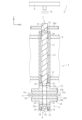
- FIG. 1 is a side view showing a glass plate cleaning device according to a first embodiment.
- 2 is a sectional view taken along line II in FIG. 1.
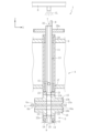
- FIG. FIG. 2 is an enlarged cross-sectional view showing the vicinity of one cleaning unit included in the glass plate cleaning apparatus of FIG. 1.
- FIG. 4 is a sectional view taken along line II-II in FIG. 3.
- FIG. 3 is an enlarged cross-sectional view showing the vicinity of one cleaning unit included in the glass plate cleaning apparatus according to the second embodiment.
- FIG. 3 is an enlarged cross-sectional view showing the vicinity of one cleaning unit included in the glass plate cleaning apparatus according to the third embodiment. It is a sectional view showing a glass plate cleaning device concerning a fourth embodiment.
- FIG. 8 is an enlarged perspective view showing the vicinity of the liquid guide member included in the glass plate cleaning device shown in FIG. 7; 8 is an enlarged cross-sectional view showing the vicinity of one cleaning unit included in the glass plate cleaning apparatus of FIG. 7.
- FIG. FIG. 7 is an enlarged cross-sectional view showing the vicinity of one cleaning unit included in the glass plate cleaning apparatus according to the fifth embodiment.
- FIG. 7 is an enlarged cross-sectional view showing the vicinity of one cleaning unit included in the glass plate cleaning apparatus according to the sixth embodiment.
- XYZ in the figure is an orthogonal coordinate system.
- the X direction and the Y direction are horizontal directions, and the Z direction is a vertical direction.
- Duplicate explanations may be omitted by assigning the same reference numerals to corresponding components in each embodiment.
- the configuration of the other embodiments previously described can be applied to other parts of the configuration.
- the glass plate cleaning apparatus 1 includes a pair of glass plates facing each other in the thickness direction of the glass plate G while conveying the glass plate G in a horizontal position in the conveying direction Y.
- the upper surface Ga and the lower surface Gb, which are the main surfaces, are simultaneously cleaned.
- the cleaning device 1 includes a cleaning area W and a drying area D.
- the upper surface Ga of the glass plate G is a guaranteed surface
- the lower surface Gb of the glass plate G is a non-guaranteed surface. Since electric circuits and the like are formed on the guarantee surface during the display manufacturing process, the cleanliness of the upper surface Ga of the glass plate G, which is the guarantee surface, is particularly important.
- the size of one side of the glass plate G is preferably 500 mm to 4000 mm, the plate thickness is preferably 0.05 mm to 10 mm, and more preferably 0.2 mm to 0.7 mm.
- the cleaning device 1 includes, in a cleaning area W, squeezing rollers 2 and 3 that remove liquid attached to the upper surface Ga and lower surface Gb of the glass plate G, an upper surface cleaning mechanism 4 that cleans the upper surface Ga of the glass plate G, and a glass plate G.
- a lower surface cleaning mechanism 5 that cleans the lower surface Gb of G, and a cleaning liquid supply section 6 that supplies cleaning liquid CL to the upper surface cleaning mechanism 4 are provided.
- a glass plate G is supplied to the cleaning area W by an arbitrary conveyance mechanism such as a roller arranged on the upstream side thereof.
- the squeezing rollers 2 and 3 also function as a transport mechanism that transports the glass plate G by sandwiching it between the upper and lower sides.
- the squeezing rollers 2 and 3 are constituted by a pair of upper and lower rollers including an upper roller and a lower roller.
- the squeezing rollers 2 and 3 are arranged upstream and downstream of the cleaning mechanisms 4 and 5, respectively.
- the upper surface cleaning mechanism 4 includes a plurality of cleaning units 7 that clean the upper surface Ga of the glass plate G, and a support body 8 that supports the plurality of cleaning units 7.
- the plurality of cleaning units 7 are arranged in a row along the width direction X perpendicular to the transport direction Y, and are provided in a plurality of rows (two rows in the illustrated example) in the transport direction Y.
- the lower surface cleaning mechanism 5 includes a plurality of cleaning units 9 that clean the lower surface Gb of the glass plate G, and a support body 10 that supports the plurality of cleaning units 9.
- the plurality of cleaning units 9 are arranged in a row along the width direction X perpendicular to the transport direction Y, and are provided in a plurality of rows (two rows in the illustrated example) in the transport direction Y.
- Each cleaning unit 9 of the lower surface cleaning mechanism 5 is arranged at a position corresponding to each cleaning unit 7 of the upper surface cleaning mechanism 4.
- the corresponding cleaning units 7 and 9 are configured to sandwich the glass plate G being transported from both upper and lower sides.
- the cleaning liquid supply section 6 is composed of a shower nozzle, and sprays and supplies the cleaning liquid CL toward the upper side of the upper rotating shaft 13, which will be described later.
- the cleaning liquid supply section 6 may spray and supply the cleaning liquid CL to the upper side of the upper rotating shaft 13 from above, or may supply the cleaning liquid CL to the upper side of the upper rotating shaft 13 from the lateral direction (including diagonally upward and downward). It may also be something that supplies it by injection.
- the cleaning liquid supply unit 6 is arranged above the upper surface cleaning mechanism 4 and the cleaning liquid CL is sprayed and supplied from above toward the upper end surface (upper end portion) of the upper rotating shaft 13 (falling supply).
- the cleaning liquid supply unit 6 is not limited to a shower nozzle, and any mechanism that can supply the cleaning liquid CL toward the upper side of the upper rotating shaft 13 can be adopted.
- a cleaning liquid for example, liquid detergent
- a rinsing liquid for example, water
- the supports 8 and 10 have a housing structure with an internal space.
- the cleaning liquid CL is not stored in the internal spaces of the supports 8 and 10.
- Each cleaning unit 7 of the upper surface cleaning mechanism 4 includes a shaft case 11 fixed to a support 8 and an upper rotating shaft 13 partially housed in the shaft case 11 (the middle portion excluding the upper end and the lower end). , an upper cleaning member 15 attached to the lower end of the upper rotating shaft 13 outside the support body 8 and the shaft case 11.
- Each cleaning unit 9 of the lower surface cleaning mechanism 5 includes a shaft case 12 fixed to a support 10, a lower rotating shaft 14 partially housed in the shaft case 12 (the middle portion excluding the upper end and the lower end). , a lower cleaning member 16 attached to the upper end of the lower rotating shaft 14 outside the support body 10 and the shaft case 12.
- each cleaning unit 7, 9 the corresponding rotating shaft 13, 14 and cleaning member 15, 16 rotate integrally.
- the shaft cases 11 and 12 are cylindrical members having a slightly larger diameter than the corresponding rotating shafts 13 and 14.
- the shaft cases 11 and 12 are inserted and fixed into holes provided in the upper and lower surfaces of the corresponding supports 8 and 10, respectively.
- the sliding bearings 17 to 20 may be made of metal, for example, but in this embodiment, they are made of resin (for example, thermoplastic resin, thermosetting resin, etc.).
- the upper cleaning member 15 is removable from the upper rotating shaft 13.
- the upper cleaning member 15 includes a cleaning section 15a that comes into contact with the upper surface Ga of the glass plate G to clean it, and a support section 15b that supports the cleaning section 15a.
- the lower cleaning member 16 is removable from the lower rotating shaft 14.
- the lower cleaning member 16 includes a cleaning section 16a that contacts and cleans the lower surface Gb of the glass plate G, and a support section 16b that supports the cleaning section 16a.
- the cleaning parts 15a and 16a may be, for example, brushes, but in this embodiment they are sponges. Although the shape of the cleaning portions 15a and 16a is not particularly limited, in this embodiment, it is disk-shaped.
- the upper rotating shaft 13 includes an upper cleaning liquid supply path 21 in the center (inside) through which the cleaning liquid CL flows.
- the upper cleaning liquid supply path 21 includes an inlet 21a that allows the cleaning liquid CL to flow into the upper cleaning liquid supply path 21 above the upper rotating shaft 13, and an inlet 21a that allows the cleaning liquid CL to flow into the upper cleaning liquid supply path 21 at the upper side of the upper rotating shaft 13, and an inlet 21a that allows the cleaning liquid CL to flow into the upper cleaning liquid supply path 21 at a lower side than the inlet 21a of the upper rotating shaft 13. and an outlet 21b through which the cleaning liquid CL flows out.
- the lower rotating shaft 14 includes a lower cleaning liquid supply path 22 in the center (inside) through which the cleaning liquid CL flows.
- the lower cleaning liquid supply path 22 includes an inlet 22a that allows cleaning liquid CL to flow into the lower cleaning liquid supply path 22 above the lower rotating shaft 14, and an inlet 22a that allows the cleaning liquid CL to flow into the lower cleaning liquid supply path 22 at the upper side of the lower rotating shaft 14, and an inlet 22a that allows the cleaning liquid CL to flow into the lower cleaning liquid supply path 22 at a lower side than the inlet 22a of the lower rotating shaft 14. and an outlet 22b through which the cleaning liquid CL flows out.
- the cleaning liquid supply paths 21 and 22 linearly penetrate the corresponding rotating shafts 13 and 14 in the vertical direction Z. That is, the inflow ports 21a and 22a are provided on the upper end surfaces (upper end portions) of the corresponding rotating shafts 13 and 14, and the outlet ports 21b and 22b are provided on the lower end surfaces (lower end portions) of the corresponding rotating shafts 13 and 14. It is being
- the upper cleaning member 15 has a supply hole 23 in the center (inside) that communicates with the outlet 21b of the upper cleaning liquid supply path 21 and penetrates in the vertical direction Z.
- the lower cleaning member 16 communicates with the inlet 22a of the lower cleaning liquid supply path 22, and has a supply hole 24 in the vertical direction Z in the center (inside).
- the supply holes 23 and 24 may be omitted when the cleaning members 15 and 16 are made of a material (for example, a porous material) that allows the cleaning liquid CL to pass therethrough.
- the upper cleaning member 15 and the lower cleaning member 16 have overlapping parts that overlap each other when viewed from the vertical direction.
- the upper cleaning member 15 and the lower cleaning member 16 are arranged on a concentric axis, and the area of the overlapping portion is substantially equal to the cleaning surface of the upper cleaning member 15 (or the cleaning surface of the lower cleaning member 16).
- the area is essentially the same.
- the area of the overlapping portion is preferably 70% or more, 80% or more, 90% or more, or 95% to 100% of the area of the cleaning surface of the upper cleaning member 15 (or the cleaning surface of the lower cleaning member 16).
- the cleaning liquid CL dropped and supplied from the cleaning liquid supply section 6 arranged above the upper surface cleaning mechanism 4 flows into the upper cleaning liquid supply path 21 from the inlet 21a.
- the cleaning liquid CL that has flowed into the upper cleaning liquid supply path 21 moves downward within the upper cleaning liquid supply path 21, flows out of the upper cleaning liquid supply path 21 from the outlet 21b, and is supplied to the supply hole 23 of the upper cleaning member 15. Ru.
- the cleaning liquid CL supplied to the supply hole 23 is supplied to the glass plate G when the glass plate G is present between the upper cleaning member 15 and the lower cleaning member 16. Therefore, the cleaning liquid CL can be sufficiently supplied to the upper cleaning member 15 and the glass plate G through the upper cleaning liquid supply path 21, and the occurrence of uneven cleaning on the glass plate G can be suppressed.
- the cleaning liquid CL is supplied to the lower cleaning member 16 of the lower surface cleaning mechanism 5 through the supply hole 23 of the upper cleaning member 15 in a state where there is no glass plate G between the upper cleaning member 15 and the lower cleaning member 16. .
- the cleaning liquid CL supplied to the lower cleaning member 16 flows into the lower cleaning liquid supply path 22 from the inlet 22a through the supply hole 24.
- the cleaning liquid CL that has flowed into the lower cleaning liquid supply path 22 moves downward within the lower cleaning liquid supply path 22, flows out of the lower cleaning liquid supply path 22 from the outlet 22b, and is discharged to the outside.
- the upper cleaning member 15 descends under its own weight and comes into contact with the lower cleaning member 16. Therefore, as described above, when supplying the cleaning liquid CL from the upper surface cleaning mechanism 4 to the lower surface cleaning mechanism 5 without the glass plate G, the supply holes 23 and 24 of the upper and lower cleaning members 15 and 16 are in contact with each other. Communicate in the state.
- the upper surface cleaning mechanism 4 includes a rotational drive mechanism 25 that rotationally drives the upper rotating shaft 13 of each cleaning unit 7.
- the rotational drive mechanism 25 is configured to apply rotational driving force to the upper side of the upper rotating shaft 13 outside the support body 8 and the shaft case 11.
- the rotational drive mechanism 25 includes a motor 27 and a gear mechanism 29 including a plurality of gears 29a that transmits the rotational driving force of the motor 27 to each upper rotation shaft 13.
- the lower surface cleaning mechanism 5 includes a rotational drive mechanism 26 that rotationally drives the lower rotating shaft 14 of each cleaning unit 9.
- the rotational drive mechanism 26 is configured to apply rotational driving force to the lower side of the lower rotating shaft 14 outside the support body 10 and the shaft case 12.
- the rotational drive mechanism 26 includes a motor 28 and a gear mechanism 30 including a plurality of gears 30a that transmits the rotational driving force of the motor 28 to each lower rotation shaft 14.
- a dedicated rotation drive mechanism 25, 26 is provided for each row of cleaning units 7, 9 provided in multiple rows in the transport direction Y.
- the upper rotating shaft 13 has a through hole 31 as a penetrating portion for supplying the cleaning liquid CL from the internal upper cleaning liquid supply path 21 to the external sliding bearing 19. .
- the through hole 31 supplies the cleaning liquid CL to the sliding bearing 19 provided at the upper end of the shaft case 11.
- the through hole 31 is a horizontal hole that penetrates in the radial direction between the inner circumferential surface 13 a and the outer circumferential surface 13 b of the upper rotating shaft 13 , and is provided at a height corresponding to the upper end of the sliding bearing 19 .
- the formation range of the through hole 31 in the Z-axis direction spans both upper and lower sides of the upper end surface of the sliding bearing 19.
- the formation range of the through hole 31 is not particularly limited, and may be above the upper end of the sliding bearing 19 or below the upper end of the sliding bearing 19 (for example, at the upper end of the sliding bearing 19). and the lower end).
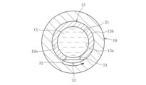
- the outer peripheral surface 13b of the upper rotating shaft 13 has a notch 32 that is continuously formed from the upper end to the lower end of the upper rotating shaft 13.
- the notch 32 has a linear shape extending in the vertical direction Z, and when the upper rotating shaft 13 is stopped, the circumferential position of the notch 32 is from the upper end to the lower end of the upper rotating shaft 13. does not change between
- the portion of the outer circumferential surface 13b of the upper rotating shaft 13 in which the notch 32 is formed is separated inward from the inner circumferential surface 19a of the sliding bearing 19. Therefore, the notch 32 forms a space 33 between the outer circumferential surface 13b of the upper rotating shaft 13 and the inner circumferential surface 19a of the sliding bearing 19.
- a through hole 31 is formed in the notch 32, and the upper cleaning liquid supply path 21 and the space 33 communicate with each other via the through hole 31.
- the cleaning liquid CL in the upper cleaning liquid supply path 21 is efficiently supplied between the upper rotating shaft 13 and the sliding bearing 19 through the through hole 31. Furthermore, since the positions of the through hole 31 and the notch 32 change in the circumferential direction as the upper rotating shaft 13 rotates, the cleaning liquid CL is evenly supplied between the upper rotating shaft 13 and the sliding bearing 19. be done. Therefore, the frictional heat generated between the upper rotating shaft 13 and the sliding bearing 19 can be reduced, and wear of the upper rotating shaft 13 and/or the sliding bearing 19 can be suppressed. Note that a part of the cleaning liquid CL supplied from the cleaning liquid supply section 6 flows directly between the upper rotating shaft 13 and the sliding bearing 19 from the upper end opening of the space 33 without passing through the upper cleaning liquid supply path 21 . Such cleaning liquid CL also has the effect of reducing the frictional heat generated between the upper rotating shaft 13 and the sliding bearing 19.
- the cleaning liquid CL supplied between the upper rotating shaft 13 and the upper sliding bearing 19 is discharged downward through the notch 32 (space 33).
- the cleaning liquid CL discharged from the notch 32 moves downward between the upper rotating shaft 13 and the shaft case 11 and between the upper rotating shaft 13 and the lower sliding bearing 17 (formed by the notch 32). (the space between the upper rotating shaft 13 and the sliding bearing 17).
- the cleaning liquid CL supplied between the upper rotating shaft 13 and the lower sliding bearing 17 is discharged downward through the notch 32 (space). That is, the cleaning liquid CL does not stay between the upper rotating shaft 13 and the shaft case 11.
- the notch 32 is not limited to the case where it is formed continuously from the upper end to the lower end of the upper rotating shaft 13 on the outer circumferential surface 13b of the upper rotating shaft 13.
- the notch portion 32 is located at a height position corresponding to the sliding bearing 17 and/or the sliding bearing 19 on the outer circumferential surface 13b of the upper rotating shaft 13 (preferably, a position that includes the entire upper and lower areas of the sliding bearings 17 and 19). It may also be formed only in one piece. However, from the viewpoint of workability, it is preferable that the notch portion 32 is continuously formed over the entire length of the outer circumferential surface 13b of the upper rotating shaft 13 in the upper and lower directions.
- the lower rotating shaft 14 has a through hole (penetrating portion) 34 that communicates between the lower cleaning liquid supply path 22 and the sliding bearing 18 provided at the upper end of the shaft case 12. and a notch 35 that is continuously formed from the upper end to the lower end of the lower rotating shaft 14.
- the through hole 34 is formed in a notch 35 .
- the functions of the through hole 34 and the notch 35 are the same as those of the through hole 31 and the notch 32 in the upper surface cleaning mechanism 4 described above.
- the cleaning device 1 includes an air knife 36 and a conveyance roller 37 in the drying area D.
- the air knives 36 are arranged on both sides of the conveyance roller 37, both above and below.
- the drying area D While the glass plate G is being conveyed by the conveyance roller 37, high-pressure air AG is injected from the air knife 36 onto the upper surface Ga and lower surface Gb of the glass plate G, thereby removing moisture adhering to these surfaces. .
- the glass plate G may be dried by a known drying means other than the air knife 36. Further, the drying area D may be omitted.
- This manufacturing method includes, for example, a molding process, an annealing process, a board sampling process, a cutting process, a cleaning process, an inspection process, and a packaging process.
- a glass ribbon is formed from molten glass by a known method such as an overflow down-draw method or a float method.
- the shaped glass ribbon is slowly cooled in order to reduce warpage and internal distortion of the shaped glass ribbon.
- the slowly cooled glass ribbon is cut into predetermined lengths to obtain a plurality of original glass plates.
- the original glass plate is cut into a predetermined size to obtain one or more glass plates G.
- a method for cutting the original glass plate for example, bending stress cutting, laser cutting, laser fusing, etc. can be used. It is preferable that the glass plate G has a rectangular shape.
- the above-mentioned cleaning device 1 is used to clean the glass plate G while being conveyed in a horizontal position.
- the cleaning liquid CL supplied from the cleaning liquid supply section 6 is sufficiently supplied to the cleaning members 7 and 9 through the upper cleaning liquid supply path 21, so that uneven cleaning does not occur on the upper surface Ga and lower surface Gb of the glass plate G. can be suppressed.
- the cleaned glass plate G is inspected for scratches, dust, dirt, etc. on the surface and/or for internal defects such as air bubbles and foreign objects.
- the inspection is performed using an optical inspection device such as a camera.
- glass plates G that satisfy the desired quality as a result of the inspection are packed.
- Packing is performed by stacking a plurality of glass plates G horizontally or vertically on a predetermined pallet.
- a protective sheet made of paper, foamed resin, or the like between the glass plates G in the stacking direction.
- the present manufacturing method may further include a heat treatment step after the plate sampling step, and an end face processing step after the cutting step.
- the through hole 41 is provided in the notch 32 at a height corresponding to the upper end of the sliding bearing 17.
- the formation range of the through hole 41 in the Z direction extends over both upper and lower sides of the upper end surface of the sliding bearing 17.
- the formation range of the through hole 41 is not particularly limited, and may be above the upper end of the sliding bearing 17 or below the upper end of the sliding bearing 17 (for example, at the upper end of the sliding bearing 17). and the lower end).
- the upper rotating shaft 13 has a through hole 31 (see FIG. 3) that communicates the upper cleaning liquid supply path 21 with a sliding bearing 19 provided at the upper end of the shaft case 11, and a through hole 31 (see FIG. Each of them may be provided with a through hole 41 (see FIG. 5) that communicates with the sliding bearing 17 provided at the lower end.
- the lower rotating shaft 14 has a through hole (not shown) that communicates the lower cleaning liquid supply path 22 with the sliding bearing 20 provided at the lower end of the shaft case 12. You may be prepared.
- the outer peripheral surface of the lower rotating shaft 14 has a spiral notch that is continuously formed from the upper end to the lower end of the lower rotating shaft 14.
- a section 52 is provided. The function of the notch 52 is similar to that of the notch 51 in the upper surface cleaning mechanism 4 described above.
- the glass plate cleaning device 1 according to the fourth embodiment is different from the glass plate cleaning device 1 according to the first embodiment in that a liquid guide member R is further provided. be.
- the liquid guiding member R is disposed between the upper rotating shaft 13 and the cleaning liquid supply section 6, and is for guiding the cleaning liquid CL supplied from the cleaning liquid supply section 6 to the inlet 21a of the upper cleaning liquid supply path 21. .
- the liquid guiding member R is provided on the upper end surface of the upper rotating shaft 13 and is rotatable together with the upper rotating shaft 13.
- the liquid guide member R is a plate-like member that extends upward from the inlet 21 a of the upper cleaning liquid supply path 21 and is capable of receiving the cleaning liquid CL supplied from the cleaning liquid supply section 6 .
- liquid guiding member R is a separate item adhered to the upper end surface of the upper rotating shaft 13 by welding, the liquid guiding member R and the upper rotating shaft 13 may be integrated.
- the liquid guide member R has the same thickness as the wall of the upper rotating shaft 13.
- the liquid guiding member R has a shape (for example, a partially cylindrical shape such as a semi-cylindrical shape) that follows the periphery of the upper end surface of the upper rotating shaft 13 (the outline of the inlet 21a).
- the liquid guiding member R is provided only on a part of the upper end surface of the upper rotating shaft 13 in the circumferential direction. That is, the upper end surface of the upper rotating shaft 13 has a portion where the liquid guiding member R is not provided.
- the cleaning liquid CL that hits the liquid guide member R and is collected is guided to the inlet 21a of the upper cleaning liquid supply path 21 and is supplied into the upper cleaning liquid supply path 21. Therefore, the cleaning liquid CL can be efficiently guided into the upper cleaning liquid supply path 21.
- a part of the cleaning liquid CL that hits the liquid guide member R and is collected is scattered to the surrounding area through the part where the liquid guide member R is not provided due to the centrifugal force caused by the rotation of the upper rotating shaft 13. , gear 29a, etc. As a result, the lubricity of gear 29a and the like becomes better.
- liquid guide member R is provided in a range of 20 to 80% of the entire circumference of the upper end of the upper rotating shaft 13.
- the glass plate cleaning device 1 according to the fourth embodiment is obtained by applying a liquid guide member R to the glass plate cleaning device 1 according to the second embodiment.
- the glass plate cleaning device 1 according to the fifth embodiment is obtained by applying a liquid guiding member R to the glass plate cleaning device 1 according to the third embodiment.
- the position of the inlet is not limited to this.
- the inlet of the upper cleaning liquid supply path may be provided on the circumferential surface (side surface) of the upper rotating shaft as long as it is above the upper rotating shaft.
- the inlet of the upper cleaning liquid supply path is formed by a horizontal hole passing through between the inner circumferential surface and the outer circumferential surface of the upper rotating shaft. That is, the upper end surface of the upper rotating shaft may be closed. It is preferable that the inlet of the upper cleaning liquid supply path is formed within a range of 1 ⁇ 3 of the total height from the top of the upper rotating shaft.
- the inlet of the upper cleaning liquid supply path is preferably provided in a portion of the upper rotating shaft that is exposed to the outside of the support and the shaft case. Further, it is preferable that the inlet of the upper cleaning liquid supply path be provided in a portion of the upper rotating shaft located above the gear of the rotational drive mechanism. Note that similar modifications can be applied to the inlet of the lower cleaning liquid supply path. In other words, the inlet of the lower cleaning liquid supply path is not limited to being provided on the upper end surface of the lower rotating shaft as long as it is above the lower rotating shaft. (within 1/3 of the total height from the top).
- the outlet of the upper cleaning liquid supply path is provided on the lower end surface of the upper rotating shaft, but the position of the outlet is not limited to this.
- the outlet of the upper cleaning liquid supply path may be provided on the circumferential surface (side surface) of the upper rotating shaft as long as it is below the upper rotating shaft.
- the outlet of the upper cleaning liquid supply path is formed by a horizontal hole passing through between the inner circumferential surface and the outer circumferential surface of the upper rotating shaft. That is, the lower end surface of the upper rotating shaft may be closed.
- the outlet of the upper cleaning liquid supply path is preferably formed within a range of 1 ⁇ 3 of the total height from the bottom of the upper rotating shaft.
- the outlet of the upper cleaning liquid supply path is preferably provided in a portion of the upper rotating shaft that is exposed to the outside of the support and the shaft case. Note that similar modifications can be applied to the outlet of the lower cleaning liquid supply path.
- the outlet of the lower cleaning liquid supply path is not limited to being provided on the lower end surface of the lower rotating shaft as long as it is located below the lower rotating shaft. (within 1/3 of the total height from the bottom).
- a notch and a through hole are provided at one location in the circumferential direction of the outer circumferential surface of the rotating shaft. They may be provided at multiple locations in the direction. Specifically, for example, notches extending vertically in a straight line may be provided at multiple locations in the circumferential direction of the rotating shaft, and through holes may be provided in each of the notches at a height corresponding to the sliding bearing. good.
- the through hole is provided in the notch, but the through hole may be provided in a portion other than the notch. Moreover, either one of the through hole and the notch portion may be omitted.
- the through hole that communicates the cleaning liquid supply path and the bearing is a through hole, but the through hole may be a slit or the like extending along a notch.
- the notch formed on the outer circumferential surface of the rotating shaft of the upper surface cleaning mechanism and the notch formed on the outer circumferential surface of the rotating shaft of the lower surface cleaning mechanism have the same shape. Although described above, both may have different shapes (for example, one notch may be linear, the other notch may be spiral, etc.).
- the cleaning member may be moved relative to the glass plate placed in a fixed position, or both the glass plate and the cleaning member may be moved.
- the glass plate when cleaning and transporting the glass plate, may be inclined such that one end side is located lower than the other end side in the width direction perpendicular to the transport direction. This can prevent excess liquid adhering to the top surface of the glass plate from flowing down from the top surface of the glass plate under its own weight, thereby preventing the formation of a liquid pool on the top surface of the glass plate that causes stains.
- the liquid guiding member provided on the upper end surface of the upper rotating shaft has a shape (for example, a partially cylindrical shape such as a semi-cylindrical shape) that follows the periphery of the upper end surface of the upper rotating shaft (outline of the inlet 21a).
- a shape of the liquid guiding member is not limited to this, the shape of the liquid guiding member is not limited to this.
- the liquid guide member may have, for example, a tapered shape or a funnel shape that increases in diameter as it moves upward away from the upper end surface of the upper rotating shaft.
- the liquid guiding member is provided on the upper end surface of the upper rotating shaft and rotates integrally with the upper rotating shaft, but the position of the liquid guiding member is the inlet of the upper cleaning liquid supply path. It can be changed as appropriate within a range that allows the cleaning solution to be guided.
- the liquid guiding member may be provided on the peripheral surface (side surface) of the upper rotating shaft.
- the liquid guiding member may be fixed at a position apart from the upper rotating shaft. That is, the liquid guiding member may be configured not to rotate integrally with the upper rotating shaft.
- the cleaning liquid supply section sprays and supplies cleaning liquid from the lateral direction of the upper end of the upper rotating shaft
- no liquid guiding member is provided on the front side of the upper cleaning liquid supply path in the cleaning liquid injection supply direction, and the upper cleaning liquid is supplied. It is preferable to provide the liquid guide member on the back side across the path.
- the inlet of the upper cleaning liquid supply path is provided on the upper peripheral surface (side surface) of the upper rotating shaft, it is preferable to adjust the position and shape of the liquid guide member according to the position of the inlet.
Landscapes
- Chemical & Material Sciences (AREA)
- Life Sciences & Earth Sciences (AREA)
- Engineering & Computer Science (AREA)
- Chemical Kinetics & Catalysis (AREA)
- General Chemical & Material Sciences (AREA)
- Geochemistry & Mineralogy (AREA)
- Materials Engineering (AREA)
- Organic Chemistry (AREA)
- Cleaning By Liquid Or Steam (AREA)
- Surface Treatment Of Glass (AREA)
Abstract
Description
図1及び図2に示すように、第一実施形態に係るガラス板の洗浄装置1は、水平姿勢のガラス板Gを搬送方向Yに搬送しながら、ガラス板Gの板厚方向に対向する一対の主表面である上面Ga及び下面Gbを同時に洗浄するものである。洗浄装置1は、洗浄エリアWと、乾燥エリアDとを備える。
図5に示すように、第二実施形態に係るガラス板の洗浄装置1は、上面洗浄機構4において、上回転シャフト13が、上洗浄液供給路21とシャフトケース11の下端部に設けられた滑り軸受17とを連通する貫通孔(貫通部)41を備える。
図6に示すように、第三実施形態に係るガラス板の洗浄装置1は、上面洗浄機構4において、上回転シャフト13の外周面が、上回転シャフト13の上端部から下端部まで連続的に形成された螺旋状の切欠き部51を備える。このようにすれば、上回転シャフト13を停止させた状態でも、切欠き部51の周方向位置が、上回転シャフト13の上端部から下端部に至るまでの間で連続的に変化する。このようにすれば、上回転シャフト13に切欠き部51を形成しても、回転バランスが悪化し難いという利点がある。
図7~図9に示すように、第四実施形態に係るガラス板の洗浄装置1は、第一実施形態に係るガラス板の洗浄装置1に対して、さらに導液部材Rを設けたものである。
図10に示すように、第四実施形態に係るガラス板の洗浄装置1は、第二実施形態に係るガラス板の洗浄装置1に対して、導液部材Rを適用したものである。
図11に示すように、第五実施形態に係るガラス板の洗浄装置1は、第三実施形態に係るガラス板の洗浄装置1に対して、導液部材Rを適用したものである。
4 上面洗浄機構
5 下面洗浄機構
6 洗浄液供給部
7,9 洗浄ユニット
8,10 支持体
11,12 シャフトケース
13,14 回転シャフト
15,16 洗浄部材
17~20 滑り軸受
21,22 洗浄液供給路
23,24 供給孔
25,26 回転駆動機構
27,28 モータ
29,30 ギア機構
31,34,41 貫通孔
32,35,51,52 切欠き部
33 空間
34,41 貫通孔
G ガラス板
W 洗浄エリア
D 乾燥エリア
CL 洗浄液
AG 高圧エア
R 導液部材
Claims (23)
- 上回転シャフトと、前記上回転シャフトの下端部に設けられ、ガラス板の上面を洗浄する上洗浄部材とを有する上面洗浄機構を備えたガラス板の洗浄装置において、
前記上回転シャフトの上側に対して洗浄液を供給する洗浄液供給部を備え、
前記上回転シャフトは、前記洗浄液を流通させる上洗浄液供給路を内部に備え、
前記上洗浄液供給路は、前記上回転シャフトの上側で前記上洗浄液供給路内に前記洗浄液を流入させる流入口と、前記上回転シャフトの前記流入口よりも下側で前記上洗浄液供給路外に前記洗浄液を流出させて前記上洗浄部材に供給する流出口とを備えることを特徴とするガラス板の洗浄装置。 - 前記上回転シャフトを回転可能に支持する軸受を備え、
前記上回転シャフトは、前記上洗浄液供給路から前記軸受に前記洗浄液を供給する貫通部を有する請求項1に記載のガラス板の洗浄装置。 - 前記貫通部が、前記軸受の上端部に対応する高さ位置に設けられている請求項2に記載のガラス板の洗浄装置。
- 前記上回転シャフトの外周面は、前記軸受に対応する高さ位置において、切欠き部を有する請求項2に記載のガラス板の洗浄装置。
- 前記貫通部が、前記切欠き部に設けられている請求項4に記載のガラス板の洗浄装置。
- 前記切欠き部が、前記上回転シャフトの上端部から下端部まで連続的に形成されている請求項4又は5に記載のガラス板の洗浄装置。
- 前記上回転シャフトを回転可能に支持する軸受を備え、
前記上回転シャフトの外周面は、前記軸受に対応する高さ位置において、切欠き部を有する請求項1に記載のガラス板の洗浄装置。 - 前記切欠き部が、前記上回転シャフトの上端部から下端部まで連続的に形成されている請求項7に記載のガラス板の洗浄装置。
- 前記上回転シャフトの少なくとも一部を内部に収容するシャフトケースを備え、前記軸受は、前記シャフトケースの内周面と前記上回転シャフトの外周面との間に設けられている請求項2又は7に記載のガラス板の洗浄装置。
- 前記流入口が、前記上回転シャフトの上端面に設けられている請求項1に記載のガラス板の洗浄装置。
- 前記流出口が、前記上回転シャフトの下端面に設けられている請求項1に記載のガラス板の洗浄装置。
- 前記洗浄液を前記上洗浄液供給路の前記流入口に誘導する導液部材を備える請求項1~5、7、8、10、11のいずれか1項に記載のガラス板の洗浄装置。
- 前記導液部材は、前記上回転シャフトに設けられ、前記上回転シャフトと共に回転可能である請求項12に記載のガラス板の洗浄装置。
- 前記流入口が、前記上回転シャフトの上端面に設けられ、
前記導液部材が、前記上回転シャフトの上端部に設けられている請求項13に記載のガラス板の洗浄装置。 - 前記導液部材は、前記上回転シャフトの周方向の一部のみに設けられている請求項14に記載のガラス板の洗浄装置。
- 前記導液部材は、前記上回転シャフトの全周の20~80%の範囲に設けられている請求項15に記載のガラス板の洗浄装置。
- 前記導液部材は、前記上回転シャフトの周囲に倣った形状である請求項14に記載のガラス板の洗浄装置。
- 下回転シャフトと、前記下回転シャフトの上端部に設けられ、前記ガラス板の下面を洗浄する下洗浄部材とを有する下面洗浄機構を備え、
前記上洗浄部材及び前記下洗浄部材は、前記洗浄液が通過可能であり、かつ、上下方向からみて互いに重なる重複部を有する請求項1~5、7、8、10、11のいずれか1項に記載のガラス板の洗浄装置。 - 前記下回転シャフトは、前記洗浄液を流通させる下洗浄液供給路を内部に備え、
前記下洗浄液供給路は、前記下回転シャフトの上側で前記下洗浄液供給路内に前記洗浄液を流入させる流入口と、前記下回転シャフトの前記流入口よりも下側で前記下洗浄液供給路外に前記洗浄液を流出させる流出口とを備える請求項18に記載のガラス板の洗浄装置。 - 前記上洗浄部材及び前記下洗浄部材は、同軸上に配置されている請求項18に記載のガラス板の洗浄装置。
- 前記上洗浄部材及び前記下洗浄部材は、前記ガラス板がある場合に互いに離間し、前記ガラス板がない場合に互いに接触するように移動可能に構成されている請求項18に記載のガラス板の洗浄装置。
- 回転シャフトと、前記回転シャフトの下端部に設けられた洗浄部材とを備えたガラス板の洗浄装置において、
前記回転シャフトは、上下に貫通する洗浄液供給路を内部に備え、
前記洗浄液供給路は、前記回転シャフトの上端部に設けられ、洗浄液供給部から供給される洗浄液が流入する流入口と、前記回転シャフトの下端部に設けられ、前記流入口から流入した前記洗浄液を流出する流出口とを備えることを特徴とするガラス板の洗浄装置。 - 請求項1~5、7、8、10、11、22のいずれか1項に記載のガラス板の洗浄装置を用いて、ガラス板を洗浄する洗浄工程を備えることを特徴とするガラス板の製造方法。
Priority Applications (2)
| Application Number | Priority Date | Filing Date | Title |
|---|---|---|---|
| CN202380028366.7A CN118843609A (zh) | 2022-05-02 | 2023-04-27 | 玻璃板的清洗装置以及玻璃板的制造方法 |
| JP2024519206A JPWO2023214539A1 (ja) | 2022-05-02 | 2023-04-27 |
Applications Claiming Priority (4)
| Application Number | Priority Date | Filing Date | Title |
|---|---|---|---|
| JP2022-076071 | 2022-05-02 | ||
| JP2022076071 | 2022-05-02 | ||
| JP2022129659 | 2022-08-16 | ||
| JP2022-129659 | 2022-08-16 |
Publications (1)
| Publication Number | Publication Date |
|---|---|
| WO2023214539A1 true WO2023214539A1 (ja) | 2023-11-09 |
Family
ID=88646477
Family Applications (1)
| Application Number | Title | Priority Date | Filing Date |
|---|---|---|---|
| PCT/JP2023/016718 Ceased WO2023214539A1 (ja) | 2022-05-02 | 2023-04-27 | ガラス板の洗浄装置及びガラス板の製造方法 |
Country Status (3)
| Country | Link |
|---|---|
| JP (1) | JPWO2023214539A1 (ja) |
| TW (1) | TW202348317A (ja) |
| WO (1) | WO2023214539A1 (ja) |
Citations (4)
| Publication number | Priority date | Publication date | Assignee | Title |
|---|---|---|---|---|
| JP2002096037A (ja) * | 2000-09-22 | 2002-04-02 | Tokyo Electron Ltd | 基板洗浄具及び基板洗浄装置 |
| KR20050000477A (ko) * | 2003-06-27 | 2005-01-05 | 태화일렉트론(주) | 평판디스플레이 글라스 세정용 디스크 브러쉬의 구동구조 |
| WO2011126028A1 (ja) * | 2010-04-08 | 2011-10-13 | 旭硝子株式会社 | ガラス板の製造方法及び製造装置 |
| WO2020012863A1 (ja) * | 2018-07-10 | 2020-01-16 | 日本電気硝子株式会社 | ガラス板の製造方法およびガラス板の洗浄装置 |
-
2023
- 2023-04-27 WO PCT/JP2023/016718 patent/WO2023214539A1/ja not_active Ceased
- 2023-04-27 JP JP2024519206A patent/JPWO2023214539A1/ja active Pending
- 2023-04-28 TW TW112115952A patent/TW202348317A/zh unknown
Patent Citations (4)
| Publication number | Priority date | Publication date | Assignee | Title |
|---|---|---|---|---|
| JP2002096037A (ja) * | 2000-09-22 | 2002-04-02 | Tokyo Electron Ltd | 基板洗浄具及び基板洗浄装置 |
| KR20050000477A (ko) * | 2003-06-27 | 2005-01-05 | 태화일렉트론(주) | 평판디스플레이 글라스 세정용 디스크 브러쉬의 구동구조 |
| WO2011126028A1 (ja) * | 2010-04-08 | 2011-10-13 | 旭硝子株式会社 | ガラス板の製造方法及び製造装置 |
| WO2020012863A1 (ja) * | 2018-07-10 | 2020-01-16 | 日本電気硝子株式会社 | ガラス板の製造方法およびガラス板の洗浄装置 |
Also Published As
| Publication number | Publication date |
|---|---|
| JPWO2023214539A1 (ja) | 2023-11-09 |
| TW202348317A (zh) | 2023-12-16 |
Similar Documents
| Publication | Publication Date | Title |
|---|---|---|
| KR102566215B1 (ko) | 유리판의 세정장치 및 유리판의 제조방법 | |
| TWI554461B (zh) | 玻璃板搬運裝置及其搬運方法 | |
| JP5512799B2 (ja) | 平面的な被処理材料を処理するための方法、処理ステーションおよびアセンブリ | |
| JP6315547B2 (ja) | 基板処理装置 | |
| JP2010114123A (ja) | 基板処理装置及び基板洗浄方法 | |
| JP2021113132A (ja) | ガラス板の製造方法及びガラス板の洗浄装置 | |
| TW202348317A (zh) | 玻璃板的清洗裝置及玻璃板的製造方法 | |
| CN111640692B (zh) | 一种晶圆的清洗辅助装置及清洗装置 | |
| CN118843609A (zh) | 玻璃板的清洗装置以及玻璃板的制造方法 | |
| JP7081351B2 (ja) | ガラス板の製造方法およびガラス板の洗浄装置 | |
| JP4206359B2 (ja) | 処理液供給装置 | |
| KR101092750B1 (ko) | 기판 건조 장치 | |
| JP2008270284A (ja) | 基板の処理装置 | |
| WO2020255828A1 (ja) | ガラス板の製造方法及びガラス板の洗浄装置 | |
| JP2023073736A (ja) | ガラス板の洗浄装置及びガラス板の製造方法 | |
| JP2012214323A (ja) | シートガラスの製造方法および洗浄ブラシ体 | |
| JP2006239503A (ja) | 基板の処理装置 | |
| JP7839017B2 (ja) | ウェーハ洗浄装置 | |
| JP2003305415A (ja) | 基板の処理装置及び処理方法 | |
| WO2022202224A1 (ja) | ガラス板の製造方法 | |
| KR20100027423A (ko) | 습식 에칭장치 | |
| JP2012245191A (ja) | 遊技球研磨装置 |
Legal Events
| Date | Code | Title | Description |
|---|---|---|---|
| 121 | Ep: the epo has been informed by wipo that ep was designated in this application |
Ref document number: 23799469 Country of ref document: EP Kind code of ref document: A1 |
|
| ENP | Entry into the national phase |
Ref document number: 2024519206 Country of ref document: JP Kind code of ref document: A |
|
| WWE | Wipo information: entry into national phase |
Ref document number: 202380028366.7 Country of ref document: CN |
|
| NENP | Non-entry into the national phase |
Ref country code: DE |
|
| 122 | Ep: pct application non-entry in european phase |
Ref document number: 23799469 Country of ref document: EP Kind code of ref document: A1 |