WO2023210635A1 - 鉛蓄電池 - Google Patents
鉛蓄電池 Download PDFInfo
- Publication number
- WO2023210635A1 WO2023210635A1 PCT/JP2023/016277 JP2023016277W WO2023210635A1 WO 2023210635 A1 WO2023210635 A1 WO 2023210635A1 JP 2023016277 W JP2023016277 W JP 2023016277W WO 2023210635 A1 WO2023210635 A1 WO 2023210635A1
- Authority
- WO
- WIPO (PCT)
- Prior art keywords
- lead
- battery case
- plate group
- cross
- electrode plate
- Prior art date
- Legal status (The legal status is an assumption and is not a legal conclusion. Google has not performed a legal analysis and makes no representation as to the accuracy of the status listed.)
- Ceased
Links
Images
Classifications
-
- H—ELECTRICITY
- H01—ELECTRIC ELEMENTS
- H01M—PROCESSES OR MEANS, e.g. BATTERIES, FOR THE DIRECT CONVERSION OF CHEMICAL ENERGY INTO ELECTRICAL ENERGY
- H01M4/00—Electrodes
- H01M4/02—Electrodes composed of, or comprising, active material
- H01M4/14—Electrodes for lead-acid accumulators
-
- H—ELECTRICITY
- H01—ELECTRIC ELEMENTS
- H01M—PROCESSES OR MEANS, e.g. BATTERIES, FOR THE DIRECT CONVERSION OF CHEMICAL ENERGY INTO ELECTRICAL ENERGY
- H01M10/00—Secondary cells; Manufacture thereof
- H01M10/06—Lead-acid accumulators
-
- H—ELECTRICITY
- H01—ELECTRIC ELEMENTS
- H01M—PROCESSES OR MEANS, e.g. BATTERIES, FOR THE DIRECT CONVERSION OF CHEMICAL ENERGY INTO ELECTRICAL ENERGY
- H01M10/00—Secondary cells; Manufacture thereof
- H01M10/06—Lead-acid accumulators
- H01M10/12—Construction or manufacture
-
- H—ELECTRICITY
- H01—ELECTRIC ELEMENTS
- H01M—PROCESSES OR MEANS, e.g. BATTERIES, FOR THE DIRECT CONVERSION OF CHEMICAL ENERGY INTO ELECTRICAL ENERGY
- H01M50/00—Constructional details or processes of manufacture of the non-active parts of electrochemical cells other than fuel cells, e.g. hybrid cells
- H01M50/10—Primary casings; Jackets or wrappings
- H01M50/102—Primary casings; Jackets or wrappings characterised by their shape or physical structure
- H01M50/112—Monobloc comprising multiple compartments
- H01M50/114—Monobloc comprising multiple compartments specially adapted for lead-acid cells
-
- H—ELECTRICITY
- H01—ELECTRIC ELEMENTS
- H01M—PROCESSES OR MEANS, e.g. BATTERIES, FOR THE DIRECT CONVERSION OF CHEMICAL ENERGY INTO ELECTRICAL ENERGY
- H01M10/00—Secondary cells; Manufacture thereof
- H01M10/06—Lead-acid accumulators
- H01M10/12—Construction or manufacture
- H01M10/121—Valve regulated lead acid batteries [VRLA]
-
- H—ELECTRICITY
- H01—ELECTRIC ELEMENTS
- H01M—PROCESSES OR MEANS, e.g. BATTERIES, FOR THE DIRECT CONVERSION OF CHEMICAL ENERGY INTO ELECTRICAL ENERGY
- H01M2220/00—Batteries for particular applications
- H01M2220/20—Batteries in motive systems, e.g. vehicle, ship, plane
-
- Y—GENERAL TAGGING OF NEW TECHNOLOGICAL DEVELOPMENTS; GENERAL TAGGING OF CROSS-SECTIONAL TECHNOLOGIES SPANNING OVER SEVERAL SECTIONS OF THE IPC; TECHNICAL SUBJECTS COVERED BY FORMER USPC CROSS-REFERENCE ART COLLECTIONS [XRACs] AND DIGESTS
- Y02—TECHNOLOGIES OR APPLICATIONS FOR MITIGATION OR ADAPTATION AGAINST CLIMATE CHANGE
- Y02E—REDUCTION OF GREENHOUSE GAS [GHG] EMISSIONS, RELATED TO ENERGY GENERATION, TRANSMISSION OR DISTRIBUTION
- Y02E60/00—Enabling technologies; Technologies with a potential or indirect contribution to GHG emissions mitigation
- Y02E60/10—Energy storage using batteries
-
- Y—GENERAL TAGGING OF NEW TECHNOLOGICAL DEVELOPMENTS; GENERAL TAGGING OF CROSS-SECTIONAL TECHNOLOGIES SPANNING OVER SEVERAL SECTIONS OF THE IPC; TECHNICAL SUBJECTS COVERED BY FORMER USPC CROSS-REFERENCE ART COLLECTIONS [XRACs] AND DIGESTS
- Y02—TECHNOLOGIES OR APPLICATIONS FOR MITIGATION OR ADAPTATION AGAINST CLIMATE CHANGE
- Y02P—CLIMATE CHANGE MITIGATION TECHNOLOGIES IN THE PRODUCTION OR PROCESSING OF GOODS
- Y02P70/00—Climate change mitigation technologies in the production process for final industrial or consumer products
- Y02P70/50—Manufacturing or production processes characterised by the final manufactured product
Definitions
- the present invention relates to lead-acid batteries.
- a lead-acid battery includes a negative plate, a positive plate, a separator (or mat), an electrolyte, and the like. Each plate includes a current collector and an electrode material.
- Patent Document 1 discloses, in a sealed lead-acid battery using fine glass fibers between a positive electrode plate and a negative electrode plate, the width dimension (X) of the main surface of the positive electrode plate and/or the negative electrode plate, and the housing of these electrode plates.
- a sealed lead-acid battery characterized in that the ratio (X/Y) of the width dimension (Y) between the main surface of the electrode plate of the battery case and the perpendicular inner wall of the battery case is 0.92 or more.
- Patent Document 2 discloses that when the thickness of the electrode plate group is T, the width of the positive electrode plate constituting the electrode plate group is W, and the height of the positive electrode plate is H, the electrode is expressed as W ⁇ H ⁇ T.
- a sealed lead-acid battery is proposed in which a positive electrode plate holds an electrolytic solution in a volume equivalent to 20% or more of the volume of the plate group.
- Patent Document 3 discloses a liquid type in which a positive electrode plate and a negative electrode plate are arranged in a battery container together with an electrolytic solution, and an electrode plate group is constructed by stacking the positive electrode plate and the negative electrode plate in a bag-like separator.
- the thickness of the electrode plate group in the stacking direction of the positive electrode plate and the negative electrode plate is 80% or more and 92% or less of the electrode plate group accommodation width in the battery case.
- Patent Document 4 discloses an electrode plate group in which positive electrode plates and negative electrode plates wrapped in a bag separator are alternately stacked, and the current collecting parts of the positive electrode plates and the negative electrode plates are welded to each other.
- the cell chamber of the battery container has no ribs on the wall, and the ratio of the thickness b of the electrode plate group after formation to the internal dimension a between the opposing wall surfaces of the cell chamber. is in the range of 0.85 ⁇ b/a ⁇ 1.0.
- Lead-acid batteries used in a partial state of charge tend to undergo stratification and tend to have low cycle durability.
- a typical example of a lead-acid battery used in a PSOC is a lead-acid battery installed in a vehicle that is subject to idle reduction control (Idle Reduction control or Start-Stop System).
- the main objective of the present disclosure is to improve the cycle durability of lead-acid batteries used in PSOC.
- One aspect of the present invention is a lead-acid battery comprising a plate group, an electrolyte, and a battery case, wherein the plate group includes a positive electrode, a negative electrode, and a separator, and the battery case includes a positive electrode, a negative electrode, and a separator.
- the ratio Ra of the cross-sectional area of the electrolyte existing outside the outer edge of the electrode plate group to the cross-sectional area of the electrode plate group is 0.20 or less
- the inner edge of the battery case The present invention relates to a lead-acid battery in which the ratio Rb of the cross-sectional area of the positive electrode to the area of the region surrounded by is 0.30 or more.
- a lead-acid battery comprising an electrode group, an electrolyte, and a battery case, wherein the electrode group includes a positive electrode, a negative electrode, and a separator, and the electrode group of the lead-acid battery includes a positive electrode, a negative electrode, and a separator.
- the ratio Ra of the cross-sectional area of the inside of the battery case housing the electrode plate group, excluding the cross-sectional area of the electrode plate group, to the cross-sectional area of the electrode plate group is 0.20.
- the following describes a lead-acid battery in which the ratio Rb of the cross-sectional area of the positive electrode to the cross-sectional area of the inside of the battery case is 0.30 or more.
- the cycle durability of lead-acid batteries used in PSOC can be improved.
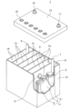
- FIG. 1 is a partially cutaway exploded perspective view showing the external appearance and internal structure of a lead-acid battery according to an embodiment of the present invention.
- a lead-acid battery includes an electrode plate group, an electrolytic solution, and a battery case.
- the electrode plate group includes a positive electrode, a negative electrode, and a separator.
- the electrolyte contains water and sulfuric acid.
- the positive electrode includes a positive current collector and a positive electrode material.
- the negative electrode includes a negative electrode current collector and a negative electrode material.
- the positive electrode material is held by the positive current collector, and the negative electrode material is held by the negative current collector.
- the positive electrode material includes lead dioxide.
- the negative electrode material contains lead.
- the electrode material in the positive electrode material and the negative electrode material is the part of the electrode plate (positive electrode or negative electrode) excluding the current collector.
- a member also referred to as a pasting member
- a mat or pasting paper may be attached to the electrode plate. Since the sticking member is used integrally with the electrode plate, it is included in the electrode plate. However, pasting members are not included in electrode materials.
- lead-acid batteries are not limited, it is assumed that they will be mainly used in PSOC.
- a lead-acid battery installed in a vehicle that is subjected to start-stop control is used in PSOC.
- Lead-acid batteries used in PSOC are often used in an undercharged state, so it is thought that water electrolysis is less likely to occur and stratification is likely to become a problem.
- An electrode plate group usually includes a plurality of positive electrodes, a plurality of negative electrodes, and a separator interposed between the positive electrode and the negative electrode.
- the positive electrodes and negative electrodes are alternately stacked with separators in between.
- the width direction of the electrode plate group (hereinafter referred to as the "x direction") is perpendicular to the stacking direction of the positive electrode, negative electrode, and separator (hereinafter referred to as the "y direction”), and the width direction (hereinafter referred to as the "y direction”) is vertical.
- the directions are perpendicular to each other.
- the vertical direction (vertical direction) is defined as the z direction. Each direction is based on the direction in which the lead-acid battery is placed in use.
- the battery case has a bottom, a side wall rising from the periphery of the bottom, and a lid that closes the open end of the side wall.
- the inside of the battery case may be divided into a plurality of spaces by partition walls.
- the inside of the battery case may be divided into a plurality of spaces (for example, six) by partition walls parallel to each other, for example.
- a plurality of partition walls may intersect with each other to divide the space into a plurality of (for example, four or more) spaces.
- the plurality of spaces (cell chambers) are formed such that, for example, a dimension X in the x direction (width direction of the electrode plate group) is larger than a dimension (group length) Y of the electrode plate group in the y direction (stacking direction).
- each parameter may be obtained for each of a plurality of cell chambers and an average value may be calculated.
- the x-direction dimension X and the z-direction dimension Z of the electrode plate group are regulated by the x-direction dimension (x) and the z-direction dimension (z) of the electrode plate.
- the dimension X of the electrode plate group may be regarded as the dimension (x) of the electrode plate.
- the dimension (x1) of the positive electrode in the x direction and the dimension (x2) of the negative electrode in the x direction are usually substantially the same. If (x1) and (x2) are different, the average value of (x1) and (x2) may be set as (x).
- the dimension Y in the y direction of the electrode plate group corresponds to the distance between the outermost parts in the stacking direction of two members (positive electrode, negative electrode, or separator) arranged on the outermost side in the stacking direction.
- the cross-sectional area Sg of the electrode plate group is represented by X ⁇ Y.
- a separator is placed on the outermost side in the stacking direction, a rib is provided on the surface of the separator facing the battery case, and the group length Y is If the distance is greater than the distance between the tips of opposing ribs, the distance between the tips of the ribs is set as the group length Y.
- the ratio Ra of the cross-sectional area (Se) of the electrolyte existing outside the outer edge of the electrode group to the cross-sectional area (Sg) of the electrode group is regulated to 0.20 or less. That is, the side wall or partition wall of the battery case is close to the electrode plate group, and the volume in which the electrolyte can stay is limited.
- the ratio Ra may be 0.15 or less, or may be 0.12 or less.
- the cross-sectional area (Sg) of the electrode plate group may be rephrased as the area of the orthogonal projection image of the electrode plate group with respect to the bottom of the battery case. If there is a space between the positive electrode or the negative electrode and the separator, the area of the orthogonal projection image of the space is also included in the area of the orthogonal projection image of the electrode plate group.
- the ratio Ra in a typical battery is 0.3, and the ratio Rb is 0.26.
- the cross section CS parallel to the bottom of the battery case of the lead acid battery is the cross section of the lead acid battery at a height of 2 cm from the bottom back surface (outer surface) of the battery case.
- the area (S) of the region surrounded by the inner edge of the battery case, the cross-sectional area of the electrode plate group (Sg), and the cross-sectional area of the electrolyte existing outside the outer edge of the electrode plate group (Se) is obtained by the following method.
- the area (S) is the cross-sectional area of a space (cell chamber) that accommodates one electrode plate group.
- the cross-sectional area of the electrolyte that exists outside the outer edge of the electrode plate group is It can be rephrased as “the area obtained by subtracting (the cross-sectional area of the electrode plate group) from (the cross-sectional area of the inside of the battery case housing the electrode plate group).” "The area of the region surrounded by the inner edge of the battery case” can be rephrased as “the cross-sectional area inside the battery case.””Cross-sectional area inside the battery case” can be rephrased as "cross-sectional area inside the cell chamber.”
- ⁇ Area (S)> Fill the space (cell chamber) that houses the electrode plates with water to a height of 1.5 cm from the back of the bottom of the battery case. Next, add water to a height of 2.5 cm. Calculate the area (S) from the added amount of water. If the amount of water added is 10 cm 3 , the cross-sectional area of the container is 10 cm 2 .
- ⁇ Cross-sectional area (Sg)> The thicknesses of the positive electrode plate, negative electrode plate, and separator each corresponding to a height of 2 cm from the bottom back surface of the battery case are measured using calipers.
- the thickness of the separator is the total thickness.
- the total thickness is the thickness including the ribs and a portion other than the ribs (base portion).
- the total thickness is the thickness of the base if the separator does not have ribs.
- the dimension (group length Y) of the electrode plate group in the y direction (stacking direction) is obtained from the following equation.
- Y thickness of positive electrode plate x number of positive electrode plates + thickness of negative electrode plate x number of negative electrode plates + number between electrode plates x thickness of separator (total thickness) + Number of separators in contact with the battery case or the ribs of the battery case x thickness of the base of the separator
- the distance between the tips of the ribs is taken as the group length Y.
- the dimension (x) of the electrode plate in the x direction is measured using a scale.
- the area S2 surrounded by the inner edge of the battery case in the cross section of the lead-acid battery at the intermediate depth of the liquid level of the battery case may be substantially the same. In that case, the flow of the electrolyte can be controlled throughout the upper and lower parts of the battery case, and the effect of improving the cycle durability of the lead acid battery used in the PSOC is enhanced.
- S1, S2, and S3 are substantially the same when 0.95 ⁇ S1/S2 ⁇ 1.05, 0.95 ⁇ S2/S3 ⁇ 1.05, and 0.95 ⁇ S3/S1 ⁇ This refers to the case where 1.05 is satisfied.
- the liquid level of the battery case refers to the ideal level of the liquid, and refers to the upper limit level stamped on the battery case.
- the area S is the product of its x-direction dimension Xs and y-direction dimension Ys ( Xs ⁇ Ys).
- the ratio Rb of the cross-sectional area of the positive electrode to the area (S) of the area surrounded by the inner edge of the battery case is 0.30 or more.
- the number of positive electrodes constituting the electrode plate group may be the same as the number of negative electrodes, or may be one more than the negative electrodes.
- the positive electrode may be disposed at one end in the stacking direction of the electrode plate group, and the negative electrode may be disposed at the other end.
- the positive electrodes may be arranged at both ends of the electrode plate group in the stacking direction.
- the positive electrode may be enclosed in a bag-shaped separator. Note that, generally, in order to ensure low-temperature high-rate performance, negative electrodes are often arranged at both ends of the electrode plate group in the stacking direction.
- the height of the separator ribs is the height of the separator in the y direction of the electrode plate group. Not included in dimensions.
- the height of the ribs regulates the size of the cross-sectional area Se of the electrolytic solution in the y direction. Since the ribs of the separator have a certain degree of flexibility, they may be deformed by being pushed by the side walls or partition walls. In that case, the height of the rib after deformation regulates the dimension of the cross-sectional area Se of the electrolyte in the y direction.
- the height of the rib is not included in the dimension in the y direction. If both the side wall or partition wall and the separator have ribs, and the ends of each rib are in contact with the side wall or partition wall, the height of the separator rib (if deformed, the height of the rib after deformation) The sum of the height of the ribs of the side walls or partition walls regulates the dimension of the cross-sectional area Se of the electrolytic solution in the y direction.
- the cycle durability of the lead acid battery used in PSOC can be significantly improved.
- the reason for this is thought to be that stratification due to sedimentation of the electrolytic solution that occurs during charging is suppressed, and as a result, the lifespan is no longer regulated by stratification. That is, to suppress stratification, the amount of electrolyte present around the lower part of the electrode plate group is reduced until Ra ⁇ 0.20 is satisfied, and the amount of sulfuric acid retained in the positive electrode is further reduced to 0.3 ⁇ Rb. It is effective to increase the amount until it is satisfied.
- the volume occupied by the positive electrode is made as large as possible in the space that can accommodate the electrolyte.
- the dimension X of the electrode plate group in the x direction is made as large as possible, and the dimension Xs of the cross-sectional area (S) of the cell chamber in the x direction is made as small as possible. Good too.
- the difference ⁇ x between the dimension Xs in the x direction of the region (cell chamber) surrounded by the inner edge of the battery case and the dimension X in the x direction of the electrode plate group is preferably, for example, 14 mm or less, and may be 12 mm or less.
- the distance from one end of the electrode plate group in the x direction to the inner edge of the battery case is preferably, for example, 7 mm or less, and may be 6 mm or less.
- ⁇ x/Xs is preferably 0.12 or less, may be 0.10 or less, or may be 0.08 or less.
- the gap ( ⁇ x) between the inner edge of the battery case and the electrode group in the width direction of the electrode plate group, and the distance (Xs) between the inner edges of the battery case in the width direction of the electrode plate group may be 0.12 or less, 0.10 or less, or 0.08 or less.
- the difference ⁇ y between the dimension Ys in the y direction of the area (cell chamber) surrounded by the inner edge of the battery case and the dimension Y in the y direction of the electrode plate group is preferably 2.5 mm or less, and even 2.0 mm or less. good.
- the distance from one end of the electrode plate group in the y direction to the inner edge of the battery case is preferably, for example, 1.25 mm or less, and may be 1.0 mm or less.
- ⁇ y/Ys is desirably 0.07 or less, may be 0.05 or less, or may be 0.04 or less.
- the gap ( ⁇ y) between the inner edge of the battery case and the electrode group in the thickness direction of the electrode plate group, and the distance between the inner edge of the battery case in the thickness direction of the electrode plate group (Ys ) may be 0.07 or less, 0.05 or less, or 0.04 or less.
- the cycle durability of the lead acid battery used in PSOC is further significantly improved.
- the content of antimony in the positive electrode material is preferably 0.01% by mass or more.
- the cycle durability of the lead-acid battery used in PSOC can be further significantly improved.
- the presence of the carbonaceous material in the negative electrode material improves the conductivity of the negative electrode material and suppresses sulfation of the negative electrode.
- Such an effect tends to be particularly large when Ra ⁇ 0.20 and 0.3 ⁇ Rb are satisfied.
- Significant suppression of sulfation promotes uniform reaction due to improved conductivity in the negative electrode material, improves the overall utilization of the negative and positive electrodes, and suppresses local deterioration of the electrode plate.
- Examples of carbonaceous materials included in the negative electrode material include carbon black, graphite, hard carbon, and soft carbon.
- carbon black include acetylene black, furnace black, and lamp black. Furnace black also includes Ketjen black (product name).
- Graphite may be any carbonaceous material including a graphite-type crystal structure, and may be either artificial graphite or natural graphite.
- the negative electrode material may contain one type of carbonaceous material, or may contain two or more types of carbonaceous materials.
- the content of the carbonaceous material in the negative electrode material is preferably 0.3% by mass or more.
- the content of the carbonaceous material in the negative electrode material may be 0.45% by mass or more, 1.0% by mass or more, or 1.2% by mass or more.
- the content of the carbonaceous material is, for example, 5% by mass or less, and may be 3% by mass or less.
- graphite may account for 70% or more by mass of the carbonaceous material, and may account for 100%.
- the lead-acid battery may be a liquid type battery (vented type battery) or a valve regulated lead-acid battery (VRLA).
- a liquid type battery Vented type battery
- VRLA valve regulated lead-acid battery
- the negative electrode includes a negative electrode material and a negative current collector.
- the negative electrode is obtained by coating or filling a negative electrode current collector with a negative electrode paste, aging and drying it to produce an unformed negative electrode, and then chemically converting the unformed negative electrode.
- the negative electrode paste is prepared, for example, by kneading lead powder, additives used as necessary, water, and sulfuric acid (or aqueous sulfuric acid solution).
- An unformed negative electrode may be aged at a temperature higher than room temperature and high humidity.
- Chemical formation can be performed by charging the electrode plate group containing an unformed negative electrode while immersing the electrode plate group in an electrolytic solution containing sulfuric acid in the battery case of the lead-acid battery. However, chemical formation may be performed before assembling the lead-acid battery or the electrode plate group. Spongy lead is formed by chemical formation.
- the negative electrode material includes a negative electrode active material (specifically, lead or lead sulfate) that develops capacity through an oxidation-reduction reaction, and additives used as necessary.
- a negative electrode active material specifically, lead or lead sulfate
- additives include organic anti-shrink agents, carbonaceous materials, barium sulfate, and reinforcing materials.
- Organic antishrink agents are known to have the effect of increasing the life performance of lead-acid batteries and improving the discharge performance at low temperatures.
- the organic anti-shrink agent include lignin, lignin derivatives, and synthetic organic anti-shrink agents (formaldehyde condensates of phenol compounds, etc.).
- lignin derivatives include lignin sulfonic acid or its salts (alkali metal salts, etc.).
- the negative electrode material may contain one kind or two or more kinds of organic antishrink agents.
- the content of the organic antishrink agent in the negative electrode material is, for example, 0.01% by mass or more, and may be 0.03% by mass or more.
- the content of the organic antishrink agent is, for example, 1.0% by mass or less, and may be 0.6% by mass or less.
- the content of barium sulfate in the negative electrode material may be 0.05% by mass or more and 3% by mass or less, or 0.1% by mass or more and 2% by mass or less.
- the negative electrode current collector may be formed by casting lead (Pb) or a lead alloy, or may be formed by processing a lead sheet or a lead alloy sheet. Examples of processing methods include expanding processing and punching processing. When a lattice-shaped current collector is used as the negative electrode current collector, it is easy to support the negative electrode material.
- the lead alloy used for the negative electrode current collector may be any of a Pb-Sb alloy, a Pb-Ca alloy, and a Pb-Ca-Sn alloy. These lead or lead alloys may further contain at least one element selected from the group consisting of Ba, Ag, Al, Bi, As, Se, Cu, etc. as an additive element.
- the negative electrode current collector may include a surface layer.
- the surface layer and the inside of the negative electrode current collector may have different compositions.
- the surface layer may be formed on a part of the negative electrode current collector.
- the surface layer may be formed on the edge of the negative electrode current collector.
- the surface layer of the ear portion may contain Sn or a Sn alloy.
- the lead-acid battery may be used immediately after chemical formation, or it may be possible that some time has elapsed since formation.
- it may be a lead-acid battery that is in use (preferably in the initial stage of use) after chemical conversion.
- a lead-acid battery in the early stage of use refers to a lead-acid battery that has not been used for a long time (for example, within two months from the start of use) and has hardly deteriorated.
- the fully charged state of a liquid lead-acid battery is defined by JIS D 5301:2019. More specifically, during charging, measurements were taken every 15 minutes at a current (A) that is 0.2 times the value stated as the rated capacity (value in Ah) in a water tank at 25°C ⁇ 2°C.
- a fully charged state is defined as a state in which a lead-acid battery is charged until the terminal voltage (V) or the electrolyte density converted to a temperature of 20° C. shows a constant value three times in a row with three significant figures.
- a fully charged state means a current of 0.2 times the value stated in the rated capacity (in Ah) in an air tank at 25°C ⁇ 2°C.
- A perform constant current and constant voltage charging at 2.23V/cell, and the charging current during constant voltage charging is 0.005 times the value stated in the rated capacity (value in Ah)
- A Charging has finished when the battery reaches .
- sample A a sample (hereinafter referred to as sample A) is obtained by separating the negative electrode material from the negative electrode. Sample A is pulverized as necessary and subjected to analysis.
- organic anti-shrink agent sample B Infrared spectra measured using organic anti-shrink agent sample B, UV-visible absorption spectrum measured using a UV-visible absorbance meter after diluting sample B with distilled water, etc. Dissolving sample B in a designated solvent such as heavy water.
- the type of organic anti-shrink agent is identified by combining the NMR spectrum of the solution obtained by this method, or information obtained from pyrolysis GC-MS, etc., which can obtain information on the individual compounds constituting the substance.
- the separation is performed as follows. First, the extract is measured by infrared spectroscopy, NMR and/or GC-MS to determine whether it contains multiple types of organic antishrink agents. Next, the molecular weight distribution of the extract is measured by GPC analysis, and if the plurality of organic anti-shrink agents can be separated by molecular weight, the organic anti-shrink agents are separated by column chromatography based on the difference in molecular weight. When separation is difficult due to differences in molecular weight, the organic anti-shrink agent is separated by a precipitation separation method, taking advantage of differences in solubility depending on the type and/or amount of functional groups that the organic anti-shrink agent has.
- one of the organic anti-shrink agents is coagulated by dropping an aqueous sulfuric acid solution into a mixture of the above extract dissolved in an aqueous NaOH solution and adjusting the pH of the mixture. ,To separate.
- the separated product is redissolved in an aqueous NaOH solution, and insoluble components are removed by filtration as described above.
- the remaining solution after separating one of the organic anti-shrink agents is concentrated.
- the resulting concentrate contains the other organic anti-shrink agent, and the insoluble components are removed from this concentrate by filtration as described above.
- the same organic preshrink agent is used for the calibration curve because the structural formula of the organic preshrink agent cannot be precisely specified.
- a calibration curve is created using an organic anti-shrink agent extracted from the negative electrode of the battery and a separately available organic polymer whose UV-visible absorption spectrum, infrared spectrum, and NMR spectrum have similar shapes. By doing so, the content of the organic shrink-proofing agent is measured using the ultraviolet-visible absorption spectrum.
- the dispersion liquid is subjected to suction filtration using a membrane filter whose mass has been measured in advance, and the membrane filter and the filtered sample are dried in a dryer at 110° C. ⁇ 5° C.
- the filtered sample is a mixed sample of carbonaceous material and barium sulfate.
- the mass (Mm) of sample C is measured by subtracting the mass of the membrane filter from the total mass of the mixed sample after drying (hereinafter referred to as sample C) and the membrane filter.
- sample C is placed in a crucible together with a membrane filter, and ignited at 1300° C. or higher.
- the remaining residue is barium oxide.
- the mass of barium sulfate (MB) is determined by converting the mass of barium oxide to the mass of barium sulfate.
- the mass of the carbonaceous material is calculated by subtracting the mass MB from the mass Mm.
- Positive electrodes can be classified into paste type, clad type, etc.
- the positive electrode of a lead-acid battery installed in a vehicle subject to idling stop control is generally a paste type positive electrode.
- the paste-type positive electrode includes a positive electrode material and a positive current collector.
- the positive electrode is obtained by applying or filling a positive electrode current collector with a positive electrode paste, aging and drying it to produce an unformed positive electrode, and then chemically converting the unformed positive electrode.
- the positive electrode paste is prepared, for example, by kneading lead powder, an optional additive (eg, antimony trioxide), water, and sulfuric acid (or an aqueous sulfuric acid solution).
- An unformed positive electrode plate may be aged at a temperature higher than room temperature and high humidity.
- Chemical formation can be performed by charging the electrode plate group containing an unformed positive electrode while immersing the electrode plate group in an electrolytic solution containing sulfuric acid in a battery case of a lead-acid battery. However, chemical formation may be performed before assembling the lead-acid battery or the electrode plate group.
- the positive electrode material contains a positive electrode active material (lead dioxide or lead sulfate) that develops capacity through a redox reaction, and may contain additives as necessary.
- a positive electrode active material lead dioxide or lead sulfate
- additives include antimony (Sb).
- Sb antimony
- the cycle durability of lead-acid batteries used in PSOC is further significantly improved.
- the content of antimony in the positive electrode material is desirably 0.01% by mass or more, and may be 0.03% by mass or more.
- the content of antimony in the positive electrode material may be, for example, less than 0.5% by mass, 0.4% by mass or less, or 0.1% by mass or less.
- the quantitative analysis method for antimony is shown below.
- the positive electrode is taken out from the lead-acid battery, the sulfuric acid is removed within 2 hours by washing with water, and the positive electrode is dried by blowing air at 60 ⁇ 5°C.
- an appropriate amount of a dry sample of the positive electrode material is taken from the positive electrode, and the mass of the sample is measured.
- the entire amount of the sample is dissolved in a mixed aqueous solution containing tartaric acid, nitric acid, and hydrogen peroxide.
- the solution obtained by dissolving the entire amount is diluted with ion-exchanged water as necessary to give a constant volume, and then the luminescence intensity of Sb in the solution is measured by ICP emission spectroscopy.
- the mass of Sb contained in the solution is determined using a calibration curve prepared in advance. The ratio of the Sb mass to the mass of the positive electrode active material sample subjected to analysis is determined as the Sb content.
- the positive electrode current collector of the paste-type positive electrode plate may be formed by casting lead (Pb) or a lead alloy, or may be formed by processing a lead sheet or a lead alloy sheet. Examples of processing methods include expanding processing and punching processing.
- a lattice-shaped current collector is used as the positive electrode current collector, it is easy to support the positive electrode material.
- the positive electrode current collector may include a surface layer. The surface layer of the positive electrode current collector and the inside thereof may have different compositions. The surface layer may be formed on a part of the positive electrode current collector. The surface layer may be formed only on the lattice portion, only on the ear portion, or only on the frame portion of the positive electrode current collector.
- the lead alloy used for the positive electrode current collector is preferably a Pb-Sb alloy, a Pb-Ca alloy, or a Pb-Ca-Sn alloy.
- the electrolytic solution is an aqueous solution containing sulfuric acid, and may be gelled if necessary.
- the electrolyte may contain the above polymer compound.
- the electrolytic solution may contain cations (for example, metal cations) and/or anions (for example, anions other than sulfate anions (phosphate ions, etc.)) as necessary.
- cations for example, metal cations
- anions for example, anions other than sulfate anions (phosphate ions, etc.
- the metal cation include at least one selected from the group consisting of Na ions, Li ions, Mg ions, and Al ions.
- separator As the separator disposed between the negative electrode and the positive electrode, for example, at least one selected from nonwoven fabric and microporous membrane is used.
- Nonwoven fabric is a mat made of fibers that are intertwined without being woven, and is mainly made of fibers. For example, 60% by mass or more of the nonwoven fabric is made of fibers.
- the fibers glass fibers, polymer fibers (polyolefin fibers, acrylic fibers, polyester fibers (polyethylene terephthalate fibers, etc.), etc.), pulp fibers, etc. can be used. Among them, glass fiber is preferred.
- the nonwoven fabric may contain acid-resistant inorganic powder, a polymer as a binder, and the like as components other than fibers.
- a microporous membrane is a porous sheet whose main component is other than fiber components.
- a composition containing a pore-forming agent is extruded into a sheet shape, and then the pore-forming agent is removed to form pores. can get.
- the microporous membrane is preferably made of an acid-resistant material, and preferably contains a polymer component as a main component.
- polymer component polyolefins (polyethylene, polypropylene, etc.) are preferred.
- Pore-forming agents include polymer powder, oil, and the like.
- the separator may be composed only of nonwoven fabric or only a microporous membrane.
- the separator may be a laminate of a nonwoven fabric and a microporous membrane, a laminate of different or the same types of materials bonded together, a laminate of interlocking irregularities formed on different or the same types of materials, or the like.
- the separator may be formed into a sheet shape or a bag shape.
- a sheet-like separator may be placed between the positive electrode and the negative electrode.
- the electrode plate may be sandwiched between folded sheet-like separators.
- a positive electrode sandwiched between folded sheet-shaped separators and a negative electrode sandwiched between folded sheet-shaped separators may be overlapped, or one of the positive electrode and negative electrode may be sandwiched between folded sheet-shaped separators and stacked with the other plate. It's okay.
- the bag-shaped separator may house a positive electrode or a negative electrode.
- the vertical direction of a lead-acid battery or the components of a lead-acid battery means the vertical direction of the lead-acid battery in the state in which the lead-acid battery is used.
- Each of the positive and negative electrode plates includes an ear for connection to an external terminal.
- the ears are usually located on the sides of the plates, although they may also be located on the sides of the plates, such as in horizontal valve-regulated lead-acid batteries. It is provided at the top so as to protrude upward.
- FIG. 1 shows the appearance of an example of a lead-acid battery according to an embodiment of the present invention.
- the lead-acid battery 1 includes a battery case 12 that houses an electrode plate group 11 and an electrolyte (not shown).
- the inside of the battery case 12 is partitioned into a plurality of cell chambers 14 by a partition wall 13.
- Each cell chamber 14 houses one electrode plate group 11.
- the opening of the battery case 12 is closed with a lid 15 having a positive terminal 16 and a negative terminal 17.
- the lid 15 is provided with a liquid port plug 18 for each cell chamber. When refilling water, the liquid port stopper 18 is removed and the rehydration liquid is replenished.
- the liquid port plug 18 may have a function of discharging gas generated within the cell chamber 14 to the outside of the battery.
- the electrode plate group 11 is constructed by alternately stacking a plurality of negative electrode plates 3 and a plurality of positive electrode plates 2 with separators 4 in between.
- the separator 4 is bag-shaped and packages the positive electrode plates 2 one by one.
- a positive electrode shelf 6 that connects the ears 2a of the plurality of positive electrode plates 2 in parallel is connected to the through-connection body 8, and the ears of the plurality of negative electrode plates 3 are connected in parallel.
- a negative electrode shelf 5 connecting the electrodes 3a in parallel is connected to the negative electrode column 7.
- the negative electrode column 7 is connected to a negative electrode terminal 17 outside the lid 15.
- the positive pole 9 is connected to the positive shelf 6
- the through connector 8 is connected to the negative shelf 5 .
- the positive electrode column 9 is connected to a positive electrode terminal 16 outside the lid 15.
- Each through-connection body 8 passes through a through-hole provided in the partition wall 13 and connects the electrode plate groups 11 of adjacent cell chambers 14 in series.
- the positive electrode shelf portion 6 is formed by welding the ears 2a provided at the top of each positive electrode plate 2 to each other using a cast-on strap method or a burning method.
- the negative electrode shelf 5 is also formed by welding the ears 3a provided at the top of each negative electrode plate 3 to each other.
- the lid 15 of the lead-acid battery illustrated in the example has a single-layer structure (single lid), but the structure is not limited to this.
- the lid 15 may have a double structure including an inner lid and an outer lid (or upper lid).
- the lid having a double structure may include a reflux structure between the inner lid and the outer lid for returning the electrolyte into the battery (inside the inner lid) from a reflux port provided in the inner lid.
- PSOC cycle durability is evaluated using the following procedure.
- Steps 1 to 4 shown in Table 1 below are performed in a water bath at 25° C. ⁇ 3° C. The number of cycles until the terminal voltage reaches 1.67 V/cell is used as an index of PSOC cycle durability.
- CC discharge means constant current discharge
- CV charge means constant voltage charge.
- 1CA is a current value (A) that is the same numerical value as the rated capacity (Ah) of the battery. For example, for a battery with a rated capacity of 30Ah, 1CA is 30A, and 1mCA is 30mA.
- the "adjustment discharge” is a discharge for adjusting the DOD (depth of discharge) before repeating the cycles of steps 2 and 3.
- the 20-hour rate current refers to a current that is 0.05 times (1/20) the current value (A) of the same numerical value as the rated capacity (Ah) of the battery.
- a lead-acid battery comprising a plate group, an electrolyte, and a battery case
- the electrode plate group includes a positive electrode, a negative electrode, and a separator
- the ratio Ra of the cross-sectional area of the electrolytic solution existing outside the outer edge of the electrode plate group to the cross-sectional area of the electrode plate group is 0.20 or less
- a lead-acid battery, wherein the ratio Rb of the cross-sectional area of the positive electrode to the area of the area surrounded by the inner edge of the battery case is 0.30 or more.
- a lead-acid battery comprising a plate group, an electrolyte, and a battery case
- the electrode plate group includes a positive electrode, a negative electrode, and a separator, In a cross section parallel to the bottom of the battery case of the lead acid battery, With respect to the cross-sectional area of the electrode plate group, The ratio Ra of the area excluding the cross-sectional area of the electrode plate group from the cross-sectional area inside the battery case housing the electrode plate group is 0.20 or less, A lead-acid battery, wherein the ratio Rb of the cross-sectional area of the positive electrode to the cross-sectional area inside the battery case is 0.30 or more.
- the positive electrode material contains antimony, The lead-acid battery according to (1) or (2) above, wherein the content of the antimony in the positive electrode material is 0.01% by mass or more.
- the negative electrode material includes a carbonaceous material, The lead-acid battery according to (1) to (3) above, wherein the content of the carbonaceous material in the negative electrode material is 0.3% by mass or more.
- the ratio of the gap ( ⁇ x) between the inner edge of the battery case and the electrode group in the width direction of the electrode plate group to the distance (x) between the inner edges of the battery case in the width direction of the electrode plate group is , 0.12 or less, The gap ( ⁇ y) between the inner edge of the battery case and the electrode group in the thickness direction of the electrode plate group, and the distance (y) between the inner edges of the battery case in the thickness direction of the electrode plate group.
- the lead-acid battery according to (9) above, wherein an area S3 surrounded by an inner edge of the battery case in a cross section of the lead-acid battery at an intermediate depth of the liquid level of the battery case is substantially the same.
- the negative electrode paste is filled into the mesh portion of an expanded grid made of a Pb--Ca--Sn alloy that is a negative electrode current collector, and is aged and dried to obtain an unformed negative electrode.
- test battery had a rated voltage of 12 V with six cells connected in series at a rated voltage of 2 V, and a rated 20 hour rate capacity of 59 Ah.
- the rated 20 hour rate capacity is the capacity when discharging from a fully charged state to 100% DOD (depth of discharge) at a 20 hour rate current.
- the electrode plate group of the test battery consisted of seven positive electrode plates and eight negative electrode plates, with the positive electrode plate housed in a bag-shaped separator.
- the bag-like separator is made of a microporous membrane made of polyethylene.
- the electrode plate group is housed in a polypropylene container together with an electrolyte (sulfuric acid aqueous solution).
- the battery case has six cell chambers. One electrode plate group is accommodated in each cell chamber.
- the ratio Ra of the cross-sectional area of the electrolyte existing outside the outer edge of the electrode plate group to the cross-sectional area of the electrode plate group was changed as shown in Table 2A, and ⁇ x, ⁇ y, ⁇ x/Xs, and ⁇ y/Ys were changed as shown in Table 2B.
- ⁇ x/Xs is preferably 0.12 or less, more preferably 0.08 or less, and ⁇ y/Ys is preferably 0.07 or less, further preferably 0.04 or less.
- Table 3 shows the correspondence between Examples 1 to 4 and batteries A1 to A4 and the correspondence between Comparative Examples 1 to 12 and batteries B1 to B12.
- Table 4B shows the correspondence between Examples 5 to 24 and batteries A5 to A24.
- Table 6 shows the correspondence between Comparative Examples 13 to 31 and batteries B13 to B31.
- cycle durability improves when Sb is included in the positive electrode material, but graphite is added to the negative electrode material at any Sb content. It can be seen that the cycle durability hardly changes even if it contains. This is thought to be because sulfation due to stratification is a dominant factor in limiting lifespan, so improving the conductivity of the negative electrode has little effect on cycle durability.
- the lead acid battery according to the present invention is suitable for use in an idling stop vehicle, for example, as an IS lead acid battery that is charged and discharged under PSOC conditions.
- lead-acid batteries can be suitably used, for example, as a starting power source for vehicles (such as automobiles and motorcycles), and as industrial power storage devices (for example, as a power source for electric vehicles (forklifts, etc.)). Note that these uses are merely examples, and the present invention is not limited to these uses.
- Electrode plate Group 12 Battery case 13: Partition wall 14: Cell chamber 15: Lid 16: Positive terminal 17: Negative terminal 18: Liquid port plug
Landscapes
- Chemical & Material Sciences (AREA)
- Chemical Kinetics & Catalysis (AREA)
- Electrochemistry (AREA)
- General Chemical & Material Sciences (AREA)
- Engineering & Computer Science (AREA)
- Manufacturing & Machinery (AREA)
- Secondary Cells (AREA)
Priority Applications (2)
| Application Number | Priority Date | Filing Date | Title |
|---|---|---|---|
| JP2024517338A JPWO2023210635A1 (https=) | 2022-04-26 | 2023-04-25 | |
| EP23796375.6A EP4485610A4 (en) | 2022-04-26 | 2023-04-25 | Lead storage battery |
Applications Claiming Priority (2)
| Application Number | Priority Date | Filing Date | Title |
|---|---|---|---|
| JP2022072543 | 2022-04-26 | ||
| JP2022-072543 | 2022-04-26 |
Publications (1)
| Publication Number | Publication Date |
|---|---|
| WO2023210635A1 true WO2023210635A1 (ja) | 2023-11-02 |
Family
ID=88518952
Family Applications (1)
| Application Number | Title | Priority Date | Filing Date |
|---|---|---|---|
| PCT/JP2023/016277 Ceased WO2023210635A1 (ja) | 2022-04-26 | 2023-04-25 | 鉛蓄電池 |
Country Status (3)
| Country | Link |
|---|---|
| EP (1) | EP4485610A4 (https=) |
| JP (1) | JPWO2023210635A1 (https=) |
| WO (1) | WO2023210635A1 (https=) |
Citations (7)
| Publication number | Priority date | Publication date | Assignee | Title |
|---|---|---|---|---|
| JPH04104476A (ja) | 1990-08-22 | 1992-04-06 | Yuasa Corp | 密閉形鉛蓄電池 |
| JPH06314572A (ja) | 1993-04-30 | 1994-11-08 | Yuasa Corp | 密閉形鉛蓄電池 |
| JPH11339843A (ja) * | 1998-05-26 | 1999-12-10 | Shin Kobe Electric Mach Co Ltd | 密閉形鉛蓄電池 |
| JP2005100726A (ja) | 2003-09-24 | 2005-04-14 | Shin Kobe Electric Mach Co Ltd | 液式鉛蓄電池 |
| JP2015103330A (ja) | 2013-11-22 | 2015-06-04 | 新神戸電機株式会社 | 鉛蓄電池 |
| WO2017099141A1 (ja) * | 2015-12-11 | 2017-06-15 | 日立化成株式会社 | 鉛蓄電池 |
| WO2020105484A1 (ja) * | 2018-11-20 | 2020-05-28 | 株式会社Gsユアサ | 鉛蓄電池 |
Family Cites Families (2)
| Publication number | Priority date | Publication date | Assignee | Title |
|---|---|---|---|---|
| WO2020080421A1 (ja) * | 2018-10-16 | 2020-04-23 | 株式会社Gsユアサ | 鉛蓄電池 |
| JP7248034B2 (ja) * | 2018-10-16 | 2023-03-29 | 株式会社Gsユアサ | 鉛蓄電池、および、鉛蓄電池の製造方法 |
-
2023
- 2023-04-25 WO PCT/JP2023/016277 patent/WO2023210635A1/ja not_active Ceased
- 2023-04-25 JP JP2024517338A patent/JPWO2023210635A1/ja active Pending
- 2023-04-25 EP EP23796375.6A patent/EP4485610A4/en active Pending
Patent Citations (7)
| Publication number | Priority date | Publication date | Assignee | Title |
|---|---|---|---|---|
| JPH04104476A (ja) | 1990-08-22 | 1992-04-06 | Yuasa Corp | 密閉形鉛蓄電池 |
| JPH06314572A (ja) | 1993-04-30 | 1994-11-08 | Yuasa Corp | 密閉形鉛蓄電池 |
| JPH11339843A (ja) * | 1998-05-26 | 1999-12-10 | Shin Kobe Electric Mach Co Ltd | 密閉形鉛蓄電池 |
| JP2005100726A (ja) | 2003-09-24 | 2005-04-14 | Shin Kobe Electric Mach Co Ltd | 液式鉛蓄電池 |
| JP2015103330A (ja) | 2013-11-22 | 2015-06-04 | 新神戸電機株式会社 | 鉛蓄電池 |
| WO2017099141A1 (ja) * | 2015-12-11 | 2017-06-15 | 日立化成株式会社 | 鉛蓄電池 |
| WO2020105484A1 (ja) * | 2018-11-20 | 2020-05-28 | 株式会社Gsユアサ | 鉛蓄電池 |
Non-Patent Citations (1)
| Title |
|---|
| See also references of EP4485610A4 |
Also Published As
| Publication number | Publication date |
|---|---|
| JPWO2023210635A1 (https=) | 2023-11-02 |
| EP4485610A1 (en) | 2025-01-01 |
| EP4485610A4 (en) | 2025-09-03 |
Similar Documents
| Publication | Publication Date | Title |
|---|---|---|
| JP7255492B2 (ja) | 鉛蓄電池 | |
| JP7355005B2 (ja) | 鉛蓄電池 | |
| WO2023210513A1 (ja) | 鉛蓄電池およびその製造方法、および使用方法 | |
| JP7424310B2 (ja) | 鉛蓄電池 | |
| JP7124828B2 (ja) | 鉛蓄電池 | |
| JP7375457B2 (ja) | 鉛蓄電池 | |
| JP6756182B2 (ja) | 鉛蓄電池 | |
| CN111279540A (zh) | 铅蓄电池 | |
| JP6766504B2 (ja) | 鉛蓄電池 | |
| JP6954353B2 (ja) | 鉛蓄電池 | |
| WO2019087683A1 (ja) | 鉛蓄電池 | |
| JP7147776B2 (ja) | 鉛蓄電池 | |
| WO2023210635A1 (ja) | 鉛蓄電池 | |
| JP7099450B2 (ja) | 鉛蓄電池 | |
| JP2024104758A (ja) | 鉛蓄電池 | |
| WO2019087682A1 (ja) | 鉛蓄電池 | |
| JP7622635B2 (ja) | 鉛蓄電池 | |
| WO2019087680A1 (ja) | 鉛蓄電池 | |
| JP7797970B2 (ja) | 鉛蓄電池 | |
| JP6750376B2 (ja) | 鉛蓄電池 | |
| WO2024005041A1 (ja) | 鉛蓄電池 | |
| WO2019225161A1 (ja) | 鉛蓄電池 | |
| JP7694585B2 (ja) | 鉛蓄電池用クラッド式正極板および鉛蓄電池 | |
| JP7459669B2 (ja) | 鉛蓄電池 | |
| JP2024029809A (ja) | 鉛蓄電池 |
Legal Events
| Date | Code | Title | Description |
|---|---|---|---|
| 121 | Ep: the epo has been informed by wipo that ep was designated in this application |
Ref document number: 23796375 Country of ref document: EP Kind code of ref document: A1 |
|
| WWE | Wipo information: entry into national phase |
Ref document number: 2023796375 Country of ref document: EP |
|
| ENP | Entry into the national phase |
Ref document number: 2023796375 Country of ref document: EP Effective date: 20240927 |
|
| WWE | Wipo information: entry into national phase |
Ref document number: 2024517338 Country of ref document: JP |
|
| WWE | Wipo information: entry into national phase |
Ref document number: 2401007057 Country of ref document: TH |
|
| NENP | Non-entry into the national phase |
Ref country code: DE |