WO2023209846A1 - 入出力装置、およびステアリング測定装置 - Google Patents
入出力装置、およびステアリング測定装置 Download PDFInfo
- Publication number
- WO2023209846A1 WO2023209846A1 PCT/JP2022/019028 JP2022019028W WO2023209846A1 WO 2023209846 A1 WO2023209846 A1 WO 2023209846A1 JP 2022019028 W JP2022019028 W JP 2022019028W WO 2023209846 A1 WO2023209846 A1 WO 2023209846A1
- Authority
- WO
- WIPO (PCT)
- Prior art keywords
- steering
- waveform
- recommended
- input
- response data
- Prior art date
- Legal status (The legal status is an assumption and is not a legal conclusion. Google has not performed a legal analysis and makes no representation as to the accuracy of the status listed.)
- Ceased
Links
Images




Classifications
-
- G—PHYSICS
- G01—MEASURING; TESTING
- G01M—TESTING STATIC OR DYNAMIC BALANCE OF MACHINES OR STRUCTURES; TESTING OF STRUCTURES OR APPARATUS, NOT OTHERWISE PROVIDED FOR
- G01M17/00—Testing of vehicles
- G01M17/007—Wheeled or endless-tracked vehicles
- G01M17/06—Steering behaviour; Rolling behaviour
-
- B—PERFORMING OPERATIONS; TRANSPORTING
- B62—LAND VEHICLES FOR TRAVELLING OTHERWISE THAN ON RAILS
- B62D—MOTOR VEHICLES; TRAILERS
- B62D5/00—Power-assisted or power-driven steering
- B62D5/04—Power-assisted or power-driven steering electrical, e.g. using an electric servo-motor connected to, or forming part of, the steering gear
- B62D5/0457—Power-assisted or power-driven steering electrical, e.g. using an electric servo-motor connected to, or forming part of, the steering gear characterised by control features of the drive means as such
Definitions
- the present disclosure relates to an input/output device and a steering measurement device.
- Patent Document 1 discloses a testing device for an electric power steering device.
- This test device includes an input/output device and a control device.
- the input/output device identifies steering characteristics.
- the control device controls a rotating machine included in the electric power steering device.
- the input/output device sends an excitation instruction to the control device, the control device causes the rotating machine to vibrate, and a response to the excitation is detected by a rotation detector, a torque detector, and a microphone.
- the above response is transmitted to the input/output device, and the input/output device identifies the mechanical characteristics, frequency characteristics, and noise characteristics of the steering based on the vibration instruction and the response.
- a steering test is one of the tests for electric power steering devices.
- a human or a robot operates (steering) a steering wheel based on a predetermined steering waveform (time change in angle or angular velocity).
- a steering waveform time change in angle or angular velocity
- By conducting a steering test it is possible to evaluate the electric power steering device in an environment close to actual usage conditions.
- steering conditions there are various conditions such as different angles or angular velocities for moving the steering wheel.
- evaluation items in the steering test such as evaluation of frequency characteristics (transfer function gain and stability margin, etc.), evaluation of steering feel, and evaluation of vibration and noise.
- the presence or absence of problems in each evaluation item may differ. Therefore, it is required to conduct a steering test under steering conditions that take into consideration the items to be evaluated.
- the present disclosure has been made to solve the above-mentioned problems, and aims to provide an input/output device and a steering measurement device that can perform a steering test under appropriate steering conditions.
- An input/output device is connected to a control device that controls a rotating machine of an electric power steering device, and detects during steering based on a target steering waveform that is a target value of a steering waveform that indicates a change in steering over time.
- a communication receiving unit that receives response data of the electric power steering device from the control device; a recommended steering waveform generation unit that generates a recommended steering waveform recommended as the target steering waveform based on the response data; and an output section that outputs a recommended steering waveform.
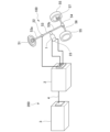
- FIG. 1 is a diagram showing an input/output device and an electric power steering device according to Embodiment 1.
- FIG. 1 is a block diagram showing a control device according to Embodiment 1.
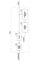
- FIG. 1 is a block diagram showing an input/output device according to Embodiment 1.
- FIG. 3 is a block diagram showing a recommended steering waveform generation unit according to the first embodiment.
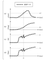
- FIG. 3 is a diagram showing an example of response data according to Embodiment 1.
- FIG. FIG. 2 is a block diagram showing a generation unit according to Embodiment 1.
- FIG. FIG. 3 is a diagram showing an example of a recommended steering waveform according to the first embodiment.
- FIG. 2 is a block diagram showing an input/output device according to a second embodiment.
- FIG. 7 is a diagram illustrating an example of a steering waveform displayed by a display unit according to Embodiment 2.
- FIG. 7 is a diagram illustrating an example of an instantaneous value of a steering waveform displayed by a display unit according to Embodiment 2.
- FIG. 3 is a diagram showing an example of response data including vibration.
- FIG. 3 is a block diagram showing a generation unit according to Embodiment 3.
- FIG. 7 is a diagram showing an example of a recommended steering waveform according to Embodiment 3, which does not include turn-back steering.
- FIG. 7 is a diagram showing an example of a recommended steering waveform according to Embodiment 3, including a turning steering waveform.
- FIG. 1 is a diagram showing an input/output device 3 and an electric power steering device 100 according to the first embodiment.
- the electric power steering device 100 according to the present embodiment includes a steering wheel 51, a steering shaft 53, a rack and pinion gear 54, a pair of wheels 55, a tie rod 56, and a rotating machine 1. , a control device 2, a torque detector 22, and a rotation detector 23.
- Electric power steering device 100 is mounted on a vehicle.
- the input/output device 3 is connected to the control device 2 via the communication network 4 when generating a recommended steering waveform (details will be described later). Note that in this specification, the input/output device 3 and the control device 2 may be collectively referred to as the "steering measurement device 200.”
- CAN Controller Area Network
- FlexRay registered trademark
- Ethernet registered trademark
- cables for the communication network 4 may be wired within the vehicle.
- Steering torque is applied to the steering wheel 51 by a driver (not shown) operating a steering wheel (not shown) or the like.
- the steering shaft 53 has an input shaft 53a connected to the steering wheel 51, and an output shaft 53b connected to the rack and pinion gear 54.
- the input shaft 53a and the output shaft 53b are connected to each other by a torsion bar (not shown).
- the torsion bar is arranged inside the torque detector 22 and passes through the torque detector 22 in the axial direction. Note that in this specification, the steering wheel 51, steering shaft 53, and torsion bar may be collectively referred to as a "steering".
- Steering torque applied to the steering wheel 51 is transmitted to a rack (not shown) in the rack and pinion gear 54 via the torsion bar in the torque detector 22, the steering shaft 53, and the rack and pinion gear 54. .
- the rack and wheels 55 are connected via tie rods 56 and knuckle arms 57. Therefore, when steering torque from steering wheel operation is transmitted to the rack, the tie rod 56 pushes the knuckle arm 57 on one wheel 55, and the tie rod 56 pulls the knuckle arm 57 on the other wheel 55. As a result, a steering angle is given to the wheels 55, and the wheels 55 are steered.
- a voltage is applied to the rotating machine 1 by the control device 2.
- the rotating machine 1 generates torque according to the applied voltage.
- Torque (output torque) generated from the rotating machine 1 is transmitted to the steering shaft 53.
- the output torque of the rotating machine 1 functions as a steering assist force and reduces the steering torque that the driver should apply during steering.
- the rotating machine 1 may include, for example, an AC motor such as a permanent magnet synchronous motor or an induction motor, or a DC motor.
- the torque detector 22 detects the steering torque applied to the steering wheel 51 by the driver. More specifically, when a steering torque is applied, the torsion bar twists approximately in proportion to the steering torque. Torque detector 22 detects the direction and angle of twist of the torsion bar. The torque detector 22 converts the detected torsion angle into a steering torque signal and outputs it to the control device 2 (power feeding section 24 and communication transmitting section 25).
- the rotation detector 23 is attached to the rotating shaft of the rotating machine 1.
- the rotation detector 23 detects the angular velocity of the rotating shaft.
- the rotation detector 23 converts the detected angular velocity into an angular velocity signal, and outputs the signal to the control device 2 (power feeding unit 24 and communication transmitting unit 25).
- FIG. 2 is a block diagram showing the internal configuration of the control device 2 according to this embodiment.
- the control device 2 includes a current detector 21, a power feeding section 24, and a communication transmitting section 25.
- the current detector 21 detects the current flowing through the rotating machine 1 when the power supply unit 24 applies a voltage to the rotating machine 1.
- Current detector 21 converts the detected current into a current signal and outputs it to power supply section 24 and communication transmission section 25 .
- the power supply unit 24 generates a voltage to be applied to the rotating machine 1 based on the steering torque signal output by the torque detector 22 and the angular velocity signal output by the rotation detector 23. More specifically, the power supply unit 24 according to the present embodiment determines a current command corresponding to the output torque output by the rotating machine 1 based on the steering torque signal and the angular velocity signal. In order to cause the rotating machine 1 to generate this output torque, the power supply unit 24 generates a voltage command for controlling the current flowing through the rotating machine 1 based on the current command and the current signal output by the current detector 21. . Based on the voltage command, the rotating machine 1 applies a voltage to the rotating machine 1 using a drive circuit (not shown) to cause current to flow therein.
- the communication transmitting unit 25 transmits the steering torque signal outputted by the torque detector 22, the angular velocity signal outputted by the rotation detector 23, and the current signal outputted by the current detector 21 to the input/output device 3 (communication receiving unit 31).
- the steering torque signal, the angular velocity signal, and the current signal may be collectively referred to as “response data of the electric power steering device 100" or simply “response data.”
- FIG. 3 is a block diagram showing the internal configuration of the input/output device 3 according to this embodiment.
- the input/output device 3 includes a communication receiving section 31, a recommended steering waveform generating section 32, an output section 33, and a display section 34.
- a communication terminal such as a tablet computer or a notebook personal computer may be used.
- the input/output device 3 performs various processes including generation of a recommended steering waveform based on the response data received by the communication receiving section 31.
- the communication receiving section 31 receives the response data transmitted by the communication transmitting section 25.
- the communication receiving section 31 outputs the received response data to the recommended steering waveform generating section 32.
- a waveform indicating a change in steering over time in a steering test of the electric power steering device 100 is referred to as a "steering waveform W.”
- the steering waveform W is a waveform that shows a change in the angle of the steering wheel 51 over time.
- the steering waveform W may be a waveform indicating a change in the angular velocity of the steering wheel 51 over time.
- the steering waveform W may be a waveform that shows a change in the angle of the rotating machine 1 over time.
- the steering waveform W may be a waveform indicating a change in the angular velocity of the rotating machine 1 over time.
- target steering waveform Wtar is a waveform that indicates a temporal change in the angle or angular velocity that the examiner should give to the steering wheel 51 in the steering test.
- target steering waveform Wtar is a waveform that indicates a temporal change in the angle or angular velocity that should be caused in the rotating machine 1 in the steering test.
- steering waveform W recommended as the target steering waveform Wtar in the steering test is referred to as a "recommended steering waveform Wrec.”
- the recommended steering waveform generating section 32 generates a recommended steering waveform Wrec based on the response data output by the communication receiving section 31.
- the recommended steering waveform generation section 32 outputs the generated recommended steering waveform Wrec to the output section 33.
- the output unit 33 outputs the recommended steering waveform Wrec to the display unit 34 as output data.
- the display unit 34 displays the output data output by the output unit 33.
- the output unit 33 does not output output data to the display unit 34.
- the output unit 33 may be configured to output the recommended steering waveform Wrec as text data or a CSV file.
- the configuration (output format) of the output unit 33 can be changed as appropriate as long as the user can confirm the output data or use the output data as a command value for steering the robot that steers the steering wheel.
- the recommended steering waveform generation section 32 includes a storage/reproduction section 321, an operating point extraction section 322, and a generation section 323.
- the storage/reproduction unit 321 stores response data and reproduces the stored response data.
- the operating point extraction unit 322 extracts a quantity representing the characteristics of steering (steering waveform W) from the response data as an operating point, and converts the operating point into a numerical value.
- the generation unit 323 generates the recommended steering waveform Wrec using the operating point.
- the storage/reproduction unit 321 Since the recommended steering waveform generation section 32 includes the storage/reproduction section 321, the recommended steering waveform Wrec generated from the stored response data can be repeatedly generated in subsequent steering tests. Thereby, the reproducibility of the steering test can be improved.
- the user may arbitrarily specify which time period of the response data is to be stored and reproduced, or may be specified using an automatic determination device.
- the automatic determiner automatically determines the time period to be stored/reproduced based on, for example, the magnitude of the response data value or the presence or absence of vibration. Note that as long as the recommended steering waveform generation section 32 can repeatedly generate the recommended steering waveform Wrec, the configuration of the storage/reproduction section 321 can be changed as appropriate.
- the storage/reproduction unit 321 may be configured to store and reproduce the operating point, or may be configured to store and reproduce the recommended steering waveform Wrec.
- FIG. 5 is a diagram showing an example of response data according to this embodiment.
- the response data includes the angular velocity ⁇ (angular velocity signal) of the rotating machine, the detected current I (current signal), and the steering torque T (steering torque signal).
- the angle ⁇ obtained by integrating the angular velocity ⁇ can also be considered as one type of response data.
- the angle ⁇ may be obtained via the communication network 4 without differentiating the value detected by the rotation detector 23.
- only one of the angular velocity ⁇ , the angle ⁇ , the detected current I, and the steering torque T may be used, or a plurality of them may be used in combination.
- the operating point extraction unit 322 extracts operating points (operating point angular velocity ⁇ 1, operating point angle ⁇ 1, operating point detection current I1, operating point steering torque T1) from each of the angular velocity ⁇ , angle ⁇ , detected current I, and steering torque T. Extract.
- the operating point angular velocity ⁇ 1 has various definitions, such as the maximum value of the angular velocity ⁇ , the average value of the angular velocity ⁇ , the maximum value of the angular velocity ⁇ after low-pass processing, or the value of the angular velocity ⁇ at a time that satisfies a certain condition. It is possible.
- various definitions are possible for the operating point angle ⁇ 1, the operating point detection current I1, and the operating point steering torque T1.
- the operating point angular velocity ⁇ 1, the operating point angle ⁇ 1, the operating point detection current I1, and the operating point steering torque T1 are defined as the maximum value of the angular velocity ⁇ , the maximum value of the angle ⁇ , and the maximum value of the detection current I, respectively. , and the maximum value of the steering torque T.
- the operating point extracting unit 322 outputs the extracted operating point to the generating unit 323 (multiplying unit 325).
- FIG. 6 is a block diagram showing the generation unit 323 according to this embodiment.
- the generation unit 323 according to this embodiment includes a reference function generation unit 324, a multiplication unit 325, and a physical quantity conversion unit 326.
- the reference function generation unit 324 generates a reference function.
- the reference function generation section 324 outputs the generated reference function to the multiplication section 325.
- the multiplier 325 multiplies the reference function output by the reference function generator 324 and the operating point output by the operating point extractor 322.
- the multiplication unit 325 outputs the multiplication result to the physical quantity conversion unit 326.
- the physical quantity converter 326 converts the output of the multiplier 325 to generate a recommended steering waveform Wrec.
- the reference function generated by the reference function generation unit 324 may be freely defined as long as the maximum value is approximately 1.
- a sine wave, a swept sine wave (sine sweep), a rectangular wave, a single pulse wave, a spline curve, or the like can be used as the reference function.
- a sine wave as the reference function will be introduced.
- FIG. 7 is a diagram showing the recommended steering waveform Wrec according to the present embodiment.
- the recommended steering waveform Wrec may include only one of the angle ⁇ and the angular velocity ⁇ of the rotating machine 1, or may include both.
- Graph (a) shown in FIG. 7 is the recommended steering waveform Wrec of the angle ⁇ .
- This recommended steering waveform Wrec can reproduce steering including the operating point angle ⁇ 1.
- This recommended steering waveform Wrec can be expressed by the following equation (1).
- F indicates the steering angle frequency.
- the steering angle frequency F can be set freely, and may be, for example, about 0.2 ⁇ to 10 ⁇ .
- the steering angular frequency F is a fixed value, but the steering angular frequency F may be varied if a swept sine wave is used as the reference function.
- the graph (b) shown in FIG. 7 is the recommended steering waveform Wrec of the angular velocity ⁇ .
- This recommended steering waveform Wrec can reproduce steering including the operating point angular velocity ⁇ 1.
- This recommended steering waveform Wrec can be expressed by the following equation (2).
- the physical quantity conversion unit 326 receives the value output by the multiplication unit 325 as input, and converts the input value so that the recommended steering waveform Wrec becomes a desired physical quantity.
- the physical quantity conversion unit 326 outputs the converted value to the output unit 33. Note that if the input operating point and the physical quantity of the recommended steering waveform Wrec match, the above conversion process is not necessary. If the input operating point and the physical quantity of the recommended steering waveform Wrec do not match, the physical quantity conversion unit 326 performs the above conversion process.
- the physical quantity conversion unit 326 performs differentiation or integration. By doing so, the other physical quantity is also determined.
- an offset value that is an integral constant is required. In this embodiment, by setting the above initial conditions, the offset value can be uniquely determined. Note that depending on the operating point and reference function, the waveform obtained by differentiating the recommended steering waveform Wrec at an angle ⁇ that includes the operating point angle ⁇ 1 may not necessarily include the operating point angular velocity ⁇ 1. The waveform obtained by integrating the recommended steering waveform Wrec including the angular velocity ⁇ does not necessarily include the operating point angle ⁇ 1. Therefore, caution is required.
- the recommended steering waveform generation unit 32 may be configured to output the recommended steering waveform Wrec of the steering angle (the angle of the steering wheel 51) or the recommended steering waveform Wrec of the steering angular velocity (the angular velocity of the steering wheel 51).
- the physical quantity conversion unit 326 can generate the recommended steering waveform Wrec using the steering angle or the steering angular velocity as a physical quantity by performing a process of dividing the angle ⁇ or the angular velocity ⁇ by the gear ratio Gn.
- the angle ⁇ and the angular velocity ⁇ are not included in the response data. Even in such a case, the recommended steering waveform Wrec of the angle ⁇ and the angular velocity ⁇ can be approximately generated by using the detected current I and the steering torque T as response data, for example.
- the operating point extraction section 322 extracts the operating point detection current I1 and the operating point steering torque T1, so the output value of the multiplication section 325 is based on these operating point I1. , T1.
- Equation (3) Kt is the motor output coefficient, and Kalign is the reaction force spring coefficient. Further, the relationship between the detected current I and the steering torque T can be roughly determined from the model of the controller included in the electric power steering device 100. Therefore, even if the response data includes only one of the detected current I and the steering torque T, the angle ⁇ can be approximately determined. Note that in order to express the angle ⁇ more accurately, the angle ⁇ may be calculated using an equation of motion that reflects the viscosity term, inertia term, and friction term. Alternatively, a map may be defined that outputs the angle ⁇ by inputting the detected current I or the steering torque T, and the angle ⁇ may be calculated using the map.
- the physical quantity conversion unit 326 performing the above calculation, it is possible to output the recommended steering waveform Wrec of the angle ⁇ . Further, by differentiating the recommended steering waveform Wrec of the angle ⁇ obtained by the above calculations by the physical quantity conversion unit 326, the recommended steering waveform Wrec of the angular velocity ⁇ can also be output.
- the conversion process by the physical quantity conversion unit 326 was performed on the recommended steering waveform Wrec, but a configuration in which the physical quantity conversion unit 326 performs conversion on response data and operating points is adopted. Good too.
- the functions of the units 31 to 34 included in the input/output device 3 shown in FIG. 3 may be realized by a CPU (Central Processing Unit) executing a program.
- LSI Large Scale Integration
- ASIC Application Specific Integrated Circuit
- FPGA Field-Programmable Gate Array
- GPU GPU
- Each unit 31 to 31 uses hardware (including circuitry) such as It is also possible to realize 34 functions.
- the input/output device 3 is connected to the control device 2 that controls the rotating machine 1 of the electric power steering device 100, and is connected to the target value of the steering waveform W indicating a change in steering over time.
- a communication receiving unit 31 receives from the control device 2 response data of the electric power steering device 100 detected during steering based on a target steering waveform Wtar, and a recommendation recommended as the target steering waveform Wtar based on the response data. It includes a recommended steering waveform generating section 32 that generates the steering waveform Wrec, and an output section 33 that outputs the recommended steering waveform Wrec.
- the recommended steering waveform Wrec to be given during the steering test is output. Therefore, even a user with little knowledge of steering methods can conduct a steering test under appropriate steering conditions by steering while referring to the recommended steering waveform Wrec.
- a steering test can be performed under appropriate steering conditions based on existing response data.
- the electric power steering device 100 should include only the current detector 21, torque detector 22, and rotation detector 23, the configuration of this embodiment can be realized at relatively low cost.
- the response data includes at least one of the steering torque T of the steering included in the electric power steering device 100, the detected current I of the rotating machine 1, the angle ⁇ of the rotating machine 1, and the angular velocity ⁇ of the rotating machine 1.
- the recommended steering waveform Wrec can be output by using at least one of the steering torque T, the detected current I, the angle ⁇ , and the angular velocity ⁇ .
- the recommended steering waveform generation unit 32 generates the recommended steering waveform Wrec so as to include operating points extracted from the response data and indicating characteristics of steering. With this configuration, it becomes easier to unify the operating points of the steering tests performed multiple times, and it becomes easier to ensure the reproducibility of the steering tests.
- the steering measuring device 200 includes the above-described input/output device 3 and a control device 2, and the control device 2 is configured to measure the detected electric power steering device 100 when the steering wheel is steered.
- the response is sent to the input/output device 3 as response data.
- Embodiment 2 Next, a second embodiment will be described, but the basic configuration is the same as that of the first embodiment. Therefore, a description of similar configurations will be omitted, and only the different points will be described.
- This embodiment differs from Embodiment 1 in that the output unit 33 outputs both the recommended steering waveform Wrec and the actual steering waveform Wact obtained from the response data.
- FIG. 8 is a block diagram showing the input/output device 3A according to this embodiment.
- the input/output device 3A according to this embodiment includes an actual steering waveform calculation section 35.
- the communication receiving section 31 outputs the response data received from the communication transmitting section 25 to the recommended steering waveform generating section 32 (multiplying section 325) and the actual steering waveform calculating section 35.
- the actual steering waveform calculating section 35 generates an actual steering waveform Wact based on the response data output by the communication receiving section 31.
- the actual steering waveform calculation unit 35 outputs the generated actual steering waveform Wact to the output unit 33.
- the output unit 33 outputs both the recommended steering waveform Wrec outputted by the recommended steering waveform generation unit 32 (physical quantity conversion unit 326) and the actual steering waveform Wact outputted by the actual steering waveform calculation unit 35 as output data. It is output to the display section 34.
- the "actual steering waveform Wact” means a steering waveform W that shows a change over time in actual steering performed during a steering test. More specifically, the actual steering waveform Wact includes an actual temporal change in the angle of the steering wheel 51 during steering, an actual temporal change in the angular velocity of the steering wheel 51 during steering, and an actual temporal change in the angle ⁇ of the rotating machine 1 during steering. It is a waveform showing a time change of , or an actual time change of the angular velocity ⁇ of the rotating machine 1 during steering.
- the specific configuration of the actual steering waveform calculation section 35 may be the same as the configuration of the physical quantity conversion section 326 described in the embodiment.
- the conversion process by the actual steering waveform calculating section 35 is not necessary. If the physical quantities of the response data and the actual steering waveform Wact do not match, the actual steering waveform calculating section 35 performs the same conversion process as the physical quantity converting section 326.
- FIG. 9 is a diagram showing a display example of the steering waveform W on the display unit 34 according to the present embodiment.
- the recommended steering waveform Wrec and the actual steering waveform Wact are displayed in a superimposed manner on the time series graph.
- the display format of the recommended steering waveform Wrec and the actual steering waveform Wact on the display unit 34 is not limited to the above-mentioned time series graph.
- the format of the display on the display unit 34 may be a bar graph, a polar coordinate graph, or a graphic format such as a diagram of a rotating handle.
- FIG. 10 is a diagram showing a display example of the instantaneous value of the steering waveform W on the display unit 34 according to the present embodiment.
- the instantaneous value Wrecins of the recommended steering waveform Wrec and the instantaneous value Wactins of the actual steering waveform Wact are displayed superimposed on the bar graph.
- the maximum value Wrecmax of the recommended steering waveform Wrec is displayed.
- the configuration in which the display unit 34 displays a representative value such as the maximum value or the minimum value of the recommended steering waveform Wrec is suitable in that the steering by the user and the recommended steering waveform Wrec become closer to each other.
- the display unit 34 may display the recommended steering waveform Wrec and the actual steering waveform Wact in a numerical format instead of a graphic format.
- the display unit 34 may display the recommended steering waveform Wrec and the actual steering waveform Wact in both a graphical format and a numerical format.
- the output unit 33 outputs both the recommended steering waveform Wrec and the actual steering waveform Wact, which is the actual steering waveform W.
- the user can easily recognize the difference between the actual steering waveform Wact and the recommended steering waveform Wrec. Therefore, the steering by the user and the recommended steering waveform Wrec become closer to each other. That is, the reproducibility of the steering test can be improved.
- the input/output device 3A further includes a display section 34 that displays output data output from the output section 33 in a numerical format or a graphic format.
- Embodiment 3 Next, Embodiment 3 will be described, but the basic configuration is the same as Embodiment 1 and Embodiment 2. Therefore, a description of similar configurations will be omitted, and only the different points will be described.
- Embodiments 1 and 2 differs from Embodiments 1 and 2 in the method of generating the recommended steering waveform Wrec when the response data includes vibration. More specifically, the input/output device 3B according to the present embodiment generates the recommended steering waveform Wrec so as to reproduce the vibration included in the response data and to facilitate identification of the cause of the vibration. Note that the block diagram of the input/output device 3B is omitted because it is similar to the block diagram of the input/output devices 3 and 3A according to the embodiment.
- FIG. 11 is a diagram showing an example of response data including vibration.
- vibrations occur in the detected current I and the steering torque T around time t1. If the generation of vibration is unacceptable, it is necessary to eliminate the vibration.
- the causes of vibrations are generally identified and countermeasures are taken in accordance with the causes of vibrations.
- the input/output device 3B according to the present embodiment generates the recommended steering waveform Wrec so as to reproduce the vibration included in the response data and to facilitate identification of the cause of the vibration.
- the recommended steering waveform Wrec for reproducing the vibration included in the response data will be explained.
- the amplitude of vibration is maximum at time t1. Therefore, the operating point extraction unit 322 according to the present embodiment extracts the response data at time t1 as the operating point angle ⁇ 1, the operating point angular velocity ⁇ 1, the operating point detection current I1, and the operating point steering torque T1.
- the recommended steering waveform generation unit 32 generates the recommended steering waveform Wrec including the response data at time t1.
- there is a high probability that the above-mentioned vibration will be reproduced in the response data.
- the method of extracting the operating point is not limited to the above example, that is, the method of extracting the response data at the time when the vibration amplitude is maximum as the operating point.
- the operating points may be extracted after removing vibration components by applying a low-pass filter, a band-pass filter, etc. to the response data. According to this method, the operating point can be extracted even when the raw value of the response data changes drastically due to the occurrence of vibration.
- the response data at the center time of the section where the vibration occurs may be used as the operating point.
- the recommended steering waveform generation unit 32 generates a recommended steering waveform Wrec that is easy to perform using both of these two methods.
- the vibration frequency f varies depending on the vibration factor.
- Typical causes of vibration, in descending order of vibration frequency f are road reaction force due to uneven road surfaces, instability due to insufficient phase margin in the control system, and instability due to insufficient gain margin in the control system. , and sensor noise.
- by examining the frequency f of the vibration in question it becomes easier to identify the cause of the vibration.
- Short-time Fourier transform is a process that extracts the amplitude of a signal at each time and each frequency component. Specifically, first, frame data is created by trimming the vibration waveform with a time width tW. A large number of such frame data are prepared at different times. Each frame data is subjected to FFT (fast Fourier transform) processing with a window function.
- FFT fast Fourier transform
- the time at which the amplitude of vibration is maximum among all times and all frequency components can be extracted as the vibration occurrence time t1.
- the vibration occurrence time t1 can be used to define the operating point.
- the amplitude (maximum amplitude) at the vibration occurrence time t1 can be evaluated as the vibration generation level.
- the frequency component at which the vibration amplitude is maximum at each time point near the vibration occurrence time t1 it is possible to extract the frequency f of the vibration at each time point.
- tW is the time width of short-time Fourier transform, that is, the time width of each frame data.
- the amplitude output by short-time Fourier transform is calculated based on frame data trimmed with time width tW. Therefore, if the duration of the vibration to be analyzed is less than the time width tW, the amplitude of the vibration will not be calculated correctly, and the calculated value of the amplitude will be smaller than the actual amplitude value. This adversely affects the extraction of the vibration amplitude, vibration occurrence time t1, and frequency f. Therefore, it is desirable that the duration of the vibration to be analyzed be equal to or longer than the time width tW.
- the recommended steering waveform generation unit 32 generates a recommended steering waveform Wrec in which a state near the operating point (that is, response data when vibration occurs) continues for a time width tW or more. This makes it possible to improve the accuracy of analysis of the vibration amplitude and frequency f.
- vibration factors there are two types of vibration factors: those that cause vibrations that have rotational synchronization correlation, and those that cause vibrations that do not have rotational synchronization correlation.
- vibration factors that cause vibrations with rotational synchronization correlation include structural asymmetry, dead time errors, and the like. More specifically, structural asymmetry refers to structural asymmetry related to components such as the rotating machine 1, the angle sensor of the rotating machine 1, the inverter that drives the rotating machine 1, and gears. Dead time error is an error that occurs during switching of the inverter.
- vibration factors that cause vibrations that have no rotation synchronization correlation include instability of the control system, road reaction force due to unevenness of the road surface, and sensor noise.
- ⁇ is the angular velocity fluctuation amount
- ⁇ ( ⁇ 1) is the determination safety factor.
- the determination safety factor ⁇ is a value set to prevent erroneous determination when determining rotation synchronization correlation.
- the recommended steering waveform generation unit 32 generates a recommended steering waveform Wrec that includes the operating point angular velocity ⁇ 1 at the time of vibration occurrence and that can ensure the above-mentioned angular velocity fluctuation amount ⁇ . More specifically, the recommended steering waveform Wrec is generated so as to include a high angular velocity ⁇ H and a low angular velocity ⁇ L defined by the following equations (7) and (8).
- FIG. 12 is a block diagram showing the generation unit 323B according to this embodiment.
- the generation unit 323B according to this embodiment includes an angular velocity variation ratio calculation unit 327.
- the operating point extraction section 322 outputs the extracted operating point to the multiplication section 325 and the angular velocity variation ratio calculation section 327.
- the angular velocity variation ratio calculation unit 327 outputs the calculated high angular velocity ratio ⁇ Hr and low angular velocity ratio ⁇ Lr to the reference function generation unit 324.
- the reference function generation unit 324 transforms the reference function to include the high angular velocity ratio ⁇ Hr and the low angular velocity ratio ⁇ Lr.
- the reference function generation unit 324 outputs the modified reference function to the multiplication unit 325.
- the recommended steering waveform generation unit 32 can generate the recommended steering waveform Wrec that includes both the high angular velocity ⁇ H and the low angular velocity ⁇ L. In other words, the angular velocity fluctuation amount ⁇ can be ensured, and the recommended steering waveform Wrec that can determine whether there is a rotation synchronization correlation can be generated.
- FIG. 13 is a diagram showing an example of the recommended steering waveform Wrec according to the present embodiment, which does not include turn-back steering.
- the recommended steering waveform Wrec shown in FIG. 13 includes a high angular velocity ⁇ H and a low angular velocity ⁇ L near the operating point angular velocity ⁇ 1. Further, the angular velocity duration period of the high angular velocity ⁇ H or more continues for a time width tW or more, and the angular velocity duration period of the low angular velocity ⁇ L or less continues for a time width tW or more.
- the recommended steering waveform Wrec includes the operating point angular velocity ⁇ 1. Further, since the angular velocity near the operating point angular velocity ⁇ 1 continues for the time width tW or longer, the frequency f can be analyzed with high precision by using short-time Fourier transform. Furthermore, since the recommended steering waveform Wrec includes the angular velocity fluctuation amount ⁇ , it is possible to determine the rotation synchronization correlation.
- FIG. 14 is a diagram showing an example of the recommended steering waveform Wrec according to the present embodiment, which includes turn-back steering.
- the angular velocity durations of the high angular velocity ⁇ H and the low angular velocity ⁇ L near the operating point angular velocity ⁇ 1 each continue for a time width tW or longer.
- the recommended steering waveform Wrec shown in FIG. 14 includes a constant period in which the angular velocity ⁇ is a high angular velocity ⁇ H and a low angular velocity ⁇ L. Therefore, compared to, for example, the recommended steering waveform Wrec shown in FIG. 13, steering and analysis become easier. Further, since the recommended steering waveform Wrec includes switching steering, the maximum displacement amount of the angle ⁇ is smaller than the recommended steering waveform Wrec not including switching steering. Thereby, even when the operating point angular velocity ⁇ 1 is large, it is possible to reduce the possibility that the rotation angle of the steering wheel exceeds the range of motion.
- the rotation synchronization correlation can also be determined using a period in the recommended steering waveform Wrec in which the angular velocity ⁇ is negative (for example, a period in which it is ⁇ H).
- a period in which it is ⁇ H since the rotation directions are different, there is a possibility that vibrations that are the object of analysis (reproduction and analysis) will not occur. Therefore, it is desirable to generate the recommended steering waveform Wrec so that the high angular velocity ⁇ H and the low angular velocity ⁇ L have the same sign.
- the angular velocity variation ratio calculation unit 327 is used to transform the reference function based on the operating point angular velocity ⁇ 1, but the configuration of the generation unit 323B is not limited to this. If it is possible to define in advance the waveform shape of the reference function that can sufficiently ensure ⁇ without depending on the operating point angular velocity ⁇ 1, the generation unit 323B does not need to have the angular velocity variation ratio calculation unit 327. In this case, the configuration of the generation unit 323B according to this embodiment may be the same as the configuration of the generation unit 323 in the first and second embodiments.
- the recommended steering waveform generation unit 32 generates a response at the time when the vibration occurs when response data including vibration to be analyzed is input.
- a recommended steering waveform Wrec including data values is generated. According to this configuration, it is possible to generate a recommended steering waveform Wrec that easily reproduces the vibration to be analyzed. Therefore, the efficiency of vibration verification can be improved.
- the recommended steering waveform generation unit 32 when response data including a vibration to be analyzed is input, the recommended steering waveform generation unit 32 generates a signal in order to analyze the frequency f and amplitude of the vibration from the response data at the time when the vibration occurs. A recommended steering waveform Wrec that continues for a time longer than the required length is generated. This configuration makes it easier to analyze the frequency f and amplitude of vibration using a technique such as short-time Fourier transform. This makes it easier to identify the cause of vibration.
- the recommended steering waveform generation unit 32 when response data including vibration to be analyzed is input, the recommended steering waveform generation unit 32 generates necessary signals to determine whether there is a correlation between the frequency f of the vibration and the angular velocity ⁇ of the rotating machine 1. A recommended steering waveform Wrec including the angular velocity fluctuation amount ⁇ is generated. This configuration makes it easier to examine the correlation between the vibration frequency f and the angular velocity ⁇ . This makes it easier to identify the cause of vibration.
- each of the components of the input/output devices 3, 3A, and 3B and the steering measurement device 200 described above has a computer system therein. Then, a program for realizing the functions of each component of the input/output devices 3, 3A, 3B and the steering measuring device 200 described above is recorded on a computer-readable recording medium, and the program recorded on this recording medium is read. By loading and executing the information into a computer system, the processing in each of the components of the input/output devices 3, 3A, 3B and the steering measuring device 200 described above may be performed.
- “reading a program recorded on a recording medium into a computer system and executing it” includes installing the program on the computer system.
- the "computer system” herein includes an OS and hardware such as peripheral devices.
- a "computer system” may include a plurality of computer devices connected via the Internet or a network including a communication line such as a WAN, LAN, or a dedicated line.
- a communication line such as a WAN, LAN, or a dedicated line.
- computer-readable recording medium refers to portable media such as flexible disks, magneto-optical disks, ROMs, and CD-ROMs, and storage devices such as hard disks built into computer systems.
- the recording medium storing the program may be a non-transitory recording medium such as a CD-ROM.
Landscapes
- Physics & Mathematics (AREA)
- General Physics & Mathematics (AREA)
- Steering Control In Accordance With Driving Conditions (AREA)
Priority Applications (4)
| Application Number | Priority Date | Filing Date | Title |
|---|---|---|---|
| CN202280095021.9A CN119032261A (zh) | 2022-04-27 | 2022-04-27 | 输入输出装置以及转向测定装置 |
| PCT/JP2022/019028 WO2023209846A1 (ja) | 2022-04-27 | 2022-04-27 | 入出力装置、およびステアリング測定装置 |
| EP22940126.0A EP4516636A4 (en) | 2022-04-27 | 2022-04-27 | Input/output device and steering measurement device |
| JP2024517683A JP7710611B2 (ja) | 2022-04-27 | 2022-04-27 | 入出力装置、およびステアリング測定装置 |
Applications Claiming Priority (1)
| Application Number | Priority Date | Filing Date | Title |
|---|---|---|---|
| PCT/JP2022/019028 WO2023209846A1 (ja) | 2022-04-27 | 2022-04-27 | 入出力装置、およびステアリング測定装置 |
Publications (1)
| Publication Number | Publication Date |
|---|---|
| WO2023209846A1 true WO2023209846A1 (ja) | 2023-11-02 |
Family
ID=88518266
Family Applications (1)
| Application Number | Title | Priority Date | Filing Date |
|---|---|---|---|
| PCT/JP2022/019028 Ceased WO2023209846A1 (ja) | 2022-04-27 | 2022-04-27 | 入出力装置、およびステアリング測定装置 |
Country Status (4)
| Country | Link |
|---|---|
| EP (1) | EP4516636A4 (https=) |
| JP (1) | JP7710611B2 (https=) |
| CN (1) | CN119032261A (https=) |
| WO (1) | WO2023209846A1 (https=) |
Citations (6)
| Publication number | Priority date | Publication date | Assignee | Title |
|---|---|---|---|---|
| JP2006145517A (ja) * | 2004-10-21 | 2006-06-08 | Toyota Motor Corp | 操舵特性の評価方法 |
| JP2007237848A (ja) * | 2006-03-07 | 2007-09-20 | Mitsubishi Electric Corp | 車両用操舵制御装置 |
| WO2008053816A1 (fr) * | 2006-10-30 | 2008-05-08 | Nsk Ltd. | Procédé de réglage d'un appareil de direction à assistance électrique |
| JP6129409B2 (ja) | 2014-04-10 | 2017-05-17 | 三菱電機株式会社 | 入出力装置、ステアリング測定装置、および、制御装置 |
| WO2019074087A1 (ja) * | 2017-10-13 | 2019-04-18 | 日本精工株式会社 | 電動パワーステアリング装置 |
| JP2021165062A (ja) * | 2020-04-06 | 2021-10-14 | 株式会社Subaru | 自動操舵制御装置 |
Family Cites Families (3)
| Publication number | Priority date | Publication date | Assignee | Title |
|---|---|---|---|---|
| JP3663332B2 (ja) * | 2000-03-15 | 2005-06-22 | 光洋精工株式会社 | 電動パワーステアリング制御装置 |
| JP4831425B2 (ja) * | 2007-03-19 | 2011-12-07 | 株式会社ジェイテクト | ステアリング装置の試験装置 |
| CN116380455B (zh) * | 2018-09-28 | 2026-03-24 | 国际计测器株式会社 | 测试装置和驱动操纵装置的方法 |
-
2022
- 2022-04-27 EP EP22940126.0A patent/EP4516636A4/en active Pending
- 2022-04-27 JP JP2024517683A patent/JP7710611B2/ja active Active
- 2022-04-27 WO PCT/JP2022/019028 patent/WO2023209846A1/ja not_active Ceased
- 2022-04-27 CN CN202280095021.9A patent/CN119032261A/zh active Pending
Patent Citations (6)
| Publication number | Priority date | Publication date | Assignee | Title |
|---|---|---|---|---|
| JP2006145517A (ja) * | 2004-10-21 | 2006-06-08 | Toyota Motor Corp | 操舵特性の評価方法 |
| JP2007237848A (ja) * | 2006-03-07 | 2007-09-20 | Mitsubishi Electric Corp | 車両用操舵制御装置 |
| WO2008053816A1 (fr) * | 2006-10-30 | 2008-05-08 | Nsk Ltd. | Procédé de réglage d'un appareil de direction à assistance électrique |
| JP6129409B2 (ja) | 2014-04-10 | 2017-05-17 | 三菱電機株式会社 | 入出力装置、ステアリング測定装置、および、制御装置 |
| WO2019074087A1 (ja) * | 2017-10-13 | 2019-04-18 | 日本精工株式会社 | 電動パワーステアリング装置 |
| JP2021165062A (ja) * | 2020-04-06 | 2021-10-14 | 株式会社Subaru | 自動操舵制御装置 |
Non-Patent Citations (1)
| Title |
|---|
| See also references of EP4516636A4 |
Also Published As
| Publication number | Publication date |
|---|---|
| EP4516636A1 (en) | 2025-03-05 |
| CN119032261A (zh) | 2024-11-26 |
| JP7710611B2 (ja) | 2025-07-18 |
| JPWO2023209846A1 (https=) | 2023-11-02 |
| EP4516636A4 (en) | 2025-06-25 |
Similar Documents
| Publication | Publication Date | Title |
|---|---|---|
| CN110320038B (zh) | 滚动轴承的异常诊断方法以及异常诊断装置 | |
| JP6129409B2 (ja) | 入出力装置、ステアリング測定装置、および、制御装置 | |
| WO2001082462A1 (en) | Motor controller | |
| JP6511573B1 (ja) | 転がり軸受の異常診断方法及び異常診断装置、異常診断プログラム | |
| CN104713712B (zh) | 一种基于匹配解调变换的转子碰摩故障检测方法及系统 | |
| JP2021508059A (ja) | 試験構造のための動的な試験経過を実行する試験台及び方法 | |
| CN110907864A (zh) | 电机定子绕组的故障检测方法、装置、设备及存储介质 | |
| US20250269896A1 (en) | Input/output device and steering measurement device | |
| WO2023209846A1 (ja) | 入出力装置、およびステアリング測定装置 | |
| JP4788543B2 (ja) | エンジンベンチシステムのパラメータ推定装置 | |
| CN114207402B (zh) | 联轴器的特性评价装置和特性评价方法 | |
| JPH11352020A (ja) | ダンパー組立体の動的捩り特性の計測装置及びダンパー組立体の動的捩り特性の計測方法 | |
| JP4045860B2 (ja) | 動力伝達系の試験装置とその制御方法 | |
| JP7710610B2 (ja) | 入出力装置及びステアリング測定装置 | |
| JP2002098617A (ja) | エンジンベンチシステムのエンジントルク推定方法 | |
| JP4844472B2 (ja) | 電気慣性制御応答の評価方法 | |
| JP2010112900A (ja) | シャシーダイナモメータの拘束装置と車両剛性の特性同定方法 | |
| US20250377251A1 (en) | In-line harmonic removal processing with discounted averaging | |
| JP5414662B2 (ja) | ダイナモメータの特性マップ作成方法及びダイナモメータ | |
| US20260126347A1 (en) | Response time evaluation method | |
| JPH07260564A (ja) | 回転機器の異常診断装置及び方法 | |
| JP3055788B2 (ja) | 振動特性解析方法及び装置 | |
| JP3949635B2 (ja) | 回転体の回転振動測定方法および装置 | |
| JP3891998B2 (ja) | 電動機の回転数検出方法及び装置 | |
| JPH06117917A (ja) | 機械振動系振動応答特性計測方法およびその計測方法を用いた計測装置 |
Legal Events
| Date | Code | Title | Description |
|---|---|---|---|
| 121 | Ep: the epo has been informed by wipo that ep was designated in this application |
Ref document number: 22940126 Country of ref document: EP Kind code of ref document: A1 |
|
| ENP | Entry into the national phase |
Ref document number: 2024517683 Country of ref document: JP Kind code of ref document: A |
|
| WWE | Wipo information: entry into national phase |
Ref document number: 202280095021.9 Country of ref document: CN Ref document number: 202427078810 Country of ref document: IN |
|
| WWE | Wipo information: entry into national phase |
Ref document number: 2022940126 Country of ref document: EP |
|
| NENP | Non-entry into the national phase |
Ref country code: DE |
|
| ENP | Entry into the national phase |
Ref document number: 2022940126 Country of ref document: EP Effective date: 20241127 |