WO2023203640A1 - Échangeur de chaleur et climatiseur - Google Patents
Échangeur de chaleur et climatiseur Download PDFInfo
- Publication number
- WO2023203640A1 WO2023203640A1 PCT/JP2022/018182 JP2022018182W WO2023203640A1 WO 2023203640 A1 WO2023203640 A1 WO 2023203640A1 JP 2022018182 W JP2022018182 W JP 2022018182W WO 2023203640 A1 WO2023203640 A1 WO 2023203640A1
- Authority
- WO
- WIPO (PCT)
- Prior art keywords
- heat transfer
- fin
- transfer promoting
- drainage space
- heat exchanger
- Prior art date
Links
- 238000011144 upstream manufacturing Methods 0.000 claims abstract description 37
- 230000001737 promoting effect Effects 0.000 claims description 116
- 239000003507 refrigerant Substances 0.000 description 61
- XLYOFNOQVPJJNP-UHFFFAOYSA-N water Substances O XLYOFNOQVPJJNP-UHFFFAOYSA-N 0.000 description 41
- 239000000463 material Substances 0.000 description 12
- 230000007423 decrease Effects 0.000 description 11
- 238000005219 brazing Methods 0.000 description 7
- 238000001816 cooling Methods 0.000 description 6
- 238000010586 diagram Methods 0.000 description 6
- 238000010438 heat treatment Methods 0.000 description 6
- 239000007788 liquid Substances 0.000 description 5
- 238000012986 modification Methods 0.000 description 5
- 230000004048 modification Effects 0.000 description 5
- 239000012530 fluid Substances 0.000 description 3
- 238000007710 freezing Methods 0.000 description 3
- 230000008014 freezing Effects 0.000 description 3
- 238000004378 air conditioning Methods 0.000 description 2
- 229910052782 aluminium Inorganic materials 0.000 description 2
- XAGFODPZIPBFFR-UHFFFAOYSA-N aluminium Chemical compound [Al] XAGFODPZIPBFFR-UHFFFAOYSA-N 0.000 description 2
- 238000005520 cutting process Methods 0.000 description 2
- 230000000717 retained effect Effects 0.000 description 2
- 229910000838 Al alloy Inorganic materials 0.000 description 1
- 238000009825 accumulation Methods 0.000 description 1
- CSDREXVUYHZDNP-UHFFFAOYSA-N alumanylidynesilicon Chemical compound [Al].[Si] CSDREXVUYHZDNP-UHFFFAOYSA-N 0.000 description 1
- 230000015572 biosynthetic process Effects 0.000 description 1
- 230000000903 blocking effect Effects 0.000 description 1
- 238000005253 cladding Methods 0.000 description 1
- 239000000470 constituent Substances 0.000 description 1
- 230000006866 deterioration Effects 0.000 description 1
- 238000002474 experimental method Methods 0.000 description 1
- 239000000945 filler Substances 0.000 description 1
- 238000003780 insertion Methods 0.000 description 1
- 230000037431 insertion Effects 0.000 description 1
- 230000014759 maintenance of location Effects 0.000 description 1
- 238000004519 manufacturing process Methods 0.000 description 1
- 229910052751 metal Inorganic materials 0.000 description 1
- 239000002184 metal Substances 0.000 description 1
- 239000000203 mixture Substances 0.000 description 1
- 239000002244 precipitate Substances 0.000 description 1
- 238000005057 refrigeration Methods 0.000 description 1
Images


Classifications
-
- B—PERFORMING OPERATIONS; TRANSPORTING
- B60—VEHICLES IN GENERAL
- B60H—ARRANGEMENTS OF HEATING, COOLING, VENTILATING OR OTHER AIR-TREATING DEVICES SPECIALLY ADAPTED FOR PASSENGER OR GOODS SPACES OF VEHICLES
- B60H1/00—Heating, cooling or ventilating [HVAC] devices
- B60H1/32—Cooling devices
-
- F—MECHANICAL ENGINEERING; LIGHTING; HEATING; WEAPONS; BLASTING
- F24—HEATING; RANGES; VENTILATING
- F24F—AIR-CONDITIONING; AIR-HUMIDIFICATION; VENTILATION; USE OF AIR CURRENTS FOR SCREENING
- F24F1/00—Room units for air-conditioning, e.g. separate or self-contained units or units receiving primary air from a central station
- F24F1/0007—Indoor units, e.g. fan coil units
- F24F1/0059—Indoor units, e.g. fan coil units characterised by heat exchangers
- F24F1/0067—Indoor units, e.g. fan coil units characterised by heat exchangers by the shape of the heat exchangers or of parts thereof, e.g. of their fins
-
- F—MECHANICAL ENGINEERING; LIGHTING; HEATING; WEAPONS; BLASTING
- F28—HEAT EXCHANGE IN GENERAL
- F28F—DETAILS OF HEAT-EXCHANGE AND HEAT-TRANSFER APPARATUS, OF GENERAL APPLICATION
- F28F1/00—Tubular elements; Assemblies of tubular elements
- F28F1/10—Tubular elements and assemblies thereof with means for increasing heat-transfer area, e.g. with fins, with projections, with recesses
- F28F1/12—Tubular elements and assemblies thereof with means for increasing heat-transfer area, e.g. with fins, with projections, with recesses the means being only outside the tubular element
- F28F1/24—Tubular elements and assemblies thereof with means for increasing heat-transfer area, e.g. with fins, with projections, with recesses the means being only outside the tubular element and extending transversely
- F28F1/30—Tubular elements and assemblies thereof with means for increasing heat-transfer area, e.g. with fins, with projections, with recesses the means being only outside the tubular element and extending transversely the means being attachable to the element
-
- F—MECHANICAL ENGINEERING; LIGHTING; HEATING; WEAPONS; BLASTING
- F28—HEAT EXCHANGE IN GENERAL
- F28F—DETAILS OF HEAT-EXCHANGE AND HEAT-TRANSFER APPARATUS, OF GENERAL APPLICATION
- F28F1/00—Tubular elements; Assemblies of tubular elements
- F28F1/10—Tubular elements and assemblies thereof with means for increasing heat-transfer area, e.g. with fins, with projections, with recesses
- F28F1/12—Tubular elements and assemblies thereof with means for increasing heat-transfer area, e.g. with fins, with projections, with recesses the means being only outside the tubular element
- F28F1/24—Tubular elements and assemblies thereof with means for increasing heat-transfer area, e.g. with fins, with projections, with recesses the means being only outside the tubular element and extending transversely
- F28F1/32—Tubular elements and assemblies thereof with means for increasing heat-transfer area, e.g. with fins, with projections, with recesses the means being only outside the tubular element and extending transversely the means having portions engaging further tubular elements
Definitions
- the present disclosure relates to a heat exchanger and an air conditioner.
- a corrugated fin tube type heat exchanger in which corrugated fins are arranged between a plurality of flat heat exchanger tubes connected between a pair of headers through which refrigerant passes is popular.
- conventional heat exchangers have a structure that discharges water that is deposited on the surface of the corrugated fins.
- it is necessary to have a large opening area, which reduces the heat transfer area of the corrugated fins and causes a reduction in heat transfer performance.
- the present disclosure has been made in view of the above circumstances, and provides a heat exchanger and an air conditioner that can suppress a decrease in heat transfer performance by reducing the decrease in heat transfer area while improving drainage performance.
- the purpose is to provide equipment.
- the heat exchanger according to the present disclosure includes a plurality of heat exchanger tubes arranged in parallel at intervals in a direction intersecting an air flow direction, a fin portion that is a flat surface, and one of the plurality of adjacent heat exchanger tubes.
- one or more heat transfer promoting section groups having a plurality of heat transfer promoting sections extending from one side toward the other and arranged obliquely with respect to the fin section, and arranged between the plurality of heat transfer tubes.
- the plurality of heat transfer promoting parts include a first heat transfer promoting part disposed on the most upstream side in the flow direction of the air, and the first heat transfer promoting part and the A first drainage space is provided between the first heat transfer promoting part and the fin part on the upstream side in the air flow direction closest to the first heat transfer promoting part, and a second drainage space is provided between the adjacent heat transfer promoting parts.
- the area of the first drainage space when viewed perpendicularly to the fin portion is larger than the area of the second drainage space.
- the area of the first drainage space is larger than the area of the second drainage space when viewed perpendicularly to the fin portion. Therefore, by relatively increasing the area of the first drainage space between the upstream fin section and the heat transfer promoting section, the amount of drainage from the first drainage space increases, and the heat exchanger of the present disclosure , can suppress the accumulation of condensed water and improve drainage performance. Moreover, since the area of the second drainage space between adjacent heat transfer promoting parts is relatively small, the decrease in the heat transfer area of the corrugated fins can be reduced, and the decrease in heat transfer performance can be suppressed.
- FIG. 1 is a diagram showing the configuration of a heat exchanger according to Embodiment 1.
- FIG. 1 is a schematic perspective view of a flat heat exchanger tube and corrugated fins according to Embodiment 1.
- FIG. 2 is a schematic diagram of the fin portion of the corrugated fin according to the first embodiment when viewed from above.
- FIG. 2 is a schematic vertical cross-sectional view of a fin portion of a corrugated fin according to Embodiment 1.
- FIG. It is a schematic diagram when the fin part of the corrugated fin which has the 1st drainage space and the 3rd drainage space of the modification based on Embodiment 1 is viewed from above.
- FIG. 3 is a schematic top view of a corrugated fin according to a second embodiment.
- FIG. 1 is a schematic perspective view of a flat heat exchanger tube and corrugated fins according to Embodiment 1.
- FIG. 2 is a schematic diagram of the fin portion of the corrugated fin according to the first embodiment
- FIG. 7 is a side sectional view of a fin portion of a corrugated fin according to a third embodiment.
- FIG. 7 is a side cross-sectional view of a fin portion of a corrugated fin according to a fourth embodiment.
- FIG. 7 is a schematic top view of a fin portion of a corrugated fin according to a fourth embodiment.
- FIG. 7 is a side cross-sectional view of a fin portion of a corrugated fin according to a modification of Embodiment 4;
- FIG. 7 is a schematic top view of a fin portion of a corrugated fin according to a modification of Embodiment 4;
- FIG. 7 is a side cross-sectional view of a fin portion of a corrugated fin according to a fifth embodiment. It is a figure showing the composition of the air conditioner concerning Embodiment 6.
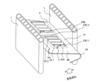
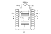
- FIG. 1 is a diagram showing the configuration of a heat exchanger 10 according to the first embodiment.
- the heat exchanger 10 of Embodiment 1 is a corrugated fin tube type heat exchanger 10 that is a parallel piping type.
- the heat exchanger 10 includes a plurality of flat heat exchanger tubes 1, a plurality of corrugated fins 2, a lower header 3A, and an upper header 3B.
- the vertical direction of the paper surface in FIG. 1 will be defined as the height direction of the heat exchanger 10.
- the left-right direction of the paper surface in FIG. 1 is assumed to be the horizontal direction.
- the front-rear direction in FIG. 1 is defined as the depth direction of the heat exchanger 10.
- the lower header 3A is a pipe that is pipe-connected to other devices constituting the air conditioner, into which refrigerant, which is a fluid serving as a heat exchange medium, flows in and out, and which branches or merges the refrigerant.
- the upper header 3B is a pipe that is pipe-connected to other devices constituting the air conditioner, through which refrigerant, which is a fluid serving as a heat exchange medium, flows in and out, and branches or merges the refrigerant.
- a plurality of flat heat exchanger tubes 1 are arranged in parallel between the lower header 3A and the upper header 3B so as to be perpendicular to the lower header 3A and the upper header 3B.
- the lower header 3A and the upper header 3B are vertically arranged vertically. Liquid refrigerant passes through the lower header 3A.
- a gaseous refrigerant passes through the upper header 3B.
- Each flat heat exchanger tube 1 is arranged at equal intervals in the horizontal direction with a space between adjacent flat heat exchanger tubes 1.
- the flat heat exchanger tubes 1 are inserted into insertion holes (not shown) of the lower header 3A and the upper header 3B, and are brazed and joined.
- the brazing material for brazing for example, a brazing material containing aluminum is used.
- the heat exchanger 10 When the heat exchanger 10 is used as a condenser or a radiator, a high temperature and high pressure refrigerant flows through the refrigerant flow path in the flat heat exchanger tube 1. Furthermore, when the heat exchanger 10 is used as an evaporator or a cooler, a low-temperature and low-pressure refrigerant flows through the refrigerant flow path within the flat heat exchanger tubes 1 .
- the arrows in FIG. 1 indicate the flow direction of the refrigerant when the heat exchanger 10 functions as an evaporator or a cooler.
- the refrigerant flows into either the lower header 3A or the upper header 3B via piping (not shown) that supplies the refrigerant to the heat exchanger 10 from an external device (not shown).
- the refrigerant flowing into either the lower header 3A or the upper header 3B is distributed and passes through each flat heat exchanger tube 1.
- the flat heat exchanger tube 1 performs heat exchange between a refrigerant passing inside the tube and air, which is a fluid passing outside the tube. At this time, the refrigerant radiates heat to or absorbs heat from the air while passing through the flat heat exchanger tube 1.
- the temperature of the refrigerant is higher than the temperature of the air, the refrigerant releases its own heat to the air. If the temperature of the refrigerant is lower than the temperature of the air, the refrigerant absorbs heat from the air.
- the refrigerant that has passed through the flat heat exchanger tubes 1 and has undergone heat exchange flows into the other of the lower header 3A or the upper header 3B, and joins with the refrigerant that has passed through the other flat heat exchanger tubes 1.
- the refrigerant then flows back to an external device (not shown) through a pipe (not shown) connected to the other of the lower header 3A or the upper header 3B.
- Corrugated fins 2 are arranged between the mutually opposing flat surfaces of the arranged flat heat exchanger tubes 1.
- the corrugated fins 2 are arranged to increase the heat transfer area between the refrigerant and the air.
- the corrugated fin 2 is constructed by corrugating a plate material. Specifically, the plate material is folded into a wavy or bellows shape by repeating mountain folds and valley folds. Here, the bent portion due to the unevenness formed in the wave shape becomes the top portion 2A of the wave shape.
- the corrugated fin 2 has a fin portion 21 (see FIG. 2) that is a flat surface and a top portion 2A that forms a curved surface between the fin portions 21. In the first embodiment, the top portions 2A of the corrugated fins 2 are aligned in the height direction.
- FIG. 2 is a schematic perspective view of the flat heat exchanger tube 1 and corrugated fins 2 according to the first embodiment.
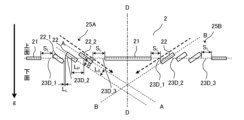
- FIG. 3 is a schematic diagram of the fin portion 21 of the corrugated fin 2 according to the first embodiment when viewed from above.
- DD indicates a center line passing through the center of the fin portion 21 in the depth direction.
- the flat heat exchanger tube 1 has a flat cross section.
- the longitudinal direction of the flat shape is parallel to the depth direction, which is the direction of air flow, and the outer surface along the depth direction is planar.
- the outer surface of the flat shape along the transverse direction perpendicular to the longitudinal direction is a curved heat exchanger tube.
- the flat heat exchanger tube 1 is a multi-hole flat heat exchanger tube that has a plurality of holes that serve as refrigerant flow paths inside the tube.
- the holes in the flat heat exchanger tubes 1 serve as flow paths for the refrigerant between the lower header 3A and the upper header 3B shown in FIG. 1, and are formed along the height direction.
- Each flat heat exchanger tube 1 is arranged with a space between adjacent flat heat exchanger tubes 1 so that the outer surfaces along the longitudinal side of the flat shape face each other.
- the corrugated fin 2 has one end portion 2B that protrudes upstream from between the opposing flat heat exchanger tubes 1 in the air flow direction. Except for the top portion 2A at the one end portion 2B, the corrugated top portion 2A of the corrugated fin 2 and the flat surface of the flat heat exchanger tube 1 are in surface contact with each other. The contact portions are brazed and joined using a brazing filler metal.
- the material of the plate material of the corrugated fin 2 is, for example, an aluminum alloy.
- the surface of the plate material is clad with a brazing material layer.
- the cladding brazing material layer is, for example, an aluminum-silicon-based brazing material containing aluminum.
- the thickness of the plate material is approximately 30 ⁇ m to 200 ⁇ m.
- Each fin portion 21 has a louver portion 22 which is a heat transfer promoting portion projecting upward, and a first drainage space 23D_1.
- the louver portion 22 is an elongated wing plate.
- a plurality of louver portions 22 are provided in each fin portion 21 in a row at intervals in the depth direction, which is the air flow direction. That is, the plurality of louver parts 22 are lined up along the airflow.
- FIG. 2 shows how the condensed water 4 generated on the fin portion 21 is drained into the first drainage space 23D_1.
- the fin section 21 includes a first heat transfer promoting section group 25A and a second heat transfer promoting section group 25B.
- the first heat transfer promoting section group 25A is provided in an upstream region in the air flow direction with respect to the center line DD of the fin section 21.
- the first heat transfer promoting section group 25A includes two louver sections 22, a first drainage space 23D_1, a second drainage space 23D_2, and a third drainage space 23D_3.
- two louver sections 22 are shown in FIG. 3, three louver sections 22 or four or more louver sections 22 may be provided as shown in FIG.
- the plurality of louver sections 22 include a first louver section 22_1 disposed at the most upstream side in the air flow direction, and a second louver section 22_2 disposed at the most downstream side in the air flow direction.
- the first drainage space 23D_1 is provided between the first louver part 22_1 and the fin part 21 on the upstream side in the flow direction closest to the first louver part 22_1.
- the first drainage space 23D_1 is an opening that passes through the fin portion 21, and has a rectangular shape when viewed from above perpendicular to the flat surface of the fin portion 21.
- the second drainage space 23D_2 is provided between adjacent louver parts 22.
- the louver portion 22 of this embodiment is formed by cutting and raising a plate material that constitutes the fin portion 21 .
- the space between the fin parts 21 formed by cutting and raising is the second drainage space 23D_2.
- the third drainage space 23D_3 is provided between the second louver part 22_2 and the fin part 21 on the downstream side in the flow direction closest to the second louver part 22_2.
- the third drainage space 23D_3 is an opening that passes through the fin portion 21, and has a rectangular shape when viewed from above perpendicularly to the flat surface of the fin portion 21.
- the area of the first drainage space 23D_1 is wider than the area of the second drainage space 23D_2. Furthermore, in this embodiment, the area of the third drainage space 23D_3 when viewed perpendicularly to the fin portion 21 is larger than the area of the second drainage space 23D_2.
- the second heat transfer promoting section group 25B is provided in a region downstream of the center line DD of the fin section 21 in the air flow direction.
- the second heat transfer promoting section group 25B includes two louver sections 22, a first drainage space 23D_1, a second drainage space 23D_2, and a third drainage space 23D_3.
- two louver sections 22 are shown in FIG. 3, three louver sections 22 or four or more louver sections 22 may be provided as shown in FIG.
- the plurality of louver sections 22 include a first louver section 22_1 disposed at the most upstream side in the air flow direction, and a second louver section 22_2 disposed at the most downstream side in the air flow direction.
- the first drainage space 23D_1 is provided between the first louver part 22_1 and the fin part 21 on the upstream side in the flow direction closest to the first louver part 22_1.
- the first drainage space 23D_1 is an opening that passes through the fin portion 21, and has a rectangular shape when viewed from above perpendicular to the flat surface of the fin portion 21.
- the second drainage space 23D_2 is provided between adjacent louver parts 22.
- the third drainage space 23D_3 is provided between the second louver part 22_2 and the fin part 21 on the downstream side in the flow direction closest to the second louver part 22_2.
- the third drainage space 23D_3 is an opening that passes through the fin portion 21, and has a rectangular shape when viewed from above perpendicularly to the flat surface of the fin portion 21.
- the area of the first drainage space 23D_1 is wider than the area of the second drainage space 23D_2. Furthermore, in this embodiment, the area of the third drainage space 23D_3 when viewed perpendicularly to the fin portion 21 is larger than the area of the second drainage space 23D_2.
- FIG. 4 is a schematic vertical cross-sectional view of the fin portion 21 of the corrugated fin 2 according to the first embodiment.
- FIG. 4 shows an example in which three louver parts 22 are provided in the first heat transfer promoting part group 25A along the air flow direction. Further, in the second heat transfer promoting section group 25B, an example is shown in which three louver sections 22 are provided along the air flow direction.
- AA A virtual line indicating the inclination of the louver portion 22 of the first heat transfer promoting portion group 25A with respect to the fin portion 21.
- BB A virtual line indicating the inclination of the louver portion 22 of the second heat transfer promoting portion group 25B with respect to the fin portion 21.
- LL is the distance between adjacent louver parts 22 in a plane along the fin part 21.
- L P is the distance between the centers of adjacent louver parts 22 on the plane along the fin part 21 .
- Ls is the distance between the gaps between adjacent louver parts 22.
- ⁇ is the inclination angle of the louver portion 22 with respect to the fin portion 21. LL and LP are equal.
- S L on the upstream side in the air flow direction in the first heat transfer promoting section group 25A is the distance between the first louver section 22_1 and the fin section 21 on the upstream side in the flow direction closest to the first louver section 22_1. It is. That is, SL on the upstream side in the air flow direction in the first heat transfer promoting section group 25A is the length of the first drainage space 23D_1 when viewed perpendicularly to the flat surface of the fin section 21.
- S L on the downstream side in the air flow direction in the first heat transfer promoting section group 25A is the distance between the second louver section 22_2 and the fin section 21 on the downstream side in the flow direction closest to the second louver section 22_2. It is. That is, SL on the downstream side in the air flow direction in the first heat transfer promoting section group 25A is the length of the third drainage space 23D_3 when viewed perpendicularly to the flat surface of the fin section 21.
- LL in the first heat transfer promoting section group 25A is the distance between adjacent louver sections 22 in the first heat transfer promoting section group 25A. That is, LL in the first heat transfer promoting section group 25A is the length of the second drainage space 23D_2 in the air flow direction when viewed perpendicularly to the fin section 21.
- the length of S L on the downstream side in the air flow direction in the first heat transfer promoting section group 25A is longer than the length of L L in the first heat transfer promoting section group 25A.
- S L on the upstream side in the air flow direction in the second heat transfer promoting section group 25B is the distance between the first louver section 22_1 and the fin section 21 on the upstream side in the flow direction closest to the first louver section 22_1. It is. That is, SL on the upstream side in the air flow direction in the first heat transfer promoting section group 25A is the length of the first drainage space 23D_1 when viewed perpendicularly to the flat surface of the fin section 21.
- S L on the downstream side in the air flow direction in the second heat transfer promoting section group 25B is the distance between the second louver section 22_2 and the fin section 21 on the downstream side in the flow direction closest to the second louver section 22_2. It is. That is, SL on the downstream side in the air flow direction in the first heat transfer promoting section group 25A is the length of the third drainage space 23D_3 when viewed perpendicularly to the flat surface of the fin section 21.
- LL in the second heat transfer promoting section group 25B is the distance between adjacent louver sections 22 in the second heat transfer promoting section group 25B. That is, LL in the second heat transfer promoting section group 25B is the length of the second drainage space 23D_2 in the air flow direction when viewed perpendicularly to the fin section 21.
- the length of S L on the downstream side in the air flow direction in the second heat transfer promoting section group 25B is longer than the length of L L in the second heat transfer promoting section group 25B.
- the heat exchanger 10 of the first embodiment has a first drainage space 23D_1 which is wider than a second drainage space 23D_2 between the adjacent louver parts 22 between the fin part 21 and the louver part 22 adjacent to the fin part 21. and a third drainage space 23D_3. Therefore, the relationship S L >L L holds true.
- first heat transfer promoting section group 25A shown in FIG. 4 three louver sections 22 are arranged in parallel with an interval between them.
- first heat transfer promoting section group 25A the gap formed on the outside of the louver section 22 at the end is larger than the gap between the louver sections 22 in the first heat transfer promoting section group 25A.
- second heat transfer promoting part group 25B the gap formed on the outside of the louver part 22 at the end is larger than the gap between the louver parts 22 in the second heat transfer promoting part group 25B.
- a part of the outer periphery of the first drainage space 23D_1 is formed by the edge of the first louver part 22_1 on the most upstream side. That is, the first louver portion 22_1 and the first drainage space 23D_1 are directly adjacent to each other without any other member or space between them.
- a part of the outer periphery of the third drainage space 23D_3 is formed by the edge of the second louver portion 22_2 on the most downstream side. In other words, the second louver portion 22_2 and the third drainage space 23D_3 are directly adjacent to each other without any other member or space between them.
- the shapes of the first drainage space 23D_1 and the third drainage space 23D_3 have been described as having a rectangular shape when viewed from above as shown in FIG. 3, but the shape is limited to a rectangular shape. It's not a thing.
- FIG. 5 is a schematic top view of the fin portion 21 of the corrugated fin 2 having the first drainage space 23D_1 and the third drainage space 23D_3 according to the modified example of the first embodiment.
- the first drainage space 23D_1 and the third drainage space 23D_3 include a curved line in part of their shape when viewed perpendicularly to the fin portion 21.
- the first drainage space 23D_1 and the third drainage space 23D_3 have a D-shaped outer shape.
- the edge of the louver portion 22 that defines the first drainage space 23D_1, extending from one flat heat exchanger tube 1 toward the other flat heat exchanger tube 1, is a curve
- a part of the shape of the first drainage space 23D_1 is It is a curved line.
- the edges of the fin portions 21 that define the third drainage space 23D_3, extending from one flat heat exchanger tube 1 toward the other flat heat exchanger tube 1, are curved, the shape of the third drainage space 23D_3 is uniform. The part is curved.
- the curves of the first drainage space 23D_1 and the third drainage space 23D_3 are curves that are convex in the air flow direction, with the apex 2A located between the flat heat exchanger tubes 1.
- FIG. 5 shows an example in which the curves of the first drainage space 23D_1 and the third drainage space 23D_3 are curves that are convex in the air flow direction, they are curves that are convex in the opposite direction to the air flow direction. It may be a curve.
- condensed water 4 generated on the corrugated fins 2 passes through the drainage space between the louver parts 22 (second drainage space 23D_2 in the embodiment) and flows down.
- the amount of the condensed water 4 flowing from the fin section 21 adjacent to the louver section 22 toward the louver section 22 in the air flow direction is It is larger than the amount of condensed water 4 flowing on the surface.
- the first drainage space 23D_1 is provided between the first louver part 22_1 and the fin part 21 on the upstream side in the air flow direction closest to the first louver part 22_1.
- a second drainage space 23D_2 is provided between the adjacent louver parts 22, and the area of the first drainage space 23D_1 when viewed perpendicularly to the fin part 21 is larger than the area of the second drainage space 23D_2. wide.
- the condensed water 4 generated on the flat fin portion 21 of the corrugated fin 2 is pushed by the air flow and flows on the fin portion 21 from upstream to downstream.
- the air then reaches the first drainage space 23D_1 between the first louver part 22_1, which is a heat transfer promoting part, and the fin part 21 on the upstream side in the air flow direction, and flows down from the first drainage space 23D_1. Since the first drainage space 23D_1 has a relatively large area as described in the first embodiment, most of the condensed water 4 flows down from the first drainage space 23D_1. Therefore, drainage of condensed water 4 generated on the fin portions 21 of the corrugated fins 2 is improved.
- drainability refers to the amount of water drained from the heat exchanger 10 per unit time.
- first drainage space 23D_1 between the adjacent fin part 21 and the first louver part 22_1 relatively large, it is possible to prevent the condensed water 4 from staying in the first drainage space 23D_1, that is, between the fin part 21 and the first louver part. Bridging of the condensed water 4 with the portion 22_1 can be suppressed.
- the condensed water 4 flows down the gap between the louver parts 22 and is drained, but at this time, much of the condensed water 4 is introduced from the fin parts 21. Therefore, it has been found that by providing the first drainage space 23D_1 which is wider than the second drainage space 23D_2, drainage performance can be effectively improved. Further, the area of the second drainage space 23D_2 provided between the louver parts 22 of the corrugated fins 2 is smaller than the area of the first drainage space 23D_1. Therefore, the decrease in the heat transfer area of the corrugated fins 2 can be reduced, and thereby the decrease in heat transfer performance can be suppressed.
- the first drainage space 23D_1 is provided in an area on the upstream side of the air flow where the amount of moisture contained in the air is large, so that frost can be retained.
- the number of areas to do increases. That is, more frost adheres to and is retained around the first drainage space 23D_1.
- the plurality of louver sections 22 include the second louver section 22_2 disposed on the most downstream side in the air flow direction;
- a third drainage space 23D_3 is provided between the fin part 21 on the downstream side in the air flow direction closest to the part 22_2, and the area of the third drainage space 23D_3 when viewed perpendicularly to the fin part 21 is: It is wider than the area of the second drainage space 23D_2.
- the condensed water 4 generated on the flat fin portion 21 of the corrugated fin 2 is pushed by the air flow and flows on the fin portion 21 from upstream to downstream. Then, it reaches the third drainage space 23D_3 between the second louver part 22_2 and the fin part 21, which are heat transfer promoting parts located on the downstream side in the air flow direction, and flows down from the third drainage space 23D_3. Since the third drainage space 23D_3 has a relatively large area as described in the first embodiment, most of the condensed water 4 flows down from the third drainage space 23D_3. Therefore, drainage of condensed water 4 generated on the fin portions 21 of the corrugated fins 2 is improved.
- the third drainage space 23D_3 between the adjacent fin part 21 and the second louver part 22_2 relatively large, it is possible to prevent the condensed water 4 from staying in the third drainage space 23D_3, that is, between the fin part 21 and the second louver part. Bridging of the condensed water 4 with the portion 22_2 can be suppressed.
- the heat transfer performance of the portion of the fin portion 21 with low fin efficiency Drainage performance can be further improved while suppressing the decrease in water as much as possible.
- the shapes of the first drainage space 23D_1 and the third drainage space 23D_3 are such that the opening space is larger toward the center of the opening area, the drainage performance can be further improved while suppressing deterioration of heat transfer performance as much as possible.
- FIG. 6 is a schematic top view of the corrugated fin 2 according to the second embodiment. Note that the same parts as in FIG. 3 are given the same reference numerals, and different parts will be explained here.
- the opening area of the first drainage space 23D_1 in the first heat transfer promoting part group 25A is larger than the opening area of the third drainage space 23D_3 in the first heat transfer promoting part group 25A. It's also big.
- the sum of the opening areas of the plurality of louvers 22 in the first heat transfer promoting part group 25A is larger than the sum of the opening areas of the plurality of louvers 22 in the second heat transfer promoting part group 25B.
- A1 the sum of the opening areas of the plurality of louvers 22 in the first heat transfer promoting part group 25A
- B1 B 1
- a 1 > B 1
- the total opening area is the opening area of the first drainage space 23D_1, the second drainage space 23D_2, and the third drainage space 23D_3.
- the amount of heat exchanged by the heat exchanger 10 is large in the upstream portion of the fin portion 21 in the air flow direction where the temperature difference between the air and the temperature of the refrigerant flowing in the flat heat exchanger tube 1 is large. Therefore, the amount of condensed water 4 generated is also greater on the upstream side in the air flow direction.
- the total opening area of the drainage spaces in the first heat transfer promoting section group 25A on the upstream side of the center line DD of the fin section 21 in the air flow direction is It is larger than the total opening area of the drainage spaces in the second heat transfer promoting section group 25B on the downstream side in the flow direction. Therefore, the heat exchanger 10 of the second embodiment has improved drainage performance compared to the heat exchanger 10 of the first embodiment.
- the first drainage space 23D_1 on the upstream side in the air flow direction has a larger opening area than the third drainage space 23D_3 on the downstream side in the air flow direction. Since it is also large, drainage performance is further improved.
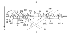
- FIG. 7 is a side sectional view of the fin portion 21 of the corrugated fin 2 according to the third embodiment. Note that the same parts as in FIG. 4 are given the same reference numerals, and different parts will be explained here.
- the plurality of louver parts 22 in the first heat transfer promoting part group 25A are arranged at an angle with respect to the fin part 21.
- the fin portion 21 on the upstream side in the air flow direction closest to the first louver portion 22_1 has a first slope portion 26_1 that slopes parallel to the slope direction of the first louver portion 22_1.
- the fin part 21 on the downstream side in the air flow direction closest to the second louver part 22_2 has a second slope part 26_2 that slopes parallel to the slope direction of the second louver part 22_2.
- the first inclined portion 26_1 of the fin portion 21 on the upstream side in the air flow direction closest to the first louver portion 22_1 in the first heat transfer promoting portion group 25A is formed in a direction that protrudes toward the lower surface side with respect to the fin portion 21. Ru.
- the second inclined portion 26_2 of the fin portion 21 on the downstream side in the air flow direction closest to the first louver portion 22_1 in the first heat transfer promoting portion group 25A is formed in a direction that protrudes toward the upper surface side with respect to the fin portion 21. Ru.
- the area of the first drainage space 23D_1 provided between the first inclined part 26_1 and the first louver part 22_1 in the first heat transfer promoting part group 25A when viewed perpendicularly to the fin part 21 is the same as that of the adjacent louver. It is larger than the area of the second drainage space 23D_2 provided between the sections 22.
- the area of the third drainage space 23D_3 provided between the second inclined portion 26_2 and the second louver portion 22_2 in the first heat transfer promoting portion group 25A is equal to the area of the adjacent louver. It is larger than the area of the second drainage space 23D_2 provided between the sections 22.
- the plurality of louver parts 22 in the second heat transfer promoting part group 25B are arranged at an angle with respect to the fin part 21.
- the fin portion 21 on the upstream side in the air flow direction closest to the first louver portion 22_1 has a first slope portion 26_1 that slopes parallel to the slope direction of the first louver portion 22_1.
- the fin part 21 on the downstream side in the air flow direction closest to the second louver part 22_2 has a second slope part 26_2 that slopes parallel to the slope direction of the second louver part 22_2.
- the first inclined part 26_1 of the fin part 21 on the upstream side in the air flow direction closest to the first louver part 22_1 in the second heat transfer promoting part group 25B is formed in a direction that protrudes toward the upper surface side with respect to the fin part 21. Ru.
- the second inclined portion 26_2 of the fin portion 21 on the downstream side in the air flow direction closest to the first louver portion 22_1 in the second heat transfer promoting portion group 25B is formed in a direction protruding toward the lower surface side with respect to the fin portion 21. Ru.
- the first drainage space 23D_1 provided between the first inclined part 26_1 and the first louver part 22_1 in the second heat transfer promoting part group 25B is larger than the second drainage space 23D_2 provided between the adjacent louver parts 22. It's also big.
- the third drainage space 23D_3 provided between the second inclined part 26_2 and the second louver part 22_2 in the second heat transfer promoting part group 25B is larger than the second drainage space 23D_2 provided between the adjacent louver parts 22. It's also big.
- the area of the corrugated fins 2 that contributes to heat exchange is increased by the first sloped portion 26_1 and the second sloped portion 26_2, so that the heat transfer performance of the corrugated fins 2 can be improved.
- the first drainage space 23D_1 of the first heat transfer promoting section group 25A is viewed along the inclination of the louver section 22 (in the direction of the thick broken line arrow in FIG. 7), the first inclined section 26_1 and the first louver section 22_1, a flow path along this inclination is formed.
- the flow path between the first inclined portion 26_1 and the first louver portion 22_1 becomes a drainage path for the condensed water 4. Therefore, compared to the case where the first inclined portion 26_1 is not provided, the drainage performance of the corrugated fin 2 can be improved while improving the heat transfer performance.
- the second slope part 26_2 makes the third drainage space 23D_3 a larger opening when viewed along the slope of the louver part 22 (in the direction of the thick arrow in FIG. 7). Become. Therefore, the drainage performance of the corrugated fins 2 can be improved.
- FIG. 8 is a side sectional view of the fin portion 21 of the corrugated fin 2 according to the fourth embodiment. Note that the same parts as in FIG. 4 are given the same reference numerals, and different parts will be explained here.
- a flat drainage slit 27 which is a fourth drainage space for draining condensed water 4, is provided in the fin portion 21 near the center of the fin in the air flow direction.
- the flat drainage slit 27 is provided between the first heat transfer promoting section group 25A and the second heat transfer promoting section group 25B.
- FIG. 8 is not shown, as can be seen from FIGS. 1 and 2, a plurality of fin portions 21 are arranged in a line in the vertical direction, and the flat drainage slits 27 of each fin portion 21 are also arranged in a line in a vertical direction. Placed.
- the orientation of the louver portion 22 is such that the condensed water 4 (not shown) flows into the flat drain slit 27 of the fin portion 21 on the lower stage of the fin portion 21 where the louver portion 22 is provided. They are oriented so that they can gather together.
- the dashed arrow in FIG. 8 represents the direction in which the condensed water 4 is drained.
- the condensed water 4 that has flowed down along the surface of the louver section 22 falls toward the flat section drainage slit 27 of the fin section 21 located at the lower stage of this louver section 22, and the condensed water 4 flows down along the surface of the louver section 22 and falls toward the flat section drainage slit 27 of the fin section 21 located at the lower stage of this louver section 22. Falling down from 27.
- the louver portions 22 By arranging the louver portions 22 in this manner, the drainage performance of the condensed water 4 can be improved.
- the direction of inclination of the plurality of louvers 22 in the first heat transfer promoting part group 25A with respect to the fin part 21 is such that the plurality of louver parts 22 in the second heat transfer promoting part group 25B are inclined with respect to the flat part drainage slit 27.
- This direction is opposite to the direction of inclination with respect to the fin portion 21. Therefore, both the condensed water 4 that has fallen from the first heat transfer promoting section group 25A and the condensed water 4 that has fallen from the second heat transfer promoting section group 25B flow toward one flat drainage slit 27.
- FIG. 9 is a schematic top view of the fin portion 21 of the corrugated fin 2 according to the fourth embodiment. Note that the same parts as in FIG. 3 are given the same reference numerals, and different parts will be explained here.
- the opening area of the flat drainage slit 27 is larger than the total opening area of the first heat transfer promoting section group 25A.
- the total opening area of the first heat transfer promoting section group 25A is the sum of the opening areas of the first drainage space 23D_1, the second drainage space 23D_2, and the third drainage space 23D_3.
- S s is the distance of the flat drainage slit 27 in the air flow direction.
- the flat drainage slit 27 is one rectangular opening.
- the flat drainage slit 27 may be configured with a plurality of openings. good.
- FIG. 10 is a side sectional view of the fin portion 21 of the corrugated fin 2 according to a modification of the fourth embodiment.
- the same parts as in FIG. 4 are given the same reference numerals, and different parts will be explained here.
- FIG. 11 is a schematic top view of the fin portion 21 of the corrugated fin 2 according to a modification of the fourth embodiment.
- the same parts as in FIG. 3 are given the same reference numerals, and different parts will be explained here.
- the opening shape of the flat drainage slit 27 is not limited to a rectangular shape.
- the opening area of the flat drainage slit 27 is larger than the total opening area of the first heat transfer promoting section group 25A.
- the fin portions 21 are arranged vertically. Therefore, in the corrugated fin 2, the condensed water 4 introduced from the first heat transfer promoting part group 25A and the second heat transfer promoting part group 25B of the upper fin part 21 is drained from the flat part of the lower fin part 21.
- the slit 27 allows drainage. Therefore, the drainage performance of the heat exchanger 10 is improved.
- FIG. 12 is a side sectional view of the fin portion 21 of the corrugated fin 2 according to the fifth embodiment.
- the same parts as in FIG. 4 are given the same reference numerals, and different parts will be explained here.
- the inclination angle ⁇ of the louver part 22 with respect to the flat surface of the fin part 21 is different from the inclination angle ⁇ of the louver part 22 adjacent to each other in the air flow direction.
- the inclination angle of the louver part 22 with respect to the first louver part 22_1 is ⁇ 1
- the inclination angle with respect to the louver part 22 is ⁇ 2
- the inclination angle of the second louver part 22_2 is ⁇ 3.
- ⁇ 1 ⁇ 2 ⁇ 3 holds true.
- the inclination angle ⁇ 1, the inclination angle ⁇ 2, and the inclination angle ⁇ 3 in the first heat transfer promoting portion group 25A are different from each other.
- the inclination angle ⁇ 3 of the second louver portion 22_2 in the first heat transfer promoting portion group 25A is larger than the inclination angle ⁇ 1 of the first louver portion 22_1.
- the inclination angle ⁇ 1, the inclination angle ⁇ 2, and the inclination angle ⁇ 3 in the second heat transfer promoting portion group 25B are different from each other.
- the inclination angle ⁇ 3 of the second louver portion 22_2 in the second heat transfer promoting portion group 25B is larger than the inclination angle ⁇ 1 of the first louver portion 22_1.
- the inclination angle ⁇ 2 of the second louver part 22_2 on the downstream side in the air flow direction is relative to the inclination angle ⁇ 1 of the first louver part 22_1 on the upstream side in the air flow direction. is large. Therefore, the heat transfer coefficient on the upstream side in the flow direction of air with a large amount of frost formation can be suppressed, and the frost resistance can be improved.
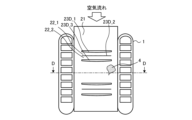
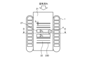
- FIG. 13 is a diagram showing the configuration of an air conditioner A according to Embodiment 6.
- an air conditioner A will be described as an example of a refrigeration cycle device.
- the heat exchanger 10 is used as an outdoor heat exchanger 230.
- the present invention is not limited to this, and may be used as the indoor heat exchanger 110 or both the outdoor heat exchanger 230 and the indoor heat exchanger 110.
- a refrigerant circuit is configured by connecting an outdoor unit 200 and an indoor unit 100 through gas refrigerant piping 300 and liquid refrigerant piping 400.
- the outdoor unit 200 includes a compressor 210, a four-way valve 220, an outdoor heat exchanger 230, and an outdoor fan 240.
- the air conditioner A of Embodiment 1 it is assumed that one outdoor unit 200 and one indoor unit 100 are connected by piping.
- the compressor 210 compresses and discharges the sucked refrigerant.
- the capacity of the compressor 210 can be changed by arbitrarily changing the operating frequency of the compressor 210 using, for example, an inverter circuit.
- the four-way valve 220 is a valve that switches the flow of refrigerant depending on, for example, cooling operation and heating operation.
- the outdoor heat exchanger 230 exchanges heat between the refrigerant and outdoor air. For example, during heating operation, it functions as an evaporator and evaporates the refrigerant. Also, during cooling operation, it functions as a condenser, condensing and liquefying the refrigerant.
- the outdoor fan 240 sends outdoor air to the outdoor heat exchanger 230 and promotes heat exchange in the outdoor heat exchanger 230.
- the indoor heat exchanger 110 exchanges heat between indoor air to be air-conditioned and a refrigerant, for example. During heating operation, it functions as a condenser, condensing and liquefying the refrigerant. Also, during cooling operation, it functions as an evaporator and evaporates and vaporizes the refrigerant.
- the indoor unit 100 includes an indoor heat exchanger 110, an expansion valve 120, and an indoor fan 130.
- the expansion valve 120 such as a throttle device, depressurizes and expands the refrigerant.
- the opening degree is adjusted based on instructions from a control device (not shown) or the like.
- the indoor heat exchanger 110 performs heat exchange between indoor air, which is a space to be air-conditioned, and a refrigerant.
- a condenser to condense and liquefy the refrigerant.
- it functions as an evaporator and evaporates and vaporizes the refrigerant.
- the indoor fan 130 causes indoor air to pass through the indoor heat exchanger 110, and supplies the air that has passed through the indoor heat exchanger 110 into the room.
- each device of the air conditioner A will be explained based on the flow of refrigerant.
- the high temperature and high pressure gas refrigerant compressed and discharged by the compressor 210 passes through the four-way valve 220 and flows into the indoor heat exchanger 110. While passing through the indoor heat exchanger 110, the gas refrigerant condenses and liquefies, for example, by exchanging heat with the air in the air-conditioned space. The condensed and liquefied refrigerant passes through the expansion valve 120. When the refrigerant passes through the expansion valve 120, its pressure is reduced.
- the refrigerant whose pressure is reduced by the expansion valve 120 and becomes a gas-liquid two-phase state passes through the outdoor heat exchanger 230.
- the refrigerant that is evaporated and gasified by exchanging heat with the outdoor air sent from the outdoor fan 240 passes through the four-way valve 220 and is sucked into the compressor 210 again.
- the refrigerant of the air conditioner A circulates to perform air conditioning related to heating.
- the high temperature and high pressure gas refrigerant compressed and discharged by the compressor 210 passes through the four-way valve 220 and flows into the outdoor heat exchanger 230.
- the refrigerant passes through the outdoor heat exchanger 230 and is condensed and liquefied by exchanging heat with outdoor air supplied by the outdoor fan 240 , and then passes through the expansion valve 120 .
- the expansion valve 120 When the refrigerant passes through the expansion valve 120, its pressure is reduced.
- the refrigerant whose pressure is reduced by the expansion valve 120 and becomes a gas-liquid two-phase state passes through the indoor heat exchanger 110.
- the refrigerant that is evaporated and gasified by exchanging heat with the air in the air-conditioned space passes through the four-way valve 220 and is sucked into the compressor 210 again.
- the refrigerant of the air conditioner A circulates and air conditioning related to cooling is performed.
- the heat exchanger 10 acts as an evaporator
- the surfaces of the flat heat exchanger tubes 1 and corrugated fins 2 have a temperature lower than that of the air passing through the heat exchanger 10. Therefore, moisture in the air condenses on the surfaces of the flat heat exchanger tubes 1 and the corrugated fins 2, and condensed water 4 is precipitated.
- the air temperature is even lower, the fin surface temperature drops below freezing, and the condensed water 4 on the fin surface freezes and grows as frost, blocking the air flow and increasing the air flow resistance.
- the amount of air flowing through the heat exchanger 10 decreases, thereby reducing the performance of the heat exchanger 10.
- the heat exchanger 10 shown in Embodiment 1, Embodiment 2, Embodiment 3, Embodiment 4, and Embodiment 5 is used. Therefore, in the heat exchanger 10, retention of condensed water 4 can be suppressed and drainage performance can be improved. Furthermore, since the first drainage space 23D_1 and the third drainage space 23D_3 increase the area for retaining frost, it is possible to extend the blockage time of the air flow between the fin portions 21, and improve frost resistance. As a result, the heat exchanger 10 of the air conditioner A of Embodiment 6 can reduce the decrease in the heat transfer area of the corrugated fins 2 during frost conditions, and can suppress the decrease in heat transfer performance. .
- the louver part 22 is also called a heat transfer promotion part, and the flat part drainage slit 27 is also called a fourth drainage space.
Abstract
Cet échangeur de chaleur comprend : une pluralité de tubes de transfert de chaleur disposés en parallèle avec des espaces entre eux dans une direction croisant une direction d'écoulement d'air ; et des ailettes ondulées disposées entre la pluralité de tubes de transfert de chaleur, les ailettes ondulées étant pourvues de parties d'ailettes qui sont des plans plats, et d'un groupe ou d'une pluralité de groupes de parties favorisant le transfert de chaleur qui s'étendent d'un à un autre de la pluralité de tubes de transfert de chaleur adjacents et qui ont une pluralité de parties favorisant le transfert de chaleur agencées de manière inclinée par rapport aux parties d'ailettes. La pluralité de parties favorisant le transfert de chaleur comprennent une première partie favorisant le transfert de chaleur disposée le plus en amont dans la direction d'écoulement d'air. Un premier espace de drainage est disposé entre la première partie favorisant le transfert de chaleur et la partie d'ailette sur le côté amont dans la direction d'écoulement d'air qui est la plus proche de la première partie favorisant le transfert de chaleur, et un second espace de drainage est disposé entre les parties favorisant le transfert de chaleur adjacentes, la surface du premier espace de drainage étant supérieure à la surface du second espace de drainage lorsque les parties d'ailettes sont vues verticalement.
Priority Applications (2)
| Application Number | Priority Date | Filing Date | Title |
|---|---|---|---|
| JP2022571190A JP7353518B1 (ja) | 2022-04-19 | 2022-04-19 | 熱交換器及び空気調和装置 |
| PCT/JP2022/018182 WO2023203640A1 (fr) | 2022-04-19 | 2022-04-19 | Échangeur de chaleur et climatiseur |
Applications Claiming Priority (1)
| Application Number | Priority Date | Filing Date | Title |
|---|---|---|---|
| PCT/JP2022/018182 WO2023203640A1 (fr) | 2022-04-19 | 2022-04-19 | Échangeur de chaleur et climatiseur |
Publications (1)
| Publication Number | Publication Date |
|---|---|
| WO2023203640A1 true WO2023203640A1 (fr) | 2023-10-26 |
Family
ID=88143985
Family Applications (1)
| Application Number | Title | Priority Date | Filing Date |
|---|---|---|---|
| PCT/JP2022/018182 WO2023203640A1 (fr) | 2022-04-19 | 2022-04-19 | Échangeur de chaleur et climatiseur |
Country Status (2)
| Country | Link |
|---|---|
| JP (1) | JP7353518B1 (fr) |
| WO (1) | WO2023203640A1 (fr) |
Citations (7)
| Publication number | Priority date | Publication date | Assignee | Title |
|---|---|---|---|---|
| JP2010025482A (ja) * | 2008-07-22 | 2010-02-04 | Daikin Ind Ltd | 熱交換器 |
| JP2015183908A (ja) * | 2014-03-24 | 2015-10-22 | 株式会社デンソー | 熱交換器 |
| WO2018154806A1 (fr) * | 2017-02-21 | 2018-08-30 | 三菱電機株式会社 | Échangeur de chaleur et climatiseur |
| JP2020133991A (ja) * | 2019-02-18 | 2020-08-31 | 株式会社デンソー | 複合型熱交換器 |
| WO2021095538A1 (fr) * | 2019-11-11 | 2021-05-20 | 三菱電機株式会社 | Échangeur de chaleur, dispositif à cycle frigorifique et procédé de fabrication d'ailette ondulée |
| WO2021095087A1 (fr) * | 2019-11-11 | 2021-05-20 | 三菱電機株式会社 | Échangeur de chaleur et dispositif à cycle frigorifique |
| WO2021234964A1 (fr) * | 2020-05-22 | 2021-11-25 | 三菱電機株式会社 | Échangeur de chaleur et conditionneur d'air |
-
2022
- 2022-04-19 JP JP2022571190A patent/JP7353518B1/ja active Active
- 2022-04-19 WO PCT/JP2022/018182 patent/WO2023203640A1/fr active Application Filing
Patent Citations (7)
| Publication number | Priority date | Publication date | Assignee | Title |
|---|---|---|---|---|
| JP2010025482A (ja) * | 2008-07-22 | 2010-02-04 | Daikin Ind Ltd | 熱交換器 |
| JP2015183908A (ja) * | 2014-03-24 | 2015-10-22 | 株式会社デンソー | 熱交換器 |
| WO2018154806A1 (fr) * | 2017-02-21 | 2018-08-30 | 三菱電機株式会社 | Échangeur de chaleur et climatiseur |
| JP2020133991A (ja) * | 2019-02-18 | 2020-08-31 | 株式会社デンソー | 複合型熱交換器 |
| WO2021095538A1 (fr) * | 2019-11-11 | 2021-05-20 | 三菱電機株式会社 | Échangeur de chaleur, dispositif à cycle frigorifique et procédé de fabrication d'ailette ondulée |
| WO2021095087A1 (fr) * | 2019-11-11 | 2021-05-20 | 三菱電機株式会社 | Échangeur de chaleur et dispositif à cycle frigorifique |
| WO2021234964A1 (fr) * | 2020-05-22 | 2021-11-25 | 三菱電機株式会社 | Échangeur de chaleur et conditionneur d'air |
Also Published As
| Publication number | Publication date |
|---|---|
| JP7353518B1 (ja) | 2023-09-29 |
| JPWO2023203640A1 (fr) | 2023-10-26 |
Similar Documents
| Publication | Publication Date | Title |
|---|---|---|
| JP6734002B1 (ja) | 熱交換器および冷凍サイクル装置 | |
| JP6466631B1 (ja) | 熱交換器およびこれを備えた空気調和機 | |
| JP7292510B2 (ja) | 熱交換器及び空気調和機 | |
| WO2021234958A1 (fr) | Échangeur de chaleur, unité extérieure équipée d'un échangeur de chaleur, et conditionneur d'air équipé d'une unité extérieure | |
| JP6719657B2 (ja) | 熱交換器および冷凍サイクル装置 | |
| WO2018207321A1 (fr) | Échangeur de chaleur et dispositif à cycle frigorifique | |
| JP7353518B1 (ja) | 熱交換器及び空気調和装置 | |
| JP7381909B2 (ja) | 伝熱管、及び、熱交換器 | |
| WO2023170834A1 (fr) | Échangeur de chaleur et dispositif à cycle de réfrigération équipé de l'échangeur de chaleur | |
| JP7313334B2 (ja) | 熱交換器及び冷凍サイクル装置 | |
| WO2022219719A1 (fr) | Échangeur de chaleur et dispositif à cycle de réfrigération | |
| WO2021205905A1 (fr) | Échangeur de chaleur, climatiseur et procédé de fabrication d'un échangeur de chaleur | |
| US20240159481A1 (en) | Heat exchanger and refrigeration cycle apparatus | |
| US20240159474A1 (en) | Heat exchanger and refrigeration cycle apparatus | |
| CN219914070U (zh) | 微通道换热器和空调器 | |
| WO2023199400A1 (fr) | Échangeur de chaleur et dispositif à cycle de réfrigération | |
| CN220083746U (zh) | 微通道换热器和空调器 | |
| JP7399286B2 (ja) | 熱交換器および冷凍サイクル装置 | |
| JP7150157B2 (ja) | 熱交換器および冷凍サイクル装置 | |
| WO2021234954A1 (fr) | Échangeur de chaleur, unité extérieure et dispositif à cycle de réfrigération | |
| WO2023032155A1 (fr) | Échangeur de chaleur, dispositif de cycle de réfrigération et procédé de fabrication d'un échangeur de chaleur | |
| WO2023195193A1 (fr) | Échangeur de chaleur, climatiseur équipé d'un échangeur de chaleur et procédé de fabrication d'échangeur de chaleur | |
| WO2021234957A1 (fr) | Échangeur de chaleur et climatiseur comprenant ledit échangeur de chaleur | |
| WO2021234963A1 (fr) | Unité extérieure et dispositif à cycle frigorifique | |
| CN116642347A (zh) | 微通道换热器和空调器 |
Legal Events
| Date | Code | Title | Description |
|---|---|---|---|
| WWE | Wipo information: entry into national phase |
Ref document number: 2022571190 Country of ref document: JP |
|
| 121 | Ep: the epo has been informed by wipo that ep was designated in this application |
Ref document number: 22938443 Country of ref document: EP Kind code of ref document: A1 |