WO2021095538A1 - Échangeur de chaleur, dispositif à cycle frigorifique et procédé de fabrication d'ailette ondulée - Google Patents
Échangeur de chaleur, dispositif à cycle frigorifique et procédé de fabrication d'ailette ondulée Download PDFInfo
- Publication number
- WO2021095538A1 WO2021095538A1 PCT/JP2020/040573 JP2020040573W WO2021095538A1 WO 2021095538 A1 WO2021095538 A1 WO 2021095538A1 JP 2020040573 W JP2020040573 W JP 2020040573W WO 2021095538 A1 WO2021095538 A1 WO 2021095538A1
- Authority
- WO
- WIPO (PCT)
- Prior art keywords
- corrugated fin
- heat exchanger
- corrugated
- heat transfer
- notch
- Prior art date
Links
Images


Classifications
-
- F—MECHANICAL ENGINEERING; LIGHTING; HEATING; WEAPONS; BLASTING
- F28—HEAT EXCHANGE IN GENERAL
- F28F—DETAILS OF HEAT-EXCHANGE AND HEAT-TRANSFER APPARATUS, OF GENERAL APPLICATION
- F28F1/00—Tubular elements; Assemblies of tubular elements
- F28F1/10—Tubular elements and assemblies thereof with means for increasing heat-transfer area, e.g. with fins, with projections, with recesses
- F28F1/12—Tubular elements and assemblies thereof with means for increasing heat-transfer area, e.g. with fins, with projections, with recesses the means being only outside the tubular element
- F28F1/24—Tubular elements and assemblies thereof with means for increasing heat-transfer area, e.g. with fins, with projections, with recesses the means being only outside the tubular element and extending transversely
- F28F1/30—Tubular elements and assemblies thereof with means for increasing heat-transfer area, e.g. with fins, with projections, with recesses the means being only outside the tubular element and extending transversely the means being attachable to the element
-
- B—PERFORMING OPERATIONS; TRANSPORTING
- B21—MECHANICAL METAL-WORKING WITHOUT ESSENTIALLY REMOVING MATERIAL; PUNCHING METAL
- B21D—WORKING OR PROCESSING OF SHEET METAL OR METAL TUBES, RODS OR PROFILES WITHOUT ESSENTIALLY REMOVING MATERIAL; PUNCHING METAL
- B21D13/00—Corrugating sheet metal, rods or profiles; Bending sheet metal, rods or profiles into wave form
- B21D13/04—Corrugating sheet metal, rods or profiles; Bending sheet metal, rods or profiles into wave form by rolling
-
- B—PERFORMING OPERATIONS; TRANSPORTING
- B21—MECHANICAL METAL-WORKING WITHOUT ESSENTIALLY REMOVING MATERIAL; PUNCHING METAL
- B21D—WORKING OR PROCESSING OF SHEET METAL OR METAL TUBES, RODS OR PROFILES WITHOUT ESSENTIALLY REMOVING MATERIAL; PUNCHING METAL
- B21D11/00—Bending not restricted to forms of material mentioned in only one of groups B21D5/00, B21D7/00, B21D9/00; Bending not provided for in groups B21D5/00 - B21D9/00; Twisting
- B21D11/08—Bending by altering the thickness of part of the cross-section of the work
-
- B—PERFORMING OPERATIONS; TRANSPORTING
- B21—MECHANICAL METAL-WORKING WITHOUT ESSENTIALLY REMOVING MATERIAL; PUNCHING METAL
- B21D—WORKING OR PROCESSING OF SHEET METAL OR METAL TUBES, RODS OR PROFILES WITHOUT ESSENTIALLY REMOVING MATERIAL; PUNCHING METAL
- B21D53/00—Making other particular articles
- B21D53/02—Making other particular articles heat exchangers or parts thereof, e.g. radiators, condensers fins, headers
- B21D53/022—Making the fins
-
- F—MECHANICAL ENGINEERING; LIGHTING; HEATING; WEAPONS; BLASTING
- F28—HEAT EXCHANGE IN GENERAL
- F28F—DETAILS OF HEAT-EXCHANGE AND HEAT-TRANSFER APPARATUS, OF GENERAL APPLICATION
- F28F1/00—Tubular elements; Assemblies of tubular elements
- F28F1/02—Tubular elements of cross-section which is non-circular
-
- F—MECHANICAL ENGINEERING; LIGHTING; HEATING; WEAPONS; BLASTING
- F28—HEAT EXCHANGE IN GENERAL
- F28F—DETAILS OF HEAT-EXCHANGE AND HEAT-TRANSFER APPARATUS, OF GENERAL APPLICATION
- F28F1/00—Tubular elements; Assemblies of tubular elements
- F28F1/10—Tubular elements and assemblies thereof with means for increasing heat-transfer area, e.g. with fins, with projections, with recesses
- F28F1/12—Tubular elements and assemblies thereof with means for increasing heat-transfer area, e.g. with fins, with projections, with recesses the means being only outside the tubular element
- F28F1/126—Tubular elements and assemblies thereof with means for increasing heat-transfer area, e.g. with fins, with projections, with recesses the means being only outside the tubular element consisting of zig-zag shaped fins
- F28F1/128—Fins with openings, e.g. louvered fins
-
- F—MECHANICAL ENGINEERING; LIGHTING; HEATING; WEAPONS; BLASTING
- F28—HEAT EXCHANGE IN GENERAL
- F28F—DETAILS OF HEAT-EXCHANGE AND HEAT-TRANSFER APPARATUS, OF GENERAL APPLICATION
- F28F17/00—Removing ice or water from heat-exchange apparatus
- F28F17/005—Means for draining condensates from heat exchangers, e.g. from evaporators
-
- F—MECHANICAL ENGINEERING; LIGHTING; HEATING; WEAPONS; BLASTING
- F28—HEAT EXCHANGE IN GENERAL
- F28D—HEAT-EXCHANGE APPARATUS, NOT PROVIDED FOR IN ANOTHER SUBCLASS, IN WHICH THE HEAT-EXCHANGE MEDIA DO NOT COME INTO DIRECT CONTACT
- F28D1/00—Heat-exchange apparatus having stationary conduit assemblies for one heat-exchange medium only, the media being in contact with different sides of the conduit wall, in which the other heat-exchange medium is a large body of fluid, e.g. domestic or motor car radiators
- F28D1/02—Heat-exchange apparatus having stationary conduit assemblies for one heat-exchange medium only, the media being in contact with different sides of the conduit wall, in which the other heat-exchange medium is a large body of fluid, e.g. domestic or motor car radiators with heat-exchange conduits immersed in the body of fluid
- F28D1/04—Heat-exchange apparatus having stationary conduit assemblies for one heat-exchange medium only, the media being in contact with different sides of the conduit wall, in which the other heat-exchange medium is a large body of fluid, e.g. domestic or motor car radiators with heat-exchange conduits immersed in the body of fluid with tubular conduits
- F28D1/053—Heat-exchange apparatus having stationary conduit assemblies for one heat-exchange medium only, the media being in contact with different sides of the conduit wall, in which the other heat-exchange medium is a large body of fluid, e.g. domestic or motor car radiators with heat-exchange conduits immersed in the body of fluid with tubular conduits the conduits being straight
- F28D1/0535—Heat-exchange apparatus having stationary conduit assemblies for one heat-exchange medium only, the media being in contact with different sides of the conduit wall, in which the other heat-exchange medium is a large body of fluid, e.g. domestic or motor car radiators with heat-exchange conduits immersed in the body of fluid with tubular conduits the conduits being straight the conduits having a non-circular cross-section
- F28D1/05366—Assemblies of conduits connected to common headers, e.g. core type radiators
-
- F—MECHANICAL ENGINEERING; LIGHTING; HEATING; WEAPONS; BLASTING
- F28—HEAT EXCHANGE IN GENERAL
- F28F—DETAILS OF HEAT-EXCHANGE AND HEAT-TRANSFER APPARATUS, OF GENERAL APPLICATION
- F28F2215/00—Fins
- F28F2215/08—Fins with openings, e.g. louvers
-
- F—MECHANICAL ENGINEERING; LIGHTING; HEATING; WEAPONS; BLASTING
- F28—HEAT EXCHANGE IN GENERAL
- F28F—DETAILS OF HEAT-EXCHANGE AND HEAT-TRANSFER APPARATUS, OF GENERAL APPLICATION
- F28F2275/00—Fastening; Joining
- F28F2275/04—Fastening; Joining by brazing
- F28F2275/045—Fastening; Joining by brazing with particular processing steps, e.g. by allowing displacement of parts during brazing or by using a reservoir for storing brazing material
Definitions
- the present invention relates to a heat exchanger, a refrigeration cycle device, and a method for manufacturing corrugated fins. In particular, it relates to the processing accuracy of corrugated fins.
- the heat transfer tube through which the refrigerant flows has been changed from a circular tube to a multi-hole flat heat transfer tube for the purpose of saving refrigerant and improving performance. Exchanges are being developed.
- a roller forming step is performed as in Patent Document 1.
- a gear-shaped roller mold is used to perform corrugated processing for processing the plate material into a wavy shape and cutting processing for making a notch to be a louver or the like in the plate material.
- the plate material to be the corrugated fin is affected by the oil application state and the tension change due to bending in the corrugated processing. For this reason, there is a problem that the processing accuracy is lowered, such as different wave intervals.
- the wave shape formed in the roller forming process and the positional deviation between the notch and the drain hole may occur.
- An object of the present invention is to obtain a heat exchanger and a refrigeration cycle device having corrugated fins with high processing accuracy and a method for manufacturing corrugated fins in order to solve the above-mentioned problems.
- the heat exchanger according to the present invention has a plurality of flat heat transfer tubes having a flat cross section, the flat outer surfaces are arranged to face each other, and the inside of the tube serves as a flow path for fluid to flow, and waves.
- a heat exchanger having a shape, arranged between facing flat heat transfer tubes, and having a plurality of corrugated fins joined to the flat heat transfer tubes.
- the corrugated fin has a corrugated top portion at another portion. It has a weaker bending rigidity than that.
- the refrigeration cycle device has the above heat exchanger.
- the method for manufacturing corrugated fins according to the present invention is a method for manufacturing corrugated fins in a heat exchanger, and is a preliminary method for forming a portion having a flexural rigidity weaker than other portions with respect to a plate material to be a corrugated fin. It includes a step of performing processing and a step of performing corrugated processing in which a portion of the plate material having weak flexural rigidity is bent to form a wavy shape.
- the corrugated fins of the heat exchanger have parts having different bending rigidity.
- the corrugated top portion has a corrugated fin that has weak flexural rigidity and is easily bent. Therefore, it is possible to obtain a heat exchanger having corrugated fins having a wave shape with high accuracy such as wave spacing.
- FIG. It is a figure explaining the structure of the heat exchanger which concerns on Embodiment 1.
- FIG. It is a figure explaining the internal structure of the multi-hole flat heat transfer tube which concerns on Embodiment 1.
- FIG. It is a figure explaining the corrugated fin which concerns on the heat exchanger of Embodiment 1.
- FIG. It is a figure explaining another example of the corrugated fin which concerns on the heat exchanger of Embodiment 1.
- FIG. It is a figure which shows the example of the notch of the corrugated fin which concerns on Embodiment 1.
- FIG. It is a figure explaining the preliminary processing of the corrugated fin which concerns on Embodiment 1.
- FIG. It is a figure explaining another example in the preliminary processing of the corrugated fin which concerns on the heat exchanger of Embodiment 1.
- FIG. It is a figure explaining another example in the preliminary processing of the corrugated fin which concerns on the heat exchanger of Embodiment 1.
- FIG. It is a figure explaining the manufacturing method of the corrugated fin which concerns on Embodiment 2.
- FIG. It is a figure explaining the tooth of the roller mold which concerns on Embodiment 2.
- FIG. It is a figure explaining the shape of the protrusion of the roller mold which concerns on Embodiment 2.
- FIG. It is a figure explaining the difference between the protrusion and the plate material which concerns on Embodiment 2.
- FIG. It is a figure explaining another example of manufacturing of the corrugated fin which concerns on the heat exchanger of Embodiment 2.
- FIG. It is a figure explaining another example of positioning in corrugated processing which concerns on the heat exchanger of Embodiment 2.
- FIG. It is a figure explaining the position of the drainage hole in the corrugated fin which concerns on Embodiment 3.
- FIG. It is a figure explaining the drainage of the corrugated fin which concerns on Embodiment 3.
- FIG. It is a figure which shows the structure of the air conditioner which concerns on Embodiment 5.
- FIG. 1 is a diagram illustrating a configuration of a heat exchanger according to the first embodiment.
- the heat exchanger 10 of the first embodiment is a corrugated fin tube type heat exchanger having a parallel piping type.
- the heat exchanger 10 has a plurality of multi-hole flat heat transfer tubes 1, a plurality of corrugated fins 2, and a pair of headers 3 (header 3A and header 3B).
- Each header 3 is a pipe that is connected to an external device by piping, and a refrigerant that is a fluid serving as a heat exchange medium flows in and out, and the refrigerant branches or merges.
- a plurality of multi-hole flat heat transfer tubes 1 are arranged in parallel between the two headers 3 so as to be perpendicular to each header 3.
- the two headers 3 are arranged separately in the vertical direction, and the header 3A through which the liquid refrigerant passes is provided.
- the header 3B which is on the lower side and through which the gaseous refrigerant passes, is located on the upper side.
- the multi-hole flat heat transfer tube 1 has a flat cross section, and the outer surface on the longitudinal side of the flat shape which is the air flow direction is flat and orthogonal to the longitudinal direction. It is a flat heat transfer tube whose outer surface on the short side is curved.
- the multi-hole flat heat transfer tube 1 has a plurality of holes that serve as a flow path for the refrigerant inside the tube. In the first embodiment, the holes of the multi-hole flat heat transfer tube 1 are oriented in the vertical direction because they serve as a flow path between the headers 3.
- the multi-hole flat heat transfer tubes 1 are arranged at equal intervals in the horizontal direction with their outer surfaces facing each other on the longitudinal side. As will be described later, each multi-hole flat heat transfer tube 1 is brazed and joined with each header 3 by a brazing material. The multi-hole flat heat transfer tube 1 will be described in detail later.
- the heat exchanger 10 when used as a condenser, high-temperature and high-pressure refrigerant flows through the refrigerant flow path in the multi-hole flat heat transfer tube 1.
- the heat exchanger 10 When the heat exchanger 10 is used as an evaporator, low-temperature and low-pressure refrigerant flows through the refrigerant flow path in the multi-hole flat heat transfer tube 1.
- the refrigerant flows into one of the headers 3 from an external device (not shown) through a pipe (not shown) that supplies the refrigerant to the heat exchanger 10.
- the refrigerant that has flowed into one of the headers 3 is distributed and passes through each of the multi-hole flat heat transfer tubes 1.
- the multi-hole flat heat transfer tube 1 exchanges heat between the refrigerant passing through the tube and the outside air, which is the outside atmosphere passing outside the tube. At this time, the refrigerant dissipates heat to the atmosphere or absorbs heat from the atmosphere while passing through the multi-hole flat heat transfer tube 1. When the temperature of the refrigerant is higher than the temperature of the outside air, the refrigerant releases its own heat to the outside air. When the temperature of the refrigerant is lower than the temperature of the outside air, the refrigerant absorbs heat from the atmosphere. The refrigerant that has passed through the multi-hole flat heat transfer tube 1 and exchanged heat flows into the other header 3 and merges. Then, the refrigerant is returned to an external device (not shown) through a pipe (not shown) connected to the other header 3.
- corrugated fins 2 are arranged between the arranged multi-hole flat heat transfer tubes 1.
- the corrugated fins 2 are fins arranged to increase the heat transfer area between the refrigerant and the outside air.
- the corrugated fin 2 is formed in a wavy shape as a bellows by a zigzag fold that repeats mountain folds and valley folds with respect to the plate-shaped member.
- the unevenness formed in a wavy shape becomes a mountain portion.
- the mountain portions of the corrugated fins 2 are arranged in the vertical direction.
- the flat surface of the multi-hole flat heat transfer tube 1 and the corrugated fin 2 have surface contact with the top portion of the mountain portion, and the contact portion is brazed and joined by a brazing material.
- the corrugated fin 2 will be described in detail later.
- FIG. 2 is a diagram for explaining the internal configuration of the multi-hole flat heat transfer tube according to the first embodiment.
- the multi-hole flat heat transfer tube 1 is, for example, a tube material formed by extruding an aluminum alloy.
- the multi-hole flat heat transfer tube 1 has a flat outer tube 1A and an internal partition wall 1B that partitions the inside of the outer tube and divides the inside into two or more flow paths.
- the outer pipe 1A and the inner partition wall 1B are made of the same material.
- the length of the outer tube 1A in the lateral direction is 1 mm to 5 mm.
- the length of the outer tube 1A in the longitudinal direction is 10 mm to 40 mm.
- the outer pipe 1A and the inner partition wall 1B each have a thickness of 0.2 mm or more from the viewpoint of pressure resistance and corrosion resistance. Further, the plate thickness of the outer pipe 1A and the inner partition wall 1B and the inner partition wall 1B are the same in all parts.
- the multi-hole flat heat transfer tube 1 is inserted into an insertion hole (not shown) included in the header 3 and brazed.
- the brazing brazing material for example, a brazing material containing aluminum is used.
- the brazing method involves heating the brazing material with a burner, high-frequency induction heating, an electric furnace, or the like to perform brazing. As long as brazing can be performed, the heating method of the brazing material does not matter.
- the brazing material can be supplied by manual insertion or placing brazing.
- wire brazing, paste brazing, clad material, foil brazing, or the like can be used.
- the gap between the insertion hole of the header 3 and the multi-hole flat heat transfer tube 1 is such that the multi-hole flat heat transfer tube 1 can be easily inserted and brazing property must be maintained. Therefore, the gap is often about 0.1 mm to 0.4 mm.
- the plate material of the corrugated fin 2 is made of, for example, an aluminum alloy. Then, a brazing material layer is clad on the surface of the plate material.
- the clad brazing material layer is based on, for example, a brazing material containing aluminum-silicon-based aluminum.
- the plate thickness of the plate material is about 50 ⁇ m to 200 ⁇ m.
- the corrugated fin 2 has a drain hole 2B for draining the condensed water generated on the fin or the like.
- the shape of the drain hole 2B may be any shape, for example, a square or a rectangle. Further, it is desirable that the length of one side of the drain hole 2B is 0.7 mm or more.
- FIG. 3 is a diagram illustrating a corrugated fin according to the heat exchanger of the first embodiment.
- FIG. 3 shows the state of the plate material that has not been corrugated with respect to the corrugated fin 2.
- the corrugated fin 2 included in the heat exchanger 10 of the first embodiment has a notch 2A, a drain hole 2B, and a louver 2C.
- the louver 2C changes the flow of air through the fins.
- the louver 2C has a slit that serves as a through hole through which air passes, and a plate portion that guides air that passes through the slit.
- the louver 2C is formed by cutting up a plate portion by cutting.
- the drain hole 2B is a through hole for draining the condensed water on the fin.
- the corrugated fin 2 of the first embodiment has a notch 2A at a position which is a top portion of each mountain portion.
- the bending rigidity of a part of the plate material is weakened by providing the notch 2A at the position which becomes the top portion of the wavy shape.
- a portion having a weak flexural rigidity becomes a bent portion that is easily bent, and serves as a reference for positioning each top portion when performing mountain folds and valley folds. Therefore, when the corrugated fin 2 of the first embodiment is manufactured, the plate material is preprocessed to form a notch 2A in the plate material, and a portion having a weak flexural rigidity is intentionally created.
- FIG. 4 is a diagram illustrating another example of the corrugated fin according to the heat exchanger of the first embodiment. For example, as shown in FIG. 4, even in the corrugated fin 2 having two notches 2A and formed so that the position of the top of the mountain portion is flat, a portion having a weak flexural rigidity is intentionally created. And the same effect can be obtained.
- FIG. 5 is a diagram showing an example of a notch of the corrugated fin according to the first embodiment.
- FIG. 5A shows a rectangular notch 2A.
- FIG. 5B shows a semicircular notch 2A.
- FIG. 5C shows a triangular notch 2A.
- FIG. 5D shows a plurality of notches 2A formed.
- four types of notches 2A have been described, but the shape or number of the notches 2A does not matter as long as the structure weakens the rigidity of the bent portion.
- the shape of the notch 2A or the like may be a shape in consideration of drainage performance and heat transfer performance.
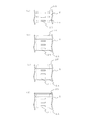
- FIG. 6 is a diagram illustrating pre-processing of the corrugated fin according to the first embodiment.
- the heat exchanger 10 of the first embodiment has a notch 2A in the corrugated fin 2. Therefore, a preliminary process is performed to form a notch 2A in the plate material.
- a preliminary process is performed to form a notch 2A in the plate material.
- the pre-processing not only the notch 2A can be formed, but also various processing can be performed according to the notch 2A.
- FIG. 6A shows a plate material that has been pre-processed to form a through hole 2D together with the notch 2A.
- FIG. 6B is a pre-processed plate material in which a notch 2A and a notch groove 2E having a thickness of about half of the plate thickness are formed in the plate thickness direction.
- FIG. 6C shows a plate material that has been pre-processed by bending the plate material together with the notch 2A to form a bent portion 2F having a bent habit.
- FIG. 6D shows a plate material that has been pre-processed with a plurality of dents 2G together with the notch 2A. In each case, the bending rigidity of the plate material can be further weakened together with the notch 2A.
- FIG. 6 four types of processing performed together with the formation of the notch 2A in the preliminary processing have been described, but other processing may be performed. Further, processing may be performed by combining the shapes of FIGS. 6 (a) to 6 (d).
- the bending rigidity in the portion having the notch 2A is different. Make it different from the part of.
- the portion having the notch 2A has a weak bending rigidity and is easily bent.
- the notch 2A of the corrugated fin 2 is formed by performing preliminary processing.
- the shape of the wave and the position of the notch such as the louver 2C and the position of the drainage hole 2B are performed by performing the preprocessing step together with the drilling step for forming the drainage hole 2B. It is possible to prevent the relationship from shifting.
- FIG. 7 is a diagram illustrating another example in the preprocessing of the corrugated fin according to the heat exchanger of the first embodiment.
- the corrugated fin 2 described above has the notch 2A so that the flexural rigidity of the portion having the notch 2A is different from that of the other portions.
- the flexural rigidity is made different by pre-processing other than forming the notch 2A.
- FIG. 7A is a plate material having the cut groove 2E described in FIG. 6 having different bending rigidity.
- FIG. 7B is a plate material having the bending rigidity portion 2F described in FIG. 6 having different bending rigidity.
- FIG. 7C is a plate material having the dents 2G described in FIG. 6 having different bending rigidity.
- the plate material to be the corrugated fin 2 shown in FIG. 7 has the effect of weakening the bending rigidity at a desired position regardless of the notch 2A. Therefore, it is not necessary to process the punched residue generated when the notch 2A is formed. Therefore, when the plate material is processed to manufacture the corrugated fin 2, the mold wear, failure, equipment malfunction, etc. due to the entrainment of the scraps are eliminated.
- FIG. 8 is a diagram illustrating another example in the preprocessing of the corrugated fin according to the heat exchanger of the first embodiment.
- the corrugated fin 2 of FIG. 8 has a bellows-shaped bent portion 2H in a wave shape formed along the bending direction by corrugating in a direction orthogonal to the top portion of the mountain portion.
- the bent portion 2H is formed in the mountain portion of the corrugated fin 2 at a position that is a belly portion other than the top portion, along the longitudinal direction of the plate material so as to be parallel to the drain hole 2B and the like. Therefore, the bent portion 2H is formed along the direction in which the wave shape is formed.
- the bending rigidity can be increased more than usual in the bending direction of the corrugated processing in which the plate material is processed into a wavy shape.
- the direction in which the plate material is bent is the direction in which the top portions of the mountain portions are continuous. Therefore, the difference in bending rigidity between the top portion where the bending rigidity is weakened by having the notch 2A and the portion having the bending portion 2H becomes large. Therefore, a portion having a weak bending rigidity and a portion having a strong bending rigidity are distinguished from each other, and the bending accuracy of bending a desired position in corrugated processing is further improved.
- the surface area of the portion where the bent portion 2H is formed becomes larger than that in the case where the bent portion 2H is not formed. Therefore, it is possible to increase the wind receiving area that receives the passing air in the abdominal portion of the mountain portion of the corrugated fin 2. Therefore, the bent portion 2H included in the corrugated fin 2 contributes to improving the performance of the heat exchanger not only during processing but also after processing.
- the bent portion 2H can be applied to the corrugated fin 2 having the above-mentioned cut groove 2E, bending portion 2F, dent 2G, or the like.
- the bent portion 2H can be formed together in the preliminary processing for forming the notch 2A, the notch groove 2E, the bent portion 2F, the dent 2G, and the like.
- FIG. 8 shows a corrugated fin 2 having a bent portion 2H together with a notch 2A, it may only have a bent portion 2H. In this case, punching residue is not generated by forming the notch 2A, and it is possible to prevent mold wear and breakage involving the punching residue. In addition, the rigidity and strength of the heat exchanger after brazing can be increased as compared with the preliminary processing at the bent position.
- Embodiment 2 the method of manufacturing the heat exchanger will be described focusing on the corrugated fin 2 in the first embodiment.
- a method of manufacturing the heat exchanger 10 having the corrugated fins 2 will be described.
- the multi-hole flat heat transfer tubes 1 and the corrugated fins 2 are alternately arranged to form a corrugated fin row in which the corrugated fins 2 are sandwiched between the multi-hole flat heat transfer tubes 1.
- a compression step is performed in which the multi-hole flat heat transfer tube 1 and the corrugated fin 2 are compressed in the direction in which they are arranged.
- the multi-hole flat heat transfer tube 1 and the top portion of the corrugated fin 2 are in close contact with each other, and the multi-hole flat heat transfer tube 1 and the top portion of the corrugated fin 2 are in surface contact with each other.
- the distance between the multi-hole flat heat transfer tubes 1 is kept constant, which matches the distance between the insertion holes (not shown) of the multi-hole flat heat transfer tube 1 of the header 3.
- the multi-hole flat heat transfer tube 1 is constrained to the insertion hole of the header 3 even if the compression is released. Therefore, the shape of the heat exchanger 10 is maintained even before the brazing step is performed.
- a corrugated fin row is formed through the above steps. After that, the multi-hole flat heat transfer tube 1, the corrugated fin 2, and the header 3 are brazed to manufacture the heat exchanger 10.
- FIG. 9 is a diagram illustrating a method for manufacturing a corrugated fin according to the second embodiment.
- the corrugated fin 2 is manufactured by performing a roller forming step.
- a notch processing for making a notch to be a louver 2C in the plate material and a corrugation processing for processing the plate material into a wavy shape are performed.
- the corrugated processing is performed using a gear-shaped roller mold 20 having mountain-shaped teeth.
- the roller forming step it is formed when the drilling step is performed unless the machining conditions such as unevenness of the plate thickness of the plate material, the machining tension, the machining speed, and the oil application state match at the optimum values.
- the drain hole 2B and the position in corrugated processing do not completely match.
- a part of the plate material has a weak bending rigidity and is a top portion in the corrugated shape of the corrugated fin 2.
- the positioning of the portion where the flexural rigidity is weak is performed more accurately. Therefore, as shown in FIG. 9B, in the second embodiment, the protrusion 21 used for positioning is installed on the mountain portion serving as the tooth of the roller mold 20.
- FIG. 10 is a diagram illustrating the teeth of the roller mold according to the second embodiment.
- the protrusion 21 is hooked on the notch 2A for weakening the rigidity described in the first embodiment to position the roller mold 20 and the plate material.
- a through hole 2D is formed together with the notch 2A, as shown in FIG. 10B, the protrusion 21 is hooked through the through hole 2D to form a roller mold 20 and a plate material to be a corrugated fin 2.
- Positioning may be performed.
- measures such as lowering the height of the protrusion 21 or increasing the gear diameter to reduce the angle at which the protrusion 21 passes through the through hole 2D are taken.
- the plate material is bent starting from the portion where the protrusion 21 is caught, and a mountain portion is formed.
- the height of the protrusion 21 is the plate thickness of the plate material + about 0.2 mm to 0.5 mm.
- the size of the protrusion 21 is about 0.01 mm to 0.2 mm smaller than the size of the notch 2A or the through hole 2D.
- FIG. 11 is a diagram illustrating the shape of the protrusion of the roller mold according to the second embodiment.
- FIG. 11A is a protrusion 21 with corners left.
- FIG. 11B is a protrusion 21 having a rounded corner with a chamfered corner or a rounded corner with a radius of 0.1 or more.
- 11 (c) and 11 (d) are protrusions 21 having different chamfered and rounded sizes at each corner, such as by chamfering one side of the tooth.
- FIG. 12 is a diagram for explaining the difference between the protrusion and the plate material according to the second embodiment.
- the tooth has corners as shown in FIG. 11A
- the corners interfere with the corners of the teeth, and the protrusions 21 become a plate material. It may not get caught well.
- the protrusion 21 may not come out of the plate material well. Therefore, in the second embodiment, as shown in the protrusion 21 shown in FIG. 11B, the corners of the teeth are chamfered to remove the corners. By removing the corners of the protrusions 21, as shown in FIG. 12B, the protrusions 21 can be smoothly hooked and pulled out during corrugation processing. Further, as shown in FIGS.
- the plate material to be the corrugated fin 2 can be easily removed. After the plate material is corrugated to produce the corrugated fin 2, the angle of the mountain portion and the size of the pitch are adjusted by compressing the corrugated fin 2 or the like.
- FIG. 13 is a diagram illustrating another example of manufacturing a corrugated fin according to the heat exchanger of the second embodiment.
- a plurality of notches 2A for weakening the bending rigidity were formed.
- the protrusions 21 to be installed on the mountain portion of the roller mold 20 are installed corresponding to the notches 2A.
- the notch 2A and the protrusion 21, which are portions having weak flexural rigidity are caught at two points in one wave, and the plate material is formed. Bending is done. Therefore, the corner of the mountain portion of the corrugated fin 2 can be processed into a sharper state.
- FIG. 14 is a diagram illustrating another example of positioning in corrugated processing according to the heat exchanger of the second embodiment.
- the drainage hole 2B formed in the drilling step may be used for positioning by passing the protrusion 21 through the drainage hole 2B.
- the distance between the through holes becomes extremely narrow, corrugating is performed without increasing or drilling the through hole 2D. It can be carried out.
- the notch 2A in the preliminary processing may be omitted.
- the contact area between the multi-hole flat heat transfer tube 1 and the top of the corrugated fin 2 is not reduced. Therefore, the brazing area can be increased and the heat exchange performance can be improved.
- the brazing material permeates into the space created by the notch 2A and the through hole 2D, so that the brazing material is insufficient and the brazing cut is less likely to occur. Therefore, the amount of brazing material used for production can be reduced. Therefore, the heat exchanger can be economically manufactured.
- roller mold 20 has a protrusion 21 on the top portion of the tooth, but the present invention is not limited to this.
- the same positioning effect can be obtained even if it is provided on the slope portion of the tooth.
- the protrusions 21 are provided on the teeth of the roller mold 20 to be corrugated, and the notch 2A formed by the preliminary processing is hooked or the through hole 2D is passed through. As a result, the plate material was positioned. Therefore, it is possible to manufacture the heat exchanger 10 having the corrugated fins 2 in which the drain holes 2B formed in the plate material in advance in the drilling step and the ridges are aligned with high accuracy.
- FIG. 15 is a diagram illustrating the position of the drain hole in the corrugated fin according to the third embodiment.
- a drainage hole 2B is provided in which the positions of the holes with respect to the corrugated processing direction are periodically shifted. Therefore, the positions of the drain holes 2B are different in the vertical direction of the corrugated fins 2.
- drain holes 2B arranged in a pseudo-random manner are provided in the corrugated fin 2 shown in FIG. 15B. Therefore, the positions of the drain holes 2B are different in the air passage direction.
- FIG. 16 is a diagram illustrating drainage of corrugated fins according to the third embodiment. Here, the discharge of condensed water in the corrugated fin 2 in which the drain hole 2B shown in FIG. 15B is formed will be described.
- the corrugated fins 2 at the three locations (1), (2) and (3) shown in FIG. 16 (a) are shown in FIG. 16 (b).
- the corrugated fins 2 at the three locations (1), (2) and (3) differ in the positions of the drain holes 2B in the vertical direction. Therefore, the corrugated fin 2 does not have a so-called atrium state due to the opening portion of the drain hole 2B, and there is a portion where the holes do not communicate in the vertical direction. Therefore, as shown in FIG. 16C, the condensed water flowing down from the upper fin falls on the lower fin and merges with the condensed water generated in the lower fin to increase the amount of water. It will be easier to flow down. Therefore, the drainage performance can be improved by having the corrugated fins 2 in which the positions of the drainage holes 2B are different as in the heat exchanger 10 of the third embodiment.
- Embodiment 4 a method of manufacturing the corrugated fin 2 by roller molding is shown as an example, but the molding method is not limited. For example, even when the corrugated fin 2 is manufactured by press working, positioning can be performed using the notch 2A and the through hole 2D shown in the second embodiment.
- the procedure of the drilling step of forming the drainage hole 2B of the corrugated fin 2 and the pre-processing for weakening the bending rigidity was not particularly mentioned.
- the preliminary processing may be performed at the same time. Further, the preliminary processing may be performed in a process different from the drilling process.
- the header 3 is inserted and brazed. It is not limited to this procedure.
- the header 3 may be attached after the multi-hole flat heat transfer tube 1 and the corrugated fin 2 are brazed. Further, not only the header 3 of the integrated component but also the header 3 can be divided to set the flow of the refrigerant in the heat exchanger 10.
- the multi-hole flat heat transfer tube 1 is shown as an example as the heat transfer tube, but this does not apply as long as it functions as a heat transfer tube.
- the internal partition wall 1B may not be provided and one flow path may be provided.
- the cross-sectional shape of the heat transfer tube is not particularly limited.
- the header 3 and the multi-hole flat heat transfer tube 1 have been described as being made of a metal containing aluminum, but the present invention is not limited to this.
- the materials of the header 3 and the multi-hole flat heat transfer tube 1 can be selected according to the purpose of use of the heat exchanger 10, the environment of the installation location, the properties of the heat exchange medium, and the like.
- the type of brazing material is not limited. As the brazing material, a type that is compatible with the materials of the header 3 and the multi-hole flat heat transfer tube 1 may be selected.
- the specific shape and structure, material and processing method of the corrugated fin 2 shown in the first and second embodiments are examples, and are not limited thereto.
- the shapes of the notch 2A and the through hole 2D formed by the pre-processing for positioning are not limited to those exemplified.
- the specific shapes, structures, materials, and processing methods of the multi-hole flat heat transfer tube 1 and the header 3 shown in the first embodiment are examples.
- the number and shape of the internal partition walls 1B included in the multi-hole flat heat transfer tube 1 are not limited to those exemplified.
- the specific shape and structure of the heat exchanger 10 shown in the first embodiment, the posture when mounted on the device, and the like are examples.
- the use of the heat exchanger 10 shown in the first embodiment is not particularly limited.
- the heat exchanger 10 may be used as an evaporator or condenser. Further, the heat exchanger 10 may be used as a cooler or a heater.
- the posture of the heat exchanger 10 shown in the second embodiment at the time of brazing and the orientation in which the heat exchanger 10 is actually installed are not particularly limited.
- a surface that was facing up at the time of brazing may be turned downward at the time of installation, or may be turned horizontally or vertically.
- FIG. 17 is a diagram showing a configuration of an air conditioner according to the fifth embodiment.
- an air conditioner will be described as an example of the refrigeration cycle device.
- the heat exchanger 10 described in the first to fourth embodiments is used as the outdoor heat exchanger 230.
- a refrigerant circuit is configured by connecting the outdoor unit 200 and the indoor unit 100 with a gas refrigerant pipe 300 and a liquid refrigerant pipe 400.
- the outdoor unit 200 includes a compressor 210, a four-way valve 220, and an outdoor heat exchanger 230.
- the compressor 210 compresses the sucked refrigerant and discharges it.
- the compressor 210 can change the capacity of the compressor 210 by arbitrarily changing the operating frequency by, for example, an inverter circuit or the like.
- the four-way valve 220 is a valve that switches the flow of the refrigerant depending on, for example, the cooling operation and the heating operation.
- the outdoor heat exchanger 230 exchanges heat between the refrigerant and the outdoor air. For example, it functions as an evaporator during heating operation to evaporate and vaporize the refrigerant. In addition, it functions as a condenser during cooling operation to condense and liquefy the refrigerant.
- the indoor heat exchanger 110 exchanges heat between, for example, the air in the room to be air-conditioned and the refrigerant. During heating operation, it functions as a condenser to condense and liquefy the refrigerant. In addition, it functions as an evaporator during cooling operation to evaporate and vaporize the refrigerant.
- the indoor unit 100 has an indoor heat exchanger 110, an expansion valve 120, and an indoor fan 130.
- the expansion valve 120 of the throttle device or the like decompresses the refrigerant and expands it.
- the opening degree is adjusted based on an instruction from a control device (not shown) or the like.
- the indoor heat exchanger 110 exchanges heat between the air in the room, which is the space subject to air conditioning, and the refrigerant.
- the indoor fan 130 passes the indoor air through the indoor heat exchanger 110, and supplies the air that has passed through the indoor heat exchanger 110 into the room.
- the heat exchanger 10 described in the first to fourth embodiments is used as the outdoor heat exchanger 230.
- the outdoor heat exchanger 230 with high processing accuracy can improve the heat exchange performance and improve the operating efficiency of the air conditioner.
- 1 Multi-hole flat heat transfer tube 1A outer tube, 1B internal partition, 2 corrugated fin, 2A notch, 2B drain hole, 2C louver, 2D through hole, 2E notch groove, 2F bending part, 2G dent, 2H bending part , 3, 3A, 3B header, 10 heat exchanger, 20 roller mold, 21 protrusion, 100 indoor unit, 110 indoor heat exchanger, 120 expansion valve, 130 indoor fan, 200 outdoor unit, 210 compressor, 220 four-way valve , 230 outdoor heat exchanger, 300 gas refrigerant piping, 400 liquid refrigerant piping.
Landscapes
- Engineering & Computer Science (AREA)
- Mechanical Engineering (AREA)
- Physics & Mathematics (AREA)
- Thermal Sciences (AREA)
- General Engineering & Computer Science (AREA)
- Geometry (AREA)
- Heat-Exchange Devices With Radiators And Conduit Assemblies (AREA)
Abstract
Cet échangeur de chaleur comprend : une pluralité de tubes de transfert de chaleur plans qui ont des formes respectives de section transversale plane, sont agencés de telle sorte que les surfaces externes planes s'opposent l'une à l'autre, et servent de trajets d'écoulement respectifs pour un fluide s'écoulant à l'intérieur des tubes ; et une pluralité d'ailettes ondulées dont chacune a une forme ondulée, est disposée entre des tubes de transfert de chaleur plans opposés, et est reliée aux tubes de transfert de chaleur plans, les sommets de la forme ondulée des ailettes ondulées ayant une rigidité à la flexion inférieure à celle des autres parties de celle-ci.
Priority Applications (2)
| Application Number | Priority Date | Filing Date | Title |
|---|---|---|---|
| US17/761,316 US20220341682A1 (en) | 2019-11-11 | 2020-10-29 | Heat exchanger, refrigeration cycle apparatus, method of manufacturing corrugated fin, and manufacturing apparatus for manufacturing corrugated fin |
| JP2021556001A JP7191247B2 (ja) | 2019-11-11 | 2020-10-29 | 熱交換器、冷凍サイクル装置およびコルゲートフィンの製造装置並びにコルゲートフィンの製造方法 |
Applications Claiming Priority (2)
| Application Number | Priority Date | Filing Date | Title |
|---|---|---|---|
| JP2019-203800 | 2019-11-11 | ||
| JP2019203800 | 2019-11-11 |
Publications (1)
| Publication Number | Publication Date |
|---|---|
| WO2021095538A1 true WO2021095538A1 (fr) | 2021-05-20 |
Family
ID=75912010
Family Applications (1)
| Application Number | Title | Priority Date | Filing Date |
|---|---|---|---|
| PCT/JP2020/040573 WO2021095538A1 (fr) | 2019-11-11 | 2020-10-29 | Échangeur de chaleur, dispositif à cycle frigorifique et procédé de fabrication d'ailette ondulée |
Country Status (3)
| Country | Link |
|---|---|
| US (1) | US20220341682A1 (fr) |
| JP (1) | JP7191247B2 (fr) |
| WO (1) | WO2021095538A1 (fr) |
Cited By (1)
| Publication number | Priority date | Publication date | Assignee | Title |
|---|---|---|---|---|
| WO2023203640A1 (fr) * | 2022-04-19 | 2023-10-26 | 三菱電機株式会社 | Échangeur de chaleur et climatiseur |
Citations (7)
| Publication number | Priority date | Publication date | Assignee | Title |
|---|---|---|---|---|
| JPS5666688U (fr) * | 1979-10-22 | 1981-06-03 | ||
| JPH05106986A (ja) * | 1991-10-14 | 1993-04-27 | Nippondenso Co Ltd | 熱交換器 |
| JPH11148793A (ja) * | 1997-11-14 | 1999-06-02 | Zexel:Kk | 一体型熱交換器に用いられるフィンの成形方法及び成形装置 |
| JP2001050678A (ja) * | 1999-08-09 | 2001-02-23 | Tokyo Radiator Mfg Co Ltd | 熱交換器 |
| JP2013139041A (ja) * | 2011-12-28 | 2013-07-18 | Daikin Industries Ltd | コルゲートフィンの製造方法 |
| JP2014114979A (ja) * | 2012-12-07 | 2014-06-26 | Keihin Thermal Technology Corp | ヒートポンプ式冷凍サイクル用室外熱交換器 |
| WO2014207785A1 (fr) * | 2013-06-28 | 2014-12-31 | 三菱重工業株式会社 | Échangeur de chaleur, structure d'échangeur de chaleur, et ailette destinée à un échangeur de chaleur |
Family Cites Families (2)
| Publication number | Priority date | Publication date | Assignee | Title |
|---|---|---|---|---|
| JP5106986B2 (ja) | 2007-10-29 | 2012-12-26 | 旭化成イーマテリアルズ株式会社 | 光ファイバセンサー |
| WO2012124037A1 (fr) | 2011-03-14 | 2012-09-20 | 特定非営利活動法人プロサップ | Appareil de chauffage d'agrégat et procédé de chauffage d'agrégat |
-
2020
- 2020-10-29 JP JP2021556001A patent/JP7191247B2/ja active Active
- 2020-10-29 WO PCT/JP2020/040573 patent/WO2021095538A1/fr active Application Filing
- 2020-10-29 US US17/761,316 patent/US20220341682A1/en active Pending
Patent Citations (7)
| Publication number | Priority date | Publication date | Assignee | Title |
|---|---|---|---|---|
| JPS5666688U (fr) * | 1979-10-22 | 1981-06-03 | ||
| JPH05106986A (ja) * | 1991-10-14 | 1993-04-27 | Nippondenso Co Ltd | 熱交換器 |
| JPH11148793A (ja) * | 1997-11-14 | 1999-06-02 | Zexel:Kk | 一体型熱交換器に用いられるフィンの成形方法及び成形装置 |
| JP2001050678A (ja) * | 1999-08-09 | 2001-02-23 | Tokyo Radiator Mfg Co Ltd | 熱交換器 |
| JP2013139041A (ja) * | 2011-12-28 | 2013-07-18 | Daikin Industries Ltd | コルゲートフィンの製造方法 |
| JP2014114979A (ja) * | 2012-12-07 | 2014-06-26 | Keihin Thermal Technology Corp | ヒートポンプ式冷凍サイクル用室外熱交換器 |
| WO2014207785A1 (fr) * | 2013-06-28 | 2014-12-31 | 三菱重工業株式会社 | Échangeur de chaleur, structure d'échangeur de chaleur, et ailette destinée à un échangeur de chaleur |
Cited By (1)
| Publication number | Priority date | Publication date | Assignee | Title |
|---|---|---|---|---|
| WO2023203640A1 (fr) * | 2022-04-19 | 2023-10-26 | 三菱電機株式会社 | Échangeur de chaleur et climatiseur |
Also Published As
| Publication number | Publication date |
|---|---|
| US20220341682A1 (en) | 2022-10-27 |
| JPWO2021095538A1 (fr) | 2021-05-20 |
| JP7191247B2 (ja) | 2022-12-16 |
Similar Documents
| Publication | Publication Date | Title |
|---|---|---|
| US9322602B2 (en) | Heat exchanger having a plurality of plate-like fins and a plurality of flat-shaped heat transfer pipes orthogonal to the plate-like fins | |
| JP5661202B2 (ja) | プレートフィンチューブ式熱交換器及びそれを備えた冷凍空調システム | |
| EP2863159B1 (fr) | Echangeur de chaleur, méthode de production de celui-ci et dispositif à cycle de réfrigération | |
| EP2667134A1 (fr) | Échangeur de chaleur et climatiseur | |
| US20120031601A1 (en) | Multichannel tubes with deformable webs | |
| JP6573722B2 (ja) | 熱交換器およびこの熱交換器を備えた冷凍サイクル装置 | |
| JP6734002B1 (ja) | 熱交換器および冷凍サイクル装置 | |
| JP2010078289A (ja) | 熱交換器及びこの熱交換器を備えた空気調和機 | |
| JP6765528B2 (ja) | 熱交換器、冷凍サイクル装置および空気調和機 | |
| WO2021095538A1 (fr) | Échangeur de chaleur, dispositif à cycle frigorifique et procédé de fabrication d'ailette ondulée | |
| WO2018056209A1 (fr) | Échangeur de chaleur | |
| JP6719657B2 (ja) | 熱交換器および冷凍サイクル装置 | |
| WO2020012549A1 (fr) | Échangeur de chaleur, dispositif d'échange de chaleur, unité d'échangeur de chaleur et système de réfrigération | |
| JP2009293849A (ja) | 熱交換器、及びこの熱交換器を用いた空気調和機 | |
| WO2017208419A1 (fr) | Échangeur de chaleur de type à tubes et ailettes, appareil de type pompe à chaleur équipé de l'échangeur de chaleur de type à tubes et ailettes et procédé de fabrication de l'échangeur de chaleur de type à tubes et ailettes | |
| WO2013094084A1 (fr) | Climatiseur | |
| JP2019158215A (ja) | 空気調和機及び熱交換器 | |
| WO2021234961A1 (fr) | Échangeur de chaleur, unité extérieure de dispositif de climatisation, et dispositif de climatisation | |
| JP5664272B2 (ja) | 熱交換器及び空気調和機 | |
| WO2023199400A1 (fr) | Échangeur de chaleur et dispositif à cycle de réfrigération | |
| WO2021205905A1 (fr) | Échangeur de chaleur, climatiseur et procédé de fabrication d'un échangeur de chaleur | |
| WO2023203640A1 (fr) | Échangeur de chaleur et climatiseur | |
| WO2021245734A1 (fr) | Échangeur de chaleur et appareil à cycle de réfrigération | |
| KR100517925B1 (ko) | 핀-튜브 일체형 열교환기 | |
| US20220373264A1 (en) | Heat exchanger, heat exchanger unit, and refrigeration cycle apparatus |
Legal Events
| Date | Code | Title | Description |
|---|---|---|---|
| 121 | Ep: the epo has been informed by wipo that ep was designated in this application |
Ref document number: 20888332 Country of ref document: EP Kind code of ref document: A1 |
|
| ENP | Entry into the national phase |
Ref document number: 2021556001 Country of ref document: JP Kind code of ref document: A |
|
| NENP | Non-entry into the national phase |
Ref country code: DE |
|
| 122 | Ep: pct application non-entry in european phase |
Ref document number: 20888332 Country of ref document: EP Kind code of ref document: A1 |