WO2021095538A1 - 熱交換器および冷凍サイクル装置並びにコルゲートフィンの製造方法 - Google Patents
熱交換器および冷凍サイクル装置並びにコルゲートフィンの製造方法 Download PDFInfo
- Publication number
- WO2021095538A1 WO2021095538A1 PCT/JP2020/040573 JP2020040573W WO2021095538A1 WO 2021095538 A1 WO2021095538 A1 WO 2021095538A1 JP 2020040573 W JP2020040573 W JP 2020040573W WO 2021095538 A1 WO2021095538 A1 WO 2021095538A1
- Authority
- WO
- WIPO (PCT)
- Prior art keywords
- corrugated fin
- heat exchanger
- corrugated
- heat transfer
- notch
- Prior art date
Links
Images


Classifications
-
- F—MECHANICAL ENGINEERING; LIGHTING; HEATING; WEAPONS; BLASTING
- F28—HEAT EXCHANGE IN GENERAL
- F28F—DETAILS OF HEAT-EXCHANGE AND HEAT-TRANSFER APPARATUS, OF GENERAL APPLICATION
- F28F1/00—Tubular elements; Assemblies of tubular elements
- F28F1/10—Tubular elements and assemblies thereof with means for increasing heat-transfer area, e.g. with fins, with projections, with recesses
- F28F1/12—Tubular elements and assemblies thereof with means for increasing heat-transfer area, e.g. with fins, with projections, with recesses the means being only outside the tubular element
- F28F1/24—Tubular elements and assemblies thereof with means for increasing heat-transfer area, e.g. with fins, with projections, with recesses the means being only outside the tubular element and extending transversely
- F28F1/30—Tubular elements and assemblies thereof with means for increasing heat-transfer area, e.g. with fins, with projections, with recesses the means being only outside the tubular element and extending transversely the means being attachable to the element
-
- B—PERFORMING OPERATIONS; TRANSPORTING
- B21—MECHANICAL METAL-WORKING WITHOUT ESSENTIALLY REMOVING MATERIAL; PUNCHING METAL
- B21D—WORKING OR PROCESSING OF SHEET METAL OR METAL TUBES, RODS OR PROFILES WITHOUT ESSENTIALLY REMOVING MATERIAL; PUNCHING METAL
- B21D13/00—Corrugating sheet metal, rods or profiles; Bending sheet metal, rods or profiles into wave form
- B21D13/04—Corrugating sheet metal, rods or profiles; Bending sheet metal, rods or profiles into wave form by rolling
-
- B—PERFORMING OPERATIONS; TRANSPORTING
- B21—MECHANICAL METAL-WORKING WITHOUT ESSENTIALLY REMOVING MATERIAL; PUNCHING METAL
- B21D—WORKING OR PROCESSING OF SHEET METAL OR METAL TUBES, RODS OR PROFILES WITHOUT ESSENTIALLY REMOVING MATERIAL; PUNCHING METAL
- B21D11/00—Bending not restricted to forms of material mentioned in only one of groups B21D5/00, B21D7/00, B21D9/00; Bending not provided for in groups B21D5/00 - B21D9/00; Twisting
- B21D11/08—Bending by altering the thickness of part of the cross-section of the work
-
- B—PERFORMING OPERATIONS; TRANSPORTING
- B21—MECHANICAL METAL-WORKING WITHOUT ESSENTIALLY REMOVING MATERIAL; PUNCHING METAL
- B21D—WORKING OR PROCESSING OF SHEET METAL OR METAL TUBES, RODS OR PROFILES WITHOUT ESSENTIALLY REMOVING MATERIAL; PUNCHING METAL
- B21D53/00—Making other particular articles
- B21D53/02—Making other particular articles heat exchangers or parts thereof, e.g. radiators, condensers fins, headers
- B21D53/022—Making the fins
-
- F—MECHANICAL ENGINEERING; LIGHTING; HEATING; WEAPONS; BLASTING
- F28—HEAT EXCHANGE IN GENERAL
- F28F—DETAILS OF HEAT-EXCHANGE AND HEAT-TRANSFER APPARATUS, OF GENERAL APPLICATION
- F28F1/00—Tubular elements; Assemblies of tubular elements
- F28F1/02—Tubular elements of cross-section which is non-circular
-
- F—MECHANICAL ENGINEERING; LIGHTING; HEATING; WEAPONS; BLASTING
- F28—HEAT EXCHANGE IN GENERAL
- F28F—DETAILS OF HEAT-EXCHANGE AND HEAT-TRANSFER APPARATUS, OF GENERAL APPLICATION
- F28F1/00—Tubular elements; Assemblies of tubular elements
- F28F1/10—Tubular elements and assemblies thereof with means for increasing heat-transfer area, e.g. with fins, with projections, with recesses
- F28F1/12—Tubular elements and assemblies thereof with means for increasing heat-transfer area, e.g. with fins, with projections, with recesses the means being only outside the tubular element
- F28F1/126—Tubular elements and assemblies thereof with means for increasing heat-transfer area, e.g. with fins, with projections, with recesses the means being only outside the tubular element consisting of zig-zag shaped fins
- F28F1/128—Fins with openings, e.g. louvered fins
-
- F—MECHANICAL ENGINEERING; LIGHTING; HEATING; WEAPONS; BLASTING
- F28—HEAT EXCHANGE IN GENERAL
- F28F—DETAILS OF HEAT-EXCHANGE AND HEAT-TRANSFER APPARATUS, OF GENERAL APPLICATION
- F28F17/00—Removing ice or water from heat-exchange apparatus
- F28F17/005—Means for draining condensates from heat exchangers, e.g. from evaporators
-
- F—MECHANICAL ENGINEERING; LIGHTING; HEATING; WEAPONS; BLASTING
- F28—HEAT EXCHANGE IN GENERAL
- F28D—HEAT-EXCHANGE APPARATUS, NOT PROVIDED FOR IN ANOTHER SUBCLASS, IN WHICH THE HEAT-EXCHANGE MEDIA DO NOT COME INTO DIRECT CONTACT
- F28D1/00—Heat-exchange apparatus having stationary conduit assemblies for one heat-exchange medium only, the media being in contact with different sides of the conduit wall, in which the other heat-exchange medium is a large body of fluid, e.g. domestic or motor car radiators
- F28D1/02—Heat-exchange apparatus having stationary conduit assemblies for one heat-exchange medium only, the media being in contact with different sides of the conduit wall, in which the other heat-exchange medium is a large body of fluid, e.g. domestic or motor car radiators with heat-exchange conduits immersed in the body of fluid
- F28D1/04—Heat-exchange apparatus having stationary conduit assemblies for one heat-exchange medium only, the media being in contact with different sides of the conduit wall, in which the other heat-exchange medium is a large body of fluid, e.g. domestic or motor car radiators with heat-exchange conduits immersed in the body of fluid with tubular conduits
- F28D1/053—Heat-exchange apparatus having stationary conduit assemblies for one heat-exchange medium only, the media being in contact with different sides of the conduit wall, in which the other heat-exchange medium is a large body of fluid, e.g. domestic or motor car radiators with heat-exchange conduits immersed in the body of fluid with tubular conduits the conduits being straight
- F28D1/0535—Heat-exchange apparatus having stationary conduit assemblies for one heat-exchange medium only, the media being in contact with different sides of the conduit wall, in which the other heat-exchange medium is a large body of fluid, e.g. domestic or motor car radiators with heat-exchange conduits immersed in the body of fluid with tubular conduits the conduits being straight the conduits having a non-circular cross-section
- F28D1/05366—Assemblies of conduits connected to common headers, e.g. core type radiators
-
- F—MECHANICAL ENGINEERING; LIGHTING; HEATING; WEAPONS; BLASTING
- F28—HEAT EXCHANGE IN GENERAL
- F28F—DETAILS OF HEAT-EXCHANGE AND HEAT-TRANSFER APPARATUS, OF GENERAL APPLICATION
- F28F2215/00—Fins
- F28F2215/08—Fins with openings, e.g. louvers
-
- F—MECHANICAL ENGINEERING; LIGHTING; HEATING; WEAPONS; BLASTING
- F28—HEAT EXCHANGE IN GENERAL
- F28F—DETAILS OF HEAT-EXCHANGE AND HEAT-TRANSFER APPARATUS, OF GENERAL APPLICATION
- F28F2275/00—Fastening; Joining
- F28F2275/04—Fastening; Joining by brazing
- F28F2275/045—Fastening; Joining by brazing with particular processing steps, e.g. by allowing displacement of parts during brazing or by using a reservoir for storing brazing material
Definitions
- the present invention relates to a heat exchanger, a refrigeration cycle device, and a method for manufacturing corrugated fins. In particular, it relates to the processing accuracy of corrugated fins.
- the heat transfer tube through which the refrigerant flows has been changed from a circular tube to a multi-hole flat heat transfer tube for the purpose of saving refrigerant and improving performance. Exchanges are being developed.
- a roller forming step is performed as in Patent Document 1.
- a gear-shaped roller mold is used to perform corrugated processing for processing the plate material into a wavy shape and cutting processing for making a notch to be a louver or the like in the plate material.
- the plate material to be the corrugated fin is affected by the oil application state and the tension change due to bending in the corrugated processing. For this reason, there is a problem that the processing accuracy is lowered, such as different wave intervals.
- the wave shape formed in the roller forming process and the positional deviation between the notch and the drain hole may occur.
- An object of the present invention is to obtain a heat exchanger and a refrigeration cycle device having corrugated fins with high processing accuracy and a method for manufacturing corrugated fins in order to solve the above-mentioned problems.
- the heat exchanger according to the present invention has a plurality of flat heat transfer tubes having a flat cross section, the flat outer surfaces are arranged to face each other, and the inside of the tube serves as a flow path for fluid to flow, and waves.
- a heat exchanger having a shape, arranged between facing flat heat transfer tubes, and having a plurality of corrugated fins joined to the flat heat transfer tubes.
- the corrugated fin has a corrugated top portion at another portion. It has a weaker bending rigidity than that.
- the refrigeration cycle device has the above heat exchanger.
- the method for manufacturing corrugated fins according to the present invention is a method for manufacturing corrugated fins in a heat exchanger, and is a preliminary method for forming a portion having a flexural rigidity weaker than other portions with respect to a plate material to be a corrugated fin. It includes a step of performing processing and a step of performing corrugated processing in which a portion of the plate material having weak flexural rigidity is bent to form a wavy shape.
- the corrugated fins of the heat exchanger have parts having different bending rigidity.
- the corrugated top portion has a corrugated fin that has weak flexural rigidity and is easily bent. Therefore, it is possible to obtain a heat exchanger having corrugated fins having a wave shape with high accuracy such as wave spacing.
- FIG. It is a figure explaining the structure of the heat exchanger which concerns on Embodiment 1.
- FIG. It is a figure explaining the internal structure of the multi-hole flat heat transfer tube which concerns on Embodiment 1.
- FIG. It is a figure explaining the corrugated fin which concerns on the heat exchanger of Embodiment 1.
- FIG. It is a figure explaining another example of the corrugated fin which concerns on the heat exchanger of Embodiment 1.
- FIG. It is a figure which shows the example of the notch of the corrugated fin which concerns on Embodiment 1.
- FIG. It is a figure explaining the preliminary processing of the corrugated fin which concerns on Embodiment 1.
- FIG. It is a figure explaining another example in the preliminary processing of the corrugated fin which concerns on the heat exchanger of Embodiment 1.
- FIG. It is a figure explaining another example in the preliminary processing of the corrugated fin which concerns on the heat exchanger of Embodiment 1.
- FIG. It is a figure explaining the manufacturing method of the corrugated fin which concerns on Embodiment 2.
- FIG. It is a figure explaining the tooth of the roller mold which concerns on Embodiment 2.
- FIG. It is a figure explaining the shape of the protrusion of the roller mold which concerns on Embodiment 2.
- FIG. It is a figure explaining the difference between the protrusion and the plate material which concerns on Embodiment 2.
- FIG. It is a figure explaining another example of manufacturing of the corrugated fin which concerns on the heat exchanger of Embodiment 2.
- FIG. It is a figure explaining another example of positioning in corrugated processing which concerns on the heat exchanger of Embodiment 2.
- FIG. It is a figure explaining the position of the drainage hole in the corrugated fin which concerns on Embodiment 3.
- FIG. It is a figure explaining the drainage of the corrugated fin which concerns on Embodiment 3.
- FIG. It is a figure which shows the structure of the air conditioner which concerns on Embodiment 5.
- FIG. 1 is a diagram illustrating a configuration of a heat exchanger according to the first embodiment.
- the heat exchanger 10 of the first embodiment is a corrugated fin tube type heat exchanger having a parallel piping type.
- the heat exchanger 10 has a plurality of multi-hole flat heat transfer tubes 1, a plurality of corrugated fins 2, and a pair of headers 3 (header 3A and header 3B).
- Each header 3 is a pipe that is connected to an external device by piping, and a refrigerant that is a fluid serving as a heat exchange medium flows in and out, and the refrigerant branches or merges.
- a plurality of multi-hole flat heat transfer tubes 1 are arranged in parallel between the two headers 3 so as to be perpendicular to each header 3.
- the two headers 3 are arranged separately in the vertical direction, and the header 3A through which the liquid refrigerant passes is provided.
- the header 3B which is on the lower side and through which the gaseous refrigerant passes, is located on the upper side.
- the multi-hole flat heat transfer tube 1 has a flat cross section, and the outer surface on the longitudinal side of the flat shape which is the air flow direction is flat and orthogonal to the longitudinal direction. It is a flat heat transfer tube whose outer surface on the short side is curved.
- the multi-hole flat heat transfer tube 1 has a plurality of holes that serve as a flow path for the refrigerant inside the tube. In the first embodiment, the holes of the multi-hole flat heat transfer tube 1 are oriented in the vertical direction because they serve as a flow path between the headers 3.
- the multi-hole flat heat transfer tubes 1 are arranged at equal intervals in the horizontal direction with their outer surfaces facing each other on the longitudinal side. As will be described later, each multi-hole flat heat transfer tube 1 is brazed and joined with each header 3 by a brazing material. The multi-hole flat heat transfer tube 1 will be described in detail later.
- the heat exchanger 10 when used as a condenser, high-temperature and high-pressure refrigerant flows through the refrigerant flow path in the multi-hole flat heat transfer tube 1.
- the heat exchanger 10 When the heat exchanger 10 is used as an evaporator, low-temperature and low-pressure refrigerant flows through the refrigerant flow path in the multi-hole flat heat transfer tube 1.
- the refrigerant flows into one of the headers 3 from an external device (not shown) through a pipe (not shown) that supplies the refrigerant to the heat exchanger 10.
- the refrigerant that has flowed into one of the headers 3 is distributed and passes through each of the multi-hole flat heat transfer tubes 1.
- the multi-hole flat heat transfer tube 1 exchanges heat between the refrigerant passing through the tube and the outside air, which is the outside atmosphere passing outside the tube. At this time, the refrigerant dissipates heat to the atmosphere or absorbs heat from the atmosphere while passing through the multi-hole flat heat transfer tube 1. When the temperature of the refrigerant is higher than the temperature of the outside air, the refrigerant releases its own heat to the outside air. When the temperature of the refrigerant is lower than the temperature of the outside air, the refrigerant absorbs heat from the atmosphere. The refrigerant that has passed through the multi-hole flat heat transfer tube 1 and exchanged heat flows into the other header 3 and merges. Then, the refrigerant is returned to an external device (not shown) through a pipe (not shown) connected to the other header 3.
- corrugated fins 2 are arranged between the arranged multi-hole flat heat transfer tubes 1.
- the corrugated fins 2 are fins arranged to increase the heat transfer area between the refrigerant and the outside air.
- the corrugated fin 2 is formed in a wavy shape as a bellows by a zigzag fold that repeats mountain folds and valley folds with respect to the plate-shaped member.
- the unevenness formed in a wavy shape becomes a mountain portion.
- the mountain portions of the corrugated fins 2 are arranged in the vertical direction.
- the flat surface of the multi-hole flat heat transfer tube 1 and the corrugated fin 2 have surface contact with the top portion of the mountain portion, and the contact portion is brazed and joined by a brazing material.
- the corrugated fin 2 will be described in detail later.
- FIG. 2 is a diagram for explaining the internal configuration of the multi-hole flat heat transfer tube according to the first embodiment.
- the multi-hole flat heat transfer tube 1 is, for example, a tube material formed by extruding an aluminum alloy.
- the multi-hole flat heat transfer tube 1 has a flat outer tube 1A and an internal partition wall 1B that partitions the inside of the outer tube and divides the inside into two or more flow paths.
- the outer pipe 1A and the inner partition wall 1B are made of the same material.
- the length of the outer tube 1A in the lateral direction is 1 mm to 5 mm.
- the length of the outer tube 1A in the longitudinal direction is 10 mm to 40 mm.
- the outer pipe 1A and the inner partition wall 1B each have a thickness of 0.2 mm or more from the viewpoint of pressure resistance and corrosion resistance. Further, the plate thickness of the outer pipe 1A and the inner partition wall 1B and the inner partition wall 1B are the same in all parts.
- the multi-hole flat heat transfer tube 1 is inserted into an insertion hole (not shown) included in the header 3 and brazed.
- the brazing brazing material for example, a brazing material containing aluminum is used.
- the brazing method involves heating the brazing material with a burner, high-frequency induction heating, an electric furnace, or the like to perform brazing. As long as brazing can be performed, the heating method of the brazing material does not matter.
- the brazing material can be supplied by manual insertion or placing brazing.
- wire brazing, paste brazing, clad material, foil brazing, or the like can be used.
- the gap between the insertion hole of the header 3 and the multi-hole flat heat transfer tube 1 is such that the multi-hole flat heat transfer tube 1 can be easily inserted and brazing property must be maintained. Therefore, the gap is often about 0.1 mm to 0.4 mm.
- the plate material of the corrugated fin 2 is made of, for example, an aluminum alloy. Then, a brazing material layer is clad on the surface of the plate material.
- the clad brazing material layer is based on, for example, a brazing material containing aluminum-silicon-based aluminum.
- the plate thickness of the plate material is about 50 ⁇ m to 200 ⁇ m.
- the corrugated fin 2 has a drain hole 2B for draining the condensed water generated on the fin or the like.
- the shape of the drain hole 2B may be any shape, for example, a square or a rectangle. Further, it is desirable that the length of one side of the drain hole 2B is 0.7 mm or more.
- FIG. 3 is a diagram illustrating a corrugated fin according to the heat exchanger of the first embodiment.
- FIG. 3 shows the state of the plate material that has not been corrugated with respect to the corrugated fin 2.
- the corrugated fin 2 included in the heat exchanger 10 of the first embodiment has a notch 2A, a drain hole 2B, and a louver 2C.
- the louver 2C changes the flow of air through the fins.
- the louver 2C has a slit that serves as a through hole through which air passes, and a plate portion that guides air that passes through the slit.
- the louver 2C is formed by cutting up a plate portion by cutting.
- the drain hole 2B is a through hole for draining the condensed water on the fin.
- the corrugated fin 2 of the first embodiment has a notch 2A at a position which is a top portion of each mountain portion.
- the bending rigidity of a part of the plate material is weakened by providing the notch 2A at the position which becomes the top portion of the wavy shape.
- a portion having a weak flexural rigidity becomes a bent portion that is easily bent, and serves as a reference for positioning each top portion when performing mountain folds and valley folds. Therefore, when the corrugated fin 2 of the first embodiment is manufactured, the plate material is preprocessed to form a notch 2A in the plate material, and a portion having a weak flexural rigidity is intentionally created.
- FIG. 4 is a diagram illustrating another example of the corrugated fin according to the heat exchanger of the first embodiment. For example, as shown in FIG. 4, even in the corrugated fin 2 having two notches 2A and formed so that the position of the top of the mountain portion is flat, a portion having a weak flexural rigidity is intentionally created. And the same effect can be obtained.
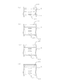
- FIG. 5 is a diagram showing an example of a notch of the corrugated fin according to the first embodiment.
- FIG. 5A shows a rectangular notch 2A.
- FIG. 5B shows a semicircular notch 2A.
- FIG. 5C shows a triangular notch 2A.
- FIG. 5D shows a plurality of notches 2A formed.
- four types of notches 2A have been described, but the shape or number of the notches 2A does not matter as long as the structure weakens the rigidity of the bent portion.
- the shape of the notch 2A or the like may be a shape in consideration of drainage performance and heat transfer performance.
- FIG. 6 is a diagram illustrating pre-processing of the corrugated fin according to the first embodiment.
- the heat exchanger 10 of the first embodiment has a notch 2A in the corrugated fin 2. Therefore, a preliminary process is performed to form a notch 2A in the plate material.
- a preliminary process is performed to form a notch 2A in the plate material.
- the pre-processing not only the notch 2A can be formed, but also various processing can be performed according to the notch 2A.
- FIG. 6A shows a plate material that has been pre-processed to form a through hole 2D together with the notch 2A.
- FIG. 6B is a pre-processed plate material in which a notch 2A and a notch groove 2E having a thickness of about half of the plate thickness are formed in the plate thickness direction.
- FIG. 6C shows a plate material that has been pre-processed by bending the plate material together with the notch 2A to form a bent portion 2F having a bent habit.
- FIG. 6D shows a plate material that has been pre-processed with a plurality of dents 2G together with the notch 2A. In each case, the bending rigidity of the plate material can be further weakened together with the notch 2A.
- FIG. 6 four types of processing performed together with the formation of the notch 2A in the preliminary processing have been described, but other processing may be performed. Further, processing may be performed by combining the shapes of FIGS. 6 (a) to 6 (d).
- the bending rigidity in the portion having the notch 2A is different. Make it different from the part of.
- the portion having the notch 2A has a weak bending rigidity and is easily bent.
- the notch 2A of the corrugated fin 2 is formed by performing preliminary processing.
- the shape of the wave and the position of the notch such as the louver 2C and the position of the drainage hole 2B are performed by performing the preprocessing step together with the drilling step for forming the drainage hole 2B. It is possible to prevent the relationship from shifting.
- FIG. 7 is a diagram illustrating another example in the preprocessing of the corrugated fin according to the heat exchanger of the first embodiment.
- the corrugated fin 2 described above has the notch 2A so that the flexural rigidity of the portion having the notch 2A is different from that of the other portions.
- the flexural rigidity is made different by pre-processing other than forming the notch 2A.
- FIG. 7A is a plate material having the cut groove 2E described in FIG. 6 having different bending rigidity.
- FIG. 7B is a plate material having the bending rigidity portion 2F described in FIG. 6 having different bending rigidity.
- FIG. 7C is a plate material having the dents 2G described in FIG. 6 having different bending rigidity.
- the plate material to be the corrugated fin 2 shown in FIG. 7 has the effect of weakening the bending rigidity at a desired position regardless of the notch 2A. Therefore, it is not necessary to process the punched residue generated when the notch 2A is formed. Therefore, when the plate material is processed to manufacture the corrugated fin 2, the mold wear, failure, equipment malfunction, etc. due to the entrainment of the scraps are eliminated.
- FIG. 8 is a diagram illustrating another example in the preprocessing of the corrugated fin according to the heat exchanger of the first embodiment.
- the corrugated fin 2 of FIG. 8 has a bellows-shaped bent portion 2H in a wave shape formed along the bending direction by corrugating in a direction orthogonal to the top portion of the mountain portion.
- the bent portion 2H is formed in the mountain portion of the corrugated fin 2 at a position that is a belly portion other than the top portion, along the longitudinal direction of the plate material so as to be parallel to the drain hole 2B and the like. Therefore, the bent portion 2H is formed along the direction in which the wave shape is formed.
- the bending rigidity can be increased more than usual in the bending direction of the corrugated processing in which the plate material is processed into a wavy shape.
- the direction in which the plate material is bent is the direction in which the top portions of the mountain portions are continuous. Therefore, the difference in bending rigidity between the top portion where the bending rigidity is weakened by having the notch 2A and the portion having the bending portion 2H becomes large. Therefore, a portion having a weak bending rigidity and a portion having a strong bending rigidity are distinguished from each other, and the bending accuracy of bending a desired position in corrugated processing is further improved.
- the surface area of the portion where the bent portion 2H is formed becomes larger than that in the case where the bent portion 2H is not formed. Therefore, it is possible to increase the wind receiving area that receives the passing air in the abdominal portion of the mountain portion of the corrugated fin 2. Therefore, the bent portion 2H included in the corrugated fin 2 contributes to improving the performance of the heat exchanger not only during processing but also after processing.
- the bent portion 2H can be applied to the corrugated fin 2 having the above-mentioned cut groove 2E, bending portion 2F, dent 2G, or the like.
- the bent portion 2H can be formed together in the preliminary processing for forming the notch 2A, the notch groove 2E, the bent portion 2F, the dent 2G, and the like.
- FIG. 8 shows a corrugated fin 2 having a bent portion 2H together with a notch 2A, it may only have a bent portion 2H. In this case, punching residue is not generated by forming the notch 2A, and it is possible to prevent mold wear and breakage involving the punching residue. In addition, the rigidity and strength of the heat exchanger after brazing can be increased as compared with the preliminary processing at the bent position.
- Embodiment 2 the method of manufacturing the heat exchanger will be described focusing on the corrugated fin 2 in the first embodiment.
- a method of manufacturing the heat exchanger 10 having the corrugated fins 2 will be described.
- the multi-hole flat heat transfer tubes 1 and the corrugated fins 2 are alternately arranged to form a corrugated fin row in which the corrugated fins 2 are sandwiched between the multi-hole flat heat transfer tubes 1.
- a compression step is performed in which the multi-hole flat heat transfer tube 1 and the corrugated fin 2 are compressed in the direction in which they are arranged.
- the multi-hole flat heat transfer tube 1 and the top portion of the corrugated fin 2 are in close contact with each other, and the multi-hole flat heat transfer tube 1 and the top portion of the corrugated fin 2 are in surface contact with each other.
- the distance between the multi-hole flat heat transfer tubes 1 is kept constant, which matches the distance between the insertion holes (not shown) of the multi-hole flat heat transfer tube 1 of the header 3.
- the multi-hole flat heat transfer tube 1 is constrained to the insertion hole of the header 3 even if the compression is released. Therefore, the shape of the heat exchanger 10 is maintained even before the brazing step is performed.
- a corrugated fin row is formed through the above steps. After that, the multi-hole flat heat transfer tube 1, the corrugated fin 2, and the header 3 are brazed to manufacture the heat exchanger 10.
- FIG. 9 is a diagram illustrating a method for manufacturing a corrugated fin according to the second embodiment.
- the corrugated fin 2 is manufactured by performing a roller forming step.
- a notch processing for making a notch to be a louver 2C in the plate material and a corrugation processing for processing the plate material into a wavy shape are performed.
- the corrugated processing is performed using a gear-shaped roller mold 20 having mountain-shaped teeth.
- the roller forming step it is formed when the drilling step is performed unless the machining conditions such as unevenness of the plate thickness of the plate material, the machining tension, the machining speed, and the oil application state match at the optimum values.
- the drain hole 2B and the position in corrugated processing do not completely match.
- a part of the plate material has a weak bending rigidity and is a top portion in the corrugated shape of the corrugated fin 2.
- the positioning of the portion where the flexural rigidity is weak is performed more accurately. Therefore, as shown in FIG. 9B, in the second embodiment, the protrusion 21 used for positioning is installed on the mountain portion serving as the tooth of the roller mold 20.
- FIG. 10 is a diagram illustrating the teeth of the roller mold according to the second embodiment.
- the protrusion 21 is hooked on the notch 2A for weakening the rigidity described in the first embodiment to position the roller mold 20 and the plate material.
- a through hole 2D is formed together with the notch 2A, as shown in FIG. 10B, the protrusion 21 is hooked through the through hole 2D to form a roller mold 20 and a plate material to be a corrugated fin 2.
- Positioning may be performed.
- measures such as lowering the height of the protrusion 21 or increasing the gear diameter to reduce the angle at which the protrusion 21 passes through the through hole 2D are taken.
- the plate material is bent starting from the portion where the protrusion 21 is caught, and a mountain portion is formed.
- the height of the protrusion 21 is the plate thickness of the plate material + about 0.2 mm to 0.5 mm.
- the size of the protrusion 21 is about 0.01 mm to 0.2 mm smaller than the size of the notch 2A or the through hole 2D.
- FIG. 11 is a diagram illustrating the shape of the protrusion of the roller mold according to the second embodiment.
- FIG. 11A is a protrusion 21 with corners left.
- FIG. 11B is a protrusion 21 having a rounded corner with a chamfered corner or a rounded corner with a radius of 0.1 or more.
- 11 (c) and 11 (d) are protrusions 21 having different chamfered and rounded sizes at each corner, such as by chamfering one side of the tooth.
- FIG. 12 is a diagram for explaining the difference between the protrusion and the plate material according to the second embodiment.
- the tooth has corners as shown in FIG. 11A
- the corners interfere with the corners of the teeth, and the protrusions 21 become a plate material. It may not get caught well.
- the protrusion 21 may not come out of the plate material well. Therefore, in the second embodiment, as shown in the protrusion 21 shown in FIG. 11B, the corners of the teeth are chamfered to remove the corners. By removing the corners of the protrusions 21, as shown in FIG. 12B, the protrusions 21 can be smoothly hooked and pulled out during corrugation processing. Further, as shown in FIGS.
- the plate material to be the corrugated fin 2 can be easily removed. After the plate material is corrugated to produce the corrugated fin 2, the angle of the mountain portion and the size of the pitch are adjusted by compressing the corrugated fin 2 or the like.
- FIG. 13 is a diagram illustrating another example of manufacturing a corrugated fin according to the heat exchanger of the second embodiment.
- a plurality of notches 2A for weakening the bending rigidity were formed.
- the protrusions 21 to be installed on the mountain portion of the roller mold 20 are installed corresponding to the notches 2A.
- the notch 2A and the protrusion 21, which are portions having weak flexural rigidity are caught at two points in one wave, and the plate material is formed. Bending is done. Therefore, the corner of the mountain portion of the corrugated fin 2 can be processed into a sharper state.
- FIG. 14 is a diagram illustrating another example of positioning in corrugated processing according to the heat exchanger of the second embodiment.
- the drainage hole 2B formed in the drilling step may be used for positioning by passing the protrusion 21 through the drainage hole 2B.
- the distance between the through holes becomes extremely narrow, corrugating is performed without increasing or drilling the through hole 2D. It can be carried out.
- the notch 2A in the preliminary processing may be omitted.
- the contact area between the multi-hole flat heat transfer tube 1 and the top of the corrugated fin 2 is not reduced. Therefore, the brazing area can be increased and the heat exchange performance can be improved.
- the brazing material permeates into the space created by the notch 2A and the through hole 2D, so that the brazing material is insufficient and the brazing cut is less likely to occur. Therefore, the amount of brazing material used for production can be reduced. Therefore, the heat exchanger can be economically manufactured.
- roller mold 20 has a protrusion 21 on the top portion of the tooth, but the present invention is not limited to this.
- the same positioning effect can be obtained even if it is provided on the slope portion of the tooth.
- the protrusions 21 are provided on the teeth of the roller mold 20 to be corrugated, and the notch 2A formed by the preliminary processing is hooked or the through hole 2D is passed through. As a result, the plate material was positioned. Therefore, it is possible to manufacture the heat exchanger 10 having the corrugated fins 2 in which the drain holes 2B formed in the plate material in advance in the drilling step and the ridges are aligned with high accuracy.
- FIG. 15 is a diagram illustrating the position of the drain hole in the corrugated fin according to the third embodiment.
- a drainage hole 2B is provided in which the positions of the holes with respect to the corrugated processing direction are periodically shifted. Therefore, the positions of the drain holes 2B are different in the vertical direction of the corrugated fins 2.
- drain holes 2B arranged in a pseudo-random manner are provided in the corrugated fin 2 shown in FIG. 15B. Therefore, the positions of the drain holes 2B are different in the air passage direction.
- FIG. 16 is a diagram illustrating drainage of corrugated fins according to the third embodiment. Here, the discharge of condensed water in the corrugated fin 2 in which the drain hole 2B shown in FIG. 15B is formed will be described.
- the corrugated fins 2 at the three locations (1), (2) and (3) shown in FIG. 16 (a) are shown in FIG. 16 (b).
- the corrugated fins 2 at the three locations (1), (2) and (3) differ in the positions of the drain holes 2B in the vertical direction. Therefore, the corrugated fin 2 does not have a so-called atrium state due to the opening portion of the drain hole 2B, and there is a portion where the holes do not communicate in the vertical direction. Therefore, as shown in FIG. 16C, the condensed water flowing down from the upper fin falls on the lower fin and merges with the condensed water generated in the lower fin to increase the amount of water. It will be easier to flow down. Therefore, the drainage performance can be improved by having the corrugated fins 2 in which the positions of the drainage holes 2B are different as in the heat exchanger 10 of the third embodiment.
- Embodiment 4 a method of manufacturing the corrugated fin 2 by roller molding is shown as an example, but the molding method is not limited. For example, even when the corrugated fin 2 is manufactured by press working, positioning can be performed using the notch 2A and the through hole 2D shown in the second embodiment.
- the procedure of the drilling step of forming the drainage hole 2B of the corrugated fin 2 and the pre-processing for weakening the bending rigidity was not particularly mentioned.
- the preliminary processing may be performed at the same time. Further, the preliminary processing may be performed in a process different from the drilling process.
- the header 3 is inserted and brazed. It is not limited to this procedure.
- the header 3 may be attached after the multi-hole flat heat transfer tube 1 and the corrugated fin 2 are brazed. Further, not only the header 3 of the integrated component but also the header 3 can be divided to set the flow of the refrigerant in the heat exchanger 10.
- the multi-hole flat heat transfer tube 1 is shown as an example as the heat transfer tube, but this does not apply as long as it functions as a heat transfer tube.
- the internal partition wall 1B may not be provided and one flow path may be provided.
- the cross-sectional shape of the heat transfer tube is not particularly limited.
- the header 3 and the multi-hole flat heat transfer tube 1 have been described as being made of a metal containing aluminum, but the present invention is not limited to this.
- the materials of the header 3 and the multi-hole flat heat transfer tube 1 can be selected according to the purpose of use of the heat exchanger 10, the environment of the installation location, the properties of the heat exchange medium, and the like.
- the type of brazing material is not limited. As the brazing material, a type that is compatible with the materials of the header 3 and the multi-hole flat heat transfer tube 1 may be selected.
- the specific shape and structure, material and processing method of the corrugated fin 2 shown in the first and second embodiments are examples, and are not limited thereto.
- the shapes of the notch 2A and the through hole 2D formed by the pre-processing for positioning are not limited to those exemplified.
- the specific shapes, structures, materials, and processing methods of the multi-hole flat heat transfer tube 1 and the header 3 shown in the first embodiment are examples.
- the number and shape of the internal partition walls 1B included in the multi-hole flat heat transfer tube 1 are not limited to those exemplified.
- the specific shape and structure of the heat exchanger 10 shown in the first embodiment, the posture when mounted on the device, and the like are examples.
- the use of the heat exchanger 10 shown in the first embodiment is not particularly limited.
- the heat exchanger 10 may be used as an evaporator or condenser. Further, the heat exchanger 10 may be used as a cooler or a heater.
- the posture of the heat exchanger 10 shown in the second embodiment at the time of brazing and the orientation in which the heat exchanger 10 is actually installed are not particularly limited.
- a surface that was facing up at the time of brazing may be turned downward at the time of installation, or may be turned horizontally or vertically.
- FIG. 17 is a diagram showing a configuration of an air conditioner according to the fifth embodiment.
- an air conditioner will be described as an example of the refrigeration cycle device.
- the heat exchanger 10 described in the first to fourth embodiments is used as the outdoor heat exchanger 230.
- a refrigerant circuit is configured by connecting the outdoor unit 200 and the indoor unit 100 with a gas refrigerant pipe 300 and a liquid refrigerant pipe 400.
- the outdoor unit 200 includes a compressor 210, a four-way valve 220, and an outdoor heat exchanger 230.
- the compressor 210 compresses the sucked refrigerant and discharges it.
- the compressor 210 can change the capacity of the compressor 210 by arbitrarily changing the operating frequency by, for example, an inverter circuit or the like.
- the four-way valve 220 is a valve that switches the flow of the refrigerant depending on, for example, the cooling operation and the heating operation.
- the outdoor heat exchanger 230 exchanges heat between the refrigerant and the outdoor air. For example, it functions as an evaporator during heating operation to evaporate and vaporize the refrigerant. In addition, it functions as a condenser during cooling operation to condense and liquefy the refrigerant.
- the indoor heat exchanger 110 exchanges heat between, for example, the air in the room to be air-conditioned and the refrigerant. During heating operation, it functions as a condenser to condense and liquefy the refrigerant. In addition, it functions as an evaporator during cooling operation to evaporate and vaporize the refrigerant.
- the indoor unit 100 has an indoor heat exchanger 110, an expansion valve 120, and an indoor fan 130.
- the expansion valve 120 of the throttle device or the like decompresses the refrigerant and expands it.
- the opening degree is adjusted based on an instruction from a control device (not shown) or the like.
- the indoor heat exchanger 110 exchanges heat between the air in the room, which is the space subject to air conditioning, and the refrigerant.
- the indoor fan 130 passes the indoor air through the indoor heat exchanger 110, and supplies the air that has passed through the indoor heat exchanger 110 into the room.
- the heat exchanger 10 described in the first to fourth embodiments is used as the outdoor heat exchanger 230.
- the outdoor heat exchanger 230 with high processing accuracy can improve the heat exchange performance and improve the operating efficiency of the air conditioner.
- 1 Multi-hole flat heat transfer tube 1A outer tube, 1B internal partition, 2 corrugated fin, 2A notch, 2B drain hole, 2C louver, 2D through hole, 2E notch groove, 2F bending part, 2G dent, 2H bending part , 3, 3A, 3B header, 10 heat exchanger, 20 roller mold, 21 protrusion, 100 indoor unit, 110 indoor heat exchanger, 120 expansion valve, 130 indoor fan, 200 outdoor unit, 210 compressor, 220 four-way valve , 230 outdoor heat exchanger, 300 gas refrigerant piping, 400 liquid refrigerant piping.
Abstract
断面が扁平形状を有し、平面状の外側面がそれぞれ対向して配置され、管内が流体が流れる流路となる複数の扁平伝熱管と、波形状を有し、対向する扁平伝熱管の間に配置され、扁平伝熱管と接合される複数のコルゲートフィンとを備える熱交換器であって、コルゲートフィンは、波形状の頂部分が他の部分よりも弱い曲げ剛性を有するものである。
Description
この発明は、熱交換器および冷凍サイクル装置並びにコルゲートフィンの製造方法に係るものである。特に、コルゲートフィンの加工精度に関するものである。
空調冷熱機器、冷凍機またはラジエータなどに用いられている熱交換器において、省冷媒および高性能化を目的に、冷媒が流れる伝熱管を、円管から多穴扁平伝熱管に変更した扁平管熱交換器が開発されている。
そして、通風方向と直交する方向に配置された複数の扁平伝熱管、扁平伝熱管間で奥行き方向に向かって上方に傾斜させたコルゲートフィンおよびコルゲートフィンに対して水平に設けられた複数のルーバーを有する熱交換器がある(たとえば、特許文献1参照)。
ここで、コルゲートフィンを製造する際、特許文献1のように、ローラー成形工程を行う。ローラー成形工程では、歯車状のローラー金型を用いて、板材を波形状に加工するコルゲート加工およびルーバーなどとなる切り込みを板材に入れる切り込み加工を行う。
しかしながら、ローラー成形工程を行う際、コルゲートフィンとなる板材は、油の塗布状態およびコルゲート加工における曲げなどによる張力変化などによる影響を受ける。このため、波の間隔が異なるなど、加工精度が低くなるという問題があった。特に、フィンの水を排出する排水穴などが板材に形成されていれば、ローラー成形工程で形成される波形状および切り込みと排水穴との間に位置ズレが生じる場合がある。
この発明は、上述した課題を解決するため、高い加工精度のコルゲートフィンを有する熱交換器および冷凍サイクル装置並びにコルゲートフィンの製造方法を得ることを目的とする。
このため、この発明に係る熱交換器は、断面が扁平形状を有し、平面状の外側面がそれぞれ対向して配置され、管内が流体が流れる流路となる複数の扁平伝熱管と、波形状を有し、対向する扁平伝熱管の間に配置され、扁平伝熱管と接合される複数のコルゲートフィンとを備える熱交換器であって、コルゲートフィンは、波形状の頂部分が他の部分よりも弱い曲げ剛性を有するものである。
また、この発明に係る冷凍サイクル装置は、上記の熱交換器を有するものである。
そして、この発明に係るコルゲートフィンの製造方法は、熱交換器における波形状のコルゲートフィンの製造方法であって、コルゲートフィンとなる板材に対し、曲げ剛性が他の部分より弱い部分を形成する予備加工を行う工程と、板材の曲げ剛性が弱い部分を折り曲げて波形状にするコルゲート加工を行う工程とを有するものである。
この発明によれば、熱交換器のコルゲートフィンにおいて、曲げ剛性が異なる部分を有するようにした。そして、波形状の頂部分が曲げ剛性が弱く、折り曲がりやすいコルゲートフィンを有する。したがって、波の間隔など高精度の波形状のコルゲートフィンを有する熱交換器を得ることができる。
以下、この発明の実施の形態について、図面を参照しつつ、説明する。ここで、以下の図面において、同一の符号を付したものは、同一またはこれに相当するものであり、以下に記載する実施の形態の全文において共通することとする。また、明細書全文に示されている構成要素の形態は、あくまで例示であってこれらの記載に限定されるものではない。特に構成要素の組み合わせは、各実施の形態における組み合わせのみに限定するものではなく、他の実施の形態に記載した構成要素を別の実施の形態に適宜、適用することができる。そして、特許請求の範囲に記載した発明の技術思想の記載の限りにおいて、自由に変形、変更あるいは改良することができる。また、添字で区別などしている複数の同種の機器などについて、特に区別したり、特定したりする必要がない場合には、添字などを省略して記載する場合がある。
実施の形態1.
図1は、実施の形態1に係る熱交換器の構成を説明する図である。図1に示すように、実施の形態1の熱交換器10は、パラレル配管形となるコルゲートフィンチューブ型の熱交換器である。熱交換器10は、複数の多穴扁平伝熱管1、複数のコルゲートフィン2および一対のヘッダー3(ヘッダー3Aおよびヘッダー3B)を有する。
図1は、実施の形態1に係る熱交換器の構成を説明する図である。図1に示すように、実施の形態1の熱交換器10は、パラレル配管形となるコルゲートフィンチューブ型の熱交換器である。熱交換器10は、複数の多穴扁平伝熱管1、複数のコルゲートフィン2および一対のヘッダー3(ヘッダー3Aおよびヘッダー3B)を有する。
ヘッダー3は、それぞれ、外部装置と配管接続され、熱交換媒体となる流体である冷媒が流入出し、冷媒を分岐または合流させる管である。2本のヘッダー3の間には、複数の多穴扁平伝熱管1が、各ヘッダー3に対して垂直となるように、平行に配置されている。ここで、図1に示すように、実施の形態1の熱交換器10においては、2本のヘッダー3は、鉛直方向となる上下方向に分かれて配置され、液状の冷媒が通過するヘッダー3Aが下側となり、ガス状の冷媒が通過するヘッダー3Bが上側に位置する。
また、多穴扁平伝熱管1は、後述する図2に示すように、断面が扁平形状を有し、空気の流通方向となる扁平形状の長手側における外側面が平面状となり、長手方向に直交する短手側における外側面が曲面状となる扁平伝熱管である。多穴扁平伝熱管1は、管の内部において、冷媒の流路となる複数の穴を有する。実施の形態1において、多穴扁平伝熱管1の穴はヘッダー3間の流路となるため、上下方向を向いている。そして、各多穴扁平伝熱管1は、長手側における外側面が対向して、水平方向に等間隔に配列される。後述するように、各多穴扁平伝熱管1は、各ヘッダー3とろう材によってろう付けされ、接合される。多穴扁平伝熱管1については、後に詳細に説明する。
ここで、熱交換器10が、凝縮器として使用される場合は、高温および高圧の冷媒が多穴扁平伝熱管1の管内の冷媒流路を流れる。また、熱交換器10が、蒸発器として使用される場合は、低温および低圧の冷媒が多穴扁平伝熱管1の管内の冷媒流路を流れる。冷媒は、外部装置(図示せず)から熱交換器10に冷媒を供給する配管(図示せず)を介して、一方のヘッダー3に流入する。一方のヘッダー3に流入した冷媒は、分配されて各多穴扁平伝熱管1を通過する。多穴扁平伝熱管1は、管内を通過する冷媒と管外を通過する外部の大気である外気との間で熱交換を行う。このとき、冷媒は、多穴扁平伝熱管1を通過する間に、大気に対して放熱または大気から吸熱する。冷媒の温度が外気の温度より高い場合には、冷媒は自身が持つ熱を外気に放出する。冷媒の温度が外気の温度より低い場合には、冷媒は、大気から熱を吸収する。多穴扁平伝熱管1を通過して熱交換された冷媒は、他方のヘッダー3に流入し、合流する。そして、冷媒は、他方のヘッダー3に接続された配管(図示せず)を通って、外部装置(図示せず)に還流される。
また、配列された多穴扁平伝熱管1の間には、コルゲートフィン2が配列されている。コルゲートフィン2は、冷媒と外気との伝熱面積を広げるために配列されたフィンである。コルゲートフィン2は、板状部材に対して山折りおよび谷折りを繰返すつづら折りにより、波形状に蛇腹となって形成される。ここで、波形状に形成されてできた凹凸は山部となる。実施の形態1において、コルゲートフィン2の山部は、上下方向にわたって並んでいる。多穴扁平伝熱管1の扁平面とコルゲートフィン2の波形状において山部の頂部分とが面接触しており、接触部分は、ろう材によってろう付けされ、接合される。コルゲートフィン2については、後に詳細に説明する。
図2は、実施の形態1に係る多穴扁平伝熱管の内部構成を説明する図である。多穴扁平伝熱管1は、たとえば、アルミニウム合金を押し出し成形して形成される管材である。多穴扁平伝熱管1は、扁平な外管1Aと外管内部を仕切り、2つ以上の流路に分割する内部隔壁1Bとを有する。外管1Aと内部隔壁1Bとは同一材料で構成される。多穴扁平伝熱管1において、外管1Aの短手方向の長さは、1mm~5mmである。また、外管1Aの長手方向の長さは、10mm~40mmである。ここで、外管1Aおよび内部隔壁1Bは、耐圧と耐食性の観点から、それぞれ0.2mm以上の厚さを有することが望ましい。また、外管1Aと内部隔壁1Bの板厚および内部隔壁1Bは、全ての部位で同じとなる。
実施の形態1の熱交換器10を製造する際、多穴扁平伝熱管1は、ヘッダー3が有する挿入穴(図示せず)に挿し込まれ、ろう付けされる。ろう付けのろう材は、たとえばアルミニウムを含むろう材が使用される。ろう付け方法には、バーナー、高周波誘導加熱または電気炉などでろう材を加熱してろう付けを行う。ろう付けを行うことができれば、ろう材の加熱方法は問わない。また、ろう材は、手挿しまたは置きろうなどで供給することができる。ろう材は、ワイヤろう、ペーストろう、クラッド材または箔ろうなどを用いることができる。ヘッダー3が有する挿入穴と多穴扁平伝熱管1との隙間は、多穴扁平伝熱管1が挿入しやすく、ろう付け性を保つ必要がある。そこで、隙間は0.1mm~0.4mm程度となる場合が多い。
また、コルゲートフィン2の板材は、たとえば、アルミニウム合金を材質とする。そして、板材表面には、ろう材層がクラッドされる。クラッドされたろう材層は、たとえば、アルミシリコン系のアルミニウムを含むろう材を基本とする。ここで、板材の板厚は、50μm~200μm程度である。ここで、実施の形態1の熱交換器10において、後述する図3に示すように、コルゲートフィン2は、フィン上などに発生した凝縮水を排水する排水穴2Bを有する。排水穴2Bの形状は、たとえば、正方形または長方形など、形状は問わない。また、排水穴2Bの一辺の長さは、0.7mm以上有することが望ましい。
図3は、実施の形態1の熱交換器に係るコルゲートフィンについて説明する図である。図3では、コルゲートフィン2について、コルゲート加工を行っていない板材の状態を示している。図3に示すように、実施の形態1の熱交換器10が有するコルゲートフィン2は、切り欠き2A、排水穴2Bおよびルーバー2Cを有する。ルーバー2Cは、フィンを通過する空気の流れを変化させる。ルーバー2Cは、空気を通過させる貫通穴となるスリットおよびスリットを通過する空気を導く板部を有する。ルーバー2Cは、切り込み加工によって板部を切り起こして形成される。また、排水穴2Bは、フィン上の凝縮水を排出する貫通穴である。さらに、実施の形態1のコルゲートフィン2は、各山部の頂部分となる位置に切り欠き2Aを有する。実施の形態1では、波形状の頂部分となる位置に切り欠き2Aを設けることで、板材の一部における曲げ剛性を弱くしておく。板材を波形状にするコルゲート加工において、曲げ剛性の弱い箇所は、折れ曲がり易い曲げ部分となり、山折りおよび谷折りを行う際の各頂部分の位置決めの基準となる。このため、実施の形態1のコルゲートフィン2を製造する際には、板材に予備加工を施して、板材に切り欠き2Aを形成し、曲げ剛性が弱い箇所を意図的に作り出す。
図4は、実施の形態1の熱交換器に係るコルゲートフィンの別の一例について説明する図である。たとえば、図4のように、2つの切り欠き2Aを有し、山部の頂部分となる位置が平坦となるように形成されたコルゲートフィン2においても、曲げ剛性が弱い箇所を意図的に作り出すことができ、同等の効果を得ることができる。
図5は、実施の形態1に係るコルゲートフィンの切り欠きの例を示す図である。図5(a)は、矩形状の切り欠き2Aを示す。また、図5(b)は、半円状の切り欠き2Aを示す。さらに、図5(c)は、三角形状の切り欠き2Aを示す。そして、図5(d)は、複数形成した切り欠き2Aを示す。図5では、4種類の切り欠き2Aについて説明したが、曲げ部分の剛性を弱くする構造であれば、切り欠き2Aの形状または数などは問わない。ここで、切り欠き2Aの形状などは、排水性能および伝熱性能を考慮した形状などにしてもよい。
図6は、実施の形態1に係るコルゲートフィンの予備加工について説明する図である。前述したように、実施の形態1の熱交換器10はコルゲートフィン2に切り欠き2Aを有する。このため、板材に切り欠き2Aを形成する予備加工を行う。予備加工を行う際、切り欠き2Aを形成するだけでなく、切り欠き2Aに合わせて、様々な加工を行うことができる。
たとえば、図6(a)は、切り欠き2Aとともに、貫通穴2Dを形成した予備加工を行った板材である。図6(b)は、切り欠き2Aとともに、板厚方向に対し、板厚の半分程度の切り込み溝2Eを形成した予備加工を行った板材である。図6(c)は、切り欠き2Aとともに、板材を折り曲げて、曲げぐせをつけた曲げぐせ部2Fを形成した予備加工を行った板材である。図6(d)は、切り欠き2Aとともに、複数個の打痕2Gをつけた予備加工を行った板材である。いずれも、切り欠き2Aとともに、板材の曲げ剛性をさらに弱くすることができる。図6では、予備加工において、切り欠き2Aの形成とともに行う4種類の加工について説明したが、他の加工を行うようにしてもよい。また、図6(a)~図6(d)の形状を組み合わせた加工を行ってもよい。
以上のように、実施の形態1の熱交換器10によれば、コルゲートフィン2の波形状の頂部分となる位置に切り欠き2Aを有することで、切り欠き2Aを有する部分における曲げ剛性が他の部分とは異なるようにする。切り欠き2Aを有する部分は、曲げ剛性が弱くなり、折り曲がりやすくなる。あらかじめ波形状の頂部分となる位置に切り欠き2Aを形成しておくことで、コルゲート加工において所望する位置に、波形状の頂部分を高精度に形成することができる。また、切り込み加工においても、所望する位置に高精度に切り込みを入れることができる。
ここで、実施の形態1の熱交換器10では、コルゲートフィン2の切り欠き2Aは、予備加工を行って形成する。特に、コルゲートフィン2が排水穴2Bを有する場合には、排水穴2Bを形成する穿孔工程とともに、予備加工の工程を行うことで、波の形状およびルーバー2Cなどの切り込みと排水穴2Bとの位置関係のズレを防止することができる。
ここで、上述した図6(a)のように、切り欠き2Aとともに、位置決め用となる貫通穴2Dだけを設けた予備加工を行う場合、加工時における材料張力が高いときに穴部分が変形してしまい、貫通穴2Dによる位置決めの効果が弱まるという短所がある。
図7は、実施の形態1の熱交換器に係るコルゲートフィンの予備加工における別の一例を説明する図である。上述したコルゲートフィン2においては、切り欠き2Aを有することで、切り欠き2Aを有する部分における曲げ剛性が他の部分とは異なるようにした。図7は、切り欠き2Aを形成する以外の予備加工により、曲げ剛性を異ならせるようにした。図7(a)は、図6において説明した切り込み溝2Eを形成して曲げ剛性を異ならせた板材である。また、図7(b)は、図6において説明した曲げぐせ部2Fを形成して曲げ剛性を異ならせた板材である。そして、また、図7(c)は、図6において説明した打痕2Gを形成して曲げ剛性を異ならせた板材である。
図7に示すコルゲートフィン2となる板材は、切り欠き2Aによらずに、所望の位置における曲げ剛性を弱める効果がある。したがって、切り欠き2Aを形成する加工を行う際に生じる抜きカスを処理する必要がなくなる。このため、板材を加工してコルゲートフィン2を製造する際、抜きカスを巻き込むことによる金型摩耗、故障および設備不具合などがなくなる。
図8は、実施の形態1の熱交換器に係るコルゲートフィンの予備加工における他の一例を説明する図である。図8のコルゲートフィン2は、コルゲート加工によって曲げ方向に沿ってできる波形状において、山部の頂部分とは直交する方向に対し、蛇腹状の折り曲げ部2Hを有する。折り曲げ部2Hは、コルゲートフィン2の山部において、頂部分以外の腹部分となる位置に、排水穴2Bなどと平行となるように、板材の長手方向に沿って形成される。したがって、折り曲げ部2Hは、波形状が成す方向に沿って形成される。
コルゲートフィン2の予備加工において折り曲げ部2Hを形成することで、板材を波形状に加工するコルゲート加工の曲げ方向に対し、通常よりも曲げ剛性を高めることができる。コルゲート加工において、板材が曲げられる方向は、山部の頂部分が連なる方向となる。このため、切り欠き2Aを有することで曲げ剛性が弱くなった頂部分と折り曲げ部2Hを有する部分との曲げ剛性差が大きくなる。したがって、曲げ剛性が弱い部分と曲げ剛性が強い部分とが区別され、コルゲート加工において、所望する位置を曲げる曲げ精度が、より向上する。
また、折り曲げ部2Hが形成された部分は、折り曲げ部2Hがない場合に比べて、表面積が広くなる。このため、コルゲートフィン2の山部の腹部分において、通過する空気を受ける受風面積を増やすことができる。したがって、コルゲートフィン2が備える折り曲げ部2Hは、加工時だけでなく加工後においても熱交換器の性能向上に寄与する。
ここで、折り曲げ部2Hは、前述した切り込み溝2E、曲げぐせ部2Fまたは打痕2Gなどを有するコルゲートフィン2に対して適用することができる。そして、折り曲げ部2Hは、切り欠き2A、切り込み溝2E、曲げぐせ部2Fまたは打痕2Gなどを形成する予備加工において、ともに形成することができる。
また、図8では、切り欠き2Aとともに折り曲げ部2Hを有するコルゲートフィン2を示しているが、折り曲げ部2Hを有するだけでもよい。この場合、切り欠き2Aを形成することによる抜きカスが発生せず、抜きカスを巻き込んだ金型摩耗および破損などを防止することができる。また、折り曲げ位置での予備加工と比べ、ろう付け後の熱交換器としての剛性および強度などを高めることができる。
実施の形態2.
実施の形態2では、熱交換器の製造方法について、実施の形態1におけるコルゲートフィン2を中心に説明する。ここでは、コルゲートフィン2を有する熱交換器10の製造方法について説明する。まず、多穴扁平伝熱管1とコルゲートフィン2とを交互に並べ、多穴扁平伝熱管1の間にコルゲートフィン2が挟み込まれたコルゲートフィン列を構成する。そして、多穴扁平伝熱管1とコルゲートフィン2とを並べられている向きで圧縮する圧縮工程を行う。これにより、多穴扁平伝熱管1とコルゲートフィン2の頂部分とが密着し、多穴扁平伝熱管1とコルゲートフィン2の頂部分とが面接触する。圧縮工程により、多穴扁平伝熱管1の間隔が一定に保持され、ヘッダー3が有する多穴扁平伝熱管1の挿入穴(図示せず)の間隔と一致する。多穴扁平伝熱管1は、ヘッダー3の挿入穴に挿入されることで、圧縮を解除しても、ヘッダー3の挿入穴に拘束される。このため、ろう付け工程が行われる前でも熱交換器10の形状が保たれる。上記の工程を経て、コルゲートフィン列を形成する。その後、多穴扁平伝熱管1、コルゲートフィン2およびヘッダー3のろう付け工程を行って、熱交換器10を製造する。
実施の形態2では、熱交換器の製造方法について、実施の形態1におけるコルゲートフィン2を中心に説明する。ここでは、コルゲートフィン2を有する熱交換器10の製造方法について説明する。まず、多穴扁平伝熱管1とコルゲートフィン2とを交互に並べ、多穴扁平伝熱管1の間にコルゲートフィン2が挟み込まれたコルゲートフィン列を構成する。そして、多穴扁平伝熱管1とコルゲートフィン2とを並べられている向きで圧縮する圧縮工程を行う。これにより、多穴扁平伝熱管1とコルゲートフィン2の頂部分とが密着し、多穴扁平伝熱管1とコルゲートフィン2の頂部分とが面接触する。圧縮工程により、多穴扁平伝熱管1の間隔が一定に保持され、ヘッダー3が有する多穴扁平伝熱管1の挿入穴(図示せず)の間隔と一致する。多穴扁平伝熱管1は、ヘッダー3の挿入穴に挿入されることで、圧縮を解除しても、ヘッダー3の挿入穴に拘束される。このため、ろう付け工程が行われる前でも熱交換器10の形状が保たれる。上記の工程を経て、コルゲートフィン列を形成する。その後、多穴扁平伝熱管1、コルゲートフィン2およびヘッダー3のろう付け工程を行って、熱交換器10を製造する。
図9は、実施の形態2に係るコルゲートフィンの製造方法について説明する図である。ここでは、実施の形態1において説明したコルゲートフィン2の製造方法について、さらに詳しく説明する。コルゲートフィン2は、ローラー成形工程を行うことにより製造される。ローラー成形工程では、ルーバー2Cとなる切り込みを板材に入れる切り込み加工と板材を波形状に加工するコルゲート加工とを行う。コルゲート加工は、図9(a)に示すように、山形状の歯を備えた歯車状のローラー金型20を用いて加工する。ここで、ローラー成形工程では、板材の板厚のムラ、加工張力、加工速度および油の塗布状態などの加工条件が最適な値で一致していない限り、穿孔工程を行った場合に形成される排水穴2Bとコルゲート加工における位置とが完全に一致しない。
実施の形態1の熱交換器10は、板材の一部を曲げ剛性を弱い部分として、コルゲートフィン2の波形状における頂部分とするものであった。一方、実施の形態2では、曲げ剛性を弱い部分に対する位置決めが、より正確に行われるようにする。このため、図9(b)に示すように、実施の形態2においては、ローラー金型20の歯となる山の部分に、位置決め用に使用する突起21を設置する。
図10は、実施の形態2に係るローラー金型の歯について説明する図である。コルゲート加工を行う際、図10(a)に示すように、実施の形態1において説明した剛性を弱めるための切り欠き2Aに、突起21を引っ掛けてローラー金型20と板材の位置決めを行う。また、切り欠き2Aとともに貫通穴2Dが形成されている場合には、図10(b)に示すように、貫通穴2Dに突起21を通して引っ掛けて、ローラー金型20とコルゲートフィン2となる板材との位置決めを行ってもよい。ここで、突起21が板材からの抜けをよくするため、突起21の高さを低くするまたは歯車径を大きくして突起21が貫通穴2Dを通る角度を小さくするなどの対策を行う。
コルゲート加工において、板材は、突起21が引っ掛かった部分を起点として折り曲がり、山部が形成される。ここで、突起21の高さは、板材の板厚+約0.2mm~0.5mmの高さであることが望ましい。また、突起21のサイズについては、切り欠き2Aまたは貫通穴2Dのサイズよりも約0.01mm~0.2mm小さいサイズとする。突起21のサイズを小さくすることで、切り欠き2Aまたは貫通穴2Dと突起21との間でのあそびが少なくなり、精度よくコルゲート加工を行うことができる。
図11は、実施の形態2に係るローラー金型の突起の形状について説明する図である。図11(a)は、角部を残した突起21である。また、図11(b)は、角部を糸面取りしてまたは角部のアールを0.1以上にして丸みを有して、角を取った突起21である。そして、図11(c)および図11(d)は、歯の角部において、片面を大きく面取りするなどして、各角部における面取りおよび丸みの大きさを異ならせた突起21である。
図12は、実施の形態2に係る突起と板材との抜けの違いについて説明する図である。たとえば、図11(a)に示す突起21のように、歯の角部に角を有していると、図12(a)に示すように、角が邪魔をして、突起21が板材にうまく引っ掛からないことがある。また、突起21が板材からうまく抜けないことがある。そこで、実施の形態2では、図11(b)に示す突起21のように、歯の角部を糸面取りなどして角を取る。突起21の角を取ることで、図12(b)に示すように、コルゲート加工中において、突起21の引っ掛けおよび抜けを滑らかに行うことができる。また、図11(c)および図11(d)のように、突起21の片面における面取りを大きくすることで、コルゲートフィン2となる板材の抜けがよくなる。板材をコルゲート加工してコルゲートフィン2を製造した後は、コルゲートフィン2を圧縮するなどして、山部の角度およびピッチの大きさを調整する。
図13は、実施の形態2の熱交換器に係るコルゲートフィンの製造の別の一例について説明する図である。前述した図5(d)では、曲げ剛性を弱くするための切り欠き2Aを複数形成した。図13は、ローラー金型20の山の部分に設置する突起21を、各切り欠き2Aに対応して設置したものである。図13(a)および図13(b)に示すように、ここでは、コルゲート加工において、1つの波において、曲げ剛性が弱い部分である切り欠き2Aと突起21とが2箇所で引っ掛かって板材の折り曲げが行われる。このため、コルゲートフィン2の山部の角を、より鋭利な状態に加工することができる。コルゲートフィン2の山部の角が鋭利になることで、図13(c)に示すように、山部の頂部分において平面が形成され、平面部分の面積が広くなる。このため、多穴扁平伝熱管1とコルゲートフィン2との密着率およびろう付け面積が上がり、性能向上につながる。そして、2箇所で位置決めを行うことができるので、コルゲートフィン2の寸法精度がさらに高くなり、組み立て性を向上させることができる。
図14は、実施の形態2の熱交換器に係るコルゲート加工における位置決めの別の例について説明する図である。たとえば、図14(a)に示すように、穿孔工程において形成された排水穴2Bを利用し、排水穴2Bに突起21を通して位置決めを行ってもよい。たとえば、位置決め機能を行う貫通穴2Dを空けると、貫通穴間の間隔が著しく狭くなる場合など、穴あけ加工に不利な条件の場合には、貫通穴2Dを増やさずまたは空けずに、コルゲート加工を行うことができる。
このとき、図14(b)に示すように、予備加工における切り欠き2Aを省略してもよい。たとえば、切り欠き2Aおよび貫通穴2Dを省略することで、多穴扁平伝熱管1とコルゲートフィン2の頂部との接触面積が減少しない。このため、ろう付け面積を大きくすることができ、熱交換性能を向上させることができる。また、切り欠き2Aおよび貫通穴2Dを省略することで、切り欠き2Aおよび貫通穴2Dによってできる空間にろう材が浸透することでろう材が不足するろう切れが起こりにくくなる。このため、製造に使用するろう材の量を減らすことができる。このため、経済的に熱交換器を製造することができる。
ここでは、ローラー金型20の歯の頂上部分に突起21を有するものとしたが、これに限定するものではない。たとえば、歯の斜面部分に設けても同様の位置決め効果を得ることができる。
以上のように、実施の形態2の熱交換器10によれば、コルゲート加工を行うローラー金型20の歯に突起21を設け、予備加工で形成した切り欠き2Aを引っ掛けるまたは貫通穴2Dを通すことにより、板材の位置決めを行うようにした。このため、穿孔工程においてあらかじめ板材に形成された排水穴2Bと山部との位置合わせが高精度に行われたコルゲートフィン2を有する熱交換器10を製造することができる。
実施の形態3.
図15は、実施の形態3に係るコルゲートフィンにおける排水穴の位置について説明する図である。たとえば、図15(a)に示すコルゲートフィン2では、コルゲート加工方向に対する穴の位置を周期的にずらした排水穴2Bが設けられている。このため、コルゲートフィン2の上下方向において排水穴2Bの位置が異なる。また、図15(b)に示すコルゲートフィン2では、擬似ランダムに配置された排水穴2Bが設けられている。このため、空気の通過方向において排水穴2Bの位置が異なる。
図15は、実施の形態3に係るコルゲートフィンにおける排水穴の位置について説明する図である。たとえば、図15(a)に示すコルゲートフィン2では、コルゲート加工方向に対する穴の位置を周期的にずらした排水穴2Bが設けられている。このため、コルゲートフィン2の上下方向において排水穴2Bの位置が異なる。また、図15(b)に示すコルゲートフィン2では、擬似ランダムに配置された排水穴2Bが設けられている。このため、空気の通過方向において排水穴2Bの位置が異なる。
図16は、実施の形態3に係るコルゲートフィンの排水について説明する図である。ここでは、図15(b)に示す排水穴2Bが形成されたコルゲートフィン2における凝縮水の排出について説明する。
図16(a)に示す(1)、(2)および(3)の3箇所におけるコルゲートフィン2を、図16(b)に示す。図16(b)に示すように、(1)、(2)および(3)の3箇所におけるコルゲートフィン2は、上下方向における排水穴2Bの位置が異なる。このため、コルゲートフィン2は、排水穴2Bの開口部分によって、いわゆる吹き抜け状態にならず、上下方向で穴が連通しない部分がある。したがって、図16(c)に示すように、上側のフィンから流下した凝縮水が、下側のフィン上に落ち、下側のフィンに発生した凝縮水と合流することで水量が多くなって、流下しやすくなる。このため、実施の形態3の熱交換器10のように、排水穴2Bの位置が異なるコルゲートフィン2を有することで、排水性能を向上させることができる。
実施の形態4.
上述した実施の形態2において、コルゲートフィン2をローラー成形で製造する方法を例に示したが、成形方法について限定するものではない。たとえば、プレス加工によりコルゲートフィン2を製造する場合でも、実施の形態2で示した切り欠き2Aおよび貫通穴2Dなどを用いた位置決めを行うことができる。
上述した実施の形態2において、コルゲートフィン2をローラー成形で製造する方法を例に示したが、成形方法について限定するものではない。たとえば、プレス加工によりコルゲートフィン2を製造する場合でも、実施の形態2で示した切り欠き2Aおよび貫通穴2Dなどを用いた位置決めを行うことができる。
また、実施の形態2において、コルゲートフィン2の排水穴2Bを形成する穿孔工程と、曲げ剛性を弱くする予備加工との手順については、特に言及しなかった。たとえば、排水穴2Bを行う穿孔工程において、予備加工を同時に行うようにしてもよい。また、予備加工を穿孔工程とは別の工程で行ってもよい。
実施の形態2において、熱交換器10を製造する際、多穴扁平伝熱管1とコルゲートフィン2とを並べて配置し、圧縮した後に、ヘッダー3を挿入してろう付けする例を示したが、この手順に限定するものではない。多穴扁平伝熱管1とコルゲートフィン2とをろう付けした後に、ヘッダー3を取り付けるようにしてもよい。また、一体部品のヘッダー3に限らず、ヘッダー3を分割したりするなどして、熱交換器10内の冷媒の流れを設定することができる。
また、実施の形態1では、伝熱管として、多穴扁平伝熱管1を例として示したが、伝熱管として機能を果たしていれば、この限りではない。たとえば、管内において、内部隔壁1Bを有さず、1つの流路を備えるものであってもよい。また、伝熱管の断面形状についても特に限定するものではない。
また、実施の形態1において、ヘッダー3と多穴扁平伝熱管1とは、アルミニウムを含む金属を材料とするものとして説明したが、これに限定するものではない。ヘッダー3と多穴扁平伝熱管1の材料は、熱交換器10の使用目的、設置場所の環境または熱交換媒体の性状などに応じて、選択することができる。また、ろう材の種類についても限定するものではない。ろう材は、ヘッダー3および多穴扁平伝熱管1の材料と相性が良い種類を選択すればよい。
実施の形態1および実施の形態2において示されたコルゲートフィン2の具体的な形状と構造、材料および加工方法は例示であって、これによって限定されない。特に、位置決め用の予備加工によって形成される切り欠き2Aおよび貫通穴2Dの形状などは、例示されたものに限定しない。
また、実施の形態1において示した多穴扁平伝熱管1およびヘッダー3の具体的な形状、構造、材料および加工方法は例示である。特に、多穴扁平伝熱管1が備える内部隔壁1Bの数および形状は、例示されたものに限定されない。また、実施の形態1において示された熱交換器10の具体的な形状、構造、機器に搭載する際の姿勢などは例示である。
実施の形態1において示された熱交換器10の用途については、特に限定するものではない。たとえば、熱交換器10を、蒸発器または凝縮器として使用してもよい。また、熱交換器10を、冷却器または加熱器として使用してもよい。
実施の形態2において示された熱交換器10のろう付け時における姿勢および実際に設置される向きについては、特に限定しない。たとえば、ろう付け時に上向きとなっていた面が、設置される際に下向きになってもよいし、横向きまたは縦向きになってもよい。
実施の形態5.
図17は、実施の形態5に係る空気調和装置の構成を示す図である。実施の形態5においては、冷凍サイクル装置の一例として、空気調和装置について説明する。実施の形態5における空気調和装置では、実施の形態1~実施の形態4において説明した熱交換器10を、室外熱交換器230として用いる。
図17は、実施の形態5に係る空気調和装置の構成を示す図である。実施の形態5においては、冷凍サイクル装置の一例として、空気調和装置について説明する。実施の形態5における空気調和装置では、実施の形態1~実施の形態4において説明した熱交換器10を、室外熱交換器230として用いる。
図17に示すように、空気調和装置は、室外機200と室内機100とを、ガス冷媒配管300、液冷媒配管400により配管接続することで、冷媒回路が構成される。室外機200は、圧縮機210、四方弁220および室外熱交換器230を有している。実施の形態5の空気調和装置は、1台の室外機200と1台の室内機100が配管接続されているものとする。
圧縮機210は、吸入した冷媒を圧縮して吐出する。特に限定するものではないが、圧縮機210は、たとえばインバータ回路などにより、運転周波数を任意に変化させることにより、圧縮機210の容量を変化させることができる。四方弁220は、たとえば冷房運転時と暖房運転時とによって冷媒の流れを切り換える弁である。
室外熱交換器230は、冷媒と室外の空気との熱交換を行う。たとえば、暖房運転時においては蒸発器として機能し、冷媒を蒸発させ、気化させる。また、冷房運転時においては凝縮器として機能し、冷媒を凝縮して液化させる。
室内熱交換器110は、たとえば空調対象となる室内の空気と冷媒との熱交換を行う。暖房運転時においては凝縮器として機能し、冷媒を凝縮して液化させる。また、冷房運転時においては蒸発器として機能し、冷媒を蒸発させ、気化させる。
一方、室内機100は、室内熱交換器110、膨張弁120および室内ファン130を有している。絞り装置などの膨張弁120は、冷媒を減圧して膨張させる。たとえば電子式膨張弁などで構成した場合には、制御装置(図示せず)などの指示に基づいて開度調整を行う。また、室内熱交換器110は、空調対象空間である室内の空気と冷媒との熱交換を行う。たとえば、暖房運転時においては凝縮器として機能し、冷媒を凝縮して液化させる。また、冷房運転時においては蒸発器として機能し、冷媒を蒸発させ、気化させる。室内ファン130は、室内の空気を、室内熱交換器110に通過させ、室内熱交換器110を通過させた空気を室内に供給する。
以上のように、実施の形態5の空気調和装置によれば、実施の形態1~実施の形態4において説明した熱交換器10を室外熱交換器230として用いる。加工精度の高い室外熱交換器230により、熱交換性能の向上をはかることができ、空気調和装置の運転効率を高めることができる。
1 多穴扁平伝熱管、1A 外管、1B 内部隔壁、2 コルゲートフィン、2A 切り欠き、2B 排水穴、2C ルーバー、2D 貫通穴、2E 切り込み溝、2F 曲げぐせ部、2G 打痕、2H 折り曲げ部、3,3A,3B ヘッダー、10 熱交換器、20 ローラー金型、21 突起、100 室内機、110 室内熱交換器、120 膨張弁、130 室内ファン、200 室外機、210 圧縮機、220 四方弁、230 室外熱交換器、300 ガス冷媒配管、400 液冷媒配管。
Claims (20)
- 断面が扁平形状を有し、平面状の外側面がそれぞれ対向して配置され、管内が流体が流れる流路となる複数の扁平伝熱管と、
波形状を有し、対向する前記扁平伝熱管の間に配置され、前記扁平伝熱管と接合される複数のコルゲートフィンと
を備える熱交換器であって、
前記コルゲートフィンは、前記波形状の頂部分が他の部分よりも弱い曲げ剛性を有する熱交換器。 - 前記コルゲートフィンは、水を排出する排水穴を備える請求項1に記載の熱交換器。
- 空気の通過方向における複数の前記排水穴の位置が互いに異なる請求項2に記載の熱交換器。
- 前記コルゲートフィンは、前記曲げ剛性が弱い部分に切り欠きを有する請求項1~請求項3のいずれか一項に記載の熱交換器。
- 前記コルゲートフィンは、前記曲げ剛性が弱い部分に切り込み溝を有する請求項1~請求項4のいずれか一項に記載の熱交換器。
- 前記コルゲートフィンは、前記曲げ剛性が弱い部分に曲げぐせ部を有する請求項1~請求項4のいずれか一項に記載の熱交換器。
- 前記コルゲートフィンは、前記曲げ剛性が弱い部分に複数の打痕を有する請求項1~請求項4のいずれか一項に記載の熱交換器。
- 前記コルゲートフィンは、前記波形状の前記頂部分が連なる方向に沿って蛇腹状を成して、前記頂部分が連なる方向とは直交する方向に設けられた折り曲げ部を備える請求項1~請求項7のいずれか一項に記載の熱交換器。
- 前記扁平伝熱管は、隔壁で仕切られた複数の流路を有する多穴扁平伝熱管であって、それぞれの前記扁平伝熱管が水平方向に配置される請求項1~請求項8のいずれか一項に記載の熱交換器。
- 請求項1~請求項9のいずれか一項に記載の熱交換器を有する冷凍サイクル装置。
- 熱交換器における波形状のコルゲートフィンの製造方法であって、
前記コルゲートフィンとなる板材に対し、曲げ剛性が他の部分より弱い部分を形成する予備加工を行う工程と、
前記板材の前記曲げ剛性が弱い部分を折り曲げて波形状にするコルゲート加工を行う工程と
を有するコルゲートフィンの製造方法。 - 1つの波に対して、2つの前記曲げ剛性が弱い部分を形成し、前記波形状の頂部分を平面に形成する請求項11に記載のコルゲートフィンの製造方法。
- 前記曲げ剛性が他の部分より弱い部分となる位置に、切り欠きを形成する請求項11または請求項12に記載のコルゲートフィンの製造方法。
- 前記板材を前記波形状にする歯車状のローラーの歯に突起を設け、前記切り欠きに前記突起を引っ掛けて、前記ローラーと前記板材とを位置決めする請求項13に記載のコルゲートフィンの製造方法。
- 前記突起は、角部が面取りされているまたは丸みを有する請求項14に記載のコルゲートフィンの製造方法。
- 前記突起のそれぞれの角部で、前記面取りまたは前記丸みの大きさが異なる請求項15に記載のコルゲートフィンの製造方法。
- 前記曲げ剛性が弱い部分となる位置に、切り込み溝を形成する請求項11~請求項16のいずれか一項に記載のコルゲートフィンの製造方法。
- 前記曲げ剛性が弱い部分となる位置に、曲げぐせ部を形成する請求項11~請求項16のいずれか一項に記載のコルゲートフィンの製造方法。
- 前記曲げ剛性が弱い部分となる位置に、打痕を形成する請求項11~請求項16のいずれか一項に記載のコルゲートフィンの製造方法。
- 前記曲げ剛性が弱い部分以外の部分に曲げ加工を行って、前記波形状の方向に沿った蛇腹状の折り曲げ部を形成する請求項11~請求項19のいずれか一項に記載のコルゲートフィンの製造方法。
Priority Applications (2)
| Application Number | Priority Date | Filing Date | Title |
|---|---|---|---|
| JP2021556001A JP7191247B2 (ja) | 2019-11-11 | 2020-10-29 | 熱交換器、冷凍サイクル装置およびコルゲートフィンの製造装置並びにコルゲートフィンの製造方法 |
| US17/761,316 US20220341682A1 (en) | 2019-11-11 | 2020-10-29 | Heat exchanger, refrigeration cycle apparatus, method of manufacturing corrugated fin, and manufacturing apparatus for manufacturing corrugated fin |
Applications Claiming Priority (2)
| Application Number | Priority Date | Filing Date | Title |
|---|---|---|---|
| JP2019203800 | 2019-11-11 | ||
| JP2019-203800 | 2019-11-11 |
Publications (1)
| Publication Number | Publication Date |
|---|---|
| WO2021095538A1 true WO2021095538A1 (ja) | 2021-05-20 |
Family
ID=75912010
Family Applications (1)
| Application Number | Title | Priority Date | Filing Date |
|---|---|---|---|
| PCT/JP2020/040573 WO2021095538A1 (ja) | 2019-11-11 | 2020-10-29 | 熱交換器および冷凍サイクル装置並びにコルゲートフィンの製造方法 |
Country Status (3)
| Country | Link |
|---|---|
| US (1) | US20220341682A1 (ja) |
| JP (1) | JP7191247B2 (ja) |
| WO (1) | WO2021095538A1 (ja) |
Cited By (1)
| Publication number | Priority date | Publication date | Assignee | Title |
|---|---|---|---|---|
| WO2023203640A1 (ja) * | 2022-04-19 | 2023-10-26 | 三菱電機株式会社 | 熱交換器及び空気調和装置 |
Citations (7)
| Publication number | Priority date | Publication date | Assignee | Title |
|---|---|---|---|---|
| JPS5666688U (ja) * | 1979-10-22 | 1981-06-03 | ||
| JPH05106986A (ja) * | 1991-10-14 | 1993-04-27 | Nippondenso Co Ltd | 熱交換器 |
| JPH11148793A (ja) * | 1997-11-14 | 1999-06-02 | Zexel:Kk | 一体型熱交換器に用いられるフィンの成形方法及び成形装置 |
| JP2001050678A (ja) * | 1999-08-09 | 2001-02-23 | Tokyo Radiator Mfg Co Ltd | 熱交換器 |
| JP2013139041A (ja) * | 2011-12-28 | 2013-07-18 | Daikin Industries Ltd | コルゲートフィンの製造方法 |
| JP2014114979A (ja) * | 2012-12-07 | 2014-06-26 | Keihin Thermal Technology Corp | ヒートポンプ式冷凍サイクル用室外熱交換器 |
| WO2014207785A1 (ja) * | 2013-06-28 | 2014-12-31 | 三菱重工業株式会社 | 熱交換器、熱交換器構造体、及び、熱交換器用のフィン |
Family Cites Families (2)
| Publication number | Priority date | Publication date | Assignee | Title |
|---|---|---|---|---|
| JP5106986B2 (ja) | 2007-10-29 | 2012-12-26 | 旭化成イーマテリアルズ株式会社 | 光ファイバセンサー |
| WO2012124037A1 (ja) | 2011-03-14 | 2012-09-20 | 特定非営利活動法人プロサップ | 骨材加熱装置及び骨材加熱方法 |
-
2020
- 2020-10-29 US US17/761,316 patent/US20220341682A1/en active Pending
- 2020-10-29 WO PCT/JP2020/040573 patent/WO2021095538A1/ja active Application Filing
- 2020-10-29 JP JP2021556001A patent/JP7191247B2/ja active Active
Patent Citations (7)
| Publication number | Priority date | Publication date | Assignee | Title |
|---|---|---|---|---|
| JPS5666688U (ja) * | 1979-10-22 | 1981-06-03 | ||
| JPH05106986A (ja) * | 1991-10-14 | 1993-04-27 | Nippondenso Co Ltd | 熱交換器 |
| JPH11148793A (ja) * | 1997-11-14 | 1999-06-02 | Zexel:Kk | 一体型熱交換器に用いられるフィンの成形方法及び成形装置 |
| JP2001050678A (ja) * | 1999-08-09 | 2001-02-23 | Tokyo Radiator Mfg Co Ltd | 熱交換器 |
| JP2013139041A (ja) * | 2011-12-28 | 2013-07-18 | Daikin Industries Ltd | コルゲートフィンの製造方法 |
| JP2014114979A (ja) * | 2012-12-07 | 2014-06-26 | Keihin Thermal Technology Corp | ヒートポンプ式冷凍サイクル用室外熱交換器 |
| WO2014207785A1 (ja) * | 2013-06-28 | 2014-12-31 | 三菱重工業株式会社 | 熱交換器、熱交換器構造体、及び、熱交換器用のフィン |
Cited By (1)
| Publication number | Priority date | Publication date | Assignee | Title |
|---|---|---|---|---|
| WO2023203640A1 (ja) * | 2022-04-19 | 2023-10-26 | 三菱電機株式会社 | 熱交換器及び空気調和装置 |
Also Published As
| Publication number | Publication date |
|---|---|
| JPWO2021095538A1 (ja) | 2021-05-20 |
| JP7191247B2 (ja) | 2022-12-16 |
| US20220341682A1 (en) | 2022-10-27 |
Similar Documents
| Publication | Publication Date | Title |
|---|---|---|
| US9322602B2 (en) | Heat exchanger having a plurality of plate-like fins and a plurality of flat-shaped heat transfer pipes orthogonal to the plate-like fins | |
| JP5661202B2 (ja) | プレートフィンチューブ式熱交換器及びそれを備えた冷凍空調システム | |
| EP2863159B1 (en) | Heat exchanger, method for producing same, and refrigeration cycle device | |
| EP2667134A1 (en) | Heat exchanger and air conditioner | |
| US20120031601A1 (en) | Multichannel tubes with deformable webs | |
| JP6573722B2 (ja) | 熱交換器およびこの熱交換器を備えた冷凍サイクル装置 | |
| JP6734002B1 (ja) | 熱交換器および冷凍サイクル装置 | |
| JP2010078289A (ja) | 熱交換器及びこの熱交換器を備えた空気調和機 | |
| JP6765528B2 (ja) | 熱交換器、冷凍サイクル装置および空気調和機 | |
| WO2021095538A1 (ja) | 熱交換器および冷凍サイクル装置並びにコルゲートフィンの製造方法 | |
| WO2018056209A1 (ja) | 熱交換器 | |
| JP6719657B2 (ja) | 熱交換器および冷凍サイクル装置 | |
| WO2020012549A1 (ja) | 熱交換器、熱交換装置、熱交換器ユニット及び冷凍サイクル装置 | |
| JP2009293849A (ja) | 熱交換器、及びこの熱交換器を用いた空気調和機 | |
| WO2017208419A1 (ja) | フィンチューブ型熱交換器、このフィンチューブ型熱交換器を備えたヒートポンプ装置、および、フィンチューブ型熱交換器の製造方法 | |
| WO2013094084A1 (ja) | 空気調和機 | |
| JP2019158215A (ja) | 空気調和機及び熱交換器 | |
| WO2021234961A1 (ja) | 熱交換器、空気調和装置の室外機及び空気調和装置 | |
| JP5664272B2 (ja) | 熱交換器及び空気調和機 | |
| WO2023199400A1 (ja) | 熱交換器および冷凍サイクル装置 | |
| WO2021205905A1 (ja) | 熱交換器、熱交換器を搭載した空気調和機、及び熱交換器の製造方法 | |
| WO2023203640A1 (ja) | 熱交換器及び空気調和装置 | |
| WO2021245734A1 (ja) | 熱交換器及び冷凍サイクル装置 | |
| US20220373264A1 (en) | Heat exchanger, heat exchanger unit, and refrigeration cycle apparatus |
Legal Events
| Date | Code | Title | Description |
|---|---|---|---|
| 121 | Ep: the epo has been informed by wipo that ep was designated in this application |
Ref document number: 20888332 Country of ref document: EP Kind code of ref document: A1 |
|
| ENP | Entry into the national phase |
Ref document number: 2021556001 Country of ref document: JP Kind code of ref document: A |
|
| NENP | Non-entry into the national phase |
Ref country code: DE |
|
| 122 | Ep: pct application non-entry in european phase |
Ref document number: 20888332 Country of ref document: EP Kind code of ref document: A1 |