WO2023203640A1 - 熱交換器及び空気調和装置 - Google Patents
熱交換器及び空気調和装置 Download PDFInfo
- Publication number
- WO2023203640A1 WO2023203640A1 PCT/JP2022/018182 JP2022018182W WO2023203640A1 WO 2023203640 A1 WO2023203640 A1 WO 2023203640A1 JP 2022018182 W JP2022018182 W JP 2022018182W WO 2023203640 A1 WO2023203640 A1 WO 2023203640A1
- Authority
- WO
- WIPO (PCT)
- Prior art keywords
- heat transfer
- fin
- transfer promoting
- drainage space
- heat exchanger
- Prior art date
Links
- 238000011144 upstream manufacturing Methods 0.000 claims abstract description 37
- 230000001737 promoting effect Effects 0.000 claims description 116
- 239000003507 refrigerant Substances 0.000 description 61
- XLYOFNOQVPJJNP-UHFFFAOYSA-N water Substances O XLYOFNOQVPJJNP-UHFFFAOYSA-N 0.000 description 41
- 239000000463 material Substances 0.000 description 12
- 230000007423 decrease Effects 0.000 description 11
- 238000005219 brazing Methods 0.000 description 7
- 238000001816 cooling Methods 0.000 description 6
- 238000010586 diagram Methods 0.000 description 6
- 238000010438 heat treatment Methods 0.000 description 6
- 239000007788 liquid Substances 0.000 description 5
- 238000012986 modification Methods 0.000 description 5
- 230000004048 modification Effects 0.000 description 5
- 239000012530 fluid Substances 0.000 description 3
- 238000007710 freezing Methods 0.000 description 3
- 230000008014 freezing Effects 0.000 description 3
- 238000004378 air conditioning Methods 0.000 description 2
- 229910052782 aluminium Inorganic materials 0.000 description 2
- XAGFODPZIPBFFR-UHFFFAOYSA-N aluminium Chemical compound [Al] XAGFODPZIPBFFR-UHFFFAOYSA-N 0.000 description 2
- 238000005520 cutting process Methods 0.000 description 2
- 230000000717 retained effect Effects 0.000 description 2
- 229910000838 Al alloy Inorganic materials 0.000 description 1
- 238000009825 accumulation Methods 0.000 description 1
- CSDREXVUYHZDNP-UHFFFAOYSA-N alumanylidynesilicon Chemical compound [Al].[Si] CSDREXVUYHZDNP-UHFFFAOYSA-N 0.000 description 1
- 230000015572 biosynthetic process Effects 0.000 description 1
- 230000000903 blocking effect Effects 0.000 description 1
- 238000005253 cladding Methods 0.000 description 1
- 239000000470 constituent Substances 0.000 description 1
- 230000006866 deterioration Effects 0.000 description 1
- 238000002474 experimental method Methods 0.000 description 1
- 239000000945 filler Substances 0.000 description 1
- 238000003780 insertion Methods 0.000 description 1
- 230000037431 insertion Effects 0.000 description 1
- 230000014759 maintenance of location Effects 0.000 description 1
- 238000004519 manufacturing process Methods 0.000 description 1
- 229910052751 metal Inorganic materials 0.000 description 1
- 239000002184 metal Substances 0.000 description 1
- 239000000203 mixture Substances 0.000 description 1
- 239000002244 precipitate Substances 0.000 description 1
- 238000005057 refrigeration Methods 0.000 description 1
Images


Classifications
-
- B—PERFORMING OPERATIONS; TRANSPORTING
- B60—VEHICLES IN GENERAL
- B60H—ARRANGEMENTS OF HEATING, COOLING, VENTILATING OR OTHER AIR-TREATING DEVICES SPECIALLY ADAPTED FOR PASSENGER OR GOODS SPACES OF VEHICLES
- B60H1/00—Heating, cooling or ventilating [HVAC] devices
- B60H1/32—Cooling devices
-
- F—MECHANICAL ENGINEERING; LIGHTING; HEATING; WEAPONS; BLASTING
- F24—HEATING; RANGES; VENTILATING
- F24F—AIR-CONDITIONING; AIR-HUMIDIFICATION; VENTILATION; USE OF AIR CURRENTS FOR SCREENING
- F24F1/00—Room units for air-conditioning, e.g. separate or self-contained units or units receiving primary air from a central station
- F24F1/0007—Indoor units, e.g. fan coil units
- F24F1/0059—Indoor units, e.g. fan coil units characterised by heat exchangers
- F24F1/0067—Indoor units, e.g. fan coil units characterised by heat exchangers by the shape of the heat exchangers or of parts thereof, e.g. of their fins
-
- F—MECHANICAL ENGINEERING; LIGHTING; HEATING; WEAPONS; BLASTING
- F28—HEAT EXCHANGE IN GENERAL
- F28F—DETAILS OF HEAT-EXCHANGE AND HEAT-TRANSFER APPARATUS, OF GENERAL APPLICATION
- F28F1/00—Tubular elements; Assemblies of tubular elements
- F28F1/10—Tubular elements and assemblies thereof with means for increasing heat-transfer area, e.g. with fins, with projections, with recesses
- F28F1/12—Tubular elements and assemblies thereof with means for increasing heat-transfer area, e.g. with fins, with projections, with recesses the means being only outside the tubular element
- F28F1/24—Tubular elements and assemblies thereof with means for increasing heat-transfer area, e.g. with fins, with projections, with recesses the means being only outside the tubular element and extending transversely
- F28F1/30—Tubular elements and assemblies thereof with means for increasing heat-transfer area, e.g. with fins, with projections, with recesses the means being only outside the tubular element and extending transversely the means being attachable to the element
-
- F—MECHANICAL ENGINEERING; LIGHTING; HEATING; WEAPONS; BLASTING
- F28—HEAT EXCHANGE IN GENERAL
- F28F—DETAILS OF HEAT-EXCHANGE AND HEAT-TRANSFER APPARATUS, OF GENERAL APPLICATION
- F28F1/00—Tubular elements; Assemblies of tubular elements
- F28F1/10—Tubular elements and assemblies thereof with means for increasing heat-transfer area, e.g. with fins, with projections, with recesses
- F28F1/12—Tubular elements and assemblies thereof with means for increasing heat-transfer area, e.g. with fins, with projections, with recesses the means being only outside the tubular element
- F28F1/24—Tubular elements and assemblies thereof with means for increasing heat-transfer area, e.g. with fins, with projections, with recesses the means being only outside the tubular element and extending transversely
- F28F1/32—Tubular elements and assemblies thereof with means for increasing heat-transfer area, e.g. with fins, with projections, with recesses the means being only outside the tubular element and extending transversely the means having portions engaging further tubular elements
Definitions
- the present disclosure relates to a heat exchanger and an air conditioner.
- a corrugated fin tube type heat exchanger in which corrugated fins are arranged between a plurality of flat heat exchanger tubes connected between a pair of headers through which refrigerant passes is popular.
- conventional heat exchangers have a structure that discharges water that is deposited on the surface of the corrugated fins.
- it is necessary to have a large opening area, which reduces the heat transfer area of the corrugated fins and causes a reduction in heat transfer performance.
- the present disclosure has been made in view of the above circumstances, and provides a heat exchanger and an air conditioner that can suppress a decrease in heat transfer performance by reducing the decrease in heat transfer area while improving drainage performance.
- the purpose is to provide equipment.
- the heat exchanger according to the present disclosure includes a plurality of heat exchanger tubes arranged in parallel at intervals in a direction intersecting an air flow direction, a fin portion that is a flat surface, and one of the plurality of adjacent heat exchanger tubes.
- one or more heat transfer promoting section groups having a plurality of heat transfer promoting sections extending from one side toward the other and arranged obliquely with respect to the fin section, and arranged between the plurality of heat transfer tubes.
- the plurality of heat transfer promoting parts include a first heat transfer promoting part disposed on the most upstream side in the flow direction of the air, and the first heat transfer promoting part and the A first drainage space is provided between the first heat transfer promoting part and the fin part on the upstream side in the air flow direction closest to the first heat transfer promoting part, and a second drainage space is provided between the adjacent heat transfer promoting parts.
- the area of the first drainage space when viewed perpendicularly to the fin portion is larger than the area of the second drainage space.
- the area of the first drainage space is larger than the area of the second drainage space when viewed perpendicularly to the fin portion. Therefore, by relatively increasing the area of the first drainage space between the upstream fin section and the heat transfer promoting section, the amount of drainage from the first drainage space increases, and the heat exchanger of the present disclosure , can suppress the accumulation of condensed water and improve drainage performance. Moreover, since the area of the second drainage space between adjacent heat transfer promoting parts is relatively small, the decrease in the heat transfer area of the corrugated fins can be reduced, and the decrease in heat transfer performance can be suppressed.
- FIG. 1 is a diagram showing the configuration of a heat exchanger according to Embodiment 1.
- FIG. 1 is a schematic perspective view of a flat heat exchanger tube and corrugated fins according to Embodiment 1.
- FIG. 2 is a schematic diagram of the fin portion of the corrugated fin according to the first embodiment when viewed from above.
- FIG. 2 is a schematic vertical cross-sectional view of a fin portion of a corrugated fin according to Embodiment 1.
- FIG. It is a schematic diagram when the fin part of the corrugated fin which has the 1st drainage space and the 3rd drainage space of the modification based on Embodiment 1 is viewed from above.
- FIG. 3 is a schematic top view of a corrugated fin according to a second embodiment.
- FIG. 1 is a schematic perspective view of a flat heat exchanger tube and corrugated fins according to Embodiment 1.
- FIG. 2 is a schematic diagram of the fin portion of the corrugated fin according to the first embodiment
- FIG. 7 is a side sectional view of a fin portion of a corrugated fin according to a third embodiment.
- FIG. 7 is a side cross-sectional view of a fin portion of a corrugated fin according to a fourth embodiment.
- FIG. 7 is a schematic top view of a fin portion of a corrugated fin according to a fourth embodiment.
- FIG. 7 is a side cross-sectional view of a fin portion of a corrugated fin according to a modification of Embodiment 4;
- FIG. 7 is a schematic top view of a fin portion of a corrugated fin according to a modification of Embodiment 4;
- FIG. 7 is a side cross-sectional view of a fin portion of a corrugated fin according to a fifth embodiment. It is a figure showing the composition of the air conditioner concerning Embodiment 6.
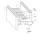
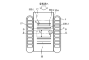
- FIG. 1 is a diagram showing the configuration of a heat exchanger 10 according to the first embodiment.
- the heat exchanger 10 of Embodiment 1 is a corrugated fin tube type heat exchanger 10 that is a parallel piping type.
- the heat exchanger 10 includes a plurality of flat heat exchanger tubes 1, a plurality of corrugated fins 2, a lower header 3A, and an upper header 3B.
- the vertical direction of the paper surface in FIG. 1 will be defined as the height direction of the heat exchanger 10.
- the left-right direction of the paper surface in FIG. 1 is assumed to be the horizontal direction.
- the front-rear direction in FIG. 1 is defined as the depth direction of the heat exchanger 10.
- the lower header 3A is a pipe that is pipe-connected to other devices constituting the air conditioner, into which refrigerant, which is a fluid serving as a heat exchange medium, flows in and out, and which branches or merges the refrigerant.
- the upper header 3B is a pipe that is pipe-connected to other devices constituting the air conditioner, through which refrigerant, which is a fluid serving as a heat exchange medium, flows in and out, and branches or merges the refrigerant.
- a plurality of flat heat exchanger tubes 1 are arranged in parallel between the lower header 3A and the upper header 3B so as to be perpendicular to the lower header 3A and the upper header 3B.
- the lower header 3A and the upper header 3B are vertically arranged vertically. Liquid refrigerant passes through the lower header 3A.
- a gaseous refrigerant passes through the upper header 3B.
- Each flat heat exchanger tube 1 is arranged at equal intervals in the horizontal direction with a space between adjacent flat heat exchanger tubes 1.
- the flat heat exchanger tubes 1 are inserted into insertion holes (not shown) of the lower header 3A and the upper header 3B, and are brazed and joined.
- the brazing material for brazing for example, a brazing material containing aluminum is used.
- the heat exchanger 10 When the heat exchanger 10 is used as a condenser or a radiator, a high temperature and high pressure refrigerant flows through the refrigerant flow path in the flat heat exchanger tube 1. Furthermore, when the heat exchanger 10 is used as an evaporator or a cooler, a low-temperature and low-pressure refrigerant flows through the refrigerant flow path within the flat heat exchanger tubes 1 .
- the arrows in FIG. 1 indicate the flow direction of the refrigerant when the heat exchanger 10 functions as an evaporator or a cooler.
- the refrigerant flows into either the lower header 3A or the upper header 3B via piping (not shown) that supplies the refrigerant to the heat exchanger 10 from an external device (not shown).
- the refrigerant flowing into either the lower header 3A or the upper header 3B is distributed and passes through each flat heat exchanger tube 1.
- the flat heat exchanger tube 1 performs heat exchange between a refrigerant passing inside the tube and air, which is a fluid passing outside the tube. At this time, the refrigerant radiates heat to or absorbs heat from the air while passing through the flat heat exchanger tube 1.
- the temperature of the refrigerant is higher than the temperature of the air, the refrigerant releases its own heat to the air. If the temperature of the refrigerant is lower than the temperature of the air, the refrigerant absorbs heat from the air.
- the refrigerant that has passed through the flat heat exchanger tubes 1 and has undergone heat exchange flows into the other of the lower header 3A or the upper header 3B, and joins with the refrigerant that has passed through the other flat heat exchanger tubes 1.
- the refrigerant then flows back to an external device (not shown) through a pipe (not shown) connected to the other of the lower header 3A or the upper header 3B.
- Corrugated fins 2 are arranged between the mutually opposing flat surfaces of the arranged flat heat exchanger tubes 1.
- the corrugated fins 2 are arranged to increase the heat transfer area between the refrigerant and the air.
- the corrugated fin 2 is constructed by corrugating a plate material. Specifically, the plate material is folded into a wavy or bellows shape by repeating mountain folds and valley folds. Here, the bent portion due to the unevenness formed in the wave shape becomes the top portion 2A of the wave shape.
- the corrugated fin 2 has a fin portion 21 (see FIG. 2) that is a flat surface and a top portion 2A that forms a curved surface between the fin portions 21. In the first embodiment, the top portions 2A of the corrugated fins 2 are aligned in the height direction.
- FIG. 2 is a schematic perspective view of the flat heat exchanger tube 1 and corrugated fins 2 according to the first embodiment.
- FIG. 3 is a schematic diagram of the fin portion 21 of the corrugated fin 2 according to the first embodiment when viewed from above.
- DD indicates a center line passing through the center of the fin portion 21 in the depth direction.
- the flat heat exchanger tube 1 has a flat cross section.
- the longitudinal direction of the flat shape is parallel to the depth direction, which is the direction of air flow, and the outer surface along the depth direction is planar.
- the outer surface of the flat shape along the transverse direction perpendicular to the longitudinal direction is a curved heat exchanger tube.
- the flat heat exchanger tube 1 is a multi-hole flat heat exchanger tube that has a plurality of holes that serve as refrigerant flow paths inside the tube.
- the holes in the flat heat exchanger tubes 1 serve as flow paths for the refrigerant between the lower header 3A and the upper header 3B shown in FIG. 1, and are formed along the height direction.
- Each flat heat exchanger tube 1 is arranged with a space between adjacent flat heat exchanger tubes 1 so that the outer surfaces along the longitudinal side of the flat shape face each other.
- the corrugated fin 2 has one end portion 2B that protrudes upstream from between the opposing flat heat exchanger tubes 1 in the air flow direction. Except for the top portion 2A at the one end portion 2B, the corrugated top portion 2A of the corrugated fin 2 and the flat surface of the flat heat exchanger tube 1 are in surface contact with each other. The contact portions are brazed and joined using a brazing filler metal.
- the material of the plate material of the corrugated fin 2 is, for example, an aluminum alloy.
- the surface of the plate material is clad with a brazing material layer.
- the cladding brazing material layer is, for example, an aluminum-silicon-based brazing material containing aluminum.
- the thickness of the plate material is approximately 30 ⁇ m to 200 ⁇ m.
- Each fin portion 21 has a louver portion 22 which is a heat transfer promoting portion projecting upward, and a first drainage space 23D_1.
- the louver portion 22 is an elongated wing plate.
- a plurality of louver portions 22 are provided in each fin portion 21 in a row at intervals in the depth direction, which is the air flow direction. That is, the plurality of louver parts 22 are lined up along the airflow.
- FIG. 2 shows how the condensed water 4 generated on the fin portion 21 is drained into the first drainage space 23D_1.
- the fin section 21 includes a first heat transfer promoting section group 25A and a second heat transfer promoting section group 25B.
- the first heat transfer promoting section group 25A is provided in an upstream region in the air flow direction with respect to the center line DD of the fin section 21.
- the first heat transfer promoting section group 25A includes two louver sections 22, a first drainage space 23D_1, a second drainage space 23D_2, and a third drainage space 23D_3.
- two louver sections 22 are shown in FIG. 3, three louver sections 22 or four or more louver sections 22 may be provided as shown in FIG.
- the plurality of louver sections 22 include a first louver section 22_1 disposed at the most upstream side in the air flow direction, and a second louver section 22_2 disposed at the most downstream side in the air flow direction.
- the first drainage space 23D_1 is provided between the first louver part 22_1 and the fin part 21 on the upstream side in the flow direction closest to the first louver part 22_1.
- the first drainage space 23D_1 is an opening that passes through the fin portion 21, and has a rectangular shape when viewed from above perpendicular to the flat surface of the fin portion 21.
- the second drainage space 23D_2 is provided between adjacent louver parts 22.
- the louver portion 22 of this embodiment is formed by cutting and raising a plate material that constitutes the fin portion 21 .
- the space between the fin parts 21 formed by cutting and raising is the second drainage space 23D_2.
- the third drainage space 23D_3 is provided between the second louver part 22_2 and the fin part 21 on the downstream side in the flow direction closest to the second louver part 22_2.
- the third drainage space 23D_3 is an opening that passes through the fin portion 21, and has a rectangular shape when viewed from above perpendicularly to the flat surface of the fin portion 21.
- the area of the first drainage space 23D_1 is wider than the area of the second drainage space 23D_2. Furthermore, in this embodiment, the area of the third drainage space 23D_3 when viewed perpendicularly to the fin portion 21 is larger than the area of the second drainage space 23D_2.
- the second heat transfer promoting section group 25B is provided in a region downstream of the center line DD of the fin section 21 in the air flow direction.
- the second heat transfer promoting section group 25B includes two louver sections 22, a first drainage space 23D_1, a second drainage space 23D_2, and a third drainage space 23D_3.
- two louver sections 22 are shown in FIG. 3, three louver sections 22 or four or more louver sections 22 may be provided as shown in FIG.
- the plurality of louver sections 22 include a first louver section 22_1 disposed at the most upstream side in the air flow direction, and a second louver section 22_2 disposed at the most downstream side in the air flow direction.
- the first drainage space 23D_1 is provided between the first louver part 22_1 and the fin part 21 on the upstream side in the flow direction closest to the first louver part 22_1.
- the first drainage space 23D_1 is an opening that passes through the fin portion 21, and has a rectangular shape when viewed from above perpendicular to the flat surface of the fin portion 21.
- the second drainage space 23D_2 is provided between adjacent louver parts 22.
- the third drainage space 23D_3 is provided between the second louver part 22_2 and the fin part 21 on the downstream side in the flow direction closest to the second louver part 22_2.
- the third drainage space 23D_3 is an opening that passes through the fin portion 21, and has a rectangular shape when viewed from above perpendicularly to the flat surface of the fin portion 21.
- the area of the first drainage space 23D_1 is wider than the area of the second drainage space 23D_2. Furthermore, in this embodiment, the area of the third drainage space 23D_3 when viewed perpendicularly to the fin portion 21 is larger than the area of the second drainage space 23D_2.
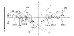
- FIG. 4 is a schematic vertical cross-sectional view of the fin portion 21 of the corrugated fin 2 according to the first embodiment.
- FIG. 4 shows an example in which three louver parts 22 are provided in the first heat transfer promoting part group 25A along the air flow direction. Further, in the second heat transfer promoting section group 25B, an example is shown in which three louver sections 22 are provided along the air flow direction.
- AA A virtual line indicating the inclination of the louver portion 22 of the first heat transfer promoting portion group 25A with respect to the fin portion 21.
- BB A virtual line indicating the inclination of the louver portion 22 of the second heat transfer promoting portion group 25B with respect to the fin portion 21.
- LL is the distance between adjacent louver parts 22 in a plane along the fin part 21.
- L P is the distance between the centers of adjacent louver parts 22 on the plane along the fin part 21 .
- Ls is the distance between the gaps between adjacent louver parts 22.
- ⁇ is the inclination angle of the louver portion 22 with respect to the fin portion 21. LL and LP are equal.
- S L on the upstream side in the air flow direction in the first heat transfer promoting section group 25A is the distance between the first louver section 22_1 and the fin section 21 on the upstream side in the flow direction closest to the first louver section 22_1. It is. That is, SL on the upstream side in the air flow direction in the first heat transfer promoting section group 25A is the length of the first drainage space 23D_1 when viewed perpendicularly to the flat surface of the fin section 21.
- S L on the downstream side in the air flow direction in the first heat transfer promoting section group 25A is the distance between the second louver section 22_2 and the fin section 21 on the downstream side in the flow direction closest to the second louver section 22_2. It is. That is, SL on the downstream side in the air flow direction in the first heat transfer promoting section group 25A is the length of the third drainage space 23D_3 when viewed perpendicularly to the flat surface of the fin section 21.
- LL in the first heat transfer promoting section group 25A is the distance between adjacent louver sections 22 in the first heat transfer promoting section group 25A. That is, LL in the first heat transfer promoting section group 25A is the length of the second drainage space 23D_2 in the air flow direction when viewed perpendicularly to the fin section 21.
- the length of S L on the downstream side in the air flow direction in the first heat transfer promoting section group 25A is longer than the length of L L in the first heat transfer promoting section group 25A.
- S L on the upstream side in the air flow direction in the second heat transfer promoting section group 25B is the distance between the first louver section 22_1 and the fin section 21 on the upstream side in the flow direction closest to the first louver section 22_1. It is. That is, SL on the upstream side in the air flow direction in the first heat transfer promoting section group 25A is the length of the first drainage space 23D_1 when viewed perpendicularly to the flat surface of the fin section 21.
- S L on the downstream side in the air flow direction in the second heat transfer promoting section group 25B is the distance between the second louver section 22_2 and the fin section 21 on the downstream side in the flow direction closest to the second louver section 22_2. It is. That is, SL on the downstream side in the air flow direction in the first heat transfer promoting section group 25A is the length of the third drainage space 23D_3 when viewed perpendicularly to the flat surface of the fin section 21.
- LL in the second heat transfer promoting section group 25B is the distance between adjacent louver sections 22 in the second heat transfer promoting section group 25B. That is, LL in the second heat transfer promoting section group 25B is the length of the second drainage space 23D_2 in the air flow direction when viewed perpendicularly to the fin section 21.
- the length of S L on the downstream side in the air flow direction in the second heat transfer promoting section group 25B is longer than the length of L L in the second heat transfer promoting section group 25B.
- the heat exchanger 10 of the first embodiment has a first drainage space 23D_1 which is wider than a second drainage space 23D_2 between the adjacent louver parts 22 between the fin part 21 and the louver part 22 adjacent to the fin part 21. and a third drainage space 23D_3. Therefore, the relationship S L >L L holds true.
- first heat transfer promoting section group 25A shown in FIG. 4 three louver sections 22 are arranged in parallel with an interval between them.
- first heat transfer promoting section group 25A the gap formed on the outside of the louver section 22 at the end is larger than the gap between the louver sections 22 in the first heat transfer promoting section group 25A.
- second heat transfer promoting part group 25B the gap formed on the outside of the louver part 22 at the end is larger than the gap between the louver parts 22 in the second heat transfer promoting part group 25B.
- a part of the outer periphery of the first drainage space 23D_1 is formed by the edge of the first louver part 22_1 on the most upstream side. That is, the first louver portion 22_1 and the first drainage space 23D_1 are directly adjacent to each other without any other member or space between them.
- a part of the outer periphery of the third drainage space 23D_3 is formed by the edge of the second louver portion 22_2 on the most downstream side. In other words, the second louver portion 22_2 and the third drainage space 23D_3 are directly adjacent to each other without any other member or space between them.
- the shapes of the first drainage space 23D_1 and the third drainage space 23D_3 have been described as having a rectangular shape when viewed from above as shown in FIG. 3, but the shape is limited to a rectangular shape. It's not a thing.
- FIG. 5 is a schematic top view of the fin portion 21 of the corrugated fin 2 having the first drainage space 23D_1 and the third drainage space 23D_3 according to the modified example of the first embodiment.
- the first drainage space 23D_1 and the third drainage space 23D_3 include a curved line in part of their shape when viewed perpendicularly to the fin portion 21.
- the first drainage space 23D_1 and the third drainage space 23D_3 have a D-shaped outer shape.
- the edge of the louver portion 22 that defines the first drainage space 23D_1, extending from one flat heat exchanger tube 1 toward the other flat heat exchanger tube 1, is a curve
- a part of the shape of the first drainage space 23D_1 is It is a curved line.
- the edges of the fin portions 21 that define the third drainage space 23D_3, extending from one flat heat exchanger tube 1 toward the other flat heat exchanger tube 1, are curved, the shape of the third drainage space 23D_3 is uniform. The part is curved.
- the curves of the first drainage space 23D_1 and the third drainage space 23D_3 are curves that are convex in the air flow direction, with the apex 2A located between the flat heat exchanger tubes 1.
- FIG. 5 shows an example in which the curves of the first drainage space 23D_1 and the third drainage space 23D_3 are curves that are convex in the air flow direction, they are curves that are convex in the opposite direction to the air flow direction. It may be a curve.
- condensed water 4 generated on the corrugated fins 2 passes through the drainage space between the louver parts 22 (second drainage space 23D_2 in the embodiment) and flows down.
- the amount of the condensed water 4 flowing from the fin section 21 adjacent to the louver section 22 toward the louver section 22 in the air flow direction is It is larger than the amount of condensed water 4 flowing on the surface.
- the first drainage space 23D_1 is provided between the first louver part 22_1 and the fin part 21 on the upstream side in the air flow direction closest to the first louver part 22_1.
- a second drainage space 23D_2 is provided between the adjacent louver parts 22, and the area of the first drainage space 23D_1 when viewed perpendicularly to the fin part 21 is larger than the area of the second drainage space 23D_2. wide.
- the condensed water 4 generated on the flat fin portion 21 of the corrugated fin 2 is pushed by the air flow and flows on the fin portion 21 from upstream to downstream.
- the air then reaches the first drainage space 23D_1 between the first louver part 22_1, which is a heat transfer promoting part, and the fin part 21 on the upstream side in the air flow direction, and flows down from the first drainage space 23D_1. Since the first drainage space 23D_1 has a relatively large area as described in the first embodiment, most of the condensed water 4 flows down from the first drainage space 23D_1. Therefore, drainage of condensed water 4 generated on the fin portions 21 of the corrugated fins 2 is improved.
- drainability refers to the amount of water drained from the heat exchanger 10 per unit time.
- first drainage space 23D_1 between the adjacent fin part 21 and the first louver part 22_1 relatively large, it is possible to prevent the condensed water 4 from staying in the first drainage space 23D_1, that is, between the fin part 21 and the first louver part. Bridging of the condensed water 4 with the portion 22_1 can be suppressed.
- the condensed water 4 flows down the gap between the louver parts 22 and is drained, but at this time, much of the condensed water 4 is introduced from the fin parts 21. Therefore, it has been found that by providing the first drainage space 23D_1 which is wider than the second drainage space 23D_2, drainage performance can be effectively improved. Further, the area of the second drainage space 23D_2 provided between the louver parts 22 of the corrugated fins 2 is smaller than the area of the first drainage space 23D_1. Therefore, the decrease in the heat transfer area of the corrugated fins 2 can be reduced, and thereby the decrease in heat transfer performance can be suppressed.
- the first drainage space 23D_1 is provided in an area on the upstream side of the air flow where the amount of moisture contained in the air is large, so that frost can be retained.
- the number of areas to do increases. That is, more frost adheres to and is retained around the first drainage space 23D_1.
- the plurality of louver sections 22 include the second louver section 22_2 disposed on the most downstream side in the air flow direction;
- a third drainage space 23D_3 is provided between the fin part 21 on the downstream side in the air flow direction closest to the part 22_2, and the area of the third drainage space 23D_3 when viewed perpendicularly to the fin part 21 is: It is wider than the area of the second drainage space 23D_2.
- the condensed water 4 generated on the flat fin portion 21 of the corrugated fin 2 is pushed by the air flow and flows on the fin portion 21 from upstream to downstream. Then, it reaches the third drainage space 23D_3 between the second louver part 22_2 and the fin part 21, which are heat transfer promoting parts located on the downstream side in the air flow direction, and flows down from the third drainage space 23D_3. Since the third drainage space 23D_3 has a relatively large area as described in the first embodiment, most of the condensed water 4 flows down from the third drainage space 23D_3. Therefore, drainage of condensed water 4 generated on the fin portions 21 of the corrugated fins 2 is improved.
- the third drainage space 23D_3 between the adjacent fin part 21 and the second louver part 22_2 relatively large, it is possible to prevent the condensed water 4 from staying in the third drainage space 23D_3, that is, between the fin part 21 and the second louver part. Bridging of the condensed water 4 with the portion 22_2 can be suppressed.
- the heat transfer performance of the portion of the fin portion 21 with low fin efficiency Drainage performance can be further improved while suppressing the decrease in water as much as possible.
- the shapes of the first drainage space 23D_1 and the third drainage space 23D_3 are such that the opening space is larger toward the center of the opening area, the drainage performance can be further improved while suppressing deterioration of heat transfer performance as much as possible.
- FIG. 6 is a schematic top view of the corrugated fin 2 according to the second embodiment. Note that the same parts as in FIG. 3 are given the same reference numerals, and different parts will be explained here.
- the opening area of the first drainage space 23D_1 in the first heat transfer promoting part group 25A is larger than the opening area of the third drainage space 23D_3 in the first heat transfer promoting part group 25A. It's also big.
- the sum of the opening areas of the plurality of louvers 22 in the first heat transfer promoting part group 25A is larger than the sum of the opening areas of the plurality of louvers 22 in the second heat transfer promoting part group 25B.
- A1 the sum of the opening areas of the plurality of louvers 22 in the first heat transfer promoting part group 25A
- B1 B 1
- a 1 > B 1
- the total opening area is the opening area of the first drainage space 23D_1, the second drainage space 23D_2, and the third drainage space 23D_3.
- the amount of heat exchanged by the heat exchanger 10 is large in the upstream portion of the fin portion 21 in the air flow direction where the temperature difference between the air and the temperature of the refrigerant flowing in the flat heat exchanger tube 1 is large. Therefore, the amount of condensed water 4 generated is also greater on the upstream side in the air flow direction.
- the total opening area of the drainage spaces in the first heat transfer promoting section group 25A on the upstream side of the center line DD of the fin section 21 in the air flow direction is It is larger than the total opening area of the drainage spaces in the second heat transfer promoting section group 25B on the downstream side in the flow direction. Therefore, the heat exchanger 10 of the second embodiment has improved drainage performance compared to the heat exchanger 10 of the first embodiment.
- the first drainage space 23D_1 on the upstream side in the air flow direction has a larger opening area than the third drainage space 23D_3 on the downstream side in the air flow direction. Since it is also large, drainage performance is further improved.
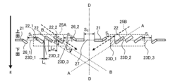
- FIG. 7 is a side sectional view of the fin portion 21 of the corrugated fin 2 according to the third embodiment. Note that the same parts as in FIG. 4 are given the same reference numerals, and different parts will be explained here.
- the plurality of louver parts 22 in the first heat transfer promoting part group 25A are arranged at an angle with respect to the fin part 21.
- the fin portion 21 on the upstream side in the air flow direction closest to the first louver portion 22_1 has a first slope portion 26_1 that slopes parallel to the slope direction of the first louver portion 22_1.
- the fin part 21 on the downstream side in the air flow direction closest to the second louver part 22_2 has a second slope part 26_2 that slopes parallel to the slope direction of the second louver part 22_2.
- the first inclined portion 26_1 of the fin portion 21 on the upstream side in the air flow direction closest to the first louver portion 22_1 in the first heat transfer promoting portion group 25A is formed in a direction that protrudes toward the lower surface side with respect to the fin portion 21. Ru.
- the second inclined portion 26_2 of the fin portion 21 on the downstream side in the air flow direction closest to the first louver portion 22_1 in the first heat transfer promoting portion group 25A is formed in a direction that protrudes toward the upper surface side with respect to the fin portion 21. Ru.
- the area of the first drainage space 23D_1 provided between the first inclined part 26_1 and the first louver part 22_1 in the first heat transfer promoting part group 25A when viewed perpendicularly to the fin part 21 is the same as that of the adjacent louver. It is larger than the area of the second drainage space 23D_2 provided between the sections 22.
- the area of the third drainage space 23D_3 provided between the second inclined portion 26_2 and the second louver portion 22_2 in the first heat transfer promoting portion group 25A is equal to the area of the adjacent louver. It is larger than the area of the second drainage space 23D_2 provided between the sections 22.
- the plurality of louver parts 22 in the second heat transfer promoting part group 25B are arranged at an angle with respect to the fin part 21.
- the fin portion 21 on the upstream side in the air flow direction closest to the first louver portion 22_1 has a first slope portion 26_1 that slopes parallel to the slope direction of the first louver portion 22_1.
- the fin part 21 on the downstream side in the air flow direction closest to the second louver part 22_2 has a second slope part 26_2 that slopes parallel to the slope direction of the second louver part 22_2.
- the first inclined part 26_1 of the fin part 21 on the upstream side in the air flow direction closest to the first louver part 22_1 in the second heat transfer promoting part group 25B is formed in a direction that protrudes toward the upper surface side with respect to the fin part 21. Ru.
- the second inclined portion 26_2 of the fin portion 21 on the downstream side in the air flow direction closest to the first louver portion 22_1 in the second heat transfer promoting portion group 25B is formed in a direction protruding toward the lower surface side with respect to the fin portion 21. Ru.
- the first drainage space 23D_1 provided between the first inclined part 26_1 and the first louver part 22_1 in the second heat transfer promoting part group 25B is larger than the second drainage space 23D_2 provided between the adjacent louver parts 22. It's also big.
- the third drainage space 23D_3 provided between the second inclined part 26_2 and the second louver part 22_2 in the second heat transfer promoting part group 25B is larger than the second drainage space 23D_2 provided between the adjacent louver parts 22. It's also big.
- the area of the corrugated fins 2 that contributes to heat exchange is increased by the first sloped portion 26_1 and the second sloped portion 26_2, so that the heat transfer performance of the corrugated fins 2 can be improved.
- the first drainage space 23D_1 of the first heat transfer promoting section group 25A is viewed along the inclination of the louver section 22 (in the direction of the thick broken line arrow in FIG. 7), the first inclined section 26_1 and the first louver section 22_1, a flow path along this inclination is formed.
- the flow path between the first inclined portion 26_1 and the first louver portion 22_1 becomes a drainage path for the condensed water 4. Therefore, compared to the case where the first inclined portion 26_1 is not provided, the drainage performance of the corrugated fin 2 can be improved while improving the heat transfer performance.
- the second slope part 26_2 makes the third drainage space 23D_3 a larger opening when viewed along the slope of the louver part 22 (in the direction of the thick arrow in FIG. 7). Become. Therefore, the drainage performance of the corrugated fins 2 can be improved.
- FIG. 8 is a side sectional view of the fin portion 21 of the corrugated fin 2 according to the fourth embodiment. Note that the same parts as in FIG. 4 are given the same reference numerals, and different parts will be explained here.
- a flat drainage slit 27 which is a fourth drainage space for draining condensed water 4, is provided in the fin portion 21 near the center of the fin in the air flow direction.
- the flat drainage slit 27 is provided between the first heat transfer promoting section group 25A and the second heat transfer promoting section group 25B.
- FIG. 8 is not shown, as can be seen from FIGS. 1 and 2, a plurality of fin portions 21 are arranged in a line in the vertical direction, and the flat drainage slits 27 of each fin portion 21 are also arranged in a line in a vertical direction. Placed.
- the orientation of the louver portion 22 is such that the condensed water 4 (not shown) flows into the flat drain slit 27 of the fin portion 21 on the lower stage of the fin portion 21 where the louver portion 22 is provided. They are oriented so that they can gather together.
- the dashed arrow in FIG. 8 represents the direction in which the condensed water 4 is drained.
- the condensed water 4 that has flowed down along the surface of the louver section 22 falls toward the flat section drainage slit 27 of the fin section 21 located at the lower stage of this louver section 22, and the condensed water 4 flows down along the surface of the louver section 22 and falls toward the flat section drainage slit 27 of the fin section 21 located at the lower stage of this louver section 22. Falling down from 27.
- the louver portions 22 By arranging the louver portions 22 in this manner, the drainage performance of the condensed water 4 can be improved.
- the direction of inclination of the plurality of louvers 22 in the first heat transfer promoting part group 25A with respect to the fin part 21 is such that the plurality of louver parts 22 in the second heat transfer promoting part group 25B are inclined with respect to the flat part drainage slit 27.
- This direction is opposite to the direction of inclination with respect to the fin portion 21. Therefore, both the condensed water 4 that has fallen from the first heat transfer promoting section group 25A and the condensed water 4 that has fallen from the second heat transfer promoting section group 25B flow toward one flat drainage slit 27.
- FIG. 9 is a schematic top view of the fin portion 21 of the corrugated fin 2 according to the fourth embodiment. Note that the same parts as in FIG. 3 are given the same reference numerals, and different parts will be explained here.
- the opening area of the flat drainage slit 27 is larger than the total opening area of the first heat transfer promoting section group 25A.
- the total opening area of the first heat transfer promoting section group 25A is the sum of the opening areas of the first drainage space 23D_1, the second drainage space 23D_2, and the third drainage space 23D_3.
- S s is the distance of the flat drainage slit 27 in the air flow direction.
- the flat drainage slit 27 is one rectangular opening.
- the flat drainage slit 27 may be configured with a plurality of openings. good.
- FIG. 10 is a side sectional view of the fin portion 21 of the corrugated fin 2 according to a modification of the fourth embodiment.
- the same parts as in FIG. 4 are given the same reference numerals, and different parts will be explained here.
- FIG. 11 is a schematic top view of the fin portion 21 of the corrugated fin 2 according to a modification of the fourth embodiment.
- the same parts as in FIG. 3 are given the same reference numerals, and different parts will be explained here.
- the opening shape of the flat drainage slit 27 is not limited to a rectangular shape.
- the opening area of the flat drainage slit 27 is larger than the total opening area of the first heat transfer promoting section group 25A.
- the fin portions 21 are arranged vertically. Therefore, in the corrugated fin 2, the condensed water 4 introduced from the first heat transfer promoting part group 25A and the second heat transfer promoting part group 25B of the upper fin part 21 is drained from the flat part of the lower fin part 21.
- the slit 27 allows drainage. Therefore, the drainage performance of the heat exchanger 10 is improved.
- FIG. 12 is a side sectional view of the fin portion 21 of the corrugated fin 2 according to the fifth embodiment.
- the same parts as in FIG. 4 are given the same reference numerals, and different parts will be explained here.
- the inclination angle ⁇ of the louver part 22 with respect to the flat surface of the fin part 21 is different from the inclination angle ⁇ of the louver part 22 adjacent to each other in the air flow direction.
- the inclination angle of the louver part 22 with respect to the first louver part 22_1 is ⁇ 1
- the inclination angle with respect to the louver part 22 is ⁇ 2
- the inclination angle of the second louver part 22_2 is ⁇ 3.
- ⁇ 1 ⁇ 2 ⁇ 3 holds true.
- the inclination angle ⁇ 1, the inclination angle ⁇ 2, and the inclination angle ⁇ 3 in the first heat transfer promoting portion group 25A are different from each other.
- the inclination angle ⁇ 3 of the second louver portion 22_2 in the first heat transfer promoting portion group 25A is larger than the inclination angle ⁇ 1 of the first louver portion 22_1.
- the inclination angle ⁇ 1, the inclination angle ⁇ 2, and the inclination angle ⁇ 3 in the second heat transfer promoting portion group 25B are different from each other.
- the inclination angle ⁇ 3 of the second louver portion 22_2 in the second heat transfer promoting portion group 25B is larger than the inclination angle ⁇ 1 of the first louver portion 22_1.
- the inclination angle ⁇ 2 of the second louver part 22_2 on the downstream side in the air flow direction is relative to the inclination angle ⁇ 1 of the first louver part 22_1 on the upstream side in the air flow direction. is large. Therefore, the heat transfer coefficient on the upstream side in the flow direction of air with a large amount of frost formation can be suppressed, and the frost resistance can be improved.
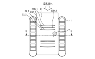
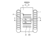
- FIG. 13 is a diagram showing the configuration of an air conditioner A according to Embodiment 6.
- an air conditioner A will be described as an example of a refrigeration cycle device.
- the heat exchanger 10 is used as an outdoor heat exchanger 230.
- the present invention is not limited to this, and may be used as the indoor heat exchanger 110 or both the outdoor heat exchanger 230 and the indoor heat exchanger 110.
- a refrigerant circuit is configured by connecting an outdoor unit 200 and an indoor unit 100 through gas refrigerant piping 300 and liquid refrigerant piping 400.
- the outdoor unit 200 includes a compressor 210, a four-way valve 220, an outdoor heat exchanger 230, and an outdoor fan 240.
- the air conditioner A of Embodiment 1 it is assumed that one outdoor unit 200 and one indoor unit 100 are connected by piping.
- the compressor 210 compresses and discharges the sucked refrigerant.
- the capacity of the compressor 210 can be changed by arbitrarily changing the operating frequency of the compressor 210 using, for example, an inverter circuit.
- the four-way valve 220 is a valve that switches the flow of refrigerant depending on, for example, cooling operation and heating operation.
- the outdoor heat exchanger 230 exchanges heat between the refrigerant and outdoor air. For example, during heating operation, it functions as an evaporator and evaporates the refrigerant. Also, during cooling operation, it functions as a condenser, condensing and liquefying the refrigerant.
- the outdoor fan 240 sends outdoor air to the outdoor heat exchanger 230 and promotes heat exchange in the outdoor heat exchanger 230.
- the indoor heat exchanger 110 exchanges heat between indoor air to be air-conditioned and a refrigerant, for example. During heating operation, it functions as a condenser, condensing and liquefying the refrigerant. Also, during cooling operation, it functions as an evaporator and evaporates and vaporizes the refrigerant.
- the indoor unit 100 includes an indoor heat exchanger 110, an expansion valve 120, and an indoor fan 130.
- the expansion valve 120 such as a throttle device, depressurizes and expands the refrigerant.
- the opening degree is adjusted based on instructions from a control device (not shown) or the like.
- the indoor heat exchanger 110 performs heat exchange between indoor air, which is a space to be air-conditioned, and a refrigerant.
- a condenser to condense and liquefy the refrigerant.
- it functions as an evaporator and evaporates and vaporizes the refrigerant.
- the indoor fan 130 causes indoor air to pass through the indoor heat exchanger 110, and supplies the air that has passed through the indoor heat exchanger 110 into the room.
- each device of the air conditioner A will be explained based on the flow of refrigerant.
- the high temperature and high pressure gas refrigerant compressed and discharged by the compressor 210 passes through the four-way valve 220 and flows into the indoor heat exchanger 110. While passing through the indoor heat exchanger 110, the gas refrigerant condenses and liquefies, for example, by exchanging heat with the air in the air-conditioned space. The condensed and liquefied refrigerant passes through the expansion valve 120. When the refrigerant passes through the expansion valve 120, its pressure is reduced.
- the refrigerant whose pressure is reduced by the expansion valve 120 and becomes a gas-liquid two-phase state passes through the outdoor heat exchanger 230.
- the refrigerant that is evaporated and gasified by exchanging heat with the outdoor air sent from the outdoor fan 240 passes through the four-way valve 220 and is sucked into the compressor 210 again.
- the refrigerant of the air conditioner A circulates to perform air conditioning related to heating.
- the high temperature and high pressure gas refrigerant compressed and discharged by the compressor 210 passes through the four-way valve 220 and flows into the outdoor heat exchanger 230.
- the refrigerant passes through the outdoor heat exchanger 230 and is condensed and liquefied by exchanging heat with outdoor air supplied by the outdoor fan 240 , and then passes through the expansion valve 120 .
- the expansion valve 120 When the refrigerant passes through the expansion valve 120, its pressure is reduced.
- the refrigerant whose pressure is reduced by the expansion valve 120 and becomes a gas-liquid two-phase state passes through the indoor heat exchanger 110.
- the refrigerant that is evaporated and gasified by exchanging heat with the air in the air-conditioned space passes through the four-way valve 220 and is sucked into the compressor 210 again.
- the refrigerant of the air conditioner A circulates and air conditioning related to cooling is performed.
- the heat exchanger 10 acts as an evaporator
- the surfaces of the flat heat exchanger tubes 1 and corrugated fins 2 have a temperature lower than that of the air passing through the heat exchanger 10. Therefore, moisture in the air condenses on the surfaces of the flat heat exchanger tubes 1 and the corrugated fins 2, and condensed water 4 is precipitated.
- the air temperature is even lower, the fin surface temperature drops below freezing, and the condensed water 4 on the fin surface freezes and grows as frost, blocking the air flow and increasing the air flow resistance.
- the amount of air flowing through the heat exchanger 10 decreases, thereby reducing the performance of the heat exchanger 10.
- the heat exchanger 10 shown in Embodiment 1, Embodiment 2, Embodiment 3, Embodiment 4, and Embodiment 5 is used. Therefore, in the heat exchanger 10, retention of condensed water 4 can be suppressed and drainage performance can be improved. Furthermore, since the first drainage space 23D_1 and the third drainage space 23D_3 increase the area for retaining frost, it is possible to extend the blockage time of the air flow between the fin portions 21, and improve frost resistance. As a result, the heat exchanger 10 of the air conditioner A of Embodiment 6 can reduce the decrease in the heat transfer area of the corrugated fins 2 during frost conditions, and can suppress the decrease in heat transfer performance. .
- the louver part 22 is also called a heat transfer promotion part, and the flat part drainage slit 27 is also called a fourth drainage space.
Abstract
熱交換器は、空気の流れ方向と交差する方向に間隔を空けて並設された複数の伝熱管と、平坦な面であるフィン部と、隣り合う複数の伝熱管の一方から他方に向かって延び、フィン部に対して傾斜して配置された複数の伝熱促進部を有する1又は複数の伝熱促進部群とを具備し、複数の伝熱管の間に配置されたコルゲートフィンとを具備し、複数の伝熱促進部は、空気の流れ方向の最も上流側に配置された第1伝熱促進部を含み、第1伝熱促進部と、第1伝熱促進部に最も近い空気の流れ方向の上流側のフィン部との間には第1排水空間が設けられ、隣り合う伝熱促進部の間には第2排水空間が設けられ、フィン部に垂直に見た状態における、第1排水空間の面積は、第2排水空間の面積よりも広い。
Description
本開示は、熱交換器及び空気調和装置に関する。
冷媒が通過する一対のヘッダー間に接続された複数の扁平伝熱管の間に、コルゲートフィンを配置したコルゲートフィンチューブ型の熱交換器が普及している。
コルゲートフィンが配置された扁平伝熱管と扁平伝熱管の間には、気体が気流として通過する。このような熱交換器において、扁平伝熱管とコルゲートフィンとの少なくとも一方の表面温度が氷点以下になる可能性がある。表面温度が低下すると、表面近くの空気中の水分が析出して水となり、さらに、氷点以下になると、水が凍結する。そこで、排水をはかるため、フィン部分にスリットを設け、表面に析出した水を、スリットを介して排出する熱交換器がある(例えば、特許文献1参照)。
従来の熱交換器は、前述したように、コルゲートフィン表面に析出する水を排出する構造を有する。しかし、凝縮水を排水するために開口面積を多くとる必要があり、これによってコルゲートフィンの伝熱面積が低下し、伝熱性能を低下させる要因となっていた。
本開示は、上記実情に鑑みてなされたものであり、排水性能を向上しながら、伝熱面積の低下を小さくすることで、伝熱性能の低下を抑制することができる熱交換器及び空気調和装置を提供することを目的とする。
本開示に係る熱交換器は、空気の流れ方向と交差する方向に間隔を空けて並設された複数の伝熱管と、平坦な面であるフィン部と、隣り合う前記複数の伝熱管の一方から他方に向かって延び、前記フィン部に対して傾斜して配置された複数の伝熱促進部を有する1又は複数の伝熱促進部群とを具備し、前記複数の伝熱管の間に配置されたコルゲートフィンとを具備し、前記複数の伝熱促進部は、前記空気の流れ方向の最も上流側に配置された第1伝熱促進部を含み、前記第1伝熱促進部と、前記第1伝熱促進部に最も近い前記空気の流れ方向の上流側の前記フィン部との間には第1排水空間が設けられ、隣り合う前記伝熱促進部の間には第2排水空間が設けられ、前記フィン部に垂直に見た状態における、前記第1排水空間の面積は、前記第2排水空間の面積よりも広い。
本開示によれば、フィン部に垂直に見た状態における、第1排水空間の面積は、第2排水空間の面積よりも広い。従って、上流側のフィン部と伝熱促進部との間の第1排水空間の面積を相対的に大きくすることで、この第1排水空間からの排水量が多くなり、本開示の熱交換器は、凝縮水の滞留を抑制し、排水性能を向上できる。また、隣り合う伝熱促進部間の第2排水空間の面積は相対的に小さいので、コルゲートフィンの伝熱面積の低下を小さくすることができ、伝熱性能の低下を抑制することができる。
以下、図面を参照して、実施形態に係る空気調和装置について説明する。なお、図面において、同一の構成要素には同一符号を付して説明し、重複説明は必要な場合にのみ行なう。本開示は、以下の各実施形態で説明する構成のうち、組合せ可能な構成のあらゆる組合せを含み得る。また、図面では各構成部材の大きさの関係が実際のものとは異なる場合がある。そして、明細書全文に表わされている構成要素の形態は、あくまでも例示であって、明細書に記載された形態に限定するものではない。特に構成要素の組み合わせは、各実施形態における組み合わせのみに限定するものではなく、他の実施形態に記載した構成要素を別の実施形態に適用することができる。
実施形態1.
図1は、実施形態1に係る熱交換器10の構成を示す図である。
図1は、実施形態1に係る熱交換器10の構成を示す図である。
図1に示すように、実施形態1の熱交換器10は、パラレル配管形であるコルゲートフィンチューブ型の熱交換器10である。熱交換器10は、複数の扁平伝熱管1、複数のコルゲートフィン2、下部ヘッダー3A及び上部ヘッダー3Bを有する。ここで、以下では、図1における紙面上下方向を、熱交換器10の高さ方向とする。また、図1における紙面左右方向を、水平方向とする。そして、図1における紙面前後方向を、熱交換器10の奥行き方向とする。
下部ヘッダー3Aは、空気調和装置を構成する他の装置と配管接続され、熱交換媒体となる流体である冷媒が流入出し、冷媒を分岐又は合流させる管である。上部ヘッダー3Bは、空気調和装置を構成する他の装置と配管接続され、熱交換媒体となる流体である冷媒が流入出し、冷媒を分岐又は合流させる管である。
下部ヘッダー3Aと上部ヘッダー3Bとの間には、複数の扁平伝熱管1が、下部ヘッダー3Aと上部ヘッダー3Bとに対して垂直となるように、平行に配置されている。下部ヘッダー3Aと上部ヘッダー3Bとは、高さ方向に上下に分かれて配置される。下部ヘッダー3Aには液状の冷媒が通過する。上部ヘッダー3Bには、ガス状の冷媒が通過する。
各扁平伝熱管1は、隣り合う扁平伝熱管1との間に空間をあけて、水平方向に等間隔に配列される。実施形態1の熱交換器10を製造する際、扁平伝熱管1は、下部ヘッダー3Aと上部ヘッダー3Bとが有する挿入穴(図示せず)に挿し込まれ、ろう付けされ、接合される。ろう付けのろう材は、例えばアルミニウムを含むろう材が使用される。
熱交換器10が、凝縮器又は放熱器として使用される場合は、高温及び高圧の冷媒が扁平伝熱管1の管内の冷媒流路を流れる。また、熱交換器10が、蒸発器又は冷却器として使用される場合は、低温及び低圧の冷媒が扁平伝熱管1の管内の冷媒流路を流れる。図1の矢印は、熱交換器10が蒸発器又は冷却器として機能するときの冷媒の流れ方向を示している。冷媒は、外部装置(図示せず)から熱交換器10に冷媒を供給する配管(図示せず)を介して、下部ヘッダー3A又は上部ヘッダー3Bの一方に流入する。下部ヘッダー3A又は上部ヘッダー3Bの一方に流入した冷媒は、分配されて各扁平伝熱管1を通過する。扁平伝熱管1は、管内を通過する冷媒と管外を通過する流体である空気との間で熱交換を行う。このとき、冷媒は、扁平伝熱管1を通過する間に、空気に対して放熱又は空気から吸熱する。冷媒の温度が空気の温度より高い場合には、冷媒は自身が持つ熱を空気に放出する。冷媒の温度が空気の温度より低い場合には、冷媒は、空気から熱を吸収する。扁平伝熱管1を通過して熱交換された冷媒は、下部ヘッダー3A又は上部ヘッダー3Bの他方に流入し、他の扁平伝熱管1を通過した冷媒と合流する。そして、冷媒は、下部ヘッダー3A又は上部ヘッダー3Bの他方に接続された配管(図示せず)を通って、外部装置(図示せず)に還流される。
配列された扁平伝熱管1の互いに対向する扁平面間には、コルゲートフィン2が配列される。コルゲートフィン2は、冷媒と空気との伝熱面積を広げるために配列される。コルゲートフィン2は、板材に対してコルゲート加工が行われて構成される。具体的に、板材が、山折り及び谷折りを繰返すつづら折りされることにより、折り曲げられて波形状にあるいは蛇腹形状となっている。ここで、波形状に形成されてできた凹凸による折り曲げ部分は、波形状の頂部2Aとなる。コルゲートフィン2は、平坦な面であるフィン部21(図2参照)と、フィン部21間の曲面を形成する頂部2Aとを有する。実施形態1において、コルゲートフィン2の頂部2Aは、高さ方向にわたって並んでいる。
図2は、実施形態1に係る扁平伝熱管1及びコルゲートフィン2の概略的な斜視図である。図3は、実施形態1に係るコルゲートフィン2のフィン部21を上面視した場合の概略図である。図3において、D-Dは、フィン部21の奥行き方向における中心を通る中心線を示す。
扁平伝熱管1は、断面が扁平形状を有する。扁平形状の長手方向は、空気の流通方向である奥行き方向と平行であり、この奥行き方向に沿った外側面が平面状である。当該長手方向に直交する扁平形状の短手方向に沿った外側面は、曲面状である伝熱管である。
扁平伝熱管1は、管の内部に、冷媒の流路となる複数の穴を有する多穴扁平伝熱管である。実施形態1において、扁平伝熱管1の穴は、図1に示した下部ヘッダー3Aと上部ヘッダー3Bとの間の冷媒の流路となり、高さ方向に沿って形成される。
各扁平伝熱管1は、扁平形状における長手側に沿った外側面同士が対向するようにして、隣り合う扁平伝熱管1との間に空間をあけて配置される。
コルゲートフィン2は、対向する扁平伝熱管1の間から空気の流通方向において上流側に突出している一端部分2Bを有する。一端部分2Bにおける頂部2Aを除き、コルゲートフィン2において波形状の頂部2Aと扁平伝熱管1の扁平面とは、面接触している。接触部分は、ろう材によってろう付けされ、接合される。コルゲートフィン2の板材の材質は、例えば、アルミニウム合金である。板材表面には、ろう材層がクラッドされる。クラッドされたろう材層は、たとえば、アルミシリコン系のアルミニウムを含むろう材である。ここで、板材の板厚は、30μm~200μm程度である。
コルゲートフィン2の各頂部2Aの間の山腹における平坦な面、すなわち高さ方向に並ぶ頂部2Aと頂部2Aとの間の部分を、フィン部21とする。各フィン部21は、それぞれ上部に突き出た伝熱促進部であるルーバー部22及び第1排水空間23D_1を有する。
ルーバー部22は、細長い羽板である。ルーバー部22は、各フィン部21において空気の流れ方向である奥行き方向に、間隔を空けて複数並んで設けられる。つまり、複数のルーバー部22が、気流に沿って並んでいる。
図2においては、フィン部21上に発生した凝縮水4が第1排水空間23D_1に排水される様子を示している。
図2及び図3に示すように、フィン部21は、第1伝熱促進部群25A及び第2伝熱促進部群25Bを有する。
第1伝熱促進部群25Aは、フィン部21の中心線D-Dに対して、空気の流れ方向の上流側の領域に設けられている。第1伝熱促進部群25Aは、図3においては、2つのルーバー部22、第1排水空間23D_1、第2排水空間23D_2及び第3排水空間23D_3を有する。図3では、2つのルーバー部22を示したが、図2に示すように3つルーバー部22あるいは4つ以上のルーバー部22が設けられていてもよい。
複数のルーバー部22は、空気の流れ方向の最も上流側に配置された第1ルーバー部22_1と、空気の流れ方向の最も下流側に配置された第2ルーバー部22_2とを具備する。
第1排水空間23D_1は、第1ルーバー部22_1と、第1ルーバー部22_1に最も近い流れ方向の上流側のフィン部21との間に設けられる。第1排水空間23D_1は、フィン部21を貫通する開口であり、フィン部21の平坦な面に垂直に上面視した場合の形状が、矩形状である。
第2排水空間23D_2は、隣り合うルーバー部22の間に設けられる。本実施形態のルーバー部22は、フィン部21を構成する板材を切り起こして形成されている。切り起こしによって形成されたフィン部21とフィン部21との間の空間が、第2排水空間23D_2である。
第3排水空間23D_3は、第2ルーバー部22_2と、第2ルーバー部22_2に最も近い流れ方向の下流側のフィン部21との間に設けられる。第3排水空間23D_3は、フィン部21を貫通する開口であり、フィン部21の平坦な面に垂直に上面視した場合の形状が、矩形状である。
フィン部21に垂直に見た状態における、第1排水空間23D_1の面積は、第2排水空間23D_2の面積よりも広い。さらに本実施形態では、フィン部21に垂直に見た状態における、第3排水空間23D_3の面積が、第2排水空間23D_2の面積よりも広い。
第2伝熱促進部群25Bは、フィン部21の中心線D-Dに対して、空気の流れ方向の下流側の領域に設けられている。第2伝熱促進部群25Bは、図3においては、2つのルーバー部22、第1排水空間23D_1、第2排水空間23D_2及び第3排水空間23D_3を有する。図3では、2つのルーバー部22を示したが、図2に示すように3つのルーバー部22あるいは4つ以上のルーバー部22が設けられていてもよい。
複数のルーバー部22は、空気の流れ方向の最も上流側に配置された第1ルーバー部22_1と、空気の流れ方向の最も下流側に配置された第2ルーバー部22_2とを具備する。
第1排水空間23D_1は、第1ルーバー部22_1と、第1ルーバー部22_1に最も近い流れ方向の上流側のフィン部21との間に設けられる。第1排水空間23D_1は、フィン部21を貫通する開口であり、フィン部21の平坦な面に垂直に上面視した場合の形状が、矩形状である。
第2排水空間23D_2は、隣り合うルーバー部22の間に設けられる。
第3排水空間23D_3は、第2ルーバー部22_2と、第2ルーバー部22_2に最も近い流れ方向の下流側のフィン部21との間に設けられる。第3排水空間23D_3は、フィン部21を貫通する開口であり、フィン部21の平坦な面に垂直に上面視した場合の形状が、矩形状である。
フィン部21に垂直に見た状態における、第1排水空間23D_1の面積は、第2排水空間23D_2の面積よりも広い。さらに本実施形態では、フィン部21に垂直に見た状態における、第3排水空間23D_3の面積が、第2排水空間23D_2の面積よりも広い。
図4は、実施形態1に係るコルゲートフィン2のフィン部21の縦断面模式図である。図4では、第1伝熱促進部群25Aに、3つのルーバー部22が空気の流れ方向に沿って設けられている例を示している。また、第2伝熱促進部群25Bにおいて、3つのルーバー部22が空気の流れ方向に沿って設けられている例を示している。
図4に示した記号及びパラメータは、下記の通りである。
A-A:第1伝熱促進部群25Aのルーバー部22のフィン部21に対する傾きを示す仮想線。
B-B:第2伝熱促進部群25Bのルーバー部22のフィン部21に対する傾きを示す仮想線。
A-A:第1伝熱促進部群25Aのルーバー部22のフィン部21に対する傾きを示す仮想線。
B-B:第2伝熱促進部群25Bのルーバー部22のフィン部21に対する傾きを示す仮想線。
LLは、隣り合うルーバー部22同士の、フィン部21に沿った面における距離。図4の例では、隣り合うルーバー部22のうちの一方のルーバー部22の下端と、他方のルーバー部22の上端との間のフィン部21に沿った方向の距離。
LPは、フィン部21に沿った面における隣り合うルーバー部22の中心間の距離。
Lsは、隣り合うルーバー部22間の隙間の距離。
θは、ルーバー部22のフィン部21に対する傾斜角度。
LLと、LPとは等しい。
LPは、フィン部21に沿った面における隣り合うルーバー部22の中心間の距離。
Lsは、隣り合うルーバー部22間の隙間の距離。
θは、ルーバー部22のフィン部21に対する傾斜角度。
LLと、LPとは等しい。
第1伝熱促進部群25Aにおける空気の流れ方向の上流側のSLは、第1ルーバー部22_1と、第1ルーバー部22_1に最も近い流れ方向の上流側のフィン部21との間の距離である。すなわち、第1伝熱促進部群25Aにおける空気の流れ方向の上流側のSLは、フィン部21の平坦な面に垂直に見た場合の第1排水空間23D_1の長さである。
第1伝熱促進部群25Aにおける空気の流れ方向の下流側のSLは、第2ルーバー部22_2と、第2ルーバー部22_2に最も近い流れ方向の下流側のフィン部21との間の距離である。すなわち、第1伝熱促進部群25Aにおける空気の流れ方向の下流側のSLは、フィン部21の平坦な面に垂直に見た場合の第3排水空間23D_3の長さである。
第1伝熱促進部群25AにおけるLLは、第1伝熱促進部群25Aにおいて隣り合うルーバー部22の間の距離である。すなわち、第1伝熱促進部群25AにおけるLLは、フィン部21に垂直に見た状態における、第2排水空間23D_2の空気の流れ方向における長さである。
第1伝熱促進部群25Aにおける空気の流れ方向の下流側のSLの長さは、第1伝熱促進部群25AにおけるLLの長さよりも長い。
第2伝熱促進部群25Bにおける空気の流れ方向の上流側のSLは、第1ルーバー部22_1と、第1ルーバー部22_1に最も近い流れ方向の上流側のフィン部21との間の距離である。すなわち、第1伝熱促進部群25Aにおける空気の流れ方向の上流側のSLは、フィン部21の平坦な面に垂直に見た場合の第1排水空間23D_1の長さである。
第2伝熱促進部群25Bにおける空気の流れ方向の下流側のSLは、第2ルーバー部22_2と、第2ルーバー部22_2に最も近い流れ方向の下流側のフィン部21との間の距離である。すなわち、第1伝熱促進部群25Aにおける空気の流れ方向の下流側のSLは、フィン部21の平坦な面に垂直に見た場合の第3排水空間23D_3の長さである。
第2伝熱促進部群25BにおけるLLは、第2伝熱促進部群25Bにおいて隣り合うルーバー部22の間の距離である。すなわち、第2伝熱促進部群25BにおけるLLは、フィン部21に垂直に見た状態における、第2排水空間23D_2の空気の流れ方向における長さである。
第2伝熱促進部群25Bにおける空気の流れ方向の下流側のSLの長さは、第2伝熱促進部群25BにおけるLLの長さよりも長い。
実施形態1の熱交換器10は、フィン部21と、このフィン部21に隣接したルーバー部22との間に、隣り合うルーバー部22間の第2排水空間23D_2よりも広い第1排水空間23D_1及び第3排水空間23D_3が設けられる。従って、SL>LLの関係が成り立つ。
図4に示す第1伝熱促進部群25Aにおいては、3つのルーバー部22が間隔を空けて平行に並べられる。第1伝熱促進部群25Aにおいて、最も端のルーバー部22の外側にできる隙間が第1伝熱促進部群25Aにおけるルーバー部22間の隙間よりも大きい。第2伝熱促進部群25Bにおいて、最も端のルーバー部22の外側にできる隙間が第2伝熱促進部群25Bにおけるルーバー部22間の隙間よりも大きい。
第1排水空間23D_1の外周の一部は、最も上流側の第1ルーバー部22_1のエッジで構成されている。つまり、第1ルーバー部22_1と第1排水空間23D_1とは、両者の間に他の部材又は空間を有さず直接隣接している。第3排水空間23D_3の外周の一部は、最も下流側の第2ルーバー部22_2のエッジで構成されている。つまり、第2ルーバー部22_2と第3排水空間23D_3とは、両者の間に他の部材又は空間を有さず直接隣接している。
また、これまでの説明で、第1排水空間23D_1及び第3排水空間23D_3の形状は図3に示すように上面視したときに矩形形状であるものとして説明してきたが、矩形形状に限定されるものではない。
図5は、実施形態1に係る変形例の第1排水空間23D_1及び第3排水空間23D_3を有するコルゲートフィン2のフィン部21を上面視した場合の概略図である。図5に示すように、第1排水空間23D_1及び第3排水空間23D_3は、フィン部21に垂直に見たときの形状の一部に、曲線を含む。図5の例では、第1排水空間23D_1及び第3排水空間23D_3は、D字状の外形を有する。第1排水空間23D_1を規定するルーバー部22の、一方の扁平伝熱管1から他方の扁平伝熱管1に向かって延びる縁が、曲線であることにより、第1排水空間23D_1の形状の一部が曲線となっている。また、第3排水空間23D_3を規定するフィン部21の、一方の扁平伝熱管1から他方の扁平伝熱管1に向かって延びる縁が、曲線であることにより、第3排水空間23D_3の形状の一部が曲線となっている。第1排水空間23D_1及び第3排水空間23D_3の曲線は、扁平伝熱管1同士の中間が頂部2Aとなる、空気の流れ方向に凸となる曲線である。第1排水空間23D_1及び第3排水空間23D_3の開口面積は、扁平伝熱管1同士の中間に向かって開口面積が大きくなっている。なお、図5では、第1排水空間23D_1及び第3排水空間23D_3の曲線は、空気の流れ方向に凸となる曲線である例を示したが、空気の流れ方向とは逆方向に凸となる曲線であってもよい。
従来の熱交換器では、コルゲートフィン2上に発生する凝縮水4は、ルーバー部22間の排水空間(実施形態における第2排水空間23D_2)を通過し、流下していく。ここで、コルゲートフィン2上を凝縮水4が流れる経路においては、空気の流れ方向においてルーバー部22に隣接するフィン部21からルーバー部22に向かって流れる凝縮水4の量が、ルーバー部22の表面を流れる凝縮水4の量よりも多い。
実施形態1に係る熱交換器10によれば、第1ルーバー部22_1と、第1ルーバー部22_1に最も近い空気の流れ方向の上流側のフィン部21との間には第1排水空間23D_1が設けられ、隣り合うルーバー部22の間には第2排水空間23D_2が設けられ、フィン部21に垂直に見た状態における、第1排水空間23D_1の面積は、第2排水空間23D_2の面積よりも広い。
コルゲートフィン2の平坦なフィン部21上に発生した凝縮水4は、空気の流れに押されてフィン部21上を上流から下流に向かって流れる。そして、空気の流れ方向の上流側にある伝熱促進部である第1ルーバー部22_1とフィン部21との第1排水空間23D_1に到達し、第1排水空間23D_1から流れ落ちる。第1排水空間23D_1は、実施形態1で説明したとおり相対的に面積が大きいので、凝縮水4の多くが第1排水空間23D_1から流れ落ちる。従って、コルゲートフィン2のフィン部21上に発生する凝縮水4の排水性が向上する。ここで、「排水性」とは、熱交換器10から排水される単位時間たりの排水量をいう。また、隣接するフィン部21と第1ルーバー部22_1との間の第1排水空間23D_1を比較的大きくすることで、第1排水空間23D_1における凝縮水4の滞留、すなわちフィン部21と第1ルーバー部22_1との間での凝縮水4のブリッジを抑制できる。
発明者らの実験と解析によると、凝縮水4はルーバー部22間の隙間を流下して排水されていくが、この時、フィン部21から導水される凝縮水4が多いことが分かった。このため、第2排水空間23D_2よりも広い第1排水空間23D_1を設けることで、効果的に排水性を向上できることが分かった。また、コルゲートフィン2のルーバー部22間に設けられた第2排水空間23D_2の面積は、第1排水空間23D_1の面積と比べて小さい。このため、コルゲートフィン2の伝熱面積の低下を小さくすることができ、これにより伝熱性能の低下を抑制することができる。
熱交換器10が着霜条件下で使用される場合、空気の流れの上流側にあって空気に含まれる水分量の多い領域に、第1排水空間23D_1が設けられているので、霜を保持する領域が増える。すなわち、第1排水空間23D_1の周囲に霜がより多く付着してここに保持される。これにより、霜が成長していった際の、上下に並ぶフィン部21間の空気の流路が閉塞するまでの時間を延ばすことができ、着霜耐力が向上する。
実施形態1に係る熱交換器10によれば、複数のルーバー部22は、空気の流れ方向の最も下流側に配置された第2ルーバー部22_2を含み、第2ルーバー部22_2と、第2ルーバー部22_2に最も近い空気の流れ方向の下流側のフィン部21との間には第3排水空間23D_3が設けられ、フィン部21に垂直に見た状態における、第3排水空間23D_3の面積は、第2排水空間23D_2の面積よりも広い。
コルゲートフィン2の平坦なフィン部21上に発生した凝縮水4は、空気の流れに押されてフィン部21上を上流から下流に向かって流れる。そして、空気の流れ方向の下流側にある伝熱促進部である第2ルーバー部22_2とフィン部21との第3排水空間23D_3に到達し、第3排水空間23D_3から流れ落ちる。第3排水空間23D_3は、実施形態1で説明したとおり相対的に面積が大きいので、凝縮水4の多くが第3排水空間23D_3から流れ落ちる。従って、コルゲートフィン2のフィン部21上に発生する凝縮水4の排水性が向上する。また、隣接するフィン部21と第2ルーバー部22_2との間の第3排水空間23D_3を比較的大きくすることで、第3排水空間23D_3における凝縮水4の滞留、すなわちフィン部21と第2ルーバー部22_2との間での凝縮水4のブリッジを抑制できる。
また、図5に示すように、第1排水空間23D_1及び第3排水空間23D_3の形状が開口面積の中央部が大きい曲率をもつ形状の場合、フィン部21のフィン効率の低い部分の伝熱性能の低下を極力抑制しつつ、排水性をさらに向上できる。第1排水空間23D_1及び第3排水空間23D_3の形状が開口面積の中央部ほど開口空間が大きい形状である場合、伝熱性能の低下を極力抑制しつつ、排水性をさらに向上できる。
実施形態2.
図6は、実施形態2に係るコルゲートフィン2を上面視した概略図である。なお、図3と同一部分には同一符号を付し、ここでは異なる部分について説明する。
図6は、実施形態2に係るコルゲートフィン2を上面視した概略図である。なお、図3と同一部分には同一符号を付し、ここでは異なる部分について説明する。
実施形態2においては、図6に示すように、第1伝熱促進部群25Aにおける第1排水空間23D_1の開口面積は、第1伝熱促進部群25Aにおける第3排水空間23D_3の開口面積よりも大きい。
第1伝熱促進部群25Aにおける複数のルーバー部22の開口面積の総和が、第2伝熱促進部群25Bにおける複数のルーバー部22の開口面積の総和よりも大きい。第1伝熱促進部群25Aにおける複数のルーバー部22の開口面積の総和をA1、第2伝熱促進部群25Bにおける複数のルーバー部22の開口面積の総和をB1とした場合、A1>B1となる。開口面積の総和は、第1排水空間23D_1、第2排水空間23D_2及び第3排水空間23D_3の開口面積である。
熱交換器10の熱交換量は、空気と扁平伝熱管1内の流動する冷媒温度との差が大きいフィン部21の空気の流れ方向の上流側部分で大きい。従って、凝縮水4の発生量も空気の流れ方向の上流側の方が多い。
実施形態2の熱交換器10によれば、フィン部21の中心線D-Dよりも空気の流れ方向の上流側の第1伝熱促進部群25Aにおける排水空間の開口面積の総和が、空気の流れ方向の下流側の第2伝熱促進部群25Bにおける排水空間の開口面積の総和よりも大きい。従って、実施形態2の熱交換器10は、実施形態1の熱交換器10に比して排水性が向上する。
また、図6の第1伝熱促進部群25Aに示すように、空気の流れ方向の上流側の第1排水空間23D_1が、空気の流れ方向の下流側の第3排水空間23D_3の開口面積よりも大きいので、さらに排水性が向上する。
実施形態3.
図7は、実施形態3に係るコルゲートフィン2のフィン部21の側面断面図である。なお、図4と同一部分には同一符号を付し、ここでは異なる部分について説明する。
図7は、実施形態3に係るコルゲートフィン2のフィン部21の側面断面図である。なお、図4と同一部分には同一符号を付し、ここでは異なる部分について説明する。
図7に示すように、第1伝熱促進部群25Aにおける複数のルーバー部22はフィン部21に対して傾斜して配置される。第1ルーバー部22_1に最も近い空気の流れ方向の上流側のフィン部21は、第1ルーバー部22_1の傾斜方向と平行に傾斜する第1傾斜部26_1を有する。第2ルーバー部22_2に最も近い空気の流れ方向の下流側のフィン部21は、第2ルーバー部22_2の傾斜方向と平行に傾斜する第2傾斜部26_2を有する。
第1伝熱促進部群25Aにおける第1ルーバー部22_1に最も近い空気の流れ方向の上流側のフィン部21の第1傾斜部26_1は、フィン部21に対して下面側にせり出す方向に形成される。
第1伝熱促進部群25Aにおける第1ルーバー部22_1に最も近い空気の流れ方向の下流側のフィン部21の第2傾斜部26_2は、フィン部21に対して上面側にせり出す方向に形成される。
フィン部21に垂直に見た状態における、第1伝熱促進部群25Aにおける第1傾斜部26_1と、第1ルーバー部22_1との間に設けられる第1排水空間23D_1の面積は、隣り合うルーバー部22の間に設けられる第2排水空間23D_2の面積よりも大きい。
フィン部21に垂直に見た状態における、第1伝熱促進部群25Aにおける第2傾斜部26_2と、第2ルーバー部22_2との間に設けられる第3排水空間23D_3の面積は、隣り合うルーバー部22の間に設けられる第2排水空間23D_2の面積よりも大きい。
第2伝熱促進部群25Bにおける複数のルーバー部22はフィン部21に対して傾斜して配置される。第1ルーバー部22_1に最も近い空気の流れ方向の上流側のフィン部21は、第1ルーバー部22_1の傾斜方向と平行に傾斜する第1傾斜部26_1を有する。第2ルーバー部22_2に最も近い空気の流れ方向の下流側のフィン部21は、第2ルーバー部22_2の傾斜方向と平行に傾斜する第2傾斜部26_2を有する。
第2伝熱促進部群25Bにおける第1ルーバー部22_1に最も近い空気の流れ方向の上流側のフィン部21の第1傾斜部26_1は、フィン部21に対して上面側にせり出す方向に形成される。
第2伝熱促進部群25Bにおける第1ルーバー部22_1に最も近い空気の流れ方向の下流側のフィン部21の第2傾斜部26_2は、フィン部21に対して下面側にせり出す方向に形成される。
第2伝熱促進部群25Bにおける第1傾斜部26_1と、第1ルーバー部22_1との間に設けられる第1排水空間23D_1は、隣り合うルーバー部22の間に設けられる第2排水空間23D_2よりも大きい。
第2伝熱促進部群25Bにおける第2傾斜部26_2と、第2ルーバー部22_2との間に設けられる第3排水空間23D_3は、隣り合うルーバー部22の間に設けられる第2排水空間23D_2よりも大きい。
実施形態3の熱交換器10によれば、第1傾斜部26_1及び第2傾斜部26_2によりコルゲートフィン2の熱交換に寄与する面積が大きくなるので、コルゲートフィン2伝熱性能を向上できる。
また、第1伝熱促進部群25Aの第1排水空間23D_1を、ルーバー部22の傾き(図7の太線の破線矢印方向)に沿ってみた場合に、第1傾斜部26_1と第1ルーバー部22_1との間には、この傾きに沿った流路が形成される。第1傾斜部26_1と第1ルーバー部22_1との間の流路は、凝縮水4の排水経路となる。このため、第1傾斜部26_1が設けられない場合に比して、伝熱性能の向上を図りつつコルゲートフィン2の排水性を向上できる。第2傾斜部26_2が設けられない場合に比して、第2傾斜部26_2により第3排水空間23D_3をルーバー部22の傾き(図7の太線矢印方向)に沿ってみた場合に、大きな開口となる。従って、コルゲートフィン2の排水性を向上できる。
実施形態4.
図8は、実施形態4に係るコルゲートフィン2のフィン部21の側面断面図である。なお、図4と同一部分には同一符号を付し、ここでは異なる部分について説明する。
図8は、実施形態4に係るコルゲートフィン2のフィン部21の側面断面図である。なお、図4と同一部分には同一符号を付し、ここでは異なる部分について説明する。
実施形態4の熱交換器10は、空気流通方向のフィン中央部付近にあるフィン部21に凝縮水4を排水する第4排水空間である平坦部排水スリット27が設けられている。平坦部排水スリット27は、第1伝熱促進部群25Aと第2伝熱促進部群25Bとの間に設けられる。
図8は示されていないが、図1及び図2から分かるようにフィン部21は上下方向に複数並んで配置されるところ、各フィン部21の平坦部排水スリット27もまた、上下に並んで配置される。
ルーバー部22の向きは、図8に示すように、凝縮水4(図示せず)が、当該ルーバー部22が設けられたフィン部21の下の段のフィン部21の平坦部排水スリット27に集まるような向きに設けられている。図8における破線矢印は、凝縮水4の排水方向を表している。破線矢印に示すように、ルーバー部22の表面に沿って流れ落ちた凝縮水4は、このルーバー部22の下の段にあるフィン部21の平坦部排水スリット27に向かって落ち、平坦部排水スリット27から下へ落ちる。このように、ルーバー部22の向きを配置することにより、凝縮水4の排水性を向上できる。
また、第1伝熱促進部群25Aにおける複数のルーバー部22のフィン部21に対する傾斜の向きは、平坦部排水スリット27に対して、第2伝熱促進部群25Bにおける複数のルーバー部22のフィン部21に対する傾斜の向きと逆向きである。従って、第1伝熱促進部群25Aから落ちた凝縮水4と、第2伝熱促進部群25Bから落ちた凝縮水4の両方が、一つの平坦部排水スリット27に向かって流れる。
図9は、実施形態4に係るコルゲートフィン2のフィン部21を上面視した概略図である。なお、図3と同一部分には同一符号を付し、ここでは異なる部分について説明する。
図9に示すように、平坦部排水スリット27の開口面積は、第1伝熱促進部群25Aの総開口面積よりも大きい。第1伝熱促進部群25Aの総開口面積は、第1排水空間23D_1、第2排水空間23D_2及び第3排水空間23D_3の開口面積の総和である。Ssは、平坦部排水スリット27の空気の流れ方向の距離である。
<変形例>
図8及び図9では、平坦部排水スリット27が1つの矩形形状の開口である態様について、一例として説明しているが、例えば、複数個の開口で平坦部排水スリット27が構成されていても良い。
図8及び図9では、平坦部排水スリット27が1つの矩形形状の開口である態様について、一例として説明しているが、例えば、複数個の開口で平坦部排水スリット27が構成されていても良い。
図10は、実施形態4の変形例に係るコルゲートフィン2のフィン部21の側面断面図である。図4と同一部分には同一符号を付し、ここでは異なる部分について説明する。図11は、実施形態4の変形例に係るコルゲートフィン2のフィン部21を上面視した概略図である。図3と同一部分には同一符号を付し、ここでは異なる部分について説明する。
図10及び図11においては、空気流通方向のフィン中央部付近にあるフィン部21に2つの開口からなる平坦部排水スリット27が設けられている場合を示している。
平坦部排水スリット27の開口形状は、矩形に限定されるものではない。平坦部排水スリット27を複数個設け、その間に細いフィン部21を設けることで、凝縮水4が細いフィン部21により導水され、排水されるため、排水性が向上する。
実施形態4の熱交換器10によれば、平坦部排水スリット27の開口面積は、第1伝熱促進部群25Aの総開口面積よりも大きい。コルゲートフィン2は、フィン部21が上下に並んで配置されている。従って、コルゲートフィン2において、上側のフィン部21の第1伝熱促進部群25A及び第2伝熱促進部群25Bから導水されてくる凝縮水4を、下側のフィン部21の平坦部排水スリット27によって排水できる。従って、熱交換器10の排水性が向上する。
実施形態5.
図12は、実施形態5に係るコルゲートフィン2のフィン部21の側面断面図である。図4と同一部分には同一符号を付し、ここでは異なる部分について説明する。
図12は、実施形態5に係るコルゲートフィン2のフィン部21の側面断面図である。図4と同一部分には同一符号を付し、ここでは異なる部分について説明する。
実施形態5の熱交換器10は、ルーバー部22のフィン部21の平坦な面に対する傾斜角度θが、空気流通方向の隣り合うルーバー部22の傾斜角度θと異なる。図12において、第1ルーバー部22_1に対するルーバー部22の傾斜角度をθ1、ルーバー部22に対する傾斜角度をθ2及び第2ルーバー部22_2の傾斜角度をθ3とする。実施形態5においては、θ1<θ2<θ3が成立する。
具体的には、第1伝熱促進部群25Aにおける傾斜角度θ1、傾斜角度θ2及び傾斜角度θ3はそれぞれ異なる。第1伝熱促進部群25Aにおける第2ルーバー部22_2の傾斜角度θ3は、第1ルーバー部22_1の傾斜角度θ1よりも大きい。
第2伝熱促進部群25Bにおける傾斜角度θ1、傾斜角度θ2及び傾斜角度θ3はそれぞれ異なる。第2伝熱促進部群25Bにおける第2ルーバー部22_2の傾斜角度θ3は、第1ルーバー部22_1の傾斜角度θ1よりも大きい。
実施形態5の熱交換器10によれば、空気の流れ方向の上流側の第1ルーバー部22_1の傾斜角度θ1に対して、空気の流れ方向の下流側の第2ルーバー部22_2の傾斜角度θ2が大きい。従って、着霜量の大きい空気の流れ方向の上流側での熱伝達率を抑制し、着霜耐力を向上できる。
実施形態6.
図13は、実施形態6に係る空気調和装置Aの構成を示す図である。実施形態6においては、冷凍サイクル装置の一例として、空気調和装置Aについて説明する。図13の空気調和装置Aでは、熱交換器10を室外熱交換器230として用いる。ただし、これに限定するものではなく、室内熱交換器110として用いてもよいし、室外熱交換器230及び室内熱交換器110の両方に用いてもよい。
図13は、実施形態6に係る空気調和装置Aの構成を示す図である。実施形態6においては、冷凍サイクル装置の一例として、空気調和装置Aについて説明する。図13の空気調和装置Aでは、熱交換器10を室外熱交換器230として用いる。ただし、これに限定するものではなく、室内熱交換器110として用いてもよいし、室外熱交換器230及び室内熱交換器110の両方に用いてもよい。
図13に示すように、空気調和装置Aは、室外機200と室内機100とを、ガス冷媒配管300及び液冷媒配管400により配管接続することで、冷媒回路が構成される。室外機200は、圧縮機210、四方弁220、室外熱交換器230及び室外ファン240を有している。実施形態1の空気調和装置Aは、1台の室外機200と1台の室内機100が配管接続されているものとする。
圧縮機210は、吸入した冷媒を圧縮して吐出する。特に限定するものではないが、圧縮機210は、例えばインバータ回路などにより、運転周波数を任意に変化させることにより、圧縮機210の容量を変化させることができる。四方弁220は、例えば冷房運転時と暖房運転時とによって冷媒の流れを切り換える弁である。
室外熱交換器230は、冷媒と室外の空気との熱交換を行う。例えば、暖房運転時においては蒸発器として機能し、冷媒を蒸発させ、気化させる。また、冷房運転時においては凝縮器として機能し、冷媒を凝縮して液化させる。室外ファン240は、室外熱交換器230に室外の空気を送り込み、室外熱交換器230における熱交換を促す。
室内熱交換器110は、例えば空調対象となる室内の空気と冷媒との熱交換を行う。暖房運転時においては凝縮器として機能し、冷媒を凝縮して液化させる。また、冷房運転時においては蒸発器として機能し、冷媒を蒸発させ、気化させる。
一方、室内機100は、室内熱交換器110、膨張弁120及び室内ファン130を有している。絞り装置などの膨張弁120は、冷媒を減圧して膨張させる。例えば電子式膨張弁などで構成した場合には、制御装置(図示せず)などの指示に基づいて開度調整を行う。また、室内熱交換器110は、空調対象空間である室内の空気と冷媒との熱交換を行う。例えば、暖房運転時においては凝縮器として機能し、冷媒を凝縮して液化させる。また、冷房運転時においては蒸発器として機能し、冷媒を蒸発させ、気化させる。室内ファン130は、室内の空気を、室内熱交換器110に通過させ、室内熱交換器110を通過させた空気を室内に供給する。
次に、空気調和装置Aの各機器の動作について、冷媒の流れに基づいて説明する。まず、暖房運転における冷媒回路の各機器の動作を、冷媒の流れに基づいて説明する。圧縮機210により圧縮されて吐出した高温及び高圧のガス冷媒は、四方弁220を通過し、室内熱交換器110に流入する。ガス冷媒は、室内熱交換器110を通過中に、例えば、空調対象空間の空気と熱交換することで凝縮し、液化する。凝縮し、液化した冷媒は、膨張弁120を通過する。冷媒は、膨張弁120を通過する際、減圧される。膨張弁120で減圧されて気液二相状態となった冷媒は、室外熱交換器230を通過する。室外熱交換器230において、室外ファン240から送られた室外の空気と熱交換することで蒸発し、ガス化した冷媒は、四方弁220を通過して、再度、圧縮機210に吸入される。以上のようにして空気調和装置Aの冷媒が循環し、暖房に係る空気調和を行う。
次に、冷房運転について説明する。圧縮機210により圧縮されて吐出した高温及び高圧のガス冷媒は、四方弁220を通過し、室外熱交換器230に流入する。そして、室外熱交換器230内を通過して、室外ファン240が供給した室外の空気と熱交換することで凝縮し、液化した冷媒は、膨張弁120を通過する。冷媒は、膨張弁120を通過する際、減圧される。膨張弁120で減圧されて気液二相状態となった冷媒は、室内熱交換器110を通過する。そして、室内熱交換器110において、例えば、空調対象空間の空気と熱交換することで蒸発し、ガス化した冷媒は、四方弁220を通過して再度圧縮機210に吸入される。以上のようにして空気調和装置Aの冷媒が循環し、冷房に係る空気調和を行う。
前述したように、熱交換器10が蒸発器として作用する場合、扁平伝熱管1及びコルゲートフィン2の表面は、熱交換器10を通過する空気の温度より低い。このため、空気中の水分が、扁平伝熱管1及びコルゲートフィン2の表面で結露し、凝縮水4が析出する。また、さらに空気温度が低い場合には、フィン表面温度が氷点下となり、フィン表面の凝縮水4が凍結し、霜として成長し、空気の流れを塞いでいくことで、空気の流路抵抗が増加し、熱交換器10を流れる空気量が低下し、それにより、熱交換器10の性能が低下する。
実施形態6の空気調和装置Aによれば、実施形態1、実施形態2、実施形態3、実施形態4及び実施形態5に示した熱交換器10を用いる。従って、熱交換器10において、凝縮水4の滞留を抑制し、排水性能を向上できる。また、第1排水空間23D_1及び第3排水空間23D_3により、霜を保持する領域が増えるので、フィン部21間の空気の流れの閉塞時間を延ばすことができ、着霜耐力を向上できる。その結果、実施形態6の空気調和装置Aの熱交換器10は、着霜条件時に、コルゲートフィン2の伝熱面積の低下を小さくすることができ、伝熱性能の低下を抑制することができる。
実施形態1、実施形態2、実施形態3、実施形態4、実施形態5及び実施形態6において、ルーバー部22は伝熱促進部、平坦部排水スリット27は第4排水空間とも称する。
1 扁平伝熱管、2 コルゲートフィン、2A 頂部、2B 一端部分、3A 下部ヘッダ、3B 上部ヘッダー、4 凝縮水、10 熱交換器、21 フィン部、22 ルーバー部、22_1 第1ルーバー部、22_2 第2ルーバー部、23D_1 第1排水空間、23D_2 第2排水空間、23D_3 第3排水空間、25A 第1伝熱促進部群、25B 第2伝熱促進部群、26_1 第1傾斜部、26_2 第2傾斜部、27 平坦部排水スリット、100 室内機、110 室内熱交換器、120 膨張弁、130 室内ファン、200 室外機、210 圧縮機、220 四方弁、230 室外熱交換器、240 室外ファン、300 ガス冷媒配管、400 液冷媒配管、A 空気調和装置、SL 排水空間の長さ、Ss 平坦部排水スリットの長さ、LL 隣り合うルーバー部のうちの一方のルーバー部のフィン部の下面側の下端と、他方のルーバー部のフィン部の上面側の上端との間のフィン部方向の距離、Ls ルーバー部22間の隙間の距離、A1 第1伝熱促進部群の複数のルーバー部の開口面積、B1 第2伝熱促進部群の複数のルーバー部の開口面積、θ 傾斜角度。
Claims (14)
- 空気の流れ方向と交差する方向に間隔を空けて並設された複数の伝熱管と、
平坦な面であるフィン部と、隣り合う前記複数の伝熱管の一方から他方に向かって延び、前記フィン部に対して傾斜して配置された複数の伝熱促進部を有する1又は複数の伝熱促進部群とを具備し、前記複数の伝熱管の間に配置されたコルゲートフィンと
を具備し、
前記複数の伝熱促進部は、
前記空気の流れ方向の最も上流側に配置された第1伝熱促進部を含み、
前記第1伝熱促進部と、前記第1伝熱促進部に最も近い前記空気の流れ方向の上流側の前記フィン部との間には第1排水空間が設けられ、
隣り合う前記伝熱促進部の間には第2排水空間が設けられ、
前記フィン部に垂直に見た状態における、前記第1排水空間の面積は、前記第2排水空間の面積よりも広い
熱交換器。 - 前記複数の伝熱促進部は、
前記空気の流れ方向の最も下流側に配置された第2伝熱促進部を含み、
前記第2伝熱促進部と、前記第2伝熱促進部に最も近い前記空気の流れ方向の前記下流側の前記フィン部との間には第3排水空間が設けられ、
前記フィン部に垂直に見た状態における、前記第3排水空間の面積は、前記第2排水空間の面積よりも広い
請求項1記載の熱交換器。 - 前記第1伝熱促進部と、前記第1伝熱促進部に最も近い前記空気の流れ方向の前記上流側の前記フィン部との間の距離は、前記隣り合う前記伝熱促進部の間の距離よりも長く、
前記第2伝熱促進部と、前記第2伝熱促進部に最も近い前記空気の流れ方向の前記下流側の前記フィン部との間の距離は、前記隣り合う前記伝熱促進部の間の距離よりも長い
請求項2記載の熱交換器。 - 前記フィン部に垂直に見た状態における、前記第1排水空間の面積は、前記第3排水空間の面積よりも大きい
請求項2又は3に記載の熱交換器。 - 前記1又は複数の伝熱促進部群は、第1伝熱促進部群と、前記第1伝熱促進部群よりも前記空気の流れ方向の下流側に配置された第2伝熱促進部群とを含み、
前記フィン部に垂直に見た状態における、前記第1伝熱促進部群の前記第1排水空間、前記第2排水空間及び前記第3排水空間の面積の総和が、前記第2伝熱促進部群の前記第1排水空間、前記第2排水空間及び前記第3排水空間の面積の総和よりも大きい
請求項4記載の熱交換器。 - 前記第1伝熱促進部に最も近い前記空気の流れ方向の前記上流側の前記フィン部は、前記第1伝熱促進部の傾斜方向と平行に傾斜する第1傾斜部を有し、
前記第2伝熱促進部に最も近い前記空気の流れ方向の前記下流側の前記フィン部は、前記第1伝熱促進部の傾斜方向と平行に傾斜する第2傾斜部を有する
請求項2~5のいずれか1項に記載の熱交換器。 - 前記第1伝熱促進部群と前記第2伝熱促進部群との間の前記フィン部には、前記フィン部を貫通する第4排水空間が設けられている
請求項5に記載の熱交換器。 - 前記第4排水空間の開口面積は、前記フィン部に垂直に見た状態における、前記第1伝熱促進部群の前記第1排水空間、前記第2排水空間及び前記第3排水空間の面積の総和よりも大きい
請求項7に記載の熱交換器。 - 前記第4排水空間は、前記空気の流れ方向に沿って配置された複数の開口で構成されている
請求項7又は8に記載の熱交換器。 - 前記第1伝熱促進部群における前記複数の伝熱促進部の前記フィン部に対する前記傾斜の向きは、前記第2伝熱促進部群における前記複数の伝熱促進部の前記フィン部に対する前記傾斜の向きと逆向きである
請求項5~9のいずれか1項に記載の熱交換器。 - 前記第2伝熱促進部の前記フィン部に対する傾斜角度は、前記第1伝熱促進部の前記フィン部に対する前記傾斜角度よりも大きい
請求項1~10のいずれか1項に記載の熱交換器。 - 前記第1排水空間を規定する前記フィン部の縁又は前記ルーバー部の縁は、曲線を含み、
前記曲線は、隣り合う前記複数の伝熱管同士の中間が頂部となる、前記空気の流れ方向又は前記空気の流れと逆方向に凸となる曲線である
請求項1~11のいずれか1項に記載の熱交換器。 - 前記コルゲートフィンは、複数の前記フィン部が、曲面状の頂部を介して前記複数の伝熱管の管軸方向に連なり、全体として波形状を有する
請求項1~12のいずれか1項に記載の熱交換器。 - 請求項1~13のいずれか1項に記載の前記熱交換器を有する空気調和装置。
Priority Applications (2)
| Application Number | Priority Date | Filing Date | Title |
|---|---|---|---|
| JP2022571190A JP7353518B1 (ja) | 2022-04-19 | 2022-04-19 | 熱交換器及び空気調和装置 |
| PCT/JP2022/018182 WO2023203640A1 (ja) | 2022-04-19 | 2022-04-19 | 熱交換器及び空気調和装置 |
Applications Claiming Priority (1)
| Application Number | Priority Date | Filing Date | Title |
|---|---|---|---|
| PCT/JP2022/018182 WO2023203640A1 (ja) | 2022-04-19 | 2022-04-19 | 熱交換器及び空気調和装置 |
Publications (1)
| Publication Number | Publication Date |
|---|---|
| WO2023203640A1 true WO2023203640A1 (ja) | 2023-10-26 |
Family
ID=88143985
Family Applications (1)
| Application Number | Title | Priority Date | Filing Date |
|---|---|---|---|
| PCT/JP2022/018182 WO2023203640A1 (ja) | 2022-04-19 | 2022-04-19 | 熱交換器及び空気調和装置 |
Country Status (2)
| Country | Link |
|---|---|
| JP (1) | JP7353518B1 (ja) |
| WO (1) | WO2023203640A1 (ja) |
Citations (7)
| Publication number | Priority date | Publication date | Assignee | Title |
|---|---|---|---|---|
| JP2010025482A (ja) * | 2008-07-22 | 2010-02-04 | Daikin Ind Ltd | 熱交換器 |
| JP2015183908A (ja) * | 2014-03-24 | 2015-10-22 | 株式会社デンソー | 熱交換器 |
| WO2018154806A1 (ja) * | 2017-02-21 | 2018-08-30 | 三菱電機株式会社 | 熱交換器および空気調和機 |
| JP2020133991A (ja) * | 2019-02-18 | 2020-08-31 | 株式会社デンソー | 複合型熱交換器 |
| WO2021095538A1 (ja) * | 2019-11-11 | 2021-05-20 | 三菱電機株式会社 | 熱交換器および冷凍サイクル装置並びにコルゲートフィンの製造方法 |
| WO2021095087A1 (ja) * | 2019-11-11 | 2021-05-20 | 三菱電機株式会社 | 熱交換器および冷凍サイクル装置 |
| WO2021234964A1 (ja) * | 2020-05-22 | 2021-11-25 | 三菱電機株式会社 | 熱交換器及び空気調和機 |
-
2022
- 2022-04-19 JP JP2022571190A patent/JP7353518B1/ja active Active
- 2022-04-19 WO PCT/JP2022/018182 patent/WO2023203640A1/ja active Application Filing
Patent Citations (7)
| Publication number | Priority date | Publication date | Assignee | Title |
|---|---|---|---|---|
| JP2010025482A (ja) * | 2008-07-22 | 2010-02-04 | Daikin Ind Ltd | 熱交換器 |
| JP2015183908A (ja) * | 2014-03-24 | 2015-10-22 | 株式会社デンソー | 熱交換器 |
| WO2018154806A1 (ja) * | 2017-02-21 | 2018-08-30 | 三菱電機株式会社 | 熱交換器および空気調和機 |
| JP2020133991A (ja) * | 2019-02-18 | 2020-08-31 | 株式会社デンソー | 複合型熱交換器 |
| WO2021095538A1 (ja) * | 2019-11-11 | 2021-05-20 | 三菱電機株式会社 | 熱交換器および冷凍サイクル装置並びにコルゲートフィンの製造方法 |
| WO2021095087A1 (ja) * | 2019-11-11 | 2021-05-20 | 三菱電機株式会社 | 熱交換器および冷凍サイクル装置 |
| WO2021234964A1 (ja) * | 2020-05-22 | 2021-11-25 | 三菱電機株式会社 | 熱交換器及び空気調和機 |
Also Published As
| Publication number | Publication date |
|---|---|
| JP7353518B1 (ja) | 2023-09-29 |
| JPWO2023203640A1 (ja) | 2023-10-26 |
Similar Documents
| Publication | Publication Date | Title |
|---|---|---|
| JP6734002B1 (ja) | 熱交換器および冷凍サイクル装置 | |
| JP6466631B1 (ja) | 熱交換器およびこれを備えた空気調和機 | |
| JP7292510B2 (ja) | 熱交換器及び空気調和機 | |
| WO2021234958A1 (ja) | 熱交換器、熱交換器を備えた室外機、および、室外機を備えた空気調和装置 | |
| JP6719657B2 (ja) | 熱交換器および冷凍サイクル装置 | |
| WO2018207321A1 (ja) | 熱交換器及び冷凍サイクル装置 | |
| JP7353518B1 (ja) | 熱交換器及び空気調和装置 | |
| JP7381909B2 (ja) | 伝熱管、及び、熱交換器 | |
| WO2023170834A1 (ja) | 熱交換器及び該熱交換器を備えた冷凍サイクル装置 | |
| JP7313334B2 (ja) | 熱交換器及び冷凍サイクル装置 | |
| WO2022219719A1 (ja) | 熱交換器および冷凍サイクル装置 | |
| WO2021205905A1 (ja) | 熱交換器、熱交換器を搭載した空気調和機、及び熱交換器の製造方法 | |
| US20240159481A1 (en) | Heat exchanger and refrigeration cycle apparatus | |
| US20240159474A1 (en) | Heat exchanger and refrigeration cycle apparatus | |
| CN219914070U (zh) | 微通道换热器和空调器 | |
| WO2023199400A1 (ja) | 熱交換器および冷凍サイクル装置 | |
| CN220083746U (zh) | 微通道换热器和空调器 | |
| JP7399286B2 (ja) | 熱交換器および冷凍サイクル装置 | |
| JP7150157B2 (ja) | 熱交換器および冷凍サイクル装置 | |
| WO2021234954A1 (ja) | 熱交換器、室外機および冷凍サイクル装置 | |
| WO2023032155A1 (ja) | 熱交換器、冷凍サイクル装置及び熱交換器の製造方法 | |
| WO2023195193A1 (ja) | 熱交換器、熱交換器を搭載した空気調和機、および熱交換器の製造方法 | |
| WO2021234957A1 (ja) | 熱交換器及び該熱交換器を備えた空気調和機 | |
| WO2021234963A1 (ja) | 室外機および冷凍サイクル装置 | |
| CN116642347A (zh) | 微通道换热器和空调器 |
Legal Events
| Date | Code | Title | Description |
|---|---|---|---|
| WWE | Wipo information: entry into national phase |
Ref document number: 2022571190 Country of ref document: JP |
|
| 121 | Ep: the epo has been informed by wipo that ep was designated in this application |
Ref document number: 22938443 Country of ref document: EP Kind code of ref document: A1 |