WO2022219719A1 - Échangeur de chaleur et dispositif à cycle de réfrigération - Google Patents
Échangeur de chaleur et dispositif à cycle de réfrigération Download PDFInfo
- Publication number
- WO2022219719A1 WO2022219719A1 PCT/JP2021/015325 JP2021015325W WO2022219719A1 WO 2022219719 A1 WO2022219719 A1 WO 2022219719A1 JP 2021015325 W JP2021015325 W JP 2021015325W WO 2022219719 A1 WO2022219719 A1 WO 2022219719A1
- Authority
- WO
- WIPO (PCT)
- Prior art keywords
- drainage
- heat exchanger
- fin
- slit
- heat transfer
- Prior art date
Links
- 238000005057 refrigeration Methods 0.000 title claims description 9
- 238000011144 upstream manufacturing Methods 0.000 claims abstract description 48
- 238000012546 transfer Methods 0.000 claims description 145
- 238000009423 ventilation Methods 0.000 claims description 11
- XLYOFNOQVPJJNP-UHFFFAOYSA-N water Substances O XLYOFNOQVPJJNP-UHFFFAOYSA-N 0.000 description 74
- 239000003507 refrigerant Substances 0.000 description 48
- 239000000463 material Substances 0.000 description 44
- 238000010586 diagram Methods 0.000 description 36
- 230000000694 effects Effects 0.000 description 18
- 238000004458 analytical method Methods 0.000 description 13
- 230000007423 decrease Effects 0.000 description 10
- 238000005219 brazing Methods 0.000 description 8
- 238000001816 cooling Methods 0.000 description 8
- 239000007788 liquid Substances 0.000 description 8
- 238000012986 modification Methods 0.000 description 7
- 230000004048 modification Effects 0.000 description 7
- 238000012545 processing Methods 0.000 description 7
- 230000006837 decompression Effects 0.000 description 6
- 238000010438 heat treatment Methods 0.000 description 6
- 230000000052 comparative effect Effects 0.000 description 5
- 238000005553 drilling Methods 0.000 description 4
- 230000006872 improvement Effects 0.000 description 4
- 238000000034 method Methods 0.000 description 4
- 238000013461 design Methods 0.000 description 3
- 230000006866 deterioration Effects 0.000 description 3
- 239000000203 mixture Substances 0.000 description 3
- 238000004378 air conditioning Methods 0.000 description 2
- XAGFODPZIPBFFR-UHFFFAOYSA-N aluminium Chemical compound [Al] XAGFODPZIPBFFR-UHFFFAOYSA-N 0.000 description 2
- 229910052782 aluminium Inorganic materials 0.000 description 2
- 238000004364 calculation method Methods 0.000 description 2
- 238000004141 dimensional analysis Methods 0.000 description 2
- 238000002474 experimental method Methods 0.000 description 2
- 230000005484 gravity Effects 0.000 description 2
- 238000005304 joining Methods 0.000 description 2
- 230000014759 maintenance of location Effects 0.000 description 2
- 238000004519 manufacturing process Methods 0.000 description 2
- 238000005259 measurement Methods 0.000 description 2
- 230000007246 mechanism Effects 0.000 description 2
- 230000008569 process Effects 0.000 description 2
- 230000001737 promoting effect Effects 0.000 description 2
- 238000004080 punching Methods 0.000 description 2
- 230000009467 reduction Effects 0.000 description 2
- 230000000717 retained effect Effects 0.000 description 2
- 230000005514 two-phase flow Effects 0.000 description 2
- 229910000838 Al alloy Inorganic materials 0.000 description 1
- CSDREXVUYHZDNP-UHFFFAOYSA-N alumanylidynesilicon Chemical compound [Al].[Si] CSDREXVUYHZDNP-UHFFFAOYSA-N 0.000 description 1
- 238000005452 bending Methods 0.000 description 1
- 230000008901 benefit Effects 0.000 description 1
- 230000005540 biological transmission Effects 0.000 description 1
- 230000008859 change Effects 0.000 description 1
- 238000005094 computer simulation Methods 0.000 description 1
- 230000005494 condensation Effects 0.000 description 1
- 238000009833 condensation Methods 0.000 description 1
- 239000000470 constituent Substances 0.000 description 1
- 238000005520 cutting process Methods 0.000 description 1
- 230000003247 decreasing effect Effects 0.000 description 1
- 230000002542 deteriorative effect Effects 0.000 description 1
- 238000007599 discharging Methods 0.000 description 1
- 238000009826 distribution Methods 0.000 description 1
- 238000005516 engineering process Methods 0.000 description 1
- 238000011156 evaluation Methods 0.000 description 1
- 239000012530 fluid Substances 0.000 description 1
- 238000007710 freezing Methods 0.000 description 1
- 230000008014 freezing Effects 0.000 description 1
- 238000003780 insertion Methods 0.000 description 1
- 230000037431 insertion Effects 0.000 description 1
- 238000009434 installation Methods 0.000 description 1
- 230000002093 peripheral effect Effects 0.000 description 1
- 238000012360 testing method Methods 0.000 description 1
Images


Classifications
-
- F—MECHANICAL ENGINEERING; LIGHTING; HEATING; WEAPONS; BLASTING
- F28—HEAT EXCHANGE IN GENERAL
- F28F—DETAILS OF HEAT-EXCHANGE AND HEAT-TRANSFER APPARATUS, OF GENERAL APPLICATION
- F28F1/00—Tubular elements; Assemblies of tubular elements
- F28F1/10—Tubular elements and assemblies thereof with means for increasing heat-transfer area, e.g. with fins, with projections, with recesses
- F28F1/12—Tubular elements and assemblies thereof with means for increasing heat-transfer area, e.g. with fins, with projections, with recesses the means being only outside the tubular element
- F28F1/126—Tubular elements and assemblies thereof with means for increasing heat-transfer area, e.g. with fins, with projections, with recesses the means being only outside the tubular element consisting of zig-zag shaped fins
- F28F1/128—Fins with openings, e.g. louvered fins
-
- F—MECHANICAL ENGINEERING; LIGHTING; HEATING; WEAPONS; BLASTING
- F28—HEAT EXCHANGE IN GENERAL
- F28F—DETAILS OF HEAT-EXCHANGE AND HEAT-TRANSFER APPARATUS, OF GENERAL APPLICATION
- F28F1/00—Tubular elements; Assemblies of tubular elements
- F28F1/10—Tubular elements and assemblies thereof with means for increasing heat-transfer area, e.g. with fins, with projections, with recesses
- F28F1/12—Tubular elements and assemblies thereof with means for increasing heat-transfer area, e.g. with fins, with projections, with recesses the means being only outside the tubular element
- F28F1/24—Tubular elements and assemblies thereof with means for increasing heat-transfer area, e.g. with fins, with projections, with recesses the means being only outside the tubular element and extending transversely
- F28F1/32—Tubular elements and assemblies thereof with means for increasing heat-transfer area, e.g. with fins, with projections, with recesses the means being only outside the tubular element and extending transversely the means having portions engaging further tubular elements
- F28F1/325—Fins with openings
-
- F—MECHANICAL ENGINEERING; LIGHTING; HEATING; WEAPONS; BLASTING
- F28—HEAT EXCHANGE IN GENERAL
- F28F—DETAILS OF HEAT-EXCHANGE AND HEAT-TRANSFER APPARATUS, OF GENERAL APPLICATION
- F28F17/00—Removing ice or water from heat-exchange apparatus
- F28F17/005—Means for draining condensates from heat exchangers, e.g. from evaporators
-
- F—MECHANICAL ENGINEERING; LIGHTING; HEATING; WEAPONS; BLASTING
- F25—REFRIGERATION OR COOLING; COMBINED HEATING AND REFRIGERATION SYSTEMS; HEAT PUMP SYSTEMS; MANUFACTURE OR STORAGE OF ICE; LIQUEFACTION SOLIDIFICATION OF GASES
- F25B—REFRIGERATION MACHINES, PLANTS OR SYSTEMS; COMBINED HEATING AND REFRIGERATION SYSTEMS; HEAT PUMP SYSTEMS
- F25B39/00—Evaporators; Condensers
- F25B39/02—Evaporators
-
- F—MECHANICAL ENGINEERING; LIGHTING; HEATING; WEAPONS; BLASTING
- F25—REFRIGERATION OR COOLING; COMBINED HEATING AND REFRIGERATION SYSTEMS; HEAT PUMP SYSTEMS; MANUFACTURE OR STORAGE OF ICE; LIQUEFACTION SOLIDIFICATION OF GASES
- F25B—REFRIGERATION MACHINES, PLANTS OR SYSTEMS; COMBINED HEATING AND REFRIGERATION SYSTEMS; HEAT PUMP SYSTEMS
- F25B39/00—Evaporators; Condensers
- F25B39/04—Condensers
-
- F—MECHANICAL ENGINEERING; LIGHTING; HEATING; WEAPONS; BLASTING
- F28—HEAT EXCHANGE IN GENERAL
- F28D—HEAT-EXCHANGE APPARATUS, NOT PROVIDED FOR IN ANOTHER SUBCLASS, IN WHICH THE HEAT-EXCHANGE MEDIA DO NOT COME INTO DIRECT CONTACT
- F28D1/00—Heat-exchange apparatus having stationary conduit assemblies for one heat-exchange medium only, the media being in contact with different sides of the conduit wall, in which the other heat-exchange medium is a large body of fluid, e.g. domestic or motor car radiators
- F28D1/02—Heat-exchange apparatus having stationary conduit assemblies for one heat-exchange medium only, the media being in contact with different sides of the conduit wall, in which the other heat-exchange medium is a large body of fluid, e.g. domestic or motor car radiators with heat-exchange conduits immersed in the body of fluid
- F28D1/04—Heat-exchange apparatus having stationary conduit assemblies for one heat-exchange medium only, the media being in contact with different sides of the conduit wall, in which the other heat-exchange medium is a large body of fluid, e.g. domestic or motor car radiators with heat-exchange conduits immersed in the body of fluid with tubular conduits
- F28D1/053—Heat-exchange apparatus having stationary conduit assemblies for one heat-exchange medium only, the media being in contact with different sides of the conduit wall, in which the other heat-exchange medium is a large body of fluid, e.g. domestic or motor car radiators with heat-exchange conduits immersed in the body of fluid with tubular conduits the conduits being straight
- F28D1/0535—Heat-exchange apparatus having stationary conduit assemblies for one heat-exchange medium only, the media being in contact with different sides of the conduit wall, in which the other heat-exchange medium is a large body of fluid, e.g. domestic or motor car radiators with heat-exchange conduits immersed in the body of fluid with tubular conduits the conduits being straight the conduits having a non-circular cross-section
- F28D1/05366—Assemblies of conduits connected to common headers, e.g. core type radiators
- F28D1/05383—Assemblies of conduits connected to common headers, e.g. core type radiators with multiple rows of conduits or with multi-channel conduits
-
- F—MECHANICAL ENGINEERING; LIGHTING; HEATING; WEAPONS; BLASTING
- F28—HEAT EXCHANGE IN GENERAL
- F28F—DETAILS OF HEAT-EXCHANGE AND HEAT-TRANSFER APPARATUS, OF GENERAL APPLICATION
- F28F1/00—Tubular elements; Assemblies of tubular elements
- F28F1/02—Tubular elements of cross-section which is non-circular
- F28F1/022—Tubular elements of cross-section which is non-circular with multiple channels
-
- F—MECHANICAL ENGINEERING; LIGHTING; HEATING; WEAPONS; BLASTING
- F28—HEAT EXCHANGE IN GENERAL
- F28F—DETAILS OF HEAT-EXCHANGE AND HEAT-TRANSFER APPARATUS, OF GENERAL APPLICATION
- F28F2215/00—Fins
- F28F2215/08—Fins with openings, e.g. louvers
-
- F—MECHANICAL ENGINEERING; LIGHTING; HEATING; WEAPONS; BLASTING
- F28—HEAT EXCHANGE IN GENERAL
- F28F—DETAILS OF HEAT-EXCHANGE AND HEAT-TRANSFER APPARATUS, OF GENERAL APPLICATION
- F28F2225/00—Reinforcing means
- F28F2225/06—Reinforcing means for fins
-
- F—MECHANICAL ENGINEERING; LIGHTING; HEATING; WEAPONS; BLASTING
- F28—HEAT EXCHANGE IN GENERAL
- F28F—DETAILS OF HEAT-EXCHANGE AND HEAT-TRANSFER APPARATUS, OF GENERAL APPLICATION
- F28F2265/00—Safety or protection arrangements; Arrangements for preventing malfunction
-
- F—MECHANICAL ENGINEERING; LIGHTING; HEATING; WEAPONS; BLASTING
- F28—HEAT EXCHANGE IN GENERAL
- F28F—DETAILS OF HEAT-EXCHANGE AND HEAT-TRANSFER APPARATUS, OF GENERAL APPLICATION
- F28F2265/00—Safety or protection arrangements; Arrangements for preventing malfunction
- F28F2265/14—Safety or protection arrangements; Arrangements for preventing malfunction for preventing damage by freezing, e.g. for accommodating volume expansion
Definitions
- the present disclosure relates to heat exchangers and refrigeration cycle devices with corrugated fins.
- corrugated fin tube type heat exchangers which are configured by alternately stacking flat heat transfer tubes and corrugated fins, are widespread.
- a heat exchanger When such a heat exchanger is used as an evaporator, the surface temperature of the corrugated fins may drop below the freezing point and the condensed water on the fin surfaces may freeze.
- the condensed water on the surface of the fins freezes, it becomes a resistance of the air passing through the heat exchanger, and becomes a factor of lowering the heat transfer performance of the corrugated fins.
- the heat exchanger of Patent Document 1 has a drainage slit for discharging condensed water on the surface of the fins, but if the opening of the drainage slit is enlarged to improve drainage, the drainage improves but the heat transfer area decreases. causes a decrease in heat transfer performance due to The heat exchanger of Patent Document 1 has room for improvement in terms of improving drainage performance while maintaining heat transfer performance.
- An object of the present disclosure is to obtain a heat exchanger and a refrigeration cycle device capable of improving drainage performance while maintaining heat transfer performance in order to solve the above problems.
- a heat exchanger has a flat cross section, has a plurality of flow paths formed of through holes, and has a plurality of flat transmission lines arranged side by side at intervals in a direction perpendicular to the air circulation direction.
- a heat exchanger comprising heat tubes and corrugated fins disposed between a plurality of flat heat transfer tubes, wherein the corrugated fins have plate-like fin portions that are wavy in the axial direction of the flat heat transfer tubes.
- the fin portion has a configuration that is continuous in shape, and the fin portion includes a drainage slit formed extending in the direction in which the flat heat transfer tubes are arranged side by side, a louver slit extending in the direction in which the tubes are arranged in parallel, and a flat plate portion of the fin portion.
- a first louver group formed upstream of the drainage slit in the air circulation direction;
- the plate portion of the first louver group and the plate portion of the second louver group are slanted in opposite directions with respect to the flat plate portion, and the drainage slit is , a plurality of rows between the first louver group and the second louver group.
- the refrigeration cycle apparatus has the above heat exchanger.
- the heat exchanger according to the present disclosure has a plurality of rows of drainage slits between the first louver group and the second louver group, so that it is possible to improve drainage performance while maintaining heat transfer performance.
- the length of the heat transfer area in the air circulation direction is shorter than the length of the drainage slit in the air circulation direction, so that the heat transfer performance is maintained and the drainage is improved. is possible.
- FIG. 1 is a diagram illustrating the configuration of a heat exchanger according to Embodiment 1;
- FIG. 1 is a schematic perspective view of part of a heat exchanger according to Embodiment 1.
- FIG. FIG. 4 is a schematic cross-sectional view of the flat plate portion of the corrugated fin according to Embodiment 1 cut in the air circulation direction;
- FIG. 4 is an explanatory diagram of the position of a drainage slit in the fin portion of the corrugated fin according to Embodiment 1;
- FIG. 5 is a diagram showing a modification of the heat exchanger according to Embodiment 1;
- FIG. 6 is an explanatory diagram of the flow of condensed water in the configuration of FIG. 5;
- FIG. 10 is a diagram showing an example of analysis results of drainage characteristics according to the number of rows of drainage slits;
- FIG. 5 is a diagram showing an example of a graph showing the relationship between the ratio of the inter-louver ventilation cross-sectional area AL and the drainage slit opening area As, and the drainage performance.
- FIG. 9 is a diagram showing the dimensions of each part used for explaining the relationship in FIG. 8;
- FIG. 9 is an explanatory diagram of the dimensions of each part used for explaining the relationship in FIG. 8;
- FIG. 10 is an explanatory diagram of warp deformation of a corrugated fin of a comparative example during piercing.
- FIG. 5 is a diagram showing an example of analysis results of drainage characteristics according to louver angles;
- FIG. 5 is a diagram showing an example of analysis results of drainage characteristics according to louver angles;
- FIG. 4 is an explanatory diagram of an arrangement pattern 1 of drainage slit openings in the corrugated fin according to the first embodiment
- FIG. 5 is an explanatory diagram of arrangement pattern 2 of drainage slit openings in the corrugated fin according to Embodiment 1
- FIG. 10 is an explanatory diagram of an arrangement pattern 3 of drainage slit openings in the corrugated fin according to the first embodiment
- FIG. 4 is an explanatory diagram of an arrangement pattern 4 of drainage slit openings in the corrugated fin according to Embodiment 1
- FIG. 10 is an explanatory diagram of drilling a drainage slit by a corrugated cutter
- FIG. 8 is a schematic plan view showing an enlarged part of a heat exchanger according to Embodiment 2;
- FIG. 19 is a view showing an arrangement pattern of drainage slit openings in the corrugated fins of the heat exchanger of FIG. 18;
- FIG. 11 is a schematic plan view showing an enlarged part of a modification of the heat exchanger 10 according to the second embodiment;
- FIG. 20 is a diagram showing an arrangement pattern of drainage slit openings in the corrugated fins of the heat exchanger of FIG. 19;
- FIG. 11 is a schematic plan view showing an enlarged part of a heat exchanger according to Embodiment 3;
- FIG. 11 is a schematic plan view showing an enlarged part of a modification of the heat exchanger according to Embodiment 3;
- FIG. 24 is a cross-sectional view taken along line AA of FIGS. 22 and 23;
- FIG. 11 is a schematic plan view showing an enlarged part of a heat exchanger according to Embodiment 4;
- FIG. 26 is a cross-sectional view taken along the line BB of FIG. 25;
- FIG. 10 is a diagram showing the configuration of an air conditioner according to Embodiment 5;
- FIG. 1 is a diagram illustrating the configuration of a heat exchanger according to Embodiment 1.
- the heat exchanger 10 of Embodiment 1 is a corrugated fin-tube type heat exchanger with parallel pipes.
- a heat exchanger 10 has a plurality of flat heat transfer tubes 1 , a plurality of corrugated fins 2 and a pair of headers 3 .
- the pair of headers 3 are pipes that are pipe-connected to other devices that constitute the refrigeration cycle device, flow in and out of the refrigerant, which is a fluid that serves as a heat exchange medium, and branch or join the refrigerant.
- a pair of headers 3 has a header 3A and a header 3B. The header 3A and the header 3B are vertically spaced apart.
- a plurality of flat heat transfer tubes 1 are arranged perpendicular to each header 3, and the plurality of flat heat transfer tubes 1 are arranged parallel to each other.
- a plurality of flat heat transfer tubes 1 are arranged in parallel at regular intervals in a direction perpendicular to the direction of air circulation.
- the direction in which the flat heat transfer tubes 1 are arranged side by side is referred to as the "pipe side by side direction”
- the axial direction of the flat heat transfer tubes 1 vertical direction in FIG. 1
- the flat heat transfer tube 1 has a flat cross section.
- the flat heat transfer tube 1 is a heat transfer tube having a planar outer surface on the longitudinal side of the flat cross section (hereinafter referred to as a flat surface) and a curved outer surface on the lateral side of the flat shape.
- the flat heat transfer tube 1 is a multi-hole flat heat transfer tube having a plurality of refrigerant passages formed by through holes inside the tube.
- the flat heat transfer tubes 1 are vertically arranged, and the through holes of the flat heat transfer tubes 1 extend vertically and communicate with the pair of headers 3 .
- the flat heat transfer tube 1 is arranged such that the longitudinal side of the flat cross section is along the air circulation direction.
- Each flat heat transfer tube 1 is joined to the pair of headers 3 by inserting both ends of the flat heat transfer tube 1 into insertion holes (not shown) formed in each of the pair of headers 3 and brazing them. ing.
- a brazing material containing, for example, aluminum is used as a brazing material for brazing.
- the heat exchanger 10 when used as an evaporator, a low-temperature and low-pressure refrigerant flows through the refrigerant channel inside the flat heat transfer tubes 1 .
- a high-temperature and high-pressure refrigerant flows through a refrigerant channel inside the flat heat transfer tubes 1 .
- the arrows in FIG. 1 indicate the refrigerant flow when the heat exchanger 10 is used as an evaporator.
- Embodiment 1 describes drainage of condensed water generated on the fin surfaces when the heat exchanger 10 is used as an evaporator. Therefore, the flow of refrigerant in the heat exchanger 10 when the heat exchanger 10 is used as an evaporator will be described below.
- Refrigerant flows into the header 3A from an external device (not shown) through piping (not shown) that supplies the refrigerant to the heat exchanger 10, as indicated by arrows in FIG.
- the refrigerant that has flowed into the header 3A is distributed and passes through each flat heat transfer tube 1 .
- the flat heat transfer tube 1 exchanges heat between the refrigerant passing through the tube and the outside air passing through the outside of the tube.
- the refrigerant absorbs heat from the atmosphere while passing through the flat heat transfer tubes 1 .
- Refrigerant heat-exchanged through each flat heat transfer tube 1 flows into the header 3B and joins in the header 3B.
- the refrigerant merged in the header 3B is returned to an external device (not shown) through a pipe (not shown) connected to the header 3B.
- corrugated fins 2 are arranged between the flat heat transfer tubes 1, corrugated fins 2 are arranged. Corrugated fins 2 are arranged to increase the heat transfer area between the refrigerant and the outside air.
- the corrugated fin 2 is corrugated on a flat plate-like fin material, and is bent by zigzag folding in which mountain folds and valley folds are repeated to form a corrugated bellows.
- the bent portion due to the unevenness formed in the wavy shape becomes the apex of the wavy shape.
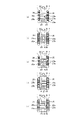
- the tops of the corrugated fins 2 are aligned in the height direction. (a) to (e) of FIG. 1 will be described later.
- FIG. 2 is a schematic perspective view of part of the heat exchanger according to Embodiment 1.
- FIG. The white arrows in FIG. 2 indicate the direction of air flow.
- FIG. 3 is a schematic cross-sectional view of the flat plate portion of the corrugated fin according to Embodiment 1 cut in the air circulation direction.
- the oblique solid line arrows in FIG. 3 indicate the flow of the condensed water.
- the corrugated fins 2 are joined to the flat surfaces 1a of the flat heat transfer tubes 1 except for the upstream protrusions 2a that protrude upstream of the flat heat transfer tubes 1 in the air circulation direction. This joint portion is brazed and joined with a brazing material.
- the material of the fin material forming the corrugated fins 2 is, for example, an aluminum alloy.
- the surface of the fin material forming the corrugated fin 2 is clad with a brazing material layer.
- the main material of the clad brazing material layer is, for example, an aluminum-silicon-based brazing material containing aluminum.
- the plate thickness of the fin material forming the corrugated fin 2 is, for example, about 50 ⁇ m to 200 ⁇ m.
- the corrugated fin 2 has a structure in which plate-like fin portions 24 are continuous in a wave shape in the pipe axial direction.
- the corrugated fin 2 has a shape in which fin portions 24 are alternately connected in the direction of the tube axis with opposite inclinations when viewed in the direction of air circulation.
- the fin portion 24 has a flat plate portion 21 and curved top portions 20 at both ends of the flat plate portion 21 in the direction in which the pipes are arranged side by side.
- the corrugated fin 2 is joined to the flat heat transfer tube 1 in surface contact with the flat surface 1a of the flat heat transfer tube 1 at the top portion 20 portion.
- a plurality of louvers 22 are formed in the fin portion 24 so as to be aligned in the air circulation direction.
- the louver 22 has a louver slit 22a that allows air to pass through, and a plate portion 22b that guides the air to the louver slit 22a.
- the plate portion 22 b is inclined with respect to the flat plate portion 21 .
- the louver slit 22a and the plate portion 22b are formed in a rectangular shape extending in the direction in which the pipes are arranged side by side.
- the louver 22 is formed by cutting and raising a plate portion 22 b from the flat plate portion 21 .
- the plurality of louvers 22 are formed in a first louver group 22A formed on the upstream side in the air circulation direction of drainage slits 23 formed in the fin portion 24, and on the downstream side in the air circulation direction of the drainage slits 23. and a second louver group 22B.
- l1 is an imaginary center auxiliary line in the thickness direction of the plate portion 22b of the first louver group 22A
- l2 is an imaginary center auxiliary line of the plate portion 22b of the second louver group 22B in the plate thickness direction.
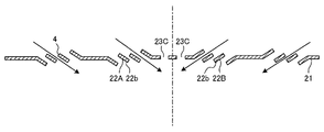
- the plate portion 22b of the first louver group 22A and the plate portion 22b of the second louver group 22B are inclined in opposite directions with respect to the flat plate portion 21. As shown in FIG. Since the plate portions 22b of the louvers 22 are formed in this direction, the condensed water flowing along the plate portions 22b of the louvers 22 formed on a certain fin portion 24 is drained from the fin portions 24 below. Water is guided toward the slit 23 . Therefore, the heat exchanger 10 having this configuration can greatly improve drainage.
- a drainage slit 23 for draining condensed water generated on the fin portion 24 is formed in the fin portion 24 .
- the drainage slits 23 are through holes formed in the corrugated fins 2 .
- the drainage slit 23 is formed in a rectangular shape extending in the direction in which the pipes are arranged side by side.
- the drainage slit 23 is formed in the central portion in the air circulation direction of the fin portion 24 excluding the upstream projecting portion 2a.
- FIG. 1 shows an example in which the drainage slits 23 are formed in two rows in the air circulation direction, but the number of rows of the drainage slits 23 may be one, or three or more.
- the regions of the fin portion 24 between the rows of the drainage slits 23 serve as heat transfer regions 503 .
- the plurality of rows of the drainage slits 23 are formed adjacent to the central portion in the air circulation direction of the fin portion 24 excluding the upstream protruding portion 2a. Adjacent to each other means that there is no louver 22 between the drainage slits 23 .
- the surface temperature of the flat heat transfer tubes 1 and the corrugated fins 2 is lower than the temperature of the air passing through the heat exchanger 10.
- moisture in the air condenses to form condensed water 4 on the surfaces of the flat heat transfer tubes 1 and the corrugated fins 2 .
- the condensed water 4 generated on the surface of the fin portion 24 of the corrugated fin 2 flows down from the drainage slit 23 to the fin portion 24 on the lower side.
- the condensed water 4 easily flows over the surface of the fin portion 24 and easily flows down through the drainage slits 23 .
- FIG. 4 is an explanatory diagram of the position of the drainage slit in the fin portion of the corrugated fin according to Embodiment 1.
- FIG. 4 Each of FIGS. 4(a) to 4(e) corresponds to the fin portion 24 at each position of (a) to (e) of FIG. That is, FIGS. 4A to 4E show fin portions 24 adjacent in the tube axial direction. 4(a) to 4(c), two rows of drainage slits 23 are formed in the direction of air flow, and two drainage slits 23 are formed in each row in the pipe arrangement direction, for a total of four drainage slits. It shows the configuration formed.
- FIGS. 4(d) to 4(e) show a configuration in which two drainage slits 23 are formed, one drainage slit 23 is formed in each row, and a total of two drainage slits are formed.
- the drainage slits 23 are arranged such that the positions of the fin portions 24 adjacent to each other in the pipe axis direction are shifted from each other in the pipe arrangement direction.
- the condensed water in the corrugated fins 2 is drained as follows.
- the flow of condensed water will be described using two vertically adjacent fin portions 24 .
- Condensed water generated on the surface of the upper fin portion 24 flows down from the drainage slit 23 of the upper fin portion 24 onto the lower fin portion 24 .
- the positions of the drainage slits 23 are shifted in the pipe arrangement direction between the fin portions 24 adjacent to each other in the pipe axial direction. Therefore, a portion of the region immediately below the drain slit 23 in the upper fin portion 24 is a portion in which the drain slit 23 is not formed in the lower fin portion 24, and the condensed water is generated and held. is. Therefore, the condensed water 4 falling from the drain slit 23 of the upper fin part 24 onto the lower fin part 24 joins the condensed water 4 held on the surface of the lower fin part 24 and becoming difficult to flow.
- the condensed water 4 which has increased in amount due to the confluence, flows down easily and is drained through the drain slits 23 of the fin portions 24 on the lower side.
- the flow of condensed water described above is sequentially repeated in the vertical direction between the two fin portions 24 adjacent to each other in the direction of the tube axis. Good drainage is provided.
- the drainage slits 23 are formed overlapping the apexes 20 at both ends of the flat plate portion 21 in the pipe arrangement direction when viewed in the pipe axial direction.
- the drainage slit 24 is formed so as to overlap the top portion 20 at one end of the flat plate portion 21 in the direction in which the pipes are arranged side by side, as viewed in the pipe axial direction.
- a drainage top portion 20a the portion of the fin portion 24 where the drainage slit 23 overlaps the top portion 20 is referred to as a drainage top portion 20a, and the portion of the fin portion 24 where the drainage slit 23 does not overlap the top portion 20 is referred to as a non-drainage top portion 20b for convenience of explanation. .
- FIG. 4(d) there are two rows of drainage slits 23, and one drainage slit 23 in each row overlaps the top portion 20 on one end side (right side in FIG. 4) of the fin portion 24 in the pipe arrangement direction. For this reason, the fin portion 24 of FIG. 4(d) has two drainage top portions 20a. In FIG. 4(d), one drainage slit 23 does not overlap in each row on the top portion 20 on the other end side (left side in FIG. 4) of the fin portion 24 in the direction in which the pipes are arranged side by side. For this reason, the fin portion 24 of FIG. 4(d) has two non-drainage top portions 20b.
- FIG. 4(e) there are two rows of drainage slits 23, and one drainage slit 23 in each row overlaps the top portion 20 on the other end side (left side in FIG. 4) of the fin portion 24 in the pipe arrangement direction. .
- the fin portion 24 of FIG. 4(e) has two drainage top portions 20a.
- one drain slit 23 in each row does not overlap the top portion 20 on one end side (right side in FIG. 4) of the fin portion 24 in the direction in which the pipes are arranged side by side.
- the fin portion 24 of FIG. 4(d) has two non-drainage top portions 20b.
- the top portion 20 is a portion formed by bending a flat fin material into a V shape, the inner space of the top portion 20 is narrow (see FIG. 6 described later). Therefore, the condensed water 4 generated on the inner surface of the top portion 20 is likely to be held and stay in the inner space of the top portion 20 by the surface tension generated in the condensed water 4 . Therefore, since the top part 20 has the drainage top part 20a, it is possible to prevent the condensed water from remaining in the inner space of the top part 20, thereby improving the drainage performance. As the number of the drainage top portions 20a is increased, the effect of improving the drainage performance is obtained. Increasing the number of the top portions 20a leads to deterioration in heat transfer.
- the ratio between the number of drained top portions 20a and the number of non-drained top portions 20b should be determined in consideration of drainage and heat transfer. Moreover, if the number of the drainage top portions 20a is increased, the number of joints between the fin portions 24 and the flat heat transfer tubes 1 is reduced, resulting in a decrease in strength. For this reason, it is desirable that the corrugated fin 2 as a whole have a well-balanced distribution of the drained top portions 20a and the non-drained top portions 20b.
- FIG. 4 shows an example in which the drainage slits 23 are formed at positions overlapping the top portions 20 at both ends of the flat plate portion 21 in the direction in which the pipes are arranged side by side when viewed in the pipe axial direction. You may
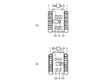
- FIG. 5 is a diagram showing a modification of the heat exchanger according to Embodiment 1.
- FIG. 5(a) shows the upper fin portion 24 among the fin portions 24 adjacent in the tube axial direction
- FIG. 5(b) shows the lower fin portion 24 among the fin portions 24 adjacent in the tube axial direction.
- FIG. 6 is an explanatory diagram of the flow of condensed water in the configuration of FIG.
- the drainage slits 23 are formed at positions that do not overlap the top portions 20 at both ends of the flat plate portion 21 in the direction in which the pipes are arranged side by side when viewed in the pipe axial direction.
- the upper fin portion 24A of the two fin portions 24 forming the top portion 20 surrounded by the dotted line circle corresponds to the fin portion 24 in FIG. It corresponds to the fin portion 24 of 5(b).
- the drainage slit 23 is arranged so as not to overlap the top portion 20 when viewed in the pipe axis direction, so the top portion 20 between the fin portion 24A and the fin portion 24B is the non-drainage top portion 20b. It's becoming Therefore, the surface tension generated in the condensed water 4 makes it easier for the condensed water to stay in the inner space of the non-drainage top portion 20b.
- the portion where the condensed water 4 stays is hereinafter referred to as a top staying portion 30 . Drainage of the condensed water 4 retained in the top retaining portion 30 will be described below.
- the condensed water generated and collected on the surface of the fin portion 24C above the fin portion 24A flows down toward the fin portion 24A from the drainage slits 23 of the fin portion 24C.
- the drainage slit 23 of the fin portion 24C and the drainage slit 23 of the fin portion 24A are formed so as to be shifted in the pipe arrangement direction (horizontal direction in FIG. 6).
- the condensed water 4 flowing down from the end of the drain slit 23 of the fin portion 24C in the pipe arrangement direction (here, the left end in FIG. 6) passes through the drain slit 23 of the fin portion 24A and stays at the top. It merges with the condensed water 4 staying in the part 30 .
- the condensed water 4 in the top retaining portion 30 breaks the surface tension and flows out of the top retaining portion 30 and flows on the surface of the fin portion 24B as indicated by the dotted line arrow in FIG. In this manner, even in the fin portion 24 in which the drainage slit 23 is formed at a position not overlapping the top portion 20 when viewed in the tube axial direction, the drainage performance can be improved.
- FIG. 7 is a diagram showing an example of analysis results of drainage characteristics according to the number of rows of drainage slits.
- the vertical axis in FIG. 7 indicates the residual water content of the heat exchanger, and the horizontal axis indicates time. The faster the rate of decrease of the residual water content, the higher the drainage performance. Drainability is the amount of water discharged per unit time. Drainage measurement is generally performed as follows. An experimental model heat exchanger having fins with one row, two rows, and three rows of drain slits 23 having the same opening area is fabricated. Then, each heat exchanger is immersed in a water tank and taken out, and the amount of residual water remaining in each heat exchanger is measured over time.
- FIG. 7 summarizes an example of the calculation results of simulating the above test evaluation using the three-dimensional analysis of the gas-liquid two-phase flow developed by the inventors.
- the drainage performance when two drainage slits 23 are provided and when one drainage slit 23 having the total opening area of the two drainage slits 23 is provided it was found that the case where two drainage slits 23 are provided can improve the drainage performance.
- the mechanism of this drainage improvement was found to be as follows. Even if the opening area of the drainage slit 23 is increased, the vicinity of the center of the drainage slit 23 does not contribute to drainage. Therefore, even if the opening area of the drain slit 23 is increased, the effect of improving the drainability is small, and on the other hand, the deterioration in performance due to the decrease in the heat transfer area increases.
- the heat exchanger 10 can improve drainage performance, suppressing deterioration in heat transfer performance.
- the heat exchanger 10 has a plurality of rows of drainage slits 23 between the first louver group 22A and the second louver group 22B, thereby maintaining the heat transfer performance and improving the drainage performance.
- FIG. 8 is a diagram showing an example of a graph showing the relationship between the ratio of the ventilation cross-sectional area AL between the louvers and the drainage slit opening area As, and the drainage performance. Drainage is the amount of water discharged per unit time, and the higher the drainage, the more water is discharged per unit time.
- a graph of analysis results showing the relationship when the drainage performance is defined as 100% when the ratio of the inter-louver cross-sectional area AL to the drainage slit opening area As is 0.25 is shown. Similar to the case of FIG. 7, this analysis result summarizes an example of calculation results obtained by immersing the heat exchangers in a water tank and taking them out, and calculating the amount of residual water remaining in each heat exchanger at an arbitrary time.
- FIG. 7 shows an example of calculation results obtained by immersing the heat exchangers in a water tank and taking them out, and calculating the amount of residual water remaining in each heat exchanger at an arbitrary time.
- FIG. 9 is a diagram showing the dimensions of each part used for explaining the relationship of FIG. 8, and is a schematic plan view of a part of the heat exchanger.
- FIG. 10 is a schematic cross-sectional view of the fin section cut in the air circulation direction, which is an explanatory diagram of the dimensions of each part used for explaining the relationship of FIG.
- the drainage speed is greatly affected by the ratio of the inter-louver cross-sectional area AL and the drainage slit opening area As.
- the drainage slit opening area As is defined by Ns ⁇ Sw ⁇ Ss.
- the louver-to-louver ventilation cross-sectional area AL is constant, the more the drainage slit opening area As is increased, the more the drainage speed is improved. Therefore, by providing a plurality of rows of drainage slits 23 to increase the drainage slit opening area As, the drainage speed can be increased.
- the heat transfer performance can be improved when the length hs of the heat transfer region 503 in the air circulation direction is shorter than the length Ss of the drain slit 23 in the air circulation direction.
- the drainage performance is improved as described below. can.
- the distance between the drain slits 23 adjacent to each other in the air circulation direction becomes closer, the water droplets falling from the respective drain slits 23 are combined to become one large water droplet and fall. That is, the two narrow drainage slits 23 function like one wide slit. Therefore, it is considered that the effect of improving the drainage property is greater when the length hs of the heat transfer region 503 in the air circulation direction is shorter than the length Ss of the drainage slit 23 in the air circulation direction.
- the length hs of the heat transfer area 503 in the air circulation direction is longer than the length Ss of the drain slit 23 in the air circulation direction, there is an advantage of increased strength, but condensed water tends to remain on the heat transfer area 503 . , and the water droplets fall separately from the drainage slits 23 . Therefore, if the length hs of the heat transfer region 503 in the air circulation direction is longer than the length Ss of the drainage slit 23 in the air circulation direction, it is considered that the effect of improving the drainage performance is small.
- the heat transfer regions 503 and the drainage slits 23 alternately exist in the air circulation direction. From a different point of view, this configuration is divided into a plurality of large holes by a thin bridge extending in the pipe arrangement direction (horizontal direction in FIG. 9) in the middle of the air circulation direction of one large hole. configuration. This bridge corresponds to the heat transfer area 503 . As a mechanism for improving the drainage performance, it is considered that by providing the heat transfer region 503 corresponding to a thin bridge, water is easily guided to the center between the two drainage slits 23 by traveling through the heat transfer region 503 .
- a heat exchanger in which the length hs of the heat transfer region 503 in the air circulation direction is shorter than the length Ss of the drainage slit 23 in the air circulation direction can improve drainage while maintaining heat transfer.
- the heat transfer region 503 functions as a retainer that suppresses warping deformation of the fin material that occurs when the drainage slit 23 is drilled in the fin material. This point will be described using a comparative corrugated fin that does not include the heat transfer region 503 .
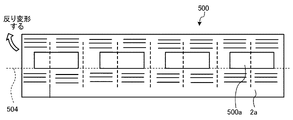
- FIG. 11 is an explanatory diagram of warp deformation of a corrugated fin of a comparative example during hole punching.
- FIG. 11 shows the fin material before corrugating. Dotted lines extending in the vertical direction in FIG. 11 indicate boundary lines between fin portions.
- the fin material 500 of the comparative example does not have the heat transfer region 503 and has one large opening 500a that serves as a drainage slit.
- the opening 500a is arranged at the center of the fin material 500 in the air circulation direction, excluding the upstream projecting portion 2a. Therefore, the opening 500a is located at a position offset with respect to the center line 504 of the fin material 500 in the air circulation direction.
- the opening 500a is at a biased position in this manner, a moment is generated on the biased side (the upper side in FIG. 11), and the fin material 500 is warped and deformed.
- the corrugated fin 2 of Embodiment 1 corresponds to a configuration in which the large opening 500a, which was one in the comparative example, is divided into a plurality of small openings.
- heat transfer regions 503 are formed between small openings.
- portions of the fin material that are not holes are formed between the small openings. Therefore, this fin material portion works as a retainer for suppressing warpage deformation, and the corrugated fin 2 of Embodiment 1 can improve warpage deformation.
- FIG. 12 is a diagram showing an example of analysis results of drainage characteristics according to louver angles.
- the vertical axis in FIG. 12 indicates the residual water content of the heat exchanger, and the horizontal axis indicates time. The faster the rate of decrease of the residual water content, the higher the drainage performance.
- This analysis is performed as follows. Fins with louvers with a louver angle of 15° Fins with louvers with a louver angle of 20° Fins with louvers with a louver angle of 30° Fins with louvers with a louver angle of 40° Create a computational model of a heat exchanger having a section.
- louver angle As shown in Fig. 12, it can be seen that as the louver angle increases, the speed of reduction of the residual water content increases and the drainage performance increases. This is probably because as the louver angle increases, the drainage effect due to gravity increases, and the surface tension of the condensed water generated on the surface of the louver 22 is easily broken. As the louver angle increases, the speed of reduction of the residual water content increases, but the degree of increase becomes relatively small when the louver angle exceeds 30°. Further, when the louver angle increases, the ventilation resistance at the plate portion 22b of the louver 22 increases, making it difficult for air to flow. Therefore, considering both the improvement of drainage and the ease of air flow, it is preferable to set the louver angle to 15° to 30°.
- the corrugated fin 2 preferably has a configuration in which the drained top portion 20a and the non-drained top portion 20b are mixed in a well-balanced manner.
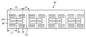
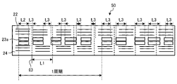
- the drainage slits 23 may be processed in the following arrangement in the fin material before corrugating. Four patterns of arrangement of the drainage slits 23 with respect to the fin material will be described below with reference to FIGS. 13 to 16 below. 13 to 16 below show flat fin stocks before corrugating. 13 to 16, the dotted line extending in the vertical direction indicates the boundary line l3 between the fin portions.
- FIG. 13 is an explanatory diagram of arrangement pattern 1 of drainage slit openings in the corrugated fin according to the first embodiment. is a diagram showing a fin material.
- the width L2 of the opening 23a that serves as the drainage slit 23 is longer than the length L1 of the fin portion 24 in the direction in which the pipes are arranged side by side.
- the intervals between the openings 23a of the adjacent fin portions 24 are equal. That is, the length L3 of this interval is the same at each position of the fin material 50 in the longitudinal direction.
- the opening 23a is arranged so as to straddle the boundary line l3.
- the drain top 20a and the non-drainage top 20b are well balanced. Mixed configurations can be formed.
- FIG. 1 the width L2 of the opening 23a that becomes the drainage slit 23 is shorter than the length L1 of the fin portion 24 in the pipe arrangement direction.
- the intervals between the openings 23a of the adjacent fin portions 24 are equal.
- the length L3 of this interval is the same at each position in the longitudinal direction of the fin material 50 . Note that the length L3 takes a value other than the value obtained by subtracting L2 from L1.
- the drained top portion 20a and the non-drained top portion 20b are not mixed, and all the top portions 20 may be the drained top portion 20a or the non-drained top portion 20b. be.
- the openings 23a to be drainage slits in the fin material 50 before corrugating with the above size and arrangement, in the corrugated fin 2 after corrugating, the drained top portion 20a and the non-drained top portion 20b are mixed in a well-balanced manner. configuration can be formed.
- FIG. 15 is an explanatory diagram of arrangement pattern 3 of the drainage slit openings in the corrugated fin according to the first embodiment.
- the width L2 of the opening 23a that serves as the drainage slit 23 is shorter than the length L1 of the fin portion 24 in the pipe arrangement direction.
- the intervals between the openings 23a of the adjacent fin portions 24 are not equal. That is, the length L3 of this interval differs at each position in the longitudinal direction of the fin material 50 .
- the pattern 3 has a configuration in which an arrangement pattern having five openings 23a in the longitudinal direction of the fin material 50 is defined as one cycle, and this arrangement pattern is periodically repeated in the longitudinal direction of the fin material 50. As shown in FIG.
- the corrugated fin 2 after corrugating has a well-balanced mixture of the drained top 20a and the non-drained top 20b.
- L3 By adjusting L3, it is possible to adjust the ratio of the drained top portion 20a and the non-drained top portion 20b in one corrugated fin 2, so that the drainage performance and the heat transfer performance can be balanced based on the design. .
- FIG. 16 is an explanatory diagram of the arrangement pattern 4 of the drainage slit openings in the corrugated fin according to the first embodiment.
- the width L2 of the opening 23a that becomes the drainage slit 23 is different at each position.
- the intervals between the openings 23a of the adjacent fin portions 24 are equal.
- the length L3 of this interval is the same at each position in the longitudinal direction of the fin material 50 .
- the pattern 4 has a configuration in which an arrangement pattern having five openings 23 a in the longitudinal direction of the fin material 50 is defined as one period, and this arrangement pattern is periodically repeated in the longitudinal direction of the fin material 50 .
- the corrugated fin 2 after corrugating has a well-balanced mixture of the drained top 20a and the non-drained top 20b.
- L2 the proportion of the drained top portion 20a and the non-drained top portion 20b in one corrugated fin 2 can be adjusted, so that the drainage performance and the heat transfer performance can be balanced based on the design. .
- the fin members 50 of the arrangement patterns 1 to 4 described above all have a configuration in which a specific arrangement pattern is periodically repeated in the longitudinal direction of the fin members 50 .
- the fin portions 24 having the same position in the direction in which the drainage slits 23 are arranged in parallel with the pipe are separated from each other by several fin portions in the pipe axial direction. It is a structure that appears repeatedly repeatedly in With this configuration, the heat exchanger 10 can have a well-balanced mixture of the drained top portion 20a and the non-drained top portion 20b. As a result, it is possible to obtain the heat exchanger 10 with improved drainage performance while maintaining heat transfer performance.
- Drainage slit 23 drilling process When a specific arrangement pattern is periodically repeated in the longitudinal direction of the fin material 50, such as the arrangement patterns 1 to 4, the drainage slits 23 are processed using a corrugated cutter or a corrugated perforating roller. can be done.
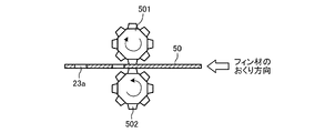
- FIG. 17 shows a state of drilling using a corrugated cutter.
- FIG. 17 is an explanatory diagram of the drilling process of the drainage slit by the corrugated cutter.
- a pair of corrugated cutters 501 and 502 are arranged facing each other, and the fin material 50 is arranged between the pair of corrugated cutters 501 and 502 .
- a pair of corrugated cutters 501 and 502 are rotated in the direction of the solid line arrow by feeding the fin material 50 in the direction of the white arrow, and cut the opening 23a which becomes the drainage slit 23 in the fin material 50 while rotating. conduct.
- the processing speed when manufacturing the corrugated fins 2 can be increased. If the arrangement pattern is not periodically repeated, manufacturing using the corrugated cutter cannot be performed, but the present disclosure is not limited to the arrangement pattern that is periodically repeated.
- the heat exchanger 10 of Embodiment 1 has a flattened cross section, has a plurality of flow paths formed of through holes, and is spaced apart in the direction perpendicular to the air circulation direction.
- the heat exchanger includes a plurality of flat heat transfer tubes 1 arranged side by side and corrugated fins 2 arranged between the plurality of flat heat transfer tubes 1 .
- the corrugated fin 2 has a configuration in which plate-like fin portions 24 are connected in a wave shape in the tube axis direction of the plurality of flat heat transfer tubes 1 .
- the fin portion 24 has a drain slit 23 extending in the direction in which the flat heat transfer tubes 1 are arranged side by side, and a louver slit 22a extending in the direction in which the tubes are arranged side by side. and a plurality of louvers 22 having inclined plate portions 22b.
- the plurality of louvers 22 are divided into a first louver group 22A formed upstream of the drainage slit 23 in the air circulation direction and a second louver group 22B formed downstream of the drainage slit 23 in the air circulation direction. divided.
- the plate portion 22b of the first louver group 22A and the plate portion 22b of the second louver group 22B are inclined in opposite directions with respect to the flat plate portion 21.
- the heat exchanger 10 has a plurality of rows of drainage slits 23 between the first louver group 22A and the second louver group 22B.
- the heat exchanger 10 of Embodiment 1 can improve drainage while maintaining heat transfer.
- the heat exchanger 10 of Embodiment 1 can improve drainage while maintaining heat transfer.
- a plurality of rows of drainage slits 23 are formed adjacent to each other in the air circulation direction.
- the length hs in the air circulation direction of the heat transfer region 503, which is the region of the fin portion 24 sandwiched in the air circulation direction by the drainage slits 23 provided in a plurality of rows, is shorter than the length Ss of the drainage slits 23 in the air circulation direction. .
- the heat exchanger 10 of Embodiment 1 can improve drainage while maintaining heat transfer.
- the angle of the plate portion 22b of each of the plurality of louvers 22 with respect to the flat plate portion 21 is 15° to 30°.
- the heat exchanger 10 of Embodiment 1 can achieve both improved drainage and ease of air flow.
- the fin portion 24 has top portions 20 that are joined to the plurality of flat heat transfer tubes 1 at both end portions of the flat plate portion 21 in the pipe arrangement direction. Some of the plurality of fin portions 24 are formed with drainage slits 23 at positions overlapping one or both of the top portions 20 at both end portions when viewed in the tube axial direction. Some of the plurality of fin portions 24 are formed with drainage slits 23 at positions that do not overlap with both the top portions 20 at both ends when viewed in the pipe axial direction.
- the heat exchanger 10 of Embodiment 1 can balance drainage and heat transfer performance based on the design.
- the positions of the drainage slits 23 in the direction in which the pipes are arranged are shifted between the fin portions adjacent to each other in the pipe axial direction.
- the heat exchanger 10 of Embodiment 1 can improve drainage.
- the corrugated fin 2 has a structure in which the fin portions 24 having the same position in the air circulation direction of the drainage slit 23 appear periodically and repeatedly in the pipe axis direction.
- Embodiment 2 relates to a configuration in which a plurality of heat exchangers 10 of Embodiment 1 are provided in the air circulation direction.
- the second embodiment will be described with a focus on the differences from the first embodiment, and the configurations not described in the second embodiment are the same as those in the first embodiment.
- FIG. 18 is a schematic plan view showing an enlarged part of the heat exchanger according to Embodiment 2.
- FIG. 19 is a diagram showing an arrangement pattern of drainage slit openings in the corrugated fins of the heat exchanger of FIG. 18.
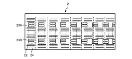
- FIG. A heat exchanger 10A according to Embodiment 2 has a configuration in which a plurality of flat heat transfer tubes 1 are arranged in two rows at intervals in the air circulation direction, and corrugated fins 2 are arranged in common in the two rows.
- the flat heat transfer tube 1 on the windward side is referred to as a flat heat transfer tube 1A
- the flat heat transfer tube 1 on the leeward side is referred to as a flat heat transfer tube 1B.
- the longitudinal dimension L4 of the flat cross section of the flat heat transfer tube 1A and the longitudinal dimension L5 of the flat cross section of the flat heat transfer tube 1B may be the same or different.
- the flat heat transfer tubes 1 are arranged in two rows here, they may be arranged in three or more rows.
- the corrugated fins 2 of the heat exchanger 10A according to Embodiment 2 are arranged in common to the flat heat transfer tubes 1A and 1B, and are brazed and joined to the flat heat transfer tubes 1A and 1B.
- the corrugated fin 2 has louvers 22 and drainage slits 23 corresponding to each row.
- the first drainage slit 23A which is the drainage slit 23 on the windward side, is formed within a range corresponding to the longitudinal length of the flat cross section of the flat heat transfer tube 1A.
- the plurality of louvers 22 on the windward side are composed of a first louver group 22A formed upstream in the air circulation direction of the first drainage slit 23A and a second louver group 22A formed downstream of the drainage slit 23 in the air circulation direction. Louver group 22B and .
- the plate portion 22b of the first louver group 22A and the plate portion 22b of the second louver group 22B are inclined in opposite directions with respect to the flat plate portion 21. As shown in FIG.
- the second drainage slit 23B which is the drainage slit 23 on the leeward side, is formed within a range corresponding to the longitudinal length of the flat cross section of the flat heat transfer tube 1B.
- the plurality of louvers 22 on the leeward side are a first louver group 22A formed upstream of the second drainage slit 23B in the air circulation direction, and formed downstream of the second drainage slit 23B in the air circulation direction. It is divided into a second louver group 22B and a second louver group 22B.
- the plate portion 22b of the first louver group 22A and the plate portion 22b of the second louver group 22B are inclined in opposite directions with respect to the flat plate portion 21. As shown in FIG.
- each of the first drainage slits 23A and the second drainage slits 23B is formed in two rows in the air circulation direction, and two rows are formed in each row in the pipe arrangement direction.
- can't 18 and 19 the positions of the first drainage slit 23A and the second drainage slit 23B in the fin portion 24 are the same in the pipe arrangement direction, but they are different as shown in FIGS. 20 and 21 below. You can let
- FIG. 20 is a schematic plan view showing an enlarged part of a modification of the heat exchanger according to Embodiment 2.
- FIG. 21 is a diagram showing an arrangement pattern of drainage slit openings in the corrugated fins of the heat exchanger of FIG. 19.
- FIG. 10A of this modified example the positions of the first drainage slit 23A and the second drainage slit 23B in the fin portion 24 in the pipe arrangement direction are different.
- the drainage performance and the heat transfer performance can be individually adjusted on the windward side and the leeward side.
- the drainage performance can be improved by adjusting the position of the drainage slit 23 to increase the number of the drainage tops 20a, and the heat transfer can be improved by reducing the number of the drainage tops 20a.
- the drainage performance can be improved by increasing the width of the drainage slit 23, and the heat transfer performance can be improved by decreasing the width of the drainage slit 23.
- the heat exchanger 10A when the heat exchanger 10A is used as an evaporator, since the windward side has higher heat transfer performance than the leeward side, condensed water is likely to occur on the windward side. Therefore, drainage is required on the windward side.
- the leeward side has lower heat transfer performance than the windward side and less condensed water is generated, so heat transfer performance is required more than drainage. That is, when the heat exchanger 10A is used as an evaporator, it is required to prioritize drainage on the windward side and heat transfer on the leeward side.
- the position of the drainage slit 23 should be adjusted as follows. That is, in one corrugated fin 2, the number of drainage top portions 20a on the windward side is defined as N, and the number of drainage top portions 20a on the leeward side is defined as M. In this case, the positions of the first drainage slit 23A and the second drainage slit 23B are adjusted so as to satisfy N>M. As a result, a heat exchanger can be constructed in which priority is given to drainage on the windward side and heat transfer to the leeward side.
- the total drainage slit width of the plurality of first drainage slits 23A on the windward side is defined as Sw F
- the total drainage slit width of the plurality of second drainage slits 23B on the leeward side is defined as Sw B. do.
- the structure satisfies the relationship of Sw F >Sw B.
- a heat exchanger can be constructed in which priority is given to drainage on the windward side and heat transfer to the leeward side.
- the heat exchanger 10A By configuring the heat exchanger 10A with heat transfer priority on the leeward side in this way, the difference in heat transfer performance between the windward side and the leeward side can be reduced. By reducing the difference in heat transfer performance between the windward side and the leeward side, the thickness of the frost that forms on the surface of the fins can be made uniform under low-temperature air conditions. By making the thickness of the frost that forms on the surface of the fins closer to uniformity, the heat exchange performance is improved in low-temperature air conditions.
- a heat exchanger 10A of Embodiment 2 has a configuration in which a plurality of flat heat transfer tubes 1 arranged in the tube parallel direction are arranged in multiple rows at intervals in the air circulation direction, and corrugated fins 2 are arranged in common in the multiple rows. have With this configuration, by adjusting one or both of the positions of the first drainage slits 23A and the second drainage slits 23B in each row and the width of the drainage slits, drainage performance and heat transfer performance can be improved on the windward side and the leeward side. Adjustable. Thereby, the heat exchanger 10A of Embodiment 2 can improve the heat exchange performance under low-temperature air conditions.
- Embodiment 3 relates to a configuration in which an inter-row drainage slit is further formed in the heat exchanger 10A of the second embodiment.
- the following description focuses on the differences of the third embodiment from the second embodiment, and the configurations not described in the third embodiment are the same as those of the second embodiment.
- FIG. 22 is a schematic plan view showing an enlarged part of the heat exchanger according to Embodiment 3.
- FIG. In the heat exchanger 10B according to Embodiment 3, the flat plate portion 21 between the flat heat transfer tubes 1A and 1B has an inter-row drainage slit 23C in the non-joining region 21a that is not joined to the flat heat transfer tubes 1. It has a formed configuration.
- the inter-row drainage slits 23 are through holes formed in the corrugated fins 2 .
- FIG. 22 shows an example in which the inter-row drainage slits 23C are formed in two rows in the air circulation direction, but the inter-row drainage slits 23C may be formed in one row or in three or more rows.
- the positions of the drain slits 23C between the two rows are aligned in the direction in which the pipes are arranged side by side, but the positions may be shifted as shown in FIG.
- FIG. 23 is a schematic plan view showing an enlarged part of a modification of the heat exchanger according to Embodiment 3.
- FIG. 10B of this modified example the positions of the two rows of inter-row drainage slits 23C are shifted in the pipe arrangement direction.
- FIG. 24 is a sectional view taken along line AA of FIGS. 22 and 23.
- FIG. A dashed line in FIG. 24 is a center line indicating the central position of the inter-row drainage slits 23C formed in two rows in the air circulation direction. Arrows in FIG. 24 indicate the flow of condensed water during drainage.
- Heat exchanger 10B of Embodiment 3 uses inter-row drainage slit 23C as a main drainage slit. Therefore, the drainage slit for dividing the plurality of louvers 22 into the first louver group 22A and the second louver group 22B is the row-to-row drainage slit 23C.
- the first louver group 22A is the louver group upstream in the air circulation direction of the inter-row drainage slit 23C
- the second louver group 22B is the louver group downstream in the air circulation direction of the inter-row drainage slit 23C. be.
- the plate portion 22b of the first louver group 22A and the plate portion 22b of the second louver group 22B are inclined in opposite directions with respect to the flat plate portion 21. As shown in FIG. With such a configuration, the condensed water flowing along the plate portion 22b of the louver 22 is guided toward the inter-row drainage slits 23C of the lower fin portion 24, thereby improving the drainage performance.
- the opening area of the inter-row drainage slit 23C is configured to be larger than the opening area of each of the first drainage slit 23A and the second drainage slit 23B. In this configuration, the condensed water is guided toward the inter-row drainage slit 23C. Therefore, by making the opening area of the inter-row drainage slit 23C larger than the opening areas of the first drainage slit 23A and the second drainage slit 23B, drainage performance can be improved compared to the case where the opening areas are the same. From the viewpoint of improving drainage performance, it is preferable that the opening area of the inter-row drainage slit 23C is larger than the opening areas of the first drainage slit 23A and the second drainage slit 23B, but the opening areas may be the same.
- the inter-row drainage slits 23C may be arranged in a single row, but if they are arranged in a plurality of rows, the effect of improving the drainage property is increased, which is even better.
- the positions of the first drainage slit 23A, the second drainage slit 23B, and the inter-row drainage slit 23C in the pipe arrangement direction may be shifted from each other, or may be aligned.
- FIG. 22 By the way, comparing the configuration of FIG. 22 and the configuration of FIG. 23, the configuration of FIG. Smaller than configuration. 22 and 23, the shaded portion of dots is the heat transfer area 503.
- FIG. 23 Since the heat transfer region 503 is formed between the inter-row drainage slits 23C, it can be said that the strength of the heat transfer region 503 is weak. In the configuration of FIG. 23, the area of this weak portion can be made smaller than in FIG. 23, so a heat exchanger with stronger fins than in the configuration of FIG. 22 can be constructed.
- the same effects as those of the second embodiment can be obtained, and the inter-row airflow direction is provided between the flat heat transfer tubes 1 of each row corresponding to the air circulation direction. Since the drainage slit 23C is formed, the drainage performance can be improved.
- the plate portion 22b of the first louver group 22A on the upstream side in the air circulation direction of the inter-row drainage slit 23C and the plate portion 22b of the second louver group 22B on the downstream side in the air circulation direction of the inter-row drainage slit 23C are inclined in opposite directions to each other with respect to the flat plate portion 21 .
- the condensed water is guided toward the inter-row drainage slit 23C, and drainage can be improved.
- the opening area of the inter-row drainage slit 23C is larger than the opening area of each of the first drainage slit 23A and the second drainage slit 23B, which are drainage slits other than the inter-row drainage slit, the opening area is the same. can also improve drainage.
- Embodiment 4 the upstream protruding portion 2a of the fin portion 24 in the heat exchanger 10B of the third embodiment is thickened.
- the following description focuses on the differences of the fourth embodiment from the third embodiment, and the configurations not described in the fourth embodiment are the same as those of the third embodiment.
- FIG. 25 is a schematic plan view showing an enlarged part of the heat exchanger according to the fourth embodiment.
- 26 is a cross-sectional view taken along the line BB of FIG. 25.
- the plate thickness of the upstream protrusions 2a of the corrugated fins 2 is thicker than the portions of the corrugated fins 2 other than the upstream protrusions 2a.
- the upstream protruding portion 2a is formed thick by folding back the fin portion 24 protruding upstream from the flat heat transfer tube 1 .
- the upstream protruding portion 2a of the corrugated fin 2 is made thicker than the portions other than the upstream protruding portion 2a. Therefore, the strength of the upstream projecting portion 2a can be ensured, and deformation of the upstream projecting portion 2a when frost adheres can be suppressed.
- the heat exchanger 10C according to the fourth embodiment can obtain the same effect as the third embodiment, and the upstream protruding portion 2a of the corrugated fin 2 is set further than the portion other than the upstream protruding portion 2a. Since it is made thick, the following effects are obtained. That is, the strength of the upstream projecting portion 2a can be improved, and deformation of the upstream projecting portion 2a when frost adheres to the upstream projecting portion 2a can be suppressed. If the upstream projecting portion 2a were to deform, the air flow path would be obstructed, resulting in a decrease in the heat exchange capacity. maintain exchange capacity.
- the upstream protruding portion 2a has a thicker wall thickness by folding back the fin portion protruding upstream from the flat heat transfer tube 1 . Therefore, the thick upstream projecting portion 2a can be easily formed. From the viewpoint of ensuring the strength of the upstream protruding portion 2a, a method of increasing the thickness of the entire corrugated fin is also conceivable. However, when this method is adopted, the thickness of the plate portion 22b of the louver 22 also increases, so that the cross-sectional area of ventilation between the louvers becomes small, and the drainage of condensed water from between the louvers decreases. In contrast, in the heat exchanger 10C of Embodiment 4, only the upstream projecting portion 2a is thickened. Therefore, the heat exchanger 10C of the fourth embodiment can improve the strength of the upstream protruding portion 2a without deteriorating the drainage performance.
- the upstream projecting portion 2a of the flat plate portion 21 is configured to be thick, but in the heat exchanger of Embodiment 1 or 2, , the upstream protruding portion 2a of the flat plate portion 21 may be configured to be thick.
- Embodiment 5 relates to an air conditioner as an example of a refrigeration cycle apparatus including the heat exchangers of Embodiments 1 to 4.
- FIG. 5 is a diagrammatic representation of Embodiments 1 to 4.
- FIG. 27 is a diagram showing a configuration of an air conditioner according to Embodiment 5.
- the air conditioner uses the heat exchangers of Embodiments 1 to 4 as the outdoor heat exchanger 230 .
- the heat exchangers of Embodiments 1 to 4 may be used as indoor heat exchanger 110, and both outdoor heat exchanger 230 and indoor heat exchanger 110 may be used.
- the air conditioner configures a refrigerant circuit by connecting the outdoor unit 200 and the indoor unit 100 with gas refrigerant piping 300 and liquid refrigerant piping 400 .
- the outdoor unit 200 has a compressor 210 , a four-way valve 220 , an outdoor heat exchanger 230 and an outdoor fan 240 .
- one outdoor unit 200 and one indoor unit 100 are pipe-connected, but the number of units is arbitrary.
- the compressor 210 compresses and discharges the sucked refrigerant.
- compressor 210 can change the capacity of compressor 210 by arbitrarily changing the operating frequency, for example, by an inverter circuit.
- the four-way valve 220 is a valve that switches the flow of refrigerant depending on whether the air conditioner is in cooling operation or in heating operation.
- Outdoor heat exchanger 230 exchanges heat between the refrigerant and the outdoor air.
- Outdoor heat exchanger 230 functions as an evaporator during heating operation to evaporate and vaporize the refrigerant.
- outdoor heat exchanger 230 functions as a condenser during cooling operation, and condenses and liquefies the refrigerant.
- the outdoor fan 240 sends outdoor air to the outdoor heat exchanger 230 to facilitate heat exchange in the outdoor heat exchanger 230 .
- the indoor unit 100 has an indoor heat exchanger 110, a decompression device 120 and an indoor fan .
- the indoor heat exchanger 110 exchanges heat between the indoor air to be air-conditioned and the refrigerant.
- Indoor heat exchanger 110 functions as a condenser during heating operation to condense and liquefy the refrigerant. Further, indoor heat exchanger 110 functions as an evaporator during cooling operation to evaporate and vaporize the refrigerant.
- the decompression device 120 decompresses and expands the refrigerant.
- Decompression device 120 is composed of, for example, an electronic expansion valve.
- the pressure reducing device 120 adjusts the degree of opening based on instructions from a control device (not shown) or the like.
- the indoor fan 130 allows indoor air to pass through the indoor heat exchanger 110 and supplies the air that has passed through the indoor heat exchanger 110 indoors.
- each device of the air conditioner will be explained based on the flow of the refrigerant.
- the heating operation will be explained.
- the four-way valve 220 is switched to the dotted line side in FIG.
- the high-temperature and high-pressure gas refrigerant compressed and discharged by the compressor 210 passes through the four-way valve 220 and flows into the indoor heat exchanger 110 .
- the gas refrigerant that has flowed into the indoor heat exchanger 110 is condensed and liquefied by exchanging heat with the air in the air-conditioned space.
- the liquefied refrigerant flows into the outdoor heat exchanger 230 after being decompressed by the decompression device 120 into a gas-liquid two-phase state.
- the refrigerant that has flowed into the outdoor heat exchanger 230 evaporates and gasifies by exchanging heat with the outdoor air sent from the outdoor fan 240 .
- the gasified refrigerant passes through the four-way valve 220 and is sucked into the compressor 210 again.
- the air conditioner performs air conditioning for heating.
- the four-way valve 220 is switched to the solid line side in FIG.
- the high-temperature and high-pressure gas refrigerant compressed and discharged by the compressor 210 passes through the four-way valve 220 and flows into the outdoor heat exchanger 230 .
- the gas refrigerant that has flowed into the outdoor heat exchanger 230 is condensed and liquefied by exchanging heat with the outdoor air supplied by the outdoor fan 240 .
- the liquefied refrigerant flows into the indoor heat exchanger 110 after being decompressed by the decompression device 120 into a gas-liquid two-phase state.
- the refrigerant that has flowed into the indoor heat exchanger 110 evaporates and gasifies by exchanging heat with the air in the air-conditioned space.
- the gasified refrigerant passes through the four-way valve 220 and is sucked into the compressor 210 again.
- the air conditioner performs air conditioning related to cooling.
- the air conditioner of Embodiment 5 includes the heat exchangers of Embodiments 1 to 4, it is possible to improve drainage while maintaining the heat transfer performance of the heat exchangers. .
- the refrigeration cycle device is described as an air conditioner, but it is not limited to this, and may be a cooling device for cooling a refrigerated warehouse or the like or a hot water supply device.
Landscapes
- Engineering & Computer Science (AREA)
- Physics & Mathematics (AREA)
- Thermal Sciences (AREA)
- Mechanical Engineering (AREA)
- General Engineering & Computer Science (AREA)
- Geometry (AREA)
- Heat-Exchange Devices With Radiators And Conduit Assemblies (AREA)
Abstract
Priority Applications (6)
| Application Number | Priority Date | Filing Date | Title |
|---|---|---|---|
| EP21936921.2A EP4325139A1 (fr) | 2021-04-13 | 2021-04-13 | Échangeur de chaleur et dispositif à cycle de réfrigération |
| JP2023514224A JPWO2022219719A1 (fr) | 2021-04-13 | 2021-04-13 | |
| PCT/JP2021/015325 WO2022219719A1 (fr) | 2021-04-13 | 2021-04-13 | Échangeur de chaleur et dispositif à cycle de réfrigération |
| EP22787847.7A EP4325140A1 (fr) | 2021-04-13 | 2022-02-17 | Échangeur de chaleur et dispositif à cycle de réfrigération |
| PCT/JP2022/006367 WO2022219919A1 (fr) | 2021-04-13 | 2022-02-17 | Échangeur de chaleur et dispositif à cycle de réfrigération |
| JP2023514361A JPWO2022219919A1 (fr) | 2021-04-13 | 2022-02-17 |
Applications Claiming Priority (1)
| Application Number | Priority Date | Filing Date | Title |
|---|---|---|---|
| PCT/JP2021/015325 WO2022219719A1 (fr) | 2021-04-13 | 2021-04-13 | Échangeur de chaleur et dispositif à cycle de réfrigération |
Publications (1)
| Publication Number | Publication Date |
|---|---|
| WO2022219719A1 true WO2022219719A1 (fr) | 2022-10-20 |
Family
ID=83639599
Family Applications (2)
| Application Number | Title | Priority Date | Filing Date |
|---|---|---|---|
| PCT/JP2021/015325 WO2022219719A1 (fr) | 2021-04-13 | 2021-04-13 | Échangeur de chaleur et dispositif à cycle de réfrigération |
| PCT/JP2022/006367 WO2022219919A1 (fr) | 2021-04-13 | 2022-02-17 | Échangeur de chaleur et dispositif à cycle de réfrigération |
Family Applications After (1)
| Application Number | Title | Priority Date | Filing Date |
|---|---|---|---|
| PCT/JP2022/006367 WO2022219919A1 (fr) | 2021-04-13 | 2022-02-17 | Échangeur de chaleur et dispositif à cycle de réfrigération |
Country Status (3)
| Country | Link |
|---|---|
| EP (2) | EP4325139A1 (fr) |
| JP (2) | JPWO2022219719A1 (fr) |
| WO (2) | WO2022219719A1 (fr) |
Citations (5)
| Publication number | Priority date | Publication date | Assignee | Title |
|---|---|---|---|---|
| JPS5455756U (fr) * | 1977-09-22 | 1979-04-18 | ||
| JP2010025482A (ja) * | 2008-07-22 | 2010-02-04 | Daikin Ind Ltd | 熱交換器 |
| JP2015183908A (ja) | 2014-03-24 | 2015-10-22 | 株式会社デンソー | 熱交換器 |
| WO2018154806A1 (fr) * | 2017-02-21 | 2018-08-30 | 三菱電機株式会社 | Échangeur de chaleur et climatiseur |
| JP6734002B1 (ja) * | 2019-11-11 | 2020-08-05 | 三菱電機株式会社 | 熱交換器および冷凍サイクル装置 |
Family Cites Families (5)
| Publication number | Priority date | Publication date | Assignee | Title |
|---|---|---|---|---|
| JPS58217195A (ja) * | 1982-06-10 | 1983-12-17 | Mitsubishi Electric Corp | 熱交換器 |
| JP4122608B2 (ja) * | 1998-12-10 | 2008-07-23 | 株式会社デンソー | 冷媒蒸発器 |
| CN205352165U (zh) * | 2015-12-16 | 2016-06-29 | 杭州三花微通道换热器有限公司 | 换热器芯体和具有它的换热器 |
| JP2020133991A (ja) * | 2019-02-18 | 2020-08-31 | 株式会社デンソー | 複合型熱交換器 |
| CN115605714A (zh) * | 2020-05-22 | 2023-01-13 | 三菱电机株式会社(Jp) | 热交换器、具备热交换器的室外机以及具备室外机的空调装置 |
-
2021
- 2021-04-13 EP EP21936921.2A patent/EP4325139A1/fr active Pending
- 2021-04-13 JP JP2023514224A patent/JPWO2022219719A1/ja active Pending
- 2021-04-13 WO PCT/JP2021/015325 patent/WO2022219719A1/fr active Application Filing
-
2022
- 2022-02-17 EP EP22787847.7A patent/EP4325140A1/fr active Pending
- 2022-02-17 WO PCT/JP2022/006367 patent/WO2022219919A1/fr active Application Filing
- 2022-02-17 JP JP2023514361A patent/JPWO2022219919A1/ja active Pending
Patent Citations (5)
| Publication number | Priority date | Publication date | Assignee | Title |
|---|---|---|---|---|
| JPS5455756U (fr) * | 1977-09-22 | 1979-04-18 | ||
| JP2010025482A (ja) * | 2008-07-22 | 2010-02-04 | Daikin Ind Ltd | 熱交換器 |
| JP2015183908A (ja) | 2014-03-24 | 2015-10-22 | 株式会社デンソー | 熱交換器 |
| WO2018154806A1 (fr) * | 2017-02-21 | 2018-08-30 | 三菱電機株式会社 | Échangeur de chaleur et climatiseur |
| JP6734002B1 (ja) * | 2019-11-11 | 2020-08-05 | 三菱電機株式会社 | 熱交換器および冷凍サイクル装置 |
Also Published As
| Publication number | Publication date |
|---|---|
| JPWO2022219919A1 (fr) | 2022-10-20 |
| WO2022219919A1 (fr) | 2022-10-20 |
| EP4325139A1 (fr) | 2024-02-21 |
| EP4325140A1 (fr) | 2024-02-21 |
| JPWO2022219719A1 (fr) | 2022-10-20 |
Similar Documents
| Publication | Publication Date | Title |
|---|---|---|
| EP2857785B1 (fr) | Echangeur de chaleur et climatiseur | |
| EP2006629A2 (fr) | Echangeur de chaleur a tubes a ailettes, ailette d'echangeur de chaleur et dispositif de pompe a chaleur | |
| JP6734002B1 (ja) | 熱交換器および冷凍サイクル装置 | |
| CN113330268B (zh) | 热交换器以及具备热交换器的空气调节装置 | |
| JP5195733B2 (ja) | 熱交換器及びこれを備えた冷凍サイクル装置 | |
| US11009300B2 (en) | Heat exchanger and air-conditioning apparatus | |
| WO2013105133A1 (fr) | Échangeur thermique plat à tubes et ailettes, et système de réfrigération et de climatisation comportant celui-ci | |
| JP2013245884A (ja) | フィンチューブ熱交換器 | |
| JP6584636B2 (ja) | 熱交換器および空気調和機 | |
| JP3068761B2 (ja) | 熱交換器 | |
| JP5608478B2 (ja) | 熱交換器及びそれを用いた空気調和機 | |
| US11573056B2 (en) | Heat exchanger, heat exchanger unit, and refrigeration cycle apparatus | |
| WO2022219719A1 (fr) | Échangeur de chaleur et dispositif à cycle de réfrigération | |
| US20240159481A1 (en) | Heat exchanger and refrigeration cycle apparatus | |
| US20240159474A1 (en) | Heat exchanger and refrigeration cycle apparatus | |
| WO2020121517A1 (fr) | Unité intérieure, et conditionneur d'air | |
| JP7313334B2 (ja) | 熱交換器及び冷凍サイクル装置 | |
| JP7353518B1 (ja) | 熱交換器及び空気調和装置 | |
| WO2023170834A1 (fr) | Échangeur de chaleur et dispositif à cycle de réfrigération équipé de l'échangeur de chaleur | |
| JP7305085B1 (ja) | 熱交換器および冷凍サイクル装置 | |
| JP7150157B2 (ja) | 熱交換器および冷凍サイクル装置 | |
| WO2023275978A1 (fr) | Échangeur de chaleur, dispositif à cycle frigorifique et procédé de fabrication d'échangeur de chaleur | |
| JP2010127511A (ja) | 熱交換器 | |
| WO2017154175A1 (fr) | Échangeur de chaleur |
Legal Events
| Date | Code | Title | Description |
|---|---|---|---|
| 121 | Ep: the epo has been informed by wipo that ep was designated in this application |
Ref document number: 21936921 Country of ref document: EP Kind code of ref document: A1 |
|
| ENP | Entry into the national phase |
Ref document number: 2023514224 Country of ref document: JP Kind code of ref document: A |
|
| WWE | Wipo information: entry into national phase |
Ref document number: 18282224 Country of ref document: US |
|
| WWE | Wipo information: entry into national phase |
Ref document number: 2021936921 Country of ref document: EP |
|
| NENP | Non-entry into the national phase |
Ref country code: DE |
|
| ENP | Entry into the national phase |
Ref document number: 2021936921 Country of ref document: EP Effective date: 20231113 |