WO2023170834A1 - Échangeur de chaleur et dispositif à cycle de réfrigération équipé de l'échangeur de chaleur - Google Patents
Échangeur de chaleur et dispositif à cycle de réfrigération équipé de l'échangeur de chaleur Download PDFInfo
- Publication number
- WO2023170834A1 WO2023170834A1 PCT/JP2022/010358 JP2022010358W WO2023170834A1 WO 2023170834 A1 WO2023170834 A1 WO 2023170834A1 JP 2022010358 W JP2022010358 W JP 2022010358W WO 2023170834 A1 WO2023170834 A1 WO 2023170834A1
- Authority
- WO
- WIPO (PCT)
- Prior art keywords
- heat exchanger
- fin
- louvers
- flat
- air
- Prior art date
Links
Images


Classifications
-
- F—MECHANICAL ENGINEERING; LIGHTING; HEATING; WEAPONS; BLASTING
- F28—HEAT EXCHANGE IN GENERAL
- F28F—DETAILS OF HEAT-EXCHANGE AND HEAT-TRANSFER APPARATUS, OF GENERAL APPLICATION
- F28F1/00—Tubular elements; Assemblies of tubular elements
- F28F1/10—Tubular elements and assemblies thereof with means for increasing heat-transfer area, e.g. with fins, with projections, with recesses
- F28F1/12—Tubular elements and assemblies thereof with means for increasing heat-transfer area, e.g. with fins, with projections, with recesses the means being only outside the tubular element
- F28F1/24—Tubular elements and assemblies thereof with means for increasing heat-transfer area, e.g. with fins, with projections, with recesses the means being only outside the tubular element and extending transversely
- F28F1/30—Tubular elements and assemblies thereof with means for increasing heat-transfer area, e.g. with fins, with projections, with recesses the means being only outside the tubular element and extending transversely the means being attachable to the element
Definitions
- the present disclosure relates to a heat exchanger and a refrigeration cycle device equipped with the heat exchanger.
- a plurality of flat heat exchanger tubes are arranged in parallel at intervals, and a plurality of corrugated fins are respectively provided between adjacent flat heat exchanger tubes.
- a configuration including the following is known.
- frost forms on the surface of the corrugated fin, it becomes a resistance to the air passing through the heat exchanger, and becomes a factor that reduces the heat transfer performance of the corrugated fin. Therefore, in the heat exchanger, in order to drain the condensed water, a drainage slit is provided in the corrugated fin, and the condensed water is discharged through the slit.
- louvers are provided on each flat surface of the corrugated fin.
- the provision of louvers increases the heat transfer coefficient, so frost formation is promoted in the vicinity of the louvers, and the growth of the frost may block the air passages.
- the present disclosure has been made in order to solve the above-mentioned problems, and provides a heat exchanger and a heat exchanger capable of suppressing blockage of air passages due to frost formation in a configuration including corrugated fins having louvers.
- the purpose of the present invention is to provide a refrigeration cycle device equipped with the following.
- the heat exchanger according to the present disclosure has a flat cross section, has a plurality of refrigerant flow paths inside, and has a plurality of flat heat exchanger tubes arranged in parallel at intervals, and a plurality of flat heat exchanger tubes arranged in parallel at intervals, and a plurality of corrugated fins each provided between the heat exchanger tubes, the corrugate fins being bent in a wave shape so that the flat fin portions are arranged in parallel along the tube axis direction of the flat heat exchanger tube.
- the fin portion is provided with a louver, and the louver has a different configuration so as to change the amount of frosting for each selected fin portion among the plurality of fin portions. is provided.
- a refrigeration cycle device includes the heat exchanger described above.
- each selected fin section out of a plurality of fin sections having louvers is provided with a louver having a different configuration so as to change the amount of frosting, thereby reducing the amount of frosting.
- the fin portion provided with the louvers in the configuration can suppress blockage of the air path and transport air from the upstream side to the downstream side.
- FIG. 1 is a front view schematically showing a heat exchanger according to Embodiment 1.
- FIG. 1 is a perspective view schematically showing main parts of a heat exchanger according to Embodiment 1.
- FIG. 1 is a front view schematically showing main parts of a heat exchanger according to Embodiment 1.
- FIG. 4 is a front view schematically showing a main part of the heat exchanger according to Embodiment 1, which is different from FIG. 3.
- FIG. FIG. 2 is an explanatory diagram schematically showing an example of manufacturing corrugated fins of the heat exchanger according to Embodiment 1 by roll forming.
- 1 is a refrigerant circuit diagram of a refrigeration cycle device including a heat exchanger according to Embodiment 1.
- FIG. 3 is a plan view schematically showing main parts of a heat exchanger according to a second embodiment.
- FIG. 3 is a plan view schematically showing main parts of a heat exchanger according to a second embodiment.
- FIG. 7 is a plan view schematically showing main parts of a heat exchanger according to a third embodiment.
- FIG. 7 is a plan view schematically showing main parts of a heat exchanger according to a third embodiment.
- FIG. 7 is a plan view schematically showing main parts of a heat exchanger according to a fourth embodiment.
- 12 is a sectional view taken along the line AA shown in FIG. 11.
- FIG. 12 is a cross section taken along the line AA shown in FIG. 11, showing a different configuration from FIG. 12.
- FIG. 7 is a graph showing the relationship between the time for draining condensed water and the amount of residual water remaining on the surface of the fin portion with respect to the inclination angle of the plate portion in the heat exchanger according to the fourth embodiment.
- FIG. 7 is a plan view schematically showing main parts of a heat exchanger according to a fifth embodiment.
- FIG. 7 is a plan view schematically showing main parts of a heat exchanger according to a fifth embodiment.
- FIG. 7 is a plan view schematically showing the main parts of a modified example of the heat exchanger according to the fifth embodiment.
- FIG. 7 is a plan view schematically showing the main parts of a modified example of the heat exchanger according to the fifth embodiment.
- FIG. 7 is a plan view schematically showing main parts of a heat exchanger according to a sixth embodiment. It is a graph showing the relationship between the dimensions of the fins in the air flow direction and the rate of improvement in heating capacity at low temperatures.
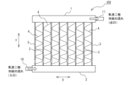
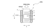
- FIG. 1 is a front view schematically showing a heat exchanger 100 according to the first embodiment.
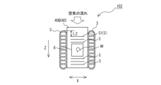
- FIG. 2 is a perspective view schematically showing main parts of the heat exchanger 100 according to the first embodiment.
- FIG. 3 is a front view schematically showing the main parts of the heat exchanger 100 according to the first embodiment.
- the heat exchanger 100 includes a pair of headers 1 and 2 that are spaced apart from each other, and a pair of headers 1 and 2 that are spaced from each other and arranged in parallel in the left-right direction. It has a plurality of flat heat exchanger tubes 3 and a plurality of corrugated fins 4 respectively provided between adjacent flat heat exchanger tubes 3.
- the pair of headers 1 and 2 consists of an upper header 1 and a lower header 2.
- the upper header 1 and the lower header 2 are pipes connected to other devices constituting the refrigeration cycle device, respectively, through which refrigerant serving as a heat exchange medium flows in and out, and the refrigerants are branched or merged.
- a gaseous refrigerant passes through the upper header 1.
- a liquid refrigerant passes through the lower header 2.
- a plurality of flat heat exchanger tubes 3 are arranged in parallel between the upper header 1 and the lower header 2.
- the flat heat exchanger tube 3 is made of, for example, an aluminum alloy, and has a flat cross section as shown in FIG.
- the outer surface (flat surface 31) on the long side of the flat shape is flat, and the outer surface on the shorter side of the flat shape is curved.
- the flat heat exchanger tube 3 has a plurality of refrigerant channels 30 that flow in the vertical direction inside.
- the plurality of flat heat exchanger tubes 3 are arranged vertically so that the flat surfaces 31 are substantially parallel to each other, and are arranged so that the flat surfaces 31 are substantially perpendicular to each header 1 and 2. . That is, the flat heat exchanger tubes 3 are arranged so that the flat surfaces 31 are along the air flow direction Z.
- the upper end of the flat heat exchanger tube 3 is inserted into an insertion hole (not shown) formed in the upper header 1 and joined by brazing.
- the lower end of the flat heat exchanger tube 3 is inserted into an insertion hole (not shown) formed in the lower header 2 and joined by brazing.
- the refrigerant flow path 30 extends in the vertical direction and communicates with the upper header 1 and the lower header 2.
- a brazing material containing aluminum is used as the brazing material for brazing.
- the corrugated fins 4 are made of, for example, an aluminum alloy, and are provided to widen the heat transfer area between the refrigerant flowing in the refrigerant flow path 30 of the flat heat exchanger tube 3 and the outside air.
- the space between the corrugated fins 4 and the flat heat exchanger tubes 3 is a ventilation path through which air flows.
- the corrugated fin 4 is formed by corrugating a flat fin material, bending it by repeating mountain folds and valley folds, and forming a corrugated bellows. It is something that Note that the surface of the fin material is clad with a brazing material layer whose main material is, for example, an aluminum-silicon-based brazing material containing aluminum.
- the thickness of the corrugated fins 4 is, for example, about 50 ⁇ m to 200 ⁇ m.
- the corrugated fin 4 has a flat fin portion 40 and a top portion 41 formed at both ends of the fin portion 40.
- the top portion 41 is a bent portion formed into a wavy shape with concavities and convexities.
- the corrugated fins 4 are provided between two adjacent flat heat exchanger tubes 3 among the plurality of flat heat exchanger tubes 3 so that the wave shape continues in the tube axis direction Y of the flat heat exchanger tubes 3. That is, as shown in FIG. 1, the corrugated fins 4 are arranged so that the fin portions 40 are alternately inclined in opposite directions when viewed from the air flow direction Z.
- the bent top portions 41 of the corrugated fins 4 are in surface contact with the flat surfaces 31 of the two flat heat exchanger tubes 3 and are joined by brazing.
- the fin portion 40 of the corrugated fin 4 is provided with a plurality of louvers 5.
- the louver 5 is provided to increase the heat transfer coefficient between the refrigerant flowing in the refrigerant flow path 30 of the flat heat exchanger tube 3 and the outside air.
- the louver 5 has a slit 5a through which air passes, and a plate portion 5b that is inclined in the vertical direction and guides the air to the slit 5a.
- the slit 5a has a rectangular shape that is long in the parallel direction X of the flat heat exchanger tubes 3. Generally, the portion punched out when forming the slit 5a is cut and raised to form the plate portion 5b.
- the plate portion 5b has a rectangular shape matching the shape of the slit 5a.
- the louvers 5 are provided in each of a plurality of slits 5a provided along the tube axis direction Y of the flat heat exchanger tube 3.
- the louvers 5 are arranged in parallel along the depth direction of the fin portion 40, which is the air circulation direction Z. That is, the louvers 5 are provided in parallel along the airflow.
- the shape and size of the slit 5a and the plate portion 5b are not limited to the illustrated configuration.
- the louvers 5 may be provided on some of the fin portions 40 or all of the fin portions 40 among the plurality of fin portions 40.
- the fin portion 40 is formed with a drainage hole 6 for discharging condensed water W flowing on the upper surface of the fin portion 40.
- the drain hole 6 may be provided in some of the fin parts 40 or all the fin parts 40 among the plurality of fin parts 40. Further, the shape, number, arrangement, etc. of the drainage holes 6 are merely examples, and are not limited to the illustrated configuration.
- the heat exchanger 100 when the heat exchanger 100 is used as a condenser, a high temperature and high pressure refrigerant flows through the refrigerant flow path 30 of the flat heat exchanger tube 3.
- a low temperature and low pressure refrigerant flows through the refrigerant flow path 30 of the flat heat exchanger tube 3.
- the refrigerant is supplied to the lower side via an inlet pipe 10 that supplies refrigerant from an external device (not shown) to the heat exchanger 100, as shown by the arrow in FIG. Flows into header 2 of .
- the refrigerant flowing into the lower header 2 is distributed to each flat heat exchanger tube 3 and passes through the refrigerant flow path 30 of each flat heat exchanger tube 3.
- the flat heat exchanger tube 3 performs heat exchange between the refrigerant passing through the refrigerant flow path 30 and the outside air passing outside the tube. At this time, the refrigerant absorbs heat from the outside air while passing through the refrigerant flow path 30.
- the refrigerant that has passed through the refrigerant flow path 30 of each flat heat exchanger tube 3 and has been heat exchanged flows into the upper header 1 and merges therewith.
- the refrigerant that has merged inside the upper header 1 passes through the outlet pipe 11 connected to the upper header 1 and is returned to an external device (not shown).
- the heat exchanger 100 When the heat exchanger 100 is used as an evaporator, when the surface temperature of the fin portion 40 decreases, moisture in the air near the surface of the fin portion 40 precipitates and becomes condensed water W, and the surface temperature further drops below the freezing point. Then, the condensed water W freezes and frost formation occurs.
- the amount of heat exchanged is large on the upstream side of the air path where the temperature difference between the air and the fin portions 40 is large, so the amount of condensed water W generated on the surface of the fin portions 40 also increases. The number increases on the upstream side of the wind path.
- the amount of condensed water W increases in the fin portion 40 in the portion where the louvers 5 with high heat transfer coefficient are formed, and when frost formation occurs, the fin portion 40 There is a problem that the gaps between them are easily clogged with frost, and the frost resistance is low.
- Frost resistance means that the heating capacity is large for operating hours under low temperature conditions. That is, in the heat exchanger 100, by setting it as a structure with a large frost resistance, performance deterioration due to frost blockage can be suppressed with respect to operating time.
- the air passages are less likely to be blocked by frost formation, so that the frost resistance is high.
- louvers 5A and 5B are provided.
- the louvers 5A and 5B having different configurations have different width dimensions in the parallel direction X of the flat heat exchanger tubes 3.
- Louvers 5A and 5B having different configurations are periodically formed along the tube axis direction Y of the flat heat exchanger tube 3.
- the heat exchanger 100 shown in FIG. The fin portions 40B in which a plurality of louvers 5B having a short width are formed are arranged alternately along the tube axis direction Y of the flat heat exchanger tube 3. Thereby, as shown in FIG. 3, when the heat exchanger 100 is viewed from the upstream side in the air flow direction Z, low frost formation spaces S are formed on both sides of the louver 5B having a short width.
- the fin portions 40A and 40B appear linear when the heat exchanger 100 is viewed from the upstream side in the air flow direction Z.
- the inclined surfaces of the louvers 5A and 5B can be seen as parts that protrude upward and downward from the linear parts of the fin parts 40A and 40B.
- the amount of frost formation increases as the area of the louvers 5A and 5B that protrude vertically from the surfaces of the fin portions 40A and 40B increases.
- the sum of the protruding areas of the louvers 5A and 5B for each of the fin parts 40A and 40B is calculated, and the larger the sum of the protruding areas of the louvers 5A, the larger the amount of frost formed. This becomes the fin portion 40A.
- a fin portion 40B having a smaller total protruding area of the louvers 5B has the louvers 5B formed thereon with a structure that reduces the amount of frost formation.
- the fin portion 40A having a plurality of louvers 5A with a large amount of frost formation and the fin portion 40B having a plurality of louvers 5B with a small amount of frost formation compared to those fin portions 40A have a flat structure. It is repeated periodically in the tube axis direction Y of the heat exchanger tube 3. Therefore, as shown in FIG. 3, when the heat exchanger 100 is viewed from the upstream side in the air flow direction Z, the existence of the low frost formation space S in which frost formation is difficult to occur allows the air path to remain stable for a long period of time. Since the blockage of air can be suppressed and air can be transported from the upstream side to the downstream side, frost resistance can be improved.
- the heat exchanger 100 may include a fin portion 40 that does not have the louvers 5 among the plurality of fin portions 40.
- frost is less likely to form, so that blockage of the air passage can be suppressed over a long period of time, and air can be transported from the upstream side to the downstream side.
- FIG. 4 is a front view schematically showing a main part of the heat exchanger 100 according to the first embodiment, which is different from FIG. 3.
- the heat exchanger 100 according to the first embodiment has two fin sections 40 that are continuous along the tube axis direction Y as one set among the plurality of fin sections 40.
- louvers 5A or 5B having different widths in the parallel direction X of the flat heat exchanger tubes 3 may be provided.
- the heat exchanger 100 according to the first embodiment includes one set of three or more fin parts 40 that are continuous along the tube axis direction Y among the plurality of fin parts 40. or other combinations may be used.
- louvers 5 having three or more different configurations may be provided for each selected fin portion 40. Also in these cases, the louvers 5 of different configurations are periodically formed along the tube axis direction Y of the flat heat exchanger tube 3.
- FIG. 5 is an explanatory diagram schematically showing an example of manufacturing the corrugated fins 4 of the heat exchanger 100 according to the first embodiment by roll forming.
- the corrugated fin 4 is manufactured by passing the fin material 7 between corrugated cutters 80 arranged above and below.
- the corrugate cutter 80 may have different specifications for the blade 80a and the blade 80b, for example.
- the corrugate fins 4 are formed into louvers 5A and 5B having different widths in the parallel direction X of the flat heat exchanger tubes 3, as shown in FIGS. 3 and 4. can be formed.
- louvers 5A and 5B having different configurations may be provided irregularly along the tube axis direction Y of the flat heat exchanger tube 3, but as shown in FIG. 4, the corrugated fins 4 are generally formed by roll forming. Considering that they are manufactured, it is desirable to form them periodically along the tube axis direction Y of the flat heat exchanger tube 3.
- FIG. 6 is a refrigerant circuit diagram of a refrigeration cycle device 200 including the heat exchanger 100 according to the first embodiment.
- an air conditioner will be described as an example of the refrigeration cycle device 200.
- an outdoor unit 201 and an indoor unit 202 are connected through a gas refrigerant pipe 300 and a liquid refrigerant pipe 301, thereby forming a refrigerant circuit.
- the outdoor unit 201 includes a compressor 203, a flow path switching device 204, an outdoor heat exchanger 205, and an outdoor fan 206.
- the indoor unit 202 includes an expansion mechanism 207, an indoor heat exchanger 208, and an indoor fan 209.
- the refrigerant circuit is configured by sequentially connecting a compressor 203, a flow path switching device 204, an outdoor heat exchanger 205, an expansion mechanism 207, and an indoor heat exchanger 208 through a gas refrigerant pipe 300 and a liquid refrigerant pipe 301. has been done.
- the heat exchanger 100 described in the first embodiment is mainly used as the outdoor heat exchanger 205.
- the heat exchanger 100 described in the first embodiment may be used as the indoor heat exchanger 208, or may be used as both the outdoor heat exchanger 205 and the indoor heat exchanger 208.
- one outdoor unit 201 and one indoor unit 202 are connected by a gas refrigerant pipe 300 and a liquid refrigerant pipe 301.
- the number of outdoor units 201 and indoor units 202 is not limited to one.
- the compressor 203 compresses the sucked refrigerant and discharges it in a high temperature and high pressure state.
- the compressor 203 is, for example, a positive displacement compressor that is configured to have a variable operating capacity and is driven by a motor that is controlled by an inverter.
- the flow path switching device 204 is, for example, a four-way valve, and has a function of switching the refrigerant flow path.
- the flow path switching device 204 connects the refrigerant discharge side of the compressor 203 and the gas side of the outdoor heat exchanger 205, and also connects the refrigerant suction side of the compressor 203 and the indoor heat exchanger 208. Switch the refrigerant flow path to connect it to the gas side.
- the flow path switching device 204 connects the refrigerant discharge side of the compressor 203 and the gas side of the indoor heat exchanger 208, and also connects the refrigerant suction side of the compressor 203 and the outdoor heat exchanger 208.
- the refrigerant flow path is switched so that it connects to the gas side of 205.
- the flow path switching device 204 may be configured by combining two-way valves or three-way valves.
- the outdoor heat exchanger 205 functions as an evaporator during heating operation, and exchanges heat between the refrigerant flowing inside the expansion mechanism 207 and the outdoor air. Furthermore, the outdoor heat exchanger 205 functions as a condenser during cooling operation, and performs heat exchange between the refrigerant discharged from the compressor 203 and flowing inside and outdoor air. The outdoor heat exchanger 205 sucks in outdoor air using the outdoor fan 206, and discharges the air that has undergone heat exchange with the refrigerant to the outside.
- the expansion mechanism 207 depressurizes and expands the refrigerant flowing out from the condenser, and is composed of, for example, an electronic expansion valve that can adjust the opening degree of the throttle.
- the expansion mechanism 207 controls the pressure of the refrigerant flowing into the outdoor heat exchanger 205 or the indoor heat exchanger 208 by adjusting the opening degree.
- the indoor heat exchanger 208 functions as a condenser during heating operation, and exchanges heat between the refrigerant discharged from the compressor 203 and flowing inside and the indoor air.
- the indoor heat exchanger 208 functions as an evaporator during cooling operation, and performs heat exchange between the refrigerant flowing inside the expansion mechanism 207 and the indoor air.
- the indoor heat exchanger 208 sucks indoor air using the indoor fan 209, and supplies the air into the room after exchanging heat with the refrigerant.
- the flow path switching device 204 is switched to the dotted line side in FIG. 6 .
- the high-temperature, high-pressure gas refrigerant compressed and discharged by the compressor 203 passes through the flow path switching device 204 and flows into the indoor heat exchanger 208 .
- the gas refrigerant that has flowed into the indoor heat exchanger 208 exchanges heat with the air in the air-conditioned space sent from the indoor fan 209, and is condensed and liquefied.
- the liquefied refrigerant is depressurized by the expansion mechanism 207 to become a low-temperature, low-pressure gas-liquid two-phase refrigerant, and then flows into the outdoor heat exchanger 205 .
- the liquid refrigerant that has flowed into the outdoor heat exchanger 205 exchanges heat with the outdoor air sent from the outdoor fan 206, evaporates, and becomes gas.
- the gasified refrigerant passes through the flow path switching device 204 and is sucked into the compressor 203 again.
- the flow path switching device 204 is switched to the solid line side in FIG. 6 .
- the high-temperature, high-pressure gas refrigerant compressed and discharged by the compressor 203 passes through the flow path switching device 204 and flows into the outdoor heat exchanger 205 .
- the gas refrigerant that has flowed into the outdoor heat exchanger 205 exchanges heat with the outdoor air sent from the outdoor fan 206, and is condensed and liquefied.
- the liquefied refrigerant is depressurized by the expansion mechanism 207 to become a low-temperature, low-pressure gas-liquid two-phase refrigerant, and then flows into the indoor heat exchanger 208 .
- the liquid refrigerant that has flowed into the indoor heat exchanger 208 exchanges heat with the air in the air-conditioned space sent from the indoor fan 209, evaporates, and becomes gas.
- the gasified refrigerant passes through the flow path switching device 204 and is sucked into the compressor 203 again.
- FIGS. 7 and 8 are plan views schematically showing the main parts of the heat exchanger 101 according to the second embodiment. Note that the same components as those of the heat exchanger 100 described in the first embodiment are given the same reference numerals, and the description thereof will be omitted as appropriate.
- the heat exchanger 101 has a louver 5 provided on one fin section 40 for each selected fin section 40 among the plurality of fin sections 40.
- the number of lines is different.
- the different numbers of louvers 5 are periodically formed along the tube axis direction Y of the flat heat exchanger tube 3.
- the heat exchanger 101 has a fin section 40A with a large number of louvers 5 shown in FIG. 7, and a fin section 40B with a small number of louvers 5 shown in FIG. , are arranged alternately along the tube axis direction Y of the flat heat exchanger tubes 3.
- the heat transfer coefficient due to the louvers 5 is small, so the amount of frost formation is reduced, thereby making it possible to form a space with low frost formation.
- the fin portion 40B by having the fin portion 40B with a small number of louvers 5, blockage of the air passage can be suppressed over a long period of time, and air can be transported from the upstream side to the downstream side. Therefore, frost resistance can be improved.
- the number of louvers 5 is not limited to the number shown, and may be changed as appropriate depending on the performance of the heat exchanger 101.
- the heat exchanger 101 according to the second embodiment may include a fin portion 40 that does not have the louver 5 among the plurality of fin portions 40.
- frost is less likely to form, so that blockage of the air passage can be suppressed over a long period of time, and air can be transported from the upstream side to the downstream side.
- the heat exchanger 101 has two fin portions 40 that are continuous along the tube axis direction Y among the plurality of fin portions 40 as one set.
- a louver 5 having a different configuration may be provided.
- among the plurality of fin parts 40 three or more fin parts 40 that are continuous along the tube axis direction Y of the flat heat exchanger tube 3 may be set as one set, or other combinations may be used. But that's fine.
- three or more types of different numbers of louvers 5 may be provided for each selected fin portion 40. Also in these cases, different numbers of louvers 5 are formed periodically along the tube axis direction Y of the flat heat exchanger tube 3.
- heat exchanger 101 according to the second embodiment may be combined with the features of the heat exchanger 100 described in the first embodiment.
- Embodiment 3 Next, the heat exchanger 102 according to the third embodiment will be described with reference to FIGS. 9 and 10.
- 9 and 10 are plan views schematically showing main parts of the heat exchanger 102 according to the third embodiment. Note that the same components as those of heat exchangers 100 and 101 described in Embodiments 1 and 2 above are given the same reference numerals, and the description thereof will be omitted as appropriate.
- the heat exchanger 102 is configured such that each selected fin section 40 is provided at the most upstream side of the air path for each selected fin section 40 among the plurality of fin sections 40.
- the louvers 50 and 51 are arranged in different positions. Louvers 50 and 51 having different configurations are periodically formed along the tube axis direction Y of the flat heat exchanger tube 3.
- the louver 50 provided at the most upstream side of the air path of the fin portion 40A shown in FIG. has been done.
- the louver 51 provided on the furthest upstream side of the air path of the fin portion 40B shown in FIG. 10 is formed at a position a distance L2 from the upstream end of the flat heat exchanger tube 3 toward the downstream.
- the relationship between distance L1 and distance L2 is L1>L2.
- the fin portions 40A having the louvers 50 and the fin portions 40B having the louvers 51 are alternately arranged along the tube axis direction Y of the flat heat exchanger tube 3.
- the louver 50 provided on the most upstream side of the air path is formed at a position away from the upstream end of the flat heat exchanger tube 3 toward the downstream.
- louvers 5 is not limited to the number shown, and may be changed as appropriate depending on the performance of the heat exchanger 102.
- the heat exchanger 102 may include a fin portion 40 that does not have the louver 5 among the plurality of fin portions 40.
- frost is less likely to form, so that blockage of the air passage can be suppressed over a long period of time, and air can be transported from the upstream side to the downstream side.
- the heat exchanger 102 includes one set of two fin parts 40 that are continuous along the tube axis direction Y of the flat heat exchanger tube 3 among the plurality of fin parts 40. Then, louvers 5 having different configurations may be provided for each group. Further, although not shown in the drawings, among the plurality of fin parts 40, three or more fin parts 40 that are continuous along the tube axis direction Y of the flat heat exchanger tube 3 may be set as one set, or other combinations may be used. But that's fine. Further, louvers 5 having three or more different configurations may be provided for each selected fin portion 40. Also in these cases, the louvers 5 of different configurations are periodically formed along the tube axis direction Y of the flat heat exchanger tube 3.
- heat exchanger 100 according to the third embodiment may be combined with the features of the heat exchangers 100 and 101 described in the first and second embodiments above.
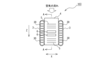
- FIG. 11 is a plan view schematically showing the main parts of the heat exchanger 103 according to the fourth embodiment.
- FIG. 12 is a sectional view taken along the line AA shown in FIG. 11.
- FIG. 13 is a cross-sectional view taken along the line AA shown in FIG. 11, showing a configuration different from that in FIG. 12. Note that the same components as those of the heat exchangers 100 to 102 described in the first to third embodiments are given the same reference numerals, and the description thereof will be omitted as appropriate.
- the heat exchanger 103 has an inclination angle ⁇ of the plate portion 5b of the louver 5 for each selected fin portion 40 among the plurality of fin portions 40. are configured so that they are different. Louvers 5 having different configurations are periodically formed along the tube axis direction Y of the flat heat exchanger tube 3.
- the heat exchanger 103 includes a fin portion 40A in which a louver 52 with a small inclination angle ⁇ 1 of the plate portion 5b is formed, and a fin portion 40A as shown in FIG.
- the fin portions 40B in which the louvers 53 having the large inclination angle ⁇ 2 of the plate portion 5b are formed are arranged alternately along the tube axis direction Y of the flat heat exchanger tube 3.
- Arrow B shown in FIGS. 12 and 13 indicates the flow of air passing through the slit 5a.
- the plate portion 5b formed on the upstream side of the air path from the drainage hole 6 and the plate portion 5b formed on the downstream side of the air path from the drainage hole 6 are inclined in opposite directions. However, they may be in the same direction.
- the heat transfer coefficient at the louver 52 is suppressed compared to the fin portion 40A having the louver 53 with a large inclination angle ⁇ 2 of the plate portion 5b. Therefore, by reducing frost formation, a low frost formation space can be formed. Therefore, in the heat exchanger 100 according to the fourth embodiment, by having the fin portion 40A in which the louver 52 with the small inclination angle ⁇ 1 of the plate portion 5b is formed, blockage of the air passage can be suppressed over a long period of time. Since air can be transported from the windward side to the downstream side, frost resistance can be improved.
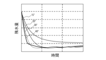
- FIG. 14 shows the relationship between the time for draining condensed water W and the amount of residual water remaining on the surface of the fin portion 40 with respect to the inclination angle ⁇ of the plate portion 5b in the heat exchanger 103 according to the fourth embodiment.
- This is a graph.
- the horizontal axis in FIG. 14 indicates time.
- the vertical axis in FIG. 14 indicates the amount of remaining water.
- the inclination angle ⁇ of the plate portion 5b is 15°, 20°, 30°, and 40°, respectively.
- the graph of FIG. 14 shows that the smaller the amount of residual water in a short time, the better the drainage performance.
- the louvers 5 should be set so that the inclination angle ⁇ of the plate portion 5b falls within the range of 20° ⁇ 40°. It is preferable to form For example, in the case shown in FIGS. 12 and 13, it is preferable that the inclination angles ⁇ 1 and ⁇ 2 of the plate portion 5b satisfy 20° ⁇ 1 ⁇ 2 ⁇ 40.
- the heat exchanger 103 may include a fin portion 40 that does not have the louver 5 among the plurality of fin portions 40.
- frost is less likely to form, so that blockage of the air passage can be suppressed over a long period of time, and air can be transported from the upstream side to the downstream side.
- the heat exchanger 103 includes one set of two fin parts 40 that are continuous along the tube axis direction Y of the flat heat exchanger tube 3 among the plurality of fin parts 40. Then, louvers 5 having different configurations may be provided for each group. Further, although not shown in the drawings, among the plurality of fin parts 40, three or more fin parts 40 that are continuous along the tube axis direction Y of the flat heat exchanger tube 3 may be set as one set, or other combinations may be used. But that's fine. Further, louvers 5 having three or more different configurations may be provided for each selected fin portion 40. Also in these cases, the louvers 5 of different configurations are periodically formed along the tube axis direction Y of the flat heat exchanger tube 3.
- heat exchanger 103 according to the fourth embodiment may be combined with the features of the heat exchangers 100 to 102 described in the first to third embodiments above.
- FIGS. 15 and 16 are plan views schematically showing the main parts of the heat exchanger 104 according to the fifth embodiment. Note that the same components as those of the heat exchangers 100 to 103 described in Embodiments 1 to 4 are given the same reference numerals, and the description thereof will be omitted as appropriate.
- the heat exchanger 104 has a different configuration so as to change the frost amount for each selected fin section 40 among the plurality of fin sections 40.
- a drainage hole 6 is provided.
- the drainage holes 6 having different configurations are configurations in which the total opening area of the drainage holes 6 formed in one fin portion 40 is different. Drain holes 6 having different configurations are periodically formed along the tube axis direction Y of the flat heat exchanger tube 3.
- the heat exchanger 104 includes a fin portion 40A having a small total opening area of the plurality of drainage holes 6 shown in FIG. 15, and a plurality of drainage holes 6 shown in FIG.
- the fin portions 40B having a large total opening area are arranged alternately along the tube axis direction Y of the flat heat exchanger tube 3.
- two drainage holes 6 of the same shape and size are formed side by side along the air flow direction Z, as an example. ing.
- the fin portion 40B where the total opening area of the drainage holes 6 is large the drainage speed of the condensed water W is fast, so the amount of residual water is small, and the condensed water W on the surface is difficult to freeze even under low temperature conditions.
- the heat exchanger 104 since the heat transfer coefficient of the fin portion 40B is reduced by the drainage holes 6, a low frost formation space is formed around the drainage holes 6 in which frost is difficult to grow, and the frost resistance is improved. I can do it.
- the fin portions 40B between adjacent drainage holes 6 serve as a water guiding area for condensed water W, and the condensed water W falls into the drainage holes 6 along the water guiding area, so that drainage performance is improved.
- drain holes 6 are not limited to the illustrated configuration.
- drain holes 6 having different shapes may be formed in the same fin portion 40.
- the configurations described in the first to fourth embodiments above are applied to the louver 5 of the heat exchanger 104 according to the fifth embodiment.
- the heat exchanger 104 includes one set of two fin parts 40 that are continuous along the tube axis direction Y of the flat heat exchanger tube 3 among the plurality of fin parts 40.
- the drain holes 6 may have different configurations for each group.
- among the plurality of fin parts 40 three or more fin parts 40 that are continuous along the tube axis direction Y of the flat heat exchanger tube 3 may be set as one set, or other combinations may be used. But that's fine.
- the drainage holes 6 having three or more different configurations may be formed for each selected fin portion 40. Even in these cases, drain holes 6 having different configurations are periodically formed along the tube axis direction Y of the flat heat exchanger tube 3.
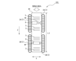
- FIGS. 17 and 18 are plan views schematically showing main parts of a modification of the heat exchanger 104 according to the fifth embodiment.
- drain holes 6 having different opening areas are provided for each selected fin part 40 among the plurality of fin parts 40.
- each fin portion 40 has one drainage hole 6. Drain holes 6 having different configurations are periodically formed along the tube axis direction Y of the flat heat exchanger tube 3.
- a fin portion 40A with a small opening area of the drain hole 60 shown in FIG. 17 and a fin portion 40B with a large opening area of the drain hole 61 shown in FIG. They are arranged alternately along the direction Y. Also in the heat exchanger 104A shown in FIGS. 17 and 18, in the fin portion 40B where the opening area of the drain hole 61 is large, the draining speed of the condensed water W is fast, so the amount of residual water is small and the surface remains clean even under low temperature conditions. Condensed water W is difficult to freeze.
- the heat exchanger 104A since the heat transfer coefficient of the fin portion 40B is reduced by the drainage holes 61, a low frost formation space is formed around the drainage holes 61 in which frost is difficult to grow, and the frost resistance is improved. I can do it.
- the shape, arrangement, etc. of the drainage holes 60 and 61 are merely examples, and are not limited to the illustrated configuration.
- FIG. 19 is a plan view schematically showing the main parts of the heat exchanger 105 according to the sixth embodiment. Note that the same components as those of the heat exchangers 100 to 104 described in Embodiments 1 to 5 are given the same reference numerals, and the description thereof will be omitted as appropriate.
- the heat exchanger 105 has a configuration in which two rows of flat heat exchanger tubes 3 are arranged along the air flow direction Z.
- the flat heat exchanger tube 3 includes a flat heat exchanger tube 3A disposed on the upstream side of the air path, and a flat heat exchanger tube 3B placed on the downstream side of the air path.
- the flat heat exchanger tubes 3 are not limited to the illustrated two rows, but may be arranged in three or more rows along the air circulation direction Z.
- the louver 5 or drain hole 6 having the configuration described in the first to fifth embodiments above is applied to the fin portion 40.
- the heat exchanger 105 can be configured by applying the configuration described in the first to fifth embodiments to the fin portion 40 surrounded by the flat heat transfer tubes 3A on the upstream side of the air path.
- the side fin portions 40 can suppress blockage of the air passage for a long period of time, and can transport air from the upstream side to the downstream side, so that frost resistance can be improved.
- FIG. 20 is a graph showing the relationship between the dimensions of the fin portion 40 in the air circulation direction Z and the rate of improvement in heating capacity at low temperatures.
- the horizontal axis in FIG. 20 indicates the dimension of the fin portion 40 in the air circulation direction Z.
- the vertical axis in FIG. 20 indicates the rate of improvement in heating capacity at low temperatures.
- the effect is particularly effective when the length L3 of the fin portion 40 in the air flow direction Z is set to 22 mm or more, as shown in FIG. .
- the heat exchanger 100 and the refrigeration cycle device 200 have been described above based on the embodiments, they are not limited to the configurations of the embodiments described above.
- the heat exchangers (100 to 105) and the refrigeration cycle device 200 are not limited to the illustrated configuration, and may include other components.
- the heat exchangers (100 to 105) and the refrigeration cycle device 200 are subject to a range of design changes and application variations that are commonly made by those skilled in the art without departing from the technical concept thereof.
Abstract
L'échangeur de chaleur de l'invention comporte une section transversale aplatie, plusieurs voies d'écoulement de fluide frigorigène, plusieurs tubes aplatis de transfert de chaleur disposés parallèlement à intervalles et plusieurs ailettes ondulées disposées respectivement entre les tubes aplatis de transfert de chaleur adjacents. Les ailettes ondulées sont formées par pliage sous forme de vague, de sorte que des parties d'ailettes sous forme de plaques plates sont disposées parallèlement le long de la direction de l'axe du tube des tubes de transfert de chaleur aplatis. Une persienne est installée sur la partie d'ailette. Une persienne ayant une configuration différente de manière à modifier la quantité de formation de givre est prévue pour chaque ailette sélectionnée parmi la pluralité d'ailettes.
Priority Applications (1)
| Application Number | Priority Date | Filing Date | Title |
|---|---|---|---|
| PCT/JP2022/010358 WO2023170834A1 (fr) | 2022-03-09 | 2022-03-09 | Échangeur de chaleur et dispositif à cycle de réfrigération équipé de l'échangeur de chaleur |
Applications Claiming Priority (1)
| Application Number | Priority Date | Filing Date | Title |
|---|---|---|---|
| PCT/JP2022/010358 WO2023170834A1 (fr) | 2022-03-09 | 2022-03-09 | Échangeur de chaleur et dispositif à cycle de réfrigération équipé de l'échangeur de chaleur |
Publications (1)
| Publication Number | Publication Date |
|---|---|
| WO2023170834A1 true WO2023170834A1 (fr) | 2023-09-14 |
Family
ID=87936406
Family Applications (1)
| Application Number | Title | Priority Date | Filing Date |
|---|---|---|---|
| PCT/JP2022/010358 WO2023170834A1 (fr) | 2022-03-09 | 2022-03-09 | Échangeur de chaleur et dispositif à cycle de réfrigération équipé de l'échangeur de chaleur |
Country Status (1)
| Country | Link |
|---|---|
| WO (1) | WO2023170834A1 (fr) |
Citations (6)
| Publication number | Priority date | Publication date | Assignee | Title |
|---|---|---|---|---|
| JPS57114276U (fr) * | 1980-12-26 | 1982-07-15 | ||
| JPS60154772U (ja) * | 1984-03-26 | 1985-10-15 | カルソニックカンセイ株式会社 | コルゲ−トフイン |
| JPH08178366A (ja) * | 1994-12-21 | 1996-07-12 | Sharp Corp | 熱交換器 |
| JP2004271116A (ja) * | 2003-03-11 | 2004-09-30 | Japan Climate Systems Corp | 熱交換器のフィン構造 |
| US20150377558A1 (en) * | 2013-02-01 | 2015-12-31 | Halla Visteon Climate Control Corp. | Heat exchange system |
| US20210348858A1 (en) * | 2018-12-19 | 2021-11-11 | Carrier Corporation | Aluminum heat exchanger with fin arrangement for sacrificial corrosion protection |
-
2022
- 2022-03-09 WO PCT/JP2022/010358 patent/WO2023170834A1/fr unknown
Patent Citations (6)
| Publication number | Priority date | Publication date | Assignee | Title |
|---|---|---|---|---|
| JPS57114276U (fr) * | 1980-12-26 | 1982-07-15 | ||
| JPS60154772U (ja) * | 1984-03-26 | 1985-10-15 | カルソニックカンセイ株式会社 | コルゲ−トフイン |
| JPH08178366A (ja) * | 1994-12-21 | 1996-07-12 | Sharp Corp | 熱交換器 |
| JP2004271116A (ja) * | 2003-03-11 | 2004-09-30 | Japan Climate Systems Corp | 熱交換器のフィン構造 |
| US20150377558A1 (en) * | 2013-02-01 | 2015-12-31 | Halla Visteon Climate Control Corp. | Heat exchange system |
| US20210348858A1 (en) * | 2018-12-19 | 2021-11-11 | Carrier Corporation | Aluminum heat exchanger with fin arrangement for sacrificial corrosion protection |
Similar Documents
| Publication | Publication Date | Title |
|---|---|---|
| EP2857785B1 (fr) | Echangeur de chaleur et climatiseur | |
| KR101451057B1 (ko) | 열교환기 및 공기 조화기 | |
| US11009300B2 (en) | Heat exchanger and air-conditioning apparatus | |
| EP4060276B1 (fr) | Échangeur de chaleur et dispositif à cycle frigorifique | |
| JP3068761B2 (ja) | 熱交換器 | |
| WO2021234964A1 (fr) | Échangeur de chaleur et conditionneur d'air | |
| WO2018207321A1 (fr) | Échangeur de chaleur et dispositif à cycle frigorifique | |
| JP2004271113A (ja) | 熱交換器 | |
| US11573056B2 (en) | Heat exchanger, heat exchanger unit, and refrigeration cycle apparatus | |
| WO2023170834A1 (fr) | Échangeur de chaleur et dispositif à cycle de réfrigération équipé de l'échangeur de chaleur | |
| JP2021191996A (ja) | 伝熱管、及び、熱交換器 | |
| JP7313334B2 (ja) | 熱交換器及び冷凍サイクル装置 | |
| JP7353518B1 (ja) | 熱交換器及び空気調和装置 | |
| WO2023199400A1 (fr) | Échangeur de chaleur et dispositif à cycle de réfrigération | |
| JP6548824B2 (ja) | 熱交換器および冷凍サイクル装置 | |
| WO2022219919A1 (fr) | Échangeur de chaleur et dispositif à cycle de réfrigération | |
| JP7150157B2 (ja) | 熱交換器および冷凍サイクル装置 | |
| WO2018040034A1 (fr) | Échangeur de chaleur à micro-canal et réfrigérateur refroidi par air | |
| US20240159474A1 (en) | Heat exchanger and refrigeration cycle apparatus | |
| JP7399286B2 (ja) | 熱交換器および冷凍サイクル装置 | |
| WO2021205905A1 (fr) | Échangeur de chaleur, climatiseur et procédé de fabrication d'un échangeur de chaleur | |
| WO2021234957A1 (fr) | Échangeur de chaleur et climatiseur comprenant ledit échangeur de chaleur | |
| US20240118040A1 (en) | Heat exchanger | |
| US20240159481A1 (en) | Heat exchanger and refrigeration cycle apparatus | |
| WO2021245734A1 (fr) | Échangeur de chaleur et appareil à cycle de réfrigération |
Legal Events
| Date | Code | Title | Description |
|---|---|---|---|
| 121 | Ep: the epo has been informed by wipo that ep was designated in this application |
Ref document number: 22930816 Country of ref document: EP Kind code of ref document: A1 |