WO2023199825A1 - 非水電解質二次電池 - Google Patents
非水電解質二次電池 Download PDFInfo
- Publication number
- WO2023199825A1 WO2023199825A1 PCT/JP2023/014109 JP2023014109W WO2023199825A1 WO 2023199825 A1 WO2023199825 A1 WO 2023199825A1 JP 2023014109 W JP2023014109 W JP 2023014109W WO 2023199825 A1 WO2023199825 A1 WO 2023199825A1
- Authority
- WO
- WIPO (PCT)
- Prior art keywords
- electrode
- current collector
- secondary battery
- negative electrode
- aqueous electrolyte
- Prior art date
- Legal status (The legal status is an assumption and is not a legal conclusion. Google has not performed a legal analysis and makes no representation as to the accuracy of the status listed.)
- Ceased
Links
Images


Classifications
-
- H—ELECTRICITY
- H01—ELECTRIC ELEMENTS
- H01M—PROCESSES OR MEANS, e.g. BATTERIES, FOR THE DIRECT CONVERSION OF CHEMICAL ENERGY INTO ELECTRICAL ENERGY
- H01M10/00—Secondary cells; Manufacture thereof
- H01M10/05—Accumulators with non-aqueous electrolyte
- H01M10/058—Construction or manufacture
- H01M10/0587—Construction or manufacture of accumulators having only wound construction elements, i.e. wound positive electrodes, wound negative electrodes and wound separators
-
- H—ELECTRICITY
- H01—ELECTRIC ELEMENTS
- H01M—PROCESSES OR MEANS, e.g. BATTERIES, FOR THE DIRECT CONVERSION OF CHEMICAL ENERGY INTO ELECTRICAL ENERGY
- H01M10/00—Secondary cells; Manufacture thereof
- H01M10/04—Construction or manufacture in general
- H01M10/0431—Cells with wound or folded electrodes
-
- H—ELECTRICITY
- H01—ELECTRIC ELEMENTS
- H01M—PROCESSES OR MEANS, e.g. BATTERIES, FOR THE DIRECT CONVERSION OF CHEMICAL ENERGY INTO ELECTRICAL ENERGY
- H01M10/00—Secondary cells; Manufacture thereof
- H01M10/05—Accumulators with non-aqueous electrolyte
- H01M10/052—Li-accumulators
- H01M10/0525—Rocking-chair batteries, i.e. batteries with lithium insertion or intercalation in both electrodes; Lithium-ion batteries
-
- H—ELECTRICITY
- H01—ELECTRIC ELEMENTS
- H01M—PROCESSES OR MEANS, e.g. BATTERIES, FOR THE DIRECT CONVERSION OF CHEMICAL ENERGY INTO ELECTRICAL ENERGY
- H01M4/00—Electrodes
- H01M4/02—Electrodes composed of, or comprising, active material
- H01M4/64—Carriers or collectors
- H01M4/66—Selection of materials
- H01M4/661—Metal or alloys, e.g. alloy coatings
-
- H—ELECTRICITY
- H01—ELECTRIC ELEMENTS
- H01M—PROCESSES OR MEANS, e.g. BATTERIES, FOR THE DIRECT CONVERSION OF CHEMICAL ENERGY INTO ELECTRICAL ENERGY
- H01M4/00—Electrodes
- H01M4/02—Electrodes composed of, or comprising, active material
- H01M4/64—Carriers or collectors
- H01M4/66—Selection of materials
- H01M4/665—Composites
- H01M4/667—Composites in the form of layers, e.g. coatings
-
- H—ELECTRICITY
- H01—ELECTRIC ELEMENTS
- H01M—PROCESSES OR MEANS, e.g. BATTERIES, FOR THE DIRECT CONVERSION OF CHEMICAL ENERGY INTO ELECTRICAL ENERGY
- H01M4/00—Electrodes
- H01M4/02—Electrodes composed of, or comprising, active material
- H01M4/64—Carriers or collectors
- H01M4/66—Selection of materials
- H01M4/669—Steels
-
- H—ELECTRICITY
- H01—ELECTRIC ELEMENTS
- H01M—PROCESSES OR MEANS, e.g. BATTERIES, FOR THE DIRECT CONVERSION OF CHEMICAL ENERGY INTO ELECTRICAL ENERGY
- H01M50/00—Constructional details or processes of manufacture of the non-active parts of electrochemical cells other than fuel cells, e.g. hybrid cells
- H01M50/10—Primary casings; Jackets or wrappings
- H01M50/102—Primary casings; Jackets or wrappings characterised by their shape or physical structure
- H01M50/107—Primary casings; Jackets or wrappings characterised by their shape or physical structure having curved cross-section, e.g. round or elliptic
-
- H—ELECTRICITY
- H01—ELECTRIC ELEMENTS
- H01M—PROCESSES OR MEANS, e.g. BATTERIES, FOR THE DIRECT CONVERSION OF CHEMICAL ENERGY INTO ELECTRICAL ENERGY
- H01M50/00—Constructional details or processes of manufacture of the non-active parts of electrochemical cells other than fuel cells, e.g. hybrid cells
- H01M50/30—Arrangements for facilitating escape of gases
- H01M50/383—Flame arresting or ignition-preventing means
-
- Y—GENERAL TAGGING OF NEW TECHNOLOGICAL DEVELOPMENTS; GENERAL TAGGING OF CROSS-SECTIONAL TECHNOLOGIES SPANNING OVER SEVERAL SECTIONS OF THE IPC; TECHNICAL SUBJECTS COVERED BY FORMER USPC CROSS-REFERENCE ART COLLECTIONS [XRACs] AND DIGESTS
- Y02—TECHNOLOGIES OR APPLICATIONS FOR MITIGATION OR ADAPTATION AGAINST CLIMATE CHANGE
- Y02E—REDUCTION OF GREENHOUSE GAS [GHG] EMISSIONS, RELATED TO ENERGY GENERATION, TRANSMISSION OR DISTRIBUTION
- Y02E60/00—Enabling technologies; Technologies with a potential or indirect contribution to GHG emissions mitigation
- Y02E60/10—Energy storage using batteries
-
- Y—GENERAL TAGGING OF NEW TECHNOLOGICAL DEVELOPMENTS; GENERAL TAGGING OF CROSS-SECTIONAL TECHNOLOGIES SPANNING OVER SEVERAL SECTIONS OF THE IPC; TECHNICAL SUBJECTS COVERED BY FORMER USPC CROSS-REFERENCE ART COLLECTIONS [XRACs] AND DIGESTS
- Y02—TECHNOLOGIES OR APPLICATIONS FOR MITIGATION OR ADAPTATION AGAINST CLIMATE CHANGE
- Y02P—CLIMATE CHANGE MITIGATION TECHNOLOGIES IN THE PRODUCTION OR PROCESSING OF GOODS
- Y02P70/00—Climate change mitigation technologies in the production process for final industrial or consumer products
- Y02P70/50—Manufacturing or production processes characterised by the final manufactured product
Definitions
- the present disclosure relates to a non-aqueous electrolyte secondary battery.
- Patent Document 1 discloses a wound electrode body which is formed by forming a mixture layer on both sides of a band-shaped current collector and is wound in a spiral shape with a separator interposed between the band-shaped electrodes, and the above-mentioned wound electrode body.
- the electrode has the above-mentioned joint in a range of one turn or more from the outer circumferential end of the current collector in the winding direction.
- Patent Document 1 states, ⁇ In conventional non-aqueous electrolyte secondary batteries, the mixture layer is formed up to the vicinity of the outer peripheral end of the current collector in the winding direction, so that, for example, the battery can is crushed. When an abnormal situation such as this occurs, when the outer peripheral end of the negative electrode breaks through the separator, its tip comes into contact with the mixture layer of the adjacent positive electrode.As a result, the negative electrode and positive electrode are electrically connected to each other, and the internal There was a problem with the occurrence of short circuits.'' Patent Document 1 states, ⁇ By providing an exposed portion of the current collector in which a mixture layer is not formed over a range of one turn or more from the end in the winding direction of the electrode, the electrode breaks through the separator and the adjacent electrode To provide a non-aqueous electrolyte secondary battery that can prevent or effectively suppress the occurrence of internal short circuits by ensuring that the same electrodes come into contact with each other even when they come into contact with each other. There is.
- a burnout can occur when an abnormal condition occurs in one or more of a plurality of batteries and the battery reaches a high temperature.
- the internal pressure of the high-temperature battery reaches a predetermined value, the gas inside the battery is discharged to the outside via a predetermined safety valve to ensure safety.
- batteries around the battery in which the abnormality has occurred are heated from the outside, and a large amount of heat is transmitted to the battery case, reducing the strength of the battery case. In that case, cracks may occur in the side wall of the battery case before the safety valve is activated. High-temperature gas may be discharged from the cracks in an unintended direction, leading to a risk of fire.
- One aspect of the present disclosure includes a first electrode having a first current collector, a second electrode having a second current collector, and a separator interposed between the first electrode and the second electrode.
- a battery case that accommodates the electrode group and the nonaqueous electrolyte, the first electrode and the second electrode are wound together with the separator interposed therebetween.
- the outermost periphery of the first electrode is disposed outside the outermost periphery of the second electrode, and the end of the winding of the first electrode is connected to the innermost part of the first electrode without passing through the second electrode.
- An end portion of a surplus portion wrapped around the outer surface of one electrode, and a circumferential length L1 of the surplus portion is 90% or more of a circumferential length L of the first electrode at the outermost periphery.
- the present invention relates to a non-aqueous electrolyte secondary battery, wherein the surplus portion has a functional layer provided on the surface of the first current collector.
- FIG. 1 is a longitudinal cross-sectional view of a non-aqueous electrolyte secondary battery according to a first embodiment.
- FIG. 1 is a conceptual diagram showing a cross-sectional structure of a non-aqueous electrolyte secondary battery according to a first embodiment.
- FIG. 2 is a conceptual diagram showing a cross-sectional structure of a non-aqueous electrolyte secondary battery according to a second embodiment.
- a non-aqueous electrolyte secondary battery includes an electrode group, a non-aqueous electrolyte, and a battery case.
- the battery case houses the electrode group and the nonaqueous electrolyte.
- a nonaqueous electrolyte secondary battery is a secondary battery that includes a liquid, gel, or solid nonaqueous electrolyte, and includes lithium ion secondary batteries, lithium secondary batteries (lithium metal secondary batteries), and all-solid secondary batteries. etc.
- the electrode group includes a first electrode having a first current collector, a second electrode having a second current collector, and a separator interposed between the first electrode and the second electrode.
- the second electrode is wound with a separator in between. That is, the electrode group is wound, for example, cylindrical.
- the shape of the battery case may be any shape as long as it can efficiently accommodate the wound electrode group.
- it may have a cylindrical shape, or it may have a track shape (the cross section has a short side and a long side). It may also be a shape in which the short side of a rectangle is changed to an outwardly convex arc shape.
- the material constituting the battery case is not particularly limited, but the present invention is most effective when it contains a metal with high thermal conductivity.
- the battery case may be a metal case or a metal can (exterior can).
- the material of the battery case may be stainless steel (SUS), steel (SPCC, SPCE, etc.), or the like.
- the first electrode includes at least a first current collector, and may include a first active material layer provided on the surface of the first current collector.
- the first active material layer contains an electrode active material.
- the second electrode may include at least a second current collector, and may include a second active material layer provided on the surface of the second current collector.
- the second active material layer contains an electrode active material.
- at least one of the first electrode and the second electrode has an active material layer.
- the electrode active material develops capacity through a faradaic reaction.
- Each active material layer may be a mixture layer containing an electrode active material and other components (such as a binder).
- the negative electrode may include a negative electrode current collector and a negative electrode active material layer (or negative electrode mixture layer) provided on the surface of the negative electrode current collector.
- the positive electrode includes a positive electrode current collector and a positive electrode active material layer (or positive electrode mixture layer) provided on the surface of the positive electrode current collector.
- the first current collector is a negative electrode current collector. If the first electrode is a positive electrode, the first current collector is a positive electrode current collector.
- Each current collector is in the form of a sheet, and for example, metal foil is used.
- Each current collector has, for example, an elongated or band-like shape.
- the first current collector desirably contains Cu. Copper's good thermal dissipation properties help prevent localized high temperatures in the battery case even when the battery is heated externally. Therefore, the strength of the battery case is maintained and cracks are less likely to occur.
- the first current collector containing Cu copper foil, copper alloy foil, etc. can be used.
- the thickness of the first current collector containing Cu may be, for example, 4 ⁇ m to 12 ⁇ m.
- the first current collector desirably contains at least one selected from the group consisting of Al, Ti, and stainless steel.
- the first current collector aluminum foil, aluminum alloy foil, titanium foil, titanium alloy foil, stainless steel foil, etc. can be used.
- the thickness of the first current collector may be, for example, 10 ⁇ m to 20 ⁇ m.
- the first active material layer is a negative electrode active material layer. If the first electrode is a positive electrode, the first active material layer is a positive electrode active material layer.
- the negative electrode active material layer and the positive electrode active material layer are provided on predetermined surfaces of one or both surfaces of the current collector. Note that the negative electrode does not need to have a negative electrode active material layer.
- the positive electrode active material layer faces the negative electrode with a separator in between.
- the outermost periphery of the first electrode is arranged outside the outermost periphery of the second electrode.
- the first electrode is the electrode forming the outermost periphery of the electrode group.
- the winding end side of the separator may be further wrapped around the outermost outer surface of the first electrode, or the outermost outer surface of the first electrode may be in contact with the battery case.
- the end of the winding of the first electrode is the end of the surplus portion that is wound around the outer surface of the first electrode on the inner side (one layer inside) without passing through the second electrode.
- a first active material layer may be provided on the outer surface of the first electrode around which the excess portion is wound, and a functional layer described below may be provided thereon.
- the surplus portion has a functional layer provided on the surface of the first current collector.
- the functional layer preferably covers 50% or more, and more preferably 70% or more, of the inner peripheral surface of the first current collector that constitutes the surplus portion.
- the functional layer preferably covers 50% or more of the outer circumferential surface of the first current collector constituting the surplus portion, and more preferably covers 70% or more, from the viewpoint of thermal diffusivity and heat insulation.
- the functional layer may be any layer that has the function of suppressing cracks in the battery case when the battery is heated from the outside.
- the functional layer may have functions such as heat insulation, heat absorption, and flame retardancy.
- the surplus portion has the function of suppressing cracks in the battery case when the battery is heated from the outside. If the battery is abnormally heated from the outside, the battery case will become hot and the strength of the battery case will decrease. If there is no surplus, when the pressure inside the battery builds up, the side wall of the battery case may crack before the safety valve is activated.
- the excess portion has a heat dissipation effect that suppresses local heating of the battery case, a heat insulation effect that protects the battery case, a heat absorption effect, a flame retardant effect, etc., and also serves as a physical barrier to prevent the occurrence of cracks. .
- the surplus portion has the function of suppressing the possibility of battery fire when a plurality of batteries are used in combination (for example, when a module in which a plurality of batteries are housed in close proximity is used).
- a battery with a surplus portion is prevented from cracking the battery case, and gas is more easily discharged than the safety valve provided in the battery.
- the melting point of the first current collector is 600°C or higher, and at a temperature that does not melt due to high-temperature gas generated in abnormal situations (e.g., 1000°C or higher). It is more desirable that In this case, the first current collector acts as a barrier, suppressing cracks in the battery case, and suppressing gas discharge in unintended directions that may occur due to cracks.
- the functional layer may be continuously provided on one or both sides of the first current collector, for example.
- the fact that the functional layer is continuous does not necessarily mean that the functional layer is provided on one or both surfaces of the first current collector that constitutes the surplus portion.
- a plurality of linear continuous functional layers may be provided in stripes on one or both surfaces of the first current collector along the length direction (longitudinal direction) of the first current collector.
- at least one end along the length direction of the first current collector may be exposed, and the functional layer may be continuously provided on the entire other surface.
- the functional layer is continuous and a portion of the first current collector is exposed.
- the functional layer may be provided on the entire surface of one side of the first current collector constituting the surplus portion, or on the entire surface of each of both surfaces.
- the functional layer may be provided intermittently on one or both sides of the first current collector.
- one or more exposed portions of the first current collector may be provided in the winding direction of the electrode group.
- the shape of the exposed portion of the first current collector is not particularly limited, but may be a line shape or a stripe shape along the width direction (lateral direction) of the first current collector.
- At least a portion of the surplus portion may be wrapped around the outer surface of the inner first electrode without using the second electrode or the separator. In this case, at least a portion of the excess portion directly contacts the outer surface of the inner first electrode.
- 50% or more or 80% or more (for example, 90% or more) of the surplus portion may be wrapped around the outer surface of the inner first electrode without using the second electrode or the separator. That is, 50% or more or 80% or more (for example, 90% or more) of the surplus portion may be brought into direct contact with the outer surface of the inner first electrode. If the first active material layer is not provided on the outer surface of the first electrode around which the excess portion is wrapped, the excess portion will directly contact the exposed portion of the outer surface of the first current collector.
- the surplus portion may be wrapped around the outer surface of the inner first electrode via a separator.
- a separator For example, even if 50% or more or 80% or more (for example, 90% or more) of the surplus portion is wrapped around the outer surface of the first electrode on the inner side through a separator without passing through the second electrode. good.
- the separator itself is at least partially flammable, it is desirable that the excess portion be wrapped around the outer surface of the first electrode on the inner side, without passing through the separator.
- the length L1 of the surplus portion along the circumferential direction is 90% or more of the length L along the circumferential direction of the first electrode at the outermost periphery, or 100%. or more is desirable, 150% or more is more desirable, and 200% or more is even more desirable.
- the thickness Tf of the functional layer is preferably equal to or less than the thickness T1 of the first active material layer.
- Tf thickness of the first active material layer
- the thickness Tf of the functional layer is preferably equal to or less than the thickness T1 of the first active material layer, but Tf>T1 may be satisfied. Further, from the viewpoint of making the functional layer function more effectively, it is desirable that Tf is 20% or more of T1.
- the first active material layer functions as a functional layer
- a part of the first active material layer may be used as the functional layer.
- the remaining portion of the first active material layer is the first active material layer of the first electrode that constitutes the portion other than the surplus portion. Most of the first active material layer that contributes to the charge/discharge reaction is the remainder.
- the winding start end of the electrode group may be composed of only the negative electrode, or only the negative electrode and the separator.
- one or more turns from the end of the electrode group at the beginning of winding may be composed of only the negative electrode, or only the negative electrode and the separator.
- the part "one round from the end of the electrode group where it starts to be rolled up" will also be referred to as the "center part of the electrode group.”
- the central part of the electrode group may be composed of a negative electrode current collector and a negative electrode part having a negative electrode active material layer on one or both sides thereof, or may be composed of a laminate of such a negative electrode part and a separator.
- the negative electrode or negative electrode current collector is unlikely to be the starting point for abnormal heat generation, so by configuring the center of the electrode group with something other than the positive electrode, that is, a negative electrode (or negative electrode current collector) or a separator, a strong cylinder can be placed in the center of the electrode group. It is possible to provide a shaped portion. A hollow space is formed inside the cylindrical part. Such a cylindrical portion can maintain its shape even at high temperatures. Therefore, in the event of an abnormality, the hollow space at the center of the electrode group becomes a passage for gas generated inside the battery, and the gas is discharged to the outside via the safety valve. As a result, it becomes easier to suppress the battery from burning out.
- the diameter of the hollow inside the cylindrical part formed by the central part of the electrode group is preferably as large as possible from the viewpoint of enhancing its function as a passage for high-temperature gas, for example, it is preferably 1 mm or more, and may be 2 mm or more or 3 mm or more. However, if the diameter of the hollow is too large, the volumetric energy density of the battery will decrease, so the diameter of the hollow is preferably, for example, 8 mm or less, more preferably 6 mm or less. Note that the diameter of the hollow space is measured in one round from the winding start end of the electrode group, that is, in a state where the center of the electrode group is pressed toward the outside (the hollow inner wall of the electrode group). At this time, the diameter of the equivalent circle of the cross section perpendicular to the winding axis direction of the space formed inside the hollow may be taken as the diameter of the hollow.
- the functional layer may be, for example, a coating film formed by applying a slurry containing particulate matter to a predetermined surface of the first current collector and drying it.
- the coating film may contain a resin component.
- the functional layer may contain at least one of organic particles and inorganic particles as particulate matter.
- the particulate matter is preferably a material that can alleviate the effects of heat when the battery is heated from the outside. It is desirable that the particulate matter exhibits, for example, a heat insulating effect, an endothermic effect, a flame retardant effect, etc. when the battery is heated from the outside.
- the inorganic particles may include at least one selected from the group consisting of metal oxides, metal hydroxides, metal nitrides, metal fluorides, metal borides, and metal carbides. These can exhibit at least one of a heat insulating effect, an endothermic effect, a flame retardant effect, and the like.
- hydroxide is preferable because it exhibits endothermic action.
- the metal oxide may include at least one selected from the group consisting of aluminum oxide, titanium oxide, magnesium oxide, zirconium oxide, nickel oxide, silicon oxide, and manganese oxide.
- the metal hydroxide may include at least one selected from the group consisting of boehmite, aluminum hydroxide, and magnesium hydroxide.
- the metal nitride may include at least one selected from the group consisting of titanium nitride, boron nitride, aluminum nitride, magnesium nitride, and silicon nitride.
- the metal fluoride may include at least one selected from the group consisting of aluminum fluoride, lithium fluoride, sodium fluoride, magnesium fluoride, calcium fluoride, and barium fluoride.
- the metal boride may include titanium boride.
- the metal carbide may include at least one selected from the group consisting of silicon carbide, boron carbide, titanium carbide, and tungsten carbide.
- the organic particles contain a flame retardant containing a halogen atom (hereinafter also simply referred to as a "flame retardant").
- a flame retardant containing a halogen atom exhibits a flame retardant effect by releasing a halogen atom at a temperature of 180° C. or higher or 250° C. or higher, for example. Since the redundant functional layer is located at the outermost periphery of the electrode group, halogen atoms are quickly released in abnormal situations where the battery is heated from the outside, effectively suppressing damage to the battery case due to heat. . Furthermore, since the flame retardant does not have electronic conductivity, it also acts as a resistance layer that suppresses short circuit current. Thereby, heat generation can be effectively suppressed.
- the flame retardant contains a cyclic structure to which halogen atoms are bonded, since it is easy to increase the content of halogen atoms.
- the cyclic structure may or may not be an aromatic ring. In this case, all the halogen atoms may be bonded to the cyclic structure, or only some of the halogen atoms may be bonded to the cyclic structure.
- the halogen atom may be any of bromine (Br), fluorine (F), and chlorine (Cl), but bromine, fluorine, etc. are preferable, and bromine is more preferable because of its high flame retardant effect. It is desirable that the flame retardant does not contain hydroxy groups, oxoacid groups, amino groups, etc.
- ethylene-1,2-bispentabromophenyl, ethylene bistetrabromophthalimide, tetrabisbromobisphenol A, hexabromocyclododecane, 2,4,6-tribromophenol, 1,6,7,8, 9,14,15,16,17,17,18,18-dodecachloropentacyclo(12.2.1.16,9.02,13.05,10)octadeca-7,15-diene and tris(2 , 2,2-trifluoroethyl) phosphate may be used.
- the proportion of halogen atoms in the flame retardant may be 45% by mass or more. This proportion may be 60% by mass or more (for example, 70% by mass or more).
- the upper limit is not particularly limited, but may be 95% by mass or less (for example, 90% by mass or more).
- the inorganic particles may include lithium-containing phosphates.
- the lithium-containing phosphate is at least one selected from the group consisting of lithium phosphate (Li 3 PO 4 ), dilithium hydrogen phosphate (Li 2 HPO 4 ), and lithium dihydrogen phosphate (LiH 2 PO 4 ). There may be. Among these, lithium phosphate is preferred because it is highly effective in suppressing heat generation in the battery during abnormal conditions.
- the functional layer may contain a binder in addition to the particulate matter.
- a binder in addition to the particulate matter.
- the binder is not particularly limited, and examples thereof include fluororesins such as polyvinylidene fluoride (PVdF), rubbers such as styrene-butadiene rubber, (meth)acrylic resins (for example (meth)acrylic acid), and the like.
- the average particle size of the particulate material may be, for example, 0.01 ⁇ m to 5 ⁇ m, or 0.05 ⁇ m to 3 ⁇ m.
- the average particle size of particulate matter is determined as follows. First, 20 particles are randomly selected from the SEM image of the functional layer. Next, the grain boundaries of the 20 selected particles are observed, the outer shape of the particles is specified, and the major axis of each of the 20 particles is determined, and the average value thereof is taken as the average particle size.
- the proportion of particulate matter may be 50% by mass or more, 60% by mass or more, 70% by mass or more, 80% by mass or more, or 90% by mass or more.
- the proportion of particulate matter may be 100% by mass or less, 99% by mass or less, or 98% by mass or less.
- FIG. 1 is a longitudinal cross-sectional view of a cylindrical non-aqueous electrolyte secondary battery 10 (hereinafter also simply referred to as "battery 10") according to a first embodiment of the present disclosure.
- FIG. 2 is a conceptual diagram showing the cross-sectional structure of the battery 10.
- the present disclosure is not limited to the following configuration.
- the battery 10 includes an electrode group 18, a non-aqueous electrolyte (not shown), and a cylindrical battery case (metal can) 22 with a bottom that accommodates these.
- a sealing body 11 is caulked and fixed to the opening of the battery case 22 via a gasket 21. As a result, the inside of the battery 10 is sealed.
- the sealing body 11 includes an internal pressure-operated safety valve that cuts off current when the battery internal pressure rises excessively and opens if necessary. That is, the sealing body includes a valve body 12 having a thin wall portion, a metal plate 13, and an annular insulating member 14 interposed between the valve body 12 and the metal plate 13. The valve body 12 and the metal plate 13 are electrically connected to each other at their respective centers.
- a positive electrode lead 15L led out from the positive electrode 15 is connected to the metal plate 13. Therefore, the valve body 12 functions as an external terminal of the positive electrode 15 and also functions as a safety valve. When the internal pressure of the battery increases, the connection between the valve body 12 and the metal plate 13 is broken, and the current is cut off. Furthermore, when the thin wall portion is ruptured, gas is released to the outside, ensuring safety.
- a negative electrode lead 16L led out from the negative electrode 16 is connected to the bottom inner surface of the battery case 22.
- An annular groove 22a is formed near the open end of the battery case 22.
- a first insulating plate 23 is arranged between one end surface of the electrode group 18 and the annular groove 22a.
- a second insulating plate 24 is arranged between the other end surface of the electrode group 18 and the bottom of the battery case 22.
- the electrode group 18 is formed by winding a positive electrode 15 and a negative electrode 16 into a cylindrical shape with a separator 17 in between.
- the outermost periphery of the electrode group 18 is formed by the winding end side of the negative electrode 16. That is, in the electrode group 18, the outermost periphery of the negative electrode 16 is arranged outside the outermost periphery of the positive electrode 15.
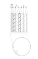
- FIG. 2 is a cross-sectional view of a part of the electrode group 18 (the outermost periphery (S)) closest to the side wall of the metal case.
- a negative electrode current collector 16b on the winding end side is arranged at the outermost periphery of the electrode group 18.
- the end of the winding of the negative electrode 16 is also the end of a surplus portion 16D that is wound around the outer surface of the negative electrode 16 on the inner side without passing through the positive electrode 15.
- the winding end side of the separator 17 may be further wrapped around the outermost outer surface of the negative electrode 16. Further, the outermost outer surface of the negative electrode 16 may be in contact with the inner surface of the side wall of the battery case 22.
- the outermost periphery of the electrode group 18 may be the positive electrode.
- the positive electrode and negative electrode in the explanation corresponding to FIG. 2 may be replaced. That is, when the positive electrode and the negative electrode are exchanged, the positive electrode current collector on the winding end side is arranged at the outermost periphery of the electrode group 18.
- the winding end of the positive electrode is also the end of the surplus portion that is wound around the outer surface of the positive electrode on the inner side without passing through the negative electrode.
- the winding end of the separator 17 is further wrapped around the outermost outer surface of the positive electrode to prevent contact between the outermost outer surface of the positive electrode and the inner surface of the side wall of the battery case 22 connected to the negative electrode. Ru.
- the surplus portion 16D has a functional layer 16c provided on the inner surface of the negative electrode current collector 16b.
- the functional layer 16c contains particulate matter that has functions such as heat insulation, heat absorption, and flame retardancy.
- the functional layer 16c is provided continuously from the end of the negative electrode active material layer 16a only on the inner surface of the negative electrode current collector 16b;
- the functional layer 16c may be provided on the outer surface of the electric body 16b, or may be provided intermittently on either surface.
- a negative electrode active material layer 16a is provided on the inner surface of the negative electrode 16 on the inner side of the circumference adjacent to the surplus portion 16D, but a negative electrode current collector 16b is exposed on the outer surface. Even when the battery is heated from the outside, the thermal diffusivity of the negative electrode current collector 16b helps prevent the battery case from becoming locally hot.
- a negative electrode active material layer 16a is provided on both surfaces of the negative electrode current collector 16b that is closer to the inside (two or more turns inside when viewed from the surplus portion 16D). However, the negative electrode active material layer 16a may also be provided on the outer surface of the negative electrode 16 one round inside from the outermost periphery (excess portion 16D). In addition, at the outermost periphery of the positive electrode 15, a positive electrode active material layer 15a is provided on the inner and outer surfaces of the positive electrode current collector 15b.
- the outermost peripheral portion (S) of the electrode group 18 is suppressed.
- the outermost peripheral part (S) is the part that is most likely to become the starting point of abnormal heat generation when the battery is heated from the outside. Therefore, suppressing the temperature rise at the outermost circumferential portion (S) and protecting the battery case 22 are important measures to prevent fire outbreaks.
- the surplus portion 16D is wrapped around the outer surface of the inner negative electrode 16 (negative electrode current collector 16b) via the separator 17.
- separator 17 when the separator 17 has a heat-resistant layer, the heat insulation effect becomes greater. That is, separator 17 may include a base material and a heat-resistant layer.
- the heat-resistant layer is an insulating layer formed on at least one main surface selected from the two main surfaces of the base material.
- the heat-resistant layer suppresses shrinkage of the base material when the temperature of the electrode group 18 rises excessively. Since the separator 17 includes the heat-resistant layer, shrinkage of the base material is suppressed, internal short circuits are less likely to occur, and temperature rise at the outermost circumference (S) is more effectively suppressed.
- the base material may be, for example, a porous membrane containing a polyolefin resin.
- Polyolefin resins are desirable because they are excellent in durability and have a function of closing the pores when the temperature rises to a certain level (that is, a shutdown function).
- the base material may have a single layer structure, a two layer structure, or a three or more layer structure.
- the heat-resistant layer may include inorganic particles (or inorganic filler) and a polymer (or polymer or resin).
- the polymer binds the inorganic particles to the substrate.
- As the polymer it is desirable to use a heat-resistant resin that has higher heat resistance than the main component of the base material.
- the heat-resistant layer may contain inorganic particles as a main component (for example, 80% by mass or more), or may contain a heat-resistant resin as a main component (for example, 40% by mass or more).
- the heat-resistant layer may not contain inorganic particles but may contain a heat-resistant resin.
- polyamide resin polyimide resin, polyamide-imide resin, etc.
- polyamide-imide resin polyamide-imide resin, etc.
- aromatic polyamide aromatic polyimide
- aromatic polyamide-imide aromatic polyamide-imide.
- These polymers are known to have particularly high heat resistance. From the viewpoint of heat resistance, aramids, ie, meta-aramids (meta-based wholly aromatic polyamides) and para-based aramids (para-based wholly aromatic polyamides) are preferred.
- the above-mentioned particulate materials that can be used in the functional layer 16d may be used.
- at least one selected from the group consisting of aluminum oxide, boehmite, talc, titanium oxide, and magnesium oxide is preferred in terms of insulation and heat resistance.
- the thickness of the heat-resistant layer may be 3% to 50% of the thickness of the separator 17.
- the heat-resistant layers are formed on each of the two main surfaces of the base material, their total may be 3% to 50% of the thickness of the separator.
- FIG. 3 is a conceptual diagram showing a cross-sectional structure of a battery 10A according to a second embodiment of the present disclosure.
- the surplus portion 16D is wrapped directly around the outer surface of the inner negative electrode 16 (negative electrode current collector 16b) without using the positive electrode 15 or the separator 17.
- the heat insulating effect, heat absorption effect, flame retardant effect, etc. of the functional layer 16c immediately act on the inner negative electrode 16 without intervening the separator 17.
- the functional layer 16c is directly attached to the outer surface of the inner negative electrode 16 (negative electrode current collector 16b) without intervening the separator 17. It is desirable that it be wrapped around the
- the outermost periphery of the electrode group 18 may be the positive electrode.
- the positive electrode and negative electrode in the explanation corresponding to FIG. 3 may be replaced. That is, when the positive electrode and the negative electrode are exchanged, in the battery 10A, the surplus portion is directly wrapped around the outer surface of the inner positive electrode (positive electrode current collector) without using the negative electrode or the separator. In this case, the heat insulating effect, heat absorption effect, flame retardant effect, etc. of the functional layer immediately act on the inner positive electrode without going through the separator. When the endothermic effect of the functional layer is expressed at the outermost peripheral portion (S), the functional layer may be directly wrapped around the outer surface of the inner positive electrode (positive electrode current collector) without using a separator.
- the negative electrode includes, for example, a negative electrode current collector and a negative electrode active material layer (negative electrode mixture layer) formed on the surface of the negative electrode current collector and containing a negative electrode active material.
- the negative electrode mixture layer can be formed by applying a negative electrode slurry in which the negative electrode mixture is dispersed in a dispersion medium onto the surface of the negative electrode current collector and drying it. The dried coating film may be rolled if necessary.
- the negative electrode mixture layer may be formed on one surface or both surfaces of the negative electrode current collector.
- the negative electrode mixture contains a negative electrode active material as an essential component, and can contain a binder, a conductive agent, a thickener, etc. as optional components.
- the negative electrode active material includes a material that electrochemically inserts and releases lithium ions.
- carbon materials, Si-containing materials, etc. can be used as the material that electrochemically absorbs and releases lithium ions.
- Si-containing material include silicon oxide (SiOx: 0.5 ⁇ x ⁇ 1.5), a composite material containing a silicate phase and silicon particles dispersed within the silicate phase, and the like.
- Examples of carbon materials include graphite, easily graphitizable carbon (soft carbon), and non-graphitizable carbon (hard carbon). Among these, graphite is preferable because it has excellent charging/discharging stability and low irreversible capacity.
- Graphite refers to a material having a graphite-type crystal structure, and includes natural graphite, artificial graphite, graphitized mesophase carbon particles, and the like. One type of carbon material may be used alone, or two or more types may be used in combination.
- a composite material containing a silicate phase and silicon particles dispersed within the silicate phase can easily achieve high capacity because the content of silicon particles can be arbitrarily selected.
- the silicate phase is a complex oxide phase containing silicon, oxygen, alkali metals, and the like.
- a composite material in which the silicate phase is a lithium silicate phase containing silicon, oxygen, and lithium will also be referred to as "LSX".
- LSX absorbs lithium ions by alloying silicon with lithium. By increasing the content of silicon particles, high capacity can be expected.
- the crystallite size of silicon particles dispersed within the lithium silicate phase is, for example, 5 nm or more. Silicon particles have a particulate phase of simple silicon (Si). When the crystallite size of the silicon particles is 5 nm or more, the surface area of the silicon particles can be kept small, so that deterioration of the silicon particles accompanied by generation of irreversible capacitance is less likely to occur.
- the crystallite size of a silicon particle is calculated from the half-width of a diffraction peak attributed to the Si (111) plane of an X-ray diffraction (XRD) pattern of the silicon particle using the Scherrer equation.
- LSX and a carbon material may be used in combination. Since the volume of LSX expands and contracts as it is charged and discharged, when its proportion in the negative electrode active material becomes large, poor contact between the negative electrode active material and the negative electrode current collector is likely to occur as the LSX is charged and discharged. On the other hand, by using LSX and a carbon material together, it is possible to achieve excellent cycle characteristics while imparting the high capacity of silicon particles to the negative electrode.
- the proportion of LSX in the total of LSX and carbon material is preferably 3 to 30% by mass, for example. This makes it easier to achieve both higher capacity and improved cycle characteristics.
- negative electrode current collector metal foil, mesh body, net body, punched sheet, etc. are used.
- Examples of the material of the negative electrode current collector include stainless steel, nickel, nickel alloy, copper, and copper alloy.
- a resin material is used as the binder for the negative electrode.
- the binder include fluororesins, polyolefin resins, polyamide resins, polyimide resins, acrylic resins, vinyl resins, rubber-like materials (for example, styrene-butadiene copolymer (SBR)), and the like.
- SBR styrene-butadiene copolymer
- One type of binder may be used alone, or two or more types may be used in combination.
- thickener examples include cellulose derivatives such as cellulose ether.
- examples of cellulose derivatives include carboxymethylcellulose (CMC), modified products thereof, and methylcellulose.
- CMC carboxymethylcellulose
- One type of thickener may be used alone, or two or more types may be used in combination.
- Examples of the conductive material include carbon nanotubes (CNT), carbon fibers other than CNT, and conductive particles (eg, carbon black, graphite).
- CNT carbon nanotubes
- carbon fibers other than CNT carbon fibers other than CNT
- conductive particles eg, carbon black, graphite
- the dispersion medium used in the negative electrode slurry is not particularly limited, and examples thereof include water, alcohol, N-methyl-2-pyrrolidone (NMP), and mixed solvents thereof.
- the negative electrode current collector for example, metal foil can be used.
- the negative electrode current collector may be porous.
- Examples of the material of the negative electrode current collector include stainless steel, nickel, nickel alloy, copper, and copper alloy.
- the thickness of the negative electrode current collector is not particularly limited, but is, for example, 1 to 50 ⁇ m, and may be 5 to 30 ⁇ m.
- the positive electrode includes, for example, a positive electrode current collector and a positive electrode active material layer (positive electrode mixture layer) formed on the surface of the positive electrode current collector and containing a positive electrode active material.
- the positive electrode mixture layer can be formed by applying a positive electrode slurry in which the positive electrode mixture is dispersed in a dispersion medium onto the surface of the positive electrode current collector and drying the slurry. The dried coating film may be rolled if necessary.
- the positive electrode mixture layer may be formed on one surface or both surfaces of the positive electrode current collector.
- the positive electrode mixture contains a positive electrode active material as an essential component, and may contain a binder, a thickener, etc. as optional components.
- the positive electrode active material may be any material that can be used as a positive electrode active material for non-aqueous electrolyte secondary batteries (particularly lithium ion secondary batteries), but from the viewpoint of increasing capacity, lithium transition metals containing at least nickel as a transition metal are preferred.
- the proportion of the composite oxide N in the positive electrode active material is, for example, 70% by mass or more, may be 90% by mass or more, or may be 95% by mass or more.
- the composite oxide N may be, for example, a lithium transition metal composite oxide that has a layered rock salt type structure and includes Ni and at least one selected from the group consisting of Co, Mn, and Al.
- it has a layered rock salt type structure and contains Ni and at least one member selected from the group consisting of Co, Mn, and Al, and the proportion of Ni in metal elements other than Li is 80 atomic % or more
- the lithium transition metal composite oxide is also referred to as "composite oxide HN.”
- the proportion of the composite oxide HN in the composite oxide N used as the positive electrode active material is, for example, 90% by mass or more, may be 95% by mass or more, or may be 100%. The higher the proportion of Ni, the more lithium ions can be extracted from the composite oxide HN during charging, and the capacity can be increased.
- Co, Mn, and Al contribute to stabilizing the crystal structure of the composite oxide HN with a high Ni content.
- the composite oxide HN is represented by the formula: Li ⁇ Ni (1-x1-x2-yz) Co x1 Mn x2 Al y M z O 2+ ⁇ , for example.
- Element M is an element other than Li, Ni, Co, Mn, Al, and oxygen.
- Mn contributes to stabilizing the crystal structure of the composite oxide HN, and since the composite oxide HN contains inexpensive Mn, it is advantageous for cost reduction.
- Al contributes to stabilizing the crystal structure of the composite oxide HN.
- ⁇ indicating the atomic ratio of lithium is, for example, 0.95 ⁇ 1.05. ⁇ increases and decreases with charging and discharging. In (2+ ⁇ ) indicating the atomic ratio of oxygen, ⁇ satisfies -0.05 ⁇ 0.05.
- x1, which indicates the atomic ratio of Co is, for example, 0.1 or less (0 ⁇ x1 ⁇ 0.1)
- x2, which indicates the atomic ratio of Mn is, for example, 0.1 or less (0 ⁇ x2 ⁇ 0.1).
- y indicating the atomic ratio of Al is, for example, 0.1 or less (0 ⁇ y ⁇ 0.1)
- z indicating the atomic ratio of the element M is, for example, 0 ⁇ z ⁇ 0.10. It is.
- the element M may be at least one selected from the group consisting of Ti, Zr, Nb, Mo, W, Fe, Zn, B, Si, Mg, Ca, Sr, Sc, and Y.
- the surface structure of the composite oxide HN is stabilized, the resistance is reduced, and metal elution is further reduced. It is thought that this can be suppressed.
- Element M is more effective if it is unevenly distributed near the particle surface of the composite oxide HN.
- binder for the positive electrode for example, a resin material is used.
- the binder include fluororesin, polyolefin resin, polyamide resin, polyimide resin, acrylic resin, and vinyl resin.
- One type of binder may be used alone, or two or more types may be used in combination.
- Examples of the conductive material include carbon nanotubes (CNT), carbon fibers other than CNT, and conductive particles (eg, carbon black, graphite).
- CNT carbon nanotubes
- carbon fibers other than CNT carbon fibers other than CNT
- conductive particles eg, carbon black, graphite
- the dispersion medium used in the positive electrode slurry is not particularly limited, and examples include water, alcohol, N-methyl-2-pyrrolidone (NMP), and mixed solvents thereof.
- the positive electrode current collector may be porous.
- the porous current collector include a net, a punched sheet, and an expanded metal.
- the material for the positive electrode current collector include stainless steel, aluminum, aluminum alloy, and titanium.
- the thickness of the positive electrode current collector is not particularly limited, but is, for example, 1 to 50 ⁇ m, and may be 5 to 30 ⁇ m.
- the non-aqueous electrolyte includes a non-aqueous solvent and a solute dissolved in the non-aqueous solvent.
- a solute is an electrolyte salt that ionically dissociates in a non-aqueous electrolyte.
- the solute includes a lithium salt.
- the non-aqueous electrolyte may contain various additives.
- cyclic carbonate for example, cyclic carbonate, chain carbonate, cyclic carboxylic acid ester, chain carboxylic ester, etc. are used.
- cyclic carbonate examples include propylene carbonate (PC), ethylene carbonate (EC), vinylene carbonate (VC), and the like.
- chain carbonate esters examples include diethyl carbonate (DEC), ethylmethyl carbonate (EMC), and dimethyl carbonate (DMC).
- examples of the cyclic carboxylic acid ester include ⁇ -butyrolactone (GBL) and ⁇ -valerolactone (GVL).
- chain carboxylic acid esters examples include methyl acetate, ethyl acetate, propyl acetate, methyl propionate (MP), and ethyl propionate (EP).
- the non-aqueous solvents may be used alone or in combination of two or more.
- lithium salts include lithium salts of chlorine-containing acids (LiClO 4 , LiAlCl 4 , LiB 10 Cl 10 , etc.), lithium salts of fluorine-containing acids (LiPF 6 , LiPF 2 O 2 , LiBF 4 , LiSbF 6 , LiAsF 6 , LiCF 3 SO 3 , LiCF 3 CO 2 etc.), lithium salts of fluorine-containing acid imides (LiN(FSO 2 ) 2 , LiN(CF 3 SO 2 ) 2 , LiN(CF 3 SO 2 )(C 4 F 9 SO 2 ), LiN (C 2 F 5 SO 2 ) 2 , etc.), lithium halide (LiCl, LiBr, LiI, etc.), etc. can be used.
- One type of lithium salt may be used alone, or two or more types may be used in combination.
- the concentration of the lithium salt in the non-aqueous electrolyte may be 1 mol/liter or more and 2 mol/liter or less, or 1 mol/liter or more and 1.5 mol/liter or less.
- the lithium salt concentration is not limited to the above.
- the separator has high ion permeability, appropriate mechanical strength, and insulation properties.
- a microporous thin film, woven fabric, nonwoven fabric, etc. can be used, and for example, a separator having a heat-resistant layer as described above may be used. (Additional note) The following techniques are disclosed by the description of the above embodiments.
- An electrode group including a first electrode having a first current collector, a second electrode having a second current collector, and a separator interposed between the first electrode and the second electrode; comprising an electrolyte, a battery case accommodating the electrode group and the non-aqueous electrolyte,
- the first electrode and the second electrode are wound together with the separator in between, and the outermost periphery of the first electrode is disposed outside the outermost periphery of the second electrode,
- the end of the winding of the first electrode is an end of a surplus portion that is wound around the outer surface of the first electrode on the inner side without passing through the second electrode,
- a length L1 of the surplus portion along the circumferential direction is 90% or more of a circumferential length L of the first electrode at the outermost periphery,
- a non-aqueous electrolyte secondary battery wherein the surplus portion has a functional layer provided on a surface of the first current collector.
- the non-aqueous electrolyte secondary battery according to technique 1 wherein at least a part of the surplus portion is wrapped around the outer surface of the first electrode on the inner side without further intervening the separator.
- the first electrode includes a first active material layer provided on the surface of the first current collector, The nonaqueous electrolyte secondary battery according to any one of Techniques 1 to 3, wherein the thickness of the functional layer is equal to or less than the thickness of the first active material layer.
- the non-aqueous electrolyte secondary battery according to any one of Techniques 1 to 7, wherein the functional layer includes at least one of organic particles and inorganic particles.
- the inorganic particles are the non-aqueous electrolyte diode according to technique 8, including at least one selected from the group consisting of metal oxides, metal hydroxides, metal nitrides, metal fluorides, metal borides, and metal carbides.
- the metal oxide includes at least one selected from the group consisting of aluminum oxide, titanium oxide, magnesium oxide, zirconium oxide, nickel oxide, silicon oxide, and manganese oxide
- the metal hydroxide includes at least one selected from the group consisting of boehmite, aluminum hydroxide, and magnesium hydroxide
- the metal nitride includes at least one selected from the group consisting of titanium nitride, boron nitride, aluminum nitride, magnesium nitride, and silicon nitride
- the metal fluoride includes at least one selected from the group consisting of aluminum fluoride, lithium fluoride, sodium fluoride, magnesium fluoride, calcium fluoride, and barium fluoride
- the metal boride includes titanium boride, The nonaqueous electrolyte secondary battery according to technique 9, wherein the metal carbide includes at least one selected from the group consisting of silicon carbide, boron carbide, titanium carbide, and tungsten carbide.
- the flame retardants include ethylene-1,2-bispentabromophenyl, ethylene bistetrabromophthalimide, tetrabisbromobisphenol A, hexabromocyclododecane, 2,4,6-tribromophenol, 1,6,7,8 ,9,14,15,16,17,17,18,18-dodecachloropentacyclo(12.2.1.16,9.02,13.05,10)octadeca-7,15-diene and tris(
- the first electrode is a negative electrode, The non-aqueous electrolyte secondary battery according to any one of Techniques 1 to 12, wherein the first current collector contains Cu.
- the first electrode is a positive electrode, The nonaqueous electrolyte secondary battery according to any one of Techniques 1 to 12, wherein the first current collector includes at least one selected from the group consisting of Al, Ti, and stainless steel.
- Examples 1 to 45 ⁇ (a) Preparation of positive electrode 100 parts by mass of positive electrode active material (LiNi 0.92 Co 0.04 Al 0.04 O 2 ), 1.0 parts by mass of acetylene black as a conductive material, and polyvinylidene fluoride (PVdF) as a binder.
- a positive electrode slurry was prepared by mixing with N-methyl-2-pyrrolidone (NMP). The amount of PVdF was 0.9 parts by mass per 100 parts by mass of the positive electrode active material.
- NMP N-methyl-2-pyrrolidone
- the amount of PVdF was 0.9 parts by mass per 100 parts by mass of the positive electrode active material.
- the thickness of the two positive electrode active material layers attached to both surfaces of the positive electrode current collector was 70 ⁇ m. Thereafter, the positive electrode was cut into strips.
- the positive electrode active material layer was provided only on the inner periphery side of the positive electrode current collector on the inner periphery side that faces the surplus portion.
- the amount of SBR was 1.0 parts by mass per 100 parts by mass of the negative electrode active material.
- the thickness of the two negative electrode active material layers attached to both surfaces of the negative electrode current collector was 70 ⁇ m. Thereafter, the negative electrode was cut into strips. Note that when the negative electrode constitutes the outermost periphery, a negative electrode active material layer was provided only on the inner periphery side of the negative electrode current collector on the inner periphery side that faces the surplus portion.
- a predetermined surplus portion was formed on the first electrode (negative electrode or positive electrode).
- the length L1 of the excess portion along the circumferential direction of the electrode group is 100% (one circumference of the outermost circumference) or approximately 400% (four circumferences from the outermost circumference) of the circumferential length L of the outermost negative electrode or positive electrode. minutes).
- the functional layer was provided only on the inner circumferential side, only on the outer circumferential side, or on both sides of the current collector (copper foil or aluminum foil).
- a cylindrical lithium ion secondary battery as shown in FIG. 1 was produced according to the following procedure.
- An upper insulating plate and a lower insulating plate were arranged on the upper and lower end surfaces of the electrode group, and the electrode group was housed in a battery case (side wall thickness: 220 ⁇ m) made of steel (SPCE) and having an opening and a bottomed cylinder.
- the negative electrode lead was welded to the inside of the bottom of the battery case.
- an annular groove was formed above the upper insulating plate and near the open end of the battery case.
- a nonaqueous electrolyte is injected into the battery case under reduced pressure, and then the sealing plate is placed in the annular groove so as to close the opening of the battery case. I placed it.
- a gasket was previously placed on the peripheral edge of the sealing plate, and the open end of the battery case was caulked to the sealing plate via this gasket, thereby completing a cylindrical 21700 size lithium ion secondary battery.
- the completed lithium ion secondary battery is charged to 4.2V with a constant current equivalent to 0.3C, and then pre-charged and discharged to 2.5V with a constant current equivalent to 0.5C, which corresponds to the initial state.
- a lithium ion secondary battery was obtained.
- a negative electrode active material layer having the same thickness as the negative electrode active material layer in the portion facing the positive electrode active material layer was provided as a functional layer only on the inner peripheral side of the negative electrode current collector.
- a negative electrode active material layer having the same thickness as the negative electrode active material layer in the portion facing the positive electrode active material layer was provided as a functional layer only on the outer peripheral side of the negative electrode current collector.
- negative electrode active material layers having the same thickness as the negative electrode active material layer of the portion facing the positive electrode active material layer were provided as functional layers on both sides of the negative electrode current collector.
- Example 19 100 parts by mass of aluminum oxide (average particle size 0.7 ⁇ m) and 2 parts by mass of binder (PVdF (the same applies hereinafter)) were added as a functional layer (thickness 70 ⁇ m) only on the inner peripheral side of the negative electrode current collector. A coating film containing parts was provided.
- Example 20 a coating film containing 100 parts by mass of titanium oxide (average particle size 0.5 ⁇ m) and 2 parts by mass of a binder was provided as a functional layer (thickness 70 ⁇ m) only on the inner peripheral side of the negative electrode current collector. Ta.
- Example 21 the flame retardant ethylene-1,2-bispentabromophenyl (SAYTEX (registered trademark) manufactured by Albemarle Japan Co., Ltd.) was applied as a functional layer (thickness 70 ⁇ m) only on the inner peripheral side of the negative electrode current collector.
- a coating film containing 100 parts by mass of -8010) and 2 parts by mass of a binder was provided.
- Example 22 a negative electrode active material layer having the same thickness as the negative electrode active material layer in the portion facing the positive electrode active material layer was provided as a functional layer on the inner peripheral side of the negative electrode current collector, and A coating film containing the same aluminum oxide as in Example 19 was provided on the side.
- Example 23 a negative electrode active material layer having the same thickness as the negative electrode active material layer in the portion facing the positive electrode active material layer was provided as a functional layer on the inner peripheral side of the negative electrode current collector, and A coating film containing the same titanium oxide as in Example 20 was provided on the side.
- Example 24 a negative electrode active material layer having the same thickness as the negative electrode active material layer in the portion facing the positive electrode active material layer was provided as a functional layer on the inner peripheral side of the negative electrode current collector, and A coating film containing the same flame retardant as in Example 21 was provided on the side.
- Example 25 a coating film containing the same aluminum oxide as in Example 19 was provided as a functional layer only on the inner peripheral side of the positive electrode current collector. A separator was further wrapped around the outermost surface of the positive electrode to ensure insulation between the outermost surface of the positive electrode and the battery case. The same applies to Examples 30 to 45 below.
- Example 30 to 35 a coating film containing the same aluminum oxide as in Example 19 was provided as a functional layer only on the outer peripheral side of the positive electrode current collector.
- Example 36 to 41 a coating film containing the same aluminum oxide as in Example 19 was provided as a functional layer on both sides of the positive electrode current collector.
- Example 42 a coating film containing the same titanium oxide as in Example 20 was provided as a functional layer only on the inner peripheral side of the positive electrode current collector.
- Example 43 a coating film containing the same flame retardant as in Example 21 was provided as a functional layer only on the inner peripheral side of the positive electrode current collector.
- Example 44 a coating film containing the same aluminum oxide as in Example 19 was provided as a functional layer on the inner circumferential side of the positive electrode current collector, and the same titanium oxide as in Example 20 was provided on the outer circumferential side of the positive electrode current collector. A coating film containing the material was provided.
- Example 45 a coating film containing the same aluminum oxide as in Example 19 was provided as a functional layer on the inner circumferential side of the positive electrode current collector, and the same flame retardant as in Example 21 was provided on the outer circumferential side of the positive electrode current collector.
- a coating film containing the material was provided.
- the entire excess portion was wrapped around the outer surface of the inner first electrode via a separator. In another example, the entire excess portion was wrapped around the outer surface of the inner first electrode without using a separator.
- the functional layer was provided not on the entire surface of the current collector but on the half surface on the sealing body side.
- the functional layer was provided not on the entire surface of the current collector but on the bottom half surface of the battery case.
- the functional layer was provided not on the entire surface of the current collector, but in a stripe shape (width: 10 mm, interval: 3 mm) along the circumferential direction.
- the evaluation results are shown in Table 1.
- the batteries of Examples 1 to 45 are batteries A1 to A45, and the battery of Comparative Example 1 is battery B1.
- the discharge capacity of the batteries of each example is a relative ratio when the discharge capacity of battery B1 is taken as 100%.
- the ratio (R) tended to be smaller than when it was provided on the bottom side. This is thought to be because the sealing body side, which is the outlet side of the high-temperature gas, tends to be hotter than the bottom side, and it is more effective to arrange the functional layer on the sealing body side.
- the ratio (R) tended to be smaller than when it was provided in a stripe shape along the circumferential direction. This is considered to be because, in the case of a striped shape, there is an uncoated portion of the functional layer on the current collector on the side of the sealing body, which is the outlet side of the high-temperature gas.
- the ratio (R) tended to be smaller than when it was provided on the bottom side. This can be said to be proof of the effectiveness of providing the functional layer on the sealing body side of the current collector.
- the nonaqueous electrolyte secondary battery according to the present disclosure is useful as a main power source for mobile communication devices, portable electronic devices, electric vehicles, and the like.
- Nonaqueous electrolyte secondary battery 11 Sealing body 12
- Valve body 13 Metal plate 14
- Insulating member 15 Positive electrode 15L Positive electrode lead 15b
- Positive electrode active material layer 16 Negative electrode 16L Negative electrode lead 16b
- Negative electrode current collector 16c Negative electrode active material layer 16d
- Functional layer 16D Surplus portion 17
- Separator 18 Electrode group 21 Gasket 22 Battery case 22a Groove
Landscapes
- Chemical & Material Sciences (AREA)
- Chemical Kinetics & Catalysis (AREA)
- Electrochemistry (AREA)
- General Chemical & Material Sciences (AREA)
- Engineering & Computer Science (AREA)
- Materials Engineering (AREA)
- Manufacturing & Machinery (AREA)
- Composite Materials (AREA)
- Secondary Cells (AREA)
Priority Applications (4)
| Application Number | Priority Date | Filing Date | Title |
|---|---|---|---|
| CN202380033543.0A CN119054126A (zh) | 2022-04-14 | 2023-04-05 | 非水电解质二次电池 |
| EP23788244.4A EP4510288A4 (en) | 2022-04-14 | 2023-04-05 | SECONDARY BATTERY WITH NON-AQUEOUS ELECTROLYTE |
| US18/855,091 US20250253412A1 (en) | 2022-04-14 | 2023-04-05 | Non-aqueous electrolyte secondary battery |
| JP2024514923A JPWO2023199825A1 (https=) | 2022-04-14 | 2023-04-05 |
Applications Claiming Priority (2)
| Application Number | Priority Date | Filing Date | Title |
|---|---|---|---|
| JP2022066869 | 2022-04-14 | ||
| JP2022-066869 | 2022-04-14 |
Publications (1)
| Publication Number | Publication Date |
|---|---|
| WO2023199825A1 true WO2023199825A1 (ja) | 2023-10-19 |
Family
ID=88329708
Family Applications (1)
| Application Number | Title | Priority Date | Filing Date |
|---|---|---|---|
| PCT/JP2023/014109 Ceased WO2023199825A1 (ja) | 2022-04-14 | 2023-04-05 | 非水電解質二次電池 |
Country Status (5)
| Country | Link |
|---|---|
| US (1) | US20250253412A1 (https=) |
| EP (1) | EP4510288A4 (https=) |
| JP (1) | JPWO2023199825A1 (https=) |
| CN (1) | CN119054126A (https=) |
| WO (1) | WO2023199825A1 (https=) |
Citations (4)
| Publication number | Priority date | Publication date | Assignee | Title |
|---|---|---|---|---|
| JP2003297432A (ja) | 2002-04-04 | 2003-10-17 | Sony Corp | 非水電解質二次電池 |
| JP2006286496A (ja) * | 2005-04-04 | 2006-10-19 | Sony Corp | ポリマー電池 |
| JP2009211857A (ja) * | 2008-03-03 | 2009-09-17 | Sony Corp | 電池 |
| WO2013014833A1 (ja) * | 2011-07-25 | 2013-01-31 | パナソニック株式会社 | リチウムイオン二次電池 |
-
2023
- 2023-04-05 WO PCT/JP2023/014109 patent/WO2023199825A1/ja not_active Ceased
- 2023-04-05 EP EP23788244.4A patent/EP4510288A4/en active Pending
- 2023-04-05 US US18/855,091 patent/US20250253412A1/en active Pending
- 2023-04-05 CN CN202380033543.0A patent/CN119054126A/zh active Pending
- 2023-04-05 JP JP2024514923A patent/JPWO2023199825A1/ja active Pending
Patent Citations (4)
| Publication number | Priority date | Publication date | Assignee | Title |
|---|---|---|---|---|
| JP2003297432A (ja) | 2002-04-04 | 2003-10-17 | Sony Corp | 非水電解質二次電池 |
| JP2006286496A (ja) * | 2005-04-04 | 2006-10-19 | Sony Corp | ポリマー電池 |
| JP2009211857A (ja) * | 2008-03-03 | 2009-09-17 | Sony Corp | 電池 |
| WO2013014833A1 (ja) * | 2011-07-25 | 2013-01-31 | パナソニック株式会社 | リチウムイオン二次電池 |
Non-Patent Citations (1)
| Title |
|---|
| See also references of EP4510288A4 |
Also Published As
| Publication number | Publication date |
|---|---|
| US20250253412A1 (en) | 2025-08-07 |
| CN119054126A (zh) | 2024-11-29 |
| EP4510288A4 (en) | 2025-11-26 |
| JPWO2023199825A1 (https=) | 2023-10-19 |
| EP4510288A1 (en) | 2025-02-19 |
Similar Documents
| Publication | Publication Date | Title |
|---|---|---|
| US8637177B2 (en) | Electrochemical device | |
| CN104937754B (zh) | 正极活性物质和使用该活性物质的锂二次电池 | |
| KR102129497B1 (ko) | 리튬 이온 2차 전지 | |
| JP6016038B2 (ja) | 非水電解質二次電池 | |
| US20130157096A1 (en) | Non-aqueous electrolyte secondary battery and method for producing the same | |
| JP5614597B2 (ja) | 非水電解質二次電池 | |
| KR20140085337A (ko) | 리튬 이차 전지 | |
| WO2010053058A1 (ja) | 電気化学素子 | |
| JP2026067938A (ja) | 二次電池 | |
| WO2020017581A1 (ja) | 非水電解質蓄電素子、及び蓄電装置 | |
| WO2012120579A1 (ja) | 非水電解質二次電池 | |
| US12218342B2 (en) | Energy storage device | |
| EP4704165A1 (en) | Positive electrode for secondary battery, and secondary battery | |
| WO2023199825A1 (ja) | 非水電解質二次電池 | |
| US20250309470A1 (en) | Non-aqueous electrolyte secondary battery | |
| JP5213003B2 (ja) | 非水電解質二次電池 | |
| JP2009295554A (ja) | 電池 | |
| JP6631535B2 (ja) | リチウムイオン電池 | |
| WO2023182341A1 (ja) | 非水電解質二次電池 | |
| JP5129412B2 (ja) | 非水電解質二次電池及びその製造方法 | |
| JP2016058180A (ja) | リチウムイオン二次電池 | |
| EP4379895A1 (en) | Non-aqueous electrolyte secondary battery | |
| WO2025169975A1 (ja) | 二次電池 | |
| JP2000100472A (ja) | 非水電解液二次電池 |
Legal Events
| Date | Code | Title | Description |
|---|---|---|---|
| 121 | Ep: the epo has been informed by wipo that ep was designated in this application |
Ref document number: 23788244 Country of ref document: EP Kind code of ref document: A1 |
|
| WWE | Wipo information: entry into national phase |
Ref document number: 2024514923 Country of ref document: JP Ref document number: 18855091 Country of ref document: US |
|
| WWE | Wipo information: entry into national phase |
Ref document number: 202380033543.0 Country of ref document: CN |
|
| WWE | Wipo information: entry into national phase |
Ref document number: 202417085198 Country of ref document: IN |
|
| WWE | Wipo information: entry into national phase |
Ref document number: 2023788244 Country of ref document: EP |
|
| NENP | Non-entry into the national phase |
Ref country code: DE |
|
| ENP | Entry into the national phase |
Ref document number: 2023788244 Country of ref document: EP Effective date: 20241114 |
|
| WWP | Wipo information: published in national office |
Ref document number: 18855091 Country of ref document: US |