WO2023191000A1 - ベーパーチャンバ用の本体シート、ベーパーチャンバおよび電子機器 - Google Patents
ベーパーチャンバ用の本体シート、ベーパーチャンバおよび電子機器 Download PDFInfo
- Publication number
- WO2023191000A1 WO2023191000A1 PCT/JP2023/013416 JP2023013416W WO2023191000A1 WO 2023191000 A1 WO2023191000 A1 WO 2023191000A1 JP 2023013416 W JP2023013416 W JP 2023013416W WO 2023191000 A1 WO2023191000 A1 WO 2023191000A1
- Authority
- WO
- WIPO (PCT)
- Prior art keywords
- land
- body surface
- intersection
- main body
- groove
- Prior art date
- Legal status (The legal status is an assumption and is not a legal conclusion. Google has not performed a legal analysis and makes no representation as to the accuracy of the status listed.)
- Ceased
Links
Images












































Classifications
-
- H—ELECTRICITY
- H10—SEMICONDUCTOR DEVICES; ELECTRIC SOLID-STATE DEVICES NOT OTHERWISE PROVIDED FOR
- H10W—GENERIC PACKAGES, INTERCONNECTIONS, CONNECTORS OR OTHER CONSTRUCTIONAL DETAILS OF DEVICES COVERED BY CLASS H10
- H10W40/00—Arrangements for thermal protection or thermal control
- H10W40/40—Arrangements for thermal protection or thermal control involving heat exchange by flowing fluids
-
- H—ELECTRICITY
- H10—SEMICONDUCTOR DEVICES; ELECTRIC SOLID-STATE DEVICES NOT OTHERWISE PROVIDED FOR
- H10W—GENERIC PACKAGES, INTERCONNECTIONS, CONNECTORS OR OTHER CONSTRUCTIONAL DETAILS OF DEVICES COVERED BY CLASS H10
- H10W40/00—Arrangements for thermal protection or thermal control
- H10W40/70—Fillings or auxiliary members in containers or in encapsulations for thermal protection or control
- H10W40/73—Fillings or auxiliary members in containers or in encapsulations for thermal protection or control for cooling by change of state
-
- F—MECHANICAL ENGINEERING; LIGHTING; HEATING; WEAPONS; BLASTING
- F28—HEAT EXCHANGE IN GENERAL
- F28D—HEAT-EXCHANGE APPARATUS, NOT PROVIDED FOR IN ANOTHER SUBCLASS, IN WHICH THE HEAT-EXCHANGE MEDIA DO NOT COME INTO DIRECT CONTACT
- F28D15/00—Heat-exchange apparatus with the intermediate heat-transfer medium in closed tubes passing into or through the conduit walls ; Heat-exchange apparatus employing intermediate heat-transfer medium or bodies
- F28D15/02—Heat-exchange apparatus with the intermediate heat-transfer medium in closed tubes passing into or through the conduit walls ; Heat-exchange apparatus employing intermediate heat-transfer medium or bodies in which the medium condenses and evaporates, e.g. heat pipes
-
- F—MECHANICAL ENGINEERING; LIGHTING; HEATING; WEAPONS; BLASTING
- F28—HEAT EXCHANGE IN GENERAL
- F28D—HEAT-EXCHANGE APPARATUS, NOT PROVIDED FOR IN ANOTHER SUBCLASS, IN WHICH THE HEAT-EXCHANGE MEDIA DO NOT COME INTO DIRECT CONTACT
- F28D15/00—Heat-exchange apparatus with the intermediate heat-transfer medium in closed tubes passing into or through the conduit walls ; Heat-exchange apparatus employing intermediate heat-transfer medium or bodies
- F28D15/02—Heat-exchange apparatus with the intermediate heat-transfer medium in closed tubes passing into or through the conduit walls ; Heat-exchange apparatus employing intermediate heat-transfer medium or bodies in which the medium condenses and evaporates, e.g. heat pipes
- F28D15/04—Heat-exchange apparatus with the intermediate heat-transfer medium in closed tubes passing into or through the conduit walls ; Heat-exchange apparatus employing intermediate heat-transfer medium or bodies in which the medium condenses and evaporates, e.g. heat pipes with tubes having a capillary structure
-
- H—ELECTRICITY
- H05—ELECTRIC TECHNIQUES NOT OTHERWISE PROVIDED FOR
- H05K—PRINTED CIRCUITS; CASINGS OR CONSTRUCTIONAL DETAILS OF ELECTRIC APPARATUS; MANUFACTURE OF ASSEMBLAGES OF ELECTRICAL COMPONENTS
- H05K7/00—Constructional details common to different types of electric apparatus
- H05K7/20—Modifications to facilitate cooling, ventilating, or heating
- H05K7/2029—Modifications to facilitate cooling, ventilating, or heating using a liquid coolant with phase change in electronic enclosures
- H05K7/20327—Accessories for moving fluid, for connecting fluid conduits, for distributing fluid or for preventing leakage, e.g. pumps, tanks or manifolds
-
- H—ELECTRICITY
- H05—ELECTRIC TECHNIQUES NOT OTHERWISE PROVIDED FOR
- H05K—PRINTED CIRCUITS; CASINGS OR CONSTRUCTIONAL DETAILS OF ELECTRIC APPARATUS; MANUFACTURE OF ASSEMBLAGES OF ELECTRICAL COMPONENTS
- H05K7/00—Constructional details common to different types of electric apparatus
- H05K7/20—Modifications to facilitate cooling, ventilating, or heating
- H05K7/2029—Modifications to facilitate cooling, ventilating, or heating using a liquid coolant with phase change in electronic enclosures
- H05K7/20336—Heat pipes, e.g. wicks or capillary pumps
-
- H—ELECTRICITY
- H10—SEMICONDUCTOR DEVICES; ELECTRIC SOLID-STATE DEVICES NOT OTHERWISE PROVIDED FOR
- H10W—GENERIC PACKAGES, INTERCONNECTIONS, CONNECTORS OR OTHER CONSTRUCTIONAL DETAILS OF DEVICES COVERED BY CLASS H10
- H10W40/00—Arrangements for thermal protection or thermal control
- H10W40/20—Arrangements for cooling
- H10W40/22—Arrangements for cooling characterised by their shape, e.g. having conical or cylindrical projections
-
- H—ELECTRICITY
- H10—SEMICONDUCTOR DEVICES; ELECTRIC SOLID-STATE DEVICES NOT OTHERWISE PROVIDED FOR
- H10W—GENERIC PACKAGES, INTERCONNECTIONS, CONNECTORS OR OTHER CONSTRUCTIONAL DETAILS OF DEVICES COVERED BY CLASS H10
- H10W40/00—Arrangements for thermal protection or thermal control
- H10W40/20—Arrangements for cooling
- H10W40/22—Arrangements for cooling characterised by their shape, e.g. having conical or cylindrical projections
- H10W40/226—Arrangements for cooling characterised by their shape, e.g. having conical or cylindrical projections characterised by projecting parts, e.g. fins to increase surface area
-
- H—ELECTRICITY
- H10—SEMICONDUCTOR DEVICES; ELECTRIC SOLID-STATE DEVICES NOT OTHERWISE PROVIDED FOR
- H10W—GENERIC PACKAGES, INTERCONNECTIONS, CONNECTORS OR OTHER CONSTRUCTIONAL DETAILS OF DEVICES COVERED BY CLASS H10
- H10W40/00—Arrangements for thermal protection or thermal control
- H10W40/20—Arrangements for cooling
- H10W40/22—Arrangements for cooling characterised by their shape, e.g. having conical or cylindrical projections
- H10W40/226—Arrangements for cooling characterised by their shape, e.g. having conical or cylindrical projections characterised by projecting parts, e.g. fins to increase surface area
- H10W40/228—Arrangements for cooling characterised by their shape, e.g. having conical or cylindrical projections characterised by projecting parts, e.g. fins to increase surface area the projecting parts being wire-shaped or pin-shaped
Definitions
- the present disclosure relates to a main body sheet for a vapor chamber, a vapor chamber, and an electronic device.
- Electronic equipment such as mobile terminals uses electronic devices that generate heat. Examples of such electronic devices include central processing units (CPUs), light emitting diodes (LEDs), power semiconductors, and the like. Examples of mobile terminals include portable terminals and tablet terminals.
- CPUs central processing units
- LEDs light emitting diodes
- power semiconductors and the like.
- mobile terminals include portable terminals and tablet terminals.
- Such electronic devices are cooled by a heat dissipation device such as a heat pipe (see, for example, Patent Document 1).
- a heat dissipation device such as a heat pipe
- vapor chambers that can be made thinner than heat pipes are being developed. The vapor chamber cools the electronic device by allowing the enclosed working fluid to absorb the heat of the electronic device and diffuse it therein.
- the working fluid in the vapor chamber receives heat from the electronic device at a portion (evaporation section) close to the electronic device.
- the working fluid receives heat and evaporates into working steam.
- the working vapor is diffused in a direction away from the evaporation section within a vapor flow path section formed within the vapor chamber.
- the diffused working vapor is cooled and condensed to become working fluid.
- a liquid flow path section serving as a capillary structure (wick) is provided within the vapor chamber.
- the working fluid flows through the liquid flow path section and is transported toward the evaporation section.
- the working fluid transported to the evaporator receives heat again in the evaporator and evaporates.
- the working fluid circulates within the vapor chamber through repeated phase changes, ie, evaporation and condensation, thereby diffusing and discharging heat from the electronic device.
- a vapor chamber configured in this manner is required to have improved heat dissipation performance.
- An object of the present disclosure is to provide a main body sheet for a vapor chamber, a vapor chamber, and an electronic device that can improve heat dissipation performance.
- This disclosure includes: A main body sheet for a vapor chamber in which a working fluid is sealed, a first body surface; a second body surface located on the opposite side of the first body surface; a space penetrating from the first body surface to the second body surface; a first land portion around which the space portion is located, the first land portion extending from the first body surface to the second body surface and extending in a first direction in plan view; a first mainstream groove located on the first main body surface of the first land portion, the first mainstream groove communicating with the space and extending in the first direction; a second land portion around which the space portion is located, the second land portion extending from the first body surface to the second body surface and extending in a second direction different from the first direction in plan view; , a second mainstream groove located on the first main body surface of the second land portion, the second mainstream groove communicating with the space and extending in the second direction; a land intersection portion where the first land portion and the second land portion intersect, At the land intersection portion, the first mainstream groove and the second mainstream groove
- This disclosure includes: The first land portion extends in the first direction beyond the land intersection portion, The second land portion extends in the second direction beyond the land intersection portion.
- the main body sheet for a vapor chamber described in [1] may also be used.
- This disclosure includes: The land intersection portion extends from the first body surface to the second body surface,
- the main body sheet for a vapor chamber described in [1] or [2] may be used.
- This disclosure includes: The second land recess is located on both sides of the land intersection in the second direction.
- the main body sheet for a vapor chamber described in [3] may also be used.
- the second land concave portion extends through the land intersection portion from a portion located on one side of the land intersection portion to a portion located on the other side of the land intersection portion in the second direction.
- the main body sheet for a vapor chamber described in [1] or [2] may be used.
- This disclosure includes: A second protrusion extending in the first direction and protruding toward the second main body surface is located on the bottom surface of the second land recess.
- the main body sheet for a vapor chamber according to any one of [1] to [5] may be used.
- This disclosure includes: The second protrusion is spaced inward from the extended surface of the second main body surface.
- the main body sheet for a vapor chamber described in [6] may also be used.
- the space portion includes second space division portions located on both sides of the first land portion with respect to the first direction, A first land concave portion connecting the second space dividing portions located on both sides is located on the second main body surface of the first land portion.
- the main body sheet for a vapor chamber described in [3] or [4] may also be used.
- the first land recess is located on both sides of the land intersection in the first direction.
- the main body sheet for a vapor chamber described in [8] may also be used.
- the present disclosure includes:
- the space portion includes second space division portions located on both sides of the first land portion with respect to the first direction,
- a first land recess connecting the second space dividing portions located on both sides is located on the second main body surface of the first land portion,
- the first land recess extends through the land intersection from a portion located on one side of the land intersection to a portion located on the other side of the land intersection in the first direction.
- the main body sheet for a vapor chamber according to any one of [1], [2], [5] and [6] may be used.
- This disclosure includes: A first protrusion extending in the second direction and protruding toward the second main body surface is located on the bottom surface of the first land recess.
- the main body sheet for a vapor chamber according to any one of [8] to [10] may also be used.
- the first protrusion is spaced inward from the extended surface of the second main body surface.
- the main body sheet for a vapor chamber described in [11] may also be used.
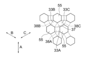
- This disclosure includes: a third land portion around which the space portion is located, the third land portion being located from the first main body surface to the second main body surface and in a third direction different from each of the first direction and the second direction in plan view; a third land portion extending to; a third main stream groove located on the first main body surface of the third land portion, the third main stream groove communicating with the space and extending in the third direction; The first land portion, the second land portion, and the third land portion intersect at the land intersection portion, At the land intersection portion, the first mainstream groove, the second mainstream groove, and the third mainstream groove communicate with each other,
- the space portion includes third space division portions located on both sides of the third land portion with respect to the third direction, A third land concave portion connecting the third space dividing portions located on both sides is located on the second main body surface of the third land portion.
- the main body sheet for a vapor chamber described in [1] may also be used.
- This disclosure includes: In the main body sheet for a vapor chamber according to the first solution described above, The space portion includes second space division portions located on both sides of the first land portion with respect to the first direction, A first land concave portion connecting the second space dividing portions located on both sides is located on the second main body surface of the first land portion.
- the main body sheet for a vapor chamber described in [13] may also be used.
- This disclosure includes: The first land portion, the second land portion, and the third land portion terminate at the land intersection portion,
- the main body sheet for a vapor chamber described in [13] or [14] may be used.
- This disclosure includes: A main body sheet for a vapor chamber in which a working fluid is sealed, a first body surface; a second body surface located on the opposite side of the first body surface; a space penetrating from the first body surface to the second body surface; a first land portion around which the space portion is located, the first land portion extending from the first body surface to the second body surface and extending in a first direction in plan view; a first mainstream groove located on the first main body surface of the first land portion, the first mainstream groove communicating with the space and extending in the first direction; a plurality of second land portions around which the space portion is located, the plurality of second land portions extending from the first body surface to the second body surface and extending in a second direction different from the first direction in plan view; 2 land section and a second mainstream groove located on the first main body surface of the second land portion, the second mainstream groove communicating with the space and extending in the second direction; a plurality of land intersection portions where each of the first land portions and each of the second land portions intersect;
- This disclosure includes: the second direction is perpendicular to the first direction,
- the main body sheet for a vapor chamber described in [16] may also be used.
- This disclosure includes: a plurality of the land intersections are located in an evaporation region where the liquid of the working fluid evaporates;
- the main body sheet for a vapor chamber described in [16] or [17] may be used.
- This disclosure includes: a plurality of the land intersections are located in a condensation region where the vapor of the working fluid condenses;
- the main body sheet for a vapor chamber according to any one of [16] to [18] may be used.
- This disclosure includes: A main body sheet for a vapor chamber in which a working fluid is sealed, a first body surface; a second body surface located on the opposite side of the first body surface; a space penetrating from the first body surface to the second body surface; a first land portion around which the space portion is located, the first land portion extending from the first body surface to the second body surface and extending in a first direction in plan view; a plurality of first mainstream grooves located on the first main body surface of the first land portion, the plurality of first mainstream grooves communicating with the space and extending in the first direction; a second land portion around which the space portion is located, the second land portion extending from the first body surface to the second body surface and extending in a second direction different from the first direction in plan view; , a plurality of second main stream grooves located on the first main body surface of the second land portion, the plurality of second main stream grooves communicating with the space and extending in the second direction; a land intersection portion where the first land portion and the second land, the
- the groove connection portion includes a plurality of first intersection grooves extending on an extension of the corresponding first mainstream groove, and a plurality of second intersection grooves extending on an extension of the corresponding second mainstream groove, Each of the first intersection grooves and each of the second intersection grooves intersect,
- the main body sheet for a vapor chamber described in [20] may also be used.
- the groove connection portion includes an intersection recess located on the first main body surface and connected to each of the first mainstream grooves and connected to each of the second mainstream grooves.
- the main body sheet for a vapor chamber described in [20] may also be used.
- This disclosure includes: A plurality of intersection protrusions that are arranged in the first direction and in the second direction and that protrude toward the first body surface are located on the bottom surface of the intersection recess;
- the main body sheet for a vapor chamber described in [22] may also be used.
- This disclosure includes: the intersection protrusion is spaced inward from the extended surface of the first body surface;
- the main body sheet for a vapor chamber described in [23] may also be used.
- the groove connection portion includes a plurality of first intersection grooves extending in the first direction and a plurality of second intersection grooves extending in the second direction,
- the width of the first intersection groove is larger than the width of the first mainstream groove
- the width of the second intersection groove is larger than the width of the second main stream groove.
- the main body sheet for a vapor chamber described in [20] may also be used.
- This disclosure includes: The number of the first intersection grooves is smaller than the number of first mainstream grooves located in the first land portion, The number of the second intersection grooves is smaller than the number of second mainstream grooves located in the second land portion.
- the main body sheet for a vapor chamber described in [25] may also be used.
- the groove connecting portion includes a first dividing groove located on one side in the first direction and a second dividing groove located on the other side in the first direction, and is an extension of the first dividing groove.
- a fourth dividing groove located on an extension of the The first dividing groove and the third dividing groove are connected at a groove intersection, The second dividing groove is not connected to the groove intersection part,
- the main body sheet for a vapor chamber described in [20] may also be used.
- This disclosure includes: The fourth dividing groove is not connected to the groove intersection part, The main body sheet for a vapor chamber described in [27] may also be used.
- This disclosure includes: A plurality of edge communication grooves and a plurality of intermediate communication grooves are located on the first main body surface of the first land portion,
- the edge side communication groove connects the space and the first mainstream groove adjacent to the space,
- the edge communication groove extends in the second direction and is aligned in the first direction
- the intermediate communication groove connects the two first mainstream grooves that are adjacent to each other,
- the intermediate communication groove extends in the second direction and is aligned in the first direction,
- the interval between the two edge side communication grooves adjacent to each other is smaller than the interval between the two intermediate communication grooves adjacent to each other,
- the main body sheet for a vapor chamber described in [20] may also be used.
- This disclosure includes: A plurality of first communication grooves are located on the first main body surface of the first land portion, the first communication groove extends in the second direction beyond the first mainstream groove;
- the main body sheet for a vapor chamber described in [20] or [21] may be used.
- This disclosure includes: A main body sheet for a vapor chamber in which a working fluid is sealed, a first body surface; a second body surface located on the opposite side of the first body surface; a space penetrating from the first body surface to the second body surface; a first land portion around which the space portion is located, the first land portion extending from the first body surface to the second body surface and extending in a first direction in plan view; a land connection area connected to the first land portion, The land connection area is a plurality of first intersection land portions extending from the first body surface to the second body surface and extending in the first direction in plan view; a plurality of first mainstream grooves located on the first main body surface of the first intersection land portion, the plurality of first mainstream grooves communicating with the space portion and extending in the first direction; a plurality of second intersection lands extending from the first body surface to the second body surface and extending in a second direction different from the first direction in plan view; a plurality of second main flow grooves located on the first main body surface
- This disclosure includes: The width of the first intersection land portion is different from the width of the first land portion,
- the main body sheet for a vapor chamber described in [31] may also be used.
- the space portion includes a first space division portion located on both sides of the second intersection land portion with respect to the second direction, A second land concave portion connecting the first space dividing portions located on both sides is located on the second main body surface of the second intersection land portion;
- the main body sheet for a vapor chamber described in [31] or [32] may be used.
- This disclosure includes: The dimension in the second direction of the first space division part located within the land connection area is smaller than the dimension in the second direction of the first space division part located outside the land connection area.
- the main body sheet for a vapor chamber described in [31] or [32] may be used.
- This disclosure includes: In the land connection region, a first through hole communicating with the second land recess is provided, The first through hole is located at a different position from the first space dividing part in plan view.
- the main body sheet for a vapor chamber according to any one of [31] to [34] may also be used.
- a land intersection space constituting the space portion is formed on the opposite side of the first body surface of the land intersection portion, The land intersection space communicates with the second land recess, The first through hole is formed at the land intersection portion and communicates with the land intersection space.
- the main body sheet for a vapor chamber according to any one of [31] to [35] may also be used.
- This disclosure includes: The first through hole is formed in the second intersection land portion, The main body sheet for a vapor chamber according to any one of [31] to [36] may also be used.
- This disclosure includes: A closing portion is provided between the two adjacent first intersection land portions and between the two adjacent second intersection land portions, A closed space constituting the space portion is located on the opposite side of the first main body surface of the closed portion.
- the main body sheet for a vapor chamber according to any one of [31] to [37] may be used.
- This disclosure includes: In a part of the peripheral edge of the land connection area, a column extending to the second main body surface is located between two adjacent land intersection parts.
- the main body sheet for a vapor chamber according to any one of [31] to [38] may also be used.
- the space portion includes second space division portions located on both sides of the first intersection land portion with respect to the first direction, A second land concave portion connecting the second space dividing portions located on both sides is located on the second main body surface of the first intersection land portion, The depth of the first land recess is different from the depth of the second land recess.
- the main body sheet for a vapor chamber according to any one of [31] to [39] may also be used.
- This disclosure includes: The land intersection portion extends from the first body surface toward the second body surface, A liquid storage portion is provided on the second body surface of the land intersection portion.
- the main body sheet for a vapor chamber according to any one of [31] to [40] may also be used.
- This disclosure includes: A main body sheet for a vapor chamber in which a working fluid is sealed, a first body surface; a second body surface located on the opposite side of the first body surface; a space penetrating from the first body surface to the second body surface; a first land portion around which the space portion is located, the first land portion extending from the first body surface to the second body surface and extending in a first direction in plan view; a plurality of first mainstream grooves located on the first main body surface of the first land portion, the plurality of first mainstream grooves communicating with the space and extending in the first direction; a land connection body located on the first body surface and connected to the first land portion; a land connection space forming the space portion and located on the opposite side of the first main body surface of the land connection body; a plurality of second through holes passing through the land connection body, the plurality of second through holes communicating with the first mainstream groove and communicating with the land connection space; a column extending from the land connection body to the second main body surface; It may also be a
- This disclosure includes: A main body sheet for a vapor chamber in which a working fluid is sealed, a first body surface; a second body surface located on the opposite side of the first body surface; a space penetrating from the first body surface to the second body surface; a first land portion around which the space portion is located, the first land portion extending from the first body surface to the second body surface and extending in a first direction in plan view; a plurality of first mainstream grooves located on the first main body surface of the first land portion, the plurality of first mainstream grooves communicating with the space and extending in the first direction; a land connection body located on the first body surface and connected to the first land portion; a land connection space forming the space portion and located on the opposite side of the first main body surface of the land connection body; a plurality of second through holes passing through the land connection body, the plurality of second through holes communicating with the first mainstream groove and communicating with the land connection space;
- the land connection body includes a first hole area including a plurality of second through holes formed with a
- the first unit circumference is a total value per unit area of the circumferences of the second through holes located in the first hole region
- the second unit circumference is a total value per unit area of the circumference of the second through hole located in the second hole region
- the second unit circumference is larger than the first unit circumference, It may also be a main body sheet for a vapor chamber.
- This disclosure includes: the second hole region is located inside the first hole region;
- the main body sheet for a vapor chamber described in [43] may also be used.
- This disclosure includes: further comprising a column extending from the land connection body to the second main body surface;
- the main body sheet for a vapor chamber described in [43] or [44] may be used.
- This disclosure includes: A groove connection portion connected to the first main flow groove and the second main flow groove and communicating with the second through hole is located on the first main body surface of the land connection body.
- the main body sheet for a vapor chamber according to any one of [43] to [45] may be used.
- This disclosure includes: A main body sheet for a vapor chamber in which a working fluid is sealed, a first body surface; a second body surface located on the opposite side of the first body surface; a space penetrating from the first body surface to the second body surface; a first land portion around which the space portion is located, the first land portion extending from the first body surface to the second body surface and extending in a first direction in plan view; a plurality of first mainstream grooves located on the first main body surface of the first land portion, the plurality of first mainstream grooves communicating with the space and extending in the first direction; a land connection body located on the first body surface and connected to the first land portion; a land connection space forming the space portion and located on the opposite side of the first main body surface of the land connection body; a plurality of second through holes passing through the land connection body, the plurality of second through holes communicating with the first mainstream groove and communicating with the land connection space;
- the land connection body includes a first hole region including a plurality of second through holes formed with a
- the first unit longitudinal dimension is the total value per unit area of the longitudinal dimensions of the second through hole located in the first hole region
- the second unit longitudinal dimension is the total value per unit area of the longitudinal dimensions of the second through hole located in the second hole region, the second unit longitudinal dimension is larger than the first unit longitudinal dimension; It may also be a main body sheet for a vapor chamber.
- This disclosure includes: A main body sheet for a vapor chamber in which a working fluid is sealed, a first body surface; a second body surface located on the opposite side of the first body surface; a space penetrating from the first body surface to the second body surface; a first land portion around which the space portion is located, the first land portion extending from the first body surface to the second body surface and extending in a first direction in plan view; a plurality of first mainstream grooves located on the first main body surface of the first land portion, the plurality of first mainstream grooves communicating with the space and extending in the first direction; a land connection body located on the first body surface and connected to the first land portion; a land connection space forming the space portion and located on the opposite side of the first main body surface of the land connection body; a plurality of second through holes passing through the land connection body, the plurality of second through holes communicating with the first mainstream groove and communicating with the land connection space;
- the land connection body includes a first hole area including a plurality of second through holes formed at a
- This disclosure includes: A main body sheet for a vapor chamber in which a working fluid is sealed, a first body surface; a second body surface located on the opposite side of the first body surface; a space penetrating from the first body surface to the second body surface; a first land portion around which the space portion is located, the first land portion extending from the first body surface to the second body surface and extending in a first direction in plan view; a plurality of first mainstream grooves located on the first main body surface of the first land portion, the plurality of first mainstream grooves communicating with the space and extending in the first direction; a land connection body located on the first body surface and connected to the first land portion; a land connection space forming the space portion and located on the opposite side of the first main body surface of the land connection body; a plurality of second through holes penetrating the land connection body, the plurality of second through holes communicating with the first mainstream groove and the second mainstream groove and communicating with the land connection space;
- the land connection body includes a first hole region including a plurality of
- the first unit number is the number per unit area of the second through holes located in the first hole region
- the second unit number is the number of second through holes located in the second hole region per unit area
- the second number of units is greater than the first number of units, It may also be a main body sheet for a vapor chamber.
- This disclosure includes: A main body sheet for a vapor chamber in which a working fluid is sealed, a first body surface; a second body surface located on the opposite side of the first body surface; a space penetrating from the first body surface to the second body surface; a first land portion around which the space portion is located, the first land portion extending from the first body surface to the second body surface and extending in a first direction in plan view; a plurality of first mainstream grooves located on the first main body surface of the first land portion, the plurality of first mainstream grooves communicating with the space and extending in the first direction; a plurality of second land portions around which the space portion is located, the plurality of second land portions extending from the first body surface to the second body surface and extending in a second direction different from the first direction in plan view; 2 land section and a plurality of second main stream grooves located on the first main body surface of the second land portion, the plurality of second main stream grooves communicating with the space and extending in the second direction; a land connection area connected
- the groove cross-sectional area is larger than the total value of the flow path cross-sectional areas of the intersection grooves at each of the third connection positions, It may also be a main body sheet for a
- This disclosure includes: A main body sheet for a vapor chamber in which a working fluid is sealed, a first body surface; a second body surface located on the opposite side of the first body surface; a space penetrating from the first body surface to the second body surface; a first land portion around which the space portion is located, the first land portion extending from the first body surface to the second body surface and extending in a first direction in plan view; a plurality of first mainstream grooves located on the first main body surface of the first land portion, the plurality of first mainstream grooves communicating with the space and extending in the first direction; a land connection body located on the first body surface and connected to the first land portion; a land connection space forming the space portion and located on the opposite side of the first main body surface of the land connection body; a plurality of second through holes passing through the land connection body, the plurality of second through holes communicating with the first mainstream groove and communicating with the land connection space; a plurality of intersection grooves located on the first main body surface of the land connection body, the plurality of
- This disclosure includes: A main body sheet for a vapor chamber in which a working fluid is sealed, a first body surface; a second body surface located on the opposite side of the first body surface; a space penetrating from the first body surface to the second body surface; a first land portion around which the space portion is located, the first land portion extending from the first body surface to the second body surface and extending in a first direction in plan view; a plurality of first mainstream grooves located on the first main body surface of the first land portion, the plurality of first mainstream grooves communicating with the space and extending in the first direction; a land connection body connected to the first land portion located on the first body surface; and a land connection space forming the space portion located on the opposite side of the land connection body from the first body surface.
- the total value of the planar area of the second through hole is 3% to 30% of the planar area of the land connection body, It may also be a main body sheet for a vapor chamber.
- This disclosure includes: A main body sheet for a vapor chamber in which a working fluid is sealed, a first body surface; a second body surface located on the opposite side of the first body surface; a space penetrating from the first body surface to the second body surface; a first land portion around which the space portion is located, the first land portion extending from the first body surface to the second body surface and extending in a first direction in plan view; a plurality of first mainstream grooves located on the first main body surface of the first land portion, the plurality of first mainstream grooves communicating with the space and extending in the first direction; a land connection body located on the first body surface and connected to the first land portion; a land connection space forming the space portion and located on the opposite side of the first main body surface of the land connection body; a plurality of second through holes passing through the land connection body, the plurality of second through holes communicating with the first mainstream groove and communicating with the land connection space; a plurality of intersection grooves located on the first main body surface of the land connection body, the plurality of
- This disclosure includes: The first sheet, a second sheet; a main body sheet for a vapor chamber according to any one of [1] to [51], located between the first sheet and the second sheet; It may also be a vapor chamber.
- This disclosure includes: housing and an electronic device housed within the housing; and the vapor chamber according to [54], which is in thermal contact with the electronic device. It may be an electronic device.
- This disclosure includes: A main body sheet for a vapor chamber in which a working fluid is sealed, a first body surface; a second body surface located on the opposite side of the first body surface; a space located on the first body surface; a first land portion around which the space portion is located, the first land portion including the first main body surface and extending in a first direction in a plan view; a first groove flow path portion located on the first body surface of the first land portion, the first groove flow path portion including a first mainstream groove communicating with the space portion and extending in the first direction; , a storage flow path portion located on the first main body surface and connected to the first main stream groove; A channel cross-sectional area of the storage channel section perpendicular to the first direction is larger than a channel cross-sectional area of the first groove channel section orthogonal to the first direction. It may also be a main body sheet for a vapor chamber.
- the storage channel portion includes a storage main groove,
- the storage main groove has a width larger than the width of the first main flow groove or a depth greater than the depth of the first main flow groove.
- the main body sheet for a vapor chamber described in [56] may also be used.
- This disclosure includes: A plurality of the first mainstream grooves are located on the first main body surface of the first land portion,
- the storage channel portion includes a storage recess located on the first main body surface and connected to each of the first mainstream grooves.
- the main body sheet for a vapor chamber described in [56] may also be used.
- a protrusion protruding toward the first body surface is located on the bottom surface of the storage recess.
- the main body sheet for a vapor chamber described in [58] may also be used.
- the storage recess includes an outer edge that is curved in plan view.
- the main body sheet for a vapor chamber according to [58] or [59] may also be used.
- This disclosure includes: the first mainstream groove protrudes into the storage recess in plan view;
- the main body sheet for a vapor chamber according to any one of [58] to [60] may also be used.
- a second partition wall that partitions the storage recess with respect to the space is located on the first main body surface.
- the main body sheet for a vapor chamber according to any one of [58] to [61] may also be used.
- This disclosure includes: A partition wall groove connecting the space and the storage recess is located in the second partition wall,
- the main body sheet for a vapor chamber described in [62] may also be used.
- the first land portion includes a land body portion and a land wide portion having a width larger than the width of the land body portion,
- the storage channel portion is located on the first main body surface of the land wide portion.
- the main body sheet for a vapor chamber described in [62] or [63] may be used.
- the first land portion extends from the first body surface to the second body surface
- the storage channel section includes a through space penetrating from the first body surface to the second body surface
- a second partition wall that partitions the through space with respect to the space portion is located on the first main body surface.
- the main body sheet for a vapor chamber described in [56] may also be used.
- the storage flow path portion is in contact with the first groove flow path portion on one side in the first direction, and is in contact with a first partition wall on the other side in the first direction,
- the first partition wall extends across the entire width of the storage flow path in a direction perpendicular to the first direction.
- the main body sheet for a vapor chamber according to any one of [56] to [65] may be used.
- This disclosure provides: comprising a frame portion that defines the space portion, one end of the first land in the first direction is connected to the frame, The first partition wall is located in the frame part,
- the main body sheet for a vapor chamber described in [66] may also be used.
- This disclosure includes: The storage flow path portion is in contact with the first groove flow path portion on both sides in the first direction.
- the main body sheet for a vapor chamber according to any one of [56] to [65] may be used.
- This disclosure includes: a second land portion around which the space portion is located, the second land portion including the first main body surface and extending in a second direction different from the first direction in plan view; a second groove flow path portion located on the first body surface of the second land portion, the second groove flow path portion including a second main flow groove communicating with the space portion and extending in the second direction; , a land intersection portion where the first land portion and the second land portion intersect, The storage channel portion is located on the first body surface of the land intersection portion, The first mainstream groove is connected to the storage flow path portion, and the second mainstream groove is connected to the storage flow path portion.
- the main body sheet for a vapor chamber according to any one of [56] to [65] may be used.
- This disclosure includes: A channel cross-sectional area of the storage channel section perpendicular to the second direction is larger than a channel cross-sectional area of the second groove channel section orthogonal to the second direction.
- the main body sheet for a vapor chamber described in [69] may also be used.
- This disclosure includes: A main body sheet for a vapor chamber in which a working fluid is sealed, a first body surface; a second body surface located on the opposite side of the first body surface; a space located on the first body surface; a first land portion around which the space portion is located, the first land portion including the first main body surface and extending in a first direction in a plan view; a first main flow groove located on the first main body surface of the first land portion, the first main flow groove including a plurality of first main flow grooves communicating with the space and extending in the first direction; , a storage flow path portion located on the first main body surface and connected to the first main flow groove, the storage flow path portion being in contact with the first groove flow path portion on one side in the first direction; a storage flow path portion that is not in contact with the space portion on the other side of the storage flow path portion,
- the first surface survival rate which indicates the ratio of the area where the first main body surface remains in the storage flow path section, is the ratio of the area where the first main body surface remains in
- the storage channel portion includes a plurality of storage main flow grooves extending on an extension of the corresponding first main flow groove, and a plurality of storage communication grooves,
- the storage communication groove intersects with the main storage groove and extends beyond the main storage groove in a direction perpendicular to the first direction.
- the main body sheet for a vapor chamber described in [71] may also be used.
- the storage channel portion includes a storage recess located on the first main body surface and connected to each of the first mainstream grooves.
- the main body sheet for a vapor chamber described in [71] may also be used.
- a protrusion protruding toward the first body surface is located on the bottom surface of the storage recess.
- the main body sheet for a vapor chamber described in [72] may also be used.
- This disclosure includes: A second partition wall that partitions the storage recess with respect to the space is located on the first main body surface.
- the main body sheet for a vapor chamber described in [73] or [74] may be used.
- the first land portion includes a land body portion and a land wide portion having a width larger than the width of the land body portion,
- the storage channel portion is located on the first main body surface of the land wide portion.
- the main body sheet for a vapor chamber described in [75] may also be used.
- the storage flow path portion is in contact with a first partition wall on a side opposite to the first groove flow path portion,
- the first partition wall extends across the entire width of the storage flow path in a direction perpendicular to the first direction.
- the main body sheet for a vapor chamber according to any one of [71] to [76] may also be used.
- the storage flow path portion is in contact with the first groove flow path portion on both sides in the first direction.
- the main body sheet for a vapor chamber according to any one of [71] to [76] may also be used.
- This disclosure includes: a second land portion around which the space portion is located, the second land portion including the first main body surface and extending in a second direction different from the first direction in plan view; a second main flow groove located on the first main body surface of the second land portion, the second main flow groove communicating with the space and extending in the second direction; a land intersection portion where the first land portion and the second land portion intersect, The storage channel portion is located on the first body surface of the land intersection portion, The first mainstream groove is connected to the storage flow path portion, and the second mainstream groove is connected to the storage flow path portion.
- the main body sheet for a vapor chamber according to any one of [71] to [74] may be used.
- the first surface survival rate which indicates the ratio of the area where the first main body surface remains in the storage flow path section, is the ratio of the area where the first main body surface remains in the second groove flow path section. smaller than the second surface survival rate shown.
- the main body sheet for a vapor chamber described in [79] may also be used.
- This disclosure includes: A main body sheet for a vapor chamber in which a working fluid is sealed, a first body surface; a second body surface located on the opposite side of the first body surface; a space located on the first body surface; a first land portion around which the space portion is located, the first land portion including the first main body surface and extending in a first direction in a plan view; a first mainstream groove located on the first main body surface of the first land portion, the first groove channel portion including a first mainstream groove that communicates with the space and extends in the first direction; a storage flow path portion located on the first main body surface and connected to the first main stream groove;
- the first surface survival rate which indicates the ratio of the area where the first main body surface remains in the storage flow path section, is the ratio of the area where the first main body surface remains in the first groove flow path section.
- the storage channel portion includes a storage recess located on the first main body surface and connected to the first mainstream groove, A second partition wall that partitions the storage recess with respect to the space is located on the first main body surface. It may also be a main body sheet for a vapor chamber.
- the first land portion includes a land body portion and a land wide portion having a width larger than the width of the land body portion,
- the storage channel portion is located on the first main body surface of the land wide portion.
- the main body sheet for a vapor chamber described in [81] may also be used.
- This disclosure provides: The first sheet, a second sheet; a main body sheet for a vapor chamber according to any one of [56] to [82], located between the first sheet and the second sheet; It may also be a vapor chamber.
- This disclosure includes: A vapor chamber in which a working fluid is enclosed, A main body sheet for a vapor chamber, including a first main body surface and a second main body surface located on the opposite side of the first main body surface; a first sheet located on the first body surface; comprising a storage flow path section;
- the main body sheet is a space located on the first body surface; a first land portion around which the space portion is located, the first land portion including the first main body surface and extending in a first direction in a plan view; a first groove flow path portion located on the first body surface of the first land portion, the first groove flow path portion including a first mainstream groove communicating with the space portion and extending in the first direction; , including;
- the storage channel portion is located on a surface of the first sheet on the side of the main sheet, The storage channel portion is connected to the first mainstream groove and overlaps the first mainstream groove in plan view, A channel cross-sectional area of the storage channel section perpendicular to the first direction is larger than a channel cross-sectional area of
- a vapor chamber in which a working fluid is enclosed A main body sheet for a vapor chamber, including a first main body surface and a second main body surface located on the opposite side of the first main body surface; a first sheet located on the first body surface; a second sheet located on the second main body surface; comprising a storage flow path section;
- the main body sheet is a space penetrating from the first body surface to the second body surface; a first land portion around which the space portion is located, the first land portion extending from the first body surface to the second body surface and extending in a first direction in plan view; a first groove flow path portion located on the first body surface of the first land portion, the first groove flow path portion including a first mainstream groove communicating with the space portion and extending in the first direction; , including;
- the two main body sheets are located between the first sheet and the second sheet,
- the two main body sheets are constituted by a first main body sheet and a second main body sheet that are laminated together, the first sheet is located on the first main body
- This disclosure provides: housing and an electronic device housed within the housing; the vapor chamber according to any one of [83] to [85] in thermal contact with the electronic device; It may be an electronic device.
- heat dissipation performance can be improved.
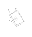
- FIG. 1 is a schematic perspective view illustrating an electronic device according to a first embodiment of the present disclosure.
- FIG. 2 is a plan view showing the vapor chamber shown in FIG. 1.
- FIG. 3 is a cross-sectional view taken along line AA in FIG. 2.
- FIG. 4 is a plan view showing the inner surface of the first sheet shown in FIG. 3.
- FIG. 5 is a plan view showing the inner surface of the second sheet shown in FIG. 3.
- FIG. 6 is a plan view showing the first main body surface of the wick sheet shown in FIG. 3.
- FIG. 7 is a plan view showing the second main body surface of the wick sheet shown in FIG. 3.
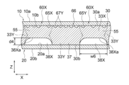
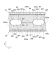
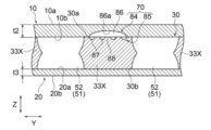
- FIG. 8 is a partially enlarged sectional view of FIG. 3.
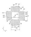
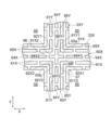
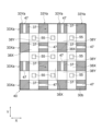
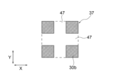
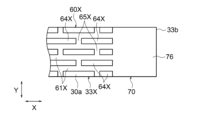
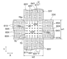
- FIG. 9 is a plan view of the land intersection shown in FIG. 6.
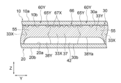
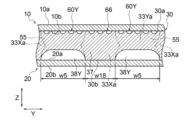
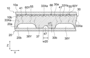
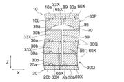
- FIG. 10 is a cross-sectional view showing the second land recess along line BB in FIG. 9.
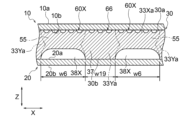
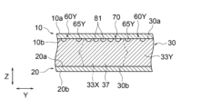
- FIG. 11 is a cross-sectional view showing the first land recess along line CC in FIG. 9.
- FIG. 12 is a partially enlarged plan view of the liquid flow path section shown in FIG. 6.
- FIG. 13 is a plan view of the land intersection shown in FIG. 6.
- FIG. 14 is a sectional view showing a modification of the second land recess shown in FIG. 10.
- FIG. 15 is a sectional view showing a modification of the first land recess shown in FIG. 11.
- FIG. 16 is a sectional view showing another modification of the second land recess shown in FIG. 10.
- FIG. 17 is a plan view showing a modification of the groove connecting portion shown in FIG. 13.
- FIG. 13 is a plan view showing a modification of the groove connecting portion shown in FIG. 13.
- FIG. 18 is a sectional view showing the groove connection portion shown in FIG. 17.
- FIG. 19 is a plan view showing another modification of the groove connecting portion shown in FIG. 13.
- FIG. 20 is a sectional view showing the groove connection portion shown in FIG. 19.
- FIG. 21 is a plan view showing another modification of the groove connection portion shown in FIG. 13.
- FIG. 22 is a plan view showing another modification of the groove connecting portion shown in FIG. 13.
- FIG. 23 is a plan view showing another modification of the groove connection portion shown in FIG. 13.
- FIG. 24 is a plan view showing another modification of the groove connecting portion shown in FIG. 13.
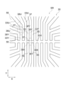
- FIG. 25 is a plan view showing a modification of the land portion shown in FIG. 6.
- FIG. FIG. 26 is a partially enlarged plan view of FIG. 25.
- FIG. 27 is a schematic plan view showing the liquid flow path section shown in FIG. 26.
- FIG. 28 is a plan view showing another modification of the land portion shown in FIG. 6.
- FIG. 29 is a plan view showing another modification of the land portion shown in FIG. 6.
- FIG. 30 is a schematic plan view showing the liquid flow path section shown in FIG. 29.
- FIG. 31 is a plan view showing another modification of the land portion shown in FIG. 6.
- FIG. 32 is a plan view showing another modification of the land portion shown in FIG. 6.
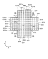
- 33 is a plan view showing a land connection area including the land intersection shown in FIG. 9.
- FIG. 34 is a cross-sectional view showing the second land recess along line DD in FIG. 33.
- FIG. 35 is a cross-sectional view showing the first land recess along the line EE in FIG. 33.
- FIG. 36 is a plan view showing a modification of the land connection area shown in FIG. 33.
- FIG. 37 is a plan view showing a modification of the passage dividing portion shown in FIG. 36.
- FIG. 38 is a plan view showing another modification of the land connection area shown in FIG. 33.
- FIG. 39 is a cross-sectional view showing the space dividing portion along line FF in FIG. 38.
- FIG. 40A is a plan view showing another modification of the land connection area shown in FIG. 33.
- FIG. 40B is a plan view showing a modification of the planar shape of the passage dividing portion shown in FIG. 33.
- FIG. 41A is a sectional view showing a modification of the land intersection shown in FIG. 35.
- FIG. FIG. 41B is a sectional view showing another modification of the land intersection shown in FIG. 35.
- FIG. 42 is a plan view showing another modification of the land connection area shown in FIG. 33.
- FIG. 43 is a cross-sectional view showing the first through hole along line GG in FIG. 42.
- FIG. 44 is a partially enlarged plan view showing another modification of the land connection area shown in FIG. 33.
- FIG. 45 is a cross-sectional view showing the first through hole along line HH in FIG. 44.
- FIG. 46 is a plan view showing another modification of the land connection area shown in FIG. 33.
- FIG. 47 is a cross-sectional view of the column section taken along line II in FIG. 46.
- FIG. 48 is a plan view showing another modification of the land connection area shown in FIG. 33.
- FIG. 49 is a cross-sectional view of the column section taken along line JJ in FIG. 48.
- FIG. 50 is a sectional view showing another modification of the land recess shown in FIG. 35.
- FIG. 51 is a sectional view showing another modification of the land recess shown in FIG. 35.
- FIG. 52 is a plan view showing another modification of the wick sheet shown in FIG. 6.
- FIG. 53 is a plan view showing another modification of the wick sheet shown in FIG. 6.
- FIG. 54 is a plan view showing another modification of the wick sheet shown in FIG. 6.
- FIG. 55 is a sectional view showing another modification of the land intersection shown in FIG. 35.
- FIG. 56 is a sectional view showing another modification of the land intersection shown in FIG. 35.
- FIG. 57 is a plan view showing another modification of the land connection area shown in FIG. 33.
- FIG. 58 is a cross-sectional view showing the land connection area along line KK in FIG. 57.
- FIG. 59 is a partially enlarged plan view showing a modification of the liquid storage groove shown in FIG. 57.
- FIG. 60 is a sectional view showing another modification of the land intersection shown in FIG. 58.
- FIG. 61 is a sectional view showing another modification of the land intersection shown in FIG. 58.
- FIG. 62 is a plan view showing another modification of the land connection area shown in FIG. 33.
- FIG. 63A is a cross-sectional view showing the land connection area along line LL in FIG. 62.
- FIG. 63B is a partially enlarged sectional view of the second through hole shown in FIG. 62.
- FIG. 64 is a partially enlarged plan view showing the land connection area shown in FIG. 62.
- FIG. 65 is a plan view showing a modification of the land connection area shown in FIG. 62.
- FIG. 66 is a plan view showing another modification of the land connection area shown in FIG. 62.
- FIG. 67 is a plan view showing another modification of the land connection area shown in FIG. 62.
- FIG. 68A is a plan view showing an example of the second through hole shown in FIG. 62.
- FIG. 68B is a plan view showing an example of the second through hole shown in FIG. 62.
- FIG. 68C is a plan view showing an example of the second through hole shown in FIG. 62.
- FIG. 69 is a plan view showing another modification of the land connection area shown in FIG. 62.
- FIG. 70A is a plan view showing the land connection area shown in FIG. 62.
- FIG. 70B is a plan view showing the second through hole of FIG. 70A.
- FIG. 70C is a schematic plan view showing the relationship between the second through hole and the intersection groove shown in FIG. 70A.
- FIG. 71 is a diagram for explaining a contact area of an electronic device.
- FIG. 72 is a plan view showing a vapor chamber according to a second embodiment of the present disclosure.
- FIG. 73 is a plan view showing the first main body surface of the wick sheet of the vapor chamber shown in FIG. 72.
- FIG. 74 is a plan view showing the second main body surface of the wick sheet of the vapor chamber shown in FIG. 72.
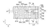
- FIG. 75 is a partially enlarged plan view of the storage channel section shown in FIG. 73.
- FIG. 76 is a cross-sectional view showing the storage channel section along line MM in FIG. 75.
- FIG. 77 is a cross-sectional view showing the storage channel section along line NN in FIG. 75.
- FIG. 78 is a partially enlarged plan view showing a modification of the storage channel section shown in FIG. 75.
- FIG. 79 is a partially enlarged plan view showing another modification of the storage channel section shown in FIG. 75.
- FIG. 80 is a partially enlarged plan view showing another modification of the storage channel section shown in FIG. 75.
- FIG. 81 is a cross-sectional view showing the storage channel section along the line OO in FIG. 80.
- FIG. 82 is a partially enlarged plan view showing another modification of the storage channel section shown in FIG. 75.
- FIG. 83 is a partially enlarged plan view showing another modification of the storage channel section shown in FIG. 75.
- FIG. 84 is a cross-sectional view showing the storage channel section along line PP in FIG. 83.
- FIG. 85 is a partially enlarged plan view showing another modification of the storage channel section shown in FIG. 75.
- FIG. 86 is a partially enlarged plan view showing another modification of the storage channel section shown in FIG. 75.
- FIG. 87 is a cross-sectional view showing the storage channel section along the line QQ in FIG. 86.
- FIG. 88 is a partially enlarged plan view showing another modification of the storage channel section shown in FIG. 75.
- FIG. 89 is a cross-sectional view showing the storage flow path section taken along line RR in FIG. 88.
- FIG. 90 is a partially enlarged plan view showing another modification of the storage channel section shown in FIG. 75.
- FIG. 91 is a partially enlarged plan view showing another modification of the storage channel section shown in FIG. 75.
- FIG. 92 is a partially enlarged plan view showing another modification of the storage channel section shown in FIG. 75.
- FIG. 93 is a partially enlarged plan view showing another modification of the storage channel section shown in FIG. 75.
- FIG. 94 is a cross-sectional view showing the storage channel section along line SS in FIG. 93.
- FIG. 95 is a sectional view showing a modification of the storage channel section shown in FIG. 94.
- FIG. 96 is a sectional view showing another modification of the storage channel section shown in FIG. 94.
- FIG. 97 is a sectional view showing another modification of the storage channel section shown in FIG. 94.
- FIG. 98 is a partially enlarged plan view showing another modification of the storage channel section shown in FIG. 75.
- FIG. 99 is a partially enlarged plan view showing another modification of the storage channel section shown in FIG. 75.
- FIG. 100 is a partially enlarged plan view showing another modification of the storage channel section shown in FIG. 75.
- FIG. 101 is a cross-sectional view showing the storage channel section along the line TT in FIG. 100.
- FIG. 102 is a sectional view showing another modification of the storage channel section shown in FIG. 76.
- FIG. 103 is a sectional view showing another modification of the storage channel section shown in FIG. 76.
- FIG. 104 is a sectional view showing another modification of the storage channel section shown in FIG. 76.
- FIG. 105 is a partially enlarged plan view showing another modification of the storage channel section shown in FIG. 75.
- FIG. 106 is a sectional view showing the storage flow path section shown in FIG. 105, and is a sectional view along the X direction.
- FIG. 107 is a sectional view showing the storage channel section shown in FIG.
- FIG. 108 is a sectional view showing a modified example of the storage flow path section shown in FIG. 106, and is a sectional view along the X direction.
- FIG. 109 is a cross-sectional view showing the storage channel section shown in FIG. 108, and is a cross-sectional view along the Y direction.
- FIG. 110 is a sectional view showing another modification of the storage flow path section shown in FIG. 106, and is a sectional view along the X direction.
- FIG. 111 is a cross-sectional view showing the storage channel section shown in FIG. 110, and is a cross-sectional view along the Y direction.
- FIG. 112 is a sectional view showing another modification of the storage flow path section shown in FIG. 106, and is a sectional view along the X direction.
- FIG. 113 is a cross-sectional view showing the storage channel section shown in FIG. 112, and is a cross-sectional view along the Y direction.
- FIG. 114 is a plan view showing the first main body surface of the wick sheet according to the third embodiment of the present disclosure.
- FIG. 115 is a partially enlarged plan view of the storage channel section shown in FIG. 114.
- FIG. 116 is a cross-sectional view showing the storage channel section along the line U--U in FIG. 115.
- FIG. 117 is a partially enlarged plan view showing a modification of the storage flow path section shown in FIG. 115.
- FIG. 118 is a cross-sectional view showing the storage channel section along line VV in FIG. 117.
- FIG. 119 is a partially enlarged plan view showing another modification of the storage channel section shown in FIG
- geometric conditions, physical properties, terms specifying the degree of geometric conditions or physical properties, numerical values indicating geometric conditions or physical properties, etc. are strictly It may be interpreted without being bound by meaning. These geometrical conditions, physical characteristics, terms, numerical values, etc. may be interpreted to include the range to which similar functions can be expected. Examples of terms specifying geometric conditions include “length,” “angle,” “shape,” “parallel,” “orthogonal,” and “identical.” Further, in order to make the drawings clear, the shapes of a plurality of parts that can be expected to have similar functions are regularly described. However, without being bound by a strict meaning, the shapes of the portions may be different from each other as long as the function can be expected. In the drawings, boundaries indicating bonding surfaces between members are shown as simple straight lines for convenience, but they are not restricted to being strictly straight lines, and may be drawn within a range where the desired bonding performance can be expected. The shape of the boundary line is arbitrary.
- the vapor chamber 1 is housed in a housing H of an electronic device E together with an electronic device D that generates heat, and is a device for cooling the electronic device D.
- the electronic device E include mobile terminals such as portable terminals and tablet terminals.
- the electronic device D include a central processing unit (CPU), a light emitting diode (LED), a power semiconductor, and the like.
- the electronic device D may also be referred to as a cooled device.
- the electronic device E may include a housing H, an electronic device D housed in the housing H, and a vapor chamber 1.
- a touch panel display TD is provided on the front surface of the housing H.
- the vapor chamber 1 is housed within a housing H and placed in thermal contact with an electronic device D.
- the vapor chamber 1 receives heat generated by the electronic device D when the electronic equipment E is used.
- the heat received by the vapor chamber 1 is released to the outside of the vapor chamber 1 via working fluids 2a and 2b, which will be described later, and the electronic device D is effectively cooled.
- the electronic device D corresponds to a central processing unit or the like.
- the vapor chamber 1 has a sealed space 3 in which working fluids 2a and 2b (see FIG. 6) are sealed. As the working fluids 2a and 2b in the sealed space 3 undergo phase changes repeatedly, the electronic device D described above is cooled.
- the working fluids 2a, 2b contain water. Examples of the working fluids 2a and 2b include pure water and a mixture thereof.
- the vapor chamber 1 according to this embodiment is composed of three layers. More specifically, the vapor chamber 1 according to the present embodiment includes a first sheet 10, a second sheet 20, a wick sheet 30, a vapor flow path section 50, and liquid flow path sections 60X and 60Y. We are prepared.
- the second sheet 20 is located on the opposite side of the first sheet 10 with respect to the wick sheet 30.
- the wick sheet 30 is an example of a main body sheet, and is located between the first sheet 10 and the second sheet 20.
- the second sheet 20, the wick sheet 30, and the first sheet 10 are stacked in this order.
- the vapor chamber 1 shown in FIG. 2 is generally formed into a thin flat plate shape.
- the planar shape of the vapor chamber 1 is arbitrary, it may be a rectangular shape as shown in FIG.
- the planar shape of the vapor chamber 1 may be, for example, a rectangle with one side of 1 cm and the other side of 3 cm, or a square with one side of 15 cm.
- the planar dimensions of the vapor chamber 1 are arbitrary.
- the planar shape of the vapor chamber 1 is a rectangular shape whose longitudinal direction is the X direction, which will be described later.
- the first sheet 10, the second sheet 20, and the wick sheet 30 may have the same planar shape as the vapor chamber 1, as shown in FIGS. 4 to 7.
- the planar shape of the vapor chamber 1 is not limited to a rectangular shape, and may be any shape such as a circular shape, an elliptical shape, an L-shape, or a T-shape.
- the vapor chamber 1 has an evaporation region SR where the working fluid 2b evaporates, and a condensation region CR where the working vapor 2a condenses.
- the working steam 2a is a working fluid in a gaseous state
- the working fluid 2b is a working fluid in a liquid state.
- the evaporation region SR is a region that overlaps with the electronic device D in plan view and is a region that comes into contact with the electronic device D.
- the position of the evaporation region SR is arbitrary. In this embodiment, the evaporation region SR is formed at a position relatively close to one end (the left end in FIG. 2) of the vapor chamber 1 in the X direction. Heat from the electronic device D is transmitted to the evaporation region SR, and the working fluid 2b is evaporated by this heat to generate working steam 2a. Heat from the electronic device D can be transmitted not only to the region overlapping the electronic device D in a plan view but also to the periphery of the region overlapping the electronic device D. Therefore, the evaporation region SR may include a region overlapping the electronic device D and a region around the same in a plan view.
- the condensation region CR is a region that does not overlap with the electronic device D in plan view, and is a region where the working steam 2a mainly emits heat and condenses.
- the condensation region CR in this embodiment may be mainly formed at a position relatively close to the other end (the right end in FIG. 2) of the vapor chamber 1 in the X direction.
- the condensation region CR may be formed at a position to the left of the evaporation region SR, a position above the evaporation region SR, and a position below the evaporation region SR.
- the condensation region CR may be a region around the evaporation region SR. Heat from the working steam 2a is released in the condensation region CR.
- Working steam 2a is cooled and condensed to produce working fluid 2b.
- a plan view is a state in which the vapor chamber 1 is viewed from a direction perpendicular to a surface that receives heat from the electronic device D and a surface that emits the received heat.
- the surface that receives heat corresponds to the first sheet outer surface 10a of the first sheet 10, which will be described later.
- the surface that emits heat corresponds to a second sheet outer surface 20b of the second sheet 20, which will be described later.
- the first sheet 10 includes a first sheet outer surface 10a located on the opposite side to the wick sheet 30, and a first sheet inner surface 10b facing the wick sheet 30.
- the electronic device D mentioned above may come into contact with the first sheet outer surface 10a.
- a first main body surface 30a of the wick sheet 30, which will be described later, is in contact with the first sheet inner surface 10b.
- the first sheet 10 may be formed into a substantially flat shape.
- the first sheet 10 may have a substantially constant thickness.
- the second sheet 20 includes a second sheet inner surface 20a facing the wick sheet 30, and a second sheet outer surface 20b located on the opposite side to the wick sheet 30.
- the housing member Ha may be in contact with the second sheet outer surface 20b.
- the housing member Ha is a member that constitutes the housing H.
- a second main body surface 30b of the wick sheet 30, which will be described later, is in contact with the second sheet inner surface 20a.
- the second sheet 20 may be formed into a substantially flat shape.
- the second sheet 20 may have a substantially constant thickness.
- wick sheet 30 will be explained.
- an example in which one wick sheet 30 is located between the first sheet 10 and the second sheet 20 will be described.
- a plurality of wick sheets 30 may be located between the first sheet 10 and the second sheet 20.
- the wick sheet 30 includes a first main body surface 30a and a second main body surface 30b located on the opposite side of the first main body surface 30a.
- the first sheet inner surface 10b of the first sheet 10 is in contact with the first main body surface 30a.
- the second sheet inner surface 20a of the second sheet 20 is in contact with the second main body surface 30b.
- the first sheet inner surface 10b of the first sheet 10 and the first main body surface 30a of the wick sheet 30 may be diffusion bonded.
- the first sheet inner surface 10b and the first body surface 30a may be permanently joined to each other.
- the second sheet inner surface 20a of the second sheet 20 and the second main body surface 30b of the wick sheet 30 may be diffusion bonded.
- the second sheet inner surface 20a and the second body surface 30b may be permanently joined to each other.
- the term "permanently bonded” is not limited to a strict meaning, but is used to mean that the vapor chamber 1 is bonded to such an extent that the hermeticity of the sealed space 3 can be maintained during operation. ing.
- the wick sheet 30 defines a steam flow path section 50, which will be described later. More specifically, the wick sheet 30 includes a frame portion 32, at least one first land portion 33X, and at least one second land portion 33Y. As shown in FIGS. 3, 6, and 7, the wick sheet 30 may include a plurality of first land portions 33X and a plurality of second land portions 33Y.
- the frame portion 32 is formed into a rectangular frame shape along the X direction and the Y direction in plan view.
- the land portions 33X and 33Y are located inside the frame portion 32 in plan view.
- the steam flow path section 50 is located around the first land section 33X and around the second land section 33Y.
- the frame portion 32 and the land portions 33X, 33Y are portions where the material of the wick sheet 30 remains without being etched in the etching process described later.
- the frame portion 32 and the land portions 33X, 33Y include a first body surface 30a and a second body surface 30b, and extend from the first body surface 30a to the second body surface 30b.
- a first steam passage 51 (described later) through which working steam 2a flows is formed between the frame portion 32 and the adjacent first land portion 33X.
- a steam passage 52 (described later) through which working steam 2a flows is formed between the first land portions 33X adjacent to each other.
- the first land portion 33X may extend in an elongated shape with the X direction as the longitudinal direction in plan view.
- the second land portion 33Y may extend in an elongated shape with the Y direction as the longitudinal direction in plan view.
- the planar shape of the land portions 33X and 33Y may be an elongated rectangular shape.
- the first land portions 33X may be located parallel to each other.
- the second land portions 33Y may be located parallel to each other.
- the first land portion 33X and the second land portion 33Y may be spaced apart from the frame portion 32 as shown in FIGS. 6 and 7, or may be connected to the frame portion 32.
- the X direction is an example of a first direction, and corresponds to the left-right direction in FIGS. 6 and 7.
- the Y direction is an example of a second direction, and is a direction perpendicular to the X direction in plan view.
- the Y direction corresponds to the vertical direction in FIGS. 6 and 7.
- the direction perpendicular to the X direction and the Y direction is defined as the Z direction.
- the Z direction corresponds to the vertical direction in FIG. 3, and corresponds to the thickness direction.
- the first land portion 33X and the second land portion 33Y are orthogonal to each other. However, the first land portion 33X and the second land portion 33Y do not need to be perpendicular to each other, and the angle at which the first land portion 33X and the second land portion 33Y intersect is arbitrary.
- the width w1 of the first land portion 33X may be, for example, 100 ⁇ m to 1500 ⁇ m.
- the width w1 of the first land portion 33X is the Y-direction dimension of the first land portion 33X.
- the width w1 is the dimension of the first land portion 33X on the first body surface 30a and the second body surface 30b.
- the width w2 of the second land portion 33Y may be equal to the width w1 of the first land portion 33X, or may be different from the width w1.
- the width w2 (see FIG. 13) of the second land portion 33Y is the dimension of the second land portion 33Y in the X direction.
- the width w2 is the dimension of the second land portion 33Y on the first body surface 30a and the second body surface 30b.
- the frame portion 32 and each land portion 33X, 33Y may be diffusion bonded to the first sheet 10 or may be diffusion bonded to the second sheet 20. This improves the mechanical strength of the vapor chamber 1.
- the first main body surface 30a and the second main body surface 30b of the wick sheet 30 may be formed in a flat shape over the frame portion 32 and each land portion 33X, 33Y.
- the steam flow path section 50 may be provided on the first main body surface 30a of the wick sheet 30.
- the steam flow path section 50 is an example of a space section in which the working fluids 2a and 2b are sealed.
- the steam flow path portion 50 may be a flow path through which the working steam 2a mainly passes.
- the working fluid 2b may also pass through the steam flow path section 50.
- the steam flow path portion 50 may extend from the first body surface 30a to the second body surface 30b, or may penetrate the wick sheet 30.
- the steam flow path portion 50 may be covered with the first sheet 10 on the first body surface 30a, and may be covered with the second sheet 20 on the second body surface 30b.
- the second sheet 20 covers the steam flow path section 50 from the opposite side to the first sheet 10.
- the steam passage section 50 may include a first steam passage 51 and a plurality of second steam passages 52.
- the first steam passage 51 is formed between the frame portion 32 and the first land portion 33X that are adjacent to each other.
- the planar shape of the first steam passage 51 may be a rectangular frame shape along the X direction and the Y direction.
- the second steam passage 52 is formed between the first land portions 33X adjacent to each other.
- the second steam passages 52 may be arranged in the Y direction.
- the planar shape of the second steam passage 52 may be an elongated rectangular shape.
- the steam passages 51 and 52 include a first steam passage recess 53 provided on the first main body surface 30a, a second steam passage recess 54 provided on the second main body surface 30b, May contain.
- the first steam flow path recess 53 and the second steam flow path recess 54 are connected and communicated.
- the first vapor flow path recess 53 may be formed by etching the first main body surface 30a of the wick sheet 30 in an etching process described below.
- the first vapor flow path recess 53 is formed in a concave shape on the first main body surface 30a.
- the wall surface of the first vapor flow path recess 53 may be formed in a curved shape.
- the width w3 of the first vapor flow path recess 53 may be, for example, 100 ⁇ m to 5000 ⁇ m.
- the width w3 is a dimension in the Y direction, and is a dimension of the first steam flow path recess 53 on the first main body surface 30a.
- the second vapor flow path recess 54 may be formed by etching from the second main body surface 30b of the wick sheet 30 in an etching process described below.
- the second vapor flow path recess 54 is formed in a concave shape on the second main body surface 30b.
- the wall surface of the second vapor flow path recess 54 may be formed in a curved shape.
- the width w4 of the second steam flow path recess 54 may be, for example, 100 ⁇ m to 5000 ⁇ m, similar to the width w3 of the first steam flow path recess 53 described above.
- the width w4 is a dimension in the Y direction, and is a dimension of the second steam flow path recess 54 on the second main body surface 30b.
- the cross-sectional shape of the steam passages 51 and 52 is formed to include the through portion 34.
- the penetrating portion 34 is defined by a ridgeline formed so that the wall surfaces of the steam flow path recesses 53 and 54 project inward.
- the depth d1 from the first body surface 30a to the tip of the penetrating portion 34 may be equal to or different from the depth d2 from the second body surface 30b to the tip of the penetrating portion 34.
- the cross-sectional shape of the steam passages 51 and 52 is not limited to this.
- the cross-sectional shape of the steam passages 51 and 52 may be a trapezoid, a parallelogram, or a barrel.
- the steam passage section 50 including the steam passages 51 and 52 configured in this manner constitutes a part of the sealed space 3 described above.
- Each steam passage 51, 52 has a relatively large passage cross-sectional area so that the working steam 2a can pass therethrough.
- FIG. 8 shows the first steam passage 51 and the second steam passage 52 in an enlarged manner for clarity of the drawing.
- the numbers and positions of steam passages 51, 52, a first mainstream groove 61X, which will be described later, and the like are different from those in FIGS. 3, 6, and 7.
- a plurality of support parts may be provided in each of the steam passages 51 and 52 to support the land parts 33X and 33Y on the frame part 32.
- a support portion may be provided to support two first land portions 33X adjacent to each other, and a support portion may be provided to support two second land portions 33Y adjacent to each other.
- These support parts may be formed so as not to obstruct the flow of the working steam 2a that diffuses through the steam flow path part 50.
- the vapor chamber 1 may include an injection part 4 for injecting the working fluid 2b into the sealed space 3.
- the injection section 4 includes an injection channel 36 communicating with the first steam passage 51 .
- the position of the injection part 4 is arbitrary.
- the injection channel 36 may be formed in a concave shape on the first main body surface 30a.
- the injection channel 36 may be formed in a concave shape on the second main body surface 30b. Note that when a liquid flow path similar to a first liquid flow path 60X described later is formed in the frame portion 32, an injection flow path 36 is connected to and communicates with this liquid flow path. Good too.
- the first land portion 33X extends in the X direction
- the second land portion 33Y extends in the Y direction, which is different from the X direction.
- the first land portions 33X are lined up in the Y direction
- the second land portions 33Y are lined up in the X direction.
- the first land portion 33X and the second land portion 33Y may intersect at the land intersection portion 37. More specifically, each first land portion 33X and each second land portion 33Y may intersect, and a plurality of land intersection portions 37 may be formed. At one land intersection portion 37, one first land portion 33X and one second land portion 33Y intersect.
- the plurality of first land portions 33X and the plurality of second land portions 33Y may be at least partially formed in a lattice shape.
- the plurality of first land parts 33X and second land parts 33Y may be partially formed in a lattice shape, as shown in FIGS. 6 and 7.
- a plurality of land intersections 37 may be located in the above-mentioned evaporation region SR.
- the plurality of first land portions 33X and second land portions 33Y may be entirely formed in a lattice shape.
- the first land portion 33X may extend in the X direction beyond the land intersection portion 37, and the second land portion 33Y may extend in the Y direction beyond the land intersection portion 37. .
- the first land portion 33X and the second land portion 33Y may intersect in a cross shape.
- the first land portion 33X and the second land portion 33Y may intersect in a cross shape.
- the first land portion 33X and the second land portion 33Y may intersect in a T-shape.
- the liquid flow path portions 60X and 60Y are omitted for clarity.
- the land intersection portion 37 may extend from the first body surface 30a to the second body surface 30b.
- the first main body surface 30a of the land intersection portion 37 may be joined to the first sheet inner surface 10b of the first sheet 10.
- the second main body surface 30b of the land intersection portion 37 may be joined to the second sheet inner surface 20a of the second sheet 20.
- the second steam passage 52 may include passage dividing parts 55 located on both sides of the second land part 33Y in the Y direction.
- the passage dividing portions 55 are located on both sides of the second land portion 33Y in the X direction.
- the passage dividing section 55 is an example of a first space dividing section and also an example of a second space dividing section.
- each second steam passage 52 includes a plurality of passage division parts 55. More specifically, a plurality of second land portions 33Y cross the second steam passage 52, and a plurality of passage dividing portions 55 are formed by each second land portion 33Y.
- the passage dividing portions 55 may be located on both sides of the first land portion 33X in the X direction.
- the passage dividing portions 55 are located on both sides of the first land portion 33X in the Y direction. These passage dividing parts 55 are also an example of a first space dividing part, and also an example of a second space dividing part. In this way, the passage dividing portions 55 are arranged in the X direction and in the Y direction.
- the path dividing portion 55 located on one side of the first land portion 33X may be the path dividing portion 55 located on one side of the second land portion 33Y.
- Four passage dividing parts 55 may be formed around the land intersection part 37. Each passage dividing portion 55 may extend from the first main body surface 30a to the second main body surface 30b, or may penetrate the wick sheet 30.
- a second land recess 38Y may be located on the second main body surface 30b of the second land 33Y. As shown in FIG. 9, the second land recess 38Y may connect passage dividing portions 55 located on both sides of the second land recess 38Y in the X direction.
- FIG. 10 shows a cross section of the second land portion 33Y along the Y direction. A second land recess 38Y is formed in each second land 33Y, and the plurality of passage dividing portions 55 arranged in the X direction are continuously communicated in the X direction via the second land recess 38Y. Good too.
- the second land recess 38Y may be located on both sides of the land intersection 37 in the Y direction.
- a second land recess 38Y may be formed between two land intersections 37 adjacent to each other in the Y direction.
- the second land recess 38Y may be formed by etching from the second main body surface 30b of the wick sheet 30 in an etching process described below. As shown in FIG. 10, the second land recess 38Y is formed in a concave shape on the second main body surface 30b.
- the width w5 of the second land recess 38Y may be equal to the width w4 (see FIG. 8) of the second vapor flow path recess 54 described above, or may be smaller than the width w4.
- the width w5 is a dimension in the Y direction, and is a dimension of the second land recess 38Y on the second main body surface 30b.
- the second land recess 38Y may include a second bottom surface 38Ya.
- the second bottom surface 38Ya may be formed substantially flat.
- the second bottom surface 38Ya may be a surface of the second land recess 38Y located near the first main body surface 30a.
- the depth d3 of the second land recess 38Y may be shallower than the depth d2 from the second main body surface 30b to the penetration portion 34 (see FIG. 8), or may be equal to the depth d2.
- the depth d3 may be the distance from the second main body surface 30b to the second bottom surface 38Ya.
- a first land recess 38X may be located on the second main body surface 30b of the first land 33X. As shown in FIG. 9, the first land recess 38X may connect passage dividing portions 55 located on both sides of the first land recess 38X in the Y direction.
- FIG. 11 shows a cross section of the land portion 33X along the X direction. A first land recess 38X is formed in each first land 33X, and the plurality of passage dividing parts 55 arranged in the Y direction are continuously communicated in the Y direction via the first land recess 38X. Good too.
- the first land recesses 38X may be located on both sides of the land intersection portion 37 in the X direction.
- a first land recess 38X may be formed between two land intersections 37 adjacent to each other in the X direction.
- the first land recess 38X may be formed by etching from the second main body surface 30b of the wick sheet 30 in an etching process described below. As shown in FIG. 11, the first land recess 38X is formed in a concave shape on the second main body surface 30b.
- the width w6 of the first land recess 38X may be equal to the width w4 (see FIG. 8) of the second vapor flow path recess 54 described above, or may be smaller than the width w4.
- the width w6 is a dimension in the X direction, and is a dimension of the first land recess 38X on the second main body surface 30b.
- the first land recess 38X may include a first bottom surface 38Xa.
- the first bottom surface 38Xa may be formed substantially flat.
- the first bottom surface 38Xa may be a surface of the first land recess 38X located at a position close to the first main body surface 30a.
- the depth d4 of the first land recess 38X may be shallower than the depth d2 from the second main body surface 30b to the penetration portion 34 (see FIG. 8), or may be equal to the depth d2.
- the depth d4 may be the distance from the second main body surface 30b to the first bottom surface 38Xa. Depth d4 may be equal to depth d3.
- the first liquid flow path section 60X and the second liquid flow path section 60Y may be formed between the first sheet 10 and the wick sheet 30.
- the first liquid flow path portion 60X is formed on the first body surface 30a of the first land portion 33X.
- the second liquid flow path portion 60Y is formed on the first body surface 30a of the second land portion 33Y.
- the liquid flow path portions 60X, 60Y may include a flow path through which the hydraulic fluid 2b mainly passes.
- the above-mentioned working steam 2a may pass through the flow paths of the liquid flow path sections 60X and 60Y.
- the liquid flow path portions 60X and 60Y constitute a part of the sealed space 3 described above, and communicate with the vapor flow path portion 50.
- the liquid flow path portions 60X and 60Y are configured as a capillary structure for transporting the working liquid 2b to the evaporation region SR.
- the liquid flow path portions 60X and 60Y may also be referred to as wicks.
- the first liquid flow path portion 60X may be formed over the entire first body surface 30a of each first land portion 33X. In this case, the Y-direction dimension of the first liquid flow path portion 60X may be equal to the width w1 of the first land portion 33X.
- the second liquid flow path portion 60Y may be formed over the entire first body surface 30a of each second land portion 33Y. In this case, the dimension in the X direction of the second liquid flow path portion 60Y may be equal to the width w2 of the second land portion 33Y.
- a liquid flow path portion similar to the liquid flow path portions 60X and 60Y may be formed on the inner side of the first main body surface 30a of the frame body portion 32.
- a liquid flow path portion may be formed on the second main body surface 30b of the land portions 33X and 33Y, or a liquid flow path portion may be formed on the second main body surface 30b of the frame portion 32. .
- the first liquid flow path section 60X will be explained.
- the first liquid flow path section 60X may include a plurality of first mainstream grooves 61X and a plurality of first communication grooves 65X.
- the first mainstream groove 61X and the first communication groove 65X are channels through which the hydraulic fluid 2b passes.
- the first communication groove 65X is connected to and communicates with the first mainstream groove 61X.
- the first main flow groove 61X and the first communication groove 65X may be located on the first main body surface 30a of the first land portion 33X.
- the first mainstream groove 61X and the first communication groove 65X may communicate with the steam passages 51 and 52.
- Each first mainstream groove 61X extends in the X direction, as shown in FIGS. 12 and 13.
- the first mainstream grooves 61X are arranged in the Y direction.
- the first mainstream groove 61X mainly has a small channel cross-sectional area so that the working fluid 2b flows through capillary action.
- the cross-sectional area of the first mainstream groove 61X is smaller than the cross-sectional area of the steam passages 51 and 52.
- the first mainstream groove 61X is configured to transport the working fluid 2b condensed from the working steam 2a to the evaporation region SR.
- the first mainstream groove 61X may be formed by etching the first main body surface 30a of the wick sheet 30 in an etching process described below. As shown in FIGS. 8 and 12, the width w7 of the first mainstream groove 61X may be smaller than the width w3 of the first steam flow path recess 53. The width w7 may be, for example, 5 ⁇ m to 400 ⁇ m. The width w7 means the dimension of the first mainstream groove 61X on the first main body surface 30a. The width w7 corresponds to the Y-direction dimension of the first mainstream groove 61X.
- the depth d5 of the first mainstream groove 61X may be, for example, 3 ⁇ m to 300 ⁇ m. The depth d5 corresponds to the Z-direction dimension of the first mainstream groove 61X.
- each first communication groove 65X extends in a direction different from the X direction.
- each first communication groove 65X extends in the Y direction and is formed perpendicular to the first main stream groove 61X.
- the first communication groove 65X has a small flow cross-sectional area so that the hydraulic fluid 2b mainly flows through capillary action.
- the cross-sectional area of the first communication groove 65X is smaller than the cross-sectional area of the steam passages 51 and 52.
- the first communication groove 65X may be formed by etching from the first main body surface 30a of the wick sheet 30 in the etching process described later, similarly to the first mainstream groove 61X. As shown in FIGS. 8 and 12, the width w8 of the first communication groove 65X may be smaller than the width w3 of the first steam flow path recess 53. The width w8 may be equal to or different from the width w7 of the first mainstream groove 61X. The width w8 means the dimension of the first communication groove 65X on the first main body surface 30a. The width w8 corresponds to the dimension of the first communication groove 65X in the X direction. The depth of the first communication groove 65X may be equal to the depth d5 of the first mainstream groove 61X. The depth of the first communication groove 65X corresponds to the Z-direction dimension of the first communication groove 65X.
- the plurality of first communication grooves 65X constitute an edge communication groove row 63Xa and an intermediate communication groove row 63Xb.
- the edge side communication groove row 63Xa is constituted by a plurality of first communication grooves 65X arranged in the X direction, which connect the steam passages 51 and 52 and the first mainstream groove 61X.
- the intermediate communication groove row 63Xb is constituted by a plurality of first communication grooves 65X arranged in the Y direction and connecting two first main flow grooves 61X adjacent to each other.
- the edge side communication groove row 63Xa is located between the steam passages 51 and 52 and the intermediate communication groove row 63Xb.
- a plurality of intermediate communication groove rows 63Xb are located in the first land portion 33X and are lined up in the Y direction.
- the distance p1 in the X direction between the first communication grooves 65X forming the edge side communication groove row 63Xa may be equal to the distance p2 in the X direction between the first communication grooves 65X forming each intermediate communication groove row 63Xb.
- the X-direction position of the first communication groove 65X constituting the edge-side communication groove row 63Xa is shifted from the X-direction position of the first communication groove 65X constituting the intermediate communication groove row 63Xb adjacent to the edge-side communication groove row 63Xa. It's okay. This amount of deviation may be half of the spacing p1, p2 between the first communication grooves 65X in the X direction.
- the X-direction position of the first communication groove 65X constituting one of the two intermediate communication groove rows 63Xb adjacent to each other is the same as the position of the first communication groove 65X constituting the other intermediate communication groove row 63Xb. It may be shifted from the position of the groove 65X in the X direction.
- the first liquid flow path portion 60X may include a plurality of first convex portions 64X located on the first body surface 30a of the first land portion 33X.
- the first convex portion 64X may be defined by the first mainstream groove 61X and the first communication groove 65X, or may be defined by the first mainstream groove 61X, the first communication groove 65X, and the steam passages 51 and 52. It's okay.
- the first convex portion 64X may be formed in a rectangular shape such that the X direction is the longitudinal direction in a plan view, or may be formed in a rounded rectangular shape.
- the first convex portion 64X is a portion where the material of the wick sheet 30 remains without being etched in an etching process to be described later.
- the first convex portion 64X may be joined to the first sheet inner surface 10b of the first sheet 10.
- the first convex portions 64X may be positioned in a staggered manner. More specifically, the first convex portions 64X that are adjacent to each other in the Y direction may be shifted from each other in the X direction. This amount of shift may be half the arrangement pitch of the first convex portions 64X in the X direction.
- the width of the first convex portion 64X may be equal to or different from the width w7 of the first mainstream groove 61X.
- the width of the first convex portion 64X corresponds to the dimension in the Y direction on the first main body surface 30a.
- the second liquid flow path section 60Y may include a plurality of second main flow grooves 61Y and a plurality of second communication grooves 65Y.
- the second main flow groove 61Y and the second communication groove 65Y are grooves through which the hydraulic fluid 2b passes.
- the second communication groove 65Y is connected to and communicates with the second mainstream groove 61Y.
- the second main flow groove 61Y and the second communication groove 65Y may be located on the first main body surface 30a of the second land portion 33Y.
- the second mainstream groove 61Y and the second communication groove 65Y may communicate with the steam passages 51 and 52.
- Each second mainstream groove 61Y extends in the Y direction, as shown in FIG.
- the second mainstream grooves 61Y are arranged in the X direction.
- the second mainstream groove 61Y mainly has a small passage cross-sectional area so that the working fluid 2b flows through capillary action.
- the passage cross-sectional area of the second mainstream groove 61Y is smaller than the passage cross-sectional area of the steam passages 51 and 52.
- the second mainstream groove 61Y is configured to transport the working fluid 2b condensed from the working steam 2a to the evaporation region SR.
- the second mainstream groove 61Y may be formed by an etching process similarly to the first mainstream groove 61X described above.
- the width w9 of the second mainstream groove 61Y may be equal to the width w7 of the first mainstream groove 61X.
- the width w9 means the dimension of the second mainstream groove 61Y on the first main body surface 30a.
- the width w9 corresponds to the dimension of the second mainstream groove 61Y in the X direction.
- the depth of the second mainstream groove 61Y may be equal to the depth d5 of the first mainstream groove 61X.
- the depth of the second mainstream groove 61Y corresponds to the dimension of the second mainstream groove 61Y in the Z direction.
- each second communication groove 65Y extends in a direction different from the Y direction.
- each second communication groove 65Y extends in the X direction and is formed perpendicular to the second main flow groove 61Y.
- the second communication groove 65Y has a small flow cross-sectional area so that the hydraulic fluid 2b mainly flows through capillary action.
- the flow passage cross-sectional area of the second communication groove 65Y is smaller than the flow passage cross-sectional area of the steam passages 51 and 52.
- the second communication groove 65Y may be formed by an etching process similarly to the first communication groove 65X described above.
- the width of the second communication groove 65Y may be equal to the width of the first communication groove 65X.
- the width of the second communication groove 65Y means the dimension of the second communication groove 65Y on the first main body surface 30a, and corresponds to the Y direction dimension of the second communication groove 65Y.
- the depth of the second communication groove 65Y may be equal to the depth of the first communication groove 65X.
- the depth of the second communication groove 65Y corresponds to the Z-direction dimension of the second communication groove 65Y.
- the plurality of second communication grooves 65Y constitute an edge communication groove row 63Ya and an intermediate communication groove row 63Yb.
- the edge side communication groove row 63Ya is constituted by a plurality of second communication grooves 65Y lined up in the Y direction, which connect the steam passages 51 and 52 and the second mainstream groove 61Y.
- the intermediate communication groove row 63Yb is composed of a plurality of second communication grooves 65Y arranged in the X direction and connecting two second main flow grooves 61Y adjacent to each other.
- the edge side communication groove row 63Ya is located between the steam passages 51 and 52 and the intermediate communication groove row 63Yb.
- a plurality of intermediate communication groove rows 63Yb are located in the second land portion 33Y and are lined up in the X direction.
- the interval in the Y direction of the second communication grooves 65Y that constitutes the edge side communication groove row 63Ya is the interval in the Y direction of the second communication grooves 65Y that constitutes each intermediate communication groove row 63Yb. May be equal to The Y-direction position of the second communication groove 65Y constituting the edge-side communication groove row 63Ya is shifted from the Y-direction position of the second communication groove 65Y constituting the intermediate communication groove row 63Yb adjacent to the edge-side communication groove row 63Ya. It's okay. This amount of deviation may be half the interval between the second communication grooves 65Y in the Y direction.
- the Y-direction position of the second communication groove 65Y constituting one of the two intermediate communication groove rows 63Yb adjacent to each other is the same as that of the second communication groove 65Y constituting the other intermediate communication groove row 63Yb. It may be shifted from the position of the groove 65Y in the Y direction.
- the second liquid flow path portion 60Y may include a plurality of second convex portions 64Y located on the first body surface 30a of the second land portion 33Y.
- the second convex portion 64Y may be defined by the second main flow groove 61Y and the second communication groove 65Y, or may be defined by the second main flow groove 61Y, the second communication groove 65Y, and the steam passages 51 and 52. It's okay.
- the second convex portion 64Y may be formed in a rectangular shape such that the Y direction is the longitudinal direction in a plan view, or may be formed in a rounded rectangular shape.
- the second convex portion 64Y is a portion where the material of the wick sheet 30 remains without being etched in an etching process to be described later.
- the second convex portion 64Y may be joined to the first sheet inner surface 10b of the first sheet 10.
- the second convex portions 64Y may be positioned in a staggered manner. More specifically, the second convex portions 64Y that are adjacent to each other in the X direction may be offset from each other in the Y direction. This amount of deviation may be half the arrangement pitch of the second convex portions 64Y in the Y direction.
- a groove connecting portion 66 may be located at the land intersection portion 37 described above.
- the groove connecting portion 66 is connected to each first mainstream groove 61X on both sides in the X direction, and is connected to each second mainstream groove 61Y on both sides in the Y direction.
- each first mainstream groove 61X located in the corresponding first land portion 33X and each second mainstream groove 61Y located in the corresponding second land portion 33Y communicate with each other. are doing.
- the groove connecting portion 66 may include a plurality of first intersection grooves 67X and a plurality of second intersection grooves 67Y.
- the first intersection groove 67X and the second intersection groove 67Y may be located on the first main body surface 30a of the land intersection portion 37.
- the first intersection groove 67X and the second intersection groove 67Y may have a small channel cross-sectional area so that the hydraulic fluid 2b mainly flows through capillary action.
- the cross-sectional area of the first intersection groove 67X is smaller than the cross-sectional area of the steam passages 51 and 52.
- the width w10 of the first intersection groove 67X may be equal to the width w7 of the first mainstream groove 61X.
- the width w10 corresponds to the Y-direction dimension of the first intersection groove 67X on the first main body surface 30a.
- the depth of the first intersection groove 67X may be equal to the depth d5 of the first mainstream groove 61X.
- the depth of the first intersection groove 67X corresponds to the dimension of the first intersection groove 67X in the Z direction.
- the width w11 of the second intersection groove 67Y may be equal to the width w9 of the second mainstream groove 61Y.
- the width w11 corresponds to the dimension in the X direction of the second intersection groove 67Y on the first main body surface 30a.
- the depth of the second intersection groove 67Y may be equal to the depth of the second mainstream groove 61Y.
- the depth of the second intersection groove 67Y corresponds to the Z-direction dimension of the second intersection groove 67Y.
- the first intersection groove 67X and the second intersection groove 67Y may be formed by an etching process similarly to the above-described main grooves 61X and 61Y.
- the first intersection groove 67X extends in the X direction on an extension of the corresponding first mainstream groove 61X.
- the second intersection groove 67Y extends in the Y direction on an extension of the corresponding second mainstream groove 61Y.
- the first intersection grooves 67X are arranged in the Y direction, and the second intersection grooves 67Y are arranged in the X direction.
- Each first intersection groove 67X and each second intersection groove 67Y intersect.
- the first intersection groove 67X and the second intersection groove 67Y may intersect in a cross shape.
- the plurality of first intersection grooves 67X and the plurality of second intersection grooves 67Y may be formed at least partially in a lattice shape. As shown in FIG.
- the plurality of first intersection grooves 67X and the plurality of second intersection grooves 67Y may be formed entirely in a lattice shape, or may be partially formed in a lattice shape. good.
- Each of the first intersection grooves 67X and each of the second intersection grooves 67Y are connected to each other so that the hydraulic fluid 2b can pass therethrough.
- the groove connecting portion 66 may include a plurality of intersection convex portions 68 provided on the first main body surface 30a of the land intersection portion 37.
- the intersection convex portion 68 is defined by a first intersection groove 67X and two second intersection grooves 67Y.
- the intersection convex portion 68 may be formed in a rectangular shape or a square shape along the X direction and the Y direction in plan view. The corners of the intersection protrusion 68 may be rounded.
- the intersection convex portion 68 is a portion where the material of the wick sheet 30 remains without being etched in an etching process to be described later.
- the intersection convex portion 68 may be joined to the first sheet inner surface 10b of the first sheet 10.
- the intersection protrusions 68 may be arranged in the X direction and also in the Y direction.
- each sheet 10, 20, 30 may be made of a metal material.
- each sheet 10, 20, 30 may include copper or a copper alloy. Copper and copper alloys have good thermal conductivity and corrosion resistance when using pure water as the working fluid. Examples of copper include pure copper and oxygen-free copper (C1020). Examples of copper alloys include copper alloys containing tin, copper alloys containing titanium (such as C1990), and Corson-based copper alloys (such as C7025), which are copper alloys containing nickel, silicon, and magnesium.
- the copper alloy containing tin is, for example, phosphor bronze (C5210, etc.).
- the thickness t1 of the vapor chamber 1 shown in FIG. 3 may be, for example, 100 ⁇ m to 500 ⁇ m. By setting the thickness t1 to 100 ⁇ m or more, the vapor flow path portion 50 can be appropriately secured. Therefore, the vapor chamber 1 can function properly. On the other hand, by setting the thickness t1 to 500 ⁇ m or less, it is possible to suppress the thickness t1 from increasing. Therefore, the vapor chamber 1 can be made thinner.
- the thickness of the wick sheet 30 may be thicker than the thickness of the first sheet 10. Similarly, the thickness of the wick sheet 30 may be thicker than the thickness of the second sheet 20. In this embodiment, an example is shown in which the thickness of the first sheet 10 and the thickness of the second sheet 20 are equal. However, the present disclosure is not limited to this, and the thickness of the first sheet 10 and the thickness of the second sheet 20 may be different.
- the thickness t2 of the first sheet 10 may be, for example, 6 ⁇ m to 100 ⁇ m. By setting the thickness t2 of the first sheet 10 to 6 ⁇ m or more, the mechanical strength and long-term reliability of the first sheet 10 can be ensured. On the other hand, by setting the thickness t2 of the first sheet 10 to 100 ⁇ m or less, it is possible to suppress the thickness t1 of the vapor chamber 1 from increasing.
- the thickness t3 of the second sheet 20 may be equal to the thickness t2 of the first sheet 10, but may be different.
- the thickness t4 of the wick sheet 30 may be, for example, 50 ⁇ m to 400 ⁇ m. By setting the thickness t4 of the wick sheet 30 to 50 ⁇ m or more, the vapor flow path portion 50 can be appropriately secured. In this case, the vapor chamber 1 can function properly. On the other hand, by setting the thickness to 400 ⁇ m or less, it is possible to suppress the thickness t1 of the vapor chamber 1 from increasing. Therefore, the vapor chamber 1 can be made thinner. Note that the thickness t4 of the wick sheet 30 may be the distance between the first body surface 30a and the second body surface 30b.
- the first sheet 10, the second sheet 20, and the wick sheet 30 are prepared.
- the preparation process may include an etching process of forming the wick sheet 30 by etching.
- the wick sheet 30 may be formed by etching using a patterned resist film (not shown) formed by photolithography.
- each sheet 10, 20, 30 may be temporarily attached by spot welding or laser welding. At this time, each sheet 10, 20, 30 may be aligned using the alignment holes 12, 22, 35 described above.
- first sheet 10, wick sheet 30, and second sheet 20 are permanently joined.
- Each sheet 10, 20, 30 may be joined by diffusion bonding.
- the sealed space 3 is evacuated and the working fluid 2b is injected into the sealed space 3 from the injection part 4 (see FIG. 3).
- the above-mentioned injection channel 36 is sealed as a sealing step.
- communication between the sealed space 3 and the outside is cut off, and the sealed space 3 is sealed.
- a sealed space 3 in which the hydraulic fluid 2b is sealed is obtained, and the hydraulic fluid 2b in the sealed space 3 is prevented from leaking to the outside.
- the vapor chamber 1 according to the present embodiment is obtained.
- the vapor chamber 1 obtained as described above is installed in a housing H of a mobile terminal or the like.
- the working fluid 2b present in the evaporation region SR receives heat from the electronic device D.
- the received heat is absorbed as latent heat
- the working fluid 2b evaporates, and working steam 2a is generated.
- the generated working steam 2a diffuses within the first steam passage 51 and the second steam passage 52 that constitute the sealed space 3, as shown by the solid line arrows in FIG. More specifically, the working steam 2a generated in the land portions 33X and 33Y moves to the adjacent passage dividing portion 55. Then, it passes through the first land recess 38X located in the first land part 33X and the second land recess 38Y located in the second land part 33Y in either direction of the broken line arrow shown in FIG. move towards.
- the working steam 2a in each steam passage 51, 52 leaves the evaporation region SR and diffuses into the condensation region CR, which has a relatively low temperature.
- the working steam 2a mainly radiates heat to the second sheet 20 and is cooled.
- the heat received by the second seat 20 from the working steam 2a is transferred to the outside air via the housing member Ha (see FIG. 3).
- FIGS. 6 and 7 show an example in which the region on the right side of the evaporation region SR acts as the condensation region CR, the region on the left side of the evaporation region SR can also act as the condensation region CR.
- the working steam 2a loses the latent heat absorbed in the evaporation region SR by radiating heat to the second sheet 20 in the condensation region CR. As a result, the working steam 2a is condensed and the working fluid 2b is generated. On the other hand, the working fluid 2b continues to evaporate in the evaporation region SR. Therefore, the condensed working fluid 2b is transported toward the evaporation region SR by the capillary action of the mainstream grooves 61X and 61Y, as shown by the broken line arrow in FIG. More specifically, the working fluid 2b moves from the steam passages 51 and 52 to the main stream grooves 61X and 61Y through the communication grooves 65X and 65Y of the edge side communication groove row 63Xa.
- the hydraulic fluid 2b is filled in each of the main flow grooves 61X, 61Y and each of the communication grooves 65X, 65Y.
- the filled working fluid 2b obtains a driving force toward the evaporation region SR by the capillary action of each of the main flow grooves 61X and 61Y, and is smoothly transported toward the evaporation region SR.
- each mainstream groove 61X, 61Y communicates with other adjacent mainstream grooves 61X, 61Y via the communication grooves 65X, 65Y of the intermediate communication groove rows 63Xb, 63Yb.
- This allows the hydraulic fluid 2b to flow back and forth between the two mainstream grooves 61X and 61Y adjacent to each other. Therefore, a capillary action is applied to the working fluid 2b in each of the main stream grooves 61X, 61Y, and the working fluid 2b is smoothly transported toward the evaporation region SR.
- the working fluid 2b that has reached the evaporation region SR receives heat from the electronic device D again and evaporates.
- the amount of evaporation of the working fluid 2b is not uniform in the evaporation region SR.
- the amount of evaporation of the working fluid 2b increases in some of the first land portions 33X among the plurality of first land portions 33X. If the second land portion 33Y extending in the Y direction does not exist, the amount of working fluid 2b tends to decrease in the first liquid flow path portion 60X located in the first land portion 33X where the amount of evaporation is large. On the other hand, the working fluid 2b tends to be left over in the first liquid flow path section 60X located in the other first land section 33X.
- the second land portion 33Y there is a second land portion 33Y extending in the Y direction, and the second land portion 33Y intersects with each first land portion 33X at the land intersection portion 37.
- the first mainstream groove 61X of the first land portion 33X and the second mainstream groove 61Y of the second land portion 33Y communicate with each other.
- Capillary action acts to transport the hydraulic fluid 2b to a position where there is less hydraulic fluid 2b.
- the working fluid 2b in the first mainstream groove 61X located in the other first land portion 33X is transported toward the first mainstream groove 61X located in the first land portion 33X where evaporation is activated.
- the hydraulic fluid 2b located in the first mainstream groove 61X passes through the groove connecting portion 66 located at the land intersection portion 37 and moves to the second mainstream groove 61Y of the second land portion 33Y. Then, the working fluid 2b passes through another groove connecting portion 66 and moves to the first mainstream groove 61X of the first land portion 33X where evaporation is activated. In this way, the working fluid 2b is transported to the first land portion 33X where evaporation is activated, and the amount of evaporation of the working fluid 2b increases. In this case, the absorption of heat from the electronic device D is promoted, and the heat absorption efficiency of the electronic device D is improved.
- the working steam 2a evaporated from the working fluid 2b in the main flow grooves 61X, 61Y moves to the steam passages 51, 52 through the communication grooves 65X, 65Y of the edge side communication groove rows 63Xa, 63Ya.
- the working steam 2a then diffuses within each steam passage 51, 52.
- the working fluids 2a and 2b circulate within the sealed space 3 while repeating phase changes, that is, evaporation and condensation.
- the heat of the electronic device D is diffused and released.
- the electronic device D is cooled.
- the first land portion 33X extending in the X direction and the second land portion 33Y extending in the Y direction intersect at the land intersection portion 37.
- each first mainstream groove 61X located in the first land portion 33X and each second mainstream groove 61Y located in the second land portion 33Y communicate with each other.
- the hydraulic fluid 2b flowing in the first mainstream groove 61X of the first land part 33X passes through the second mainstream groove 61Y of the second land part 33Y, and passes through the first mainstream groove 61X of the other first land part 33X.
- the hydraulic fluid 2b can be transported to the first land portion 33X where there is less hydraulic fluid 2b, and the efficiency of transporting the hydraulic fluid 2b can be improved. As a result, the heat dissipation performance of the vapor chamber 1 can be improved.
- the second steam passage 52 located between two adjacent first land parts 33X is a passage dividing part located on both sides of the second land part 33Y in the Y direction.
- a second land concave portion 38Y that connects the passage dividing portions 55 located on both sides in the X direction is located on the second main body surface 30b of the second land portion 33Y.
- the working steam 2a evaporated in the evaporation region SR moves from the land parts 33X, 33Y to the passage dividing part 55 of the adjacent second steam passage 52.
- the working steam 2a can move in the X direction from the passage dividing portion 55 through the second land recess 38Y, and can diffuse toward the condensation region CR. Therefore, the flow path of the working steam 2a can be prevented from being divided by the second land portion 33Y, and the transport efficiency of the working steam 2a can be improved.
- the heat dissipation performance of the vapor chamber 1 can be improved.
- the first land portion 33X extends beyond the land intersection portion 37 in the X direction
- the second land portion 33Y extends beyond the land intersection portion 37 in the Y direction.
- the first mainstream grooves 61X located on both sides of the land intersection portion 37 in the X direction can be arranged along the X direction. Therefore, when the amount of evaporation of the hydraulic fluid 2b in the other first land portions 33X is small, the hydraulic fluid 2b can be continuously moved in the X direction through the land intersection portions 37.
- the second mainstream grooves 61Y located on both sides of the land intersection portion 37 in the Y direction can be arranged along the Y direction.
- the hydraulic fluid 2b can be continuously moved in the Y direction through the land intersection portion 37, and is relatively distant.
- the hydraulic fluid 2b can be moved to the distant first land portion 33X.
- the hydraulic fluid 2b can be transported to the first land portion 33X where there is less hydraulic fluid 2b, and the transport efficiency of the hydraulic fluid 2b can be improved.
- the heat dissipation performance of the vapor chamber 1 can be improved.
- the land intersection portion 37 extends from the first main body surface 30a to the second main body surface 30b.
- the first body surface 30a of the land intersection portion 37 can be joined to the first sheet 10
- the second body surface 30b of the land intersection portion 37 can be joined to the second sheet 20. Therefore, the mechanical strength of the vapor chamber 1 can be improved.
- the second land recesses 38Y are located on both sides of the land intersection portion 37 in the Y direction. Thereby, formation of the second land recess 38Y on the second main body surface 30b of the land intersection portion 37 can be avoided. Therefore, the second main body surface 30b of the land intersection portion 37 can be joined to the second sheet 20, and the mechanical strength of the vapor chamber 1 can be improved.
- the first land recess 38X that connects the passage dividing portions 55 located on both sides in the Y direction is located on the second main body surface 30b of the first land portion 33X.
- the working steam 2a evaporated in the evaporation region SR moves from the land parts 33X, 33Y to the passage dividing part 55 of the adjacent second steam passage 52.
- the working steam 2a can move from the passage dividing portion 55 in the Y direction through the first land recess 38X, and can diffuse toward the condensation region CR. Therefore, the flow path of the working steam 2a can be prevented from being divided by the first land portion 33X, and the transport efficiency of the working steam 2a can be improved. As a result, the heat dissipation performance of the vapor chamber 1 can be improved.
- the first land recesses 38X are located on both sides of the land intersection portion 37 in the X direction. This makes it possible to avoid forming the first land recess 38X on the second main body surface 30b of the land intersection portion 37. Therefore, the second main body surface 30b of the land intersection portion 37 can be joined to the second sheet 20, and the mechanical strength of the vapor chamber 1 can be improved.
- the plurality of first land portions 33X and the plurality of second land portions 33Y are located in the steam flow path portion 50, and each of the first land portions 33X and each of the second land portions 33Y intersect at a plurality of land intersections 37.
- each first mainstream groove 61X located in the corresponding first land portion 33X and each second mainstream groove 61Y located in the corresponding second land portion 33Y communicate with each other.
- the hydraulic fluid 2b moving in the first main flow groove 61X of each first land portion 33X passes through the second main flow groove 61Y of each second land portion 33Y, and passes through the first main flow groove 61X of the other first land portion 33X. It can be moved to the main stream groove 61X.
- the amount of hydraulic fluid 2b transported to the first land portion 33X where there is less hydraulic fluid 2b can be increased, and the transport efficiency of hydraulic fluid 2b can be improved.
- the heat dissipation performance of the vapor chamber 1 can be improved.
- the plurality of land intersections 37 are located in the evaporation region SR where the working fluid 2b evaporates.
- the evaporation region SR it is possible to equalize the transportation of the working fluid 2b to each land portion 33X and each land portion 33Y. Therefore, the transport efficiency of the hydraulic fluid 2b can be improved.
- the groove connecting portion 66 located at the land intersection portion 37 is connected to each first mainstream groove 61X on both sides in the X direction, and is connected to each second mainstream groove on both sides in the Y direction. Connected to 61Y.
- the transportation direction of the hydraulic fluid 2b that has reached the groove connecting portion 66 from the first mainstream groove 61X located on one side in the X direction can be changed to either the X direction or the Y direction.
- the transport direction of the hydraulic fluid 2b can be changed toward the first land portion 33X where the hydraulic fluid 2b is less. Therefore, the hydraulic fluid 2b can be transported to the first land portion 33X where there is less hydraulic fluid 2b, and the efficiency of transporting the hydraulic fluid 2b can be improved.
- the groove connecting portion 66 includes a plurality of first intersection grooves 67X extending on an extension of the corresponding first mainstream groove 61X and a plurality of first intersection grooves 67X extending on an extension of the corresponding second mainstream groove 61Y. and a second intersection groove 67Y.
- Each first intersection groove 67X and each second intersection groove 67Y intersect. This makes it possible to move the hydraulic fluid 2b that has reached the groove connecting portion 66 from the first mainstream groove 61X located on one side in the X direction to the first mainstream groove 61X located on the other side in the X direction. At the same time, it can be moved to the second mainstream groove 61Y located on both sides in the Y direction. Therefore, the transport direction of the hydraulic fluid 2b can be changed toward the first land portion 33X where the hydraulic fluid 2b is less.
- the land intersection portion 37 extends from the first body surface 30a to the second body surface 30b, and the second land recess 38Y is located on both sides of the land intersection portion 37.
- the present disclosure is not limited thereto.
- the second land recess 38Y extends through the land intersection 37 in the Y direction from a portion located on one side of the land intersection 37 to a portion located on the other side. It may be extended.
- the second land concave portion 38Y may be continuous in the Y direction from the left side portion of the land intersection portion 37 to the right side portion of the first land portion 33X. In this case, the land intersection portion 37 does not extend to the second main body surface 30b.
- the flow passage cross-sectional area of the second land recess 38Y can be increased, and the flow passage resistance of the working steam 2a can be reduced. Therefore, the efficiency of transporting the working steam 2a can be improved.
- the second land recess 38Y can be connected to two second steam passages 52 that are adjacent to each other in the Y direction. Therefore, the working steam 2a can be directly moved from one second steam passage 52 to the other second steam passage 52, and the transport efficiency of the working steam 2a can be improved.
- the other land intersection portion 37 adjacent to the land intersection portion 37 overlapping the second land recess 38Y extends from the first body surface 30a to the second body surface 30b, as shown in FIG. You can leave it there.
- the land intersection portions 37 overlapping the second land recesses 38Y shown in FIG. 14 and the land intersection portions 37 shown in FIG. 10 may be arranged alternately in the Y direction.
- the first land recess 38X extends from a portion located on one side of the land intersection portion 37 to a portion located on the other side in the X direction. It may extend through the land intersection portion 37 in the X direction.
- the first land concave portion 38X may be continuous in the X direction from the left side portion of the land intersection portion 37 to the right side portion of the second land portion 33Y. In this case, the land intersection portion 37 does not extend to the second main body surface 30b.
- the flow passage cross-sectional area of the first land recess 38X can be increased, and the flow passage resistance of the working steam 2a can be reduced. Therefore, the efficiency of transporting the working steam 2a can be improved.
- the other land intersection portion 37 adjacent to the land intersection portion 37 overlapping the first land recess 38X extends from the first body surface 30a to the second body surface 30b, as shown in FIG. You can leave it there.
- the land intersection portions 37 overlapping the first land recesses 38X shown in FIG. 15 and the land intersection portions 37 shown in FIG. 11 may be arranged alternately in the X direction.
- the second land recess 38Y shown in FIG. 14 and the first land recess 38X shown in FIG. 15 may overlap the common land intersection 37.
- the second land recess 38Y and the first land recess 38X may intersect in a cross shape in a plan view.
- the land intersection portions 37 overlapping the second land recess 38Y and the first land recess 38X and the land intersection portions 37 shown in FIGS. 10 and 11 may be arranged alternately in the X direction and the Y direction. .
- a second protrusion 38Yb extending in the X direction and protruding toward the second main body surface 30b may be located on the second bottom surface 38Ya of the second land recess 38Y.
- the second protruding portion 38Yb may be formed to taper and protrude toward the second main body surface 30b when viewed in the X direction.
- the second protrusion 38Yb may be spaced inward from the extended surface of the second main body surface 30b.
- the second protrusion 38Yb may be spaced apart from the second sheet inner surface 20a of the second sheet 20.
- a plurality of second protrusions 38Yb may be located in the second land recess 38Y.
- the cross-sectional shape of the second protrusion 38Yb when viewed in the X direction is arbitrary.
- the second protrusion 38Yb may be formed by etching from the second main body surface 30b. According to the second protrusion 38Yb, the working steam 2a flowing through the second land recess 38Y can be rectified in the X direction. Therefore, the flow path resistance of the working steam 2a can be reduced, and the diffusion efficiency of the working steam 2a can be improved. Since the second protruding portion 37Yb is spaced apart from the second sheet inner surface 20a, the flow path resistance of the working steam 2a can be reduced, and the transport efficiency of the working steam 2a can be improved.
- a first protrusion 38Xb extends in the Y direction and projects toward the second main body surface 30b on the first bottom surface 38Xa of the first land recess 38X. may be located.
- the first protrusion 38Xb may be spaced inward from the extended surface of the second main body surface 30b.
- the first protrusion 38Xb may be spaced apart from the second sheet inner surface 20a of the second sheet 20.
- the working steam 2a flowing through the first land recess 38X can be rectified in the Y direction. Therefore, the flow path resistance of the working steam 2a can be reduced, and the diffusion efficiency of the working steam 2a can be improved. Since the first protrusion 38Xb is spaced apart from the second sheet inner surface 20a, the flow path resistance of the working steam 2a can be reduced, and the transport efficiency of the working steam 2a can be improved.
- the first protrusion 38Xb extends in the Y direction
- the second protrusion 38Yb extends in the X direction.
- the first protrusion 38Xb may extend in the X direction.
- the second protrusion 38Yb may extend in the Y direction.
- both the first protrusion 38Xb and the second protrusion 38Yb may extend in the X direction, or both may extend in the Y direction.
- the groove connecting portion 66 includes a plurality of first intersection grooves 67X extending in the X direction and a plurality of second intersection grooves 67Y extending in the Y direction.
- the present disclosure is not limited thereto.
- the groove connection portion 66 may include an intersection recess 69.
- the intersection recess 69 may be located on the first body surface 30a of the land intersection 37.
- the intersection recesses 69 are connected to each of the first mainstream grooves 61X and to each of the second mainstream grooves 61Y. This allows the intersection recess 69 to receive the hydraulic fluid 2b from each first mainstream groove 61X located on one side in the X direction.
- the hydraulic fluid 2b in the intersection recess 69 can move to the first mainstream groove 61X located on the other side in the X direction, and can also move to the second mainstream groove 61Y located on both sides in the Y direction. . Therefore, the hydraulic fluid 2b can be uniformly transported to each of the main stream grooves 61X and 61Y.
- the intersection recess 69 is formed so as to straddle the plurality of first mainstream grooves 61X located in the first land portion 33X in the Y direction.
- the intersection recess 69 overlaps the plurality of first mainstream grooves 61X when viewed in the X direction.
- the intersection recess 69 is formed so as to straddle the plurality of second mainstream grooves 61Y located in the second land portion 33Y in the X direction.
- the intersection recess 69 overlaps the plurality of second mainstream grooves 61Y when viewed in the Y direction.
- intersection recess 69 By configuring the intersection recess 69 in this way, it is possible to equalize the transportation of the hydraulic fluid 2b to each of the first mainstream grooves 61X, and also to ensure uniform transportation of the hydraulic fluid 2b to each of the second mainstream grooves 61Y. can be made uniform. Furthermore, the cross-sectional area of the intersection recess 69 along the Y direction can be made larger than the total cross-sectional area of the first mainstream grooves 61X. The cross-sectional area of the intersection recess 69 along the X direction can be larger than the total cross-sectional area of the second mainstream grooves 61Y. As a result, the volume of the intersection recess 69 can be increased, and the amount of hydraulic fluid 2b stored can be increased.
- the width w12 of the intersection recess 69 in the Y direction may be smaller than the width w1 of the first land portion 33X (see FIG. 8).
- the first main body surface 30a can remain at the land intersection portion 37 and can be joined to the first sheet 10.
- the present disclosure is not limited to this, and the width w12 may be equal to the width w1.
- the width w12 corresponds to the Y-direction dimension of the intersection recess 69 on the first main body surface 30a.
- the width w13 of the intersection recess 69 in the X direction may be smaller than or equal to the width w2 of the second land portion 33Y.
- the width w13 corresponds to the dimension in the X direction of the intersection recess 69 on the first main body surface 30a.
- the intersection recess 69 may include an intersection bottom surface 69a.
- the intersection bottom surface 69a may be formed substantially flat.
- the intersection bottom surface 69a may be a surface of the intersection recess 69 located near the second main body surface 30b.
- the depth d6 of the intersection recess 69 may be shallower than the depth d1 from the first main body surface 30a to the penetration portion 34 (see FIG. 8), or may be equal to the depth d1.
- the depth d6 may be the distance from the first main body surface 30a to the intersection bottom surface 69a.
- intersection bottom surface 69a of the intersection recess 69 was formed in a flat shape.
- the present disclosure is not limited thereto.
- a plurality of intersection protrusions 69b may be located on the intersection bottom surface 69a of the intersection recess 69 that protrudes toward the first main body surface 30a.
- the intersection protrusions 69b may be arranged in the X direction as well as in the Y direction.
- the intersection protrusion 69b may be formed to taper and protrude toward the first main body surface 30a when viewed in the X direction and the Y direction.
- intersection protrusion 69b may be spaced inward from the first main body surface 30a.
- the intersection protrusion 69b may be spaced apart from the first sheet inner surface 10b of the first sheet 10.
- the height of the intersection protrusion 69b from the intersection bottom surface 69a may be smaller than the depth of the intersection recess 69. This height dimension corresponds to the Z-direction dimension from the intersection bottom surface 69a to the tip of the intersection protrusion 69b.
- the cross-sectional shape of the intersection protrusion 69b is arbitrary.
- the intersection protrusion 69b may be formed by etching from the first main body surface 30a. According to the modification shown in FIGS. 19 and 20, similarly to the modification shown in FIGS.
- the storage amount of the hydraulic fluid 2b can be increased.
- the intersection protrusion 69b can impart capillary action to the hydraulic fluid 2b. Since the intersection protrusion 69b is spaced apart from the first sheet inner surface 10b, a capillary action can be applied between the intersection protrusion 69b and the first sheet inner surface 10b, making it easier to draw the hydraulic fluid 2b into the intersection recess 69. Further, a storage space for the hydraulic fluid 2b can be formed between the intersection protrusion 69b and the first seat inner surface 10b, and the storage amount can be increased.
- the width w10 of the first intersection groove 67X is equal to the width w7 of the first mainstream groove 61X
- the width w11 of the second intersection groove 67Y is equal to the width w9 of the second mainstream groove 61Y.
- the present disclosure is not limited thereto.
- the width w14 of the first intersection groove 67X may be larger than the width w7 of the first mainstream groove 61X.
- the width w15 of the second intersection groove 67Y may be larger than the width w9 of the second mainstream groove 61Y. According to the example shown in FIG.
- the cross-sectional area of the first intersection groove 67X can be made larger than the cross-sectional area of the first mainstream groove 61X
- the cross-sectional area of the second intersection groove 67Y can be made larger than the cross-sectional area of the second intersection groove 67Y. It can be made larger than the flow passage cross-sectional area of the two main flow grooves 61Y.
- the volume of each first intersection groove 67X and the volume of each second intersection groove 67Y can be increased, and the amount of hydraulic fluid 2b stored can be increased.
- the flow path resistance of the working fluid 2b in the intersection grooves 67X and 67Y can be reduced.
- the first intersection groove 67X can impart a capillary action in the X direction to the hydraulic fluid 2b
- the second intersection groove 67Y can impart a capillary action in the Y direction to the hydraulic fluid 2b.
- the number of first intersection grooves 67X may be smaller than the number of first mainstream grooves 61X located in the first land portion 33X.
- the number of second intersection grooves 67Y may be smaller than the number of second mainstream grooves 61Y located in the second land portion 33Y.
- the planar shape of the intersection convex portion 68 can be increased, and the bonding strength between the intersection convex portion 68 and the first sheet 10 can be improved. Therefore, the mechanical strength of the vapor chamber 1 can be improved.
- FIG. 21 shows an example in which five first intersection grooves 67X are formed and seven first mainstream grooves 61X are formed, the number of first mainstream grooves 61X and the first intersection grooves are The number of 67X is arbitrary.
- FIG. 21 shows an example in which five second intersection grooves 67Y are formed and seven second mainstream grooves 61Y are formed, the number of second mainstream grooves 61Y and the second intersection grooves are The number of 67Y is arbitrary.
- first intersecting grooves 67X and the second intersecting grooves 67Y are formed in a lattice shape.
- the present disclosure is not limited thereto.
- a groove connecting portion 66 may be configured.
- the groove connecting portion 66 may include a first dividing groove 91X1, a second dividing groove 91X2, a third dividing groove 91Y1, and a fourth dividing groove 91Y2.
- the first dividing groove 91X1 may be located on one side in the X direction.
- the second dividing groove 91X2 may be located on the other side in the X direction.
- the second dividing groove 91X2 may be located on an extension of the first dividing groove 91X1.
- the first dividing groove 91X1 and the second dividing groove 91X2 may be connected to the corresponding first mainstream groove 61X.
- the third dividing groove 91Y1 may be located on one side in the Y direction.
- the fourth dividing groove 91Y2 may be located on the other side in the Y direction.
- the fourth dividing groove 91Y2 may be located on an extension of the third dividing groove 91Y1.
- the third dividing groove 91Y1 and the fourth dividing groove 91Y2 may be connected to the corresponding second mainstream groove 61Y.
- the first dividing groove 91X1 and the third dividing groove 91Y1 may be connected at the first groove intersection 93a.
- the second dividing groove 91X2 may not be connected to the first groove intersection portion 93a.
- the intersection convex portion 68 may be located between the first groove intersection portion 93a and the second dividing groove 91X2.
- the fourth dividing groove 91Y2 may not be connected to the first groove intersection portion 93a.
- the intersection convex portion 68 may be located between the first groove intersection portion 93a and the fourth dividing groove 91Y2.
- the first dividing groove 91X1 and the third dividing groove 91Y1 may form an L-shaped flow path at the first groove intersection portion 93a.
- the groove connecting portion 66 may include another first dividing groove 92X1, another second dividing groove 92X2, another third dividing groove 92Y1, and another fourth dividing groove 92Y2.
- the first dividing groove 92X1 may be located on one side in the X direction.
- the second dividing groove 92X2 may be located on the other side in the X direction.
- the second dividing groove 92X2 may be located on an extension of the first dividing groove 92X1.
- the first dividing groove 92X1 and the second dividing groove 92X2 may be connected to the corresponding first mainstream groove 61X.
- the third dividing groove 92Y1 may be located on one side in the Y direction.
- the fourth dividing groove 92Y2 may be located on the other side in the Y direction.
- the fourth dividing groove 92Y2 may be located on an extension of the third dividing groove 92Y1.
- the third dividing groove 92Y1 and the fourth dividing groove 92Y2 may be connected to the
- the second dividing groove 92X2 and the fourth dividing groove 92Y2 may be connected at the second groove intersection portion 93b.
- the first dividing groove 92X1 may not be connected to the second groove intersection portion 93b.
- the intersection convex portion 68 may be located between the second groove intersection portion 93b and the first dividing groove 92X1.
- the third dividing groove 92Y1 may not be connected to the second groove intersection portion 93b.
- the intersection convex portion 68 may be located between the second groove intersection portion 93b and the third dividing groove 92Y1.
- the second dividing groove 92X2 and the fourth dividing groove 92Y2 may form an L-shaped flow path at the second groove intersection portion 93b.
- the intersection convex portion 68 may be formed in a cross shape in a plan view, or may divide some of the dividing grooves as described above.
- the second dividing groove 91X2 is not connected to the first groove intersection 93a, and the fourth dividing groove 91Y2 is not connected.
- the first mainstream groove 61X located at the first land portion 33X and the second mainstream groove 61Y located at the second land portion 33Y can be suppressed.
- the transport efficiency of the hydraulic fluid 2b can be improved between the two.
- the transport efficiency of the hydraulic fluid 2b can be improved at the second groove intersection portion 93b.
- both the second dividing groove 91X2 and the fourth dividing groove 91Y2 are not connected to the first groove intersection portion 93a.
- the other may be connected.
- the first dividing groove 91X1 and the first dividing groove 92X1 may be connected by a first connecting groove 94X1.
- the first connection groove 94X1 may extend in the Y direction. This allows the hydraulic fluid 2b to flow back and forth between the first dividing groove 91X1 and the first dividing groove 92X1, and allows the hydraulic fluid 2b to flow from the first mainstream groove 61X to the second mainstream groove 61Y located on both sides in the Y direction. Can be transported.
- the second dividing groove 91X2 and the second dividing groove 92X2 may also be connected by a second connecting groove 94X2 similar to the first connecting groove 94X1.
- the third dividing groove 91Y1 and the third dividing groove 92Y1 may also be connected by the third connecting groove 94Y1
- the fourth dividing groove 91Y2 and the fourth dividing groove 92Y2 may also be connected by the fourth connecting groove 94Y2. It's okay.
- each dividing groove 91X1, 91X2, 92X1, 92X2 and the width of each connecting groove 94Y1, 94Y2 shown in FIG. 22 may be equal to the width w7 of the first mainstream groove 61X.
- the depth of each dividing groove 91X1, 91X2, 92X1, 92X2 and the depth of each connecting groove 94Y1, 94Y2 may be equal to the depth d5 of the first mainstream groove 61X.
- the width of the dividing grooves 91Y1, 91Y2, 92Y1, 92Y2 and the width of each connection groove 94X1, 94X2 may be equal to the width w9 of the second mainstream groove 61Y.
- each dividing groove 91Y1, 91Y2, 92Y1, 92Y2 and the depth of each connecting groove 94X1, 94X2 may be equal to the depth of second mainstream groove 61Y.
- Each dividing groove and each connecting groove may be formed by an etching process, similarly to the first mainstream groove 61X and the second mainstream groove 61Y.
- the interval p1 in the X direction of the first communication grooves 65X forming the edge side communication groove row 63Xa is equal to the distance p1 in the X direction between the first communication grooves 65X forming the edge side communication groove row 63Xa.
- An example has been described where the distance p2 in the X direction is equal to the distance p2 (see FIG. 12).
- the present disclosure is not limited thereto.
- the distance p3 in the X direction between the first communication grooves 65X of the edge side communication groove row 63Xa is made smaller than the distance p4 in the X direction between the first communication grooves 65X of the intermediate communication groove row 63Xb. Good too.
- a plurality of edge communication grooves 95Xa and a plurality of intermediate communication grooves 95Xb may be located on the first main body surface 30a of the first land portion 33X.
- the edge side communication groove 95Xa constitutes the edge side communication groove row 63Xa
- the intermediate communication groove 95Xb constitutes the intermediate communication groove row 63Xb.
- the edge side communication groove 95Xa connects the steam passages 51, 52 and the first mainstream groove 61X adjacent to the steam passages 51, 52.
- the edge side communication grooves 95Xa extend in the Y direction and are lined up in the X direction.
- the intermediate communication groove 95Xb connects two adjacent first mainstream grooves 61X.
- the intermediate communication grooves 95Xb extend in the Y direction and are lined up in the X direction.
- the distance p3 in the X direction between two adjacent edge communication grooves 95Xa may be smaller than the distance p4 in the X direction between two adjacent intermediate communication grooves 95Xb.
- the interval p3 between the two adjacent edge communication grooves 95Xa may be equal to the interval p5 between the two adjacent second intersection grooves 67Y.
- the land intersection part 37 when the land intersection part 37 is located in the evaporation region SR, the flow resistance of the working steam 2a from the first liquid flow path part 60X to the steam passages 51 and 52 can be reduced, and the flow resistance of the working steam 2a can be reduced. Transportation efficiency can be improved.
- the land intersection portion 37 is located in the condensation region CR, the flow resistance of the working fluid 2b from the steam passages 51 and 52 to the first liquid flow path portion 60X can be reduced, and the transport efficiency of the working fluid 2b can be improved. You can improve.
- the interval may be smaller than that of .
- a plurality of edge communication grooves 95Ya and a plurality of intermediate communication grooves 95Yb may be located on the first main body surface 30a of the second land portion 33Y.
- the edge side communication groove 95Ya constitutes the edge side communication groove row 63Ya
- the intermediate communication groove 95Yb constitutes the intermediate communication groove row 63Yb.
- the edge side communication groove 95Ya connects the steam passages 51, 52 and the second mainstream groove 61Y adjacent to the steam passages 51, 52.
- the edge side communication grooves 95Ya extend in the X direction and are lined up in the Y direction.
- the intermediate communication groove 95Yb connects two adjacent second main stream grooves 61Y.
- the intermediate communication grooves 95Yb extend in the X direction and are lined up in the Y direction.
- the distance in the Y direction between two adjacent edge side communication grooves 95Ya may be smaller than the distance in the Y direction between two adjacent intermediate communication grooves 95Yb.
- the interval between two adjacent edge side communication grooves 95Ya may be equal to the interval between two adjacent first intersection grooves 67X.
- the interval p3 between the edge side communication grooves 95Xa does not need to be smaller than the interval p4 between the intermediate communication grooves 96Xb.
- the interval p1 between the first communication grooves 65X forming the edge side communication groove row 63Xa may be equal to the interval p2 between the first communication grooves 65X forming the intermediate communication groove row 63Xb.
- the X-direction position of the first communication groove 65X constituting one communication groove row 63Xa, 63Xb of the two communication groove rows 63Xa, 63Xb adjacent to each other in the Y direction is as follows.
- An example has been described in which the first communication grooves 65X constituting the other communication groove rows 63Xa and 63Xb are shifted from the X-direction position.
- the present disclosure is not limited thereto.
- the first communication groove 65X may extend in the Y direction beyond the first mainstream groove 61X.
- the first mainstream groove 61X and the first communication groove 65X may intersect in a cross shape.
- the first communication groove 65X may extend in the Y direction over the entire width of the first land portion 33X in the Y direction. More specifically, the first communication groove 65X is connected to the passage dividing part 55 located on one side in the Y direction with respect to the first land part 33X, and is connected to the passage dividing part 55 located on the other side. may be connected to.
- the plurality of first mainstream grooves 61X and the plurality of first communication grooves 65X may be formed in a lattice shape.
- Each of the first mainstream grooves 61X and each of the first communication grooves 65X are connected to each other, and are configured to allow the hydraulic fluid 2b to pass therethrough. In this way, according to the example shown in FIG. 24, it is possible to equalize the amount of hydraulic fluid 2b transported in each first mainstream groove 61X.
- the Y direction of the second communication groove 65Y constituting one communication groove row 63Ya, 63Yb of the two communication groove rows 63Ya, 63Yb adjacent to each other in the X direction An example has been described in which the position is shifted from the Y-direction position of the second communication groove 65Y that constitutes the other communication groove row 63Ya, 63Yb.
- the present disclosure is not limited thereto.
- the second communication groove 65Y may extend in the X direction beyond the second mainstream groove 61Y.
- the second main flow groove 61Y and the second communication groove 65Y may intersect in a cross shape.
- the second communication groove 65Y may extend in the X direction over the entire width of the second land portion 33Y in the X direction. More specifically, the second communication groove 65Y is connected to the passage dividing part 55 located on one side in the X direction with respect to the second land part 33Y, and is connected to the passage dividing part 55 located on the other side. may be connected to.
- the plurality of second mainstream grooves 61Y and the plurality of second communication grooves 65Y may be formed in a lattice shape.
- Each of the second main flow grooves 61Y and each of the second communication grooves 65Y are connected to each other, and are configured to allow the hydraulic fluid 2b to pass therethrough. In this way, according to the example shown in FIG. 24, it is possible to equalize the amount of hydraulic fluid 2b transported in each second mainstream groove 61Y.
- the first main flow groove 61X and the first communication groove 65X do not need to intersect in a cross shape, and may be formed as shown in FIG. 12. .
- a plurality of land intersections 37 are located in the evaporation region SR.
- the present disclosure is not limited thereto.
- a plurality of land intersections 37 may be located in the condensation region CR.
- the hydraulic fluid 2b that has moved to the first mainstream groove 61X of the first land portion 33X passes through the second mainstream groove 61Y of the second land portion 33Y to the other first land portion located in the condensation region CR. Can be transported to 33X. Therefore, it is possible to prevent the condensed working fluid 2b from being biased in the condensation region CR, and it is possible to improve the transport efficiency of the working fluid 2b.
- the wick sheet 30 includes the first land portion 33X extending in the X direction and the second land portion 33Y extending in the Y direction.
- the present disclosure is not limited thereto.
- the wick sheet 30 includes a first land portion 33A extending in the first direction A, a second land portion 33B extending in the second direction B, and a third land portion 33B extending in the third direction C. 3 land portion 33C.
- the third direction C is different from the first direction A and different from the second direction B.
- the angle between the first direction A and the second direction B may be 120°
- the angle between the second direction B and the third direction C may be 120°
- the angle between the third direction C and the third direction C may be 120°.
- the angle formed by the first direction A may be 120°.
- the first land portion 33A, the second land portion 33B, and the third land portion 33C may intersect at the land intersection portion 37.
- the first land portion 33A may terminate at the land intersection portion 37 without exceeding the land intersection portion 37.
- the second land portion 33B may terminate at the land intersection portion 37 without exceeding the land intersection portion 37.
- the third land portion 33C may terminate at the land intersection portion 37 without exceeding the land intersection portion 37.
- the first land portion 33A, the second land portion 33B, and the third land portion 33C may be formed similarly to the first land portion 33X and the second land portion 33Y according to the first embodiment described above.
- the steam flow path section 50 may be constituted by a plurality of passage dividing sections 55.
- Each passage dividing portion 55 may be located at a position partitioned by the first land portion 33A, the second land portion 33B, and the third land portion 33C.
- the passage dividing portions 55 are located on both sides of the first land portion 33A in the first direction A.
- the passage dividing portions 55 are located on both sides of the first land portion 33A in the direction orthogonal to the first direction A.
- Path dividing portions 55 are located on both sides of the second land portion 33B in the second direction B.
- the passage dividing portions 55 are located on both sides of the second land portion 33B in the direction orthogonal to the second direction B.
- Path dividing portions 55 are located on both sides of the third land portion 33C in the third direction C.
- the passage dividing portions 55 are located on both sides of the third land portion 33C in the direction orthogonal to the third direction C. In this way, three passage dividing parts 55 are formed around the land intersection part 37.
- the passage dividing section 55 is an example of a first space dividing section, an example of a second space dividing section, and an example of a third space dividing section.
- Each passage dividing portion 55 may be formed in a hexagonal shape along the first direction A, the second direction B, and the third direction C in plan view.
- a first land recess 38A that connects the passage dividing portions 55 located on both sides may be located on the second main body surface 30b of the first land portion 33A.
- a second land concave portion 38B may be located on the second main body surface 30b of the second land portion 33B to connect the passage dividing portions 55 located on both sides.
- a third land concave portion 38C may be located on the second main body surface 30b of the third land portion 33C to connect the passage dividing portions 55 located on both sides.
- the first land recess 38A, the second land recess 38B, and the third land recess 38C may be formed similarly to the first land recess 38X and the second land recess 38Y according to the first embodiment described above.
- a first liquid flow path portion 60A may be formed on the first main body surface 30a of the first land portion 33A.
- the first liquid flow path section 60A may include a plurality of first mainstream grooves 61A extending in the first direction A and a plurality of first communication grooves 65A extending in a direction orthogonal to the first direction A.
- the first mainstream groove 61A and the first communication groove 65A may be formed similarly to the first mainstream groove 61X and the first communication groove 65X according to the first embodiment described above.
- the first mainstream groove 61A and the first communication groove 65A are each shown as one straight line. The same applies to the main grooves 61B, 61C and communication grooves 65B, 65C, which will be described later.
- a second liquid flow path portion 60B may be formed on the first main body surface 30a of the second land portion 33B.
- the second liquid flow path portion 60B may include a plurality of second mainstream grooves 61B extending in the second direction B and a plurality of second communication grooves 65B extending in a direction perpendicular to the second direction B.
- the second main flow groove 61B and the second communication groove 65B may be formed in the same manner as the first main flow groove 61X and the first communication groove 65X according to the first embodiment described above.
- a third liquid flow path portion 60C may be formed on the first main body surface 30a of the third land portion 33C.
- the third liquid flow path section 60C may include a plurality of third mainstream grooves 61C extending in the third direction C and a plurality of third communication grooves 65C extending in a direction perpendicular to the third direction C.
- the third main flow groove 61C and the third communication groove 65C may be formed in the same manner as the first main flow groove 61X and the first communication groove 65X according to the first embodiment described above.
- Each first mainstream groove 61A, each second mainstream groove 61B, and each third mainstream groove 61C may be connected to the groove connection portion 66 located at the land intersection portion 37.
- the transport efficiency of the working fluid 2b can be improved, and the transport efficiency of the working steam 2a can be improved. Therefore, the heat dissipation performance of the vapor chamber 1 can be improved.
- the wick sheet 30 may be configured as shown in FIG. 28, for example.
- a plurality of second land portions 33Y intersect with one first land portion 33X, and extend beyond each land intersection portion 37 in the Y direction.
- the region where the second land portion 33Y extends in the Y direction may be located in the evaporation region SR. Outside the region where the second land portion 33Y extends in the Y direction, a third land portion 33U extending in different directions from the X direction and the Y direction may be located.
- the third land portion 33U may intersect with the second land portion 33Y at a land intersection portion 37, where the second land portion 33Y terminates and the third land portion 33U terminates. Good too.
- the second land portion 33Y and the third land portion 33U are formed in a bendable planar shape.
- the second land portion 33Y may extend in the Y direction beyond the land intersection portion 37, and the third land portion 33U may terminate at the land intersection portion 37.
- the steam flow path section 50 may be constituted by a plurality of passage dividing sections 55.
- Each passage dividing portion 55 may be located at a position partitioned by the first land portion 33X, the second land portion 33Y, and the third land portion 33U.
- the passage dividing portions 55 are located on both sides of the first land portion 33X in the X direction.
- the two passage dividing parts 55 are located on both sides of the first land part 33X in the Y direction.
- Path dividing portions 55 are located on both sides of the second land portion 33Y in the Y direction.
- the two passage dividing parts 55 are located on both sides of the second land part 33Y in the X direction.
- Path dividing portions 55 are located on both sides of the third land portion 33U.
- the two passage dividing portions 55 are located on both sides of the third land portion 33U in a direction perpendicular to the direction in which the third land portion 33U extends.
- a first land concave portion 38X that connects the passage dividing portions 55 located on both sides may be located on the second main body surface 30b of the first land portion 33X.
- a second land concave portion 38Y may be located on the second main body surface 30b of the second land portion 33Y to connect the passage dividing portions 55 located on both sides.
- the groove connecting portion 66 located at the land intersection portion 37 may connect each first mainstream groove 61X and each second mainstream groove 61Y.
- a similar second land concave portion 38Y may also be located at the land intersection portion 37 where the second land portion 33Y and the third land portion 33U intersect.
- a third land concave portion 38U may be located on the second main body surface 30b of the third land portion 33U, which connects the passage dividing portions 55 located on both sides of the third land portion 33U.
- the third land recess 38U may be formed similarly to the first land recess 38X and the second land recess 38Y according to the first embodiment described above.
- the transport efficiency of the working fluid 2b can be improved, and the transport efficiency of the working steam 2a can be improved. Therefore, the heat dissipation performance of the vapor chamber 1 can be improved.
- the wick sheet 30 may be configured as shown in FIG. 29, for example.
- the wick sheet 30 may include a first land portion 33M extending in the first direction M and a second land portion 33N extending in the second direction N.
- the first land portions 33M extend radially, and the first direction M is along the radial direction.
- the second land portion 33N extends in the circumferential direction, and the second direction N is along a circumferential direction different from the first direction M.
- the first land portion 33M and the second land portion 33N may intersect at the land intersection portion 37.
- the first land portion 33M may extend in the first direction M beyond the land intersection portion 37.
- the second land portion 33N may extend in the second direction N beyond the land intersection portion 37.
- the first land portion 33M and the second land portion 33N may be formed similarly to the first land portion 33X and the second land portion 33Y according to the first embodiment described above.
- the region shown in FIG. 29 may be located in the evaporation region SR.
- the steam flow path section 50 may be constituted by a plurality of passage dividing sections 55.
- Each passage dividing portion 55 may be located at a position partitioned by the first land portion 33M and the second land portion 33N.
- the passage dividing portions 55 are located on both sides of the first land portion 33M in the first direction M.
- the passage dividing portions 55 are located on both sides of the first land portion 33M in a direction orthogonal to the first direction M.
- Path dividing portions 55 are located on both sides of the second land portion 33N in the second direction N.
- the passage dividing portions 55 are located on both sides of the second land portion 33N in the direction orthogonal to the second direction N. In this way, four passage dividing parts 55 are formed around the land intersection part 37.
- a first land concave portion 38M may be located on the second main body surface 30b of the first land portion 33M to connect the passage dividing portions 55 located on both sides.
- a second land concave portion 38N may be located on the second main body surface 30b of the second land portion 33N to connect the passage dividing portions 55 located on both sides.
- the first land recess 38M and the second land recess 38N may be formed similarly to the first land recess 38X and the second land recess 38Y according to the first embodiment described above.
- a first liquid flow path portion 60M may be formed on the first body surface 30a of the first land portion 33M.
- the first liquid flow path portion 60M may include a plurality of first mainstream grooves 61M extending in the first direction M and a plurality of first communication grooves 65M extending in a direction perpendicular to the first direction M.
- the first mainstream groove 61M and the first communication groove 65M may be formed similarly to the first mainstream groove 61X and the first communication groove 65X according to the first embodiment described above.
- the first mainstream groove 61M and the first communication groove 65M are each shown as one straight line. The same applies to the main groove 61N and the communication groove 65N, which will be described later.
- a second liquid flow path portion 60N may be formed on the first main body surface 30a of the second land portion 33N.
- the second liquid flow path portion 60N may include a plurality of second mainstream grooves 61N extending in the second direction N and a plurality of second communication grooves 65N extending in a direction orthogonal to the second direction N.
- the second main flow groove 61N and the second communication groove 65N may be formed in the same manner as the first main flow groove 61X and the first communication groove 65X according to the first embodiment described above.
- Each first mainstream groove 61M and each second mainstream groove 61N may be connected to the groove connection portion 66 located at the land intersection portion 37.
- the transport efficiency of the working fluid 2b can be improved, and the transport efficiency of the working steam 2a can be improved. Therefore, the heat dissipation performance of the vapor chamber 1 can be improved.
- the wick sheet 30 may be configured as shown in FIG. 31, for example.
- the wick sheet 30 includes a first land portion 33P extending in the first direction P, a second land portion 33Q extending in the second direction Q, and a third land portion 33R extending in the third direction R. It may include.
- the first direction P, the second direction Q, and the third direction R are different from each other. Roughly speaking, the first land portions 33P extend radially, and the first direction P is along the radial direction.
- a second land portion 33Q and a third land portion 33R intersect with one first land portion 33P.
- the first land portion 33P extends in the first direction P beyond the land intersection portion 37.
- the second land portion 33Q and the third land portion 33R may terminate at the land intersection portion 37.
- the region shown in FIG. 31 may be located in the evaporation region SR.
- the land intersection portion 37 shown in FIG. 31 will be described as a representative example.
- the steam flow path section 50 may be composed of a plurality of passage dividing sections 55.
- Each passage dividing portion 55 may be located at a position partitioned by the first land portion 33P, the second land portion 33Q, and the third land portion 33R.
- the passage dividing portions 55 are located on both sides of the first land portion 33P in the first direction P.
- the passage dividing portions 55 are located on both sides of the first land portion 33P in a direction orthogonal to the first direction P.
- Path dividing portions 55 are located on both sides of the second land portion 33Q in the second direction Q.
- the passage dividing portions 55 are located on both sides of the second land portion 33Q in the direction orthogonal to the second direction Q.
- Passage dividing portions 55 are located on both sides of the third land portion 33R in the third direction R.
- the passage dividing portions 55 are located on both sides of the third land portion 33R in the direction orthogonal to the third direction R. In this way, four passage dividing parts 55 are formed around the land intersection part 37.
- a first land recess 38P connecting the passage dividing portions 55 located on both sides may be located on the second main body surface 30b of the first land portion 33P.
- a second land concave portion 38Q may be located on the second main body surface 30b of the second land portion 33Q to connect the passage dividing portions 55 located on both sides.
- a third land concave portion 38R may be located on the second main body surface 30b of the third land portion 33R to connect the passage dividing portions 55 located on both sides.
- a first liquid flow path section similar to the first liquid flow path section 60X may be formed on the first main body surface 30a of the first land portion 33P.
- a second liquid flow path section similar to the first liquid flow path section 60X may be formed on the first main body surface 30a of the second land portion 33Q.
- a third liquid flow path section similar to the first liquid flow path section 60X may be formed on the first main body surface 30a of the third land section 33R.
- the main grooves of each liquid flow path portion may be connected to the groove connection portion 66 located at the land intersection portion 37.
- the transport efficiency of the working fluid 2b can be improved, and the transport efficiency of the working steam 2a can be improved. Therefore, the heat dissipation performance of the vapor chamber 1 can be improved.
- the wick sheet 30 may be configured as shown in FIG. 32, for example.
- the wick sheet 30 may include a first land portion 33V extending in the first direction V and a second land portion 33W extending in the second direction W.
- the first direction V and the second direction W are different from each other.
- a second land portion 33W intersects with one first land portion 33V.
- the first land portion 33V may extend in the first direction V beyond the land intersection portion 37.
- the directions in which the two first land portions 33V located on both sides of the land intersection portion 37 extend may be different from each other. In this case, each first land portion 33V may terminate at the land intersection portion 37.
- the second land portion 33W may extend in the second direction W beyond the land intersection portion 37.
- each second land portion 33W located on both sides of the land intersection portion 37 extend may be different from each other.
- each second land portion 33W may terminate at the land intersection portion 37.
- the region shown in FIG. 32 may be located in the evaporation region SR.
- the land intersection portion 37 shown in FIG. 32 will be described as a representative example.
- the first direction V and the second direction W shown in FIG. 32 indicate directions corresponding to the first land portion 33V and the second land portion 33W that intersect at the land intersection portion 37. Therefore, the direction corresponding to each land portion intersecting different land intersection portions 37 may be different from the first direction V and the second direction W shown in FIG. 32.
- the steam flow path section 50 may be constituted by a plurality of passage dividing sections 55.
- Each passage dividing portion 55 may be located at a position partitioned by the first land portion 33V and the second land portion 33W.
- the passage dividing portions 55 are located on both sides of the first land portion 33V in the first direction V.
- the passage dividing portions 55 are located on both sides of the first land portion 33V in a direction orthogonal to the first direction V.
- Path dividing portions 55 are located on both sides of the second land portion 33W in the second direction W.
- the passage dividing portions 55 are located on both sides of the second land portion 33W in a direction perpendicular to the second direction W. In this way, four passage dividing parts 55 are formed around the land intersection part 37.
- a first land recess 38V connecting the passage dividing portions 55 located on both sides may be located on the second main body surface 30b of the first land portion 33V.
- a second land concave portion 38W may be located on the second main body surface 30b of the second land portion 33W to connect the passage dividing portions 55 located on both sides.
- a first liquid flow path portion similar to the first liquid flow path portion 60X may be formed on the first body surface 30a of the first land portion 33V.
- a second liquid flow path similar to the second liquid flow path 60Y may be formed on the first main body surface 30a of the second land portion 33W.
- the main grooves of each liquid flow path portion may be connected to the groove connection portion 66 located at the land intersection portion 37.
- the transport efficiency of the working fluid 2b can be improved, and the transport efficiency of the working steam 2a can be improved. Therefore, the heat dissipation performance of the vapor chamber 1 can be improved.
- the configuration of the land intersection portion shown in FIGS. 9 to 11 will be explained.
- the plurality of land intersection portions 37 are formed by the intersection of the plurality of first land portions 33X extending in the X direction and the plurality of second land portions 33Y extending in the Y direction.
- a land connection region 40 is formed by the plurality of land intersections 37 . The configuration of such a land connection area 40 will be described below using the first intersection land portion 33Xa and the second intersection land portion 33Ya with reference to FIGS. 33 to 35.
- the land connection region 40 may include a plurality of first intersection land portions 33Xa, a plurality of second intersection land portions 33Ya, and a plurality of land intersection portions 37.
- the first intersection land portion 33Xa and the second intersection land portion 33Ya include a first body surface 30a and a second body surface 30b, and extend from the first body surface 30a to the second body surface 30b.
- the steam flow path portion 50 is located around the first intersection land portion 33Xa and around the second intersection land portion 33Ya.
- the first intersection land portion 33Xa may extend in an elongated shape with the X direction as the longitudinal direction in plan view.
- the second intersection land portion 33Ya may extend in a direction different from the X direction, or may extend in an elongated shape with the Y direction as the longitudinal direction.
- the planar shape of the first intersection land portion 33Xa and the planar shape of the second intersection land portion 33Ya may be an elongated rectangular shape.
- Each first intersection land portion 33Xa may be located parallel to each other.
- the second intersection land portions 33Ya may be located parallel to each other.
- At least one first intersection land 33Xa may be connected to the first land 33X.
- each first intersection land portion 33Xa is connected to a corresponding first land portion 33X.
- Each first intersection land portion 33Xa is connected to one corresponding first intersection land portion 33Xa.
- the first intersection land portion 33Xa may be located on an extension of the first land portion 33X.
- the width w16 of the first intersection land portion 33Xa may be equal to the width w1 of the first land portion 33X.
- the land portion extending in the X direction is formed continuously.
- the arrangement pitch p8 of the first intersection land portions 33Xa in the Y direction may be equal to the arrangement pitch p6 of the first land portions 33X.
- the first intersection land portion 33Xa may be formed similarly to the first land portion 33X.
- the land connection region 40 may be located in the middle of the first land portion 33X in the X direction. In this case, the first land portion 33X is divided by the corresponding first intersection land portion 33Xa.
- At least one second intersection land portion 33Ya may be connected to the second land portion 33Y.
- each second intersection land portion 33Ya is connected to a corresponding second land portion 33Y.
- Each second intersection land portion 33Ya is connected to one corresponding second land portion 33Y.
- the second intersection land portion 33Ya may be located on an extension of the second land portion 33Y.
- the width w17 of the second intersection land portion 33Ya may be equal to the width w2 of the second land portion 33Y.
- the land portion extending in the Y direction is formed continuously.
- the arrangement pitch p9 of the second intersection land portions 33Ya in the X direction may be equal to the arrangement pitch p7 of the second land portions 33Y.
- the second intersection land portion 33Ya may be formed similarly to the second land portion 33Y. As shown in FIG. 33, the land connection region 40 may be located in the middle of the second land portion 33Y in the Y direction. In this case, the second land portion 33Y is divided by the corresponding second intersection land portion 33Ya.
- At least one first land portion 33X and at least one second land portion 33Y are connected to the land connection region 40. As shown in FIG. 33, a plurality of first land portions 33X may be connected to the land connection region 40, and a plurality of second land portions 33Y may be connected to the land connection region 40. However, the second land portion 33Y may not be connected to the land connection region 40. In this case, the wick sheet 30 does not need to include the second land portion 33Y.
- the first intersection land portion 33Xa and the second intersection land portion 33Ya may intersect at the land intersection portion 37. More specifically, each first intersection land portion 33Xa and each second intersection land portion 33Ya may intersect, and a plurality of land intersection portions 37 may be formed.
- a land connection region 40 may be formed by a plurality of land intersections 37. In one land intersection 37, one first intersection land 33Xa and one second intersection land 33Ya intersect.
- the plurality of first intersection land portions 33Xa and the plurality of second intersection land portions 33Ya may be at least partially formed in a lattice shape.
- the first intersection land portion 33Xa may extend beyond the land intersection portion 37 in the X direction. In the example shown in FIG. 33, the first intersection land portion 33Xa may terminate at the land intersection portion 37 that constitutes the outer peripheral edge of the land connection region 40.
- the second intersection land portion 33Ya may extend beyond the land intersection portion 37 in the Y direction. In the example shown in FIG. 33, the second intersection land portion 33Ya may terminate at the land intersection portion 37 that constitutes the outer peripheral edge of the land connection region 40.
- the first intersection land portion 33Xa and the second intersection land portion 33Ya may intersect in a cross shape.
- the first intersection land portion 33Xa and the second intersection land portion 33Ya are orthogonal to each other.
- the first intersection land portion 33Xa and the second intersection land portion 33Ya do not need to be perpendicular to each other, and the angle at which the first intersection land portion 33Xa and the second intersection land portion 33Ya intersect is arbitrary.
- the land connection area 40 may be an area where a plurality of land intersections 37 are located.
- the land connection area 40 may be an area defined by the land intersections 37 that constitute the outer peripheral edge of the plurality of land intersections 37. For example, as shown by the thick broken line in FIG. 33, it may be an area defined by a line passing through the outer edge of the land intersection portion 37 forming the outer peripheral edge portion in plan view.
- An outer edge of the land connection region 40 may be defined at the first body surface 30a.
- the steam flow path portion 50 is located around the first intersection land portion 33Xa and around the second intersection land portion 33Ya.
- a passage dividing portion 55 may be formed between two first intersection land portions 33Xa that are adjacent to each other in the Y direction.
- the passage dividing portions 55 are located on both sides of the second intersection land portion 33Ya in the X direction.
- a passage dividing portion 55 may be formed between two second intersection land portions 33Ya that are adjacent to each other in the X direction.
- the passage dividing portions 55 are located on both sides of the first intersection land portion 33Xa in the Y direction.
- Four passage dividing parts 55 may be formed around the land intersection part 37.
- a dimension L1 in the Y direction of the path dividing portion 55 located inside the land connection region 40 may be equal to a dimension L2 in the Y direction of the path dividing portion 55 located outside the land connection region 40.
- the X-direction dimension L3 of the passage dividing portion 55 located inside the land connection region 40 may be equal to the Y-direction dimension L1.
- the X-direction dimension L3 and the Y-direction dimension L1 of the passage dividing portion 55 are dimensions on the first main body surface 30a.
- the Y-direction dimension L1 of the second steam passage 52 is the dimension on the first main body surface 30a.
- a second land recess 38Y may be located on the second main body surface 30b of the second intersection land 33Ya. As shown in FIG. 33, the second land recess 38Y may connect passage dividing portions 55 located on both sides of the second land recess 38Y in the X direction.
- FIG. 34 shows a cross section of the second intersection land portion 33Ya along the Y direction.
- a first land recess 38X may be located on the second main body surface 30b of the first intersection land 33Xa. As shown in FIG. 33, the first land recess 38X may connect passage dividing portions 55 located on both sides of the first land recess 38X in the Y direction.
- the first intersection land 33Xa and the second intersection land 33Ya intersect at the land intersection 37.
- the first land portion 33X and the second land portion 33Y intersect at the land intersection portion 37.
- this difference is caused by changing the names of the lands that intersect at the land intersection 37, and there is no difference in the substantial configuration of the land connection area 40.
- the land connection area 40 shown in FIG. It is configured similarly to the example shown. Therefore, detailed explanation will be omitted.
- a first liquid flow path portion 60X may be formed on the first body surface 30a of the first intersection land portion 33Xa. More specifically, even if the first main stream groove 61X of the first liquid flow path portion 60X extends from the first body surface 30a of the first land portion 33X to the first body surface 30a of the first intersection land portion 33Xa, good.
- the first communication groove 65X constituting the first liquid flow path portion 60X is located on the first body surface 30a of the first intersection land portion 33Xa in the same manner as the first body surface 30a of the first land portion 33X. Good too.
- one main stream groove 61X, 61Y is represented by one line, and the first communication groove 65X is omitted. The same applies to FIG. 36 and the like.
- a second liquid flow path portion 60Y may be formed on the first main body surface 30a of the second intersection land portion 33Ya. More specifically, even if the second mainstream groove 61Y of the second liquid flow path section 60Y extends from the first main body surface 30a of the second land section 33Y to the first main body surface 30a of the second intersection land section 33Ya. good.
- the second communication groove 65Y constituting the second liquid flow path portion 60Y is located on the first body surface 30a of the second intersection land portion 33Ya in the same manner as the first body surface 30a of the second land portion 33Y. Good too. In FIG. 33, the second communication groove 65Y is omitted for clarity.
- the first mainstream groove 61X and the second mainstream groove 61Y may communicate with each other.
- the first mainstream groove 61X may be connected to the above-mentioned groove connecting portion 66 located at the land intersection portion 37.
- the second mainstream groove 61Y may be connected to the above-mentioned groove connecting portion 66 located at the land intersection portion 37.
- the width w16 of the first intersection land 33Xa is equal to the width w1 of the first land 33X
- the width w17 of the second intersection land 33Ya is equal to the width w2 of the second land 33Y. are equal.
- the width w16 of the first intersection land 33Xa is smaller than the width w1 of the first land 33X
- the width w17 of the second intersection land 33Ya is smaller than the width w2 of the second land 33Y. It is smaller than.
- the width w16 of the first intersection land portion 33Xa may be smaller than the width w1 of the first land portion 33X.
- the arrangement pitch p8 of the first intersection land portions 33Xa in the Y direction may be smaller than the arrangement pitch p6 of the first land portions 33X.
- the arrangement pitch p8 of the first intersection land portions 33Xa is arbitrary.
- the land connection region 40 may be a region indicated by a thick broken line, or may be a region defined by the land intersection portion 37 forming the outer peripheral edge.
- the land connection region 40 may be located in the above-mentioned evaporation region SR or in the condensation region CR.
- At least some of the first intersection lands 33Xa of the plurality of first intersection lands 33Xa constituting the land connection region 40 may be connected to the first land 33X.
- some of the first intersection lands 33Xa may be connected to the first land 33X, and other first intersection lands 33Xa may not be connected to the first land 33X. You don't have to.
- the first intersection land portion 33Xa that is not connected to the first land portion 33X may have the same length as the first intersection land portion 33Xa that is connected to the first land portion 33X.
- the width w17 of the second intersection land portion 33Ya may be smaller than the width w2 of the second land portion 33Y.
- the arrangement pitch p9 of the second intersection land portions 33Ya in the X direction may be smaller than the arrangement pitch p7 of the second land portions 33Y.
- the arrangement pitch p9 of the second intersection land portions 33Ya is arbitrary.
- At least some of the second intersection land portions 33Ya of the plurality of second intersection land portions 33Ya constituting the land connection region 40 may be connected to the second land portion 33Y.
- some of the second intersection lands 33Ya may be connected to the second land 33Y, and other second intersection lands 33Ya may not be connected to the second land 33Y. You don't have to.
- the second intersection land portion 33Ya that is not connected to the second land portion 33Y may have the same length as the second intersection land portion 33Ya that is connected to the second land portion 33Y.
- the first main stream groove 61X of the first liquid flow path section 60X extends from the first main body surface 30a of the first land section 33X to the first main body surface 30a of the first intersection land section 33Xa.
- the first liquid flow path section 60X formed in the first intersection land section 33Xa may be configured similarly to the example shown in FIG. 24.
- the plurality of first mainstream grooves 61X and the plurality of first communication grooves 65X formed in the first intersection land portion 33Xa may be formed in a lattice shape. In FIG. 36, the first communication groove 65X located in the first land portion 33X is omitted for clarity.
- the second main flow groove 61Y of the second liquid flow path portion 60Y may extend from the first main body surface 30a of the second land portion 33Y to the first main body surface 30a of the second intersection land portion 33Ya.
- the second liquid flow path portion 60Y formed in the second intersection land portion 33Ya may be configured similarly to the example shown in FIG. 24.
- the plurality of second mainstream grooves 61Y and the plurality of second communication grooves 65Y formed in the second intersection land portion 33Ya may be formed in a lattice shape. In FIG. 36, the second communication groove 65Y located in the second land portion 33Y is omitted for clarity.
- the groove connecting portions 66 located at the land intersection portions 37 are connected to each of the first mainstream grooves 61X on both sides in the X direction, and are connected to each of the second mainstream grooves 61Y on both sides in the Y direction.
- each first mainstream groove 61X located at the corresponding first intersection land portion 33Xa and each second mainstream groove 61Y located at the corresponding second intersection land portion 33Ya communicate with each other.
- the groove connecting portion 66 may include a plurality of first intersection grooves 67X and a plurality of second intersection grooves 67Y, similarly to the example shown in FIG. 24.
- the first intersection groove 67X and the second intersection groove 67Y may intersect in a cross shape or may be formed in a lattice shape.
- the number of passage dividing parts 55 can be increased while reducing the size of passage dividing parts 55 in plan view.
- the number of intersection grooves 67X, 67Y communicating with the passage dividing portion 55 can be increased, and the length of the gas-liquid interface in the land connection region 40 can be increased. Therefore, when the land connection region 40 is located in the evaporation region SR, the amount of evaporation of the working steam 2a can be increased.
- the land connection region 40 is located in the condensation region CR, it is possible to increase the recovery amount of the working fluid 2b condensed from the working steam 2a.
- the gas-liquid interface length means the length of the interface between the working fluid 2b and the working steam 2a.
- the interface between the working fluid 2b and the working steam 2a is usually formed near the passage dividing portion 55 among the intersection grooves 67X and 67Y.
- the gas-liquid interface length corresponds to the total length of the gas-liquid interfaces formed in each of the intersection grooves 67X, 67Y.
- the interface between the working fluid 2b and the working steam 2a is usually formed in the vicinity of the intersection grooves 67X and 67Y in the passage dividing portion 55.
- the gas-liquid interface length corresponds to the total length of the gas-liquid interfaces formed in each passage dividing portion 55.
- the density of the land intersection portions 37 can be increased while reducing the size of the land intersection portions 37 in plan view. Thereby, the mechanical strength of the vapor chamber 1 can be improved, and the flow path resistance of the working steam 2a can be reduced.
- the first intersection land portion 33Xa that is not connected to the first land portion 33X and the second intersection land portion 33Ya that is not connected to the second land portion 33Y protrude from the land connection area 40.
- An example is shown that does not.
- the first intersection land portion 33Xa that is not connected to the first land portion 33X may protrude from the land connection area 40.
- the second intersection land portion 33Ya that is not connected to the second land portion 33Y may protrude from the land connection region 40.
- the width w16 of the first intersection land portion 33Xa may be equal to the width w1 of the first land portion 33X.
- the arrangement pitch p8 of the first intersection land portions 33Xa in the Y direction may be half of the arrangement pitch p6 of the first land portions 33X, but is not limited to half and is arbitrary.
- the width w17 of the second intersection land portion 33Ya may be equal to the width w2 of the second land portion 33Y.
- the arrangement pitch p9 of the second intersection land portions 33Ya in the X direction may be half of the arrangement pitch p7 of the second land portions 33Y, but is not limited to half and is arbitrary.
- the 16th modification to the 31st modification described below are wick sheets in which the width of the intersection land portions 33Xa, 33Ya is equal to the width of the land portions 33X, 33Y, as in the example shown in FIG. 33 described above. 30 may be applied. Alternatively, the 16th to 31st modifications are applied to the wick sheet 30 in which the width of the intersection land portions 33Xa, 33Ya is smaller than the width of the land portions 33X, 33Y, as in the example shown in FIG. 36 described above. It's okay.
- the Y-direction dimension L1 of the path dividing portion 55 located inside the land connection region 40 is equal to the Y-direction dimension L2 of the path dividing portion 55 located outside the land connection region 40.
- the X-direction dimension L3 of the passage dividing portion 55 located inside the land connection region 40 is equal to the Y-direction dimension L1 of the passage dividing portion 55.
- the present disclosure is not limited thereto.
- the Y-direction dimension L1 of the path dividing portion 55 located inside the land connecting region 40 is the Y-direction dimension L2 of the path dividing portion 55 located outside the land connecting region 40 (FIG. (see).
- FIG. 38 shows the land connection area 40 on the second body surface 30b.
- the diagonal hatching given to the land connection region 40 means that it may be a surface forming the second main body surface 30b.
- the first land portion 33X and the second land portion 33Y located outside the land connection area 40 are omitted. The same applies to subsequent figures.
- the X-direction dimension L3 of the passage dividing portion 55 may be equal to the Y-direction dimension L1. This allows the size of the passage dividing portion 55 to be reduced in plan view.
- the X-direction dimension L3 and the Y-direction dimension L1 of the passage dividing portion 55 are dimensions on the first main body surface 30a.
- the Y-direction dimension L2 of the second steam passage 52 is the dimension on the first main body surface 30a.
- the passage dividing portion 55 communicates with the adjacent first land recess 38X and may also communicate with the adjacent second land portion 33Y.
- the passage dividing portion 55 may be defined by the overhang portion 41.
- the overhanging portion 41 is a portion that overhangs from the adjacent first intersection land portion 33Xa and second intersection land portion 33Ya toward the passage dividing portion 55, and reduces the size of the passage dividing portion 55 in a plan view. There is.
- the overhang portion 41 is connected to the first intersection land portion 33Xa and the second intersection land portion 33Ya, and may be formed continuously with the first intersection land portion 33Xa and the second intersection land portion 33Ya.
- the passage dividing portion 55 communicates with the adjacent first land recess 38X and second land recess 38Y.
- the overhanging portion 41 has a cross-sectional shape similar to that of the penetrating portion 34 shown in FIG. 8, but the cross-sectional shape of the overhanging portion 41 is arbitrary.
- the first communication groove 65X of the first liquid flow path section 60X may extend on the first main body surface 30a of the projecting portion 41, and the first main flow groove 61X may be formed therein.
- the second communication groove 65Y of the second liquid flow path portion 60Y may extend on the first main body surface 30a of the projecting portion 41, and the second main flow groove 61Y may be formed.
- the first communication groove 65X and the second communication groove 65Y may communicate with the passage dividing portion 55 surrounded by the overhang portion 41.
- the size of the passage dividing portion 55 in plan view can be reduced.
- the planar area of the first liquid flow path section 60X and the second liquid flow path section 60Y in the land connection region 40 can be increased. Therefore, when the land connection region 40 is located in the evaporation region SR, the amount of working steam 2a transported to the evaporation region SR can be increased, and the amount of working steam 2a transported toward the center of the evaporation region SR can be increased.
- the passage dividing portion 55 is formed in a rectangular shape in plan view.
- the present disclosure is not limited thereto.
- the passage dividing portion 55 may be formed in a rectangular shape with rounded corners in a plan view.
- the passage dividing portion 55 may be formed in a circular shape in a plan view.
- the passage dividing portion 55 may be formed into an elliptical shape in plan view, which is arbitrary.
- the passage dividing portion 55 may include a passage protrusion 55a and a passage recess 55b in plan view.
- the passage convex portions 55a and the passage recesses 55b may be arranged alternately in the circumferential direction of the passage dividing portion 55.
- the passage convex portion 55a when the land connection region 40 is located in the condensation region CR, the condensed working fluid 2b can be easily collected into the intersection grooves 67X and 67Y.
- the passage recessed portion 55b when the land connection region 40 is located in the evaporation region SR, the evaporated working steam 2a can be smoothly diffused into the passage dividing portion 55.
- FIG. 40B shows an example in which passage protrusions 55a and passage recesses 55b are arranged alternately at equal intervals in the circumferential direction.
- each passage protrusion 55a and the passage recesses 55b may be arranged at irregular intervals in the circumferential direction.
- FIG. 40B shows an example in which each passage protrusion 55a has the same shape and the same size.
- the shape of each passage protrusion 55a may be different, and the size of each passage protrusion 55a may be different. The same applies to the passage recess 55b.
- the Y-direction dimension of the land intersection portion 37 is equal to the width w5 of the second land recess 38Y and equal to the width w1 of the first land portion 33X (see FIG. 8 etc.).
- the present disclosure is not limited thereto.
- the Y-direction dimension w18 of the land intersection 37 may be smaller than the width w5 of the second land recess 38Y.
- the Y-direction dimension w18 of the land intersection portion 37 may be 20% to 90% of the width w5.
- the Y-direction dimension w18 of the land intersection portion 37 may be equal to or different from the width w16 (see FIG. 33, etc.) of the first intersection land portion 33Xa.
- the mechanical strength of the vapor chamber 1 can be ensured by forming the land intersection portions 37.
- the width w5 of the second land recess 38Y can be increased. Thereby, the flow path resistance of the working steam 2a can be reduced, and the transport efficiency of the working steam 2a can be improved.
- the dimension in the X direction of the land intersection portion 37 is equal to the width w6 of the first land recess 38X and equal to the width w2 of the second land portion 33Y (see FIG. 13, etc.).
- the present disclosure is not limited thereto.
- the dimension w19 in the X direction of the land intersection 37 may be smaller than the width w6 of the first land recess 38X.
- the dimension w19 in the X direction of the land intersection portion 37 may be 20% to 90% of the width w6.
- the X-direction dimension w19 of the land intersection portion 37 may be equal to or different from the width w17 (see FIG. 33, etc.) of the second intersection land portion 33Ya.
- the mechanical strength of the vapor chamber 1 can be ensured by forming the land intersection portions 37.
- the width w6 of the first land recess 38X can be increased. Thereby, the flow path resistance of the working steam 2a can be reduced, and the transport efficiency of the working steam 2a can be improved.
- the land intersection portion 37 on the second main body surface 30b has a rectangular planar shape.
- the present disclosure is not limited thereto.
- the planar shape of the land intersection portion 37 on the second main body surface 30b may be a rectangular shape with rounded corners, a circular shape, or an elliptical shape, and is arbitrary. In this case, the flow path resistance of the working steam 2a can be reduced.
- all the land intersection portions 37 extend from the first main body surface 30a to the second main body surface 30b.
- the present disclosure is not limited thereto.
- all the land intersections 37 do not have to extend to the second main body surface 30b.
- some land intersections 37 extend from the first body surface 30a to the second body surface 30b, and these land intersections 37 are referred to as first land intersections 37a.
- the remaining land intersection portions 37 do not extend to the second main body surface 30b, and these land intersection portions 37 are referred to as second land intersection portions 37b.
- the second land intersection portion 37b is located on the first main body surface 30a.
- a land intersection space 42 may be formed on the opposite side of the second land intersection portion 37b from the first main body surface 30a.
- the land intersection space 42 may be located between the second land intersection portion 37b and the second sheet 20, or may be located at a position overlapping the second land intersection portion 37b in plan view.
- the land intersection space 42 constitutes the steam flow path portion 50 and may communicate with the adjacent first land recess 38X, second land recess 38Y, and passage dividing portion 55.
- a continuous space may be formed by the land intersection space 42 and the adjacent land recesses 38X and 38Y.
- a first through hole 43 may be formed that communicates with the second land recess 38Y and the first land recess 38X.
- the first through hole 43 may be located at a different position from the passage dividing portion 55 in plan view.
- the first through hole 43 may be formed in the second land intersection portion 37b, or may extend from the first main body surface 30a to the land intersection space 42.
- the first through hole 43 may penetrate the second land intersection portion 37b in the Z direction and communicate with the land intersection space 42.
- the first land intersection portion 37a is diagonally hatched.
- the passage dividing portion 55 and the first through hole 43 may be arranged in a staggered manner.
- the passage dividing portions 55 and the first through holes 43 are arranged in a staggered manner. More specifically, two passage dividing portions 55 that are adjacent to each other in the Y direction may be offset in the X direction with respect to the first through hole 43. This amount of deviation may be half the arrangement pitch of the passage dividing portions 55 in the X direction, or half the arrangement pitch of the first through holes 43 in the X direction, but is arbitrary.
- the X-direction dimension L3 and the Y-direction dimension L1 of the passage dividing portion 55 are smaller than the Y-direction dimension L2 (see FIG. 33) of the second steam passage 52. It's okay.
- the size of the passage dividing portion 55 in plan view may be reduced.
- the planar shape of the first through hole 43 is arbitrary, and may be a rectangular shape, a rectangular shape with rounded corners, a circular shape, or an elliptical shape.
- the planar shape of the first through hole 43 may be the same as or different from the planar shape of the passage dividing portion 55.
- the size of the planar shape of the first through hole 43 may be the same as or different from the planar shape of the passage dividing portion 55 as shown in FIG. 42, and is arbitrary.
- the passage dividing part 55 and the first through hole 43 are formed as passages that communicate the liquid passage parts 60X, 60Y and the steam passages 51, 52.
- the passage dividing portion 55 and the first through hole 43 allow the working steam 2a evaporated in the liquid flow path portions 60X and 60Y to flow through the steam passage 51, It can function as a flow path toward 52. Therefore, the cross-sectional area of the flow path through which the working steam 2a flows can be increased, and the amount of transport of the working steam 2a can be increased.
- a boundary between the working fluid 2b and the working steam 2a can be formed not only at the passage dividing portion 55 but also at the first through hole 43.
- the length of the gas-liquid interface can be increased, and the amount of evaporation of the working steam 2a can be increased.
- the land connection region 40 is located in the condensation region CR, the passage dividing portion 55 and the first through hole 43 allow the working fluid 2b condensed in the steam passages 51 and 52 to flow toward the liquid flow passage portions 60X and 60Y. It can function as a road. Therefore, the length of the gas-liquid interface can be increased, and the amount of working fluid 2b recovered can be increased.
- a land intersection space 42 is formed on the opposite side of the second land intersection portion 37b from the first main body surface 30a.
- the first through hole 43 may be formed at the second land intersection portion 37b.
- the present disclosure is not limited thereto.
- the first through hole 43 may be formed in at least one of the first intersection land portion 33Xa and the second intersection land portion 33Ya.
- the first through hole 43 may be formed in both the first intersection land 33Xa and the second intersection land 33Ya.
- the first through hole 43 may be located in the land connection region 40 between two adjacent land intersection portions 37 in each of the X direction and the Y direction.
- the first through hole 43 may extend from the first main body surface 30a to the land recesses 38X and 38Y.
- the first through hole 43 may penetrate the intersection lands 33Xa, 33Ya in the Z direction and communicate with the land recesses 38X, 38Y.
- the land intersection portion 37 may extend from the first body surface 30a to the second body surface 30b.
- some of the passage dividing parts 55 may be replaced with the closing parts 44, as shown in FIGS. 46 and 47.
- the closing portion 44 may be provided between two adjacent first intersection land portions 33Xa and between two adjacent second intersection land portions 33Ya.
- the closing portion 44 is connected to the first intersection land portion 33Xa and the second intersection land portion 33Ya, and is formed continuously with the first intersection land portion 33Xa and the second intersection land portion 33Ya.
- the closing portion 44 is surrounded by the first intersection land portion 33Xa and the second intersection land portion 33Ya.
- the closing portion 44 is located on the first main body surface 30a. As shown in FIG. 47, a closed space 45 may be formed on the side of the closed portion 44 opposite to the first main body surface 30a. The closed space 45 may be located between the closed portion 44 and the second sheet 20, or may be located at a position overlapping the closed portion 44 in a plan view. The closed space 45 constitutes the steam flow path section 50 and may communicate with the adjacent first land recess 38X and second land recess 38Y. A first liquid flow path portion 60X and a second liquid flow path portion 60Y may be formed on the first main body surface 30a of the closing portion 44 in the same manner as the overhang portion 41 described above.
- a pillar portion 46a may be formed in the closing portion 44. As shown in FIG. 47, the column portion 46a may extend from the closing portion 44 to the second main body surface 30b. In FIG. 46, the diagonal hatching attached to the pillar portion 46a means that it may be a surface forming the second main body surface 30b.
- the planar shape of the pillar portion 46a on the second main body surface 30b may be smaller than the planar shape of the land intersection portion 37 on the second main body surface 30b.
- the land intersection portion 37 does not need to extend to the second main body surface 30b, similar to the second land intersection portion 37b shown in FIG. 42.
- a land intersection space 42 may be formed on the opposite side of the land intersection portion 37 from the first main body surface 30a, similar to the example shown in FIGS. 42 and 43.
- a column portion 46b may be formed in the land intersection space 42. The column portion 46b may extend from the land intersection portion 37 to the second main body surface 30b.
- the diagonal hatching attached to the pillar portion 46b means that it may be a surface forming the second main body surface 30b.
- the planar shape of the pillar portion 46b on the second main body surface 30b may be smaller than the planar shape of the land intersection portion 37 on the second main body surface 30b as shown in FIG. 38 and the like.
- a closing part 44 and a pillar part 46a are formed in place of the passage dividing part 55.
- the closing part 44 can be formed instead of the passage dividing part 55, and the amount of transport of the working steam 2a can be reduced as necessary.
- the flow of the working steam 2a can be controlled in the direction toward the remote position of the steam passages 51, 52. Therefore, the flow of the working steam 2a can be changed intentionally.
- the working steam 2a When the land connection region 40 is located in the evaporation region SR, the working steam 2a can be transported to a position where it is difficult to transport the working steam 2a. As a result, the working steam 2a can be diffused over a wide range, and the heat dissipation performance of the vapor chamber 1 can be improved.
- a pillar portion 46c is formed between two adjacent land intersection portions 37 in a part of the peripheral edge of the land connection region 40. may have been done.
- the pillar portion 46c shown in FIG. 48 is located within the first land recess 38X.
- the column portion 46c extends from the first intersection land portion 33Xa to the second main body surface 30b.
- the planar shape of the columnar portion 46c on the second main body surface 30b may be the same as the planar shape of the columnar portion 46b shown in FIG. 46.
- a column portion 46b may be formed at the land intersection portion 37 as in the example shown in FIG.
- the pillar portion 46c is located at a part of the peripheral edge of the land connection region 40. More specifically, a column portion 46c may be formed in the first intersection land portion 33Xa located at the peripheral edge of the land connection region 40. In this case, it is possible to suppress the working steam 2a from diffusing in the Y direction. On the other hand, the column portion 46c may not be formed in the second intersection land portion 33Ya located at the peripheral edge of the land connection region 40. In this case, the working steam 2a can be diffused in the X direction.
- a pillar portion 46c is formed between two adjacent land intersection portions 37 at the peripheral edge of the land connection region 40.
- the depth d4 of the first land recess 38X and the depth d3 of the second land recess 38Y were equal (see FIGS. 10 and 11).
- the present disclosure is not limited thereto.
- the depth d4 and the depth d3 may be different from each other. Therefore, the flow of the working steam 2a can be changed intentionally. As a result, the working steam 2a can be diffused over a wide range, and the heat dissipation performance of the vapor chamber 1 can be improved.
- the depth d3 of the second land recess 38Y may be deeper than the depth d4 of the first land recess 38X (see FIG. 11).
- the depth d3 of each second land recess 38Y formed in the land connection region 40 may be deeper than the depth d4.
- the depth d3 of some of the second land recesses 38Y formed in the land connection region 40 may be deeper than the depth d4 of the first land recesses 38X (see FIG. 11).
- the depth d3 of the remaining second land recess 38Y may be equal to the depth d4. Therefore, the flow of the working steam 2a can be carefully and intentionally changed.
- each first land recess 38X formed in the land connection region 40 may be deeper than the depth d3.
- the depth d4 of some of the first land recesses 38X formed in the land connection region 40 may be deeper than the depth d3, and the depth d4 of the remaining first land recesses 38X may be deeper than the depth d3. May be equal to Therefore, the flow of the working steam 2a can be carefully and intentionally changed.
- the flow of the working steam 2a will be explained below using a plan view of the wick sheet 30.
- the land connection region 40 is located in the evaporation region SR will be described.
- the evaporation region SR and the land connection region 40 may be arranged near one end of the vapor chamber 1 in the X direction.
- the depth of the land recesses 38X and 38Y located at the positions indicated by cross hatching in FIG. 52 in the peripheral portion of the land connection region 40 may be increased.
- working steam 2a may be diffused into a condensation region CR located far from the evaporation region SR in the vapor chamber 1.
- the depth of the land recesses 38X, 38Y, which serve as the exits of the land connection area 40 from which the working steam 2a flows out, may be deeper than the depths of the other land recesses 38X, 38Y located at the center of the land connection area 40.
- Deep land recesses 38X and 38Y are shown by cross hatching, and shallow land recesses 38X and 38Y are shown by diagonal hatching.
- the working steam 2a easily flows from the land connection area 40 to the upper side, lower side, and right side in FIG.
- the evaporation region SR may be located biased to one side in the Y direction with respect to the land connection region 40. This makes it easier for the working steam 2a to flow from the land connection area 40 to the upper and right sides in FIG. 53.
- the depth of the land recesses 38X, 38Y located at the exit of the land connection region 40 may be deeper than the depth of the land recesses 38X, 38Y located on the lower left side.
- the depth of other land recesses 38X, 38Y adjacent to the land recesses 38X, 38Y located at the exit may also be deeper than the depth of the land recesses 38X, 38Y located on the lower left side.
- the evaporation region SR may be arranged at the center of the vapor chamber 1 in the X direction.
- the land recesses 38X and 38Y located at the peripheral edge may be deep over the entire circumference of the land connection region 40.
- the evaporation region SR since the evaporation region SR is located at the center of the land connection region 40 in the Y direction, working steam easily flows from the land connection region 40 to the upper side, lower side, left side, and right side in FIG. It has become.
- the vapor chamber 1 was composed of three layers.
- the present disclosure is not limited thereto.
- the vapor chamber 1 may be composed of four layers.
- FIG. 55 shows a cross section along the Y direction at the position where the first land recess 38X is located.
- FIG. 56 shows a cross section along the Y direction at the position where the land intersection portion 37 is located.
- two wick sheets may be located between the first sheet 10 and the second sheet 20.
- the two wick sheets are composed of a first wick sheet 30P and a second wick sheet 30Q that are laminated on each other.
- the first wick sheet 30P is an example of the first main body sheet
- the second wick sheet 30Q is an example of the second main body sheet.
- the second main body surface 30b of the first wick sheet 30P is located on the first main body surface 30a of the second wick sheet 30Q.
- the first sheet 10 is located on the first main body surface 30a of the first wick sheet 30P.
- the second sheet 20 is located on the second main body surface 30b of the second wick sheet 30Q.
- the first sheet inner surface 10b of the first sheet 10 and the first main body surface 30a of the first wick sheet 30P are joined to each other.
- the second main body surface 30b of the first wick sheet 30P and the first main body surface 30a of the second wick sheet 30Q are joined to each other.
- the second main body surface 30b of the second wick sheet 30Q and the second sheet inner surface 20a of the second sheet 20 are joined to each other.
- the first liquid flow path portion 60X is located on the first main body surface 30a of the first intersection land portion 33Xa of the first wick sheet 30P.
- the second liquid flow path portion 60Y is located on the first main body surface 30a of the second intersection land portion 33Ya of the first wick sheet 30P.
- the first land recess 38X is located on the second main body surface 30b of the first intersection land 33Xa of the first wick sheet 30P.
- the second land recess 38Y is located on the second body surface 30b of the second intersection land 33Ya of the first wick sheet 30P.
- the first liquid flow path portion 60X is located on the second main body surface 30b of the first intersection land portion 33Xa of the second wick sheet 30Q.
- the second liquid flow path portion 60Y is located on the second main body surface 30b of the second intersection land portion 33Ya of the second wick sheet 30Q.
- the first land recess 38X is located on the first body surface 30a of the first intersection land 33Xa of the second wick sheet 30Q.
- the second land recess 38Y is located on the first main body surface 30a of the second intersection land 33Ya of the second wick sheet 30Q.
- the first land recess 38X of the first wick sheet 30P and the first land recess 38X of the second wick sheet 30Q face each other to form a space continuous in the Z direction.
- the first land recess 38X communicates with the passage dividing portion 55 adjacent in the X direction.
- the second land recess 38Y of the first wick sheet 30P and the second land recess 38Y of the second wick sheet 30Q face each other to form a space continuous in the Z direction.
- the second land recess 38Y communicates with the adjacent passage dividing portion 55 in the Y direction.
- the passage dividing portion 55 of the first wick sheet 30P and the passage dividing portion 55 of the second wick sheet 30Q face each other to form a space continuous in the Z direction.
- the land intersection portions 37 of the first wick sheet 30P and the land intersection portions 37 of the second wick sheet 30Q are joined to each other.
- the first land recess 38X of the first wick sheet 30P and the first land recess 38X of the second wick sheet 30Q are opposed to each other.
- the second land recess 38Y of the first wick sheet 30P faces the second land recess 38Y of the second wick sheet 30Q.
- the depths of the land recesses 38X, 38Y of the first wick sheet 30P and the depths of the land recesses 38X, 38Y of the second wick sheet 30Q can be arbitrarily different, as in the 22nd modification. It's okay.
- the liquid storage groove 47 may be located on the second body surface 30b of the land intersection portion 37.
- the liquid storage groove 47 is an example of a liquid storage section.
- One liquid storage groove 47 may be formed in one land intersection portion 37 .
- a liquid storage groove 47 may be formed in each land intersection portion 37.
- the liquid storage grooves 47 may be formed in some of the land intersections 37 and the liquid storage grooves 47 may not be formed in the remaining land intersections 37.
- the liquid storage groove 47 may extend in the X direction or may extend in the Y direction.
- the liquid storage groove 47 may extend in any direction. As shown in FIG.
- liquid storage grooves 47 extending in the X direction and liquid storage grooves 47 extending in the Y direction may coexist.
- the liquid storage groove 47 may communicate with the adjacent land recesses 38X and 38Y.
- the liquid storage groove 47 may be formed by etching from the second main body surface 30b.
- the flow passage cross-sectional area of the liquid storage groove 47 may be larger than the flow passage cross-sectional area of the first mainstream groove 61X.
- the capillary action of the liquid storage groove 47 may be smaller than the capillary action of the first mainstream groove 61X.
- the cross-sectional area of the liquid storage groove 47 may be larger than the cross-sectional area of the second mainstream groove 61Y.
- the capillary action of the liquid storage groove 47 may be smaller than the capillary action of the second mainstream groove 61Y.
- the cross-sectional area of the liquid storage groove 47 may be smaller than the cross-sectional area of the steam passages 51 and 52.
- the width w20 of the liquid storage groove 47 may be larger than the width w7 (see FIG. 8) of the first mainstream groove 61X.
- the width w20 of the liquid storage groove 47 may be larger than the width w9 (see FIG. 13) of the second mainstream groove 61Y.
- the width w20 of the liquid storage groove 47 may be smaller than the width w3 (see FIG. 8) of the first vapor flow path recess 53.
- the width w20 means the dimension of the liquid storage groove 47 on the second main body surface 30b.
- the depth d7 of the liquid storage groove 47 may be deeper than the depth d5 (see FIG. 8) of the first mainstream groove 61X.
- the depth d7 of the liquid storage groove 47 corresponds to the dimension of the liquid storage groove 47 in the Z direction.
- a liquid storage groove 47 is formed in the second body surface 30b of the land intersection portion 37. This allows the hydraulic fluid 2b to be stored in the fluid storage groove 47 while the vapor chamber 1 is not operating. Therefore, even if the hydraulic fluid 2b freezes and expands, the expansion force due to freezing can be weakened. When the vapor chamber 1 is in operation, it can function as a flow path for the working steam 2a, and the flow path resistance of the working steam 2a can be reduced.
- two liquid storage grooves 47 may be formed in the second body surface 30b of one land intersection portion 37.
- One of the two liquid storage grooves 47 may extend in the X direction, and the other liquid storage groove 47 may extend in the Y direction.
- the two liquid storage grooves 47 may be formed in a cross shape.
- the two liquid storage grooves 47 are not limited to being formed in a cross shape, and may extend in mutually different directions.
- the vapor chamber 1 may be composed of four layers as in the twenty-third modification.
- a liquid storage groove 47 may be formed on the second body surface 30b of the land intersection portion 37 of the first wick sheet 30P.
- the liquid storage groove 47 may not be formed on the first body surface 30a of the land intersection portion 37 of the second wick sheet 30Q that faces the land intersection portion 37.
- a liquid storage groove 47 may be formed on the second body surface 30b of the land intersection portion 37 of the first wick sheet 30P.
- a liquid storage groove 47 may be formed in the first main body surface 30a of the land intersection portion 37 of the second wick sheet 30Q facing the land intersection portion 37.
- the two liquid storage grooves 47 facing each other may extend in the same direction, or, as shown in FIG. 61, may extend in different directions.
- the liquid storage grooves 47 of the first wick sheet 30P extend in the X direction
- the liquid storage grooves 47 of the second wick sheet 30Q extend in the Y direction.
- the two liquid storage grooves 47 may be formed in a cross shape in plan view.
- the cross-sectional area of the liquid storage groove 47 can be increased, and the amount of hydraulic fluid 2b stored can be increased. Therefore, even if the hydraulic fluid 2b freezes and expands, the expansion force due to freezing can be weakened.
- the vapor chamber 1 When the vapor chamber 1 is in operation, it can function as a flow path for the working steam 2a, and the flow path resistance of the working steam 2a can be reduced.
- a plurality of second through holes 103 may be located in the land connection area 40.
- the land connection area 40 shown in FIG. 62 will be described in more detail.
- the land connection area 40 includes a land connection body 101, a land connection space 102, a second through hole 103, a column part 104, and a groove connection part 105. Good too.
- the land connector 101 is located on the first main body surface 30a of the wick sheet 30.
- the land connection body 101 is connected to a plurality of first land portions 33X and a plurality of second land portions 33Y.
- the land connection body 101 may be connected to each first land portion 33X and each second land portion 33Y.
- the land connection body 101 extends from the first body surface 30a toward the second body surface 30b, but does not need to extend to the second body surface 30b.
- the land connection body 101 may be spaced apart from the second sheet 20.
- the land connection body 101 is a portion corresponding to the land connection area 40 including the plurality of first intersection lands 33Xa, the plurality of second intersection lands 33Ya, and the plurality of land intersections 37 shown in FIG. Good too.
- the land connection body 101 may be a region defined by the thick broken line shown in FIG. 64, and may be a region connected to each first land portion 33X and each second land portion 33Y.
- the land connection body 101 may be located in the middle of the first land portion 33X in the X direction. In this case, each first land portion 33X is separated by the land connection body 101.
- the land connection body 101 may be located in the middle of the second land portion 33Y in the Y direction. In this case, each second land portion 33Y is separated by the land connection body 101.
- a plurality of first land portions 33X and a plurality of second land portions 33Y are connected to the land connection body 101.
- the second land portion 33Y may not be connected to the land connection body 101.
- the wick sheet 30 does not need to include the second land portion 33Y.
- the land connection space 102 may be formed on the side opposite to the first main body surface 30a of the land connection body 101. Land connection space 102 may be located between land connection body 101 and second sheet 20, or may be located at a position overlapping land connection body 101 in plan view.
- the land connection space 102 may constitute the steam flow path section 50.
- Land connection space 102 is a space through which working steam 2a mainly passes, and may communicate with steam passages 51 and 52.
- the land connection space 102 may be a space including the above-mentioned passage dividing portion 55 (see FIG. 33, etc.) and the above-mentioned land recesses 38X, 38Y (see FIGS. 10, 11, etc.).
- the second through hole 103 may penetrate the land connection body 101.
- the second through hole 103 may penetrate the land connection body 101 in the Z direction and extend from the first main body surface 30a to the land connection space 102.
- a plurality of second through holes 103 may be formed in the land connection body 101.
- the second through hole 103 may communicate with the first mainstream groove 61X of the first liquid flow path section 60X and the second mainstream groove 61Y of the second liquid flow path section 60Y.
- the second through hole 103 may communicate with the land connection space 102.
- the second through holes 103 may be arranged along the X direction and may also be arranged along the Y direction.
- the second through holes 103 may be arranged in a staggered manner as shown in FIG. 42.
- Each of the second through holes 103 may be a hole corresponding to the passage dividing portion 55 (see FIG. 33, etc.) described above, or a hole corresponding to the first through hole 43 (see FIG. 42, FIG. 43, etc.) described above. It may be.
- Each second through hole 103 may include a hole corresponding to the passage dividing portion 55 and a hole corresponding to the first through hole 43.
- the column portion 104 may extend from the land connection body 101 to the second main body surface 30b. Thereby, the mechanical strength of the vapor chamber 1 can be improved.
- a plurality of pillar portions 104 may extend from the land connection body 101 to the second main body surface 30b.
- the column portion 104 may be joined to the second sheet 20.
- the dot hatching attached to the columnar portion 104 means that it may be a surface constituting the second main body surface 30b.
- the column portions 104 may be located in a first hole region 107 and a second hole region 108, which will be described later.
- the column portion 104 may be located on an extension of the first land portion 33X or may be located on an extension of the second land portion 33Y.
- the pillar portion 104 is not limited to the example shown in FIG. 62, and may be located at any position.
- the column portion 104 may be located at the same position as the above-described land intersection portion 37 (see FIG. 33, etc.) in plan view.
- the column portion 104 may be formed similarly to the land intersection portion 37 in a cross-sectional view.
- the pillar portion 104 may be formed similarly to the pillar portions 46a to 46c described above (see FIGS. 47, 49, etc.).
- the groove connecting portion 105 may be located on the first main body surface 30a of the land connecting body 101.
- the groove connecting portion 105 is connected to the first mainstream groove 61X of the first liquid flow path portion 60X, and is also connected to the second mainstream groove 61Y of the second liquid flow path portion 60Y.
- the first mainstream groove 61X of each first liquid flow path portion 60X may be connected to the groove connection portion 105.
- the second mainstream groove 61Y of each second liquid flow path portion 60Y may be connected to the groove connection portion 105.
- the groove connection portion 105 may be formed over the entire land connection body 101.
- the groove connecting portion 105 is connected to the first mainstream groove 61X located in each first land portion 33X on both sides in the X direction, and is connected to each second land portion 33Y on both sides in the Y direction. It is connected to each second mainstream groove 61Y located therein.
- each first mainstream groove 61X located in each first land portion 33X and each second mainstream groove 61Y located in each second land portion 33Y communicate with each other.
- the groove connecting portion 105 may include a plurality of first intersection grooves 106X and a plurality of second intersection grooves 106Y.
- the first intersection groove 106X and the second intersection groove 106Y may be located on the first main body surface 30a of the land connection body 101.
- the first intersection groove 106X and the second intersection groove 106Y may have a small channel cross-sectional area so that the hydraulic fluid 2b mainly flows through capillary action.
- the cross-sectional area of the first intersection groove 106X is smaller than the cross-sectional area of the steam passages 51 and 52.
- the width of the first intersection groove 106X may be equal to the width w7 of the first mainstream groove 61X.
- the width of the first intersection groove 106X corresponds to the Y direction dimension of the first intersection groove 106X on the first main body surface 30a.
- the depth of the first intersection groove 106X may be equal to the depth d5 of the first mainstream groove 61X.
- the depth of the first intersection groove 106X corresponds to the dimension of the first intersection groove 106X in the Z direction.
- the width of the second intersection groove 106Y may be equal to the width of the second mainstream groove 61Y.
- the width of the second intersection groove 106Y corresponds to the dimension in the X direction of the second intersection groove 106Y on the first main body surface 30a.
- the depth of the second intersection groove 106Y may be equal to the depth of the second mainstream groove 61Y.
- the depth of the second intersection groove 106Y corresponds to the Z-direction dimension of the second intersection groove 106Y.
- the first intersection groove 106X and the second intersection groove 106Y may be formed by an etching process similarly to the above-described main grooves 61X and 61Y.
- the first intersection groove 106X may extend in the X direction as an extension of the corresponding first mainstream groove 61X.
- the second intersection groove 106Y may extend in the Y direction on an extension of the corresponding second mainstream groove 61Y.
- the first intersection grooves 106X are arranged in the Y direction, and the second intersection grooves 106Y are arranged in the X direction.
- Each first intersection groove 106X and each second intersection groove 106Y intersect.
- the first intersection groove 106X and the second intersection groove 106Y may intersect in a cross shape.
- the plurality of first intersection grooves 106X and the plurality of second intersection grooves 106Y may be formed at least partially in a lattice shape.
- the plurality of first intersection grooves 106X and the plurality of second intersection grooves 106Y may be formed entirely in a lattice shape, or may be partially formed in a lattice shape, as shown in FIG. good.
- Each of the first intersection grooves 106X and each of the second intersection grooves 106Y are connected to each other so that the hydraulic fluid 2b can pass therethrough.
- the groove connecting portion 105 may communicate with the second through hole 103 described above.
- the first intersection groove 106X and the second intersection groove 106Y may each communicate with each second through hole 103.
- the first intersection groove 106X and the second intersection groove 106Y may communicate the first mainstream groove 61X and the second mainstream groove 61Y with the second through hole 103.
- the working steam 2a evaporated from the working fluid 2b supplied by the first intersection groove 106X and the second intersection groove 106Y is passed from the second through hole 103 through the land connection space 102 to the steam passage 51. 52 can be spread smoothly.
- the land connection body 101 may include a first hole region 107 and a second hole region 108.
- the first hole region 107 is located within the land connection region 40.
- the first hole region 107 may include a plurality of second through holes 103 formed with a first unit circumference.
- the first unit circumference is the total value of the circumferences of the second through holes 103 located in the first hole region 107 per unit area.
- the first unit circumference is a value obtained by converting the total value of the circumferences of the second through holes 103 located in the first hole region 107 into a value per unit area.
- the first unit circumference is calculated by dividing the total circumference of the second through holes 103 located within the measurement frame having a square shape of 2 mm x 2 mm by the area of the measurement frame.
- the circumference of the part of the second through hole 103 located inside the measurement frame is the first unit. Used to calculate circumference.
- the first unit circumference is the average value of the values calculated by positioning the measurement frame at five arbitrary locations within the first hole region 107.
- the circumferential length of the second through hole 103 is the length of the outline of the second through hole 103 on the first main body surface 30a. More specifically, as shown in FIG. 63B, the circumference of the second through hole 103 is equal to the circumference of the second through hole 103 formed by the intersection of the wall surface 103a of the second through hole 103 and the first body surface 30a. is the length of the contour line 103b.
- the chamfered surface CH is formed between the wall surface 103a and the first main body surface 30a, it is assumed that the chamfered surface CH is not a surface forming the wall surface 103a of the second through hole 103.
- the chamfered surface CH includes a tapered surface or a curved surface having a relatively small radius of curvature.
- the overhanging portion 41 is formed as shown in FIG. 39, the above-mentioned wall surface 103a is the wall surface of the overhanging portion 41.
- the first hole region 107 is a region defined by the second through holes 103 that constitute the outer peripheral edge of the plurality of second through holes 103 formed with the first unit circumference.
- the first hole region 107 is a region defined by a thick broken line passing through the outer edge of the second through hole 103 forming the outer peripheral edge in plan view.
- the outer edge of the first hole region 107 is defined at the first body surface 30a.
- the inner peripheral edge of the first hole region 107 is defined by the outer peripheral edge of the second hole region 108, which will be described later.
- the second hole region 108 is located within the land connection region 40.
- the second hole region 108 may include a plurality of second through holes 103 formed with a second unit circumference.
- the second unit circumference is the total value of the circumferences of the second through holes 103 located in the second hole region 108 per unit area.
- the second unit circumference is a value obtained by converting the total value of the circumferences of the second through holes 103 located in the second hole region 108 into a value per unit area.
- the second unit circumference is obtained in the same manner as the first unit circumference.
- the second hole region 108 is a region defined by the second through holes 103 that constitute the outer peripheral edge of the plurality of second through holes 103 formed with a second unit circumference.
- the second hole region 108 is a region defined by a thick broken line passing through the outer edge of the second through hole 103 forming the outer peripheral edge in plan view.
- the outer edge of the second hole region 108 is defined at the first body surface 30a.
- the positional relationship between the first hole region 107 and the second hole region 108 is arbitrary.
- the positions of the first hole region 107 and the second hole region 108 may be set depending on the position of the electronic device D.
- the second hole region 108 may be located inside the first hole region 107.
- the second hole area 108 may be surrounded by the first hole area 107.
- the first hole region 107 and the second hole region 108 include four sides that constitute the outer edge. In the example shown in FIG. 62, all four sides of the second hole region 108 are located inside the corresponding sides of the first hole region 107 in plan view.
- a part of the outer edge of the second hole region 108 may not be located inside the outer edge of the first hole region 107.
- one side of the second hole area 108 may be located outside the corresponding side of the first hole area 107 in plan view, or They may overlap the corresponding sides.
- two sides of the second hole area 108 may be located outside the corresponding sides of the first hole area 107 in plan view, or They may overlap the corresponding sides.
- the second through holes 103 located in the second hole region 108 may be arranged along the X direction with the second through holes 103 located in the first hole region 107. More specifically, the centers of the second through holes 103 located in the second hole region 108 may be arranged along the X direction with the centers of the second through holes 103 located in the first hole region 107. . However, the second through holes 103 located in the second hole region 108 may not be arranged along the X direction with the second through holes 103 located in the first hole region 107.
- the second through holes 103 located in the second hole region 108 may be arranged along the Y direction with the second through holes 103 located in the first hole region 107. More specifically, the centers of the second through holes 103 located in the second hole region 108 may be arranged along the Y direction with the centers of the second through holes 103 located in the first hole region 107. . However, the second through holes 103 located in the second hole region 108 may not be arranged along the Y direction with the second through holes 103 located in the first hole region 107.
- the second unit circumference may be different from the first unit circumference.
- the second unit circumference may be larger than the first unit circumference.
- the circumferential length of each second through hole 103 located in the first hole region 107 is constant, and the circumferential length of each second through hole 103 located in the second hole region 108 is also constant. It is.
- the second through hole 103 located in the first hole region 107 and the second hole region 108 is formed into a rectangular shape in plan view.
- the arrangement pitch of the second through holes 103 located in the first hole region 107 is equal to the arrangement pitch of the second through holes 103 located in the second hole region 108.
- the planar shape of the second through hole 103 located in the second hole region 108 is larger than the planar shape of the second through hole 103 located in the first hole region 107. Therefore, the circumference of the second through hole 103 located in the second hole area 108 is longer than the circumference of the second through hole 103 located in the first hole area 107, and the second unit circumference is It is larger than 1 unit circumference.
- the length of the gas-liquid interface in the second hole region 108 can be increased. Therefore, when the land connection region 40 is located in the evaporation region SR, the amount of evaporation of the working steam 2a in the second hole region 108 can be increased.
- the gas-liquid interface length means the length of the interface between the working fluid 2b and the working steam 2a.
- the gas-liquid interface length corresponds to the total length of the gas-liquid interfaces formed in each of the intersection grooves 106X and 106Y.
- the land connection region 40 is located in the condensation region CR, the interface between the working fluid 2b and the working steam 2a is usually formed in the vicinity of the intersection grooves 67X and 67Y in the passage dividing portion 55.
- the gas-liquid interface length corresponds to the total length of the gas-liquid interfaces formed in each passage dividing portion 55.
- the first unit circumference is smaller than the second unit circumference, the length of the gas-liquid interface in the first hole region 107 can be reduced.
- the land connection region 40 when the land connection region 40 is located in the evaporation region SR, the amount of evaporation of the working steam 2a in the first hole region 107 can be reduced. Therefore, the amount of evaporation of the working steam 2a in the second hole region 108 can be increased by supplying the working fluid 2b to the second hole region 108.
- the ratio of the second unit circumference to the first unit circumference may be 1.1 to 20.0 times.
- a case will be described in which the land connection region 40 is located in the evaporation region SR.
- the ratio of the second unit circumference to the first unit circumference may be 1.1 times or more, the amount of evaporation of the working steam 2a in the first hole region 107 and the amount of evaporation of the working steam 2a in the second hole region 108 are reduced. can have a significant difference. Thereby, the working fluid 2b can be supplied to the second hole region 108, and the amount of evaporation of the working steam 2a in the second hole region 108 can be effectively increased.
- the absorption of heat from the electronic device D can be promoted, and the heat absorption efficiency of the electronic device D can be improved.
- the ratio of the second unit circumference to the first unit circumference is 1.3 times or more, the amount of evaporation of the working steam 2a in the second hole region 108 can be increased even more effectively.
- the ratio of the second unit circumference to the first unit circumference is 20.0 times or less, a flow path for the hydraulic fluid 2b in the second hole region 108 can be ensured. This can prevent the hydraulic fluid 2b from running out in the second hole region 108, and can transport the hydraulic fluid 2b to the vicinity of the center of the second hole region 108. Therefore, it is possible to suppress a decrease in the heat absorption efficiency of the electronic device D.
- the circumferential length of the second through hole 103 is constant in each of the first hole region 107 and the second hole region 108.
- the present disclosure is not limited thereto. If the first unit circumference of is smaller than the second unit circumference, the circumference of the second through hole 103 located in the first hole region 107 may not be constant. Alternatively, as long as the second unit circumference is larger than the first unit circumference, the circumference of the second through hole 130 located in the second hole region 108 may not be constant.
- the second hole region 108 is the region indicated by the symbol 108X, and the region indicated by the symbol 108Y is included in the region indicated by the symbol 108X.
- the circumferential length of the second through hole 103 located in the first hole region 107 is constant.
- the circumferential length of the second through hole 103 located in the region indicated by the symbol 108Y is larger than the circumferential length of the second through hole 103 located in the region indicated by the symbol 108X. Therefore, the circumferential length of the second through hole 103 located in the second hole region 108 is not constant.
- the planar shape of the second through hole 103 located in the second hole region 108 is larger than the planar shape of the second through hole 103 located in the first hole region 107. Therefore, the second unit circumference of the second hole region 108 can be made larger than the first unit circumference of the first hole region 107.
- the above-described pillar portion 104 is omitted to simplify the drawing.
- the second hole region 108 is the region indicated by the symbol 108Y, and the region indicated by the symbol 108X is included in the first hole region 107.
- the circumferential length of the second through hole 103 located in the second hole region 108 is constant.
- the circumference of the second through hole 103 located in the region indicated by the symbol 108X is larger than the circumference of the second through hole 103 located in the region indicated by the symbol 107. Therefore, the circumferential length of the second through hole 103 located in the first hole region 107 is not constant.
- the planar shape of the second through hole 103 located in the second hole region 108 is larger than the planar shape of the second through hole 103 located in the first hole region 107. Therefore, the second unit circumference of the second hole region 108 can be made larger than the first unit circumference of the first hole region 107.
- the second unit circumference is larger than the first unit circumference.
- the second unit circumference may be smaller than the first unit circumference.
- the length of the gas-liquid interface in the second hole region 108 can be reduced.
- the length of the gas-liquid interface in the first hole region 107 can be increased.
- the land connection region 40 is located in the evaporation region SR, the amount of evaporation of the working steam 2a in the first hole region 107 can be increased. Therefore, the amount of diffusion of the working steam 2a from the first hole region 107 to the steam passages 51 and 52 can be increased.
- the first hole region 107 includes a plurality of second through holes 103 formed with a first unit circumference
- the second hole region 108 includes a plurality of second through holes 103 formed with a second unit circumference.
- An example including the second through hole 103 has been described.
- the first hole region 107 may include a plurality of second through holes 103 formed with a first unit longitudinal dimension
- the second hole region 108 may include a plurality of second through holes 103 formed with a second unit longitudinal dimension.
- a through hole 103 may be included.
- the first unit longitudinal dimension is the total value per unit area of the longitudinal dimensions of the second through holes 103 located in the first hole region 107.
- the first unit longitudinal dimension is a value obtained by converting the total value of the longitudinal dimensions of the second through holes 103 located in the first hole region 107 into a value per unit area.
- the first unit longitudinal dimension is calculated by dividing the total value of the longitudinal dimensions of the second through holes 103 located within the measurement frame having a square shape of 2 mm x 2 mm by the area of the measurement frame. Even if a portion of the second through hole 103 is located outside the measurement frame, the longitudinal dimension of the second through hole 103 is used to calculate the first unit longitudinal dimension.
- the first unit longitudinal dimension is the average value of the values calculated by positioning the measuring frame at five arbitrary locations within the first hole region 107.
- the first hole region 107 is a region defined by the second through holes 103 that constitute the outer peripheral edge of the plurality of second through holes 103 formed with the first unit longitudinal dimension.
- the first hole region 107 is a region defined by a thick broken line passing through the outer edge of the second through hole 103 forming the outer peripheral edge in plan view.
- the second unit longitudinal dimension is the total value per unit area of the longitudinal dimensions of the second through holes 103 located in the second hole region 108.
- the second unit longitudinal dimension is a value obtained by converting the total value of the longitudinal dimensions of the second through holes 103 located in the second hole region 108 into a value per unit area.
- the second unit longitudinal dimension is obtained in the same manner as the first unit longitudinal dimension.
- the second hole region 108 is a region defined by the second through holes 103 that constitute the outer peripheral edge of the plurality of second through holes 103 formed with the second unit longitudinal dimension.
- the second hole region 108 is a region defined by a thick broken line passing through the outer edge of the second through hole 103 forming the outer peripheral edge in plan view.
- the longitudinal dimension of the second through hole 103 is the maximum dimension of the second through hole 103 on the first main body surface 30a. More specifically, the longitudinal dimension of the second through hole 103 is the maximum dimension of the area surrounded by the contour line 103b shown in FIG. 63B.
- the length L4 of the diagonal line of the second through hole 103 corresponds to the maximum dimension.
- the second through hole 103 shown in FIG. 68A is formed so that its corners are rounded, but even in this case, the length L4 of the diagonal line of the second through hole 103 corresponds to the maximum dimension.
- the diameter L5 of the second through hole 103 corresponds to the maximum dimension.
- the major axis L6 of the second through hole 103 corresponds to the maximum dimension.
- the second unit longitudinal dimension may be different from the first unit longitudinal dimension.
- the second unit longitudinal dimension may be larger than the first unit longitudinal dimension.
- the longitudinal dimension of each second through hole 103 located in the first hole region 107 is constant, and the longitudinal dimension of each second through hole 103 located in the second hole region 108 is also constant. It is.
- the second through hole 103 located in the first hole region 107 and the second hole region 108 is formed into a rectangular shape in plan view.
- the arrangement pitch of the second through holes 103 located in the first hole region 107 is equal to the arrangement pitch of the second through holes 103 located in the second hole region 108.
- the planar shape of the second through hole 103 located in the second hole region 108 is larger than the planar shape of the second through hole 103 located in the first hole region 107. Therefore, the longitudinal dimension of the second through hole 103 located in the second hole region 108 is larger than the longitudinal dimension of the second through hole 103 located in the first hole region 107, and the second unit longitudinal dimension is It is larger than 1 unit longitudinal dimension.
- the second through hole 103 located in the second hole region 108 can be enlarged, and the working steam in the second hole region 108 can be enlarged.
- the flow path resistance of 2a can be reduced. Therefore, when the land connection region 40 is located in the evaporation region SR, the evaporated working steam 2a can be smoothly diffused from the second through hole 103 through the land connection space 102 into the steam passages 51 and 52.
- the first unit longitudinal dimension is smaller than the second unit longitudinal dimension, the second through hole 103 located in the first hole region 107 can be made smaller, and the flow path resistance of the working steam 2a in the first hole region 107 can be reduced. Can be increased.
- the land connection region 40 when the land connection region 40 is located in the evaporation region SR, the amount of evaporation of the working steam 2a in the first hole region 107 can be reduced. Therefore, the amount of evaporation of the working steam 2a in the second hole region 108 can be increased by supplying the working fluid 2b to the second hole region 108.
- the ratio of the second unit longitudinal dimension to the first unit longitudinal dimension may be 1.1 times to 20.0 times.
- a case will be described in which the land connection region 40 is located in the evaporation region SR.
- the ratio of the second unit longitudinal dimension to the first unit longitudinal dimension may be 1.1 times or more, the evaporation amount of the working steam 2a in the first hole region 107 and the evaporation amount of the working steam 2a in the second hole region 108 are reduced. can have a significant difference. Thereby, the working fluid 2b can be supplied to the second hole region 108, and the amount of evaporation of the working steam 2a in the second hole region 108 can be effectively increased.
- the absorption of heat from the electronic device D can be promoted, and the heat absorption efficiency of the electronic device D can be improved.
- the ratio of the second unit longitudinal dimension to the first unit longitudinal dimension is 1.3 times or more, the amount of evaporation of the working steam 2a in the second hole region 108 can be increased even more effectively.
- the ratio of the second unit longitudinal dimension to the first unit longitudinal dimension is 20.0 times or less, a flow path for the hydraulic fluid 2b in the second hole region 108 can be ensured. This can prevent the hydraulic fluid 2b from running out in the second hole region 108, and can transport the hydraulic fluid 2b to the vicinity of the center of the second hole region 108. Therefore, it is possible to suppress a decrease in the heat absorption efficiency of the electronic device D.
- the longitudinal dimension of the second through hole 103 is constant in each of the first hole region 107 and the second hole region 108.
- the present disclosure is not limited thereto.
- the longitudinal dimension of the second through hole 103 located in the first hole region 107 may not be constant.
- the longitudinal dimension of the second through hole 103 located in the second hole region 108 may not be constant.
- the circumferential length of each second through hole 103 located in the first hole region 107 may be constant or may be different.
- the circumferential length of each second through hole 103 located in the second hole region 108 may be constant or may be different.
- the second unit longitudinal dimension may be smaller than the first unit longitudinal dimension.
- the second through hole 103 located in the second hole region 108 can be made smaller.
- the land connection region 40 is located in the evaporation region SR, the vapor pressure of the working steam 2a in the second hole region 108 can be reduced. This makes it easier for the hydraulic fluid 2b to evaporate in the second hole region 108, allowing the hydraulic fluid 2b to be smoothly transported from the first hole region 107 to the second hole region 108.
- the second through hole 103 located in the first hole region 107 can be made larger, and the flow path resistance of the working steam 2a in the first hole region 107 can be reduced.
- the steam pressure of the working steam 2a in the first hole region 107 can be reduced. Therefore, the working fluid 2b easily evaporates in the first hole region 107, and the amount of diffusion of the working steam 2a from the first hole region 107 to the steam passages 51 and 52 can be increased.
- the first hole region 107 includes a plurality of second through holes 103 formed with a first unit circumference
- the second hole region 108 includes a plurality of second through holes 103 formed with a second unit circumference.
- An example including the second through hole 103 has been described.
- the first hole region 107 may include a plurality of second through holes 103 formed with a first occupation rate
- the second hole region 108 may include a plurality of second through holes formed with a second occupation rate.
- 103 may be included.
- the unit circumferential length of each second through hole 103 located in the first hole region 107 may be constant or may be different.
- the unit circumferential length of each second through hole 103 located in the second hole region 108 may be constant or may be different.
- the first occupancy rate is the total area of the second through holes 103 located in the first hole region 107 per unit area.
- the first occupancy rate is a value obtained by converting the total area of the second through holes 103 located in the first hole region 107 into a value per unit area.
- the first occupancy rate is calculated by dividing the total area of the second through holes 103 located within the measurement frame having a square shape of 2 mm x 2 mm by the area of the measurement frame. Even if a part of the second through hole 103 is located outside the measurement frame, the area of the part of the second through hole 103 located inside the measurement frame is the first occupancy rate. Used to calculate.
- the first occupancy rate is the average value of the values calculated by positioning the measurement frame at five arbitrary locations within the first hole area 107.
- the area of the second through hole 103 is the area on the first main body surface 30a. More specifically, the area of the second through hole 103 is the area of the region surrounded by the outline 103b shown in FIG. 63B.
- the first hole region 107 is a region defined by the second through holes 103 that constitute the outer peripheral edge of the plurality of second through holes 103 formed at the first occupancy rate.
- the first hole region 107 is a region defined by a thick broken line passing through the outer edge of the second through hole 103 forming the outer peripheral edge in plan view.
- the second occupancy is the total area of the second through holes 103 located in the second hole region 108 per unit area.
- the second occupancy rate is a value obtained by converting the total area of the second through holes 103 located in the second hole region 108 into a value per unit area.
- the second occupancy rate is obtained in the same manner as the first occupancy rate.
- the second hole region 108 is a region defined by the second through holes 103 that constitute the outer peripheral edge of the plurality of second through holes 103 formed at the second occupancy rate.
- the second hole region 108 is a region defined by a thick broken line passing through the outer edge of the second through hole 103 forming the outer peripheral edge in plan view.
- the second occupancy rate may be different from the first occupancy rate.
- the second occupancy rate may be greater than the first occupancy rate.
- the area of each second through hole 103 located in the first hole region 107 is constant, and the area of each second through hole 103 located in the second hole region 108 is also constant.
- the second through hole 103 located in the first hole region 107 and the second hole region 108 is formed into a rectangular shape in plan view.
- the arrangement pitch of the second through holes 103 located in the first hole region 107 is equal to the arrangement pitch of the second through holes 103 located in the second hole region 108.
- the planar shape of the second through hole 103 located in the second hole region 108 is larger than the planar shape of the second through hole 103 located in the first hole region 107. Therefore, the second occupancy rate of the second through holes 103 located in the second hole area 108 is larger than the first occupancy rate of the second through holes 103 located in the first hole area 107.
- the flow path of the working steam 2a in the second hole region 108 can reduce resistance. Thereby, the evaporated working steam 2a can be smoothly diffused from the second through hole 103 through the land connection space 102 into the steam passages 51 and 52.
- the first occupancy is smaller than the second occupancy
- the flow path resistance of the working steam 2a in the first hole region 107 can be increased. Thereby, the amount of evaporation of the working steam 2a in the first hole region 107 can be reduced. Therefore, the amount of evaporation of the working steam 2a in the second hole region 108 can be increased by supplying the working fluid 2b to the second hole region 108.
- the ratio of the second occupancy rate to the first occupancy rate may be 1.1 times to 100.0 times.
- a case will be described in which the land connection region 40 is located in the evaporation region SR.
- the ratio of the second occupancy to the first occupancy may be 1.1 times or more, the amount of evaporation of the working steam 2a in the first hole region 107 and the amount of evaporation of the working steam 2a in the second hole region 108 are significant. It can make a big difference. Thereby, the working fluid 2b can be supplied to the second hole region 108, and the amount of evaporation of the working steam 2a in the second hole region 108 can be effectively increased.
- the absorption of heat from the electronic device D can be promoted, and the heat absorption efficiency of the electronic device D can be improved.
- the ratio of the second occupancy to the first occupancy 1.3 times or more
- the amount of evaporation of the working steam 2a in the second hole region 108 can be increased even more effectively.
- the ratio of the second occupancy to the first occupancy 100.0 times or less
- a flow path for the working fluid 2b in the second hole region 108 can be secured. This can prevent the hydraulic fluid 2b from running out in the second hole region 108, and can transport the hydraulic fluid 2b to the vicinity of the center of the second hole region 108. Therefore, it is possible to suppress a decrease in the heat absorption efficiency of the electronic device D.
- the area of the second through hole 103 is constant in each of the first hole region 107 and the second hole region 108.
- the present disclosure is not limited thereto.
- the area of the second through hole 103 located in the first hole region 107 may not be constant.
- the area of the second through hole 103 located in the second hole region 108 may not be constant.
- the circumferential length of each second through hole 103 located in the first hole region 107 may be constant or may be different.
- the circumferential length of each second through hole 103 located in the second hole region 108 may be constant or may be different.
- the second occupancy rate may be smaller than the first occupancy rate.
- the vapor pressure of the working steam 2a in the second hole region 108 can be reduced. This makes it easier for the hydraulic fluid 2b to evaporate in the second hole region 108, allowing the hydraulic fluid 2b to be smoothly transported from the first hole region 107 to the second hole region 108.
- the first occupancy is larger than the second occupancy, the steam pressure of the working steam 2a in the first hole region 107 can be reduced. Therefore, the working fluid 2b easily evaporates in the first hole region 107, and the amount of diffusion of the working steam 2a from the first hole region 107 to the steam passages 51 and 52 can be increased.
- the first hole region 107 includes a plurality of second through holes 103 formed with a first unit circumference
- the second hole region 108 includes a plurality of second through holes 103 formed with a second unit circumference.
- An example of a region including the second through hole 103 has been described.
- the present disclosure is not limited thereto.
- the first hole region 107 may include a plurality of second through holes 103 formed in a first unit number
- the second hole region 108 may be formed in a second unit number.
- a plurality of second through holes 103 may be included.
- the first unit number is the number of second through holes 103 located in the first hole region 107 per unit area.
- the first unit number is a value obtained by converting the number of second through holes 103 located in the first hole region 107 into a value per unit area.
- the first unit number is calculated by dividing the number of second through holes 103 located within the measurement frame having a square shape of 2 mm x 2 mm by the area of the measurement frame. Even if a portion of the second through hole 103 is located outside the measurement frame, this second through hole 103 is counted in calculating the first unit number.
- the first unit number is the average value of the values calculated by positioning the measurement frame at five arbitrary locations within the first hole region 107.
- the first hole region 107 is a region defined by the second through holes 103 that constitute the outer peripheral edge of the plurality of second through holes 103 formed in the first unit number.
- the first hole region 107 is a region defined by a thick broken line passing through the outer edge of the second through hole 103 forming the outer peripheral edge in plan view.
- the second unit number is the number of second through holes 103 located in the second hole region 108 per unit area.
- the second unit number is a value obtained by converting the number of second through holes 103 located in the second hole region 108 into a value per unit area.
- the second number of units is obtained in the same manner as the first number of units.
- the second unit number is a value calculated by positioning the measurement frame at an arbitrary location within the second hole region 108.
- the second hole region 108 is a region defined by the second through holes 103 that constitute the outer peripheral edge of the plurality of second through holes 103 formed in the second unit number.
- the second hole region 108 is a region defined by a thick broken line passing through the outer edge of the second through hole 103 forming the outer peripheral edge in plan view.
- the second number of units may be different from the first number of units.
- the second number of units may be greater than the first number of units.
- the planar shape of each second through hole 103 located in the first hole region 107 is constant, and the planar shape of each second through hole 103 located in the second hole region 108 is also constant. It is.
- the planar shape of the second through hole 103 located in the first hole region 107 is the same as the planar shape of the second through hole 103 located in the second hole region 108.
- the arrangement pitch of the second through holes 103 located in the second hole region 108 is smaller than the arrangement pitch of the second through holes 103 located in the first hole region 107. Therefore, the number of second through holes 103 located in the second hole region 108 per unit area is greater than the number of second through holes 103 located in the first hole region 107 per unit area.
- the length of the gas-liquid interface in the second hole region 108 can be increased because the second number of units is greater than the first number of units. Therefore, when the land connection region 40 is located in the evaporation region SR, the amount of evaporation of the working steam 2a in the second hole region 108 can be increased.
- the first number of units is smaller than the second number of units, the length of the gas-liquid interface in the first hole region 107 can be reduced. Thereby, the amount of evaporation of the working steam 2a in the first hole region 107 can be reduced. Therefore, the amount of evaporation of the working steam 2a in the second hole region 108 can be increased by supplying the working fluid 2b to the second hole region 108.
- the ratio of the number of second units to the number of first units may be 1.1 times to 50.0 times.
- a case will be described in which the land connection region 40 is located in the evaporation region SR.
- the ratio of the second unit number to the first unit number is 1.1 times or more, the evaporation amount of the working steam 2a in the first hole region 107 and the evaporation amount of the working steam 2a in the second hole region 108 are significant. It can make a big difference. Thereby, the working fluid 2b can be supplied to the second hole region 108, and the amount of evaporation of the working steam 2a in the second hole region 108 can be effectively increased.
- the absorption of heat from the electronic device D can be promoted, and the heat absorption efficiency of the electronic device D can be improved.
- the ratio of the second unit number to the first unit number is 1.3 times or more, the amount of evaporation of the working steam 2a in the second hole region 108 can be increased even more effectively.
- the ratio of the second unit number to the first unit number is 50.0 times or less, a flow path for the working fluid 2b in the second hole region 108 can be ensured. This can prevent the hydraulic fluid 2b from running out in the second hole region 108, and can transport the hydraulic fluid 2b to the vicinity of the center of the second hole region 108. Therefore, it is possible to suppress a decrease in the heat absorption efficiency of the electronic device D.
- the circumferential lengths of the second through holes 103 located in the first hole region 107 may be constant or may be different.
- the circumferential length of each second through hole 103 located in the second hole region 108 may be constant or may be different.
- the second number of units may be smaller than the first number of units. This allows the length of the gas-liquid interface in the second hole region 108 to be reduced.
- the land connection region 40 is located in the evaporation region SR, the vapor pressure of the working steam 2a in the second hole region 108 can be reduced. This makes it easier for the hydraulic fluid 2b to evaporate in the second hole region 108, allowing the hydraulic fluid 2b to be smoothly transported from the first hole region 107 to the second hole region 108.
- the first number of units is greater than the second number of units, the length of the gas-liquid interface in the first hole region 107 can be increased.
- the steam pressure of the working steam 2a in the first hole region 107 can be reduced. Therefore, the working fluid 2b easily evaporates in the first hole region 107, and the amount of diffusion of the working steam 2a from the first hole region 107 to the steam passages 51 and 52 can be increased.
- the total value of the flow path cross-sectional area of the main flow grooves 61 A relationship with the total value may be defined.
- each first mainstream groove 61X is connected to the first intersection groove 106X at a first connection position PX.
- Each first mainstream groove 61X is connected to a corresponding first intersection groove 106X at a first connection position PX.
- the first connection position PX is located at the outer edge of the land connection body 101 in a plan view, and at the boundary between the land connection body 101 and the first land portion 33X.
- the first connection position PX is located on both sides of the land connection body 101 in the X direction, and is defined for each first mainstream groove 61X.
- Each second mainstream groove 61Y is connected to the second intersection groove 106Y at a second connection position PY.
- Each second main flow groove 61Y is connected to a corresponding second intersection groove 106Y at a second connection position PY.
- the second connection position PY is located at the outer edge of the land connection body 101 in a plan view, and at the boundary between the land connection body 101 and the second land portion 33Y. As shown in FIG. 70A, the second connection position PY is located on both sides of the land connection body 101 in the Y direction, and is defined for each second mainstream groove 61Y.
- each second through hole 103 is connected to corresponding intersection grooves 106X and 106Y at a third connection position PC. More specifically, each second through hole 103 is connected to the corresponding first intersection groove 106X and second intersection groove 106Y at the third connection position PC.
- the third connection position PC is located at the outer edge of the second through hole 103 in plan view, and at the boundary between the second through hole 103 and the intersection grooves 106X and 106Y.
- the third connection position PC is located on both sides of the second through hole 103 in the X direction, and is defined for each first intersection groove 106X. Further, the third connection position PC is located on both sides of the second through hole 103 in the Y direction, and is defined for each second intersection groove 106Y.
- the total value of the flow path cross-sectional area of the first mainstream groove 61X at each first connection position PX is set as S1.
- S1 is the total value of the flow path cross-sectional area of the first mainstream groove 61X at all the first connection positions PX.
- the total value of the flow path cross-sectional area of the second mainstream groove 61Y at each second connection position PY is set as S2.
- S2 is the total value of the flow path cross-sectional area of the second mainstream groove 61Y at all the second connection positions PY.
- S3 is a value obtained by adding the total value of the flow passage cross-sectional area of the plurality of first intersection grooves 106X and the total value of the flow passage cross-sectional area of the plurality of second intersection grooves 106Y at all the third connection positions PC. Even if a portion of the first intersection groove 106X does not face the second through hole 103, the flow passage cross-sectional area of the portion of the first intersection groove 106X that faces the second through hole 103 is equal to S3. will be added.
- the case where the first intersection groove 106X is connected to the corner of the second through hole 103 in plan view corresponds to the case where a part of the first intersection groove 106X does not face the second through hole 103. Even if a portion of the second intersection groove 106Y does not face the second through hole 103, the flow passage cross-sectional area of the portion of the second intersection groove 106Y that faces the second through hole 103 is equal to S3. will be added.
- the case where the second intersection groove 106Y is connected to the corner of the second through hole 103 in plan view corresponds to the case where a part of the second intersection groove 106Y does not face the second through hole 103.
- the total mainstream groove cross-sectional area ST which is the sum of S1 and S2, is larger than S3.
- the amount of hydraulic fluid 2b transported to the land connection region 40 can be increased, and the hydraulic fluid 2b can be transported to the vicinity of the center of the land connection region 40. can be transported. Therefore, the heat absorption from the electronic device D can be equalized, and the heat absorption efficiency of the electronic device D can be improved.
- the ratio of ST to S3 mentioned above may be 1.0 times to 5.0 times.
- a case will be described in which the land connection region 40 is located in the evaporation region SR.
- the ratio of ST to S3 By setting the ratio of ST to S3 to be 1.0 times or more, the amount of hydraulic fluid 2b transported to the land connection region 40 can be increased, and the hydraulic fluid 2b can be transported to the vicinity of the center of the land connection region 40.
- By setting the ratio of ST to S3 to 1.1 times or more it is possible to provide a significant difference between ST and S3. Thereby, the amount of hydraulic fluid 2b transported to the land connection area 40 can be further increased.
- FIG. 70A an example is shown in which the arrangement pitch p10 of the second through holes 103 in the X direction is equal to the arrangement pitch p11 in the Y direction of the second steam passages 52 located outside the land connection area 40.
- the arrangement pitch p10 may be larger than the arrangement pitch p11.
- FIG. 70A an example is shown in which the arrangement pitch p12 of the second through holes 103 in the Y direction is equal to the arrangement pitch p11 of the second steam passages 52 in the Y direction, but the arrangement pitch p12 is smaller than the arrangement pitch p11. may also be large.
- the arrangement pitches p10 and p12 of the second through holes 103 By increasing the arrangement pitches p10 and p12 of the second through holes 103, the number of second through holes 103 located in the land connection region 40 can be reduced, and the total planar area of the second through holes 103 can be reduced. Therefore, when the land connection region 40 is located in the evaporation region SR, the working fluid 2b can also be transported near the center of the land connection region 40.
- the arrangement pitches p10, p11, and p12 are dimensions on the first main body surface 30a.
- a plurality of intersection grooves 106X and 106Y are connected to each second through hole 103 at a third connection position PC.
- a plurality of intersection grooves 106X and 106Y are connected to each second through hole 103.
- one second through hole 103 is connected to a plurality of first intersection grooves 106X and a plurality of second intersection grooves 106Y.
- the plane area S4 of one second through hole 103 is greater than or equal to the total value S5 of the flow path cross-sectional areas of the plurality of intersection grooves 106X and 106Y connected to this second through hole 103. More specifically, S5 is the total value of the flow passage cross-sectional area of the plurality of first intersection grooves 106X connected to one second through hole 103 and the sum of the flow passage cross-sectional area of the plurality of second intersection grooves 106Y. This is the value obtained by adding the S4 may be equal to S5 or greater than S5.
- the flow passage cross-sectional area of the portion of the first intersection groove 106X facing the second through hole 103 is equal to S5.
- the case where the first intersection groove 106X is connected to the corner of the second through hole 103 in plan view corresponds to the case where a part of the first intersection groove 106X does not face the second through hole 103.
- the flow passage cross-sectional area of the portion of the second intersection groove 106Y that faces the second through hole 103 is equal to S5.
- the case where the second intersection groove 106Y is connected to the corner of the second through hole 103 in plan view corresponds to the case where a part of the second intersection groove 106Y does not face the second through hole 103.
- the working steam 2a evaporated from the working fluid 2b transported by the intersection grooves 106X and 106Y is transferred from the second through hole 103 to the steam vapor. It can be smoothly diffused into the passages 51 and 52. Therefore, the transport efficiency of the working steam 2a can be improved, and the heat dissipation performance of the vapor chamber 1 can be improved.
- planar area S4 of the second through hole 103 is specified for each second through hole 103 located in the land connection area 40. It's okay.
- the planar area of the second through hole 103 is the area on the first main body surface 30a.
- the ratio of S4 to S5 described above may be 1.1 times to 30.0 times.
- a case will be described in which the land connection region 40 is located in the evaporation region SR.
- the ratio of S4 to S5 By setting the ratio of S4 to S5 to 1.1 times or more, it is possible to provide a significant difference between S4 and S5. Thereby, the working steam 2a evaporated from the working fluid 2b transported by the intersection grooves 106X and 106Y can be smoothly diffused from the second through hole 103 into the steam passages 51 and 52.
- the ratio of S4 to S5 By setting the ratio of S4 to S5 to 1.3 times or more, the working steam 2a can be more smoothly diffused into the steam passages 51 and 52.
- the ratio of S4 to S5 is 30.0 times or less, the supply amount of the working fluid 2b in the land connection region 40 can be ensured, and the amount of evaporation of the working steam 2a can be ensured. Therefore, it is possible to suppress a decrease in the heat absorption efficiency of the electronic device D.
- the total plane area of the second through holes 103 located in the land connection area 40 may be 3% to 30% of the plane area of the land connection body 101 in the land connection area 40.
- four second through holes 103 are located within the land connection region 40.
- the total plane area of the four second through holes 103 may be 3% to 30% of the plane area of the land connection body 101.
- the planar area of the land connection body 101 is equal to the planar area of the land connection region 40 shown by the thick broken line in FIG. A case will be described in which the land connection region 40 is located in the evaporation region SR.
- the planar area of the land connector 101 is the area on the first main body surface 30a.
- the total plane area of the second through hole 103 overlapping the contact region DR with which the electronic device D comes into contact may be 3% to 30% of the plane area of the contact region DR of the electronic device D.
- the electronic device D is an object to be cooled by the vapor chamber 1 .
- the planar area of the second through hole 103 is the area on the first main body surface 30a. Even if a portion of the second through hole 103 is located outside the contact region DR of the electronic device D, the area of the portion of the second through hole 103 that overlaps with the contact region DR is It is added to the total value of the planar area of the through hole 103.
- the contact region DR of the electronic device D is a region where the electronic device D contacts the first sheet 10 of the vapor chamber 1, as shown in FIG.
- the second embodiment shown in FIGS. 72 to 114 differs mainly in that the vapor chamber includes a storage flow path.
- the other configurations are substantially the same as the first embodiment shown in FIGS. 1 to 71.
- FIGS. 72 to 114 the same parts as in the first embodiment shown in FIGS. 1 to 71 are designated by the same reference numerals, and detailed description thereof will be omitted.
- this embodiment an example in which one wick sheet 30 is located between the first sheet 10 and the second sheet 20 will be described.
- a plurality of wick sheets 30 may be located between the first sheet 10 and the second sheet 20.
- the second land portion 33Y and the land intersection portion 37 may not be formed.
- the vapor chamber 1 according to this embodiment may include a storage channel section 70.
- the storage channel section 70 may be located on the first main body surface 30a of the wick sheet 30.
- the storage channel portion 70 according to this embodiment is located on the first body surface 30a of the first land portion 33X.
- the storage channel section 70 may be in contact with the first liquid channel section 60X in the X direction, or may be connected to and communicate with the first mainstream groove 61X.
- the first liquid flow path section 60X is an example of a first groove flow path section.
- the storage channel section 70 is a channel through which the hydraulic fluid 2b mainly passes, and may include a channel that can store the hydraulic fluid 2b.
- the above-mentioned working steam 2a may pass through the flow path of the storage flow path section 70.
- the flow path of the storage flow path section 70 constitutes a part of the sealed space 3 described above, and communicates with the steam passages 51 and 52. At least a portion of the flow path of the storage flow path section 70 may have a capillary action for transporting the working fluid 2b to the evaporation region SR.
- the storage channel portion 70 may be located at the second land end portion 33b of the first land portion 33X.
- the first land portion 33X includes a first land end portion 33a and a second land end portion 33b.
- the first land end 33a is one end in the X direction.
- the second land end 33b is the other end in the X direction and is located on the opposite side to the first land end 33a.
- the first land end portion 33a may be located in the evaporation region SR, or may be located on the side closer to the evaporation region SR.
- the second land end portion 33b may be located in the condensation region CR, which is the far side from the evaporation region SR.
- the storage channel section 70 according to this embodiment is located in the condensation region CR.
- the storage channel section 70 is in contact with the first liquid channel section 60X on one side in the X direction.
- the first liquid flow path section 60X may be located on the side closer to the evaporation region SR with respect to the storage flow path section 70.
- the storage channel section 70 is in contact with the first steam channel 51 on the other side in the X direction, and does not need to be in contact with the first liquid channel section 60X.
- the first liquid flow path portion 60X may not be formed on the side of the storage flow path portion 70 that is far from the evaporation region SR.
- the storage channel section 70 may include a plurality of main storage grooves 71 and 72 and a storage communication groove 75.
- the main storage grooves 71 and 72 and the storage communication groove 75 are flow paths of the storage flow path section 70 through which the working fluid 2b mainly passes.
- the storage communication groove 75 is connected to and communicates with the storage main grooves 71 and 72.
- the storage main grooves 71, 72 and the storage communication groove 75 may be located on the first body surface 30a of the first land portion 33X.
- the storage main grooves 71 and 72 and the storage communication groove 75 may communicate with the steam passages 51 and 52.
- the storage mainstream grooves 71 and 72 may communicate with the first mainstream groove 61X of the first liquid flow path section 60X.
- the storage main grooves 71, 72 and the storage communication groove 75 may be formed by etching from the first main body surface 30a, similarly to the first main flow groove 61X and the first communication groove 65X.
- the plurality of storage mainstream grooves 71 and 72 may include a first storage mainstream groove 71 and a second storage mainstream groove 72. Each main storage groove 71, 72 may extend in the X direction. The main storage grooves 71 and 72 may be arranged in the Y direction.
- the cross-sectional area of the first main storage groove 71 may be larger than the cross-sectional area of the first main stream groove 61X.
- the flow passage cross-sectional area of the first main storage groove 71 may be larger than the flow passage cross-sectional area of the second main storage groove 72.
- the capillary action of the first main flow groove 71 may be smaller than the capillary action of the first main flow groove 61X, and may be smaller than the capillary action of the second main flow groove 72.
- the cross-sectional area of the first main storage groove 71 may be smaller than the cross-sectional area of the steam passages 51 and 52.
- the width w21 of the first mainstream storage groove 71 may be larger than the width w7 of the first mainstream groove 61X.
- the width w21 of the first storage main groove 71 may be smaller than the width w3 (see FIG. 8) of the first steam flow path recess 53.
- the width w21 means the dimension of the first main storage groove 71 on the first main body surface 30a.
- the width w21 corresponds to the dimension in the Y direction.
- the depth d8 of the first storage mainstream groove 71 may be deeper than the depth d5 (see FIG. 8) of the first mainstream groove 61X.
- the depth d8 of the first main storage groove 71 may be shallower than the depth d1 from the first main body surface 30a to the tip of the above-mentioned penetrating portion 34 (see FIG. 8).
- the depth d8 corresponds to the dimension of the first main storage groove 71 in the Z direction.
- the flow passage cross-sectional area of the second main storage groove 72 is equal to the flow passage cross-sectional area of the first mainstream groove 61X. However, if the flow path cross-sectional area of the storage flow path portion 70 is larger than the flow path cross-sectional area of the first liquid flow path portion 60X, the flow path cross-sectional area of the second storage mainstream groove 72 is larger than that of the first liquid flow path portion 61X. It may be smaller than the road cross-sectional area.
- the second main storage groove 72 may have a small channel cross-sectional area so that the working fluid 2b mainly flows through capillary action.
- the flow passage cross-sectional area of the second main storage groove 72 may be smaller than the flow passage cross-sectional area of the steam passages 51 and 52.
- the width of the second main storage groove 72 may be equal to the width w7 of the first main stream groove 61X, or may be smaller than the width w7.
- the width of the second main storage groove 72 corresponds to the dimension in the Y direction on the first main body surface 30a.
- the depth of the second main flow groove 72 may be equal to the depth of the first main flow groove 61X, or may be shallower.
- the depth of the second main storage groove 72 corresponds to the dimension of the second main storage groove 72 in the Z direction.
- the first main flow groove 71 may be located between the second main flow groove 72 in the Y direction.
- the second main storage groove 72 may be located between the first main storage groove 71 and the steam passages 51 and 52.
- the storage mainstream grooves 71 and 72 may be located at positions corresponding to the first mainstream groove 61X.
- Each of the main storage grooves 71 and 72 may be located at the same position as the corresponding first main stream groove 61X in the Y direction. More specifically, each of the storage mainstream grooves 71 and 72 may be located on an extension of the corresponding first mainstream groove 61X.
- one first main storage groove 71 and three second main storage grooves 72 are formed in the first main body surface 30a.
- the number of first storage mainstream grooves 71 and the number of second storage mainstream grooves 72 are arbitrary as long as the flow cross-sectional area of the storage flow path section 70 is larger than the flow path cross-sectional area of the first liquid flow path section 60X. It is.
- the storage communication groove 75 extends in a direction different from the X direction.
- the storage communication groove 75 extends in the Y direction and is formed perpendicular to the main storage grooves 71 and 72.
- the storage communication groove 75 may extend linearly in the Y direction over the entire width of the first land portion 33X.
- the storage communication groove 75 may be located between the first main flow groove 61X and the storage main flow grooves 71 and 72 in the X direction.
- the storage channel section 70 includes one storage communication groove 75.
- the cross-sectional area of the storage communication groove 75 may be equal to or different from the cross-sectional area of the first communication groove 65X.
- the storage communication groove 75 may have a small passage cross-sectional area so that the hydraulic fluid 2b mainly flows through capillary action.
- the cross-sectional area of the storage communication groove 75 may be smaller than the cross-sectional area of the steam passages 51 and 52.
- the width of the storage communication groove 75 may be equal to or different from the width w8 of the first communication groove 65X.
- the width of the storage communication groove 75 corresponds to the dimension in the X direction on the first main body surface 30a.
- the depth of the storage communication groove 75 may be equal to or different from the depth of the first communication groove 65X.
- the depth of the storage communication groove 75 corresponds to the dimension of the storage communication groove 75 in the Z direction.
- the storage channel portion 70 may include a plurality of storage convex portions 73a, 73b located on the first body surface 30a of the first land portion 33X.
- the storage convex portions 73a, 73b may be defined by the storage main grooves 71, 72, the storage communication groove 75, and the steam passages 51, 52.
- the storage convex portions 73a and 73b may be formed in a rectangular shape such that the X direction is the longitudinal direction in a plan view, or may be formed in a rounded rectangular shape.
- the storage convex portions 73a and 73b are portions where the material of the wick sheet 30 remains without being etched.
- the storage convex portions 73a and 73b may be joined to the first sheet inner surface 10b of the first sheet 10.
- the X-direction dimensions of the storage convex portions 73a and 73b may be equal.
- the storage convex portions 73a and 73b may be arranged in the Y direction at the same position in the X direction.
- the plurality of storage protrusions 73a and 73b may include a first storage protrusion 73a and a second storage protrusion 73b.
- the first storage convex portion 73a is located between the first main storage groove 71 and the second main storage groove 72.
- the second storage convex portion 73b is located between two adjacent second main storage grooves 72, and between the steam passages 51, 52 and the second main storage groove 72.
- the width of the first storage protrusion 73a may be smaller than the width of the second storage protrusion 73b.
- the width of the second storage convex portion 73b may be equal to or different from the width of the first convex portion 64X.
- the width of the storage convex portions 73a and 73b corresponds to the Y-direction dimension on the first main body surface 30a.
- the cross-sectional area of the storage flow path section 70 perpendicular to the X direction may be larger than the cross-sectional area of the first liquid flow path section 60X perpendicular to the X direction. More specifically, as described above, the flow passage cross-sectional area of the first storage mainstream groove 71 may be larger than the flow passage cross-sectional area of the first mainstream groove 61X.
- the cross-sectional area of the first liquid flow path section 60X perpendicular to the X direction is the cross-sectional area of the flow path along the Y direction and at a position where the first communication groove 65X described above does not exist.
- the passage cross-sectional area of the first liquid passage portion 60X is the passage cross-sectional area that has the maximum value among the passage cross-sectional areas at any position in the X direction excluding the position where the first communication groove 65X is present.
- the passage cross-sectional area of the first liquid passage portion 60X is the sum of the passage cross-sectional areas of the respective first mainstream grooves 61X. More specifically, the flow path cross-sectional area of the first liquid flow path section 60X is the total value of the flow path cross-sectional area of each first mainstream groove 61X in a cross section as shown in FIG.
- the cross-sectional area of the flow path perpendicular to the X direction of the storage flow path portion 70 is the area of the flow path cross section along the Y direction and at a position where the storage communication groove 75 described above does not exist.
- the channel cross-sectional area perpendicular to the X direction of the storage channel section 70 is the channel cross-sectional area that has the maximum value among the channel cross-sectional areas at any position in the X direction excluding the position where the storage communication groove 75 is present. .
- the cross-sectional area of the storage channel section 70 perpendicular to the X direction is the sum of the cross-sectional areas of the main storage grooves 71 and 72. More specifically, the cross-sectional area of the storage channel section 70 perpendicular to the X direction is the sum of the cross-sectional areas of the main storage grooves 71 and 72 in the cross section shown in FIG.
- the flow passage cross-sectional area of the first main storage groove 71 is larger than the flow passage cross-sectional area of the first main flow groove 61X
- the flow passage cross-sectional area of the second mainstream storage groove 72 is is equal to the flow path cross-sectional area of the first mainstream groove 61X.
- the number of storage main flow grooves 71 and 72 is equal to the number of first main flow grooves. In this case, the total value of the flow path cross-sectional area of the storage main grooves 71 and 72 is larger than the flow path cross-sectional area of the first main flow groove 61X.
- the cross-sectional area of the flow path perpendicular to the X direction of the storage flow path section 70 is larger than the cross-sectional area of the flow path perpendicular to the X direction of the first liquid flow path section 60X.
- the first surface survival rate of the storage flow path section 70 may be smaller than the second surface survival rate of the first liquid flow path section 60X.
- the first surface survival rate indicates the ratio of the first main body surface 30a remaining in the storage channel section 70.
- the first surface survival rate is determined by dividing the total area of the first main body surface 30a remaining in the storage channel section 70 by the area of the storage channel section 70.
- the storage channel section 70 is a region in which a first main storage groove 71, a second main storage groove 72, a storage communication groove 75, and storage convex parts 73a and 73b are provided, and as shown in FIGS. 75 to 77, This is an area indicated by a dimension LX in the X direction and a dimension LY in the Y direction.
- the area of the storage channel section 70 is determined by multiplying the dimension LX and the dimension LY.
- the dimension LX is defined as the distance from the second land end 33b to the edge of the first convex portion 64X that is in contact with the storage channel portion 70.
- the dimension LX corresponds to the dimension in the X direction on the first main body surface 30a.
- the dimension LY is the entire width of the first land portion 33X on the first main body surface 30a, and is the above-mentioned width w1 (see FIG. 8).
- the second surface survival rate indicates the proportion of the first main body surface 30a remaining in the first liquid flow path portion 60X.
- the second surface survival rate is determined by dividing the total area of the first main body surface 30a remaining in the first liquid flow path section 60X by the area of the first liquid flow path section 60X.
- the area of the first liquid flow path section 60X does not include the area of the storage flow path section 70.
- each sheet 10, 20, 30 may be made of a metal material.
- each sheet 10, 20, 30 may include copper or a copper alloy. Copper and copper alloys have good thermal conductivity and corrosion resistance when using pure water as the working fluid. Examples of copper include pure copper and oxygen-free copper (C1020). Examples of copper alloys include copper alloys containing tin, copper alloys containing titanium (such as C1990), and Corson-based copper alloys (such as C7025), which are copper alloys containing nickel, silicon, and magnesium.
- the copper alloy containing tin is, for example, phosphor bronze (C5210, etc.).
- the material constituting the first sheet 10 may be harder than the material constituting the wick sheet 30. In this case, deformation of the first sheet 10 can be suppressed in the portion of the first sheet 10 that overlaps the storage flow path section 70 in a plan view. This suppresses variations in the magnitude of capillary action within the flow path of the storage flow path section 70 and the flow path resistance of the storage flow path section 70, and stabilizes the performance of the vapor chamber 1. Further, by using a hard material for the first sheet 10, the thickness of the first sheet 10 can be reduced, and the vapor chamber 1 can be made thinner. Examples of hard materials include materials containing iron alloys, nickel, nickel alloys, titanium, titanium alloys, aluminum alloys, and the like. Among these, examples of iron alloys include stainless steel, Invar material (iron alloy containing nickel), Kovar (iron alloy containing cobalt), and the like.
- a portion of the working fluid 2b is stored in the storage channel section 70. More specifically, the hydraulic fluid 2b condensed at a position close to the second land end 33b of each first land portion 33X is transferred to the storage communication groove 75 by the capillary action of the storage communication groove 75 and the main storage grooves 71 and 72. through which it moves to each storage main groove 71, 72. Since the flow passage cross-sectional area of the first main storage groove 71 is larger than the flow passage cross-sectional area of the first main flow groove 61 small. Therefore, a part of the hydraulic fluid 2b that has moved to the first main flow groove 71 can be stored in the first main flow groove 71 without moving to the first main flow groove 61X.
- the amount of hydraulic fluid 2b stored in the first main storage groove 71 can be increased.
- the hydraulic fluid 2b that has moved to the second storage mainstream groove 72 moves to the first mainstream groove 61X by capillary action.
- the amount of the working fluid 2b to be transported to the evaporation region SR can be ensured by the working fluid 2b present in the first liquid flow path section 60X.
- the working fluid 2b in the first storage main groove 71 of the storage channel section 70 may be stored without being transported to the evaporation region SR.
- the amount of evaporation of the working fluid 2b is large in the evaporation region SR, the amount of the working fluid 2b transported to the evaporation region SR may be insufficient.
- the working fluid 2b stored in the first storage mainstream groove 71 moves to the first mainstream groove 61X by capillary action and is transported to the evaporation region SR.
- the amount of hydraulic fluid 2b transported from the first storage main groove 71 to the evaporation region SR is adjusted according to the amount of evaporation of the hydraulic fluid 2b in the evaporation region SR. Therefore, shortage of the working fluid 2b in the evaporation region SR can be prevented.
- the working fluid 2b that has reached the evaporation region SR receives heat from the electronic device D again and evaporates.
- the working steam 2a evaporated from the working fluid 2b in the first mainstream groove 61X moves to the steam passages 51 and 52 through the first communicating groove 65X of the edge side communicating groove row 63Xa.
- the working steam 2a then diffuses within each steam passage 51, 52.
- the working fluids 2a and 2b circulate within the sealed space 3 while repeating phase changes, that is, evaporation and condensation.
- the heat of the electronic device D is diffused and released.
- the electronic device D is cooled.
- the storage channel section 70 connected to the first liquid channel section 60X is located on the first main body surface 30a of the first land section 33X.
- the cross-sectional area of the storage flow path section 70 perpendicular to the X direction is larger than the cross-sectional area of the first liquid flow path section 60X perpendicular to the X direction.
- the working fluid 2b stored in the storage channel section 70 can be transported to the evaporation region SR.
- the shortage of the working fluid 2b in the evaporation region SR can be suppressed, and the heat dissipation performance of the vapor chamber 1 can be improved.
- the storage flow path section 70 includes the first storage main stream groove 71 having a width larger than the width of the first main stream groove 61X.
- the flow passage cross-sectional area of the first storage mainstream groove 71 can be made larger than the flow passage cross-sectional area of the first mainstream groove 61X. Therefore, the channel volume for storing the hydraulic fluid 2b in the storage channel section 70 can be increased, and the hydraulic fluid 2b can be stored.
- the storage flow path portion 70 includes the first storage mainstream groove 71 having a depth deeper than the depth of the first mainstream groove 61X.
- the flow passage cross-sectional area of the first storage mainstream groove 71 can be made larger than the flow passage cross-sectional area of the first mainstream groove 61X. Therefore, the channel volume for storing the hydraulic fluid 2b in the storage channel section 70 can be increased, and the hydraulic fluid 2b can be stored.
- the first surface survival rate which indicates the ratio of the area of the first main body surface 30a in the storage flow path section 70
- the first surface remaining ratio of the first main body surface 30a in the first liquid flow path section 60X. is smaller than the second surface survival rate, which indicates the ratio of the remaining area.
- the proportion of the first main body surface 30a remaining in the storage channel portion 70 can be reduced.
- the ratio occupied by the storage main grooves 71 and 72 and the storage communication groove 75 formed in the storage channel section 70 can be increased. Therefore, the volume of the flow path for storing the hydraulic fluid 2b in the storage flow path section 70 can be increased, and the hydraulic fluid 2b can be stored in the storage flow path section 70.
- the working fluid 2b in the evaporation region SR when the amount of evaporation of the working fluid 2b in the evaporation region SR is small, the working fluid 2b can be stored in the storage channel section 70.
- the working fluid 2b stored in the storage channel section 70 can be transported to the evaporation region SR.
- the shortage of the working fluid 2b in the evaporation region SR can be suppressed, and the heat dissipation performance of the vapor chamber 1 can be improved.
- the storage flow path section 70 includes one first main storage groove 71 and three second main flow grooves 72.
- the storage channel section 70 may include a plurality of first main storage grooves 71.
- the storage channel section 70 may include two first main storage grooves 71 and two second main flow grooves 72. Also in this case, the two first main storage grooves 71 are located between the two second main main storage grooves 72. Also in the example shown in FIG. 78, each of the main storage grooves 71 and 72 is located at the same position as the corresponding first main stream groove 61X in the Y direction. More specifically, each of the storage mainstream grooves 71 and 72 may be located on an extension of the corresponding first mainstream groove 61X.
- the number of first storage main flow grooves 71 having a large flow path cross-sectional area is increased, so that the storage amount of the hydraulic fluid 2b can be increased.
- a first storage convex portion 73a having a small width is located between two adjacent main storage grooves 71 and 72, and a first storage convex portion 73a with a small width is located between two main storage grooves 71 and 72 adjacent to each other.
- a second storage convex portion 73b having a large width is located between them.
- the cross-sectional area of the storage flow path section 70 perpendicular to the X direction may be larger than the cross-sectional area of the first liquid flow path section 60X perpendicular to the X direction.
- the cross-sectional area of the storage flow path section 70 perpendicular to the X direction is defined similarly to the cross-sectional area of the storage flow path section 70 perpendicular to the X direction in the present embodiment described above.
- the storage channel section 70 may include two first main storage grooves 71 and may not include a second main storage groove 72.
- the width of the first main storage groove 71 is larger than the width w21 of the first main storage groove 71 shown in FIG.
- Each first storage mainstream groove 71 is formed to include the same position as the two corresponding first mainstream grooves 61X in the Y direction, and is formed to straddle the two first mainstream grooves 61X in the X direction. is formed.
- the cross-sectional area of the storage flow path section 70 perpendicular to the X direction may be larger than the cross-sectional area of the first liquid flow path section 60X perpendicular to the X direction.
- the cross-sectional area of the storage flow path section 70 perpendicular to the X direction is defined similarly to the cross-sectional area of the storage flow path section 70 perpendicular to the X direction in the present embodiment described above.
- the number of first storage main flow grooves 71 having a large flow path cross-sectional area is increased, so that the storage amount of the hydraulic fluid 2b can be increased.
- the width of the first main storage groove 71 can be increased, and the cross-sectional area of the flow path of the first main storage groove 71 can be increased. Therefore, the amount of hydraulic fluid 2b stored can be increased.
- the second storage convex portion 73b is located between two adjacent main storage grooves 71 and 72, and between the steam passages 51 and 52 and the first main storage groove 71, A second storage convex portion 73b is located.
- the first storage convex portion 73a may not be formed.
- the width of the first main storage groove 71 of the storage flow path section 70 is larger than the width of the first main flow groove 61X of the first liquid flow path section 60X.
- An example has been described in which the depth of the groove 71 is deeper than the depth of the first mainstream groove 61X.
- the present disclosure is not limited thereto. If the cross-sectional area of the storage channel 70 perpendicular to the X direction is larger than the cross-sectional area of the first liquid flow path 60X perpendicular to the X direction, the width and depth of the first main storage groove 71 are Each is optional.
- the width of the first storage mainstream groove 71 may be equal to the width of the first mainstream groove 61X.
- the depth of the first storage mainstream groove 71 may be equal to the depth of the first mainstream groove 61X.
- the storage channel section 70 may include a storage recess 76.
- the storage recess 76 may be located on the first body surface 30a of the first land portion 33X.
- the storage recess 76 is connected to each first mainstream groove 61X.
- the storage recess 76 is formed so as to straddle the plurality of first mainstream grooves 61X located in the first land portion 33X in the Y direction.
- the storage recess 76 may be formed over the entire width of the first land portion 33X.
- the storage recess 76 may include a storage bottom surface 76a.
- the storage bottom surface 76a may be a surface of the storage recess 76 located near the second main body surface 30b.
- the depth d9 of the storage recess 76 may be equal to the depth d5 (see FIG. 8) of the first mainstream groove 61X, or may be deeper than the depth d5.
- the depth d9 of the storage recess 76 may be shallower than the depth d1 from the first main body surface 30a to the penetration portion 34 (see FIG. 8), or may be equal to the depth d1.
- the depth d9 is the distance from the first main body surface 30a to the storage bottom surface 76a.
- a protrusion 76b that protrudes toward the first main body surface 30a may be located on the storage bottom surface 76a.
- the protrusions 76b may be arranged in the X direction and also in the Y direction.
- the protruding portion 76b may be formed to taper and protrude toward the first main body surface 30a when viewed in the X direction and the Y direction.
- the protruding portion 76b may be spaced inward from the extended surface of the first main body surface 30a. In this case, the protrusion 76b may be spaced apart from the first sheet inner surface 10b of the first sheet 10.
- the cross-sectional shape of the protrusion 76b is arbitrary.
- the protrusion 76b may be formed by etching from the first main body surface 30a.
- the cross-sectional area of the storage flow path section 70 shown in FIG. 80 that is perpendicular to the X direction may be larger than the cross-sectional area of the first liquid flow path section 60X that is perpendicular to the X direction.
- the cross-sectional area of the storage channel section 70 perpendicular to the X direction of the storage channel section 70 according to the example shown in FIG. is the area of the flow path cross section at the position where .
- the cross-sectional area of the storage channel 70 perpendicular to the X direction is the maximum value of the cross-sectional area of the storage recess 76 at any position in the X direction excluding the position where the protrusion 76b is present. It is the area.
- the first surface survival rate of the storage flow path section 70 may be smaller than the second surface survival rate of the first liquid flow path section 60X.
- the X-direction dimension LX and Y-direction dimension LY for determining the first surface survival rate are determined in the same manner as the examples shown in FIGS. 75 to 77. In the examples shown in FIGS. 80 and 81, the first surface survival rate may be zero.
- the cross-sectional area of the flow path of the storage recess 76 can be increased, and the amount of hydraulic fluid 2b stored can be increased.
- the protruding portion 76b can impart capillary action to the hydraulic fluid 2b. Since the protrusion 76b is spaced inward from the first sheet inner surface 10b, a capillary action can be applied between the protrusion 76b and the first sheet inner surface 10b, making it easier to draw the hydraulic fluid 2b into the storage recess 76. Further, a storage space for the hydraulic fluid 2b can be formed between the protruding portion 76b and the first seat inner surface 10b, and the storage amount can be increased.
- the protrusion 76b may not be located on the storage bottom surface 76a.
- the cross-sectional area of the flow path of the storage recess 76 can be increased, and the amount of the hydraulic fluid 2b stored can be increased.
- the storage bottom surface 76a may be formed in a substantially flat shape.
- the cross-sectional area of the storage flow path section 70 perpendicular to the X direction may be larger than the cross-sectional area of the first liquid flow path section 60X perpendicular to the X direction.
- the cross-sectional area of the flow path perpendicular to the X direction of the storage flow path section 70 is the area of the flow path cross section along the Y direction. It is the road cross-sectional area.
- the storage channel portion 70 is located at the second land end portion 33b of the first land portion 33X.
- the present disclosure is not limited thereto.
- the storage channel section 70 is in contact with the first liquid channel section 60X on one side in the X direction, and in contact with the first partition wall 77 on the other side in the X direction. You can leave it there.
- the storage channel section 70 is in contact with the first partition wall 77 on the opposite side to the first liquid channel section 60X.
- the storage channel section 70 may be located between the first liquid channel section 60X and the first partition wall 77.
- the first partition wall 77 may partition the storage channel portion 70 from other areas.
- the first partition wall 77 may partition the storage flow path section 70 from the side opposite to the evaporation region SR.
- the first partition wall 77 may be located at the second land end 33b.
- the first partition wall 77 may extend linearly in the Y direction over the entire width of the storage channel section 70.
- the first partition wall 77 may extend linearly over the entire width of one first land portion 33X in which the storage channel portion 70 is provided.
- the first partition wall 77 may be formed in a rectangular shape such that the Y direction is the longitudinal direction in a plan view, or may be formed in a rounded rectangular shape.
- the first partition wall 77 is a portion where the material of the wick sheet 30 remains without being etched.
- the first partition wall 77 may be joined to the first sheet inner surface 10b of the first sheet 10.
- the storage channel section 70 may include main storage grooves 71 and 72 and a storage communication groove 75.
- the storage main grooves 71, 72 and the storage communication groove 75 may be formed similarly to the storage main grooves 71, 72 and the storage communication groove 75 shown in FIG.
- a storage communication groove 75 may be further located between the first partition wall 77 and the main storage grooves 71 and 72.
- the storage communication groove 75 may extend linearly in the Y direction over the entire width of the first land portion 33X.
- the condensed working fluid 2b can move to the main storage grooves 71, 72 through the storage communication groove 75 located between the first partition wall 77 and the main storage grooves 71, 72.
- the first surface survival rate of the storage flow path section 70 may be smaller than the second surface survival rate of the first liquid flow path section 60X.
- the dimension LX for determining the first surface survival rate is from the edge of the first partition wall 77 that is in contact with the storage channel section 70 to the edge of the first convex section 64X that is in contact with the reservoir channel section 70. is defined as the distance between
- the cross-sectional area of the storage flow path section 70 perpendicular to the X direction may be larger than the cross-sectional area of the first liquid flow path section 60X perpendicular to the X direction. good.
- the cross-sectional area of the storage flow path section 70 perpendicular to the X direction is defined similarly to the cross-sectional area of the storage flow path section 70 perpendicular to the X direction in the present embodiment described above.
- the storage channel section 70 can be partitioned from other areas by the first partition wall 77. Thereby, the amount of hydraulic fluid 2b stored in the storage channel section 70 can be increased.
- the first partition wall 77 may be located in the frame portion 32.
- the first partition wall 77 may constitute a part of the frame portion 32.
- the second land end portion 33b of the first land portion 33X is connected to the frame portion 32.
- the storage flow path section 70 is on the opposite side to the first liquid flow path section 60X and is not in contact with the steam passages 51 and 52.
- the storage channel section 70 is in contact with the steam passages 51 and 52 on both sides in the Y direction.
- the first steam passage 51 may not be formed between the second land end portion 33b and the frame portion 32.
- the first surface survival rate of the storage flow path section 70 may be smaller than the second surface survival rate of the first liquid flow path section 60X.
- the X-direction dimension LX and the Y-direction dimension LY for determining the first surface survival rate are determined in the same manner as in the examples shown in FIGS. 83 and 84.
- the cross-sectional area of the storage flow path section 70 perpendicular to the X direction may be larger than the cross-sectional area of the first liquid flow path section 60X perpendicular to the X direction.
- the cross-sectional area of the storage flow path section 70 perpendicular to the X direction is defined similarly to the cross-sectional area of the storage flow path section 70 perpendicular to the X direction in the present embodiment described above.
- the storage channel section 70 can be separated from other regions. Thereby, the amount of hydraulic fluid 2b stored in the storage channel section 70 can be increased.
- the storage channel portion 70 may be configured by the storage recess 76 shown in FIGS. 80 to 82.
- the second land end portion 33b where the storage channel portion 70 is located is located in the condensation region CR, which is the far side from the evaporation region SR.
- the present disclosure is not limited thereto.
- the second land end portion 33b where the storage channel portion 70 is located may be located on the side closer to the evaporation region SR, or may be located in the evaporation region SR.
- the working fluid 2b stored in the storage channel section 70 can be more quickly transported to a position where the amount of evaporation is large. Therefore, the amount of evaporation of the working fluid 2b can be increased, and the heat dissipation performance of the vapor chamber 1 can be further improved.
- the storage flow path section 70 is in contact with the first liquid flow path section 60X on one side in the X direction, and in contact with the first steam path 51 on the other side in the X direction.
- the present disclosure is not limited thereto.
- the storage flow path section 70 does not need to be in contact with the steam passages 51 and 52 on the opposite side to the first liquid flow path section 60X.
- the storage channel section 70 may be in contact with the first liquid channel section 60X on both sides in the X direction.
- the storage channel section 70 is in contact with the first liquid channel section 60X on one side in the X direction, and in contact with the first liquid channel section 60X on the other side in the X direction.
- the storage flow path section 70 shown in FIG. 86 is located in the middle of the first liquid flow path section 60X, and is positioned so as to divide the first liquid flow path section 60X in the X direction.
- the storage recess 76 may be in contact with the steam passages 51 and 52 on both sides in the Y direction.
- the first mainstream grooves 61X located on both sides of the storage flow path section 70 in the X direction may be located at the same position in the Y direction.
- the first mainstream groove 61X located on one side in the X direction may be located on an extension of the corresponding first mainstream groove 61X located on the other side.
- the storage channel portion 70 may include a storage recess 76.
- the storage recess 76 may be formed similarly to the storage recess 76 shown in FIGS. 80 and 81.
- the first surface survival rate of the storage flow path section 70 may be smaller than the second surface survival rate of the first liquid flow path section 60X.
- the dimension LX for determining the first surface survival rate is determined from the edge of the first convex portion 64X located on one side in the X direction that is in contact with the storage channel portion 70 to the first convex portion located on the other side. It is defined as the distance to the edge of the portion 64X that is in contact with the storage channel portion 70.
- the cross-sectional area of the storage flow path 70 perpendicular to the X direction may be larger than the cross-sectional area of the first liquid flow path 60X perpendicular to the X direction. good.
- the cross-sectional area of the storage flow path section 70 perpendicular to the X direction is defined similarly to the cross-sectional area of the storage flow path section 70 perpendicular to the X direction in the examples shown in FIGS. 80 and 81 described above.
- the working fluid 2b condensed at a position close to the storage flow path section 70 moves directly to the storage recess 76 of the storage flow path section 70. Further, the working fluid 2b moves to the storage recess 76 from the first liquid flow path section 60X located on the side farther from the evaporation region SR than the storage flow path section 70. A part of the working fluid 2b that has moved to the storage recess 76 can be stored in the storage recess 76 without moving to the first liquid flow path section 60X located on the side closer to the evaporation region SR. Therefore, the amount of hydraulic fluid 2b stored in the storage flow path section 70 can be increased. A part of the working fluid 2b stored in the storage recess 76 moves to the first mainstream groove 61X by capillary action and is transported to the evaporation region SR.
- the storage channel section 70 includes a storage recess 76 in which a protrusion 76b is formed on the storage bottom surface 76a, similar to the example shown in FIGS. 80 and 81.
- the present disclosure is not limited to this, and the configuration of the storage channel section 70 is arbitrary.
- the storage channel section 70 may be configured by main storage grooves 71 and 72 shown in FIGS. 75 to 79.
- the storage flow path section 70 when the storage flow path section 70 is in contact with the first liquid flow path section 60X on both sides in the X direction, the storage flow path section 70 can be positioned in the evaporation region SR, or It can be positioned close to the evaporation region SR.
- the working fluid 2b stored in the storage channel section 70 can be more quickly transported to a position where the amount of evaporation is large. Therefore, the amount of evaporation of the working fluid 2b can be increased, and the heat dissipation performance of the vapor chamber 1 can be further improved.
- the storage recess 76 is in contact with the steam passages 51 and 52 on both sides in the Y direction.
- the present disclosure is not limited thereto.
- the second partition wall 78 may be located on the first main body surface 30a of the first land portion 33X.
- the second partition wall 78 may be located on both sides of the storage recess 76 in the Y direction.
- the second partition wall 78 may be configured to partition the storage recess 76 from the steam passages 51 and 52.
- the second partition wall 78 is located between the steam passages 51 and 52 and the storage recess 76 in the Y direction.
- the second partition wall 78 may be formed in a rectangular shape such that the X direction is the longitudinal direction in a plan view, or may be formed in a rounded rectangular shape.
- the second partition wall 78 is a portion where the material of the wick sheet 30 remains without being etched.
- the second partition wall 78 may be joined to the first sheet inner surface 10b of the first sheet 10.
- the two second partition walls 78 may have the same dimension in the X direction.
- the second partition walls 78 may be located at the same position in the X direction.
- the second partition wall 78 may be formed continuously on the first convex portions 64X located on both sides in the X direction.
- the storage flow path section 70 may include a storage recess 76 in which a protrusion 76b is formed on the storage bottom surface 76a, the configuration of the storage flow path section 70 is arbitrary.
- the cross-sectional area of the storage flow path section 70 perpendicular to the X direction is It may be larger than the cross-sectional area of the flow path perpendicular to .
- the cross-sectional area of the storage flow path section 70 perpendicular to the X direction is defined similarly to the cross-sectional area of the storage flow path section 70 perpendicular to the X direction in the examples shown in FIGS. 80 and 81 described above.
- the first surface survival rate of the storage flow path section 70 may be smaller than the second surface survival rate of the first liquid flow path section 60X.
- the dimension LX for determining the first surface survival rate is determined from the edge of the first convex portion 64X located on one side in the X direction that is in contact with the storage channel portion 70 to the first convex portion located on the other side. It is defined as the distance to the edge of the portion 64X that is in contact with the storage channel portion 70.
- the dimension LY is the entire width of the first land portion 33X on the first main body surface 30a.
- the second partition wall 78 is included in the storage channel section 70.
- the storage recess 76 of the storage flow path section 70 is partitioned from the steam passages 51 and 52 by a second partition wall 78.
- the working fluid 2b stored in the storage recess 76 can be prevented from moving from the storage recess 76 to the steam passages 51 and 52. Therefore, the amount of hydraulic fluid 2b stored can be increased.
- a partition wall groove 79 may be located in the second partition wall 78, which connects the steam passages 51, 52 and the storage recess 76 of the storage flow path section 70.
- the partition wall groove 79 may extend in a direction different from the X direction. In the example shown in FIG. 90, the partition wall groove 79 extends in the Y direction. In the example shown in FIG. 90, three partition wall grooves 79 are located in each second partition wall 78, but the number of partition wall grooves 79 is arbitrary.
- the flow passage cross-sectional area of the partition wall groove 79 may be equal to or different from the flow passage cross-sectional area of the first communication groove 65X.
- the partition wall groove 79 may have a small passage cross-sectional area so that the working fluid 2b mainly flows through capillary action.
- the passage cross-sectional area of the partition wall groove 79 may be smaller than the passage cross-sectional area of the steam passages 51 and 52.
- the width of the partition wall groove 79 may be equal to or different from the width of the first communication groove 65X.
- the width of the partition wall groove 79 corresponds to the dimension in the X direction on the first main body surface 30a.
- the depth of the partition wall groove 79 may be equal to or different from the depth of the first communication groove 65X.
- the depth of the partition wall groove 79 corresponds to the dimension of the partition wall groove 79 in the Z direction.
- the partition wall groove 79 may be formed similarly to the first communication groove 65X.
- the cross-sectional area of the storage flow path section 70 perpendicular to the X direction may be larger than the cross-sectional area of the first liquid flow path section 60X perpendicular to the X direction.
- the cross-sectional area of the storage flow path section 70 perpendicular to the X direction is defined similarly to the cross-sectional area of the storage flow path section 70 perpendicular to the X direction in the examples shown in FIGS. 80 and 81 described above.
- the channel cross-sectional area perpendicular to the X direction of the storage channel section 70 is the channel cross-sectional area that is the maximum value among the channel cross-sectional areas at any X-direction position excluding the position where the partition wall groove 79 is present. It is.
- the working fluid 2b condensed at a position close to the storage flow path section 70 can be directly moved to the storage recess 76 by the partition wall groove 79. Thereby, the amount of hydraulic fluid 2b stored in the storage recess 76 can be increased.
- the planar shape of the first land portion 33X is an elongated rectangular shape.
- the present disclosure is not limited thereto.
- the first land portion 33X may include a land body portion 33c and a land wide portion 33d having a width larger than the width of the land body portion 33c.
- the storage channel portion 70 may be located on the first main body surface 30a of the wide land portion 33d.
- the width of the storage channel section 70 may be larger than the width of the land main body section 33c.
- the width of the land main body portion 33c and the width of the wide land portion 33d correspond to the Y direction dimension on the first main body surface 30a.
- the land main body portion 33c may be located on both sides of the land wide portion 33d in the X direction. Even if one land body portion 33c is located closer to the evaporation region SR than the wide land portion 33d, and the other land body portion 33c is located farther from the evaporation region SR than the wide land portion 33d is. good.
- the wide land portion 33d may be located between one land main body portion 33c and the other land main body portion 33c in the X direction.
- the wide land portion 33d is located in the middle of the first land portion 33X, and is positioned so as to divide the first land portion 33X in the X direction.
- the width of the land wide portion 33d is larger than the width of the land main body portion 33c.
- the wide land portion 33d may protrude on both sides of the land main body portion 33c in the Y direction.
- the present disclosure is not limited to this, and the land wide portion 33d may protrude to one side in the Y direction with respect to the land main body portion 33c, and may not protrude to the other side.
- each first land portion 33X may be located at the same position in the X direction, or may be located at different positions.
- the storage channel portion 70 may include a storage recess 76 in which a protrusion 76b is formed on a storage bottom surface 76a.
- the storage recess 76 may be formed similarly to the storage recess 76 shown in FIGS. 88 and 89.
- the storage recess 76 is formed on the first main body surface 30a of the wide land portion 33d.
- the width of the storage recess 76 is larger than the width of the land main body 33c.
- the storage recess 76 may protrude on both sides of the land main body 33c in the Y direction.
- the storage channel section 70 may be in contact with the first liquid channel section 60X on both sides in the X direction.
- the storage flow path section 70 is located in the middle of the first liquid flow path section 60X, and is positioned so as to divide the first liquid flow path section 60X in the X direction.
- the storage recess 76 may be partitioned from the steam passages 51 and 52 by a second partition wall 78.
- the second partition wall 78 may be located on both sides of the storage recess 76 in the Y direction.
- the second partition wall 78 is located between the steam passages 51 and 52 and the storage recess 76.
- the second partition wall 78 may be formed in a U-shape so as to surround a portion of the storage recess 76 that protrudes from the land main body 33c in the Y direction.
- the second partition wall 78 may be formed continuously on the first convex portions 64X located on both sides in the X direction.
- the cross-sectional area of the storage flow path section 70 perpendicular to the X direction is perpendicular to the X direction of the first liquid flow path section 60X. It may be larger than the cross-sectional area of the flow path. Also in the example shown in FIG. 91, the cross-sectional area of the storage flow path section 70 perpendicular to the X direction is the same as the cross-sectional area of the storage flow path section 70 perpendicular to the X direction in the examples shown in FIGS. Defined similarly to area.
- the first surface survival rate of the storage flow path section 70 may be smaller than the second surface survival rate of the first liquid flow path section 60X.
- the dimension LX for determining the first surface survival rate is determined from the edge of the first convex portion 64X located on one side in the X direction that is in contact with the storage channel portion 70 to the first convex portion located on the other side. It is defined as the distance to the edge of the portion 64X that is in contact with the storage channel portion 70.
- the dimension LY is the entire width of the wide land portion 33d on the first main body surface 30a. Of each second partition wall 78, a portion indicated by an arrow of dimension LX in FIG. 91 is included in the storage channel portion 70.
- the width of the storage recess 76 is larger than the width of the land main body 33c.
- the volume of the storage recess 76 can be increased, and the amount of hydraulic fluid 2b stored in the storage recess 76 can be increased.
- the storage channel section 70 includes a storage recess 76 in which a protrusion 76b is formed on a storage bottom surface 76a, similar to the example shown in FIG.
- the present disclosure is not limited to this, and the configuration of the storage channel section 70 is arbitrary.
- the width of the storage recess 76 was larger than the width of the land main body 33c.
- the present disclosure is not limited thereto.
- two storage flow path sections 70 may be located on the first main body surface 30a, and the two storage flow path sections 70 may be located at mutually different positions in the Y direction.
- the first liquid flow path section 60X may be located between the two storage flow path sections 70.
- the storage channel portion 70 may be located in a portion of the wide land portion 33d that protrudes from the land main body portion 33c in the Y direction.
- the storage flow path portion 70 may not be formed between the portions.
- Each storage channel portion 70 may include a storage recess 76 in which a protrusion 76b is formed on a storage bottom surface 76a.
- the storage recess 76 is formed on the first main body surface 30a of the wide land portion 33d.
- the storage recess 76 may be partitioned from the steam passages 51 and 52 by a second partition wall 78.
- the storage recess 76 may be formed in a portion of the wide land portion 33d that protrudes from the land main body portion 33c in the Y direction when viewed in the X direction.
- the present disclosure is not limited to this, and the storage recess 76 may be formed to extend toward the center of the first land portion 33X in the Y direction and enter the first liquid flow path portion 60X. good.
- the storage recess 76 may also be formed in a portion of the wide land portion 33d that overlaps the land main body portion 33c when viewed in the X direction.
- the first liquid flow path section 60X may be located between the two storage recesses 76 in the Y direction. The first liquid flow path section 60X extends beyond the storage recess 76 in the X direction.
- the storage recess 76 may be connected to the first mainstream groove 61X via the first communication groove 65X of the first liquid flow path section 60X.
- the storage recess 76 may be connected to the first mainstream groove 61X via a plurality of first communication grooves 65X located at mutually different positions in the X direction.
- the hydraulic fluid 2b moves from the first communication groove 65X to the storage recess 76, and the hydraulic fluid 2b in the storage recess 76 moves from the first communication groove 65X to the first mainstream groove 61X.
- the cross-sectional area of each storage flow path section 70 perpendicular to the X direction may be larger than the cross-sectional area of the first liquid flow path section 60X perpendicular to the X direction.
- the cross-sectional area of the storage flow path 70 perpendicular to the X direction is the same as the cross-sectional area of the storage flow path 70 perpendicular to the X direction in the examples shown in FIGS. Defined similarly to area.
- the first surface survival rate of the storage flow path section 70 may be smaller than the second surface survival rate of the first liquid flow path section 60X.
- the dimension LX for determining the first surface survival rate is determined from the edge of the first convex portion 64X located on one side in the X direction that is in contact with the storage channel portion 70 to the first convex portion located on the other side. It is defined as the distance to the edge of the portion 64X that is in contact with the storage recess 76.
- the dimension LY is defined as the distance in the Y direction from the outer edge of the wide land portion 33d in the Y direction to the edge of the first convex portion 64X closest to the outer edge that is in contact with the storage recess 76.
- a portion of the second partition wall 78 indicated by the arrow of dimension LX in FIG. 92 is included in the storage channel portion 70.
- the first liquid flow path section 60X is located between the two storage recesses 76. This can prevent the transport of the working fluid 2b to the evaporation region SR from being inhibited. Therefore, the efficiency of transporting the working fluid 2b to the evaporation region SR can be improved, and the shortage of the working fluid 2b in the evaporation region SR can be suppressed.
- the hydraulic fluid 2b can be stored in the two storage recesses 76. When the amount of evaporation of the working fluid 2b in the evaporation region SR is small, the working fluid 2b can be stored in the two storage recesses 76. When the amount of evaporation of the working fluid 2b in the evaporation region SR is large, the working fluid 2b stored in each storage recess 76 can be transported to the evaporation region SR through the first liquid flow path portion 60X.
- the storage recesses 76 are located on both sides of the first land portion 33X in the Y direction.
- the present disclosure is not limited to this, and the land wide portion 33d may protrude to one side in the Y direction with respect to the land main body portion 33c, and may not protrude to the other side.
- the storage recess 76 may be located on one side of the first land portion 33X, and the storage recess 76 may not be located on the other side.
- the storage channel section 70 includes a storage recess 76 in which a protrusion 76b is formed on a storage bottom surface 76a.
- the present disclosure is not limited to this, and the configuration of the storage channel section 70 is arbitrary.
- the second partition walls 78 are located on both sides of the storage flow path section 70 in the Y direction, and the storage flow path section 70 is a storage recess 76 in which a protrusion 76b is formed on the storage bottom surface 76a.
- An example containing .
- the present disclosure is not limited thereto.
- the protrusion 76b may not be formed on the storage bottom surface 76a of the storage recess 76.
- the cross-sectional area of the flow path of the storage recess 76 can be increased, and the amount of the hydraulic fluid 2b stored can be increased.
- the storage bottom surface 76a may be formed in a substantially flat shape.
- the storage recess 76 may be formed in a rectangular shape along the X direction and the Y direction in plan view.
- the cross-sectional area of the storage flow path section 70 perpendicular to the X direction may be larger than the cross-sectional area of the first liquid flow path section 60X perpendicular to the X direction.
- the cross-sectional area of the storage flow path section 70 perpendicular to the X direction is defined similarly to the cross-sectional area of the storage flow path section 70 perpendicular to the X direction in the example shown in FIG. 82 described above.
- the storage bottom surface 76a of the storage recess 76 may be formed not in a flat shape but in a curved shape. In this case, the flow path resistance of the hydraulic fluid 2b can be reduced.
- the cross-sectional area of the storage flow path section 70 perpendicular to the X direction may be larger than the cross-sectional area of the first liquid flow path section 60X perpendicular to the X direction.
- the cross-sectional area of the storage flow path section 70 perpendicular to the X direction is defined similarly to the cross-sectional area of the storage flow path section 70 perpendicular to the X direction in the example shown in FIG. 82 described above.
- a protrusion 76c extending to the first body surface 30a may be formed on the storage bottom surface 76a of the storage recess 76.
- the protruding portion 76c may be connected to the first sheet inner surface 10b of the first sheet 10.
- the mechanical strength of the vapor chamber 1 can be improved.
- the cross-sectional area of the storage flow path section 70 perpendicular to the X direction may be larger than the cross-sectional area of the first liquid flow path section 60X perpendicular to the X direction.
- the channel cross-sectional area perpendicular to the X direction of the storage channel section 70 is the channel cross-sectional area that has the maximum value among the channel cross-sectional areas at any position in the X direction.
- the X-direction dimension LX and Y-direction dimension LY for determining the first surface survival rate are determined in the same manner as in the examples shown in FIGS. 88 and 89.
- the second partition walls 78 are located on both sides of the storage flow path section 70 in the Y direction, and the storage flow path section 70 is a storage recess 76 in which a protrusion 76b is formed on the storage bottom surface 76a.
- the storage channel section 70 may include a through space 80 that penetrates from the first body surface 30a to the second body surface 30b.
- the through space 80 may be formed by an etching process from the first body surface 30a and an etching process from the second body surface 30b.
- the cross-sectional shape of the through space 80 may be similar to the cross-sectional shape of the steam passages 51 and 52, but is arbitrary.
- a second partition wall 78 that partitions the through space 80 with respect to the steam passages 51 and 52 may be located on the first main body surface 30a of the first land portion 33X.
- the through space 80 may have the same planar shape as the storage recess 76 shown in FIG. 93.
- the cross-sectional area of the storage flow path section 70 perpendicular to the X direction may be larger than the cross-sectional area of the first liquid flow path section 60X perpendicular to the X direction.
- the cross-sectional area of the storage flow path section 70 perpendicular to the X direction is the same as the cross-sectional area of the storage flow path section 70 perpendicular to the X direction in the examples shown in FIGS. Defined similarly to area.
- the volume of the storage flow path section 70 can be increased, and the amount of hydraulic fluid 2b stored in the storage flow path section 70 can be increased. Can be increased.
- the storage recess 76 is formed in a rectangular shape along the X direction and the Y direction in plan view.
- the present disclosure is not limited to this, and the planar shape of the storage recess 76 is arbitrary.
- the storage recess 76 may include an outer edge 76d that is curved in plan view.
- the planar shape of the storage recess 76 may be roughly circular as shown in FIG. 98, or may be elliptical.
- the amount of hydraulic fluid 2b transported from the storage recess 76 to each first mainstream groove 61X can be equalized.
- FIG. 98 shows an example in which a partition wall groove 79 is formed in the second partition wall 78. As shown in FIG.
- the cross-sectional area of the storage flow path section 70 perpendicular to the X direction may be larger than the cross-sectional area of the first liquid flow path section 60X perpendicular to the X direction.
- the cross-sectional area of the storage channel section 70 perpendicular to the X direction is the maximum value among the cross-sectional areas of the storage recess 76 at any position in the X direction excluding the position where the partition wall groove 79 is present. It is the cross-sectional area.
- the first surface survival rate of the storage flow path section 70 may be smaller than the second surface survival rate of the first liquid flow path section 60X.
- the X-direction dimension LX for determining the first surface survival rate is determined as the X-direction dimension of the storage recess 76, as shown in FIG.
- the Y-direction dimension LY is determined in the same manner as the examples shown in FIGS. 93 and 94.
- the first mainstream groove 61X may protrude from the storage recess 76 in plan view.
- the first mainstream groove 61X projects into the storage recess 76 together with the first convex portion 64X. In this case, even if the amount of hydraulic fluid 2b stored in the storage recess 76 is small, the hydraulic fluid 2b can be transported to the first mainstream groove 61X.
- the cross-sectional area of the storage flow path section 70 perpendicular to the X direction may be larger than the cross-sectional area of the first liquid flow path section 60X perpendicular to the X direction.
- the channel cross-sectional area perpendicular to the X direction of the storage channel section 70 is the maximum value among the channel cross-sectional areas of the storage recess 76 at any position in the X direction excluding the position where the protruding first mainstream groove 61X is present.
- the cross-sectional area of the flow path is
- the first surface survival rate of the storage flow path section 70 may be smaller than the second surface survival rate of the first liquid flow path section 60X.
- the X-direction dimension LX for determining the first surface survival rate is determined as the X-direction dimension of the portion of the storage recess 76 from which the first mainstream groove 61X does not protrude, as shown in FIG. More specifically, the X direction dimension LX is the first edge of the first protrusion 64X located on the first side in the X direction and the first edge of the first protrusion 64X located on the second side in the X direction. defined as the distance between the second edge and the second edge. The second side is opposite the first side.
- the first edge is the edge furthest from the second edge in the X direction among the edges of the plurality of first convex portions 64X located on the first side in the X direction.
- the second edge is the edge farthest from the first edge in the X direction among the edges of the plurality of first convex portions 64X located on the second side in the X direction.
- the first side mentioned above may be the left side in FIG. 99, and the second side mentioned above may be the right side in FIG. 99.
- the Y-direction dimension LY is determined in the same manner as the examples shown in FIGS. 93 and 94.
- the storage flow path section 70 includes the first storage mainstream groove 71 that is larger than the flow path cross-sectional area of the first mainstream groove 61X.
- the present disclosure is not limited thereto.
- the storage channel section 70 does not need to include a groove larger than the channel cross-sectional area of the first mainstream groove 61X.
- the storage flow path section 70 may include a plurality of main storage grooves 81 and a plurality of storage communication grooves 82.
- the storage main groove 81 and the storage communication groove 82 may be located on the first body surface 30a of the first land portion 33X.
- the main reservoir groove 81 and the reservoir communication groove 82 may have a small flow path cross-sectional area so that the working fluid 2b mainly flows through capillary action.
- the width w22 of the storage main groove 81 may be equal to the width w7 of the first main stream groove 61X.
- the width w22 corresponds to the dimension in the Y direction on the first main body surface 30a.
- the depth of the storage mainstream groove 81 may be equal to the depth d5 of the first mainstream groove 61X.
- the depth of the main storage groove 81 corresponds to the dimension of the main storage groove 81 in the Z direction.
- the width w23 of the storage communication groove 82 may be equal to the width w8 of the first communication groove 65X.
- the width w23 corresponds to the dimension in the X direction on the first main body surface 30a.
- the depth of the storage communication groove 82 may be equal to the depth d5 of the first mainstream groove 61X.
- the depth of the storage communication groove 82 corresponds to the dimension of the storage communication groove 82 in the Z direction.
- the storage main groove 81 and the storage communication groove 82 may be formed similarly to the first main flow groove 61X and the first communication groove 65X.
- the number of storage main grooves 81 may be equal to the number of first main stream grooves 61X.
- the number of storage communication grooves 82 may be equal to the number of first communication grooves 65X.
- the storage mainstream groove 81 is connected to the corresponding first mainstream groove 61X, and extends in the X direction on an extension of the corresponding first mainstream groove 61X.
- the storage communication groove 82 extends in the Y direction.
- the main storage grooves 81 are arranged in the Y direction, and the storage communication grooves 82 are arranged in the X direction.
- the storage communication groove 82 may extend linearly across the entire width of the first land portion 33X.
- the interval p13 between the storage communication grooves 82 in the X direction may be smaller than the intervals p1 and p2 between the first communication grooves 65X.
- the interval p13 may be equal to or different from the interval p14 between the main storage grooves 81 in the Y direction.
- Each storage communication groove 82 intersects with the main storage groove 81 and extends beyond the main storage groove 81 in the Y direction.
- the storage main groove 81 and the storage communication groove 82 may intersect in a cross shape.
- the plurality of storage main grooves 81 and the plurality of storage communication grooves 82 may be formed at least partially in a lattice shape.
- the plurality of storage main grooves 81 and the plurality of storage communication grooves 82 may be formed entirely in a lattice shape, or may be partially formed in a lattice shape.
- Each of the main storage grooves 81 and each of the storage communication grooves 82 are connected to each other so that the hydraulic fluid 2b can pass therethrough.
- the storage channel portion 70 may include a plurality of storage convex portions 83 provided on the first body surface 30a of the first land portion 33X.
- the storage convex portion 83 is defined by a storage main groove 81 and two storage communication grooves 82 .
- the storage convex portion 83 may be formed in a rectangular shape or a square shape along the X direction and the Y direction in a plan view. The corners of the storage convex portion 83 may be rounded.
- the storage convex portion 83 is a portion where the material of the wick sheet 30 remains without being etched.
- the storage convex portion 83 may be joined to the first sheet inner surface 10b of the first sheet 10.
- the storage convex portions 83 may be arranged in the X direction and also in the Y direction.
- the first surface survival rate of the storage flow path section 70 may be smaller than the second surface survival rate of the first liquid flow path section 60X.
- the dimension LX for determining the first surface survival rate is determined from the edge of the first convex portion 64X located on one side in the X direction that is in contact with the storage channel portion 70 to the first convex portion located on the other side. It is defined as the distance to the edge of the portion 64X that is in contact with the storage channel portion 70.
- the dimension LY is the entire width of the first land portion 33X on the first main body surface 30a, and is the above-mentioned width w1.
- the first surface survival rate of the storage flow path section 70 is smaller than the second surface survival rate of the first liquid flow path section 60X.
- the proportion of the first main body surface 30a remaining in the storage channel portion 70 can be reduced. Therefore, the volume of the flow path for storing the hydraulic fluid 2b in the storage flow path section 70 can be increased, and the hydraulic fluid 2b can be stored in the storage flow path section 70.
- the storage communication groove 82 intersects with the main storage groove 81 and extends beyond the main storage groove 81 in the Y direction. Thereby, the channel volume for storing the hydraulic fluid 2b in the storage channel section 70 can be increased, and the hydraulic fluid 2b can be stored in the reservoir channel section 70. As a result, the shortage of the working fluid 2b in the evaporation region SR can be suppressed, and the heat dissipation performance of the vapor chamber 1 can be improved.
- the storage flow path section 70 includes a first storage flow path section 84 located on the first sheet inner surface 10b of the first sheet 10, and a first storage flow path section 84 located on the first body surface 30a of the wick sheet 30.
- a second storage flow path section 85 may be included.
- the first storage channel portion 84 may include a storage recess 86 located on the first sheet inner surface 10b of the first sheet 10.
- the storage recess 86 may overlap a storage main groove 87 of the second storage channel section 85, which will be described later, in a plan view.
- the second storage channel portion 85 may include a main storage groove 87 .
- the main storage groove 87 may extend in the X direction.
- the main storage groove 87 may be located on the first body surface 30a of the first land portion 33X.
- the storage mainstream groove 87 may be connected to and communicate with the first mainstream groove 61X of the first liquid flow path section 60X.
- the storage mainstream groove 87 may be formed by etching from the first main body surface 30a, similarly to the first mainstream groove 61X.
- the flow passage cross-sectional area of the storage mainstream groove 87 may be equal to or different from the flow passage cross-sectional area of the first mainstream groove 61X.
- the width of the storage main groove 87 may be equal to or different from the width w7 of the first main stream groove 61X.
- the depth of the storage main groove 87 may be equal to or different from the depth d5 of the first main stream groove 61X.
- the second storage flow path portion 85 may be in contact with the first liquid flow path portion 60X on both sides in the X direction, similar to the example shown in FIG. 86 and the like. More specifically, the second storage flow path section 85 may be in contact with the first liquid flow path section 60X on one side in the X direction, and may be in contact with the first liquid flow path section 60X on the other side in the X direction. It may be in contact with In this case, the storage main groove 87 may be connected to the corresponding first main flow groove 61X and extend in the X direction on an extension of the corresponding first main flow groove 61X. The storage mainstream groove 87 and the corresponding first mainstream groove 61X may be formed continuously. As long as the second storage flow path section 85 is in contact with the first liquid flow path section 60X on one side in the X direction, it does not need to be in contact with the first liquid flow path section 60X on the other side in the X direction. .
- the second storage channel portion 85 may include a storage communication groove (not shown) that extends in the Y direction and is connected to the main storage groove 87.
- the second storage channel portion 85 may include a storage convex portion 88 provided on the first main body surface 30a of the first land portion 33X.
- the storage convex portion 88 may be located between two storage main grooves 87 that are adjacent to each other in the Y direction.
- the storage convex portion 88 is a portion where the material of the wick sheet 30 remains without being etched.
- the storage convex portion 88 does not need to be joined to the first sheet inner surface 10b of the first sheet 10.
- the storage convex portion 88 may be spaced apart from the storage bottom surface 86a of the storage recess 86.
- the storage convex portion 88 may include the first main body surface 30a.
- the storage recess 86 is open toward the first main body surface 30a of the wick sheet 30.
- the storage recess 86 is in contact with the main storage groove 87 located on the first main body surface 30a in the Z direction, and communicates with the main storage groove 87.
- the storage recess 86 is formed so as to straddle the plurality of storage main grooves 87 in the Y direction.
- the storage recess 86 may be formed over the entire width of the first land portion 33X, but as shown in FIG. 102, it does not need to be formed over the entire width of the first land portion 33X.
- the storage bottom surface 86a of the storage recess 86 may be formed in a curved shape, as shown in FIG. 102, or may be formed in a substantially flat shape.
- the storage recess 86 may be formed similarly to the storage recess 76 shown in FIG. 95.
- a protrusion (not shown) that protrudes toward the first sheet inner surface 10b may be formed on the storage
- the thickness t2 of the first sheet 10 may be thicker than the thickness t3 of the second sheet 20. Thereby, a distance between the storage bottom surface 86a of the storage recess 86 and the first sheet outer surface 10a of the first sheet 10 can be ensured, and the mechanical strength of the first sheet 10 can be ensured.
- the cross-sectional area of the storage flow path section 70 perpendicular to the X direction may be larger than the cross-sectional area of the first liquid flow path section 60X perpendicular to the X direction.
- the cross-sectional area of the storage passage section 70 perpendicular to the X direction is the cross-sectional area of the first storage passage part 84 perpendicular to the X direction, and the cross-sectional area of the second storage passage part 85 perpendicular to the X direction. This is the total value including the road cross-sectional area.
- the cross-sectional area of the first storage flow path section 84 is defined in the same way as the cross-sectional area of the flow path orthogonal to the X direction of the storage flow path section 70 in the examples shown in FIGS. 93 and 94 described above.
- the flow path cross-sectional area of the second storage flow path portion 85 is the same as the flow path cross-sectional area of the storage flow path portion 70 perpendicular to the X direction in the example shown in FIGS. 75 and 76. Defined as the total cross-sectional area.
- the storage flow path portion 70 is located at the first storage flow path portion 84 located on the first sheet inner surface 10b of the first sheet 10 and on the first body surface 30a of the wick sheet 30.
- a second storage flow path section 85 is included.
- a channel cross-sectional area perpendicular to the X direction of the storage channel section 70 is a channel cross-sectional area orthogonal to the X direction of the first storage channel section 84 and a channel cross-sectional area orthogonal to the X direction of the second storage channel section 85. This is the total value including the cross-sectional area, and is larger than the cross-sectional area of the flow path perpendicular to the X direction of the first liquid flow path portion 60X.
- the channel volume for storing the hydraulic fluid 2b in the storage channel section 70 can be increased, and the hydraulic fluid 2b can be stored in the reservoir channel section 70. Therefore, the shortage of the working fluid 2b in the evaporation region SR can be suppressed, and the heat dissipation performance of the vapor chamber 1 can be improved. Furthermore, since the first storage flow path section 84 is located on the first sheet inner surface 10b of the first sheet 10, and the second storage flow path section 85 is located on the first main body surface 30a of the wick sheet 30, It is possible to suppress the transportation of the working fluid 2b to the evaporation region SR from being inhibited. Therefore, the efficiency of transporting the working fluid 2b to the evaporation region SR can be improved, and the shortage of the working fluid 2b in the evaporation region SR can be suppressed.
- the vapor chamber 1 was composed of three layers.
- the present disclosure is not limited thereto.
- the vapor chamber 1 may be composed of four layers.
- two wick sheets may be located between the first sheet 10 and the second sheet 20.
- the two wick sheets are composed of a first wick sheet 30P and a second wick sheet 30Q that are laminated on each other.
- the first wick sheet 30P is an example of the first main body sheet
- the second wick sheet 30Q is an example of the second main body sheet.
- the second main body surface 30b of the first wick sheet 30P is located on the first main body surface 30a of the second wick sheet 30Q.
- the first sheet 10 is located on the first main body surface 30a of the first wick sheet 30P.
- the second sheet 20 is located on the second main body surface 30b of the second wick sheet 30Q.
- the first sheet inner surface 10b of the first sheet 10 and the first main body surface 30a of the first wick sheet 30P are joined to each other.
- the second main body surface 30b of the first wick sheet 30P and the first main body surface 30a of the second wick sheet 30Q are joined to each other.
- the second main body surface 30b of the second wick sheet 30Q and the second sheet inner surface 20a of the second sheet 20 are joined to each other.
- a first liquid flow path portion 60X is located on the first body surface 30a of the first land portion 33X of each wick sheet 30P, 30Q.
- the first wick sheet 30P and the second wick sheet 30Q may be the same.
- the storage channel section 70 includes a first storage channel section 84 located on the second body surface 30b of the first wick sheet 30P and a second reservoir channel section located on the second body surface 30b of the second wick sheet 30Q. 85 may be included.
- the first storage channel portion 84 may include a storage recess 86 located on the second main body surface 30b of the first wick sheet 30P.
- the storage recess 86 may overlap a storage main groove 87 of the second storage channel section 85, which will be described later, in a plan view.
- the second storage channel portion 85 may include a main storage groove 87 .
- the main storage groove 87 may extend in the X direction.
- the main storage groove 87 may be located on the first body surface 30a of the first land portion 33X of the second wick sheet 30Q.
- the storage mainstream groove 87 may be connected to and communicate with the first mainstream groove 61X of the first liquid flow path section 60X.
- the storage mainstream groove 87 may be formed by etching from the first main body surface 30a of the second wick sheet 30Q, similarly to the first mainstream groove 61X.
- the flow passage cross-sectional area of the storage mainstream groove 87 may be equal to or different from the flow passage cross-sectional area of the first mainstream groove 61X.
- the width of the storage main groove 87 may be equal to or different from the width w7 of the first main stream groove 61X.
- the depth of the storage main groove 87 may be equal to or different from the depth d5 of the first main stream groove 61X.
- the second storage flow path portion 85 may be in contact with the first liquid flow path portion 60X on both sides in the X direction, similar to the example shown in FIG. 86 and the like. More specifically, the second storage flow path section 85 may be in contact with the first liquid flow path section 60X on one side in the X direction, and may be in contact with the first liquid flow path section 60X on the other side in the X direction. It may be in contact with In this case, the storage main groove 87 may be connected to the corresponding first main flow groove 61X and extend in the X direction on an extension of the corresponding first main flow groove 61X. The storage mainstream groove 87 and the corresponding first mainstream groove 61X may be formed continuously.
- the second storage channel portion 85 may include a storage communication groove (not shown) that extends in the Y direction and is connected to the main storage groove 87 . As long as the second storage flow path section 85 is in contact with the first liquid flow path section 60X on one side in the X direction, it does not need to be in contact with the first liquid flow path section 60X on the other side in the X direction. .
- the second storage channel portion 85 may include a storage communication groove (not shown) that extends in the Y direction and is connected to the main storage groove 87.
- the second storage channel portion 85 may include a storage convex portion 88 provided on the first body surface 30a of the first land portion 33X of the second wick sheet 30Q.
- the storage convex portion 88 may be located between two storage main grooves 87 that are adjacent to each other in the Y direction.
- the storage convex portion 88 is a portion where the material of the second wick sheet 30Q remains without being etched.
- the storage convex portion 88 does not need to be joined to the second main body surface 30b of the first wick sheet 30P.
- the storage convex portion 88 may be spaced apart from the storage bottom surface 86a of the storage recess 86.
- the storage convex portion 88 may include the first main body surface 30a.
- the storage recess 86 is open toward the first main body surface 30a of the second wick sheet 30Q.
- the storage recess 86 is in contact with the main storage groove 87 located on the first main body surface 30a of the second wick sheet 30Q in the Z direction, and communicates with the main storage groove 87.
- the storage recess 86 is formed so as to straddle the plurality of storage main grooves 87 in the Y direction.
- the storage recess 86 may be formed over the entire width of the first land portion 33X of the first wick sheet 30P, but as shown in FIG. 103, it does not need to be formed over the entire width of the first land portion 33X.
- the storage bottom surface 86a of the storage recess 86 may be formed in a curved shape, as shown in FIG. 103, or may be formed in a substantially flat shape.
- the storage recess 86 may be formed similarly to the storage recess 76 shown in FIG. 95.
- a protrusion (not shown) that protrudes toward the second main body surface 30b of the first wick sheet 30P may be formed on the storage bottom surface 86a.
- the cross-sectional area of the storage flow path section 70 perpendicular to the X direction may be larger than the cross-sectional area of the first liquid flow path section 60X perpendicular to the X direction.
- the cross-sectional area of the storage flow path section 70 perpendicular to the X direction is defined in the same way as the cross-sectional area of the storage flow path section 70 perpendicular to the X direction in the example shown in FIG. 102 described above.
- the storage flow path section 70 is located between the first storage flow path section 84 located on the second body surface 30b of the first wick sheet 30P and the first body surface 30a of the wick sheet 30. and a second storage flow path section 85 located therein.
- a channel cross-sectional area perpendicular to the X direction of the storage channel section 70 is a channel cross-sectional area orthogonal to the X direction of the first storage channel section 84 and a channel cross-sectional area orthogonal to the X direction of the second storage channel section 85. This is the total value including the cross-sectional area.
- the channel cross-sectional area of the storage channel section 70 perpendicular to the X direction is larger than the channel cross-sectional area of the first liquid channel section 60X located on the first main body surface 30a of the second wick sheet 30Q.
- the channel volume for storing the hydraulic fluid 2b in the storage channel section 70 can be increased, and the hydraulic fluid 2b can be stored in the reservoir channel section 70. Therefore, the shortage of the working fluid 2b in the evaporation region SR can be suppressed, and the heat dissipation performance of the vapor chamber 1 can be improved.
- the first storage flow path section 84 is located on the second main body surface 30b of the first wick sheet 30P, and the second storage flow path section 85 is located on the first main body surface 30a of the second wick sheet 30Q.
- the storage flow path section 70 is not in contact with the first sheet 10, but is located between the first wick sheet 30P and the second wick sheet 30Q. This can prevent the flow path of the storage flow path section 70 from collapsing, and can prevent the performance of the vapor chamber 1 from deteriorating.
- the vapor chamber 1 was composed of three layers.
- the present disclosure is not limited thereto.
- the vapor chamber 1 may be composed of two layers.
- the vapor chamber 1 shown in FIG. 104 may include the first sheet 10 and the wick sheet 30, and may not include the second sheet 20.
- the steam flow path section 50 does not penetrate the wick sheet 30.
- the steam passage section 50 is located on the first main body surface 30a, and the steam passages 51 and 52 forming the steam passage section 50 may be formed in a concave shape on the first main body surface 30a.
- the steam passages 51 and 52 include the first steam passage recess 53 shown in FIG. 8, they may not include the second steam passage recess 54 shown in FIG.
- the first land portion 33X includes a first body surface 30a, and may be formed to protrude from the bottom surface of the first steam flow path recess 53 toward the first body surface 30a.
- the storage channel section 70 includes a storage recess 76.
- a protrusion 76b is formed on the storage bottom surface 76a of the storage recess 76.
- the present disclosure is not limited to this, and the protrusion 76b may not be formed.
- the storage recess 76 may be formed similarly to the storage recess 76 shown in FIG. 89.
- the cross-sectional area of the storage flow path section 70 perpendicular to the X direction may be larger than the cross-sectional area of the first liquid flow path section 60X perpendicular to the X direction.
- the cross-sectional area of the storage flow path section 70 perpendicular to the X direction is defined similarly to the cross-sectional area of the storage flow path section 70 perpendicular to the X direction in the examples shown in FIGS. 80 and 81 described above.
- the hydraulic fluid 2b can be stored in the storage channel section 70 even in the vapor chamber 1 having a two-layer configuration. Therefore, the shortage of the working fluid 2b in the evaporation region SR can be suppressed, and the heat dissipation performance of the vapor chamber 1 can be improved.
- the storage channel section 70 is located on the first main body surface 30a of the wick sheet 30.
- the present disclosure is not limited thereto.
- the storage channel section 70 includes a storage recess 86 located on the second main body surface 30b of the wick sheet 30 and a through hole 89 passing through the wick sheet 30. You can stay there.
- the storage recess 86 may be formed similarly to the storage recess 86 located on the second main body surface 30b of the first wick sheet 30P shown in FIG. 103. As shown in FIGS. 106 and 107, the storage recess 86 may extend in the Y direction, or may penetrate the first land portion 33X in the Y direction.
- the through hole 89 may extend from the first main body surface 30a to the storage recess 86.
- the through hole 89 may communicate with the storage recess 86 .
- the through hole 89 may be located at any position in plan view.
- the through hole 89 may be located at a position overlapping with the first mainstream groove 61X, or may be located at a position overlapping with the first communication groove 65X.
- the planar shape of the through hole 89 may be circular.
- the planar shape of the through hole 89 is arbitrary, and may be a rectangular shape, a rectangular shape with rounded corners, or an elliptical shape.
- a storage recess 86 is formed in the second main body surface 30b of the wick sheet 30.
- the hydraulic fluid 2b can be stored in the storage recess 86 while the vapor chamber 1 is not operating. Therefore, even if the hydraulic fluid 2b freezes and expands, the expansion force due to freezing can be weakened.
- the vapor chamber 1 When the vapor chamber 1 is in operation, it can function as a flow path for the working steam 2a, and the flow path resistance of the working steam 2a can be reduced.
- the through hole 89 extends from the first main body surface 30a to the storage recess 86.
- the hydraulic fluid 2b can be stored in the storage recess 86, and the amount of the hydraulic fluid 2b stored can be increased.
- the planar shape of the through hole 89 is smaller than the planar shape of the storage recess 86, the effect of storing the hydraulic fluid 2b in the storage recess 86 can be enhanced.
- a storage recess 76 may be formed in the first main body surface 30a of the wick sheet 30. That is, the storage channel portion 70 may include the storage recess 76 , the storage recess 86 , and the through hole 89 . In this case, the storage amount of the hydraulic fluid 2b can be further increased.
- the storage recesses 76 and the storage recesses 86 may be arranged alternately in the X direction.
- the vapor chamber 1 may be composed of four layers.
- the vapor chamber 1 may be composed of four layers like the vapor chamber 1 shown in FIG. 103.
- the first liquid flow path portion 60X of the second wick sheet 30Q may be located on the second main body surface 30b.
- the storage flow path section 70 may include a first storage flow path section 84 provided in the first wick sheet 30P and a second storage flow path section 85 provided in the second wick sheet 30Q.
- the first storage channel section 84 includes a storage recess 86 located on the second main body surface 30b of the first wick sheet 30P, and a through hole 89 extending from the first main body surface 30a of the first wick sheet 30P to the storage recess 86.
- the second storage flow path section 85 includes a storage recess 86 located on the first body surface 30a of the second wick sheet 30Q, and a through hole 89 extending from the second body surface 30b of the second wick sheet 30Q to the storage recess 86. Contains.
- the storage recess 86 of the first wick sheet 30P and the storage recess 86 of the second wick sheet 30Q face each other to form a space continuous in the Z direction. This allows the storage amount of the hydraulic fluid 2b to be increased.
- either the storage recess 86 of the first storage flow path section 84 or the storage recess 86 of the second storage flow path section 85 may not be formed.
- the storage recess 86 may be communicated with the through hole 89 of the first storage flow path section 84 and the through hole 89 of the second storage flow path section 85 .
- the amount of hydraulic fluid 2b stored can be increased.
- the vapor chamber 1 may be composed of five layers, as shown in FIGS. 110 and 111.
- the above-described first wick sheet 30P and two second wick sheets 30Q may be located between the first sheet 10 and the second sheet 20.
- the second storage channel portion 85 of the second wick sheet 30Q shown in FIGS. 110 and 111 does not need to include the storage recess 86.
- the through holes 89 of one second wick sheet 30Q and the through holes 89 of the other second wick sheet 30Q may communicate with each other.
- the storage recess 86 of the first wick sheet 30P may communicate with the through hole 89 of the second wick sheet 30Q.
- the storage recess 86 is located on the second body surface 30b of the first wick sheet 30P, but the position of the storage recess 86 is arbitrary.
- the storage recess 86 may be located on the first main body surface 30a of the second wick sheet 30Q.
- the vapor chamber 1 may be composed of six layers, as shown in FIGS. 112 and 113.
- the above-described first wick sheet 30P and three second wick sheets 30Q may be located between the first sheet 10 and the second sheet 20.
- Three second wick sheets 30Q shown in FIGS. 110 and 111 may be stacked.
- the through holes 89 of each second wick sheet 30Q may be in communication with each other.
- the storage recess 86 is located on the second main body surface 30b of the first wick sheet 30P, but the storage recess 86 may be located at any position.
- the storage recess 86 may be located on the first main body surface 30a of the second wick sheet 30Q.
- the third embodiment shown in FIGS. 114 to 119 differs mainly in that the storage channel section is located at the land intersection section where the first land section and the second land section intersect.
- the other configurations are substantially the same as the second embodiment shown in FIGS. 64 to 106.
- FIGS. 114 to 119 the same parts as those in the second embodiment shown in FIGS. 64 to 106 are designated by the same reference numerals, and detailed description thereof will be omitted.
- this embodiment an example in which one wick sheet 30 is located between the first sheet 10 and the second sheet 20 will be described. However, a plurality of wick sheets 30 may be located between the first sheet 10 and the second sheet 20.
- the wick sheet 30 further includes a plurality of second land portions 33Y.
- the second land portion 33Y is located inside the frame portion 32 in plan view.
- a steam flow path section 50 is located around the second land section 33Y.
- the second land portion 33Y is a portion where the material of the wick sheet 30 remains without being etched.
- the second land portion 33Y extends from the first body surface 30a to the second body surface 30b.
- the second land portion 33Y may extend in an elongated shape with the Y direction as the longitudinal direction in plan view.
- the planar shape of the second land portion 33Y may be an elongated rectangular shape.
- the second land portions 33Y may be located parallel to each other.
- the second land portion 33Y may be spaced apart from the frame portion 32 as shown in FIG. 114, or may be connected to the frame portion 32.
- the width w2 of the second land portion 33Y may be equal to or different from the width w1 of the first land portion 33X.
- the width w2 of the second land portion 33Y is the dimension of the second land portion 33Y in the X direction.
- the width w2 is the dimension of the second land portion 33Y on the first body surface 30a and the second body surface 30b.
- the second land portion 33Y may be joined to the first sheet 10 or the second sheet 20.
- the first main body surface 30a and the second main body surface 30b of the wick sheet 30 may be formed in a flat shape over the frame portion 32 and each land portion 33X, 33Y.
- the first land portion 33X extends in the X direction
- the second land portion 33Y extends in the Y direction, which is different from the X direction.
- the first land portions 33X are lined up in the Y direction
- the second land portions 33Y are lined up in the X direction.
- the first land portion 33X and the second land portion 33Y may intersect at the land intersection portion 37. More specifically, each first land portion 33X and each second land portion 33Y may intersect, and a plurality of land intersection portions 37 may be formed. At one land intersection portion 37, one first land portion 33X and one second land portion 33Y intersect.
- the plurality of first land portions 33X and the plurality of second land portions 33Y may be at least partially formed in a lattice shape.
- the plurality of first land portions 33X and second land portions 33Y may be formed in a lattice shape in a part of the steam flow path portion 50, as shown in FIG. 114.
- a plurality of land intersections 37 may be located in the above-mentioned evaporation region SR.
- the plurality of first land portions 33X and second land portions 33Y may be formed in a lattice shape throughout the steam flow path portion 50.
- the first land portion 33X may extend in the X direction beyond the land intersection portion 37, and the second land portion 33Y may extend in the Y direction beyond the land intersection portion 37. .
- the first land portion 33X and the second land portion 33Y may intersect in a cross shape. In all the land intersection portions 37, the first land portion 33X and the second land portion 33Y may intersect in a cross shape. As shown in FIG. 114, at some land intersections 37, the first land portion 33X and the second land portion 33Y may intersect in a T-shape.
- the land intersection portion 37 may extend from the first body surface 30a to the second body surface 30b.
- the first main body surface 30a of the land intersection portion 37 may be joined to the first sheet inner surface 10b of the first sheet 10.
- the second main body surface 30b of the land intersection portion 37 may be joined to the second sheet inner surface 20a of the second sheet 20.
- the second liquid flow path portion 60Y may be located on the first main body surface 30a of the second land portion 33Y.
- the second liquid flow path section 60Y is an example of a second groove flow path section.
- the second liquid flow path section 60Y may be a flow path through which the working fluid 2b mainly passes.
- the above-mentioned working steam 2a may pass through the second liquid flow path section 60Y.
- the second liquid flow path section 60Y constitutes a part of the above-mentioned sealed space 3, and communicates with the vapor flow path section 50.
- the second liquid flow path section 60Y is configured as a capillary structure for transporting the working liquid 2b to the evaporation region SR.
- the second liquid flow path section 60Y may also be referred to as a wick.
- the second liquid flow path section 60Y may include a plurality of second main flow grooves 61Y and a plurality of second communication grooves 65Y.
- the second main flow groove 61Y and the second communication groove 65Y are grooves through which the hydraulic fluid 2b passes.
- the second communication groove 65Y is connected to and communicates with the second mainstream groove 61Y.
- the second main flow groove 61Y and the second communication groove 65Y may be located on the first main body surface 30a of the second land portion 33Y.
- the second mainstream groove 61Y and the second communication groove 65Y may communicate with the steam flow path portion 50.
- Each second mainstream groove 61Y extends in the Y direction, as shown in FIG. 115.
- the second mainstream grooves 61Y are arranged in the X direction.
- Each second communication groove 65Y extends in the X direction.
- the width of the second mainstream groove 61Y may be equal to the width w7 of the first mainstream groove 61X.
- the present disclosure is not limited to this, and the width of the second mainstream groove 61Y may be smaller than the width w7 of the first mainstream groove 61X.
- the capillary action of the second mainstream groove 61Y can be strengthened, and the transport efficiency of the working fluid 2b in the Y direction can be improved.
- the second main flow groove 61Y and the second communication groove 65Y may be formed similarly to the first main flow groove 61X and the first communication groove 65X.
- the second liquid flow path portion 60Y may include a plurality of second convex portions 64Y located on the first body surface 30a of the second land portion 33Y.
- the second convex portion 64Y may be defined by the second main flow groove 61Y and the second communication groove 65Y, or may be defined by the second main flow groove 61Y, the second communication groove 65Y, and the steam passages 51 and 52. It's okay.
- the second convex portion 64Y may be formed similarly to the first convex portion 64X.
- the second convex portion 64Y may be joined to the first sheet inner surface 10b of the first sheet 10.
- the storage channel portion 70 may be located on the first body surface 30a of the land intersection portion 37 described above.
- the storage channel section 70 may be in contact with the first liquid channel section 60X on both sides in the X direction, and may be in contact with the second liquid channel section 60Y on both sides in the Y direction.
- the storage channel section 70 may include a storage recess 76.
- the storage recess 76 may be located on the first body surface 30a of the land intersection portion 37.
- the storage recess 76 is connected to each first mainstream groove 61X and also connected to each second mainstream groove 61Y. This allows the storage recess 76 to receive the hydraulic fluid 2b from each first mainstream groove 61X located on one side in the X direction.
- the hydraulic fluid 2b in the storage recess 76 can move to the first mainstream groove 61X located on the other side in the X direction, and can also move to the second mainstream groove 61Y located on both sides in the Y direction. . Therefore, the hydraulic fluid 2b can be uniformly transported to each of the main stream grooves 61X and 61Y.
- the storage recess 76 is formed so as to straddle the plurality of first mainstream grooves 61X located in the first land portion 33X in the Y direction.
- the storage recess 76 is formed so as to straddle the plurality of second mainstream grooves 61Y located in the second land portion 33Y in the X direction.
- the cross-sectional area of the storage flow path section 70 perpendicular to the X direction may be larger than the cross-sectional area of the first liquid flow path section 60X perpendicular to the X direction.
- the flow passage cross-sectional area of the storage recess 76 along the X direction can be made larger than the total flow passage cross-sectional area of the second mainstream groove 61Y.
- the width w24 of the storage recess 76 in the Y direction may be smaller than the width w1 (see FIG. 8) of the first land 33X.
- the first main body surface 30a can remain at the land intersection portion 37 and can be joined to the first sheet 10.
- the present disclosure is not limited to this, and the width w24 may be equal to the width w1.
- the width w25 of the storage recess 76 in the X direction may be smaller than or equal to the width w2 of the second land portion 33Y.
- the storage recess 76 may include a storage bottom surface 76a.
- a plurality of protrusions 76b that protrude toward the first main body surface 30a may be located on the storage bottom surface 76a.
- the protrusions 76b may be arranged in the X direction as well as in the Y direction.
- the protruding portion 76b may be formed to taper and protrude toward the first main body surface 30a when viewed in the X direction and the Y direction.
- the protruding portion 76b may be spaced inward from the extended surface of the first main body surface 30a. In this case, the protrusion 76b may be spaced apart from the first sheet inner surface 10b of the first sheet 10.
- the cross-sectional shape of the protrusion 76b is arbitrary.
- the protrusion 76b may be formed by etching from the first main body surface 30a.
- the protruding portion 76b may not be formed on the storage bottom surface 76a.
- the storage bottom surface 76a may be formed substantially flat or curved.
- the cross-sectional area of the flow path perpendicular to the X direction of the storage flow path section 70 shown in FIGS. 115 and 116 may be larger than the cross-sectional area of the flow path perpendicular to the X direction of the first liquid flow path section 60X.
- the cross-sectional area of the storage flow path section 70 perpendicular to the X direction is also perpendicular to the X direction of the storage flow path section 70 in the examples shown in FIGS. 80 and 81 described above. It is defined in the same way as the flow path cross-sectional area.
- the cross-sectional area of the flow path perpendicular to the Y direction of the storage flow path section 70 may be larger than the cross-sectional area of the flow path perpendicular to the Y direction of the second liquid flow path section 60Y.
- the cross-sectional area of the storage flow path section 70 perpendicular to the Y direction is defined similarly to the cross-sectional area of the storage flow path section 70 perpendicular to the X direction.
- the first surface survival rate of the storage flow path section 70 may be smaller than the second surface survival rate of the first liquid flow path section 60X.
- the dimension LX in the X direction for determining the first surface survival rate is the width w24 of the storage recess 76 described above.
- the Y-direction dimension LY is the width w25 of the storage recess 76 described above.
- the first surface survival rate of the storage flow path section 70 may be smaller than the second surface survival rate of the second liquid flow path section 60Y.
- the first surface survival rate of the storage channel section 70 may be zero.
- the second surface survival rate of the second liquid flow path section 60Y is determined in the same manner as the second surface survival rate of the first liquid flow path section 60X.
- the second surface residual rate of the second liquid flow path section 60Y may be equal to or different from the second surface residual rate of the first liquid flow path section 60X.
- the storage channel portion 70 connected to the first mainstream groove 61X is located on the first main body surface 30a of the land intersection portion 37.
- the cross-sectional area of the storage flow path section 70 perpendicular to the X direction is larger than the cross-sectional area of the first liquid flow path section 60X perpendicular to the X direction.
- the working fluid 2b stored in the storage channel section 70 can be transported to the evaporation region SR.
- the shortage of the working fluid 2b in the evaporation region SR can be suppressed, and the heat dissipation performance of the vapor chamber 1 can be improved.
- the storage channel portion 70 is provided on the first body surface 30a of the land intersection portion 37 where the first land portion 33X extending in the X direction and the second land portion 33Y extending in the Y direction intersect. positioned.
- a first mainstream groove 61X located on the first body surface 30a of the first land portion 33X is connected to the storage flow path portion 70, and a second mainstream groove located on the first body surface 30a of the second land portion 33Y is connected to the storage channel portion 70. 61Y is connected. This allows the storage recess 76 to receive the hydraulic fluid 2b flowing through each first mainstream groove 61X located on one side in the X direction.
- the hydraulic fluid 2b in the storage recess 76 can move to the first mainstream groove 61X located on the other side in the X direction, and can also move to the second mainstream groove 61Y located on both sides in the Y direction. . Therefore, the hydraulic fluid 2b can be uniformly transported to each of the main stream grooves 61X and 61Y.
- the cross-sectional area of the storage flow path section 70 perpendicular to the Y direction is larger than the cross-sectional area of the second liquid flow path section 60Y perpendicular to the Y direction.
- the 50th modification will be explained.
- the storage channel section 70 includes the storage recess 76 in which the protrusion 76b is formed on the storage bottom surface 76a.
- the present disclosure is not limited thereto.
- the protrusion 76b may not be formed on the storage bottom surface 76a of the storage recess 76 (see FIGS. 93 and 94).
- the cross-sectional area of the flow path of the storage recess 76 can be increased, and the amount of the hydraulic fluid 2b stored can be increased.
- the storage bottom surface 76a may be formed in a substantially flat shape.
- the storage recess 76 may be formed in a rectangular shape along the X direction and the Y direction in plan view.
- the storage channel section 70 includes the storage recess 76 in which the protrusion 76b is formed on the storage bottom surface 76a.
- the present disclosure is not limited thereto.
- the storage channel section 70 may include a plurality of main storage grooves 81 and a plurality of storage communication grooves 82.
- the main storage groove 81 and the storage communication groove 82 may be formed similarly to the main storage groove 81 and the storage communication groove 82 shown in FIG.
- the proportion of the first main body surface 30a remaining in the storage channel portion 70 can be reduced. Therefore, the volume of the flow path for storing the hydraulic fluid 2b in the storage flow path section 70 can be increased, and the hydraulic fluid 2b can be stored in the storage flow path section 70. Further, the storage communication groove 82 intersects with the main storage groove 81 and extends beyond the main storage groove 81 in the Y direction. Thereby, the channel volume for storing the hydraulic fluid 2b in the storage channel section 70 can be increased, and the hydraulic fluid 2b can be stored in the reservoir channel section 70. As a result, the shortage of the working fluid 2b in the evaporation region SR can be suppressed, and the heat dissipation performance of the vapor chamber 1 can be improved.
- the first land portion 33X extends in the X direction beyond the land intersection portion 37
- the second land portion 33Y extends in the Y direction beyond the land intersection portion 37.
- the present disclosure is not limited thereto.
- the first land portion 33X may terminate at the land intersection portion 37 without exceeding the land intersection portion 37.
- the second land portion 33Y may terminate at the land intersection portion 37 without exceeding the land intersection portion 37.
- the first land portion 33X and the second land portion 33Y may intersect in an L-shape.
- the first surface residual rate of the storage flow path section 70 is smaller than the second surface residual rate of the first liquid flow path section 60X, and the second surface residual rate of the second liquid flow path section 60Y smaller than the surface survival rate.
- the proportion of the first main body surface 30a remaining in the storage channel portion 70 can be reduced. Therefore, the volume of the flow path for storing the hydraulic fluid 2b in the storage flow path section 70 can be increased, and the hydraulic fluid 2b can be stored in the storage flow path section 70.
- the storage communication groove 82 intersects with the main storage groove 81 and extends beyond the main storage groove 81 in the Y direction.
- the channel volume for storing the hydraulic fluid 2b in the storage channel section 70 can be increased, and the hydraulic fluid 2b can be stored in the reservoir channel section 70.
- the shortage of the working fluid 2b in the evaporation region SR can be suppressed, and the heat dissipation performance of the vapor chamber 1 can be improved.
- the present disclosure is not limited to the above-mentioned embodiments and modifications as they are, and in the implementation stage, the constituent elements can be modified and embodied without departing from the gist thereof.
- various inventions can be formed by appropriately combining the plurality of constituent elements disclosed in each of the above embodiments and modifications. Some components may be deleted from all the components shown in each embodiment and each modification.
Landscapes
- Engineering & Computer Science (AREA)
- Microelectronics & Electronic Packaging (AREA)
- Physics & Mathematics (AREA)
- Thermal Sciences (AREA)
- General Engineering & Computer Science (AREA)
- Mechanical Engineering (AREA)
- Life Sciences & Earth Sciences (AREA)
- Sustainable Development (AREA)
- Cooling Or The Like Of Semiconductors Or Solid State Devices (AREA)
- Cooling Or The Like Of Electrical Apparatus (AREA)
- Physical Or Chemical Processes And Apparatus (AREA)
- Cookers (AREA)
- Physical Vapour Deposition (AREA)
Priority Applications (7)
| Application Number | Priority Date | Filing Date | Title |
|---|---|---|---|
| CN202380031790.7A CN119053830A (zh) | 2022-03-31 | 2023-03-30 | 蒸发室用的主体片材、蒸发室以及电子设备 |
| US18/852,633 US20250169041A1 (en) | 2022-03-31 | 2023-03-30 | Vapor chamber body sheet, vapor chamber, and electronic apparatus |
| JP2024512867A JP7537646B2 (ja) | 2022-03-31 | 2023-03-30 | ベーパーチャンバ用の本体シート、ベーパーチャンバおよび電子機器 |
| KR1020247034623A KR102857158B1 (ko) | 2022-03-31 | 2023-03-30 | 베이퍼 챔버용의 본체 시트, 베이퍼 챔버 및 전자 기기 |
| KR1020257029430A KR20250134723A (ko) | 2022-03-31 | 2023-03-30 | 베이퍼 챔버용의 본체 시트, 베이퍼 챔버 및 전자 기기 |
| JP2024131215A JP7584027B2 (ja) | 2022-03-31 | 2024-08-07 | ベーパーチャンバ用のウィックシート、ベーパーチャンバおよび電子機器 |
| JP2024193148A JP2025014057A (ja) | 2022-03-31 | 2024-11-01 | ベーパーチャンバ用の本体シート、ベーパーチャンバおよび電子機器 |
Applications Claiming Priority (4)
| Application Number | Priority Date | Filing Date | Title |
|---|---|---|---|
| JP2022061290 | 2022-03-31 | ||
| JP2022-061290 | 2022-03-31 | ||
| JP2022061295 | 2022-03-31 | ||
| JP2022-061295 | 2022-03-31 |
Publications (1)
| Publication Number | Publication Date |
|---|---|
| WO2023191000A1 true WO2023191000A1 (ja) | 2023-10-05 |
Family
ID=88202291
Family Applications (1)
| Application Number | Title | Priority Date | Filing Date |
|---|---|---|---|
| PCT/JP2023/013416 Ceased WO2023191000A1 (ja) | 2022-03-31 | 2023-03-30 | ベーパーチャンバ用の本体シート、ベーパーチャンバおよび電子機器 |
Country Status (6)
| Country | Link |
|---|---|
| US (1) | US20250169041A1 (https=) |
| JP (3) | JP7537646B2 (https=) |
| KR (2) | KR102857158B1 (https=) |
| CN (1) | CN119053830A (https=) |
| TW (1) | TW202346776A (https=) |
| WO (1) | WO2023191000A1 (https=) |
Families Citing this family (1)
| Publication number | Priority date | Publication date | Assignee | Title |
|---|---|---|---|---|
| EP4159057B1 (en) * | 2022-05-13 | 2025-08-13 | Shenzhen Smoore Technology Limited | Heating body, atomizer and electronic atomization device |
Citations (5)
| Publication number | Priority date | Publication date | Assignee | Title |
|---|---|---|---|---|
| JPH09184696A (ja) * | 1995-12-29 | 1997-07-15 | Fujikura Ltd | ヒートパイプ |
| JP2019039662A (ja) * | 2017-08-24 | 2019-03-14 | 大日本印刷株式会社 | ベーパーチャンバ用のウィックシート、ベーパーチャンバおよびベーパーチャンバの製造方法 |
| WO2019088301A1 (ja) * | 2017-11-06 | 2019-05-09 | 大日本印刷株式会社 | ベーパーチャンバ、電子機器、ベーパーチャンバ用シート、並びに、ベーパーチャンバ用シート及びベーパーチャンバの製造方法 |
| JP2020003194A (ja) * | 2018-06-29 | 2020-01-09 | 大日本印刷株式会社 | ベーパーチャンバー、電子機器、及びベーパーチャンバーの製造方法 |
| JP2021188800A (ja) * | 2020-05-27 | 2021-12-13 | 大日本印刷株式会社 | ベーパーチャンバ、電子機器およびベーパーチャンバの製造方法 |
Family Cites Families (1)
| Publication number | Priority date | Publication date | Assignee | Title |
|---|---|---|---|---|
| JP6462771B2 (ja) | 2017-06-01 | 2019-01-30 | 古河電気工業株式会社 | 平面型ヒートパイプ |
-
2023
- 2023-03-30 KR KR1020247034623A patent/KR102857158B1/ko active Active
- 2023-03-30 CN CN202380031790.7A patent/CN119053830A/zh active Pending
- 2023-03-30 US US18/852,633 patent/US20250169041A1/en active Pending
- 2023-03-30 KR KR1020257029430A patent/KR20250134723A/ko active Pending
- 2023-03-30 WO PCT/JP2023/013416 patent/WO2023191000A1/ja not_active Ceased
- 2023-03-30 JP JP2024512867A patent/JP7537646B2/ja active Active
- 2023-03-31 TW TW112112508A patent/TW202346776A/zh unknown
-
2024
- 2024-08-07 JP JP2024131215A patent/JP7584027B2/ja active Active
- 2024-11-01 JP JP2024193148A patent/JP2025014057A/ja active Pending
Patent Citations (5)
| Publication number | Priority date | Publication date | Assignee | Title |
|---|---|---|---|---|
| JPH09184696A (ja) * | 1995-12-29 | 1997-07-15 | Fujikura Ltd | ヒートパイプ |
| JP2019039662A (ja) * | 2017-08-24 | 2019-03-14 | 大日本印刷株式会社 | ベーパーチャンバ用のウィックシート、ベーパーチャンバおよびベーパーチャンバの製造方法 |
| WO2019088301A1 (ja) * | 2017-11-06 | 2019-05-09 | 大日本印刷株式会社 | ベーパーチャンバ、電子機器、ベーパーチャンバ用シート、並びに、ベーパーチャンバ用シート及びベーパーチャンバの製造方法 |
| JP2020003194A (ja) * | 2018-06-29 | 2020-01-09 | 大日本印刷株式会社 | ベーパーチャンバー、電子機器、及びベーパーチャンバーの製造方法 |
| JP2021188800A (ja) * | 2020-05-27 | 2021-12-13 | 大日本印刷株式会社 | ベーパーチャンバ、電子機器およびベーパーチャンバの製造方法 |
Also Published As
| Publication number | Publication date |
|---|---|
| JP7584027B2 (ja) | 2024-11-15 |
| KR102857158B1 (ko) | 2025-09-10 |
| US20250169041A1 (en) | 2025-05-22 |
| KR20240169006A (ko) | 2024-12-02 |
| JPWO2023191000A1 (https=) | 2023-10-05 |
| JP2024150781A (ja) | 2024-10-23 |
| CN119053830A (zh) | 2024-11-29 |
| JP2025014057A (ja) | 2025-01-28 |
| JP7537646B2 (ja) | 2024-08-21 |
| KR20250134723A (ko) | 2025-09-11 |
| TW202346776A (zh) | 2023-12-01 |
Similar Documents
| Publication | Publication Date | Title |
|---|---|---|
| JP7788093B2 (ja) | ベーパーチャンバおよび電子機器 | |
| KR102561617B1 (ko) | 베이퍼 챔버, 전자 기기, 베이퍼 챔버용 금속 시트 및 베이퍼 챔버의 제조 방법 | |
| US11859913B2 (en) | Wick sheet for vapor chamber, vapor chamber, and electronic apparatus | |
| US12256520B2 (en) | Wick sheet for vapor chamber, vapor chamber, and electronic apparatus | |
| JP7780721B2 (ja) | ベーパーチャンバ用のウィックシート、ベーパーチャンバおよび電子機器 | |
| JP7584027B2 (ja) | ベーパーチャンバ用のウィックシート、ベーパーチャンバおよび電子機器 | |
| JP7723915B2 (ja) | ベーパーチャンバおよび電子機器 | |
| JP2025011160A (ja) | ベーパーチャンバおよび電子機器 | |
| WO2022191240A1 (ja) | ベーパーチャンバ、ベーパーチャンバ用のウィックシート及び電子機器 | |
| JP2025148370A (ja) | ベーパーチャンバ、電子機器およびベーパーチャンバの製造方法 | |
| JP2026016727A (ja) | ベーパーチャンバ、ベーパーチャンバ用のウィックシート及び電子機器 | |
| JP7745154B2 (ja) | ベーパーチャンバ用のウィックシート、ベーパーチャンバおよび電子機器 | |
| JP7816407B2 (ja) | ベーパーチャンバおよび電子機器 | |
| WO2022230749A1 (ja) | ベーパーチャンバ、ベーパーチャンバ用のウィックシート及び電子機器 | |
| JP7800453B2 (ja) | ベーパーチャンバ用の本体シート、ベーパーチャンバおよび電子機器 |
Legal Events
| Date | Code | Title | Description |
|---|---|---|---|
| 121 | Ep: the epo has been informed by wipo that ep was designated in this application |
Ref document number: 23781008 Country of ref document: EP Kind code of ref document: A1 |
|
| WWE | Wipo information: entry into national phase |
Ref document number: 2024512867 Country of ref document: JP |
|
| WWE | Wipo information: entry into national phase |
Ref document number: 202380031790.7 Country of ref document: CN |
|
| ENP | Entry into the national phase |
Ref document number: 20247034623 Country of ref document: KR Kind code of ref document: A |
|
| NENP | Non-entry into the national phase |
Ref country code: DE |
|
| WWE | Wipo information: entry into national phase |
Ref document number: 18852633 Country of ref document: US |
|
| 122 | Ep: pct application non-entry in european phase |
Ref document number: 23781008 Country of ref document: EP Kind code of ref document: A1 |
|
| WWP | Wipo information: published in national office |
Ref document number: 18852633 Country of ref document: US |