WO2023190738A1 - セラミックス基板、接合体、半導体装置、セラミックス基板の製造方法、およびセラミックス回路基板の製造方法 - Google Patents
セラミックス基板、接合体、半導体装置、セラミックス基板の製造方法、およびセラミックス回路基板の製造方法 Download PDFInfo
- Publication number
- WO2023190738A1 WO2023190738A1 PCT/JP2023/012928 JP2023012928W WO2023190738A1 WO 2023190738 A1 WO2023190738 A1 WO 2023190738A1 JP 2023012928 W JP2023012928 W JP 2023012928W WO 2023190738 A1 WO2023190738 A1 WO 2023190738A1
- Authority
- WO
- WIPO (PCT)
- Prior art keywords
- ceramic substrate
- notch
- opening
- shape
- ceramic
- Prior art date
- Legal status (The legal status is an assumption and is not a legal conclusion. Google has not performed a legal analysis and makes no representation as to the accuracy of the status listed.)
- Ceased
Links
Images








Classifications
-
- H—ELECTRICITY
- H05—ELECTRIC TECHNIQUES NOT OTHERWISE PROVIDED FOR
- H05K—PRINTED CIRCUITS; CASINGS OR CONSTRUCTIONAL DETAILS OF ELECTRIC APPARATUS; MANUFACTURE OF ASSEMBLAGES OF ELECTRICAL COMPONENTS
- H05K3/00—Apparatus or processes for manufacturing printed circuits
- H05K3/0011—Working of insulating substrates or insulating layers
- H05K3/0044—Mechanical working of the substrate, e.g. drilling or punching
-
- H—ELECTRICITY
- H05—ELECTRIC TECHNIQUES NOT OTHERWISE PROVIDED FOR
- H05K—PRINTED CIRCUITS; CASINGS OR CONSTRUCTIONAL DETAILS OF ELECTRIC APPARATUS; MANUFACTURE OF ASSEMBLAGES OF ELECTRICAL COMPONENTS
- H05K1/00—Printed circuits
- H05K1/02—Details
- H05K1/03—Use of materials for the substrate
- H05K1/0306—Inorganic insulating substrates, e.g. ceramic, glass
-
- H—ELECTRICITY
- H05—ELECTRIC TECHNIQUES NOT OTHERWISE PROVIDED FOR
- H05K—PRINTED CIRCUITS; CASINGS OR CONSTRUCTIONAL DETAILS OF ELECTRIC APPARATUS; MANUFACTURE OF ASSEMBLAGES OF ELECTRICAL COMPONENTS
- H05K3/00—Apparatus or processes for manufacturing printed circuits
- H05K3/0011—Working of insulating substrates or insulating layers
- H05K3/0017—Etching of the substrate by chemical or physical means
- H05K3/0026—Etching of the substrate by chemical or physical means by laser ablation
-
- H—ELECTRICITY
- H05—ELECTRIC TECHNIQUES NOT OTHERWISE PROVIDED FOR
- H05K—PRINTED CIRCUITS; CASINGS OR CONSTRUCTIONAL DETAILS OF ELECTRIC APPARATUS; MANUFACTURE OF ASSEMBLAGES OF ELECTRICAL COMPONENTS
- H05K3/00—Apparatus or processes for manufacturing printed circuits
- H05K3/46—Manufacturing multilayer circuits
- H05K3/4611—Manufacturing multilayer circuits by laminating two or more circuit boards
- H05K3/4626—Manufacturing multilayer circuits by laminating two or more circuit boards characterised by the insulating layers or materials
- H05K3/4629—Manufacturing multilayer circuits by laminating two or more circuit boards characterised by the insulating layers or materials laminating inorganic sheets comprising printed circuits, e.g. green ceramic sheets
-
- H—ELECTRICITY
- H05—ELECTRIC TECHNIQUES NOT OTHERWISE PROVIDED FOR
- H05K—PRINTED CIRCUITS; CASINGS OR CONSTRUCTIONAL DETAILS OF ELECTRIC APPARATUS; MANUFACTURE OF ASSEMBLAGES OF ELECTRICAL COMPONENTS
- H05K2201/00—Indexing scheme relating to printed circuits covered by H05K1/00
- H05K2201/09—Shape and layout
- H05K2201/09145—Edge details
- H05K2201/09163—Slotted edge
-
- H—ELECTRICITY
- H05—ELECTRIC TECHNIQUES NOT OTHERWISE PROVIDED FOR
- H05K—PRINTED CIRCUITS; CASINGS OR CONSTRUCTIONAL DETAILS OF ELECTRIC APPARATUS; MANUFACTURE OF ASSEMBLAGES OF ELECTRICAL COMPONENTS
- H05K2201/00—Indexing scheme relating to printed circuits covered by H05K1/00
- H05K2201/09—Shape and layout
- H05K2201/09818—Shape or layout details not covered by a single group of H05K2201/09009 - H05K2201/09809
- H05K2201/09854—Hole or via having special cross-section, e.g. elliptical
-
- H—ELECTRICITY
- H05—ELECTRIC TECHNIQUES NOT OTHERWISE PROVIDED FOR
- H05K—PRINTED CIRCUITS; CASINGS OR CONSTRUCTIONAL DETAILS OF ELECTRIC APPARATUS; MANUFACTURE OF ASSEMBLAGES OF ELECTRICAL COMPONENTS
- H05K2201/00—Indexing scheme relating to printed circuits covered by H05K1/00
- H05K2201/10—Details of components or other objects attached to or integrated in a printed circuit board
- H05K2201/10227—Other objects, e.g. metallic pieces
- H05K2201/10409—Screws
-
- H—ELECTRICITY
- H05—ELECTRIC TECHNIQUES NOT OTHERWISE PROVIDED FOR
- H05K—PRINTED CIRCUITS; CASINGS OR CONSTRUCTIONAL DETAILS OF ELECTRIC APPARATUS; MANUFACTURE OF ASSEMBLAGES OF ELECTRICAL COMPONENTS
- H05K2203/00—Indexing scheme relating to apparatus or processes for manufacturing printed circuits covered by H05K3/00
- H05K2203/10—Using electric, magnetic and electromagnetic fields; Using laser light
- H05K2203/107—Using laser light
-
- H—ELECTRICITY
- H05—ELECTRIC TECHNIQUES NOT OTHERWISE PROVIDED FOR
- H05K—PRINTED CIRCUITS; CASINGS OR CONSTRUCTIONAL DETAILS OF ELECTRIC APPARATUS; MANUFACTURE OF ASSEMBLAGES OF ELECTRICAL COMPONENTS
- H05K3/00—Apparatus or processes for manufacturing printed circuits
- H05K3/10—Apparatus or processes for manufacturing printed circuits in which conductive material is applied to the insulating support in such a manner as to form the desired conductive pattern
- H05K3/12—Apparatus or processes for manufacturing printed circuits in which conductive material is applied to the insulating support in such a manner as to form the desired conductive pattern using thick film techniques, e.g. printing techniques to apply the conductive material or similar techniques for applying conductive paste or ink patterns
- H05K3/1283—After-treatment of the printed patterns, e.g. sintering or curing methods
- H05K3/1291—Firing or sintering at relative high temperatures for patterns on inorganic boards, e.g. co-firing of circuits on green ceramic sheets
-
- H—ELECTRICITY
- H10—SEMICONDUCTOR DEVICES; ELECTRIC SOLID-STATE DEVICES NOT OTHERWISE PROVIDED FOR
- H10W—GENERIC PACKAGES, INTERCONNECTIONS, CONNECTORS OR OTHER CONSTRUCTIONAL DETAILS OF DEVICES COVERED BY CLASS H10
- H10W40/00—Arrangements for thermal protection or thermal control
- H10W40/20—Arrangements for cooling
- H10W40/25—Arrangements for cooling characterised by their materials
- H10W40/255—Arrangements for cooling characterised by their materials having a laminate or multilayered structure, e.g. direct bond copper [DBC] ceramic substrates
-
- H—ELECTRICITY
- H10—SEMICONDUCTOR DEVICES; ELECTRIC SOLID-STATE DEVICES NOT OTHERWISE PROVIDED FOR
- H10W—GENERIC PACKAGES, INTERCONNECTIONS, CONNECTORS OR OTHER CONSTRUCTIONAL DETAILS OF DEVICES COVERED BY CLASS H10
- H10W70/00—Package substrates; Interposers; Redistribution layers [RDL]
- H10W70/60—Insulating or insulated package substrates; Interposers; Redistribution layers
- H10W70/67—Insulating or insulated package substrates; Interposers; Redistribution layers characterised by their insulating layers or insulating parts
- H10W70/68—Shapes or dispositions thereof
Definitions
- the embodiments described below generally relate to a ceramic substrate, a bonded body, a semiconductor device, a method of manufacturing a ceramic substrate, and a method of manufacturing a ceramic circuit board.
- An insulating circuit board in which an insulating substrate and a circuit section are bonded is used as a board on which a semiconductor element is mounted.
- Screws are used as a method for fixing insulating circuit boards.
- As a screwing method there are a method of providing a screwing part on the board and a method of using a fixing jig.
- the screwed portion provided on the board is called a notch.
- the screw may collide with the open end when screwing. At that time, it was found that chips and cracks were likely to occur around the opening end.
- the present invention is intended to address such problems, and provides a ceramic substrate having a front surface (first surface) and a back surface (second surface) and having at least one notch portion.
- a ceramic substrate characterized in that at least one of the angles ( ⁇ 3 ) of the location where the substrate exists when viewed from the surface at the angle of the end of the opening is larger than 90 degrees. The purpose is to
- the ceramic substrate according to the embodiment is a ceramic substrate that has a front surface (first surface) and a back surface (second surface) and has at least one cutout portion, and the angle of the end of the opening portion is The substrate is characterized in that at least one of the angles ( ⁇ 3 ) of the location where the substrate is present when viewed from the surface is greater than 90 degrees.
- FIG. 1 is a schematic diagram showing an example of a structure of a ceramic substrate according to an embodiment in which a cutout shape and a through hole are provided.
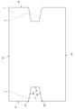
- FIG. 2 is a schematic diagram showing an example of a ceramic substrate having a cutout shape according to an embodiment.
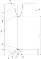
- FIG. 2 is a schematic diagram showing an example of a ceramic substrate having a cutout shape according to an embodiment.
- FIG. 2 is a schematic diagram showing an example of a ceramic substrate having a cutout shape according to an embodiment.
- FIG. 2 is a schematic diagram showing an example of a ceramic substrate having a cutout shape according to an embodiment.
- FIG. 2 is a schematic diagram showing an example of a ceramic substrate having a cutout shape according to an embodiment.
- FIG. 2 is a schematic diagram showing an example of a ceramic substrate having a cutout shape according to an embodiment.
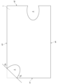
- FIG. 2 is a schematic diagram showing an example of a ceramic substrate having a cutout shape according to an embodiment (comparative example).
- FIG. 2 is a schematic diagram showing an example of a ceramic substrate having a cutout shape according to an embodiment.
- FIG. 2 is a schematic diagram showing an example of a ceramic substrate having a cutout shape according to an embodiment.
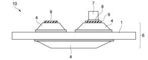
- FIG. 1 is a schematic diagram showing an example of a semiconductor device according to an embodiment.
- FIG. 3 is a schematic diagram showing another example of the semiconductor device according to the embodiment.
- FIG. 2 is a schematic diagram showing an example of a side surface shape of a cutout portion of a ceramic substrate according to an embodiment.
- FIG. 2 is a schematic diagram illustrating the vicinity of a notch portion of a ceramic substrate according to an embodiment.
- FIG. 2 is a schematic side view illustrating a state in which the semiconductor device according to the embodiment is screwed.
- FIG. 2 is a schematic plan view illustrating a state in which the semiconductor device according to the embodiment is screwed.
- 1 is a flowchart illustrating a manufacturing method according to an embodiment.
- An embodiment of the present invention provides a ceramic substrate having a front surface (first surface) and a back surface (second surface) and having at least one notch portion, the ceramic substrate having at least one notch portion, the angle of the end portion of the opening portion being The substrate is characterized in that at least one of the angles ( ⁇ 3 ) of the location where the substrate is present when viewed from the surface is greater than 90 degrees.
- the angle ⁇ 3 is shown in FIG.
- the ceramic substrate according to this embodiment is provided with, for example, one notch and one or more through holes.
- the ceramic substrate may be provided with a plurality of notches at two or more locations. When a plurality of notches are provided, all the notches may have the same shape or may have different shapes. Further, the notch portion may be provided at a corner of the ceramic substrate. When the ceramic substrate is rectangular (rectangular), the cutout portion may be provided on the short side or on the long side. On the other hand, it is more preferable that the number of notches per substrate is 15 or less. If the number of notches exceeds 15, the strength of the ceramic substrate may be insufficient. Further, the shape of the ceramic substrate may be approximately circular, approximately elliptical, or approximately semicircular.
- the cutout includes an opening that opens toward the end of the ceramic substrate.
- a corner of the ceramic substrate is present at the end of the opening (opening end).
- An R section or a C section may be formed at the open end.
- the term "R section or C section may be formed at the opening end” includes forming a minute C section or R section only in the vicinity of the opening end. In the embodiments of the present invention, when a perpendicular line is drawn from the midpoint between the opening ends, there may be a portion where the shape of the cutout part is not symmetrical with respect to the perpendicular line.
- the cutout portion formed in this manner may be combined with a through hole, a cutout portion whose opening is narrower than other parts, a cutout portion whose opening is at a right angle, etc. .
- the determination as to whether ⁇ 3 exceeds 90 degrees is based on the inflection point closest to the opening.
- FIG. 1 is a schematic diagram showing an example of a structure in which a notch shape and a through hole are provided in a ceramic substrate according to an embodiment.
- FIG. 2 is a schematic diagram showing an example of a structure in which a notch shape is provided in a ceramic substrate according to an embodiment.
- reference numeral 1 is a ceramic substrate
- reference numeral 2 is a notch.
- Reference numeral 3 is a through hole.
- Symbol P1 is a first opening end.
- P2 is the second open end.
- the symbol Li indicates an imaginary straight line connecting the first open end P1 and the second open end P2.
- the symbol ⁇ 1 is the angle of the notch (surrounded by the substrate portion) formed by the straight line Li and the notch portion 2 .
- FIG. 2 shows a structure in which the cutout 2 is provided so that the side other than the opening OP has a substantially trapezoidal shape. Moreover, FIG. 2 illustrates a combination of the notch part 2 and another notch part 2.
- FIG. 3 to 9 are schematic diagrams showing an example of a structure in which a cutout portion 2 is provided in the ceramic substrate 1 according to the embodiment.
- a structure in which a substantially V-shaped notch portion 2 is provided is illustrated.
- the symbol P3 indicates the end of the notch 2 that is not on the opening side.
- the symbol ⁇ 2 is the angle of the end P3 that is not on the opening side.
- FIG. 4 a structure in which a substantially semicircular notch 2 is formed is illustrated.
- the symbol P4 indicates the midpoint between the open ends.
- the symbol P5 indicates the farthest point among the intersections of the ceramic substrate 1 and a perpendicular line drawn from the midpoint between the open ends.
- Symbol P6 is the intersection of a perpendicular line drawn from the midpoint between the opening ends and the notch 2 having the opening.
- the symbol L1 indicates the distance between the midpoint P4 and the intersection P5.
- the symbol L2 indicates the distance between the midpoint P4 and the intersection P6.
- FIG. 5 is a schematic diagram illustrating a cutout portion 2 having a combination of a substantially U-shape and a substantially V-shape.
- the symbol ⁇ 3 indicates the angle at which the ceramic substrate 1 exists at the end of the notch 2.
- the symbol ⁇ 4 is the angle between the R part and the boundary of the opening, or the angle between the C part and the boundary of the opening.
- the boundary of the opening refers to the boundary between the opening and the ceramic substrate 1.
- FIG. 6 is a schematic diagram illustrating a structure in which two cutout portions 2 do not have the same shape.
- FIG. 7 is a schematic diagram illustrating a structure in which a widely opened notch 2 is formed at a corner of a ceramic substrate 1 as a comparative example. Further, FIG. 7 shows an example in which the other notch 2 has a shape similar to the through hole 3. As shown in FIG. In FIG. 7, the shape of the notched portion is wide open, which reduces the risk of collision when screwing, but the open end of the board becomes sharp. Therefore, there is a possibility that the risk of cracking or chipping during a collision becomes greater than when ⁇ 3 is greater than 90 degrees, which is not preferable. In the example shown in FIG.
- FIG. 8 is a schematic diagram illustrating a structure having an R-shaped chamfered portion at the open end of the notch 2.
- FIG. 9 is a schematic diagram illustrating a structure in which a C-shaped chamfer is provided at the open end of the notch 2. As shown in FIG.
- FIG. 10 is a schematic diagram illustrating a joined body in which conductor portions are provided on the ceramic substrate 1 and joined together.
- numeral 4 is a conductor part
- numeral 5 is an active metal bonding layer
- numeral 6 is a bonded body.
- FIG. 11 is a schematic diagram illustrating a semiconductor device in which a semiconductor element is mounted on the assembly shown in FIG. 10.
- the reference numeral 7 is a semiconductor element
- the reference numeral 8 is a bonding layer (between the semiconductor element and the conductor part)
- the reference numeral 9 is a plating film
- the reference numeral 10 is a semiconductor device.
- FIG. 12 is a schematic diagram showing an example of the side shape of the notch 2 of the ceramic substrate 1. As shown in FIG.
- the angle of the ceramic substrate 1 between the notch 2 and a straight line connecting the opening ends of the same notch 2 is defined as ⁇ 3 .
- the ceramic substrate 1 has a portion where the angle ⁇ 3 is greater than 90 degrees. It is further preferable that the angles ⁇ 3 of both ends of one notch 2 on the opening side are each larger than 90 degrees.
- a more preferable range of the angle ⁇ 3 is 100 degrees or more and 170 degrees or less, and more preferably 100 degrees or more and 160 degrees or less. More preferably, the angle ⁇ 3 is greater than or equal to 120 degrees and less than or equal to 150 degrees. If the angle ⁇ 3 is too small, such as less than 100 degrees, the effect of making the opening angle larger than 90 degrees may not be sufficient. On the other hand, if the angle is larger than 170 degrees, as described above, the area occupied by the end of the shape of the notch 2 becomes too large, and there is a possibility that a sufficient mounting surface for the semiconductor element cannot be secured on the ceramic substrate 1. . Moreover, two angles exist around one opening of the notch 2 in the portion where the ceramic substrate 1 is present. Preferably, the difference between these two angles is less than 20 degrees. Furthermore, it is more preferable that the difference is less than 10 degrees.
- the angle ⁇ 3 at at least one location is larger than 90 degrees. More preferably, each of the angles ⁇ 3 at both ends of the opening in the at least one notch 2 is 90 degrees or more. It is further preferred that all angles ⁇ 3 in the plurality of notches 2 exceed 90 degrees.
- An R section or a C section may be formed at the open end on the substrate center side.
- a straight line consisting of the boundary (inflection point) between the R part or C part and other parts and the open ends Let the angle on the notch 2 side with respect to the above be ⁇ 1 .
- the size of the R section or the C section is not particularly limited, and may be provided only near the opening end.
- FIG. 13(a) and 13(b) are schematic diagrams illustrating the vicinity of the notch portion of the ceramic substrate according to the embodiment. If there is no inflection point, angles ⁇ 1 and ⁇ 3 are determined by the method shown below. As shown in FIG. 13(a), when the shape from the opening end P1 or P2 to the non-opening end P3 is approximately linear, a straight line along the shape and a straight line Li are used. Find angles ⁇ 1 and ⁇ 3 .
- the farthest point from the straight line Li is specified.
- the end P3 corresponds to the farthest point.
- the shape of the notch 2 is approximated by an ellipse E whose long axis is a straight line connecting the farthest point and the straight line Li.
- the notch 2 is approximated to the ellipse E so that the outer edge of the ellipse E best follows the side surface of the notch 2.
- a boundary between a portion where the ellipse E and the notch 2 are common and a portion where the ellipse E and the notch 2 are not common is identified.
- Angles ⁇ 1 and ⁇ 3 are determined using a straight line passing through the boundary and the open end P1 or a straight line passing through the boundary and the open end P2 as a reference.
- the end of the notch 2 that is not on the opening side has a substantially U-shape, a substantially trapezoidal shape, or a substantially V-shape.
- the angle on the notch 2 side is preferably 70 degrees or more. If the angle is less than 70 degrees, cracks may form from this edge.
- the angle of the end that is not on the opening side is defined as angle ⁇ 2 .
- the angle ⁇ 2 is the angle between the side surfaces of the notch portion 2 . The angle ⁇ 2 is shown in FIG.
- the substantially U-shape refers to a shape in which the end, which is not on the opening side, has an R section, as shown in FIGS. 4 and 8, for example.
- the substantially trapezoidal shape refers to a shape having a C portion at the end that is not on the opening side, as shown in FIGS. 1 and 2, for example.
- the cutout portion 2 may have a polygonal shape such as a substantially pentagonal shape or a substantially hexagonal shape.
- the effect of suppressing the occurrence of cracks at this end can be further enhanced.
- the R portion or the C portion of the chamfered portion By having the R portion or the C portion of the chamfered portion, the effect of suppressing the occurrence of cracks at this end portion can be further enhanced. Therefore, it is more preferable to provide the R section or the C section at a location other than the opening side.
- the shape of the end that is not on the opening side is preferably a substantially V-shape (the angle of the substantially V-shape is 70 degrees or more), a substantially trapezoidal shape, or a substantially U-shape.
- the size of the substantially V-shape (the angle of the substantially V-shape is 70 degrees or more), the substantially trapezoidal shape, or the substantially U-shape is arbitrary.
- these shapes may be very small, provided in a small portion of the shape of the notch 2.
- these shapes may be formed over the entire notch portion 2.
- the R portion or the C portion has a substantially U-shape, the effect of suppressing the occurrence of cracks can be further enhanced. Therefore, it is more preferable that the R portion or the C portion has a substantially U-shape.
- the R section refers to a shape in which the corners of the tip of the notch section 2 are rounded off to form a substantially U-shape.
- the tip refers to the end of the notch 2 that is not on the opening side.
- the C portion refers to a shape in which the corner of the tip of the notch portion 2 is cut linearly to form a substantially trapezoidal shape.
- the corner of the notch side formed from the upper base of the trapezoid is 30 degrees or more.
- the ratio between the upper base and the lower base of the substantially trapezoidal shape (upper base/lower base) is 0.1 or more.
- the upper base of the substantially trapezoid is the length of the side of the tip of the notch 2.
- the lower base of the substantially trapezoid is the length of the opening of the notch 2. Therefore, the lower base of the substantially trapezoid has the length of a straight line connecting the open ends. By doing this, it is possible to further reduce the possibility of cracking or chipping of the ceramic substrate 1 compared to when the ceramic substrate 1 having a substantially V-shape is fixed with screws.
- the shape of the portion that is not on the opening side can be determined by looking from the surface, similar to the angle ⁇ 3 . Further, the shape of the side surface of the portion other than the opening side is determined based on the shape when viewed from the surface formed by the side surface of the notch 2. The shape may also have an R section or a C section.
- the ceramic substrate 1 may have a rectangular or square shape. When an opening is provided at a corner, the ceramic substrate 1 may become partially thin at the opening end. In such cases, it may be difficult to maintain sufficient strength at the corners. Therefore, with respect to the angles of both ends of the opening, it is preferable that a portion of the ceramic substrate 1 is provided where the internal angle is 100 degrees or more.
- the side shape is also controlled.
- the side surface shape it is preferable that at least one or more portions of the front end of the ceramic substrate 1 and the back end of the ceramic substrate 1 have an R portion or a C portion.
- both end portions on the front side have minute R portions or C portions, as shown in FIG. 12 .
- the width of the notch portion 2 may be increased and the notch portion 2 may be open at both the end portion on the front side and the end portion on the back side.
- the arithmetic mean roughness Ra of this side surface is preferably 1.2 ⁇ m or less. Furthermore, it is preferable that the maximum height Rz of this side surface is 2.0 ⁇ m or less. Ra and Rz are described in JISB 0601:2013. JIS B 0601:2013 corresponds to ISO 4287:1997/AMENDMENT 1:2009 (IDT). By adjusting the processing method, surface roughness caused by processing can be controlled. Therefore, it is preferable that the arithmetic mean roughness Ra of the side surface is 1.2 ⁇ m or less, and the maximum height Rz of the side surface is 2.0 ⁇ m or less.
- Examples of methods for controlling surface roughness caused by processing include a method of performing blasting or honing treatment after processing, and a method of controlling the irradiation diameter or energy density during laser processing. By controlling the surface roughness of the side surface portion, the efficiency of screwing can be improved.
- the midpoint between the ends of the opening OP is defined as P4.
- the point of the end of the ceramic substrate 1 farthest from the midpoint P4 is defined as P5.
- L1 be the length of the ceramic substrate 1 between the midpoint P4 and the intersection P5.
- the intersection of the perpendicular line and the notch 2 having the opening is defined as P6.
- L 2 /L 1 is 0.1 or more and 0.4 or less. .
- the end of the ceramic substrate 1 farthest from the midpoint P4 in the combination of the notch 2 and the through hole 3, when the through hole 3 was on a perpendicular line drawn from the midpoint P4, the through hole 3 was ignored.
- the end of the ceramic substrate 1 is defined as an intersection point P5.
- a perpendicular line drawn from the midpoint between one end (first opening end P1) and the other end (second opening end P2) of the opening does not intersect with any other notch 2.
- the length formed by the intersection of this perpendicular line and the ceramic substrate 1 is defined as L1 .
- L1 the distance between the straight line connecting the opening ends of the other notches 2 and the midpoint between the opening ends.
- L2 the longest distance at the intersection with the edge of the notch 2 .
- L 2 /L 1 is preferably 0.1 or more and 0.4 or less.
- L 2 /L 1 is 0.1 or more and 0.35 or less.
- L 2 /L 1 is larger than 0.4, the ceramic substrate 1 may be easily broken.
- L 2 /L 1 is smaller than 0.1, the effect of providing the cutout portion 2 may not be sufficiently obtained.
- the length L 1 when the notch 2 is not located at a corner and there is only one location where the notch 2 is present corresponds to the length of the ceramic substrate 1 .
- the maximum width of the notch 2 when viewed from the side is L3, and the smallest width of the opening width of the notch 2 including the maximum width L3 is L4.
- the direction of the width L3 is parallel to the direction of the width L4, and is parallel to the direction connecting the first open end P1 and the second open end P2. If L4/L3 is smaller than 0.5, there is a possibility that the opening end will be easily chipped.
- L4/L3 is 1 or more, the effect of making the angle of the opening larger than 90 degrees cannot be sufficiently obtained, and the positional accuracy of the screwed portion may deteriorate. It is further preferable that the L4/L3 satisfies 0.7 ⁇ L4/L3 ⁇ 1.
- FIG. 14 is a schematic side view illustrating a state in which the semiconductor device according to the embodiment is screwed.
- FIG. 15 is a schematic plan view illustrating a state in which the semiconductor device according to the embodiment is screwed.
- reference numeral 11 indicates a screw. As shown in FIGS. 14 and 15, when fixing the semiconductor device 10, a screw is passed through the notch 2. Ceramic substrate 1 is pressed toward the support plate by screws 11, and semiconductor device 10 is fixed to the support plate.
- the screw 11 when the screw 11 is provided in the notch 2 of the ceramic substrate 1, the screw 11 is unlikely to collide with the ceramic substrate 1. Further, since the angle ⁇ 3 is larger than 90 degrees, even if the screw 11 collides with the ceramic substrate 1, it is possible to avoid applying a large force locally to the ceramic substrate 1. Thereby, occurrence of chipping or cracking in the ceramic substrate 1 can be suppressed.
- the ceramic substrate 1 contains as a main component one or two selected from silicon nitride, aluminum nitride, sialon, alumina, and zirconia.
- the main component refers to a component contained in an amount of 50% by mass or more.
- the ceramic substrate is one of a silicon nitride substrate, an aluminum nitride substrate, and an algyl substrate.
- Arsil is a material containing a total of 50% by mass or more of two types, alumina and zirconia.
- the thickness of the ceramic substrate 1 is preferably 0.1 mm or more and 3 mm or less, more preferably 0.1 mm or more and 1 mm or less. If the thickness of the ceramic substrate 1 is less than 0.1 mm, the strength of the ceramic substrate 1 may decrease. If the thickness of the ceramic substrate 1 is thicker than 3 mm, the ceramic substrate 1 itself becomes a thermal resistor, which may reduce the heat dissipation performance of the ceramic circuit board.
- the three-point bending strength of the silicon nitride substrate is preferably 600 MPa or more.
- the thermal conductivity of the silicon nitride substrate is preferably 80 W/m ⁇ K or more.
- the substrate thickness can be reduced. Therefore, the three-point bending strength of the silicon nitride substrate is preferably 600 MPa or more, and more preferably 700 MPa or more.
- the thickness of the silicon nitride substrate can be reduced to 0.40 mm or less, and even 0.30 mm or less. Further, the three-point bending strength of the aluminum nitride substrate is about 300 to 450 MPa.
- the thermal conductivity of the aluminum nitride substrate is 160 W/m ⁇ K or more. Since the aluminum nitride substrate has low strength, the substrate thickness is preferably 0.60 mm or more.
- the three-point bending strength of an aluminum oxide substrate is about 300 to 450 MPa, but aluminum oxide substrates are inexpensive among ceramic substrates.
- the three-point bending strength of the Algyl substrate is high, about 550 MPa, but its thermal conductivity is about 30 to 50 W/m ⁇ K.
- the Algyl substrate is a substrate made of a sintered body of a mixture of aluminum oxide and zirconium oxide.
- the ceramic substrate is a nitrogen-containing ceramic substrate.
- nitride ceramics are more preferred, and either a silicon nitride substrate or an aluminum nitride substrate is even more preferred.
- the thickness of the ceramic substrate is preferably 0.1 mm or more and 1 mm or less. If the substrate thickness is less than 0.1 mm, the strength may be insufficient. Furthermore, if the substrate thickness is greater than 1 mm, the ceramic substrate 1 itself becomes a thermal resistor, which may reduce the heat dissipation performance of the circuit board.
- the cutout portion 2 of the ceramic substrate 1 according to the embodiment of the present invention can be suitably used for screwing.
- the silicon nitride substrate preferably has a three-point bending strength of 600 MPa or more.
- the thermal conductivity is preferably 80 W/m ⁇ K or more.
- the substrate thickness can be reduced. Therefore, the three-point bending strength of the silicon nitride substrate is preferably 600 MPa or more, more preferably 700 MPa or more.
- the thickness of the silicon nitride substrate can be reduced to 0.40 mm or less, and further to 0.30 mm or less.
- the three-point bending strength of the aluminum nitride substrate is about 300 to 450 MPa.
- the thermal conductivity of the aluminum nitride substrate is 160 W/m ⁇ K or more. Since the aluminum nitride substrate has low strength, the substrate thickness is preferably 0.60 mm or more.
- the three-point bending strength of an aluminum oxide substrate is about 300 to 450 MPa, aluminum oxide substrates are inexpensive.
- the three-point bending strength of the Algyl substrate is high, about 550 MPa, but the thermal conductivity is about 30 to 50 W/m ⁇ K.
- the Algyl substrate is a substrate made of a sintered body of a mixture of aluminum oxide and zirconium oxide.
- the conductor portion 4 may be bonded to the ceramic substrate 1 having the above-mentioned notch portion 2.
- the cutout portion 2 having the shape described above may be formed in the joined body 6 in which the ceramic substrate 1 and the conductor portion 4 are bonded together.
- the conductor portion 4 may be provided only on one side of the ceramic substrate 1.
- the conductor portions 4 may be provided on both sides of the ceramic substrate 1, respectively.
- the conductor portion 4 provided on the surface of the ceramic substrate 1 is referred to as a front conductor portion.
- the conductor portion 4 provided on the back surface of the ceramic substrate 1 is referred to as a back conductor portion.
- the composition of the front conductor portion and the composition of the back conductor portion may be different from each other.
- composition of the front conductor part and the composition of the back conductor part are the same, it is possible to provide a joined body that is easy to use. For this reason, it is more preferable that the composition of the front conductor portion and the composition of the back conductor portion be the same.
- the conductor part 4 is a copper member or an aluminum member.
- the copper member is made of copper or a copper alloy.
- the copper member is a copper plate, a copper alloy plate, a copper plate with a circuit shape, or a copper alloy plate with a circuit shape.
- the aluminum member is made of aluminum or an aluminum alloy.
- the aluminum member is an aluminum plate, an aluminum alloy plate, an aluminum plate with a circuit shape, or an aluminum alloy plate with a circuit shape.
- a member manufactured by adding a circuit shape to a copper plate is called a copper circuit.
- a member manufactured by adding a circuit shape to an aluminum plate is called an aluminum circuit.
- An advantage of using aluminum for the conductor portion 4 is that it is lower in cost than copper.
- an Al-based brazing material such as an Al--Mg alloy brazing material can be used.
- copper members have higher thermal conductivity than aluminum members. For this reason, it is preferable to use a copper member for the conductor portion 4.
- the conductor portion 4 may be a metallized layer or a conductive thin film other than a copper member or an aluminum member.
- the metallized layer is formed by firing a metal paste.
- the thickness of the conductor portion 4 may be 0.3 mm or more, and further 0.6 mm or more. By increasing the thickness of the conductor portion 4, the heat dissipation of the joined body 6 can be improved.
- the thickness of the front conductor portion may be the same as the thickness of the back conductor portion, or may be different from the thickness of the back conductor portion.
- a copper member is particularly preferable.
- the copper member is made of oxygen-free copper. Oxygen-free copper has a copper purity of 99.96% by mass or more as shown in JIS-H-3100.
- the ceramic substrate 1 and the copper member may be directly joined.
- a punched copper plate may be joined to the ceramic substrate 1.
- a copper plate may be bonded to the ceramic substrate 1, and then the copper plate may be etched.
- a brazing material is used for bonding, it is preferable that the ceramic substrate 1 and the copper member be bonded via a bonding layer containing titanium.
- an active metal brazing material containing Ti is used.
- the active metal brazing material contains, for example, silver or copper as a main component (50% by mass or more), and also contains Ti.
- the ceramic substrate and the copper member are bonded via a bonding layer containing carbon.
- a bonding layer containing carbon can be formed.
- the fluidity of the brazing material can be improved. Thereby, bonding strength can be improved.
- the active metal brazing material may be a brazing material that is a combination of Ag and Ti or a brazing material that is a combination of copper and Ti.
- the active metal brazing material may contain Ag (silver) from 0% by mass to 98% by mass, Cu (copper) from 1% by mass to 85% by mass, and Ti (titanium) or TiH 2 (titanium hydride) from 1% to 85% by mass. The content is preferably 15% by mass or more.
- Nb or Zr may be used instead of Ti, or Nb or Zr may be added to the active metal brazing material in addition to Ti.
- the active metal brazing material preferably contains Ti (titanium) or TiH 2 (titanium hydride) in an amount of 1% by mass or more and 15% by mass or less.
- Ti and TiH 2 titanium hydride
- the content of Ag is preferably 20% by mass or more and 70% by mass or less
- the content of Cu is preferably 15% by mass or more and 65% by mass or less.
- the brazing filler metal may contain 1% by mass or more and 50% by mass or less of one or more selected from Sn (tin), In (indium), and Mn (manganese), if necessary.
- the content of Ti or TiH 2 is preferably 1% by mass or more and 15% by mass or less.
- the brazing filler metal may contain C (carbon) in an amount of 0.1% by mass or more and 2% by mass or less, if necessary.
- the composition ratio of the active metal brazing material is calculated based on the total of the solid raw materials to be mixed as 100% by mass.
- This solid raw material is preferably in powder form.
- the active metal brazing material is composed of three types of Ag, Cu, and Ti
- Ag+Cu+Ti 100% by mass.
- the active metal brazing material is composed of four types of Ag, Cu, TiH 2 and In
- Ag+Cu+TiH 2 +In 100% by mass.
- the active metal brazing material is composed of five types of Ag, Cu, Ti, Sn, and C
- Ag+Cu+Ti+Sn+C 100% by mass.
- the prepared brazing material paste is applied onto the ceramic substrate 1, and the conductor portion 4 is placed on top of it.
- the obtained laminate is heated to bond the ceramic substrate 1 and the conductor portion 4 together. Thereby, a joined body 6 is obtained.
- the above-mentioned notch portion 2 may be provided in the thus obtained joined body 6.
- the conductor portion 4 may be provided on the ceramic substrate 1 provided with the cutout portion 2 described above.
- the conductor portion 4 to which a circuit shape has been given in advance may be joined to the ceramic substrate 1.
- a circuit shape may be provided to the conductor portion 4.
- the joined body 6 in which the conductor portion 4 is provided with a circuit shape is also referred to as a ceramic circuit board.
- the side surface of the conductor section described above has an inclined shape. That is, the side surface of the copper member is preferably inclined with respect to the in-plane direction and the thickness direction.
- the in-plane direction is a direction parallel to the bonding surface between the ceramic substrate 1 and the conductor portion.
- the thickness direction is a direction connecting the ceramic substrate 1 and the conductor portion, and is perpendicular to the in-plane direction.
- the conductor part is a copper member.
- the thickness of the bonding layer 5 is preferably in the range of 10 ⁇ m or more and 60 ⁇ m or less.
- the ceramic circuit board preferably has a shape in which the bonding layer 5 protrudes from the side surface of the conductor portion.
- the part of the bonding layer 5 that protrudes is called a bonding layer protruding portion.
- the protruding portion of the bonding layer preferably has a ratio of length L to thickness T (L/T) within a range of 0.5 or more and 3.0 or less.
- the thickness of the protruding portion of the bonding layer is the thickness of the thickest portion of the protruding portion of the bonding layer.
- the length of the bonding layer protruding portion is the length of the longest portion of the bonding layer protruding portion that protrudes from the side surface of the conductor portion.
- the thickness and length of the protruding portion of the bonding layer are measured from an arbitrary cross section of the ceramic copper circuit board.
- the TCT characteristics of the ceramic copper circuit board can be improved by providing the conductor portion with an inclined shape and the bonding layer protruding portion.
- the bonding layer 8 used for bonding the plating film 9 and the semiconductor element 7 or the conductor portion 4 and the semiconductor element 7 examples thereof include a bonding layer using copper or tin, a bonding layer using solder paste or silver paste. It will be done.
- FIG. 11 shows a structure in which the plating film 9 is provided, the plating film 9 may not be provided.
- the ceramic substrate 1 is a silicon nitride substrate with a thickness of 0.4 mm or less, and the thickness of the conductor portion is preferably 0.6 mm or more.
- a thin silicon nitride substrate with a thickness of 0.4 mm or less has the effect of lowering the thermal resistance of the ceramic substrate. Further, if the copper plate is thicker than 0.6 mm, heat dissipation is improved. Furthermore, if the silicon nitride substrate has a three-point bending strength of 600 MPa or more, the effect can be easily obtained. Therefore, a silicon substrate with a thickness of 0.4 mm or less and a thick copper plate with a thickness of 0.6 mm or more may be combined.
- the method for forming the notch 2 can be arbitrarily selected as long as the notch 2 described above can be formed.
- the notch 2 can be formed by cutting a part of the ceramic substrate 1 with a laser, by applying pressure during green sheeting to create a recess in the ceramic substrate 1, or by cutting a part of the ceramic substrate 1 with a jig saw. There are ways to cut it out. Among these, the method of forming by laser is more preferable.
- the notch 2 is formed by laser processing, a clear difference in appearance that can be observed by SEM occurs in the ceramic substrate. Therefore, whether or not the cutout portion 2 was formed by laser processing can be determined by observing the cutout portion 2 with an SEM.
- the apparent difference in appearance observed with SEM is due to thermal effects that occur during laser processing.
- the thermally affected portion may be partially removed when honing or the like is performed. Therefore, when the above-described laser machining marks are observed in a portion of the notch 2 (at least a portion of the side surface of the notch 2), it can be determined that the notch 2 was formed by laser machining.
- the energy density of the laser is high. If the energy density of the laser is high, it becomes possible to increase the scanning speed. Moreover, when forming the notch part 2 with a laser, the notch part 2 can be formed with high positional accuracy. Furthermore, by forming the notch 2 by laser processing, when the shape of the notch 2 is viewed from the side of the ceramic substrate 1, it is possible to create a shape in which the front side is open toward the center of the substrate. becomes.
- Lasers used are not particularly limited, but include CO2 laser, YAG laser (fundamental wave, double wave, triple wave, quadruple wave), femtosecond laser, picosecond laser, semiconductor laser, LD laser, excimer laser. , YVO4 laser, and DDL laser.
- CO2 laser YAG laser
- femtosecond laser picosecond laser
- semiconductor laser LD laser
- excimer laser LD laser
- YVO4 laser excimer laser.
- DDL laser DDL laser.
- the notch portion 2 may be formed by one laser irradiation, or the notch portion 2 may be formed by multiple laser irradiations. Dust collection or assist gas may be used as necessary.
- the laser may be irradiated from only one side of the ceramic substrate 1, or may be irradiated from both sides of the ceramic substrate 1.
- positional accuracy with respect to the first irradiation surface is important. Therefore, it is more preferable to irradiate the laser from only one side of the ceramic substrate 1.
- a continuous groove may be provided, or a dot-shaped laser beam may be irradiated.
- continuous grooves are preferable.
- the output mode of the laser may be pulsed or CW (continuous), or a combination of both. It may be irradiated multiple times to penetrate.
- the maximum depth of the grooves be controlled with respect to the thickness of the substrate.
- the thickness of the substrate be t, and the maximum depth of the groove be d.
- the maximum depth of the groove is expressed as the total value when the laser is irradiated from both the front and back surfaces of the ceramic substrate 1.
- d/t is 1.0. That is, more preferably, the grooves are present on both the front and back surfaces.
- the depth d of the groove is always 1.0 with respect to the thickness t of the substrate (the groove penetrates through).
- a separation process is performed to separate the notch 2 side from the ceramic substrate 1 in order to form the notch 2.
- a separation process is performed to separate the notch 2 side from the ceramic substrate 1 in order to form the notch 2.
- the surface roughness of the side surface of the ceramic substrate 1 and the surface roughness of the side surface of the notch 2 may be different.
- the difference between the average value of the side surface portion of the substrate and the average value of the side surface portion of the notch portion 2 is 3.0 ⁇ m or less.
- the ceramic substrate 1 may be honed if necessary. As long as the ceramic substrate has been sintered, the honing may be performed before or after the notch 2 is formed.
- the timing of forming the notch 2 is not particularly limited. If the cutout portion 2 is formed during the green sheet, the positional accuracy of the cutout portion 2 may be reduced due to the subsequent sintering process. Therefore, the timing of forming the notch portion 2 is preferably after sintering.
- the cutout portion 2 may be formed after the conductor portion 4 is joined, or may be formed before the conductor portion 4 is joined. As shown in FIG. 7, when the cutout portion 2 is provided at a corner, the substrate portion has a sharp-pointed shape. If the screw collides with the open end when screwing, there is a possibility that the ceramic substrate 1 will be chipped. For this reason, a structure in which the cutout portions 2 are provided at the corners is not preferable.
- the notch 2 is formed so that the width of the notch 2 on the opening OP side is wider than the width of the end on the side other than the opening. is preferably formed. More specifically, regarding the shape of the notch 2, when the distance parallel to the line connecting the opening ends is defined as the "width", Wa is the average value of the width of the entire notch 2.
- the width of the opening be Wo. In this case, it is preferable to satisfy 1.01 ⁇ Wo/Wa ⁇ 5.0. It is more preferable to satisfy 1.2 ⁇ Wo/Wa ⁇ 4.0. More preferably, 1.5 ⁇ Wo/Wa ⁇ 3.5 is satisfied.
- the width of the notch 2 is controlled as described above, it is possible to prevent the opening from becoming too wide, and to control the degree of opening of the opening. It becomes easier to obtain the effect of controlling the angle of the portion of the opening where the substrate is present. Further, by controlling the shape of the notch 2, the torque when screwing can be increased.
- FIG. 16 is a flowchart illustrating the manufacturing method according to the embodiment.
- FIG. 16 shows a preferred example of the manufacturing method according to the embodiment.
- a ceramic substrate 1 is prepared (step St1). Ceramic substrate 1 can be manufactured by the method described above.
- a cutout portion 2 is formed in the prepared ceramic substrate 1 (step St2).
- the conductor portion 4 is bonded to the ceramic substrate 1 (step St3).
- the conductor portion 4 is etched to give a circuit shape (Step St4).
- the semiconductor element 7 is mounted on the conductor portion 4 (step St5).
- the semiconductor device 10 is obtained.
- a screw is passed through the notch 2 and the semiconductor device 10 is fixed by screwing (step S6). Note that, as described above, the order of each step and the specific process executed in each step can be changed as appropriate.
- the ceramic substrate 1 has a front surface 1a (first main surface) and a back surface 1b (second main surface), as shown in FIG.
- the back surface 1b is located on the opposite side of the front surface 1a.
- the ceramic substrate 1 has side surfaces s1 to s4.
- the side surfaces s1 to s4 are connected to the front surface 1a and the back surface 1b.
- the side surfaces s1 to s4 are parallel to the thickness direction connecting the front surface 1a and the back surface 1b.
- the side surface s1 and the side surface s2 are parallel to each other, and the side surface s3 and the side surface s4 are parallel to each other.
- the notch 2 is provided on at least one of the side surfaces s1 to s4, and penetrates the ceramic substrate 1 from the front surface 1a to the back surface 1b.
- one of the plurality of notches 2 has a first surface 2a and a second surface 2b that are continuous with the side surface s1 of the ceramic substrate 1.
- the first surface 2a and the second surface 2b are at least part of the side surfaces of the notch portion 2.
- the first surface 2a and the second surface 2b are parallel to the thickness direction of the ceramic substrate 1 and are inclined with respect to the side surface s1.
- the first surface 2a and the second surface 2b face each other in a direction parallel to the side surface s1.
- the width of the notch portion 2 becomes narrower as it moves away from the side surface s1.
- the first open end P1 is located between the side surface s1 and one end of the first surface 2a.
- the second open end P2 is located between the side surface s1 and one end of the second surface 2b.
- the width of the notch portion 2 corresponds to the distance between the first surface 2a and the second surface 2b in the direction parallel to the side surface s1.
- the cutout portion 2 may further include a third surface 2c.
- the third surface 2c is continuous with the first surface 2a and the second surface 2b, and is located between the other end of the first surface 2a and the other end of the second surface 2b.
- the third surface 2c is parallel to the side surface s1.
- the angle ⁇ 1 is also the angle between the straight line Li and the first surface 2a.
- the angle ⁇ 2 is also the angle between the first surface 2a and the third surface 2c or the angle between the second surface 2b and the third surface 2c.
- the angle ⁇ 3 is also the angle between the side surface s1 and the first surface 2a at the first open end P1, or the angle between the side surface s1 and the second surface 2b at the second open end P2.
- the cutout portion 2 does not have the third surface 2c.
- the angle ⁇ 2 is the angle between the first surface 2a and the second surface 2b.
- the first surface 2a and the second surface 2b may be flat as shown in FIGS. 1 to 3, or may be curved as shown in FIG. 4.
- the other end of the first surface 2a and the other end of the second surface 2b are connected.
- the cutout portion 2 may have a concave surface 2d depressed toward the center of the ceramic substrate 1.
- the first surface 2a and the second surface 2b are continuous with the concave surface 2d.
- the angle ⁇ 4 is also the angle between the other end of the first surface 2a and one end of the concave surface 2d, or the angle between the other end of the second surface 2b and the other end of the concave surface 2d.
- the length L3 shown in FIG. 12 is also the distance between a part of the first surface 2a and a part of the second surface 2b.
- the part of the first surface 2a and the part of the second surface 2b face each other in a direction parallel to the side surface s1.
- the length L4 is also the distance between another part of the first surface 2a and another part of the second surface 2b.
- the other part of the first surface 2a and the another part of the second surface 2b face each other in a direction parallel to the side surface s1.
- the part of the first surface 2a is located on the surface 1a side with respect to the other part of the first surface 2a.
- the part of the second surface 2b is located on the surface 1a side with respect to the other part of the second surface 2b.
- Example 1 (Example) (Examples 1-6, Comparative Examples 1-2) Table 1 lists the types and thicknesses of the ceramic substrates used.
- the thermal conductivity of the silicon nitride substrate is 90 W/m ⁇ K, and the three-point bending strength is 700 MPa.
- the aluminum nitride substrate has a thermal conductivity of 170 W/m ⁇ K and a three-point bending strength of 400 MPa.
- the thermal conductivity of the alumina (aluminum oxide) substrate is 25 W/m ⁇ K, and the three-point bending strength is 450 MPa.
- the thermal conductivity of the zirconia (zirconium oxide) substrate is 25 W/m ⁇ K, and the three-point bending strength is 500 MPa.
- the Algyl substrate has a thermal conductivity of 25 W/m ⁇ K and a three-point bending strength of 550 MPa.
- Table 2 shows the shapes of the cutout portions 2 in the Examples and Comparative Examples listed in Table 1.
- Table 2 shows the angle ⁇ 1 of the opening end on the notch 2 side, the angle ⁇ 2 of the end of the notch 2 not on the opening side, the angle ⁇ 3 of the opening end on the ceramic substrate 1 side, and the opening
- the shape of the end of the notch 2 that is not on the C part side, the angle of the boundary between the C part and the opening, and L 2 /L 1 are described. Examples in which the angle ⁇ 2 is described as 90 degrees or more indicate that the end of the notch 2 that is not on the opening side is rounded. Furthermore, in the case of the R shape, the angle ⁇ 2 is found to be larger than 90 degrees because the inflection point can be used as the reference point of the substrate portion.
- the angle ⁇ 1 is the angle on the notch side of the open end of the ceramic substrate 1, and is the angle at the part of the notch 2 where the substrate does not exist (the cutout part). be.
- the angle ⁇ 2 refers to the angle of the portion where the ceramic substrate 1 does not exist at the end P3 of the notch portion 2 that is not on the opening side.
- the angle ⁇ 3 is the angle on the side where the ceramic substrate 1 is present at the open end.
- the shape of the end of the notch 2 that is not on the opening side refers to the shape of the portion including P3.
- the U-shape was described as an R-shape (substantially U-shape).
- the approximately trapezoidal shape was described as a C shape.
- the V-shape is described as an approximately V-shape.
- Table 2 the angle of the boundary between the C portion and the opening indicates the shape of the boundary between the C portion and the R portion or the boundary between the C portion and the approximately V-shaped portion. If the boundary part was curved, it was described as "no boundary".
- the presence or absence of cracks and cracks was examined on the laser-processed surfaces and fractured surfaces of the notches 2 provided at four locations per substrate. That is, the presence or absence of cracks and fractures in the notch portions 2 at 400 locations was examined. In addition, the presence or absence of burrs exceeding the tolerance on the side surface of the notch portion 2 was examined. The incidence of burrs, chips, and cracks was investigated for each example.
- Table 4 shows the results of measuring the arithmetic surface roughness Ra and maximum surface roughness Rz of the side surface of the notch.
- the side surface of the notch 2 is a surface of the notch 2 that is parallel to the thickness direction of the substrate.
- the shape of the notch 2 is the shape when the notch 2 is viewed from above.
- the opening end is the shape of the opening on the side where the substrate is present.
- Opening End P4 that is not on the side P4...The midpoint between the open ends P5...The farthest intersection of the intersections of the perpendicular line drawn from the midpoint between the open ends and the board P6...Drawed from the midpoint between the open ends Intersection between the perpendicular line and the cutout having the opening
Landscapes
- Engineering & Computer Science (AREA)
- Microelectronics & Electronic Packaging (AREA)
- Chemical & Material Sciences (AREA)
- Ceramic Engineering (AREA)
- Inorganic Chemistry (AREA)
- Manufacturing & Machinery (AREA)
- Physics & Mathematics (AREA)
- Optics & Photonics (AREA)
- Structure Of Printed Boards (AREA)
Priority Applications (5)
| Application Number | Priority Date | Filing Date | Title |
|---|---|---|---|
| EP23780746.6A EP4503114A4 (en) | 2022-03-30 | 2023-03-29 | CERAMIC SUBSTRATE, ASSEMBLED BODY, SEMICONDUCTOR DEVICE, METHOD FOR MANUFACTURING CERAMIC SUBSTRATE, AND METHOD FOR MANUFACTURING CERAMIC PRINTED CIRCUIT BOARD |
| CN202380014871.6A CN118414697A (zh) | 2022-03-30 | 2023-03-29 | 陶瓷基板、接合体、半导体装置、陶瓷基板的制造方法及陶瓷电路基板的制造方法 |
| JP2024512711A JP7804753B2 (ja) | 2022-03-30 | 2023-03-29 | セラミックス基板、接合体、半導体装置、セラミックス基板の製造方法、およびセラミックス回路基板の製造方法 |
| US18/670,986 US20240324105A1 (en) | 2022-03-30 | 2024-05-22 | Ceramic substrate, joined body, semiconductor device, method for manufacturing ceramic substrate, and method for manufacturing ceramic circuit board |
| JP2025167502A JP2025182048A (ja) | 2022-03-30 | 2025-10-03 | 半導体モジュールの製造方法及び窒化珪素基板 |
Applications Claiming Priority (2)
| Application Number | Priority Date | Filing Date | Title |
|---|---|---|---|
| JP2022-055240 | 2022-03-30 | ||
| JP2022055240 | 2022-03-30 |
Related Child Applications (1)
| Application Number | Title | Priority Date | Filing Date |
|---|---|---|---|
| US18/670,986 Continuation US20240324105A1 (en) | 2022-03-30 | 2024-05-22 | Ceramic substrate, joined body, semiconductor device, method for manufacturing ceramic substrate, and method for manufacturing ceramic circuit board |
Publications (1)
| Publication Number | Publication Date |
|---|---|
| WO2023190738A1 true WO2023190738A1 (ja) | 2023-10-05 |
Family
ID=88202707
Family Applications (1)
| Application Number | Title | Priority Date | Filing Date |
|---|---|---|---|
| PCT/JP2023/012928 Ceased WO2023190738A1 (ja) | 2022-03-30 | 2023-03-29 | セラミックス基板、接合体、半導体装置、セラミックス基板の製造方法、およびセラミックス回路基板の製造方法 |
Country Status (5)
| Country | Link |
|---|---|
| US (1) | US20240324105A1 (https=) |
| EP (1) | EP4503114A4 (https=) |
| JP (2) | JP7804753B2 (https=) |
| CN (1) | CN118414697A (https=) |
| WO (1) | WO2023190738A1 (https=) |
Citations (6)
| Publication number | Priority date | Publication date | Assignee | Title |
|---|---|---|---|---|
| JP2005056933A (ja) | 2003-08-06 | 2005-03-03 | Ngk Spark Plug Co Ltd | 放熱部材、回路基板および半導体装置 |
| JP2005159083A (ja) * | 2003-11-27 | 2005-06-16 | Kyocera Corp | 多数個取り配線基板 |
| WO2011004798A1 (ja) * | 2009-07-06 | 2011-01-13 | 株式会社 東芝 | 素子搭載用セラミックス基板、led搭載用セラミックス基板、ledランプ及びヘッドライト並びに電子部品 |
| JP2015065431A (ja) * | 2013-08-30 | 2015-04-09 | 日亜化学工業株式会社 | 発光素子搭載用基板及び該基板の固定方法 |
| JP2020088245A (ja) * | 2018-11-28 | 2020-06-04 | 京セラ株式会社 | 配線基板、電子装置および電子モジュール |
| JP2021185611A (ja) * | 2015-03-31 | 2021-12-09 | 日立金属株式会社 | 窒化珪素系セラミックス集合基板 |
Family Cites Families (5)
| Publication number | Priority date | Publication date | Assignee | Title |
|---|---|---|---|---|
| FR2555394B1 (fr) * | 1983-11-22 | 1986-03-28 | Eurofarad | Support pour composant rapide, notamment composant hyperfrequence, a elements de decouplage incorpores |
| JP4755754B2 (ja) | 2000-12-06 | 2011-08-24 | 株式会社東芝 | 窒化珪素基板およびそれを用いた窒化珪素回路基板並びにその製造方法 |
| JP4078042B2 (ja) * | 2001-06-12 | 2008-04-23 | ローム株式会社 | 複数の素子を有するチップ型電子部品の製造方法 |
| JP2006203108A (ja) | 2005-01-24 | 2006-08-03 | Hitachi Metals Ltd | セラミックス回路基板の接合構造およびパワーモジュール |
| JP5379465B2 (ja) * | 2008-12-17 | 2013-12-25 | パナソニック株式会社 | 発光装置 |
-
2023
- 2023-03-29 EP EP23780746.6A patent/EP4503114A4/en active Pending
- 2023-03-29 WO PCT/JP2023/012928 patent/WO2023190738A1/ja not_active Ceased
- 2023-03-29 CN CN202380014871.6A patent/CN118414697A/zh active Pending
- 2023-03-29 JP JP2024512711A patent/JP7804753B2/ja active Active
-
2024
- 2024-05-22 US US18/670,986 patent/US20240324105A1/en active Pending
-
2025
- 2025-10-03 JP JP2025167502A patent/JP2025182048A/ja active Pending
Patent Citations (6)
| Publication number | Priority date | Publication date | Assignee | Title |
|---|---|---|---|---|
| JP2005056933A (ja) | 2003-08-06 | 2005-03-03 | Ngk Spark Plug Co Ltd | 放熱部材、回路基板および半導体装置 |
| JP2005159083A (ja) * | 2003-11-27 | 2005-06-16 | Kyocera Corp | 多数個取り配線基板 |
| WO2011004798A1 (ja) * | 2009-07-06 | 2011-01-13 | 株式会社 東芝 | 素子搭載用セラミックス基板、led搭載用セラミックス基板、ledランプ及びヘッドライト並びに電子部品 |
| JP2015065431A (ja) * | 2013-08-30 | 2015-04-09 | 日亜化学工業株式会社 | 発光素子搭載用基板及び該基板の固定方法 |
| JP2021185611A (ja) * | 2015-03-31 | 2021-12-09 | 日立金属株式会社 | 窒化珪素系セラミックス集合基板 |
| JP2020088245A (ja) * | 2018-11-28 | 2020-06-04 | 京セラ株式会社 | 配線基板、電子装置および電子モジュール |
Non-Patent Citations (1)
| Title |
|---|
| See also references of EP4503114A4 |
Also Published As
| Publication number | Publication date |
|---|---|
| EP4503114A4 (en) | 2026-03-25 |
| JP2025182048A (ja) | 2025-12-11 |
| US20240324105A1 (en) | 2024-09-26 |
| CN118414697A (zh) | 2024-07-30 |
| JP7804753B2 (ja) | 2026-01-22 |
| JPWO2023190738A1 (https=) | 2023-10-05 |
| EP4503114A1 (en) | 2025-02-05 |
Similar Documents
| Publication | Publication Date | Title |
|---|---|---|
| JP5273922B2 (ja) | 放熱部材および半導体装置 | |
| JP7208161B2 (ja) | 低アモルファス相を有するセラミック-金属基板 | |
| EP3615259B1 (en) | Method of laser ablation of a metal-ceramic substrate | |
| EP2282334B1 (en) | Method for producing substrate for power module | |
| JP6587205B2 (ja) | 窒化珪素セラミックス集合基板及びその製造方法、並びに窒化珪素セラミックス焼結基板の製造方法 | |
| WO2020138283A1 (ja) | セラミックス-銅複合体、セラミックス回路基板、パワーモジュール及びセラミックス-銅複合体の製造方法 | |
| JP4124040B2 (ja) | 半導体装置 | |
| JP7804753B2 (ja) | セラミックス基板、接合体、半導体装置、セラミックス基板の製造方法、およびセラミックス回路基板の製造方法 | |
| JP7700077B2 (ja) | セラミックス基板、接合体およびそれを用いた半導体装置 | |
| KR20070024506A (ko) | 칩 저항기 | |
| JPH08274423A (ja) | セラミックス回路基板 | |
| JP7490934B2 (ja) | 回路基板の製造方法及び回路基板 | |
| EP4037865B1 (de) | Verfahren zum bearbeiten und befestigen eines metall-keramik-substrate | |
| WO2025063256A1 (ja) | セラミックススクライブ基板、セラミックススクライブ基板の製造方法、セラミックス基板の製造方法、及び、セラミックス回路基板の製造方法 | |
| WO2025074881A1 (ja) | セラミックススクライブ基板の製造方法、セラミックス基板の製造方法、および、セラミックス回路基板の製造方法 | |
| EP3740047A1 (en) | Ceramic circuit board | |
| JP2003031731A (ja) | セラミックス基板、その製造方法およびセラミックス回路基板 | |
| CN119234305A (zh) | 陶瓷基板、陶瓷电路基板、半导体装置、陶瓷基板的制造方法以及陶瓷分割基板的制造方法 |
Legal Events
| Date | Code | Title | Description |
|---|---|---|---|
| 121 | Ep: the epo has been informed by wipo that ep was designated in this application |
Ref document number: 23780746 Country of ref document: EP Kind code of ref document: A1 |
|
| ENP | Entry into the national phase |
Ref document number: 2024512711 Country of ref document: JP Kind code of ref document: A |
|
| WWE | Wipo information: entry into national phase |
Ref document number: 202380014871.6 Country of ref document: CN |
|
| WWE | Wipo information: entry into national phase |
Ref document number: 2023780746 Country of ref document: EP |
|
| NENP | Non-entry into the national phase |
Ref country code: DE |
|
| ENP | Entry into the national phase |
Ref document number: 2023780746 Country of ref document: EP Effective date: 20241030 |