WO2023190531A1 - 摺動部材、およびこれを用いたギアボックス、風力発電機、ならびに摺動部材の製造方法 - Google Patents
摺動部材、およびこれを用いたギアボックス、風力発電機、ならびに摺動部材の製造方法 Download PDFInfo
- Publication number
- WO2023190531A1 WO2023190531A1 PCT/JP2023/012552 JP2023012552W WO2023190531A1 WO 2023190531 A1 WO2023190531 A1 WO 2023190531A1 JP 2023012552 W JP2023012552 W JP 2023012552W WO 2023190531 A1 WO2023190531 A1 WO 2023190531A1
- Authority
- WO
- WIPO (PCT)
- Prior art keywords
- sliding
- sliding member
- base material
- sliding layer
- matrix
- Prior art date
Links
- 238000004519 manufacturing process Methods 0.000 title claims description 18
- 238000000034 method Methods 0.000 title claims description 16
- 239000000463 material Substances 0.000 claims abstract description 130
- 239000012791 sliding layer Substances 0.000 claims abstract description 108
- 239000002245 particle Substances 0.000 claims abstract description 93
- 239000011159 matrix material Substances 0.000 claims abstract description 49
- 239000000654 additive Substances 0.000 claims description 73
- 230000000996 additive effect Effects 0.000 claims description 66
- 238000003466 welding Methods 0.000 claims description 35
- 239000000853 adhesive Substances 0.000 claims description 11
- 230000001070 adhesive effect Effects 0.000 claims description 11
- 230000008018 melting Effects 0.000 claims description 7
- 238000002844 melting Methods 0.000 claims description 7
- 239000000843 powder Substances 0.000 claims description 6
- 229910052718 tin Inorganic materials 0.000 claims description 6
- 229910052782 aluminium Inorganic materials 0.000 claims description 5
- 150000001875 compounds Chemical class 0.000 claims description 5
- 229910052802 copper Inorganic materials 0.000 claims description 5
- 229910052760 oxygen Inorganic materials 0.000 claims description 4
- 229910052742 iron Inorganic materials 0.000 claims description 3
- 229910052796 boron Inorganic materials 0.000 claims description 2
- 229910052799 carbon Inorganic materials 0.000 claims description 2
- 229910052804 chromium Inorganic materials 0.000 claims description 2
- 238000003754 machining Methods 0.000 claims description 2
- 229910052748 manganese Inorganic materials 0.000 claims description 2
- 229910052750 molybdenum Inorganic materials 0.000 claims description 2
- 229910052759 nickel Inorganic materials 0.000 claims description 2
- 229910052757 nitrogen Inorganic materials 0.000 claims description 2
- 230000002093 peripheral effect Effects 0.000 claims description 2
- 229910052698 phosphorus Inorganic materials 0.000 claims description 2
- 229910052706 scandium Inorganic materials 0.000 claims description 2
- 229910052710 silicon Inorganic materials 0.000 claims description 2
- 229910052719 titanium Inorganic materials 0.000 claims description 2
- 229910052721 tungsten Inorganic materials 0.000 claims description 2
- 229910052726 zirconium Inorganic materials 0.000 claims description 2
- 238000012360 testing method Methods 0.000 description 41
- 238000010586 diagram Methods 0.000 description 15
- 230000000052 comparative effect Effects 0.000 description 10
- 230000013011 mating Effects 0.000 description 10
- 229910045601 alloy Inorganic materials 0.000 description 9
- 239000000956 alloy Substances 0.000 description 9
- 239000007789 gas Substances 0.000 description 9
- 239000010410 layer Substances 0.000 description 8
- 239000002184 metal Substances 0.000 description 6
- 229910052751 metal Inorganic materials 0.000 description 6
- 230000008020 evaporation Effects 0.000 description 5
- 238000001704 evaporation Methods 0.000 description 5
- 239000010953 base metal Substances 0.000 description 4
- 230000007547 defect Effects 0.000 description 4
- 229910000881 Cu alloy Inorganic materials 0.000 description 3
- 238000005299 abrasion Methods 0.000 description 3
- 229910052797 bismuth Inorganic materials 0.000 description 3
- 239000000314 lubricant Substances 0.000 description 3
- 238000012545 processing Methods 0.000 description 3
- 238000005204 segregation Methods 0.000 description 3
- 239000007787 solid Substances 0.000 description 3
- XKRFYHLGVUSROY-UHFFFAOYSA-N Argon Chemical compound [Ar] XKRFYHLGVUSROY-UHFFFAOYSA-N 0.000 description 2
- 229910000831 Steel Inorganic materials 0.000 description 2
- 238000005054 agglomeration Methods 0.000 description 2
- 230000002776 aggregation Effects 0.000 description 2
- 229910052786 argon Inorganic materials 0.000 description 2
- 238000005520 cutting process Methods 0.000 description 2
- 238000009826 distribution Methods 0.000 description 2
- 238000010891 electric arc Methods 0.000 description 2
- 229910052745 lead Inorganic materials 0.000 description 2
- 150000002739 metals Chemical class 0.000 description 2
- 238000005498 polishing Methods 0.000 description 2
- 239000010959 steel Substances 0.000 description 2
- OKTJSMMVPCPJKN-UHFFFAOYSA-N Carbon Chemical compound [C] OKTJSMMVPCPJKN-UHFFFAOYSA-N 0.000 description 1
- 229910000978 Pb alloy Inorganic materials 0.000 description 1
- 229910006639 Si—Mn Inorganic materials 0.000 description 1
- 229910052787 antimony Inorganic materials 0.000 description 1
- 238000013459 approach Methods 0.000 description 1
- QVGXLLKOCUKJST-UHFFFAOYSA-N atomic oxygen Chemical compound [O] QVGXLLKOCUKJST-UHFFFAOYSA-N 0.000 description 1
- 229910002091 carbon monoxide Inorganic materials 0.000 description 1
- 230000006866 deterioration Effects 0.000 description 1
- 239000006185 dispersion Substances 0.000 description 1
- 230000002708 enhancing effect Effects 0.000 description 1
- 238000011156 evaluation Methods 0.000 description 1
- 229910002804 graphite Inorganic materials 0.000 description 1
- 239000010439 graphite Substances 0.000 description 1
- 238000010438 heat treatment Methods 0.000 description 1
- 239000001307 helium Substances 0.000 description 1
- 229910052734 helium Inorganic materials 0.000 description 1
- SWQJXJOGLNCZEY-UHFFFAOYSA-N helium atom Chemical compound [He] SWQJXJOGLNCZEY-UHFFFAOYSA-N 0.000 description 1
- 229910052738 indium Inorganic materials 0.000 description 1
- 239000011261 inert gas Substances 0.000 description 1
- 229910052749 magnesium Inorganic materials 0.000 description 1
- 229910052961 molybdenite Inorganic materials 0.000 description 1
- CWQXQMHSOZUFJS-UHFFFAOYSA-N molybdenum disulfide Chemical compound S=[Mo]=S CWQXQMHSOZUFJS-UHFFFAOYSA-N 0.000 description 1
- 229910052982 molybdenum disulfide Inorganic materials 0.000 description 1
- 239000001301 oxygen Substances 0.000 description 1
- 238000010248 power generation Methods 0.000 description 1
- 239000011347 resin Substances 0.000 description 1
- 229920005989 resin Polymers 0.000 description 1
- 238000007711 solidification Methods 0.000 description 1
- 230000008023 solidification Effects 0.000 description 1
- 239000010935 stainless steel Substances 0.000 description 1
- 229910001220 stainless steel Inorganic materials 0.000 description 1
- 239000000126 substance Substances 0.000 description 1
- 238000012546 transfer Methods 0.000 description 1
- 229910052725 zinc Inorganic materials 0.000 description 1
Images


Classifications
-
- B—PERFORMING OPERATIONS; TRANSPORTING
- B23—MACHINE TOOLS; METAL-WORKING NOT OTHERWISE PROVIDED FOR
- B23K—SOLDERING OR UNSOLDERING; WELDING; CLADDING OR PLATING BY SOLDERING OR WELDING; CUTTING BY APPLYING HEAT LOCALLY, e.g. FLAME CUTTING; WORKING BY LASER BEAM
- B23K9/00—Arc welding or cutting
- B23K9/04—Welding for other purposes than joining, e.g. built-up welding
-
- C—CHEMISTRY; METALLURGY
- C23—COATING METALLIC MATERIAL; COATING MATERIAL WITH METALLIC MATERIAL; CHEMICAL SURFACE TREATMENT; DIFFUSION TREATMENT OF METALLIC MATERIAL; COATING BY VACUUM EVAPORATION, BY SPUTTERING, BY ION IMPLANTATION OR BY CHEMICAL VAPOUR DEPOSITION, IN GENERAL; INHIBITING CORROSION OF METALLIC MATERIAL OR INCRUSTATION IN GENERAL
- C23C—COATING METALLIC MATERIAL; COATING MATERIAL WITH METALLIC MATERIAL; SURFACE TREATMENT OF METALLIC MATERIAL BY DIFFUSION INTO THE SURFACE, BY CHEMICAL CONVERSION OR SUBSTITUTION; COATING BY VACUUM EVAPORATION, BY SPUTTERING, BY ION IMPLANTATION OR BY CHEMICAL VAPOUR DEPOSITION, IN GENERAL
- C23C4/00—Coating by spraying the coating material in the molten state, e.g. by flame, plasma or electric discharge
- C23C4/12—Coating by spraying the coating material in the molten state, e.g. by flame, plasma or electric discharge characterised by the method of spraying
- C23C4/131—Wire arc spraying
-
- F—MECHANICAL ENGINEERING; LIGHTING; HEATING; WEAPONS; BLASTING
- F16—ENGINEERING ELEMENTS AND UNITS; GENERAL MEASURES FOR PRODUCING AND MAINTAINING EFFECTIVE FUNCTIONING OF MACHINES OR INSTALLATIONS; THERMAL INSULATION IN GENERAL
- F16C—SHAFTS; FLEXIBLE SHAFTS; ELEMENTS OR CRANKSHAFT MECHANISMS; ROTARY BODIES OTHER THAN GEARING ELEMENTS; BEARINGS
- F16C33/00—Parts of bearings; Special methods for making bearings or parts thereof
- F16C33/02—Parts of sliding-contact bearings
- F16C33/04—Brasses; Bushes; Linings
- F16C33/06—Sliding surface mainly made of metal
- F16C33/12—Structural composition; Use of special materials or surface treatments, e.g. for rust-proofing
-
- F—MECHANICAL ENGINEERING; LIGHTING; HEATING; WEAPONS; BLASTING
- F16—ENGINEERING ELEMENTS AND UNITS; GENERAL MEASURES FOR PRODUCING AND MAINTAINING EFFECTIVE FUNCTIONING OF MACHINES OR INSTALLATIONS; THERMAL INSULATION IN GENERAL
- F16C—SHAFTS; FLEXIBLE SHAFTS; ELEMENTS OR CRANKSHAFT MECHANISMS; ROTARY BODIES OTHER THAN GEARING ELEMENTS; BEARINGS
- F16C33/00—Parts of bearings; Special methods for making bearings or parts thereof
- F16C33/02—Parts of sliding-contact bearings
- F16C33/04—Brasses; Bushes; Linings
- F16C33/06—Sliding surface mainly made of metal
- F16C33/14—Special methods of manufacture; Running-in
Definitions
- the present disclosure relates to a sliding member, a gearbox using the same, a wind power generator, and a method for manufacturing the sliding member.
- Patent Document 1 Conventionally, it is well known to form sliding members by arc welding (Patent Document 1).
- Patent Document 1 a Cu--Sn--Pb alloy is laminated as a sliding layer on the surface of the back metal by arc welding. At this time, the sliding layer is formed using powder in which Pb is previously dispersed in an alloy matrix.
- Patent Document 1 aims to reduce the evaporation of Pb due to high temperatures during welding, and to form a structure in which Pb is uniformly dispersed in the sliding layer.
- the sliding layer can be formed, for example, by welding using powder or wire in which additives are added to the matrix in advance.
- the low melting point metal added to the matrix tends to evaporate during welding, causing defects and segregation in the matrix of the sliding layer. Further, there is a problem in that the hard material added to the matrix tends to cause agglomeration during welding, making uniform dispersion in the matrix difficult. There is a problem in that uneven distribution of hard particles in the sliding layer causes a decrease in the strength of the sliding layer and deterioration of sliding characteristics.
- an object of the present disclosure is to provide a sliding member in which additive particles are uniformly dispersed in the sliding layer and have high sliding characteristics without sacrificing strength, and a gear box and a wind power generator using the same. It's about doing.
- Another object of the present disclosure is to provide a method for manufacturing a sliding member that reduces evaporation of additives, uniformly disperses the additives, and further improves sliding properties.
- a sliding member includes a base material, and a sliding layer that is laminated on the base material and has a matrix and a particle phase uniformly and finely dispersed in the matrix. . That is, in the sliding member of one embodiment, the area ratio Sv of the particle phase is 0.2% ⁇ Sv ⁇ 5% in a plurality of arbitrary observation regions extracted from an arbitrary observation cross section. Thus, in the sliding member of one embodiment, the particle phase is uniformly present in the matrix of the sliding layer. The maximum particle diameter Da of the particle phase is refined to 0 ⁇ m ⁇ Da ⁇ 30 ⁇ m. Therefore, the particles of the additive are uniformly and finely dispersed in the sliding layer, and the sliding properties can be improved without impairing the strength. In particular, the sliding member of one embodiment can have improved seizure resistance and wear resistance.
- a method for manufacturing a sliding member according to an embodiment of the present disclosure forms a sliding layer by arc welding a wire to a base material.
- This method for manufacturing a sliding member includes a step of supplying the wire that becomes a matrix constituting the sliding layer, and a step of melting the supplied wire by electric discharge with the base material to form a droplet. and adding to the formed droplets an additive to be added to the matrix.
- the additive material is mixed into the molten wire droplets. That is, in this embodiment, the additive is added to the droplet formed on the wire rather than the molten pool formed on the base material by the arc between the base material and the wire. Therefore, the additive material is uniformly and finely dispersed in the droplets, and is also uniformly and finely dispersed in the sliding layer formed by solidifying the droplets. This is because the droplets are quickly cooled down as they fall onto the base material. In other words, the additive added to the droplets is mixed uniformly and finely with the droplets, which have a relatively small volume, and then falls onto the base material and is cooled, maintaining a uniform and finely mixed state. solidify.
- additives by adding the additive to the droplet, mixing of the base material and the additive is reduced compared to adding the additive to the molten pool. Furthermore, by adding additives to droplets with a relatively small heat capacity as in this embodiment, the additives are quickly cooled while remaining dispersed in the droplets, reducing defects caused by evaporation of the additives. . Therefore, sliding performance can be further improved.
- the additive material added to the matrix is added to the droplet as a particle, a powder containing the particle, a wire containing the particle, or a rod containing the particle. Added.
- a schematic diagram showing a welding device for manufacturing a sliding member according to an embodiment A schematic diagram showing a welding device for manufacturing a sliding member according to an embodiment
- a schematic diagram showing a sliding member according to an embodiment A schematic diagram showing a sliding member according to an embodiment
- a schematic cross-sectional view showing the structure of a sliding member according to an embodiment A schematic diagram showing the flow of a method for manufacturing a sliding member according to an embodiment
- a schematic diagram showing the flow of a method for manufacturing a sliding member according to an embodiment A schematic diagram showing the flow of a method for manufacturing a sliding member according to an embodiment
- a schematic diagram showing the flow of a method for manufacturing a sliding member according to an embodiment A schematic cross-sectional view showing a rotating member to which a sliding member according to an embodiment is applied.
- FIG. 9 A schematic cross-sectional view enlarging the IX part in Figure 3 Schematic diagram showing the observation area included in the observation cross section in Figure 9
- FIG. 9 A schematic diagram showing a test piece of a sliding member according to an embodiment Schematic diagram seen from the direction of arrow XII in Figure 11
- FIG. 13 A schematic diagram showing a test device for conducting a seizure test and a wear test of a sliding member according to an embodiment Schematic diagram of the test piece attached to the test device viewed from the XIV direction in Figure 13
- Schematic diagram showing test conditions for seizure test Schematic diagram showing test conditions for wear test
- Schematic diagram showing test results of Examples Schematic diagram showing test results of comparative example
- a welding device 10 is a so-called arc welding device that uses electric discharge between a base material 11 and a wire 12.
- the welding device 10 includes a wire supply section 13.
- the wire supply unit 13 supplies the wire 12, which is a consumable electrode, while repeatedly moving it to the base material 11 side and moving it to the opposite side periodically at a preset period and movement amount.
- the wire supply section 13 and the base material 11 are electrically connected through a power supply device 14.
- the power supply device 14 applies a preset voltage between the wire supply section 13 and the base material 11.
- the wire 12 By coming into contact with the wire supply section 13, the wire 12 has the same potential as the wire supply section 13. As a result, when the base material 11 and the wire 12 come close to each other, an arc state occurs, and when the base material 11 and the wire 12 come into contact, a short circuit state occurs. By moving the wire 12 forward and backward by the wire supply section 13, an arc state and a short circuit state repeatedly occur between the base material 11 and the wire 12.
- the wire supply section 13 has a gas outlet 16 .
- the wire supply unit 13 injects the shielding gas 17 from the gas outlet 16 .
- the shielding gas 17 is mainly composed of an inert gas such as argon or helium, and oxygen or the like is added thereto.
- the gas outlet 16 injects a shielding gas 17 so as to surround the vicinity of the welded portion where the base material 11 and the wire 12 are in contact. Thereby, the welded portion between the base material 11 and the wire 12 is shielded from the outside air by the shielding gas 17.
- Ar containing O 2 100% Ar, CO 2 , Ar+CO 2 , Ar+He, or the like can be used.
- the welding device 10 includes an additive supply section 20.
- the additive supply unit 20 supplies the additive 21 to the droplet 15 formed by the arc between the base material 11 and the wire 12.
- the additive supply unit 20 supplies the additive to the droplet 15 formed on the wire 12 side, not to the molten pool formed on the base metal 11 side by the arc between the base metal 11 and the wire 12.
- Supply 21 supplies a powdered additive 21 to the droplet 15, as shown in FIG.
- the additive supply unit 20 may be configured to supply a wire 22 containing the additive 21 to the droplet 15 as shown in FIG.
- the additive supply unit 20 is not limited to the examples shown in FIGS. 1 and 2, and may be configured to supply a rod or the like containing the additive 21 to the droplet 15.
- the welding apparatus 10 includes the additive supply section 20. Therefore, the additive material 21 is supplied to the droplet 15 formed by melting the wire 12 by an arc between the base material 11 and the wire 12.
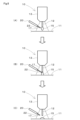
- the sliding member 30 includes a base material 11 and a sliding layer 32.
- the sliding member 30 slides on a mating member (not shown).
- the mating material is made of an Fe-based material such as steel or stainless steel.
- the sliding layer 32 forms a sliding surface 33 on the opposite side to the base material 11 .
- the base material 11 is made of metal such as Fe or Cu, or an alloy thereof.
- the sliding layer 32 is formed on the surface of this base material 11 by welding. Specifically, the sliding layer 32 is formed using the wire 12 as a main material by welding the wire 12 to the base material 11 as shown in FIG.
- the sliding layer 32 is an alloy whose first component is one of Cu, Al, and Sn. That is, the alloy matrix constituting the sliding layer 32 is formed by the wires 12.
- the first component is the one with the highest content among the alloys forming the sliding layer 32.
- the wire 12 is made of the same Cu alloy as the sliding layer 32.
- the sliding layer 32 has a particle phase 35 uniformly and finely dispersed in a matrix 34, as shown in FIG. That is, the sliding layer 32 has a matrix 34 and a particle phase 35 uniformly and finely dispersed in the matrix 34.
- the particle phase 35 includes a high hardness phase.
- the high hardness phase is a phase of particles that are harder than the matrix 34.
- the high hardness phase includes at least one element selected from, for example, Ni, Sn, Mo, C, B, Si, Mn, Fe, P, Ti, Al, W, Cr, Sc, Zr, Co, Cu, etc. or a compound, or a compound of these with O, N, etc.
- the Vickers hardness of the high hardness phase constituting the particle phase 35 is HV1
- the Vickers hardness of the matrix 34 is HV2
- the relationship between them is 5 ⁇ HV1/HV2 ⁇ 50. That is, the high hardness phase constituting the particle phase 35 has a Vickers hardness HV of 5 to 50 times that of the matrix 34.
- the particle phase 35 may include a low hardness phase.
- the low hardness phase is a phase of particles whose hardness is lower than that of the matrix 34.
- the low hardness phase is, for example, at least one element selected from Pb, Bi, Sn, Sb, In, Mg, Al, Zn, etc., or a compound thereof.
- the area ratio Sv of the particle phase 35 satisfies 0.2% ⁇ Sv ⁇ 5% in a plurality of observation regions set in an arbitrary observation cross section.
- the particle phase 35 is uniformly dispersed in the matrix 34 of the sliding layer 32. Further, the maximum particle diameter Da of the particle phase 35 is refined to 0 ⁇ m ⁇ Da ⁇ 30 ⁇ m.
- the particle phase 35 is uniformly and finely dispersed in the sliding layer 32, and the sliding characteristics can be improved without impairing the strength of the sliding layer 32.
- seizure resistance and wear resistance can be improved.
- a low hardness phase may exist together with a high hardness phase.
- the high hardness phase and the low hardness phase may exist uniformly and finely in the matrix 34 of the sliding layer 32.
- a structure may be adopted in which the high hardness phase is uniformly and finely present in the matrix 34 of the sliding layer 32, while the low hardness phase is not necessarily uniformly and finely dispersed in the matrix 34.
- the amount of the low hardness phase added in the sliding layer 32 is preferably 20 mass% or less.
- the sliding layer 32 may contain a solid lubricant regardless of hardness.
- the solid lubricant is, for example, at least one selected from graphite, MoS2 , and the like.
- the particle phase 35 is a general term including a high hardness phase and a low hardness phase.
- the wire 12 is supplied to the wire supply section 13 of the welding apparatus 10 shown in FIGS. 1 and 2.
- the wire 12 supplied to the wire supply section 13 is melted by arc discharge between the wire 12 and the base material 11, and forms a droplet 15 as shown in FIGS. 5(A) and 6(A).
- Additive material 21 is added to the formed droplet 15 .
- Additive material 21 is added to droplet 15 from additive material supply section 20 .
- the additive 21 is added to the droplet 15 from the additive supply unit 20 in the form of particles of a preselected material to become a particle phase 35, or a powder containing particles of the material, as shown in FIG. 5(A). Further, the additive 21 is added to the droplet 15 from the additive supply unit 20 in the form of a wire 22 containing particles of the material or a rod containing particles of the material, as shown in FIG. 6(A).
- the particle phase 35 containing at least one of a low hardness phase and a high hardness phase is formed from the additive 21 supplied from the additive supply unit 20. That is, by adding the additive material 21 to the droplets 15 of the molten wire 12, various materials that will become the particle phase 35 are mixed with the droplets 15 of the molten wire 12. Then, as shown in FIGS. 5(B) and 6(B), when the droplet 15 moves to the base material 11, the droplet 15 using the wire 12 as the material of the matrix 34 is stacked on the base material 11. As shown in FIGS. 5(C) and 6(C), the sliding layer 32 is formed on the base material 11 by solidifying the droplet 15.
- the sliding layer 32 is not limited to the above example, and may be formed as shown in FIG. 7.
- the wire 12 supplied to the wire supply section 13 is melted by arc discharge between it and the base material 11, and forms a droplet 15 as shown in FIG. 7(A).
- the formed droplet 15 moves to the base material 11 as shown in FIG. 7(B).
- the additive supply unit 20 adds the additive 21 to the droplet 15 that has transferred to the base material 11 and is in a molten state, as shown in FIG. 7(C). By adding the additive 21 to the molten droplet 15, various materials that will become the particle phase 35 are mixed into the molten droplet 15 of the wire 12.
- a sliding layer 32 is formed on the base material 11.
- the timing at which the additive supply unit 20 adds the additive 21 can be set between when the droplet 15 is formed by the arc and until it solidifies in the base material 11. can.
- These sliding layers 32 include the particle phase 35 made from the additive material 21 in the matrix 34 as described above.
- the additive material 21 is not a molten pool formed on the base material 11 by an arc between the base material 11 and the wire 12 when forming the sliding layer 32, but a droplet formed on the wire 12. Added to 15.
- the additive material 21 that becomes the particle phase 35 is uniformly and finely dispersed in the droplet 15, and is also uniformly and finely dispersed in the sliding layer 32 to be formed.
- the droplets 15 are quickly cooled down as they fall onto the base material 11. That is, the additive 21 added to the droplet 15 is uniformly and finely mixed with the droplet 15 having a relatively small volume, and then falls onto the base material 11 and is cooled, so that the additive material 21 is uniformly and finely mixed. solidifies while maintaining the
- the molten pool is a state in which the wire 12 and the base material 11 are mixed and melted. Therefore, for example, when the additive 21 is added to the molten pool, the additive 21 is mixed not only with the wire 12 that becomes the sliding layer 32 but also with the molten base material 11. Then, the base material 11, wire 12, and additive material 21 mixed in the molten pool have a slow solidification rate, and the additive material 21 tends to aggregate. Further, for example, if the additive 21 is mixed in advance with the wire 12, the temperature will rise during heating by arc, which will easily cause defects due to evaporation of the additive 21.
- the additive material 21 is added to the droplet 15, which has a relatively small heat capacity. Therefore, the particle phase 35 formed by the additive 21 can be rapidly cooled while remaining dispersed in the matrix 34 of the sliding layer 32. Further, in this embodiment, the occurrence of defects due to evaporation of the additive material 21 can be reduced.
- the thickness T of the sliding layer 32 formed on the base material 11 by welding is set to 0 mm ⁇ T ⁇ 0.5 mm by, for example, machining such as cutting or polishing.
- the sliding layer 32 is not required to have tensile strength as compared to, for example, a case where a bush or the like is used. Therefore, the thickness T of the sliding layer 32 can be reduced to 0.5 mm or less.
- the sliding member 30 includes a base material 11 and a sliding layer 32, as shown in FIGS. 3 and 4.
- a particle phase 35 made of the additive 21 is uniformly and finely dispersed in the matrix 34.
- Metals with low melting points, such as Pb and Bi, included in the low hardness phase of the particle phase 35 form a Pb phase and a Bi phase that are softer than the matrix 34 of the sliding layer 32. Therefore, the low hardness phase of the particle phase 35 increases the ability to embed foreign matter in the sliding portion when the sliding member 30 and the mating material slide, contributing to improving the seizure resistance.
- the high hardness phase of the particle phase 35 removes adhered substances generated when the sliding member 30 and the mating material slide.
- a sliding layer 32 was formed on a steel plate serving as a base material 11 by arc welding using a Cu alloy wire 12 using a welding apparatus 10 shown in FIG. 1 .
- a powdered additive 21 was supplied to the droplet 15 of the wire 12.
- the wire 12 is a Cu-Si-Mn alloy containing Cu as a main component, and forms the sliding layer 32 of a Cu-based alloy.
- the powder of additive material 21 Cu-22Pb-1.5Sn (mass%) was used.
- Ar containing 2 vol% O 2 was used.
- the voltage applied between the base material 11 and the wire 12 was set to 14V, and the welding current was set to 85A.
- a structure in which Pb as a particle phase 35 was uniformly and finely dispersed was formed in the sliding layer 32.
- the Pb phase was very fine, with a diameter of 0.5 to 3 ⁇ m in any cross section.
- the additive material 21 is added to the droplet 15 formed by melting the wire 12.
- the particle phase 35 made of the additive 21 is uniformly and finely dispersed in the matrix 34 of the sliding layer 32 to be formed. Therefore, by selecting the additive 21 while further enhancing the sliding performance, it is possible to appropriately control the sliding performance depending on the application.
- the sliding member 30 formed in this embodiment can be suitably used for a rotating member 40 that is large-scale and has high surface pressure, such as a shaft or a bearing for wind power generation, for example.
- the rotating member 40 includes a base material 11 and a sliding layer 32.
- the rotating member 40 includes a rotating shaft portion 41 and a sliding layer 32.
- the sliding layer 32 is directly provided on the rotating shaft portion 41 made of the base material 11 by welding. That is, in the rotating member 40, the sliding layer 32 is laminated on the outer peripheral side of the rotating shaft portion 41, which is a shaft member serving as the base material 11.
- the rotating shaft portion 41 and the sliding layer 32 constitute the sliding member 30. In this way, by directly providing the sliding layer 32 on the rotating shaft portion 41 by welding, the sliding member 30 equipped with the sliding layer 32 with controlled sliding performance can cope with high surface pressure. .
- the sliding layer 32 includes the matrix 34 and the particle phase 35 as described above.
- the area ratio Sv of the particle phase 35 is 0.2% ⁇ Sv ⁇ 5%.
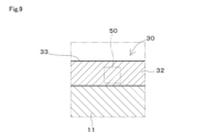
- an arbitrary observation cross section 50 is set as shown in FIG.
- the observation cross section 50 can be arbitrarily set in the sliding layer 32, such as in the thickness direction as shown in FIG. 9, for example.
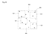
- An observation cross section 50 arbitrarily set on the sliding layer 32 includes a matrix 34 and a particle phase 35, as shown in FIG.
- Observation area 51 is extracted from this observation cross section 50.
- a plurality of observation regions 51 are extracted at arbitrary positions in the observation cross section 50 .
- the observation area 51 is extracted from the observation cross section 50 as an area having a size of 500 ⁇ m ⁇ 500 ⁇ m or more. If the observation area 51 is too small, the particle phase 35 may not be included in the observation area 51. That is, the observation area 51 needs to be large enough to include the particle phase 35.
- the observation area 51 can be set to any size within the above-mentioned range of 500 ⁇ m ⁇ 500 ⁇ m or more.
- the area ratio Sv of the particle phase 35 in this observation region 51 is 0.2% ⁇ Sv ⁇ 5%.
- the area ratio Sv is 0.2% ⁇ Sv ⁇ 5% in any of the plurality of arbitrary observation regions 51 extracted from the observation cross section 50. That is, the particle phase 35 has an area ratio Sv of 0.2% ⁇ Sv ⁇ 5% in any observation region 51. This indicates that the particle phase 35 is uniformly dispersed in the matrix 34 of the sliding layer 32. Further, the maximum particle diameter Da of the particle phase 35 is 0 ⁇ m ⁇ Da ⁇ 30 ⁇ m.
- the maximum particle diameter Da may be observed in the observation cross section 50 or may be observed in the observation area 51.
- the maximum particle diameter Da of the particle phase 35 contained in the sliding layer 32 is 0 ⁇ m ⁇ Da ⁇ 30 ⁇ m. This shows that the particle phase 35 dispersed in the matrix 34 of the sliding layer 32 is fine with a maximum particle size Da of 30 ⁇ m or less.
- the volume ratio W of the particle phase 35 contained in the sliding layer 32 is 0.1 vol% ⁇ W ⁇ 5.0 vol%.
- the volume ratio W is the sum of the volume of the particle phase 35 to the volume of the sliding layer 32.
- This volume ratio W is more preferably 0.2 vol% ⁇ W ⁇ 2.0 vol%.
- the high hardness phase among the particle phases 35 further contributes to improving the seizure resistance when the volume ratio W is 0.1 vol% or more.
- the upper limit of the volume ratio W is 5.0 vol%.
- the adhesive strength F between the base material 11 and the sliding layer 32 is preferably 250 N/mm 2 ⁇ F. In this manner, by ensuring the adhesive strength F, even if the rotating shaft portion 41 serving as the base material 11 is bent, peeling of the sliding layer 32 from the base material 11 can be reliably avoided. Furthermore, when forming the sliding layer 32, the depth Tt at which the base material 11 is affected by heat from the sliding layer 32 in the thickness direction is preferably Tt ⁇ 500 ⁇ m. By appropriately ensuring the temperature of the base metal 11 during welding, the range in which the base metal 11 is affected by heat due to welding is reduced. Therefore, the influence on the strength of the base material 11 is reduced.
- the time during which the base material 11 is heated is extremely short, and the influence of heat on the base material 11 is reduced. Therefore, changes in the structure of the base material 11 due to heat and the resulting influence on the strength of the base material 11 can be reduced.
- the roughness Ra on the surface of the sliding layer 32 satisfies Ra ⁇ 0.6.
- the roughness Ra of the surface of the sliding layer 32 is preferably 0.3 ⁇ Ra ⁇ 0.6. In this way, by setting the roughness Ra on the surface of the sliding layer 32, it is possible to reduce the friction coefficient of the sliding layer 32, reduce the number of processing steps and processing accuracy, and reduce the processing accuracy. It is possible to simplify the equipment associated with this.
- the test piece was obtained by overlaying a sliding layer 32 on a Fe-based base material 11 using a wire 12 and an additive 21.
- the sliding layer 32 was formed by MIG welding using a CMT method in which the wire 12 is repeatedly fed at high speed in the forward and reverse directions into a molten pool generated during welding. After welding, the specimen was machined into a predetermined shape by cutting and polishing.
- the adhesive strength was evaluated as the strength of the sliding member 30.
- the adhesive strength is the adhesive force between the base material 11 and the sliding layer 32.
- a test piece 60 in which the base material 11 and the sliding layer 32 were bonded with a predetermined bonding area as shown in FIGS. 11 and 12 was used.
- the adhesive strength was measured by applying a tensile load to both ends of the test piece 60 and measuring the maximum tensile force at which the joint 61 breaks.
- the test piece 60 used had an overlap of 9 mm x 0.3 mm at the joint 61 between the base material 11 and the sliding layer 32, and a joint area of 2.7 mm2 .
- the test piece 60 has a width of 9 mm and a length of the overlapping portion of 0.3 mm.
- the adhesion test was carried out by applying a load of 2 kN outward to both ends of the test piece 60 at a speed of 5 m/min.
- the strength and sliding characteristics of the sliding member 30 were evaluated for seizure resistance by a seizure test and abrasion resistance by an abrasion test.
- seizure test the maximum surface pressure of the sliding member 30 without seizure was evaluated as the seizure resistance.
- wear test the amount of wear of the sliding member 30 was evaluated as wear resistance.
- seizure test and wear test in the sliding test a test piece 70 formed in an arcuate ring shape is attached to a holder 71 as shown in FIGS. 13 and 14, and the test piece 70 attached to the holder 71 is attached to a cylindrical test shaft. It was carried out under pressure of 72.
- the examples and comparative examples of the sliding member 30 were evaluated by a seizure test under the conditions shown in FIG. 15 and an abrasion test under the conditions shown in FIG. 16.
- the evaluation results of Examples and Comparative Examples are shown in FIG. 17 and FIG. 18, respectively.
- the area ratio Sv of the particle phase 35 is determined by arbitrarily extracting ten observation areas 51 from an arbitrary observation cross section 50, and calculating the maximum and minimum values of the area ratio Sv in each extracted observation area 51. That is, in the case of FIG. 17 and FIG. 18, the area ratio Sv is the maximum value and minimum value of the ten observation areas 51.
- the maximum particle diameter Da of the particle phase 35 is the particle diameter of the particle phase 35 that is the largest among the particle phases 35 in the ten observation regions 51 extracted from the observation cross section 50.
- the observation area 51 was set to 500 ⁇ m ⁇ 500 ⁇ m.
- the area ratio Sv of the particle phase 35 is excessive. Therefore, it can be seen that these Samples 10, 13, and 16 have a reduced amount of wear, but are highly aggressive toward the mating material, leading to a decrease in seizure resistance.
- Sample 11, Sample 14, and Sample 17, which are comparative examples the particle phase 35 is aggregated, and the maximum particle diameter Da is excessive. Due to the agglomeration of the particle phase 35, the sliding layer 32 has different seizure resistance and wear resistance depending on the location. Therefore, it can be seen that in these samples 11, 14, and 17, the distribution of the particle phase 35 in the matrix 34 becomes uneven, and the seizure resistance and wear resistance deteriorate.
- samples 12, 15, and 18, which are comparative examples the area ratio Sv of the particle phase 35 contained in the sliding layer 32 is too small. Therefore, it can be seen that these samples 12, 15, and 18 cannot be expected to improve in seizure resistance and wear resistance.
- Sample 19 and Sample 20 which are comparative examples, the additive 21 is added to the molten pool formed in the base material 11. Therefore, samples 19 and 20 suffer from segregation in which the particle phase 35 is locally generated. It can be seen that sample 19 and sample 20 have increased variations in seizure resistance and wear resistance due to this segregation.
- Sample 21 and Sample 22, which are comparative examples the additive 21 was not added, and the sliding layer 32 did not contain the particle phase 35. Therefore, it can be seen that Sample 21 and Sample 22 have deteriorated seizure resistance and wear resistance.
- the sliding member 30 may include an overlay layer (not shown) in addition to the base material 11 and the sliding layer 32.
- the overlay layer is formed on the surface of the sliding layer 32, that is, the surface opposite to the base material 11, so as to overlap the sliding layer 32.
- the overlay layer is preferably made of a soft metal or alloy such as Sn or Bi.
- the overlay layer may be made of, for example, a resin in which a solid lubricant is dispersed.
- the sliding member 30 may include one or more intermediate layers (not shown) between the base material 11 and the sliding layer 32.
- a material that increases the adhesive force between the base material 11 and the sliding layer 32 such as Ni or an alloy thereof, for the intermediate phase.
Abstract
摺動部材は、母材と、前記母材に積層され、マトリクスおよび前記マトリクスに均一かつ微細に分散した粒子相を有する摺動層と、を備える。前記摺動層において任意の観察断面を設定し、前記観察断面から抽出した複数の任意の観察領域における前記粒子相の面積率Svは、いずれの前記観察領域においても、0.2%≦Sv≦5%である。前記粒子相の最大粒子径Daは、0μm<Da≦30μmである。
Description
本出願は、2022年3月30日に出願された日本出願2022-056211号に基づくものであり、ここにその記載内容を援用する。
本開示は、摺動部材、およびこれを用いたギアボックス、風力発電機、ならびに摺動部材の製造方法に関する。
従来、アーク溶接によって摺動部材を形成することが周知である(特許文献1)。特許文献1では、裏金の表面にアーク溶接によってCu-Sn-Pbの合金を摺動層として積層している。このとき、摺動層は、合金のマトリクスにPbが予め分散された粉末を用いて形成される。これにより、特許文献1では、溶接時の高温によるPbの蒸発を低減し、摺動層にPbが均一に分散した組織の形成を図っている。
近年、環境へ与える負荷のさらなる低減などの要求から、摺動部材を用いる軸受は、高い面圧環境における摺動特性の向上が求められている。そこで、マトリクスに例えば低融点の金属や硬質の材料などを添加材として添加し、摺動層の性質の向上が図られている。この場合、摺動層は、例えばあらかじめマトリクスに添加材を加えた粉末やワイヤを用いて溶接を行なうことにより形成することができる。
ところが、マトリクスに添加された低融点の金属は、溶接時に蒸発を招きやすく、摺動層のマトリクスの欠陥や偏析を招くという問題がある。また、マトリクスに添加された硬質の材料は、溶接時に凝集を招きやすく、マトリクスにおける均一な分散が困難であるという問題がある。摺動層における硬質粒子の偏在は、摺動層の強度の低下および摺動特性の悪化を招くという問題がある。
そこで、本開示の目的は、摺動層に添加物の粒子が均一に分散し、強度を損なうことなく、摺動特性が高い摺動部材、およびこれを用いたギアボックス、風力発電機を提供することにある。
また、本開示の他の目的は、添加物の蒸発を低減し、添加物の均一な分散を図り、摺動特性のさらなる向上が図られる摺動部材の製造方法を提供することにある。
また、本開示の他の目的は、添加物の蒸発を低減し、添加物の均一な分散を図り、摺動特性のさらなる向上が図られる摺動部材の製造方法を提供することにある。
本開示の一実施形態による摺動部材は、母材と、前記母材に積層され、マトリクスおよび前記マトリクスに均一かつ微細に分散した粒子相を有する摺動層と、を備える摺動部材である。
すなわち、一実施形態の摺動部材は、任意の観察断面から抽出した複数の任意の観察領域において、粒子相の面積率Svがいずれも0.2%≦Sv≦5%である。このように、一実施形態の摺動部材は、摺動層のマトリクスに粒子相が均一に存在する。そして、粒子相の最大粒子径Daは、0μm<Da≦30μmと微細化されている。したがって、摺動層に添加物の粒子が均一かつ微細に分散し、強度を損なうことなく、摺動特性を高めることができる。特に、一実施形態の摺動部材は、耐焼付性および耐摩耗性を高めることができる。
すなわち、一実施形態の摺動部材は、任意の観察断面から抽出した複数の任意の観察領域において、粒子相の面積率Svがいずれも0.2%≦Sv≦5%である。このように、一実施形態の摺動部材は、摺動層のマトリクスに粒子相が均一に存在する。そして、粒子相の最大粒子径Daは、0μm<Da≦30μmと微細化されている。したがって、摺動層に添加物の粒子が均一かつ微細に分散し、強度を損なうことなく、摺動特性を高めることができる。特に、一実施形態の摺動部材は、耐焼付性および耐摩耗性を高めることができる。
本開示の一実施形態による摺動部材の製造方法は、母材にワイヤをアーク溶接することによって摺動層を形成する。この摺動部材の製造方法は、前記摺動層を構成するマトリクスとなる前記ワイヤを供給する工程と、供給された前記ワイヤを、前記母材との放電によって溶融し、溶滴を形成する工程と、形成された溶滴に、前記マトリクスに添加する添加材を添加する工程と、を含む。
これにより、添加材は、溶融したワイヤの溶滴に混合される。すなわち、本実施形態では、添加材は、母材とワイヤとのアークによって母材に形成される溶融池ではなく、ワイヤに形成される溶滴に加えられる。そのため、添加材は、溶滴に均一かつ微細に分散し、溶滴が凝固して形成される摺動層にも均一かつ微細に分散する。これは、溶滴が母材に落下することにより、溶滴は迅速に冷却されるからである。すなわち、溶滴に加えられた添加材は、容積が比較的小さな溶滴と均一かつ微細に混合された後、母材に落下して冷却され、均一かつ微細に混合された状態を維持したまま凝固する。また、溶滴に添加材を加えることにより、溶融池に添加材を加える場合と比較して、母材と添加材との混合が低減される。さらに、本実施形態のように比較的熱容量が小さい溶滴に添加材を加えることにより、添加材が溶滴に分散した状態のまま迅速に冷却され、添加材の蒸発にともなう欠陥も低減される。したがって、摺動性能のさらなる向上を図ることができる。
他の実施形態による摺動部材の製造方法では、前記マトリクスに添加される前記添加材は、粒子、前記粒子を含む粉末、前記粒子を含むワイヤ、または前記粒子を含む棒材として前記溶滴に加えられる。
以下、図面に基づいて実施形態を説明する。
(溶接装置)
まず、摺動部材を製造するための溶接装置について説明する。
図1に示すように溶接装置10は、母材11とワイヤ12との間の放電を用いた、いわゆるアーク溶接装置である。溶接装置10は、ワイヤ供給部13を備えている。ワイヤ供給部13は、消耗電極であるワイヤ12を、予め設定された周期と移動量で周期的に母材11側へ移動とその反対側への移動とを繰り返しつつ供給する。ワイヤ供給部13と母材11との間は、電源装置14を通して電気的に接続されている。電源装置14は、ワイヤ供給部13と母材11との間に予め設定された電圧を印加する。ワイヤ12は、ワイヤ供給部13に接することによって、ワイヤ供給部13と同一の電位となる。これにより、母材11とワイヤ12とが接近するとアーク状態になるとともに、母材11とワイヤ12とが接すると短絡状態となる。ワイヤ供給部13によりワイヤ12を進退することにより、母材11とワイヤ12との間はアーク状態と短絡状態とが繰り返し発生する。
ワイヤ供給部13によってワイヤ12の先端が母材11に接近すると、ワイヤ12と母材11との間にアークが発生する。ワイヤ12は、発生したアークによって瞬時に加熱され、溶融する。溶融したワイヤ12は、溶滴15となって母材11側へ落下する。溶融したワイヤ12の溶滴15が母材11に接すると、母材11とワイヤ12とが短絡し母材11とワイヤ12との間の通電が停止され、溶滴15は母材11に移行する。すなわち、ワイヤ12は、アーク溶接による溶滴移行によって母材11に積層される。ワイヤ供給部13がワイヤ12の先端を母材11から遠ざけることによって、母材11とワイヤ12とが離間し、再び母材11とワイヤ12との間にアークが発生する。これを繰り返すことにより、母材11にはワイヤ12を構成する材料によって溶接層が形成される。
ワイヤ供給部13は、ガス噴出口16を有している。ワイヤ供給部13は、ガス噴出口16からシールドガス17を噴射する。シールドガス17は、例えばアルゴンやヘリウムなどの不活性ガスを主成分とし、酸素などが添加されている。ガス噴出口16は、母材11とワイヤ12とが接触する溶接部の近傍を包囲するようにシールドガス17を噴射する。これにより、母材11とワイヤ12との溶接部は、シールドガス17によって外気から遮蔽される。シールドガス17は、O2を含むAr、100%のAr、CO2、Ar+CO2、Ar+Heなどを用いることができる。
溶接装置10は、上記に加え、添加材供給部20を備えている。添加材供給部20は、母材11とワイヤ12との間のアークによって形成された溶滴15に添加材21を供給する。本実施形態では、添加材供給部20は、母材11とワイヤ12との間のアークによって母材11側に形成された溶融池ではなく、ワイヤ12側に形成された溶滴15に添加材21を供給する。添加材供給部20は、図1に示すように粉末状の添加材21を溶滴15に供給する。また、添加材供給部20は、図2に示すように添加材21を含むワイヤ22を溶滴15に供給する構成でもよい。さらに、添加材供給部20は、これら図1および図2に示す例に限らず添加材21を含む棒材などを溶滴15に供給する構成でもよい。
以上のように、本実施形態の場合、溶接装置10は、添加材供給部20を備えている。そのため、添加材21は、母材11とワイヤ12との間のアークによってワイヤ12が溶融して形成される溶滴15に供給される。
(摺動部材の製造方法、摺動部材)
次に、上記の溶接装置を用いた摺動部材の製造方法、およびこれにより得られる摺動部材について説明する。
図3に示すように摺動部材30は、母材11および摺動層32を備えている。摺動部材30は、図示しない相手材と摺動する。相手材は、例えば鋼やステンレスなどのFe系の材料で形成されている。摺動層32は、母材11と反対側の面に摺動面33を形成する。母材11は、例えばFeやCuなどの金属またはこれらの合金で形成されている。摺動層32は、この母材11の表面に溶接によって形成されている。具体的には、摺動層32は、図1に示すようにワイヤ12を母材11に溶接することによってワイヤ12を主材料として形成されている。摺動層32は、Cu、Al、Snのうちの元素を第一成分とする合金である。すなわち、摺動層32を構成する合金のマトリクスは、ワイヤ12によって形成される。第一成分とは、摺動層32を構成する合金の中で最も含有率の高いものである。例えば摺動層32をCu合金で形成する場合、ワイヤ12はこの摺動層32と同一のCu合金で形成されている。
摺動層32は、図4に示すようにマトリクス34に均一かつ微細に分散した粒子相35を有している。すなわち、摺動層32は、マトリクス34と、このマトリクス34に均一かつ微細に分散した粒子相35とを有している。粒子相35は、高硬度相を含んでいる。高硬度相は、マトリクス34よりも硬度の高い粒子の相である。高硬度相は、例えばNi、Sn、Mo、C、B、Si、Mn、Fe、P、Ti、Al、W、Cr、Sc、Zr、Co、Cuなどから選択される少なくとも1つ以上の元素もしくは化合物、またはこれらとO、Nなどとの化合物である。
粒子相35を構成する高硬度相のビッカース硬度をHV1とし、マトリクス34のビッカース硬度をHV2としたとき、これらの間には、5≦HV1/HV2≦50の関係となる。つまり、粒子相35を構成する高硬度相は、マトリクス34よりもビッカース硬度HVが5倍から50倍である。このように、マトリクス34に対する高硬度相の硬さを設定することにより、耐焼付性および耐摩耗性を向上させつつ、相手材への攻撃性を低減することができる。
また、粒子相35は、低硬度相を含んでいてもよい。低硬度相は、マトリクス34よりも硬度の低い粒子の相である。低硬度相は、例えばPb、Bi、Sn、Sb、In、Mg、Al、Znなどから選択される少なくとも1つ以上の元素、またはこれらの化合物である。この場合、任意の観察断面に設定した複数の観察領域において、粒子相35の面積率Svは、0.2%≦Sv≦5%である。粒子相35は、摺動層32のマトリクス34に均一に分散している。そして、粒子相35の最大粒子径Daは、0μm<Da≦30μmと微細化されている。したがって、粒子相35が摺動層32に均一かつ微細に分散し、摺動層32の強度を損なうことなく、摺動特性を高めることができる。特に、摺動層32の摺動特性として、耐焼付性および耐摩耗性を高めることができる。
また、粒子相35のうち低硬度相は、高硬度相とともに存在してもよい。この場合、高硬度相および低硬度相は、摺動層32のマトリクス34に均一かつ微細に存在してもよい。さらに、高硬度相が摺動層32のマトリクス34に均一かつ微細に存在する構成としつつ、低硬度相は必ずしもマトリクス34に均一かつ微細に分散しない構成としてもよい。このように低硬度相がマトリクス34に均一かつ微細に分散していない場合、摺動層32における低硬度相の添加量は、20mass%以下であることが好ましい。このように、低硬度相の添加量を20mass%以下にすることにより、摺動層32の強度への影響が低減される。さらに、摺動層32は、硬度に関係なく、固体潤滑剤を含んでいてもよい。固体潤滑剤は、例えばグラファイト、MoS2などから選択される少なくとも1種以上である。以下、粒子相35とは、高硬度相および低硬度相を含む総称である。
ワイヤ12は、図1および図2に示す溶接装置10のワイヤ供給部13に供給される。ワイヤ供給部13に供給されたワイヤ12は、母材11との間のアーク放電によって溶融し、図5(A)および図6(A)に示すように溶滴15を形成する。形成された溶滴15は、添加材21が添加される。添加材21は、添加材供給部20から溶滴15に添加される。添加材21は、図5(A)に示すように粒子相35となる予め選択された材料の粒子、材料の粒子を含む粉末として添加材供給部20から溶滴15に添加される。また、添加材21は、図6(A)に示すように材料の粒子を含むワイヤ22、または材料の粒子を含む棒材として添加材供給部20から溶滴15に添加される。
低硬度相および高硬度相のうち少なくともいずれか一方を含む粒子相35は、添加材供給部20から供給される添加材21から形成される。すなわち、溶融したワイヤ12の溶滴15に添加材21を添加することにより、溶融したワイヤ12の溶滴15に粒子相35となる各種の材料が混合される。そして、図5(B)および図6(B)に示すように溶滴15が母材11へ移行すると、ワイヤ12をマトリクス34の材料とする溶滴15は母材11に積層される。図5(C)および図6(C)に示すように溶滴15が凝固することにより、母材11には摺動層32が形成される。
摺動層32は、上記の例に限らず、図7に示すように形成してもよい。図7に示す例の場合、ワイヤ供給部13に供給されたワイヤ12は、母材11との間のアーク放電によって溶融し、図7(A)に示すように溶滴15を形成する。形成された溶滴15は、図7(B)に示すように母材11へ移行する。図7に示す例の場合、添加材供給部20は、図7(C)に示すように母材11へ移行して溶融状態となっている溶滴15に添加材21を添加する。溶融した溶滴15に添加材21を添加することにより、溶融したワイヤ12の溶滴15に粒子相35となる各種の材料が混合される。そして、溶滴15が凝固することにより、母材11には摺動層32が形成される。なお、図5または図7に示すように、添加材供給部20が添加材21を添加する時期は、アークによって溶滴15が形成されて母材11で凝固するまでの間に設定することができる。
これらの摺動層32は、上述のようにマトリクス34に添加材21を原料とする粒子相35を含んでいる。本実施形態の場合、添加材21は、摺動層32の形成時において、母材11とワイヤ12とのアークによって母材11に形成される溶融池ではなく、ワイヤ12に形成される溶滴15に加えられる。これにより、粒子相35となる添加材21は、溶滴15に均一かつ微細に分散し、形成される摺動層32にも均一かつ微細に分散する。これは、溶滴15が母材11に落下することにより、溶滴15は迅速に冷却されるからである。すなわち、溶滴15に加えられた添加材21は、容積が比較的小さな溶滴15と均一かつ微細に混合された後、母材11に落下して冷却され、均一かつ微細に混合された状態を維持したまま凝固する。
また、溶滴15に添加材21を加えることにより、溶融池に添加材21を加える場合と比較して、摺動層32において母材11との混合は低減される。溶融池は、ワイヤ12と母材11とが混合して溶融した状態となっている。そのため、例えば溶融池に添加材21を加えると、添加材21は摺動層32となるワイヤ12だけでなく溶融した母材11とも混合される。そして、溶融池で混合された母材11、ワイヤ12および添加材21は、凝固速度が緩やかとなり、添加材21の凝集を招きやすくなる。さらに、例えば予めワイヤ12に添加材21を混合すると、アークによる加熱時に温度が上昇し、添加材21の蒸発などによる欠陥を招きやすくなる。
これらに対し、本実施形態では、添加材21は、比較的熱容量が小さい溶滴15に加えられる。そのため、添加材21による粒子相35は、摺動層32のマトリクス34に分散した状態のまま迅速に冷却することができる。また、本実施形態では、添加材21の蒸発にともなう欠陥の発生を低減することができる。
溶接によって母材11に形成された摺動層32は、例えば切削や研磨などの機械加工によって、厚さTが0mm<T≦0.5mmに設定される。このように、溶接によって摺動層32を形成することにより、摺動層32は例えばブッシュなどを用いる場合と比較して引張強度が要求されない。したがって、摺動層32の厚さTを0.5mm以下と薄くすることができる。
以上の手順により、母材11に摺動層32が積層された摺動部材30が製造される。
以上の手順により、母材11に摺動層32が積層された摺動部材30が製造される。
摺動部材30は、図3および図4に示すように母材11および摺動層32を備えている。本実施形態の場合、図4に示すようにマトリクス34に添加材21からなる粒子相35が均一かつ微細に分散している。粒子相35の低硬度相に含まれるPbやBiなどの融点の低い金属は、摺動層32のマトリクス34に比較して柔らかいPb相やBi相を形成する。そのため、粒子相35の低硬度相は、摺動部材30と相手材との摺動時における摺動部分での異物埋収性を高め、耐焼付性の向上に寄与する。一方、粒子相35の高硬度相は、摺動部材30と相手材との摺動時に生じる凝着物を除去する。摺動部材30と相手材との摺動部分に摺動によって生じた凝着物などの異物が相手材に付着すると、凝着物と摺動部材30の摺動面33とが接し、その部分で焼付を招くおそれがある。摺動層32に含まれる例えばMo2Cなどの高硬度相は、この摺動部分に付着する異物を掻き落す。これにより、粒子相35の高硬度相は、摺動部材30と相手部材との焼付の低減に寄与する。
(摺動部材の実施の一例)
摺動部材30の実施の一例を検証した。実施の一例は、図1に示す溶接装置10を用いて、母材11となる鋼板に、Cu合金のワイヤ12を用いてアーク溶接によって摺動層32を形成した。母材11にワイヤ12を溶接するとき、粉末状の添加材21をワイヤ12の溶滴15に供給した。ワイヤ12は、Cu-Si-MnのCuを主成分とする合金であり、Cu系合金の摺動層32を形成する。添加材21の粉末は、Cu-22Pb-1.5Sn(質量%)を用いた。シールドガス17は、2vol%のO2を含むArを用いた。母材11とワイヤ12との間に印加する電圧は14Vに設定し、溶接電流は85Aに設定した。その結果、図4に示すように摺動層32に粒子相35としてのPbが均一かつ微細に分散した組織が形成された。Pb相は、非常に微細であり、任意の断面における直径が0.5~3μmであった。
摺動部材30の実施の一例を検証した。実施の一例は、図1に示す溶接装置10を用いて、母材11となる鋼板に、Cu合金のワイヤ12を用いてアーク溶接によって摺動層32を形成した。母材11にワイヤ12を溶接するとき、粉末状の添加材21をワイヤ12の溶滴15に供給した。ワイヤ12は、Cu-Si-MnのCuを主成分とする合金であり、Cu系合金の摺動層32を形成する。添加材21の粉末は、Cu-22Pb-1.5Sn(質量%)を用いた。シールドガス17は、2vol%のO2を含むArを用いた。母材11とワイヤ12との間に印加する電圧は14Vに設定し、溶接電流は85Aに設定した。その結果、図4に示すように摺動層32に粒子相35としてのPbが均一かつ微細に分散した組織が形成された。Pb相は、非常に微細であり、任意の断面における直径が0.5~3μmであった。
以上説明したように、本実施形態では、ワイヤ12の溶融によって形成された溶滴15に添加材21を添加している。これにより、添加材21からなる粒子相35は形成される摺動層32のマトリクス34に均一かつ微細に分散する。したがって、摺動性能をより高めるとともに、添加材21を選択することにより、摺動性能を用途に応じて適切に制御することができる。
図8に示すように、本実施形態で形成する摺動部材30は、例えば風力発電の軸や軸受など、大規模かつ面圧が高い回転部材40に好適に用いることができる。図8に示す例の場合、回転部材40は、母材11および摺動層32を備えている。回転部材40は、回転軸部41および摺動層32を備えている。そして、回転部材40は、母材11からなる回転軸部41に、摺動層32が溶接によって直接設けられている。すなわち、回転部材40は、母材11となる軸部材である回転軸部41の外周側に摺動層32が積層されている。これら回転軸部41と摺動層32とは、摺動部材30を構成している。
このように、回転軸部41に溶接によって摺動層32を直接設けることにより、摺動性能が制御された摺動層32を備える摺動部材30によって、高い面圧にも対応することができる。
このように、回転軸部41に溶接によって摺動層32を直接設けることにより、摺動性能が制御された摺動層32を備える摺動部材30によって、高い面圧にも対応することができる。
次に、摺動層32について詳細に説明する。
摺動層32は、上述のようにマトリクス34と、粒子相35とを有している。粒子相35の面積率Svは、0.2%≦Sv≦5%である。具体的には、摺動層32は、図9に示すように任意の観察断面50が設定される。観察断面50は、例えば図9に示すように厚さ方向など、摺動層32において任意に設定することができる。摺動層32に任意に設定した観察断面50には、図10に示すようにマトリクス34および粒子相35が含まれている。観察領域51は、この観察断面50から抽出される。観察領域51は、観察断面50において、任意の位置で複数抽出される。この場合、観察領域51は、観察断面50から、500μm×500μm以上の大きさの領域として抽出される。観察領域51は、小さすぎると観察領域51に粒子相35が含まれない可能性がある。つまり、観察領域51は、粒子相35が含まれる程度に十分な大きさの範囲とする必要がある。観察領域51は、上述の500μm×500μm以上の範囲であれば任意の寸法に設定することができる。
摺動層32は、上述のようにマトリクス34と、粒子相35とを有している。粒子相35の面積率Svは、0.2%≦Sv≦5%である。具体的には、摺動層32は、図9に示すように任意の観察断面50が設定される。観察断面50は、例えば図9に示すように厚さ方向など、摺動層32において任意に設定することができる。摺動層32に任意に設定した観察断面50には、図10に示すようにマトリクス34および粒子相35が含まれている。観察領域51は、この観察断面50から抽出される。観察領域51は、観察断面50において、任意の位置で複数抽出される。この場合、観察領域51は、観察断面50から、500μm×500μm以上の大きさの領域として抽出される。観察領域51は、小さすぎると観察領域51に粒子相35が含まれない可能性がある。つまり、観察領域51は、粒子相35が含まれる程度に十分な大きさの範囲とする必要がある。観察領域51は、上述の500μm×500μm以上の範囲であれば任意の寸法に設定することができる。
この観察領域51における粒子相35の面積率Svは、0.2%≦Sv≦5%である。面積率Svとは、観察領域51の面積Sと、この観察領域51に含まれる粒子相35の面積の総和Smとから、Sv=Sm/S×100として算出される。本実施形態では、この面積率Svは、観察断面50から抽出した複数の任意の観察領域51のいずれにおいても、0.2%≦Sv≦5%である。つまり、粒子相35は、いずれの観察領域51においても面積率Svが0.2%≦Sv≦5%である。これは、粒子相35が摺動層32のマトリクス34に均一に分散していることを示している。また、粒子相35の最大粒子径Daは、0μm<Da≦30μmである。最大粒子径Daは、観察断面50において観察してもよく、観察領域51において観察してもよい。いずれにしても、摺動層32に含まれる粒子相35の最大粒子径Daは、0μm<Da≦30μmである。このように、摺動層32のマトリクス34に分散する粒子相35は、最大粒子径Daが30μm以下の微細なものであることを示している。
摺動層32に含まれる粒子相35の体積割合Wは、0.1vol%≦W≦5.0vol%であることが好ましい。体積割合Wは、摺動層32の体積に対する粒子相35の体積の総和である。この体積割合Wは、0.2vol%≦W≦2.0vol%であることがより好ましい。粒子相35のうち特に高硬度相は、体積割合Wが0.1vol%以上になると、耐焼付性の向上にさらに寄与する。また、体積割合Wは、上限を5.0vol%とすることが好ましい。体積割合Wを5.0vol%以下とすることにより、相手材への攻撃性は効果的に抑制される。
母材11と摺動層32との間の接着強度Fは、250N/mm2≦Fであることが好ましい。このように、接着強度Fを確保することにより、母材11となる回転軸部41にたわみが生じても、母材11からの摺動層32の剥離は確実に回避される。また、摺動層32の形成時において、厚さ方向において母材11が摺動層32から熱の影響を受ける深さTtは、Tt≦500μmであることが好ましい。溶接時における母材11の温度を適切に確保することにより、母材11が溶接による熱の影響を受ける範囲は低減される。そのため、母材11の強度への影響は減少する。すなわち、本実施形態の場合、母材11が加熱される時間は極めて短く、母材11への熱の影響が小さくなる。したがって、熱による母材11の組織の変化、およびこれにともなう母材11の強度への影響を小さくすることができる。
摺動層32の表面における粗さRaは、Ra≦0.6であることが好ましい。特に、摺動層32の表面における粗さRaは、0.3≦Ra≦0.6であることがより好ましい。このように、摺動層32の表面における粗さRaを設定することにより、摺動層32の摩擦係数の低減を図りつつ、加工工数および加工精度を低減することができるとともに、加工精度の低減にともなう設備の簡素化を図ることができる。
以下、摺動部材30の具体的な実施例および比較例について説明する。
実施例および比較例は、接着試験および摺動試験によって評価した。試験片は、Fe系の母材11に、ワイヤ12および添加材21で摺動層32を肉盛溶接した。摺動層32は、溶接時に生成した溶融池へ、ワイヤ12を正方向および逆方向へ高速で供給を繰り返すCMT式を用いて、MIG溶接によって形成した。溶接の後、試験片は、切削および研磨などの機械加工を加えて所定の形状とした。
実施例および比較例は、接着試験および摺動試験によって評価した。試験片は、Fe系の母材11に、ワイヤ12および添加材21で摺動層32を肉盛溶接した。摺動層32は、溶接時に生成した溶融池へ、ワイヤ12を正方向および逆方向へ高速で供給を繰り返すCMT式を用いて、MIG溶接によって形成した。溶接の後、試験片は、切削および研磨などの機械加工を加えて所定の形状とした。
接着試験では、摺動部材30の強度として、接着強度を評価した。接着強度は、母材11と摺動層32との接着力である。接着試験では、図11および図12に示すように母材11と摺動層32とが所定の接合面積で接合されている試験片60を用いた。接着強度は、試験片60の両端に引張荷重を加え、接合部61が破壊する最大の引張力を測定した。用いた試験片60は、母材11と摺動層32との接合部61において重なりが9mm×0.3mmであり、接合面積が2.7mm2である。つまり、試験片60は、幅が9mmであり、重なり部分の長さが0.3mmである。接着試験は、試験片60の両端に、外側へ向けて2kNの荷重を5m/minの速度で加えて実施した。
摺動試験では、摺動部材30の強度および摺動特性として、焼付試験による耐焼付性、および摩耗試験による耐摩耗性を評価した。焼付試験では、摺動部材30の焼き付かない最大面圧を耐焼付性として評価した。摩耗試験では、摺動部材30の摩耗量を耐摩耗性として評価した。摺動試験における焼付試験および摩耗試験は、図13および図14に示すように円弧環状に形成した試験片70を保持具71に取り付け、保持具71に取り付けた試験片70を筒状の試験軸72に押し付けて実施した。摺動試験は、図15に示す条件による焼付試験、および図16に示す条件による摩耗試験で摺動部材30の実施例および比較例を評価した。
実施例および比較例の評価結果をそれぞれ図17および図18に示す。粒子相35の面積率Svは、任意の観察断面50から10箇所の観察領域51を任意に抽出し、抽出した各観察領域51における面積率Svの最大値および最小値を算出している。すなわち、図17および図18の場合、面積率Svは、10箇所の観察領域51の最大値および最小値である。粒子相35の最大粒子径Daは、観察断面50から抽出した10箇所の観察領域51における粒子相35のうち最大となる粒子相35の粒子径である。観察領域51は、500μm×500μmに設定した。焼付試験では、焼き付かない最大面圧が18MPa以上を「適格」とした。摩耗試験では、摩耗量が5μm以下を「適格」とした。なお、焼付試験においては、試験機器の性能の制約から、25MPaが最大値である。
図17に示すように実施例である試料1~試料9は、いずれも接着強度、最大面圧および摩耗量が適格である。これに対し、図18に示すように比較例である試料10、試料13および試料16は、粒子相35の面積率Svが過大となっている。そのため、これら試料10、試料13および試料16は、摩耗量が低下するものの、相手材への攻撃性が高く、耐焼付性の低下を招くことがわかる。また、比較例である試料11、試料14および試料17は、粒子相35が凝集し、最大粒子径Daが過大となっている。粒子相35が凝集することにより、摺動層32は、場所によって耐焼付性および耐摩耗性が異なる。そのため、これら試料11、試料14および試料17は、マトリクス34における粒子相35の分布が不均一になり、耐焼付性および耐摩耗性が悪化することがわかる。
比較例である試料12、試料15および試料18は、摺動層32に含まれる粒子相35の面積率Svが過小となっている。そのため、これら、試料12、試料15および試料18は、耐焼付性および耐摩耗性の向上が見込めないことがわかる。比較例である試料19および試料20は、添加材21を母材11に生じた溶融池に添加している。そのため、試料19および試料20は、粒子相35が局所的に生成する偏析を招いている。試料19および試料20は、この偏析によって、耐焼付性および耐摩耗性のばらつきが増大していることがわかる。比較例である試料21および試料22は、添加材21を添加しておらず、摺動層32に粒子相35が含まれていない。そのため、試料21および試料22は、耐焼付性および耐摩耗性が悪化することがわかる。
以上説明した本発明は、上記実施形態に限定されるものではなく、その要旨を逸脱しない範囲で種々の実施形態に適用可能である。
例えば、摺動部材30は、母材11および摺動層32に加え、図示しないオーバレイ層を備えていてもよい。この場合、オーバレイ層は、摺動層32の表面、つまり母材11と反対側の面に摺動層32に重ねて形成される。オーバレイ層は、例えばSnやBiなどの軟質の金属または合金を用いることが好ましい。また、オーバレイ層は、例えば固体潤滑剤を分散した樹脂などを用いてもよい。摺動部材30は、オーバレイ層を備えるとき、このオーバレイ層の最表面が相手材と摺動する摺動面33となる。さらに、摺動部材30は、母材11と摺動層32との間に、図示しない1層以上の中間層を備えていてもよい。この場合、中間相は、例えばNiやその合金など、母材11と摺動層32との接着力を高める材料を用いることが好ましい。
例えば、摺動部材30は、母材11および摺動層32に加え、図示しないオーバレイ層を備えていてもよい。この場合、オーバレイ層は、摺動層32の表面、つまり母材11と反対側の面に摺動層32に重ねて形成される。オーバレイ層は、例えばSnやBiなどの軟質の金属または合金を用いることが好ましい。また、オーバレイ層は、例えば固体潤滑剤を分散した樹脂などを用いてもよい。摺動部材30は、オーバレイ層を備えるとき、このオーバレイ層の最表面が相手材と摺動する摺動面33となる。さらに、摺動部材30は、母材11と摺動層32との間に、図示しない1層以上の中間層を備えていてもよい。この場合、中間相は、例えばNiやその合金など、母材11と摺動層32との接着力を高める材料を用いることが好ましい。
Claims (17)
- 母材と、
前記母材に積層され、マトリクスおよび前記マトリクスに均一かつ微細に分散した粒子相を有する摺動層と、
を備える摺動部材であって、
前記摺動層において任意の観察断面を設定し、前記観察断面から500μm×500μm以上の大きさの観察領域を複数抽出したとき、複数の前記観察領域における前記粒子相の面積率Svは、いずれの前記観察領域においても、0.2%≦Sv≦5%であり、
前記粒子相の最大粒子径Daは、0μm<Da≦30μmである、
摺動部材。 - 前記マトリクスは、Cu、Al、Snのうちのいずれかの元素が第一成分である請求項1記載の摺動部材。
- 前記粒子相は、前記マトリクスよりも硬度の高い高硬度相を含む、
請求項1記載の摺動部材。 - 前記粒子相のビッカース硬度をHV1とし、前記マトリクスのビッカース硬度をHV2としたとき、5≦HV1/HV2≦50である、
請求項3記載の摺動部材。 - 前記高硬度相は、
Ni、Sn、Mo、C、B、Si、Mn、Fe、P、Ti、Al、W、Cr、Sc、Zr、Co、Cuから選択される少なくとも1つの元素もしくはこれらの化合物、またはO、Nとの化合物である、
請求項3記載の摺動部材。 - 前記摺動層において前記高硬度相が含まれる体積割合Wは、
0.1vol%≦W≦5.0vol%である、
請求項3記載の摺動部材。 - 前記粒子相は、前記マトリクスよりも硬度の低い低硬度相を含む、
請求項1記載の摺動部材。 - 前記母材と前記摺動層との接着強度Fは、
250N/mm2≦Fである、
請求項1記載の摺動部材。 - 前記摺動層の厚さTは、
0mm<T≦0.5mmである、
請求項1記載の摺動部材。 - 厚さ方向において前記母材が前記摺動層から熱の影響を受ける厚さTtは、
Tt≦500μmである、
請求項1記載の摺動部材。 - 前記摺動層の表面における粗さRaは、
Ra≦0.6である、
請求項1記載の摺動部材。 - 前記粗さRaは、
0.3≦Ra≦0.6である、
請求項11記載の摺動部材。 - 請求項1から12のいずれか一項記載の摺動部材を備えるギアボックスであって、
前記母材は軸部材であり、前記摺動層は前記軸部材の外周側に積層されている、
ギアボックス。 - 請求項13記載のギアボックスを備える、
風力発電機。 - 母材にワイヤをアーク溶接することによって摺動層を形成する摺動部材の製造方法であって、
前記摺動層を構成するマトリクスとなる前記ワイヤを供給する工程と、
供給された前記ワイヤを、前記母材との放電によって溶融し、溶滴を形成する工程と、
形成された溶滴に、前記マトリクスに添加する添加材を添加する工程と、
を含む摺動部材の製造方法。 - 前記マトリクスに添加される前記添加材は、粒子、前記粒子を含む粉末、前記粒子を含むワイヤ、または前記粒子を含む棒材として前記溶滴に加えられる請求項15記載の摺動部材の製造方法。
- 前記摺動層が形成された後、機械加工によって前記摺動層の厚さを0.5mm以下にする工程を、
さらに含む請求項15記載の摺動部材の製造方法。
Priority Applications (2)
| Application Number | Priority Date | Filing Date | Title |
|---|---|---|---|
| CN202380013423.4A CN117940682A (zh) | 2022-03-30 | 2023-03-28 | 滑动构件和使用它的齿轮箱、风力发电机、以及滑动构件的制造方法 |
| JP2024512575A JPWO2023190531A1 (ja) | 2022-03-30 | 2023-03-28 |
Applications Claiming Priority (2)
| Application Number | Priority Date | Filing Date | Title |
|---|---|---|---|
| JP2022-056211 | 2022-03-30 | ||
| JP2022056211 | 2022-03-30 |
Publications (1)
| Publication Number | Publication Date |
|---|---|
| WO2023190531A1 true WO2023190531A1 (ja) | 2023-10-05 |
Family
ID=88201776
Family Applications (1)
| Application Number | Title | Priority Date | Filing Date |
|---|---|---|---|
| PCT/JP2023/012552 WO2023190531A1 (ja) | 2022-03-30 | 2023-03-28 | 摺動部材、およびこれを用いたギアボックス、風力発電機、ならびに摺動部材の製造方法 |
Country Status (3)
| Country | Link |
|---|---|
| JP (1) | JPWO2023190531A1 (ja) |
| CN (1) | CN117940682A (ja) |
| WO (1) | WO2023190531A1 (ja) |
Citations (7)
| Publication number | Priority date | Publication date | Assignee | Title |
|---|---|---|---|---|
| JPS6112844A (ja) * | 1984-06-26 | 1986-01-21 | Nissan Motor Co Ltd | アルミニウム系押出軸受合金およびその製造方法 |
| JPH04300073A (ja) | 1990-12-27 | 1992-10-23 | Daido Metal Co Ltd | 複合摺動材料とその製造方法 |
| JPH0847774A (ja) * | 1994-08-02 | 1996-02-20 | Komatsu Ltd | 耐摩耗肉盛層形成方法およびその方法を用いる耐摩耗複合材 |
| JPH08318369A (ja) * | 1995-05-24 | 1996-12-03 | Hirose Kogyo Kk | 肉盛り溶接の溶接方法 |
| JPH10280120A (ja) * | 1997-03-31 | 1998-10-20 | Ford Global Technol Inc | フラックス入りワイヤーを用いた金属被覆の溶射方法 |
| JP2007030019A (ja) * | 2005-07-29 | 2007-02-08 | Jfe Steel Kk | エレクトロガスアーク溶接方法 |
| WO2016079812A1 (ja) * | 2014-11-18 | 2016-05-26 | 株式会社小松製作所 | 機械部品およびその製造方法 |
-
2023
- 2023-03-28 CN CN202380013423.4A patent/CN117940682A/zh active Pending
- 2023-03-28 WO PCT/JP2023/012552 patent/WO2023190531A1/ja active Application Filing
- 2023-03-28 JP JP2024512575A patent/JPWO2023190531A1/ja active Pending
Patent Citations (7)
| Publication number | Priority date | Publication date | Assignee | Title |
|---|---|---|---|---|
| JPS6112844A (ja) * | 1984-06-26 | 1986-01-21 | Nissan Motor Co Ltd | アルミニウム系押出軸受合金およびその製造方法 |
| JPH04300073A (ja) | 1990-12-27 | 1992-10-23 | Daido Metal Co Ltd | 複合摺動材料とその製造方法 |
| JPH0847774A (ja) * | 1994-08-02 | 1996-02-20 | Komatsu Ltd | 耐摩耗肉盛層形成方法およびその方法を用いる耐摩耗複合材 |
| JPH08318369A (ja) * | 1995-05-24 | 1996-12-03 | Hirose Kogyo Kk | 肉盛り溶接の溶接方法 |
| JPH10280120A (ja) * | 1997-03-31 | 1998-10-20 | Ford Global Technol Inc | フラックス入りワイヤーを用いた金属被覆の溶射方法 |
| JP2007030019A (ja) * | 2005-07-29 | 2007-02-08 | Jfe Steel Kk | エレクトロガスアーク溶接方法 |
| WO2016079812A1 (ja) * | 2014-11-18 | 2016-05-26 | 株式会社小松製作所 | 機械部品およびその製造方法 |
Also Published As
| Publication number | Publication date |
|---|---|
| CN117940682A (zh) | 2024-04-26 |
| JPWO2023190531A1 (ja) | 2023-10-05 |
Similar Documents
| Publication | Publication Date | Title |
|---|---|---|
| JP5492089B2 (ja) | PbフリーCu−Bi系焼結材料製摺動部品 | |
| CN108570571B (zh) | 滑动材料及其制造方法、以及滑动构件和轴承装置 | |
| JP6444379B2 (ja) | 銅合金、銅合金の使用、銅合金を有するベアリング、および、銅合金からなるベアリングを製造する方法 | |
| CN100460539C (zh) | 堆焊耐磨铜基合金 | |
| US20030099853A1 (en) | Copper based sintered contact material and double-layered sintered contact member | |
| JP3472284B2 (ja) | アルミニウム系軸受合金 | |
| JP4476634B2 (ja) | Pbフリー銅合金摺動材料 | |
| JPH04297536A (ja) | 自己潤滑性に優れる耐摩耗性銅基合金 | |
| WO2012147780A1 (ja) | 摺動材料、軸受用合金及び軸受用複層金属材 | |
| WO2023190531A1 (ja) | 摺動部材、およびこれを用いたギアボックス、風力発電機、ならびに摺動部材の製造方法 | |
| CN109804095B (zh) | 滑动材料及其制造方法、以及滑动构件 | |
| EP3521465B1 (en) | Slide member and method for manufacturing same | |
| WO2014157650A1 (ja) | アルミニウム合金、すべり軸受、およびすべり軸受の製造方法 | |
| JPH0771744B2 (ja) | 複合摺動材料とその製造方法 | |
| Nadia et al. | Effects of addition of copper particles of different size to Sn-3.5 Ag solder | |
| JP2023148280A (ja) | 溶接装置 | |
| KR101398616B1 (ko) | 슬라이딩 부재 | |
| JP6363931B2 (ja) | すべり軸受用銅合金 | |
| JPH0569894B2 (ja) | ||
| JP2005076075A (ja) | 溶射皮膜とその形成方法及び軸受部材 | |
| JP2965192B2 (ja) | 青銅系軸受材料及びその製造方法 | |
| Abdullah et al. | Effect of Sn-x Cu Solder Alloy onto Intermetallic Formation After Laser Soldering | |
| CN117863666A (zh) | 滑动构件及其制造方法 | |
| JP2023046302A (ja) | 機能性コーティングを備える溶接電極 | |
| JPH0739625B2 (ja) | 摺動部材用溶射材 |
Legal Events
| Date | Code | Title | Description |
|---|---|---|---|
| 121 | Ep: the epo has been informed by wipo that ep was designated in this application |
Ref document number: 23780540 Country of ref document: EP Kind code of ref document: A1 |
|
| WWE | Wipo information: entry into national phase |
Ref document number: 2024512575 Country of ref document: JP |