WO2023189591A1 - レーザ光の光軸調整方法及び装置 - Google Patents
レーザ光の光軸調整方法及び装置 Download PDFInfo
- Publication number
- WO2023189591A1 WO2023189591A1 PCT/JP2023/010046 JP2023010046W WO2023189591A1 WO 2023189591 A1 WO2023189591 A1 WO 2023189591A1 JP 2023010046 W JP2023010046 W JP 2023010046W WO 2023189591 A1 WO2023189591 A1 WO 2023189591A1
- Authority
- WO
- WIPO (PCT)
- Prior art keywords
- laser beam
- optical axis
- laser
- expander
- adjusting
- Prior art date
- Legal status (The legal status is an assumption and is not a legal conclusion. Google has not performed a legal analysis and makes no representation as to the accuracy of the status listed.)
- Ceased
Links
Images





Classifications
-
- G—PHYSICS
- G02—OPTICS
- G02B—OPTICAL ELEMENTS, SYSTEMS OR APPARATUS
- G02B7/00—Mountings, adjusting means, or light-tight connections, for optical elements
- G02B7/003—Alignment of optical elements
-
- B—PERFORMING OPERATIONS; TRANSPORTING
- B23—MACHINE TOOLS; METAL-WORKING NOT OTHERWISE PROVIDED FOR
- B23K—SOLDERING OR UNSOLDERING; WELDING; CLADDING OR PLATING BY SOLDERING OR WELDING; CUTTING BY APPLYING HEAT LOCALLY, e.g. FLAME CUTTING; WORKING BY LASER BEAM
- B23K26/00—Working by laser beam, e.g. welding, cutting or boring
- B23K26/02—Positioning or observing the workpiece, e.g. with respect to the point of impact; Aligning, aiming or focusing the laser beam
- B23K26/04—Automatically aligning, aiming or focusing the laser beam, e.g. using the back-scattered light
- B23K26/042—Automatically aligning the laser beam
- B23K26/043—Automatically aligning the laser beam along the beam path, i.e. alignment of laser beam axis relative to laser beam apparatus
-
- B—PERFORMING OPERATIONS; TRANSPORTING
- B23—MACHINE TOOLS; METAL-WORKING NOT OTHERWISE PROVIDED FOR
- B23K—SOLDERING OR UNSOLDERING; WELDING; CLADDING OR PLATING BY SOLDERING OR WELDING; CUTTING BY APPLYING HEAT LOCALLY, e.g. FLAME CUTTING; WORKING BY LASER BEAM
- B23K26/00—Working by laser beam, e.g. welding, cutting or boring
-
- B—PERFORMING OPERATIONS; TRANSPORTING
- B23—MACHINE TOOLS; METAL-WORKING NOT OTHERWISE PROVIDED FOR
- B23K—SOLDERING OR UNSOLDERING; WELDING; CLADDING OR PLATING BY SOLDERING OR WELDING; CUTTING BY APPLYING HEAT LOCALLY, e.g. FLAME CUTTING; WORKING BY LASER BEAM
- B23K26/00—Working by laser beam, e.g. welding, cutting or boring
- B23K26/02—Positioning or observing the workpiece, e.g. with respect to the point of impact; Aligning, aiming or focusing the laser beam
- B23K26/03—Observing, e.g. monitoring, the workpiece
-
- B—PERFORMING OPERATIONS; TRANSPORTING
- B23—MACHINE TOOLS; METAL-WORKING NOT OTHERWISE PROVIDED FOR
- B23K—SOLDERING OR UNSOLDERING; WELDING; CLADDING OR PLATING BY SOLDERING OR WELDING; CUTTING BY APPLYING HEAT LOCALLY, e.g. FLAME CUTTING; WORKING BY LASER BEAM
- B23K26/00—Working by laser beam, e.g. welding, cutting or boring
- B23K26/02—Positioning or observing the workpiece, e.g. with respect to the point of impact; Aligning, aiming or focusing the laser beam
- B23K26/035—Aligning the laser beam
-
- B—PERFORMING OPERATIONS; TRANSPORTING
- B23—MACHINE TOOLS; METAL-WORKING NOT OTHERWISE PROVIDED FOR
- B23K—SOLDERING OR UNSOLDERING; WELDING; CLADDING OR PLATING BY SOLDERING OR WELDING; CUTTING BY APPLYING HEAT LOCALLY, e.g. FLAME CUTTING; WORKING BY LASER BEAM
- B23K26/00—Working by laser beam, e.g. welding, cutting or boring
- B23K26/02—Positioning or observing the workpiece, e.g. with respect to the point of impact; Aligning, aiming or focusing the laser beam
- B23K26/04—Automatically aligning, aiming or focusing the laser beam, e.g. using the back-scattered light
-
- B—PERFORMING OPERATIONS; TRANSPORTING
- B23—MACHINE TOOLS; METAL-WORKING NOT OTHERWISE PROVIDED FOR
- B23K—SOLDERING OR UNSOLDERING; WELDING; CLADDING OR PLATING BY SOLDERING OR WELDING; CUTTING BY APPLYING HEAT LOCALLY, e.g. FLAME CUTTING; WORKING BY LASER BEAM
- B23K26/00—Working by laser beam, e.g. welding, cutting or boring
- B23K26/02—Positioning or observing the workpiece, e.g. with respect to the point of impact; Aligning, aiming or focusing the laser beam
- B23K26/04—Automatically aligning, aiming or focusing the laser beam, e.g. using the back-scattered light
- B23K26/042—Automatically aligning the laser beam
-
- B—PERFORMING OPERATIONS; TRANSPORTING
- B23—MACHINE TOOLS; METAL-WORKING NOT OTHERWISE PROVIDED FOR
- B23K—SOLDERING OR UNSOLDERING; WELDING; CLADDING OR PLATING BY SOLDERING OR WELDING; CUTTING BY APPLYING HEAT LOCALLY, e.g. FLAME CUTTING; WORKING BY LASER BEAM
- B23K26/00—Working by laser beam, e.g. welding, cutting or boring
- B23K26/02—Positioning or observing the workpiece, e.g. with respect to the point of impact; Aligning, aiming or focusing the laser beam
- B23K26/06—Shaping the laser beam, e.g. by masks or multi-focusing
- B23K26/064—Shaping the laser beam, e.g. by masks or multi-focusing by means of optical elements, e.g. lenses, mirrors or prisms
- B23K26/0643—Shaping the laser beam, e.g. by masks or multi-focusing by means of optical elements, e.g. lenses, mirrors or prisms comprising mirrors
-
- B—PERFORMING OPERATIONS; TRANSPORTING
- B23—MACHINE TOOLS; METAL-WORKING NOT OTHERWISE PROVIDED FOR
- B23K—SOLDERING OR UNSOLDERING; WELDING; CLADDING OR PLATING BY SOLDERING OR WELDING; CUTTING BY APPLYING HEAT LOCALLY, e.g. FLAME CUTTING; WORKING BY LASER BEAM
- B23K26/00—Working by laser beam, e.g. welding, cutting or boring
- B23K26/02—Positioning or observing the workpiece, e.g. with respect to the point of impact; Aligning, aiming or focusing the laser beam
- B23K26/06—Shaping the laser beam, e.g. by masks or multi-focusing
- B23K26/073—Shaping the laser spot
-
- B—PERFORMING OPERATIONS; TRANSPORTING
- B23—MACHINE TOOLS; METAL-WORKING NOT OTHERWISE PROVIDED FOR
- B23K—SOLDERING OR UNSOLDERING; WELDING; CLADDING OR PLATING BY SOLDERING OR WELDING; CUTTING BY APPLYING HEAT LOCALLY, e.g. FLAME CUTTING; WORKING BY LASER BEAM
- B23K26/00—Working by laser beam, e.g. welding, cutting or boring
- B23K26/08—Devices involving relative movement between laser beam and workpiece
- B23K26/082—Scanning systems, i.e. devices involving movement of the laser beam relative to the laser head
-
- G—PHYSICS
- G02—OPTICS
- G02B—OPTICAL ELEMENTS, SYSTEMS OR APPARATUS
- G02B7/00—Mountings, adjusting means, or light-tight connections, for optical elements
Definitions
- the present invention relates to a method and apparatus for adjusting the optical axis of a laser beam, and particularly to a technique for adjusting the optical axis of a laser beam in a laser processing device.
- a laser processing device also called a laser dicing device that irradiates a workpiece such as a semiconductor wafer with a laser beam to form a processing groove or forms a laser processing area that becomes a starting point for cutting inside the workpiece.
- a semiconductor wafer subjected to laser processing is cut into individual chips by a cutting process such as expanding or breaking at a planned dividing line.
- Patent Documents 1 and 2 disclose techniques for detecting such changes in the state of laser light.
- Patent Document 1 discloses a method of adjusting the optical axis of a laser beam by detecting the position of the laser beam at a processing point after passing through a condensing lens.
- Patent Document 2 discloses that in a laser gain medium that emits fluorescence by absorbing a part of excitation light, the position of the reflection spot of the laser beam is detected and the angle or position of the optical element is controlled to reduce the light of the laser beam.
- a system for adjusting an axis is disclosed.
- Patent Documents 1 and 2 detect the beam position at the processing point where the laser beam is irradiated, so changes in the state of the laser beam can be accurately grasped as described below. That was difficult.
- the laser beam transmitted through the optical element OE for example, a condenser lens, etc.
- the optical axes passing through these countless one detection points OP have different incident positions and angles of incidence on the optical element OE. Further, these optical axes are inclined with respect to a line parallel to the optical axis of the optical element OE (solid line in FIG. 17; a perpendicular line when the optical element OE is rectangular).
- Patent Documents 1 and 2 Therefore, simply by detecting the beam position at the processing point as in Patent Documents 1 and 2, it is not possible to accurately detect the incident position and incident angle of the laser beam on the optical element. Further, with the techniques disclosed in Patent Documents 1 and 2, it is not possible to accurately detect that the reflection angle of a mirror as an optical element deviates from a designed value.
- Patent Document 1 is aimed at suppressing the number of man-hours required for adjusting the optical axis of a laser beam.
- Patent Document 2 is intended to omit a reference laser light source for adjusting the laser optical axis.
- neither of the techniques disclosed in Patent Documents 1 and 2 considers maintaining the beam profile by monitoring the optical axis deviation of the laser beam, and it is difficult to maintain the quality of laser processing. It is difficult.
- the present invention has been made in view of the above circumstances, and provides a method and apparatus for adjusting the optical axis of a laser beam that can accurately grasp changes in the state of the laser beam and maintain the quality of laser processing.
- the purpose is to
- a method for adjusting the optical axis of a laser beam includes detection of at least two points on the optical path of the laser beam output from the laser light source toward the workpiece. Detecting the position of the laser beam by a position detection sensor placed at the location; and at least one of the positions and angles of the optical element at at least two locations on the optical path of the laser beam based on the position of the laser beam. and adjusting the optical axis of the laser beam.
- the detection location is provided at a processing point other than the processing point where the laser beam is irradiated on the workpiece.
- a method for adjusting the optical axis of a laser beam according to a third aspect of the present invention is a method for adjusting the optical axis of a laser beam according to the first or second aspect.
- the difference from a preset reference value is equal to or greater than a threshold value, the optical axis of the laser beam is adjusted.
- a method for adjusting the optical axis of a laser beam according to a fourth aspect of the present invention is a method for adjusting the optical axis of a laser beam according to any one of the first to third aspects, in which the optical axis is adjusted by a beam expander that is arranged so as to be able to appear and retract on the optical path of the laser beam. Contains steps to take.
- a method for adjusting the optical axis of a laser beam according to a fifth aspect of the present invention in the fourth aspect, adjusts the position of the laser beam when the magnification of the beam expander is set to 1. Adjust according to the position of the laser beam when it is evacuated from the optical path.
- a laser beam optical axis adjustment device includes position detection sensors arranged at at least two detection points on the optical path of the laser beam output from the laser light source toward the workpiece. and adjusting the optical axis of the laser beam by adjusting at least one of the positions and angles of at least two optical elements on the optical path of the laser beam, based on the position of the laser beam detected by the position detection sensor. and an adjustment mechanism.
- a method for adjusting the optical axis of a laser beam according to a seventh aspect of the present invention includes a pair of position detection sensors arranged at positions where the beam passes through a pair of half mirrors fixed respectively on the upstream side and the downstream side of a beam expander. a step of detecting the position of the laser beam output from the laser light source toward the workpiece; and a step of detecting the position of the laser beam, which is located on the optical path of the laser beam closer to the laser light source than the half mirror, based on the position of the laser beam. adjusting at least one of the position and angle of the movable mirror to adjust the optical axis of the laser beam.
- the pair of position detection sensors are provided at a processing point other than the processing point where the laser beam is irradiated on the workpiece.
- a method for adjusting the optical axis of a laser beam according to a ninth aspect of the present invention includes, in the seventh or eighth aspect, a difference between a position of the laser beam detected by a pair of position detection sensors and a preset reference value; is greater than or equal to the threshold, the optical axis of the laser beam is adjusted.
- a laser beam optical axis adjustment method in the ninth aspect, adjusts at least one of the position and angle of one movable mirror of a pair of movable mirrors, Setting the position of the laser beam detected by one of the pair of position detection sensors as a reference value is repeated for each movable mirror, and the position of the laser beam detected by each position detection sensor is set as the reference position. Converge.
- a laser beam optical axis adjustment device includes a pair of position detection sensors each disposed at a position transmitted through a pair of half mirrors fixed respectively on the upstream side and the downstream side of a beam expander. and adjusting at least one of the position and angle of a pair of movable mirrors arranged on the optical path of the laser beam closer to the laser light source than the half mirror on the optical path of the laser beam, based on the position of the laser beam detected by the position detection sensor. and an adjustment mechanism that adjusts the optical axis of the laser beam.
- a method for adjusting the optical axis of a laser beam according to a twelfth aspect of the present invention is a laser beam output from a laser light source toward a workpiece by position detection sensors disposed on the upstream and downstream sides of a beam expander.
- the method includes a step of adjusting the optical axis of the laser beam by moving a beam expander based on the position of the laser beam detected by the detection sensor.
- the position of the laser beam is adjusted with the magnification of the beam expander set to 1.
- the beam expander is adjusted to match the position of the laser beam when it is retracted from the optical path of the laser beam.
- the laser beam is The position of the light is adjusted to match the position of the laser beam when the beam expander is retracted from the optical path of the laser beam.
- a method for adjusting the optical axis of a laser beam according to a fifteenth aspect of the present invention is a method for adjusting the optical axis of a laser beam according to any one of the twelfth to thirteenth aspects, when the magnification of the beam expander is changed, the laser beam detected by the position detection sensor is The method includes a step of determining whether the beam expander is good or bad based on a change in the position of the beam expander.
- the laser beam detected by the position detection sensor is adjusted according to a change in the magnification of the beam expander. It is determined that the quality of the beam expander is good if the amount of movement of the position is less than a reference value or if the position of the laser beam changes linearly.
- a laser beam optical axis adjustment device includes a beam expander disposed so as to be retractable on an optical path of a laser beam output from a laser light source toward a workpiece, and a beam expander. Position detection sensors placed on the upstream and downstream sides of the beam and an adjustment mechanism that adjusts the optical axis of the laser beam by moving the beam expander based on the position of the laser beam detected by the position detection sensor in the retracted state.
- a method for determining the quality of a beam expander according to an 18th aspect of the present invention is a method for determining whether a beam expander is good or not.
- the laser beam detected by the position detection sensor is It is determined that the quality of the beam expander is good if the amount of movement of the position is less than a reference value or if the position of the laser beam changes linearly.
- the optical axis of the laser beam L1 can be limited to one. This makes it possible to accurately grasp changes in the state of laser light and maintain the quality of laser processing.
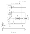
- FIG. 1 is a diagram for explaining a method and apparatus for adjusting the optical axis of a laser beam according to a first embodiment of the present invention.
- FIG. 2 is a block diagram showing a laser processing apparatus according to the first embodiment of the present invention.
- FIG. 3 is a block diagram showing an example of an illumination optical system.
- FIG. 4 is a diagram for explaining conditions for determining whether or not to perform an operation for correcting the optical axis of a laser beam.
- FIG. 5 is a diagram for explaining the correction direction of the optical axis of the laser beam.
- FIG. 6 is a diagram showing the results of optical axis adjustment.
- FIG. 7 is a graph showing the results of optical axis adjustment in the rolling direction.
- FIG. 1 is a diagram for explaining a method and apparatus for adjusting the optical axis of a laser beam according to a first embodiment of the present invention.
- FIG. 2 is a block diagram showing a laser processing apparatus according to the first embodiment of the present invention.
- FIG. 8 is a graph showing the influence on the beam profile at the processing point when the incident position on the optical element is shifted.
- FIG. 9 is a flowchart (Example 1) showing the optical axis correction method according to the first embodiment of the present invention.
- FIG. 10 is a flowchart (Example 2) showing the optical axis correction method according to the first embodiment of the present invention.
- FIG. 11 is a flowchart showing an optical axis adjustment method according to the second embodiment.
- FIG. 12 is a flowchart showing an optical axis adjustment method according to the second embodiment.
- FIG. 13 is a diagram showing the detection results of laser light before and after adjusting the position of the beam expander.
- FIG. 14 is a flowchart showing a first example of a method for determining the quality of a beam expander.
- FIG. 15 is a flowchart showing a second example of a method for determining the quality of a beam expander.
- FIG. 16 is a block diagram showing an example of an illumination optical system according to the fourth embodiment of the present invention.
- FIG. 17 is a diagram showing an example in which the position of the laser beam is detected at one detection point.
- FIG. 1 is a diagram for explaining a method and apparatus for adjusting the optical axis of a laser beam according to a first embodiment of the present invention.
- the system detects laser light (laser beam) output from a laser light source of a laser processing device at at least two detection points other than the processing point, and a unit for determining whether or not the position of the optical axis of the optical axis is normal.
- the position of the optical axis of the laser beam can be detected at two detection points OP1 and OP2 provided on the downstream side and upstream side of the optical element OE, respectively.
- the system according to the present embodiment includes an adjustment mechanism that adjusts the position or angle of the optical element holder that holds the optical element OE in accordance with the determination result regarding the position of the optical axis of the laser beam.
- Optical element holders that can be adjusted by such an adjustment mechanism can be provided at at least two locations on the optical path of the laser beam, for example.
- the optical axis of the laser beam can be limited to one by detecting the laser beam at two or more detection locations.
- the incident position and incident angle of the laser beam with respect to the optical element OE can be appropriately adjusted, and for example, the reflection angle of the mirror can be appropriately adjusted.
- the detection locations (OP1 and OP2) are two or more locations other than the processing point, but the present invention is not limited thereto.
- the two or more detection points (OP1 and OP2) may include a processing point that is a laser beam irradiation position on the workpiece.
- Laser processing equipment The method and apparatus for adjusting the optical axis of a laser beam according to this embodiment will be specifically described below.
- FIG. 2 is a block diagram showing a laser processing apparatus according to the first embodiment of the present invention.
- the laser processing device 10 includes a stage 12 that moves a workpiece W (for example, a semiconductor wafer), a laser irradiation device 20 that irradiates the workpiece W with laser light, and a laser processing device 10 that and a control section 50 that controls each section.
- a workpiece W for example, a semiconductor wafer
- a laser irradiation device 20 that irradiates the workpiece W with laser light
- a laser processing device 10 that and a control section 50 that controls each section.
- stage 12 is parallel to the XY directions and perpendicular to the Z direction.
- the stage 12 is configured to be movable in the XYZ ⁇ directions, and holds the workpiece W by suction.
- the workpiece W is placed on the stage 12 with a backgrind tape (hereinafter referred to as BG tape) having an adhesive material attached to the surface on which devices are formed, and the backside facing upward in the figure.
- BG tape backgrind tape
- the surface of the workpiece W on the condensing lens 24 side will be referred to as the laser beam irradiation surface.
- the laser beam irradiation surface may be the surface (back surface) of the workpiece W opposite to the surface on the condensing lens 24 side.
- the workpiece W may be placed on the stage 12 with a dicing sheet having an adhesive material attached to one surface thereof and integrated with the frame via the dicing sheet.
- the laser irradiation device 20 is disposed at a position facing the workpiece W, and emits a processing laser beam L1 for forming a laser processing area on the workpiece W (for example, inside the workpiece W).
- the workpiece W is irradiated.
- the control unit 50 includes a CPU (Central Processing Unit), memory, storage device, input/output circuit unit, etc., and performs operations of each part of the laser processing apparatus 10 and storage of data necessary for processing.
- CPU Central Processing Unit
- memory volatile and non-volatile memory
- storage device non-volatile memory
- input/output circuit unit etc.
- the laser processing apparatus 10 also includes a wafer transport means, an operation panel, a monitor, an indicator light, etc. (not shown).
- the operation panel is equipped with switches and a display device for operating the operations of each part of the laser processing device 10.
- the television monitor displays a wafer image captured by a CCD (Charge Coupled Device) camera (not shown), program contents, various messages, and the like.
- the indicator light indicates the operating status of the laser processing device 10, such as during processing, completion of processing, or emergency stop.
- the laser irradiation device 20 includes a laser light source 21, an illumination optical system 22, a dichroic mirror 23, a condenser lens 24, an actuator 25, and an AF device 30.
- the laser light source 21 emits processing laser light (hereinafter also referred to as laser light) L1 for forming a laser processing region inside the workpiece W.
- laser light processing laser light
- the laser light source 21 emits a laser beam with a pulse width of 1 ⁇ s or less and a peak power density of 1 ⁇ 10 8 (W/cm 2 ) or more at the focal point.
- an illumination optical system 22, a dichroic mirror 23, and a condenser lens 24 are arranged in order from the laser light source 21 side.
- the dichroic mirror 23 transmits the processing laser beam L1 and reflects the AF laser beam L2 emitted from the AF device 30.
- the second optical path of the AF laser beam L2 is bent by the dichroic mirror 23 so as to partially share the optical path with the first optical path of the processing laser beam L1, and the condenser lens 24 is disposed on the shared optical path. Ru.
- the processing laser beam L1 emitted from the laser light source 21 passes through the illumination optical system 22 and the dichroic mirror 23, and then is condensed onto the workpiece W by the condenser lens 24.
- the Z-direction position (wafer thickness direction position) of the condensing point of the processing laser beam L1 is adjusted by slightly moving the condensing lens 24 in the Z-direction using the actuator 25.
- the AF device 30 receives the reflected light of the AF laser beam L2 irradiated onto the workpiece W, thereby obtaining information regarding the distance between the condenser lens 24 and the laser beam irradiation surface of the workpiece W (distance information). is output to the control section 50.
- the drive of the actuator 25 is controlled by the control unit 50 so that the distance between the condenser lens 24 and the laser beam irradiated surface of the workpiece W is maintained in a predetermined relationship (the distance is constant).
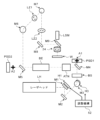
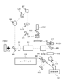
- FIG. 3 is a block diagram showing an example of an illumination optical system.
- FIG. 3 shows the optical path of the laser beam L1 from the laser head LH of the laser light source 21 to the workpiece W. Note that in FIG. 3, the dichroic mirror 23 is omitted.
- the laser head LH includes a condensing lens that condenses the laser beam L1 output from the laser oscillator of the laser light source 21, and outputs the condensed laser beam L1 to the workpiece W.
- the laser beam L1 is sequentially reflected by the mirrors M1 to M3 and the half mirror M4, and is emitted toward the attenuator ATN.
- the beam shutter BS controls emission of the laser beam L1 to the downstream side (mirror M4 side) according to the control of the control unit 50.
- the mirrors M1 and M3 (an example of a pair of movable mirrors) are held by holders H1 and H3, respectively, and the holders H1 and H3 are attached to, for example, gimbal-type mounts.
- Mirrors M1 and M3 are provided with adjustment mechanisms 52 (for example, , actuator, etc.).
- the beam diameter is expanded by the beam expander BE, and the beam is shaped into collimated light (parallel light).
- the laser beam L1 is directed to the workpiece W by the condenser lens 24 through optical elements such as the half mirror M5 and the mirror M6, the relay lens LZ1, the mirror M7, the relay lens LZ2, the mirror M8, and the half mirror M9. The light is focused.
- Position Sensitive Detectors PSD1 and PSD2 are placed on the downstream side of half mirrors M4 and M5 (an example of a pair of half mirrors (fixed mirrors)
- PSD1 and PSD2 are placed on the downstream side of half mirrors M4 and M5 (an example of a pair of half mirrors (fixed mirrors)
- PSD1 and PSD2 are placed on the downstream side of half mirrors M4 and M5 (an example of a pair of half mirrors (fixed mirrors)
- the position detection sensors PSD1 and PSD2 include, for example, a photodiode, and are sensors that detect the incident position of the laser beam L1 using the surface resistance of the photodiode. Position detection sensors PSD1 and PSD2 detect the incident positions of laser beams L1 that have passed through half mirrors M4 and M5, respectively. In the example shown in FIG. 3, the incident position of the laser beam L1 at each location is indicated by symbols A1 and A2.
- the optical axis adjustment device for laser light includes position detection sensors PSD1 and PSD2, and an adjustment mechanism 52 for mirrors M1 and M3.
- position detection sensors PSD1 and PSD2 for example, it is also possible to use a sensor that detects the incident position of the laser beam L1 using an image sensor.
- a laser scanning microscope detects the irradiation position of the laser beam L1 on the laser beam irradiation surface of the workpiece W.
- the laser microscope LSM is capable of monitoring the state of laser processing by constantly detecting the irradiation position of the laser beam L1 during laser processing, for example, via the half mirror M9.
- the number and arrangement of the position detection sensors PSD1 and PSD2 are not limited to those shown in FIG. 3.
- the number and arrangement of steering mirrors are not limited to those shown in FIG. 3, and mirrors other than mirrors M1 and M3 may be used as steering mirrors.
- the optical axis is adjusted by adjusting at least two mirrors M1 and M3, but the position and angle of optical elements other than the mirrors (for example, lenses, prisms, etc.)
- the optical axis may be adjusted by adjusting at least one of them.
- two position detection sensors PSD1 and PSD2 are used to detect the irradiation positions A1 and A2 of the laser beam L1, and depending on whether the irradiation positions A1 and A2 deviate from the allowable range, the mirrors M1 and M3 are The optical axis is corrected by driving the holders H1 and H3, which hold the holders H1 and H3, respectively.
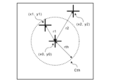
- FIG. 4 is a diagram for explaining the conditions for determining whether or not to perform an operation for correcting the optical axis of the laser beam
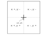
- FIG. 5 is a diagram for explaining the direction in which the optical axis of the laser beam is corrected. .
- the position detection sensors PSD1 and PSD2 are used to detect the irradiation position of the laser beam L1 at the time when the adjustment of the laser beam of the laser irradiation device 20 is completed, and the detected irradiation position of the laser beam L1 is set to the reference position. (standard value). Furthermore, a threshold value for determining optical axis deviation is set. In the example shown in FIG. 4, the reference value is (x0, y0) and the threshold value is rth.
- the irradiation position of the laser beam L1 is detected using the position detection sensors PSD1 and PSD2. Then, when the difference r between the irradiation position (current value) of the laser beam L1 and the reference value exceeds the threshold value rth, the steering mirrors M1 and M3 are driven to adjust the optical axis of the laser beam L1.
- the difference r between the current value of the laser beam L1 and the reference value is expressed by Equation 1 below.
- a circle Cth with a radius rth centered on the reference value (x0, y0) is shown. If the current values of the laser beam L1 detected using the position detection sensors PSD1 and PSD2 are both within the circle Cth (current value 1 (x1, y1), r1 ⁇ rth), optical axis adjustment is not performed. .
- optical axis adjustment is performed.
- the adjustment direction (movement direction) of the optical axis is as follows (see FIG. 5). ⁇ If xoff ⁇ 0, the direction of movement of the optical axis is the positive (+) direction of x. ⁇ If xoff>0, the direction of movement of the optical axis is the negative ( ⁇ ) direction of x. ⁇ If yoff ⁇ 0, the direction of movement of the optical axis is the positive (+) direction of x. The direction of movement is the positive (+) direction of y. If yoff>0, the direction of movement of the optical axis is the negative (-) direction of y.
- the irradiation position of the laser beam L1 may be re-detected using the position detection sensors PSD1 and PSD2, and the result of the optical axis adjustment may be confirmed. Also, use a power meter (not shown) to check the laser output (for example, attenuation amount) on the upstream side of the condenser lens 24 or at the processing point of the workpiece W, and check the result of optical axis adjustment based on the result. You may also do so.
- the laser output for example, attenuation amount
- FIG. 6 is a diagram showing the results of optical axis adjustment.
- the detection results of the laser beam L1 by the sensor PSD1 are shown arranged in a cross shape.
- the rolling direction is a direction around the axis of the traveling direction (optical axis direction) of the laser beam L1
- the pitching direction is a direction around the axis perpendicular to the traveling direction.
- the unit of the amount of movement of mirrors M1 and M3 (steering mirrors) is expressed in pulses. Note that the amount of movement of one pulse is approximately 1 ⁇ m.
- the beams of light extending in a cross shape from the laser beam L1 are approximately equal in the vertical and horizontal directions. Note that the shape and number of beams extending from the laser beam L1 may vary depending on the configuration of the optical elements included in the illumination optical system 22.
- control unit 50 when the control unit 50 detects a deviation from the reference position, it first drives the mirror M1 so that the detection result of the laser beam L1 by the position detection sensor PSD1 becomes the reference position. Next, the mirror M3 is driven so that the detection result of the laser beam L1 by the position detection sensor PSD2 becomes the reference position. Thereafter, by sequentially repeating the driving of the mirrors M1 and M3, the position of the laser beam L1 is converged to the reference position.
- FIG. 7 is a graph showing the results of optical axis adjustment in the rolling direction.
- FIG. 7(a) shows the optical axis adjustment result when the mirror M1 is moved by +500 pulses in the rolling direction
- FIG. 7(b) shows the optical axis adjustment result when the mirror M1 is moved by +300 pulses in the rolling direction.
- the results of optical axis adjustment are shown.
- Each graph shows a change over time in the amount of deviation ( ⁇ m) of the mirrors M1 and M3 from the reference position when the mirrors M1 and M3 are repeatedly driven.
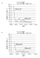
- FIG. 8 is a graph showing the influence on the beam profile at the processing point when the incident position on the optical element is shifted.
- FIG. 8 shows beam profiles at processing points when the amount of deviation from the reference position is 0 to 500 ⁇ m.
- the horizontal axis in FIG. 8 indicates pixels of the image sensor of the laser microscope LSM, and the vertical axis indicates the intensity of the laser beam L1.
- the position of the laser beam L1 is detected at at least two locations on the optical path of the laser beam L1, and the amount of deviation from the reference position is reduced (eliminated) by driving the mirrors M1 and M3. , variations in the beam profile as shown in FIG. 8 can be suppressed.
- FIG. 9 is a flowchart (Example 1) showing the optical axis correction method according to the first embodiment of the present invention.
- FIG. 9 shows an example in which the optical axis adjustment is performed, for example, when starting up the system of the laser processing apparatus 10 or manually.
- the laser processing apparatus 10 is started (step S10) and initialized (step S12), and then enters a laser idling state (step S14).
- the laser idling state is a state in which the laser beam L1 is output toward the processing point of the workpiece W.
- the irradiation position of the laser beam L1 is detected using the position detection sensors PSD1 and PSD2 (step S16), and the orientations of the mirrors M1 and M3 (steering mirror) are corrected (step S18). Then, as shown in FIG. 4, the orientations of the mirrors M1 and M3 are corrected until the irradiation position (current value) of the laser beam L1 matches the reference value or the difference r from the reference value becomes equal to or less than the threshold value rth. repeat.
- the threshold value at the time of optical axis adjustment at the time of starting up the system may be a smaller value than the threshold value rth at the time of determining the necessity of optical axis adjustment in FIG. 4.
- step S20 After the position of the irradiation position (processing point) of the laser beam L1 is confirmed by the laser microscope LSM (step S22), laser processing is performed (step S24).
- FIG. 10 is a flowchart (Example 2) showing the optical axis correction method according to the first embodiment of the present invention.
- FIG. 10 shows an example in which the laser processing apparatus 10 performs optical axis adjustment during execution of laser processing.
- a processing position confirmation operation is performed prior to the processing operation.
- it is OK if the difference r between the irradiation position (current value) of the laser beam L1 and the reference value is less than or equal to the threshold rth, and if it exceeds the threshold rth. It becomes NG. If it is OK in step S30, the process moves to the machining operation without executing the optical axis adjustment. On the other hand, in the case of NG in step S30, optical axis adjustment is executed (steps S52 to S56).
- the laser is in the idling state (step S52), the irradiation position of the laser beam L1 is detected using the position detection sensors PSD1 and PSD2 (step S54), and the directions of the mirrors M1 and M3 (steering mirror) are adjusted. Correct it (step S56). Then, the correction of the orientations of the mirrors M1 and M3 is repeated until the irradiation position (current value) of the laser beam L1 reaches the reference value or the difference r from the reference value becomes equal to or less than the threshold value rth.
- the threshold value when adjusting the optical axis in step S54 may be a smaller value than the threshold value rth when determining whether or not optical axis adjustment is necessary in step S30 and step S50, which will be described later.
- step S52 to S56 when the correction of the orientations of the mirrors M1 and M3 is completed (steps S52 to S56), the processing operation begins. Note that before the processing operation, a power check and a check of the position of the irradiation position (processing point) of the laser beam L1 may be performed.
- step S50 the irradiation position of the laser beam L1 by the position detection sensors PSD1 and PSD2 during execution of the immediately preceding machining operation is acquired (step S50), and it is determined whether or not optical axis adjustment is necessary, as in step S30. Then, in the case of OK in step S50, the process moves to the machining operation without executing the optical axis adjustment. On the other hand, in the case of NG in step S50, optical axis adjustment is executed (steps S52 to S56).
- step S70 the kerf formed by laser machining is checked (step S70), and the irradiation position of the laser beam L1 by the laser microscope LSM is checked (step S72).
- step S70 and step S72 are OK, the process moves to the next machining operation, and if both are NG, the position detection sensors PSD1 and PSD2 irradiate the laser beam L1 during the execution of the immediately previous machining operation.
- the position is acquired (step S74), and similarly to step S50, it is determined whether or not optical axis adjustment is necessary. Note that only one of Step S70 and Step S72 may be performed.
- step S74 optical axis adjustment is executed (steps S52 to S56).
- step S74 the kerf check error and the error in the detection position of the laser microscope LSM require a response other than optical axis adjustment, so an error message is output without performing optical axis adjustment.
- the machining operation is stopped (step S76).
- the optical axis of the laser beam L1 can be limited to one.
- the laser beam L1 can be made to enter the optical element perpendicularly, or the reflection angle on the mirror can be limited to 45 degrees.
- fluctuations in the positional relationship between the optical element and the laser beam can be suppressed to 50 ⁇ m or less, and the quality of laser processing can be maintained automatically without the intervention of an engineer. becomes.
- the pointing stability of the laser head LH deteriorates due to changes in the temperature of the external environment, and the irradiation position of the laser beam L1 shifts. Even if the irradiation position of the laser beam L1 incident on the beam expander BE changes, by performing the optical axis adjustment according to this embodiment, it is possible to eliminate the deviation of the irradiation position of the laser beam L1.
- the optical axis was adjusted according to the position of the laser beam L1 detected using the position detection sensors PSD1 and PSD2, but the deviation of the beam expander BE also affects the beam profile at the processing point. It can affect the quality of laser processing. Therefore, in addition to or in place of the above embodiments, it is also conceivable to adjust the optical axis of the beam expander BE.
- the beam expander BE can appear and disappear on the optical path of the laser beam L1.
- the movement of the beam expander BE to move in and out may be performed manually or automatically by an actuator that can be controlled by the control unit 50.
- 11 and 12 are flowcharts showing the optical axis adjustment method according to the second embodiment.
- symbol is attached
- optical axis adjustment (pre-adjustment) before the start of laser processing will be described with reference to FIG. 11.
- the position of the laser beam L1 is detected using the position detection sensors PSD1 and PSD2 (step S100).
- the beam expander BE is moved onto the optical path of the laser beam L1, and the magnification of the beam expander BE is set to 1x. Then, the position of the laser beam L1 when the beam expander BE is moved onto the optical path of the laser beam L1 is made to match the position of the laser beam L1 when the beam expander BE is retreated from the optical path of the laser beam L1. By doing so, the optical axis is adjusted (step S102).
- step S102 the position of the laser beam L1 when the beam expander BE is moved onto the optical path of the laser beam L1 is changed from the position of the laser beam L1 when the beam expander BE is moved from the optical path of the laser beam L1. It does not have to match the position exactly.
- the difference between the position of the laser beam L1 when the beam expander BE is moved onto the optical path of the laser beam L1 and the position of the laser beam L1 when the beam expander BE is moved from the optical path of the laser beam L1. may be less than or equal to a predetermined threshold.
- the magnification of the beam expander BE is set to a magnification necessary for laser processing (step S110), and the position of the laser beam L1 is detected and recorded using the position detection sensors PSD1 and PSD2 (step S112).
- step S114 the position of the laser beam L1 is detected using the position detection sensors PSD1 and PSD2 (step S114).
- step S114 as in FIG. 4, it is determined as OK if the difference r between the irradiation position (current value) of the laser beam L1 and the reference value is less than or equal to the threshold rth, and determined as NG if it exceeds the threshold rth. If it is OK in step S114, the processing operation is continued without executing the optical axis adjustment. On the other hand, if the result in step S114 is NG, optical axis adjustment is performed (step S116).
- step S116 similarly to step S102, the magnification of the beam expander BE is set to 1, and the position of the laser beam L1 with the beam expander BE moved onto the optical path of the laser beam L1 is Optical axis adjustment is performed by matching the position of the laser beam L1 with the panda BE retreated from the optical path of the laser beam L1.
- step S116 when the optical axis adjustment (step S116) is completed, the magnification of the beam expander BE is set to the magnification necessary for laser processing (step S110), and the position of the laser beam L1 is determined using the position detection sensors PSD1 and PSD2. After detection and recording, laser processing continues. Then, when the laser processing is completed (step S118), the apparatus is stopped.
- the kerf check error and the detection position of the laser microscope LSM may be checked after step S118.
- FIG. 13 is a diagram showing the detection results of the laser beam L1 before and after adjusting the position of the beam expander. In FIG. 13, it is assumed that the lighter the color, the higher the intensity of the laser beam L1.
- the beam profile of the laser beam L1 is biased, as shown in FIG. 13(b).
- the beam profile becomes uniform in the rolling direction and the pitching direction, as shown in FIG. 13(a). It has a roughly circular shape with a distribution of .
- the magnification of the beam expander BE is set to 1x during optical axis adjustment (steps S102 and S116), but the present invention is not limited to this.
- the magnification of the beam expander BE may be set to a magnification other than 1. Further, both the optical axis adjustment performed by setting the magnification of the beam expander BE to 1x and the optical axis adjustment performed by setting the magnification of the beam expander BE to a magnification other than 1x may be performed.
- the beam expander BE When the magnification of the beam expander BE is set to 1, the beam expander BE can be considered to be optically equivalent to a transparent flat plate. In this case, the position of the laser beam L1 when the beam expander BE is moved onto the optical path of the laser beam L1 is different from the position of the laser beam L1 when the beam expander BE is moved from the optical path of the laser beam L1.
- the difference (shift amount) can be evaluated as being caused by the inclination (tilt) of the beam expander BE with respect to the optical axis of the laser beam L1.
- the position of the laser beam L1 when the beam expander BE is moved onto the optical path of the laser beam L1 is the same as the position of the laser beam L1 when the beam expander BE is moved from the optical path of the laser beam L1. , and the amount of deviation is made approximately zero (see steps S102 and S116).
- the tilt of the beam expander BE with respect to the optical axis of the laser beam L1 can be adjusted, and the optical axis of the beam expander BE can be made parallel to the optical axis of the laser beam L1.
- the beam diameter of the laser beam L1 is expanded according to the set magnification.
- the position of the laser beam L1 when the beam expander BE is moved onto the optical path of the laser beam L1 is different from the position of the laser beam L1 when the beam expander BE is moved from the optical path of the laser beam L1.
- the difference (shift amount) can be evaluated as being caused by parallel shift.
- the parallel deviation is a deviation of the optical axis of the beam expander BE with respect to the optical axis of the laser beam L1, and appears as a deviation of the incident position on a plane perpendicular to the optical axis of the laser beam L1.
- the position of the laser beam L1 when the beam expander BE is moved onto the optical path of the laser beam L1 is the same as the position of the laser beam L1 when the beam expander BE is retracted from the optical path of the laser beam L1.
- the amount of deviation is made approximately zero (see steps S102 and S116).
- the tilt and parallel deviation of the beam expander BE can be adjusted.
- the optical axis can be adjusted by rotating the beam expander BE with respect to the optical axis of the laser beam L1.
- the adjustment axis of the beam expander BE is limited to the parallel direction. That is, the optical axis can be adjusted by moving the beam expander BE while maintaining its inclination with respect to the optical axis of the laser beam L1. That is, the adjustment axis for optical axis adjustment can be limited depending on whether the magnification of the beam expander BE is 1x or other than 1x.
- the abnormality of the beam expander BE includes, for example, a case where the lenses included in the beam expander BE are not coaxial with each other, a case where the inclinations of the lenses are different, and the like.
- the coordinates of the irradiation position of the laser beam L1 move differently (for example, nonlinearly) than when the beam expander BE is normal. .
- the quality of the beam expander BE is determined using the above properties. Note that the quality of the beam expander BE can be determined regardless of whether or not the optical axis adjustment described above is performed.
- FIG. 14 is a flowchart showing a first example of a method for determining the quality of a beam expander.
- FIG. 14 shows the quality determination method when the optical axis adjustment of the beam expander BE has already been performed.
- the laser processing apparatus 10 when the laser processing apparatus 10 is started and initialized, it enters a laser idling state (step S200). Then, the magnification of the beam expander BE is changed, and the irradiation position of the laser beam L1 at each magnification is detected and recorded (step S202).
- step S204 it is determined whether the amount of movement of the irradiation position of the laser beam L1 due to the change in the magnification of the beam expander BE is less than or equal to a reference value (step S204).
- the reference value in step S204 is, for example, a positive value close to zero.
- step S206 If the amount of movement of the irradiation position of the laser beam L1 due to the change in the magnification of the beam expander BE is less than or equal to the reference value (Yes in step S204), it is determined that the quality of the beam expander BE is good (step S206).
- step S208 If the amount of movement of the irradiation position of the laser beam L1 due to the change in the magnification of the beam expander BE exceeds the reference value (No in step S204), it is determined that the quality of the beam expander BE is poor (step S208).
- FIG. 15 is a flowchart showing a second example of a method for determining the quality of a beam expander.
- FIG. 15 shows the quality determination method when the optical axis adjustment of the beam expander BE has not been performed.
- the laser processing apparatus 10 when the laser processing apparatus 10 is started and initialized, it enters a laser idling state (step S220). Then, the magnification of the beam expander BE is changed, and the irradiation position of the laser beam L1 at each magnification is detected and recorded (step S222).
- step S224 it is determined whether the irradiation position of the laser beam L1 moves linearly as the magnification of the beam expander BE changes.
- step S224 it is evaluated whether the irradiation position of the laser beam L1 moves linearly, for example, depending on whether the correlation coefficient when the irradiation position of the laser beam L1 is plotted for each magnification is close to 1 or not. can do.
- step S224 If it is determined that the irradiation position of the laser beam L1 moves linearly with the change in the magnification of the beam expander BE (Yes in step S224), it is determined that the quality of the beam expander BE is good (step S226).
- step S224 If it is determined that the irradiation position of the laser beam L1 is not linearly moved due to the change in the magnification of the beam expander BE (No in step S224), it is determined that the quality of the beam expander BE is poor (step S226).
- the quality of the beam expander BE can be determined, for example, before and after the optical axis adjustment.
- the quality of the beam expander BE can be determined before the optical axis adjustment, and the beam expander BE can be adjusted or replaced. This makes it possible to improve the accuracy of optical axis adjustment using the beam expander BE.
- timing of performing the quality determination of the beam expander BE is not particularly limited.
- the quality determination of the beam expander BE can also be performed, for example, when starting up the system or while performing laser processing.
- FIG. 16 is a block diagram showing an example of an illumination optical system according to the fourth embodiment of the present invention.
- FIG. 16 shows an example in which a laser beam shaping optical element SE is arranged between a beam expander BE and a half mirror M5.
- the laser beam shaping optical element SE is an optical element for adjusting the state of the laser beam L1 from the beam expander BE. Specifically, the laser beam shaping optical element SE shapes the laser beam L1 from the beam expander BE in accordance with the content of laser processing in the laser processing apparatus 10.
- the content of the laser processing includes, for example, grooving, scribing, cutting, or drilling by laser ablation, or the formation of a laser processing area that becomes a starting point for cutting (crack) of the workpiece W.
- the laser beam shaping optical element SE includes, for example, a refractive optical element (ROE), a cylindrical lens, or a mask.
- the ROE is a refractive optical element for shaping the beam shape of the laser beam L1 into a desired shape (for example, a circle, a ring shape, a line shape, a rectangle, a polygon, etc.).
- the cylindrical lens is a lens that includes a cylindrical portion, and can shape the laser beam L1 into a linear beam shape, or expand or contract the laser beam L1 in only one direction on a plane perpendicular to its optical axis.
- the mask is an optical element for shaping the beam shape of the laser light L1 by blocking a portion of the laser light L1.
- the accuracy of the irradiation position when the laser beam L1 from the beam expander BE is irradiated onto the laser beam shaping optical element SE is improved. can be increased. Thereby, the shaping result of the laser beam L1 irradiated to the laser beam shaping optical element SE can be stabilized.
- the laser beam shaping optical element SE is arranged between the beam expander BE and the half mirror M5, but the present invention is not limited thereto.
- the laser beam shaping optical element SE may be placed between the half mirror M5 and the mirror M6, or may be placed at another location (downstream of the beam expander BE).
- SYMBOLS 10 Laser processing device, 12... Stage, 20... Laser irradiation device, 21... Laser light source, 22... Illumination optical system, 23... Dichroic mirror, 24... Condenser lens, 25... Actuator, 30... AF device, 50... Control Section, 52...Adjustment mechanism, H1, H3...Holder, M1-M3, M6-M8...Mirror, M4-M5, M9...Half mirror, PSD1-PSD2...Position detection sensor, LH...Laser head, ATN...Attenuator, BE ...Beam expander, LZ1, LZ2...Relay lens, LSM...Laser microscope, SE...Optical element for laser beam shaping
Landscapes
- Physics & Mathematics (AREA)
- Optics & Photonics (AREA)
- Engineering & Computer Science (AREA)
- Plasma & Fusion (AREA)
- Mechanical Engineering (AREA)
- General Physics & Mathematics (AREA)
- Laser Beam Processing (AREA)
- Mounting And Adjusting Of Optical Elements (AREA)
- Lasers (AREA)
Abstract
Description
(レーザ光の光軸調整方法及び装置の概要)
図1は、本発明の第1の実施形態に係るレーザ光の光軸調整方法及び装置を説明するための図である。
以下、本実施形態に係るレーザ光の光軸調整方法及び装置について具体的に説明する。
次に、照明光学系22の例について図3を参照して説明する。図3は、照明光学系の例を示すブロック図である。
以下、2個の位置検出センサPSD1及びPSD2を用いてレーザ光L1の光軸補正を行う手順について説明する。

・xoff<0の場合、光軸の移動方向はxの正(+)方向
・xoff>0の場合、光軸の移動方向はxの負(-)方向
・yoff<0の場合、光軸の移動方向はyの正(+)方向
・yoff>0の場合、光軸の移動方向はyの負(-)方向
次に、本実施形態に係る光軸補正方法について説明する。
図10は、本発明の第1の実施形態に係る光軸補正方法を示すフローチャート(例2)である。図10は、レーザ加工装置10によりレーザ加工の実行中に光軸調整を行う例を示している。
上記の実施形態では、位置検出センサPSD1及びPSD2を用いて検出したレーザ光L1の位置に応じて光軸調整を行ったが、ビームエキスパンダBEのずれも加工点におけるビームプロファイルに影響を与え、レーザ加工の品質に影響を与え得る。このため、上記の実施形態に加えて又は上記の実施形態に代えて、ビームエキスパンダBEについても光軸調整を行うことも考えられる。
本実施形態では、光軸調整の際にビームエキスパンダBEの倍率を1倍に設定したが(ステップS102及びS116)、本発明はこれに限定されない。光軸調整の際にビームエキスパンダBEの倍率を1倍以外の倍率に設定してもよい。また、ビームエキスパンダBEの倍率を1倍に設定して行う光軸調整と、ビームエキスパンダBEの倍率を1倍以外の倍率に設定して行う光軸調整とを両方行ってもよい。
上記の各実施形態では、ビームエキスパンダBEが正常である場合について説明したが、ビームエキスパンダBEに異常がある場合も考えられる。ここで、ビームエキスパンダBEの異常は、例えば、ビームエキスパンダBEに含まれるレンズが互いに同軸になっていない場合、各レンズの傾きが異なっている場合等を含む。
図16は、本発明の第4の実施形態に係る照明光学系の例を示すブロック図である。図16は、ビームエキスパンダBEとハーフミラーM5との間にレーザ光整形用光学素子SEを配置した例を示している。
Claims (11)
- ビームエキスパンダの上流側と下流側にそれぞれ固定された一対のハーフミラーを透過した位置にそれぞれ配置された一対の位置検出センサにより、レーザ光源から被加工物に向けて出力されたレーザ光の位置を検出するステップと、
前記レーザ光の位置に基づいて、前記レーザ光の光路上の前記ハーフミラーよりもレーザ光源側に配置された一対の可動ミラーの位置及び角度のうちの少なくとも一方を調整して前記レーザ光の光軸調整を行うステップと、
を含むレーザ光の光軸調整方法。 - 前記一対の位置検出センサは、前記被加工物において前記レーザ光が照射される加工点以外に設けられる、請求項1に記載のレーザ光の光軸調整方法。
- 前記一対の位置検出センサにより検出された前記レーザ光の位置と予め設定された基準値との差が閾値以上の場合に、前記レーザ光の光軸調整を行う、請求項1又は2に記載のレーザ光の光軸調整方法。
- 前記一対の可動ミラーのうちの1枚の可動ミラーの位置及び角度のうちの少なくとも一方を調整して、前記一対の位置検出センサのうちの1つの位置検出センサにより検出した前記レーザ光の位置を基準値とすることを前記可動ミラーごとに繰り返して、各位置検出センサにより検出した前記レーザ光の位置をそれぞれ基準位置に収束させる、請求項3に記載のレーザ光の光軸調整方法。
- ビームエキスパンダの上流側と下流側にそれぞれ固定された一対のハーフミラーを透過した位置にそれぞれ配置された一対の位置検出センサと、
前記位置検出センサにより検出したレーザ光の位置に基づいて、前記レーザ光の光路上の前記ハーフミラーよりもレーザ光源側に配置された一対の可動ミラーの位置及び角度のうちの少なくとも一方を調整して前記レーザ光の光軸調整を行う調整機構と、
を備えるレーザ光の光軸調整装置。 - ビームエキスパンダの上流側と下流側にそれぞれ配置された位置検出センサにより、レーザ光源から被加工物に向けて出力されたレーザ光の位置を検出するステップと、
前記レーザ光の光路上に前記ビームエキスパンダを配置した状態において前記位置検出センサにより検出した前記レーザ光の位置と、前記レーザ光の光路から前記ビームエキスパンダを退避させた状態において前記位置検出センサにより検出した前記レーザ光の位置に基づいて、前記ビームエキスパンダを移動させて前記レーザ光の光軸調整を行うステップと、
を含むレーザ光の光軸調整方法。 - 前記光軸調整を行うステップでは、前記ビームエキスパンダの倍率を1倍に設定した状態における前記レーザ光の位置を、前記ビームエキスパンダを前記レーザ光の光路上から退避させた状態における前記レーザ光の位置に合わせて調整する、請求項6に記載のレーザ光の光軸調整方法。
- 前記光軸調整を行うステップでは、前記ビームエキスパンダの倍率を1倍以外に設定した状態における前記レーザ光の位置を、前記ビームエキスパンダを前記レーザ光の光路上から退避させた状態における前記レーザ光の位置に合わせて調整する、請求項6又は7に記載のレーザ光の光軸調整方法。
- 前記ビームエキスパンダの倍率を変化させた場合に、前記位置検出センサにより検出した前記レーザ光の位置の変化に基づいて、前記ビームエキスパンダの良否判定を行うステップを備える、請求項6から8のいずれか1項に記載のレーザ光の光軸調整方法。
- 前記良否判定を行うステップでは、前記ビームエキスパンダの倍率の変化に応じて、前記位置検出センサにより検出した前記レーザ光の位置の移動量が基準値以下か、又は前記レーザ光の位置が線形に変化した場合に、前記ビームエキスパンダの品質が良であると判定する、請求項9に記載のレーザ光の光軸調整方法。
- レーザ光源から被加工物に向けて出力されたレーザ光の光路上に出没可能に配置されたビームエキスパンダと、
前記ビームエキスパンダの上流側と下流側にそれぞれ配置された位置検出センサと、
前記レーザ光の光路上に前記ビームエキスパンダを配置した状態において前記位置検出センサにより検出した前記レーザ光の位置と、前記レーザ光の光路から前記ビームエキスパンダを退避させた状態において前記位置検出センサにより検出した前記レーザ光の位置に基づいて、前記ビームエキスパンダを移動させて前記レーザ光の光軸調整を行う調整機構と、
を備えるレーザ光の光軸調整装置。
Priority Applications (4)
| Application Number | Priority Date | Filing Date | Title |
|---|---|---|---|
| KR1020247032052A KR20240150602A (ko) | 2022-03-28 | 2023-03-15 | 레이저 광의 광축 조정 방법 및 장치 |
| DE112023001601.1T DE112023001601T5 (de) | 2022-03-28 | 2023-03-15 | Verfahren und Vorrichtung zur Justierung einer optischen Achse von Laserlicht |
| CN202380030548.8A CN118946427A (zh) | 2022-03-28 | 2023-03-15 | 激光的光轴调整方法及装置 |
| US18/898,920 US20250018501A1 (en) | 2022-03-28 | 2024-09-27 | Method and device for adjusting optical axis of laser light |
Applications Claiming Priority (6)
| Application Number | Priority Date | Filing Date | Title |
|---|---|---|---|
| JP2022-052255 | 2022-03-28 | ||
| JP2022052255 | 2022-03-28 | ||
| JP2022191842A JP7212299B1 (ja) | 2022-03-28 | 2022-11-30 | レーザ光の光軸調整方法及び装置 |
| JP2022-191843 | 2022-11-30 | ||
| JP2022-191842 | 2022-11-30 | ||
| JP2022191843A JP7247453B1 (ja) | 2022-03-28 | 2022-11-30 | レーザ光の光軸調整方法及び装置 |
Related Child Applications (1)
| Application Number | Title | Priority Date | Filing Date |
|---|---|---|---|
| US18/898,920 Continuation US20250018501A1 (en) | 2022-03-28 | 2024-09-27 | Method and device for adjusting optical axis of laser light |
Publications (1)
| Publication Number | Publication Date |
|---|---|
| WO2023189591A1 true WO2023189591A1 (ja) | 2023-10-05 |
Family
ID=85014942
Family Applications (1)
| Application Number | Title | Priority Date | Filing Date |
|---|---|---|---|
| PCT/JP2023/010046 Ceased WO2023189591A1 (ja) | 2022-03-28 | 2023-03-15 | レーザ光の光軸調整方法及び装置 |
Country Status (7)
| Country | Link |
|---|---|
| US (1) | US20250018501A1 (ja) |
| JP (3) | JP7212299B1 (ja) |
| KR (1) | KR20240150602A (ja) |
| CN (1) | CN118946427A (ja) |
| DE (1) | DE112023001601T5 (ja) |
| TW (1) | TW202347906A (ja) |
| WO (1) | WO2023189591A1 (ja) |
Families Citing this family (1)
| Publication number | Priority date | Publication date | Assignee | Title |
|---|---|---|---|---|
| JP2024164609A (ja) * | 2023-05-15 | 2024-11-27 | 株式会社デンソー | レーザ加工装置の調整方法 |
Citations (7)
| Publication number | Priority date | Publication date | Assignee | Title |
|---|---|---|---|---|
| JP2005128162A (ja) * | 2003-10-22 | 2005-05-19 | Pentax Corp | 直描装置の光軸調整装置 |
| JP2011031284A (ja) * | 2009-08-03 | 2011-02-17 | Hamamatsu Photonics Kk | レーザ加工方法 |
| JP2011110560A (ja) * | 2009-11-24 | 2011-06-09 | Phoeton Corp | レーザー加工装置及びレーザー加工方法 |
| JP2012028569A (ja) * | 2010-07-23 | 2012-02-09 | Sumitomo Heavy Ind Ltd | 光軸調整方法及びレーザ加工装置 |
| JP2013202658A (ja) * | 2012-03-28 | 2013-10-07 | Toray Eng Co Ltd | レーザの光軸アライメント方法およびそれを用いたレーザ加工装置 |
| JP2014219199A (ja) * | 2013-04-12 | 2014-11-20 | 住友重機械工業株式会社 | レーザビーム観測装置 |
| JP2020003779A (ja) * | 2018-05-09 | 2020-01-09 | エヌピエス カンパニー リミテッド | レーザ装置 |
Family Cites Families (4)
| Publication number | Priority date | Publication date | Assignee | Title |
|---|---|---|---|---|
| CN201664817U (zh) | 2010-04-01 | 2010-12-08 | 东莞市开泰激光科技有限公司 | 激光切割机光路传输结构 |
| JP6385898B2 (ja) | 2015-07-15 | 2018-09-05 | 三菱重工業株式会社 | レーザ光の反射スポットの位置検出システム、レーザ光軸アライメントシステム及びレーザ光軸アライメント方法 |
| JP7285694B2 (ja) | 2019-05-23 | 2023-06-02 | 株式会社ディスコ | レーザー加工装置の光軸調整方法 |
| CN212286276U (zh) | 2020-05-28 | 2021-01-05 | 锡凡半导体无锡有限公司 | 扩束反射组件 |
-
2022
- 2022-11-30 JP JP2022191842A patent/JP7212299B1/ja active Active
- 2022-11-30 JP JP2022191843A patent/JP7247453B1/ja active Active
-
2023
- 2023-03-02 JP JP2023032097A patent/JP7398038B2/ja active Active
- 2023-03-15 CN CN202380030548.8A patent/CN118946427A/zh active Pending
- 2023-03-15 WO PCT/JP2023/010046 patent/WO2023189591A1/ja not_active Ceased
- 2023-03-15 DE DE112023001601.1T patent/DE112023001601T5/de active Pending
- 2023-03-15 KR KR1020247032052A patent/KR20240150602A/ko active Pending
- 2023-03-27 TW TW112111488A patent/TW202347906A/zh unknown
-
2024
- 2024-09-27 US US18/898,920 patent/US20250018501A1/en active Pending
Patent Citations (7)
| Publication number | Priority date | Publication date | Assignee | Title |
|---|---|---|---|---|
| JP2005128162A (ja) * | 2003-10-22 | 2005-05-19 | Pentax Corp | 直描装置の光軸調整装置 |
| JP2011031284A (ja) * | 2009-08-03 | 2011-02-17 | Hamamatsu Photonics Kk | レーザ加工方法 |
| JP2011110560A (ja) * | 2009-11-24 | 2011-06-09 | Phoeton Corp | レーザー加工装置及びレーザー加工方法 |
| JP2012028569A (ja) * | 2010-07-23 | 2012-02-09 | Sumitomo Heavy Ind Ltd | 光軸調整方法及びレーザ加工装置 |
| JP2013202658A (ja) * | 2012-03-28 | 2013-10-07 | Toray Eng Co Ltd | レーザの光軸アライメント方法およびそれを用いたレーザ加工装置 |
| JP2014219199A (ja) * | 2013-04-12 | 2014-11-20 | 住友重機械工業株式会社 | レーザビーム観測装置 |
| JP2020003779A (ja) * | 2018-05-09 | 2020-01-09 | エヌピエス カンパニー リミテッド | レーザ装置 |
Also Published As
| Publication number | Publication date |
|---|---|
| JP7212299B1 (ja) | 2023-01-25 |
| JP2023145329A (ja) | 2023-10-11 |
| US20250018501A1 (en) | 2025-01-16 |
| JP7398038B2 (ja) | 2023-12-14 |
| CN118946427A (zh) | 2024-11-12 |
| DE112023001601T5 (de) | 2025-01-23 |
| JP2023145328A (ja) | 2023-10-11 |
| TW202347906A (zh) | 2023-12-01 |
| JP2023145360A (ja) | 2023-10-11 |
| JP7247453B1 (ja) | 2023-03-29 |
| KR20240150602A (ko) | 2024-10-15 |
Similar Documents
| Publication | Publication Date | Title |
|---|---|---|
| EP2769800B1 (en) | Laser processing machine | |
| US9870961B2 (en) | Wafer processing method | |
| KR101161630B1 (ko) | 레이저 어닐링 방법 및 레이저 어닐링 장치 | |
| TW200300372A (en) | Laser machining apparatus | |
| JPWO2020090075A1 (ja) | 加工システム、及び、加工方法 | |
| JP4977411B2 (ja) | レーザー加工装置 | |
| KR20160127461A (ko) | 레이저 가공 장치 및 그 가공방법 | |
| JP5094337B2 (ja) | レーザ加工方法 | |
| JP2008215829A (ja) | 較正用治具、較正方法、及び該方法を用いたレーザ加工装置 | |
| US6515296B1 (en) | Pattern dimension measuring system and pattern dimension measuring method | |
| KR102483670B1 (ko) | 레이저 가공 시스템 및 레이저 가공 방법 | |
| JP7398038B2 (ja) | ビームエキスパンダの良否判定方法 | |
| KR20220146323A (ko) | 레이저 가공 장치의 조정 방법, 및 레이저 가공 장치 | |
| JP5420890B2 (ja) | チャックテーブルに保持された被加工物の高さ位置計測装置 | |
| TW201944157A (zh) | 雷射光線的焦點位置檢測方法 | |
| US12459055B2 (en) | Laser irradiation apparatus and laser irradiation method | |
| KR102052102B1 (ko) | 레이저 가공 장치 및 레이저 가공 장치의 캘리브레이션 방법 | |
| JP3218466B2 (ja) | 露光方法及び装置 | |
| EP3098910B1 (en) | Laser processing machine and focusing angle setting method of laser processing machine | |
| CN114101925B (zh) | 激光加工装置和聚光点位置的校正方法 | |
| KR20230078117A (ko) | 레이저 빔 중심 검출 장치 | |
| KR20150126810A (ko) | 자동 초점 조절 기능을 가진 레이저 마킹 장치 | |
| TWI900227B (zh) | 用於雷射加工的定位調整系統及其操作方法 | |
| KR20190109345A (ko) | 자동 초점 조절 기능을 가진 레이저 마킹 장치 | |
| TW201032936A (en) | System and method for laser processing |
Legal Events
| Date | Code | Title | Description |
|---|---|---|---|
| 121 | Ep: the epo has been informed by wipo that ep was designated in this application |
Ref document number: 23779609 Country of ref document: EP Kind code of ref document: A1 |
|
| ENP | Entry into the national phase |
Ref document number: 20247032052 Country of ref document: KR Kind code of ref document: A |
|
| WWE | Wipo information: entry into national phase |
Ref document number: 202380030548.8 Country of ref document: CN Ref document number: 1020247032052 Country of ref document: KR |
|
| WWE | Wipo information: entry into national phase |
Ref document number: 112023001601 Country of ref document: DE |
|
| 122 | Ep: pct application non-entry in european phase |
Ref document number: 23779609 Country of ref document: EP Kind code of ref document: A1 |