WO2023182318A1 - 接合構造および接合構造の構築方法 - Google Patents
接合構造および接合構造の構築方法 Download PDFInfo
- Publication number
- WO2023182318A1 WO2023182318A1 PCT/JP2023/011058 JP2023011058W WO2023182318A1 WO 2023182318 A1 WO2023182318 A1 WO 2023182318A1 JP 2023011058 W JP2023011058 W JP 2023011058W WO 2023182318 A1 WO2023182318 A1 WO 2023182318A1
- Authority
- WO
- WIPO (PCT)
- Prior art keywords
- beams
- girder
- floor slab
- small
- concrete floor
- Prior art date
- Legal status (The legal status is an assumption and is not a legal conclusion. Google has not performed a legal analysis and makes no representation as to the accuracy of the status listed.)
- Ceased
Links
Images





Classifications
-
- E—FIXED CONSTRUCTIONS
- E04—BUILDING
- E04B—GENERAL BUILDING CONSTRUCTIONS; WALLS, e.g. PARTITIONS; ROOFS; FLOORS; CEILINGS; INSULATION OR OTHER PROTECTION OF BUILDINGS
- E04B1/00—Constructions in general; Structures which are not restricted either to walls, e.g. partitions, or floors or ceilings or roofs
- E04B1/18—Structures comprising elongated load-supporting parts, e.g. columns, girders, skeletons
- E04B1/24—Structures comprising elongated load-supporting parts, e.g. columns, girders, skeletons the supporting parts consisting of metal
-
- E—FIXED CONSTRUCTIONS
- E04—BUILDING
- E04B—GENERAL BUILDING CONSTRUCTIONS; WALLS, e.g. PARTITIONS; ROOFS; FLOORS; CEILINGS; INSULATION OR OTHER PROTECTION OF BUILDINGS
- E04B1/00—Constructions in general; Structures which are not restricted either to walls, e.g. partitions, or floors or ceilings or roofs
- E04B1/38—Connections for building structures in general
- E04B1/58—Connections for building structures in general of bar-shaped building elements
-
- E—FIXED CONSTRUCTIONS
- E04—BUILDING
- E04B—GENERAL BUILDING CONSTRUCTIONS; WALLS, e.g. PARTITIONS; ROOFS; FLOORS; CEILINGS; INSULATION OR OTHER PROTECTION OF BUILDINGS
- E04B5/00—Floors; Floor construction with regard to insulation; Connections specially adapted therefor
- E04B5/16—Load-carrying floor structures wholly or partly cast or similarly formed in situ
- E04B5/32—Floor structures wholly cast in situ with or without form units or reinforcements
- E04B5/36—Floor structures wholly cast in situ with or without form units or reinforcements with form units as part of the floor
- E04B5/38—Floor structures wholly cast in situ with or without form units or reinforcements with form units as part of the floor with slab-shaped form units acting simultaneously as reinforcement; Form slabs with reinforcements extending laterally outside the element
- E04B5/40—Floor structures wholly cast in situ with or without form units or reinforcements with form units as part of the floor with slab-shaped form units acting simultaneously as reinforcement; Form slabs with reinforcements extending laterally outside the element with metal form-slabs
Definitions
- the present invention relates to a joining structure and a method of constructing a joining structure.
- Beam end connections such as between RC beams or walls and girders, or between girders and sub-beams, are generally designed as rigid or pin connections.
- the support member is a large beam
- the upper and lower flanges of the small beam are welded or bolted to the large beam, and the web of the small beam is bolted to the large beam.
- the web of the small beam is bolted to the fin plate (also called shear plate, gusset plate, etc.) attached to the main beam, and the upper and lower flanges of the small beam are not connected to the main beam.
- Non-Patent Document 1 there is a gravity frame that does not bear horizontal force, a moment frame that does not cause antisymmetrical bending when the horizontal force is small, and the beam and floor under load conditions where the moment at the joint does not reverse.
- a composite structure in which the slab is integrated with a shear connector is described.
- the rigidity of the joint can be easily increased.
- EUROPEAN COMMITTEE FOR STANDARDIZATION “Eurocode 4: Design of composite steel and concrete structures Part 1-1: General rules and rules for buildings”, April 2009
- reinforcing reinforcing bars that span the large beam are used to mutually transmit the tensile force acting on the upper flange sides of the small beams connected to both sides of the large beam.
- reinforcing bars could only be placed after other reinforcing bars had been placed in the sections on both sides of the girder, which caused problems in terms of workability.
- the vertical load supported by the floor slab creates a negative bending region in the floor slab around the joint between the large beam and the small beam, where tensile force acts on the slab.
- reinforcing steel bars in floor slabs resist tensile forces, but concrete has low resistance to tensile forces and is prone to cracking.
- reinforcing bars are placed along the axis of the beam, although the reinforcing bars contribute to reinforcing joints, their contribution to the direction of maximum deflection of the floor slab is limited. However, the effect was insufficient in terms of suppressing deflection and cracking of the floor slab.
- the present invention provides a joint structure in which a large beam and a small beam upper flange are joined via a concrete floor slab, and which can improve workability while ensuring the concrete cover thickness of the floor slab.
- the purpose of the present invention is to provide a method for constructing a joint structure that can prevent cracks in slabs.
- a girder having an H-shaped cross section, first and second small beams having an H-shaped cross section and extending in a direction intersecting the girder, the ends of which are opposite to each other with the girder in between, and first and second joining members that respectively join the webs of the first and second small beams to the main beam, wherein a concrete floor is provided above the main beam and the first and second small beams.
- a slab is constructed, wherein the upper flanges of the first and second crossbeams are respectively joined to the concrete floor slab and not directly joined to the girder and the first and second joint members; A joint structure in which reinforcing reinforcing bars embedded in concrete in a concrete floor slab are not placed above both the first and second beams.
- a slab is constructed, wherein the upper flanges of the first and second crossbeams are respectively joined to the concrete floor slab and not directly joined to the girder and the first and second joint members;
- the reinforcing reinforcing bars embedded in the concrete of the concrete floor slab have a joint structure in which at least a portion thereof extends in a direction obliquely intersecting the axis directions of the first and second beams.
- a concrete floor slab is constructed above the girder and the small beam, and the upper flange of the small beam is joined to the concrete floor slab and is not directly connected to the girder and the connecting member, but is connected to the small beam.
- the joint structure further comprises a tension member respectively locked to an upper flange or web of the beam and an upper flange or web of the girder.
- a girder having an H-shaped cross section, first and second small beams having an H-shaped cross section and extending in a direction intersecting the girder, the ends of which are opposite to each other across the girder, and and first and second joining members that respectively join the webs of the first and second small beams to the main beam, wherein a concrete floor is provided above the main beam and the first and second small beams.
- a slab is constructed, wherein the upper flanges of the first and second crossbeams are respectively joined to the concrete floor slab and not directly joined to the girder and the first and second joint members;
- the joining structure further includes a tension member that is respectively locked to the upper flanges or webs of each of the first and second small beams and passes through a through hole formed in the web of the large beam.
- FIG. 1 is a diagram showing a joining structure according to a first embodiment of the present invention.
- FIG. 2 is a view taken along the line II-II in FIG. 1.
- FIG. It is a figure which shows the 1st modification of the joining structure based on the 1st Embodiment of this invention. It is a figure which shows the 2nd modification of the joining structure based on the 1st Embodiment of this invention.
- FIG. 7 is a diagram showing a joining structure according to another example.
- FIG. 6 is a diagram for explaining an angle when reinforcing reinforcing bars extend in a direction obliquely intersecting the material axis direction of a small beam.
- FIG. 6 is a diagram for explaining an angle when reinforcing reinforcing bars extend in a direction obliquely intersecting the material axis direction of a small beam.
- FIG. 7 is a diagram showing a joining structure according to a second embodiment of the present invention. It is a figure which shows the modification of the joining structure based on the 2nd Embodiment of this invention. It is a figure which shows the 1st modification of the joint structure by the side of a small beam lower flange. It is a figure which shows the 2nd modification of the joint structure on the side of a small beam lower flange.
- FIG. 1 is a diagram showing a joining structure according to a first embodiment of the present invention.
- the joint structure according to this embodiment is formed between a large beam 1 and small beams 2A and 2B.
- the main beam 1 and the small beams 2A, 2B are each made of H-beam steel, the large beam 1 has a web 11, an upper flange 12, and a lower flange 13, and the small beams 2A, 2B have webs 21A, 21B, an upper flange 22A, 22B and lower flanges 23A, 23B.
- the large beam 1 and the small beams 2A, 2B are not limited to H-shaped steel as long as they have an H-shaped cross section, and may be made of welded members having an H-shaped cross section, for example.
- gusset plates 31A, 31B and ribs 32A, 32B are arranged as joining members.
- the gusset plates 31A, 31B are welded to the web 11 and the upper flange 12 of the girder 1, and the ribs 32A, 32B are welded to the gusset plates 31A, 31B and the web 11 of the girder 1.
- the web 21A of the beam 2A is bolted to the gusset plate 31A, and the web 21B of the beam 2B is bolted to the gusset plate 31B.
- the lower flange 23A of the small beam 2A is metal-touch bonded to the rib 32A via the contact member 41A
- the lower flange 23B of the small beam 2B is metal-touch bonded to the rib 32B via the contact member 41B.
- the contact members 41A and 41B are not limited to the illustrated example, and various contact members such as those described in, for example, Japanese Patent No. 6635175 and Japanese Patent No. 6631679 can be used.
- a concrete floor slab 5 is constructed above the girder 1 and the small beams 2A, 2B.
- the concrete floor slab 5 is a deck composite slab and includes concrete 51, reinforcing steel bars 52, and a deck plate 53.
- the concrete floor slab 5 may include reinforcing bars other than the reinforcing reinforcing bars 52. Studs 6 are erected on the upper flanges 12, 22A, 22B of the main beam 1 and the small beams 2A, 2B, penetrating the deck plate 53, and the studs 6 are fixed to the concrete 51.
- the beams 2A, 2B are connected to the concrete floor slab 5, and thereby the tensile force acting on the upper flanges 22A, 22B of the beams 2A, 2B is transmitted to the concrete floor slab 5.
- the upper flanges 22A and 22B are not directly joined to the girder 1 and the gusset plates 31A and 31B.
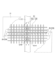
- FIG. 2 is a view taken along the line II-II in FIG. 1.
- a part of the concrete 51 and the deck plate 53 are shown transparently.
- the reinforcing reinforcing bars 52 buried in the concrete 51 of the concrete floor slab 5 are not arranged over both of the small beams 2A and 2B.
- the reinforcing reinforcing bars 52A arranged above the small beam 2A have a terminal end 521A above the large beam 1, and do not extend above the small beam 2B.
- the reinforcing reinforcing bars 52B arranged above the small beam 2B also have a terminal end 521B above the large beam 1, and do not extend above the small beam 2A.
- the reinforcing reinforcing bars 52 refer to reinforcing bars arranged for reinforcement near the joint structure of the large beam 1 and the small beams 2A, 2B where tensile force acts on the concrete floor slab 5. Therefore, other reinforcing bars included in the concrete floor slab 5, such as welded wire mesh for preventing crack expansion, which are evenly distributed over the entire surface of the concrete floor slab 5, are arranged over both of the small beams 2A and 2B. You can. Welded wire mesh to prevent crack expansion, which is placed evenly over the entire surface of the concrete floor slab 5, can also contribute to improving the rigidity of the joint, but with only welded wire mesh, the strength of the joint is insufficient to withstand the moment generated at the end of the beam.
- reinforcing reinforcing bars 52 As the welded wire mesh for preventing crack expansion, which is arranged evenly over the entire surface of the concrete floor slab 5, a wire mesh with a wire diameter of 6 mm and a mesh size of 100 mm, or a deformed reinforcing bar with a wire diameter of 10 mm and a mesh size of 200 mm is exemplified.
- Examples of reinforcing reinforcing bars include ones with a nominal diameter of 10 to 16 mm and a pitch of 100 to 200 mm, arranged in one direction rather than in a mesh pattern, but are not limited to these examples.
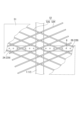
- FIG. 3 is a diagram showing a first modification of the joining structure according to the first embodiment of the present invention.
- the reinforcing reinforcing bars 52 include reinforcing reinforcing bars 52C and 52D that have portions extending in a direction oblique to the material axis directions of the small beams 2A and 2B.
- the reinforcing reinforcing bars 52C extend above the small beam 2A in a direction oblique to the material axis direction of the small beam 2A, and are folded back toward the small beam 2A at a folded portion 522A above the main beam 1.
- the reinforcing reinforcing bars 52D extend above the small beam 2B in a direction oblique to the material axis direction of the small beam 2B, and are folded back toward the small beam 2B at a folded portion 522B above the large beam 1.
- the reinforcing reinforcing bars 52 buried in the concrete 51 of the concrete floor slab 5 are not placed over both of the small beams 2A and 2B.
- FIG. 4 is a diagram showing a second modification of the joining structure according to the first embodiment of the present invention.
- the reinforcing reinforcing bars 52 include reinforcing reinforcing bars 52E, 52F having portions extending in a direction oblique to the material axis direction of the small beams 2A, 2B.
- the reinforcing reinforcing bar 52E extends above the small beam 2A in a direction oblique to the material axis direction of the small beam 2A, and has a terminal end 521A above the main beam 1.
- the reinforcing reinforcing bar 52F extends above the small beam 2B in a direction oblique to the material axis direction of the small beam 2B, and has a terminal end 521B above the main beam 1. Accordingly, in the example of FIG. 4 as well, the reinforcing reinforcing bars 52 buried in the concrete 51 of the concrete floor slab 5 are not placed over both of the small beams 2A and 2B. As in the illustrated example, the reinforcing reinforcing bars 52E and 52F are folded back at the folded parts 523A and 523B on the side of the small beam 2A or the side of the small beam 2B, and are arranged so that both end portions are located above the main beam 1. may be done.
- the reinforcing reinforcing bars 52 buried in the concrete 51 of the concrete floor slab 5 are not placed above both the small beams 2A and 2B, so they are placed on the small beam 2A side with the large beam 1 as the boundary, or on the small beam 2A side or the small beam Reinforcement work can be performed independently in any section on the 2B side. In this case, for example, while work such as laying deck plates is being performed in one compartment, reinforcement work can be carried out in advance in the other compartment, improving workability.
- this embodiment when this embodiment is applied to a concrete floor slab using a deck with truss bars, for example, the reinforcing bars are stored in advance under the top reinforcement of the truss bars, and the reinforcing bars are placed adjacent to the deck after the deck with truss bars is laid. It becomes possible to place reinforcement by sliding it toward the span. As a result, even if it is difficult to secure the necessary concrete cover thickness by layering reinforcing reinforcing bars on top of the top end reinforcement, the cover thickness can be ensured.
- FIG. 5 is a diagram showing a joining structure according to another example.
- reinforcing reinforcing bars 52 embedded in concrete 51 in concrete floor slab 5 include reinforcing reinforcing bars 52G and 52H extending in directions oblique to beams 2A and 2B, respectively.
- reinforcing reinforcing bars 52G and 52H extending in directions oblique to beams 2A and 2B, respectively.
- the reinforcing reinforcing bars When the reinforcing reinforcing bars extend in a direction oblique to the material axis of the small beam as in the examples shown in Figures 3 to 5, the component force in the material axis direction of the small beam 2 out of the tensile force of the reinforcing reinforcing bar is Contributes to rotational restraint at the end. Therefore, in order to ensure this component force, the reinforcing reinforcing bars should be placed at an angle that is not perpendicular to the axis of the beam, for example, at an angle of 70 degrees or less on the acute angle side with respect to the axis of the beam. It is desirable that it extends to .
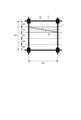
- FIGS. 6 and 7 are diagrams for further explaining the angle when the reinforcing reinforcing bars extend in a direction oblique to the material axis direction of the small beam, as in the examples shown in FIGS. 3 to 5.
- the concrete floor slab is supported in rectangular areas bounded by a girder 1 and at least one sub-beam 2 .
- the intersection of the beams is the mountain, and the point directly above the beam is the ridgeline, and the concrete floor slab is formed at the intersection of the diagonals of each rectangle. It flexes greatly depending on the position.
- reinforcing reinforcing bars extend diagonally to each rectangle.
- the rectangular area surrounded by the main beam 1, primary beam 2P, and secondary beam 2Q is the primary beam 2P.
- the length of the side along is 3 m, and the length of the side perpendicular to the primary beam 2P is 7.5 m.
- the angle ⁇ 2 between the extending direction of the reinforcing reinforcing bars 52 and the material axis direction of the primary beam 2P is tan ⁇ 1 (7 .5/3) ⁇ 68.2 degrees.
- the reinforcing reinforcing bars extend in a direction diagonal to the material axis direction of the small beam, the reinforcing reinforcing bars
- the angle between the extending direction and the material axis direction of the small beam is preferably 10 degrees or more and 70 degrees or less.
- FIG. 6 is a diagram showing a joining structure according to a second embodiment of the present invention.
- a tension member 7 is further arranged in the same joint structure as in the first embodiment described above, which is formed between the large beam 1 and the small beams 2A and 2B.
- the tension member 7 has one end secured to a perforated plate 71A joined to the web 21A of the beam 2A and the upper flange 22A using a nut 72A, and the other end secured to the web 21B of the beam 2B and the perforated plate 71A joined to the upper flange 22A. It is locked to a perforated plate 71B joined to the upper flange 22B using a nut 72B.
- the tension member 7 is arranged to pass through a through hole 111 formed in the web 11 of the girder 1, and transmits the tensile force acting on each of the small beams 2A and 2B without going through the girder 1.
- the tension member 7 is illustrated as a steel rod with threaded ends, the entire length may be threaded.
- the tension member 7 may be anchored to the perforated plate at one end with a pre-welded flange, and only the other end may be threaded and anchored to the perforated plate using a nut.
- the tensile member 7 by arranging the tensile member 7, the tensile force acting on the small beams 2A and 2B can be transmitted without relying on the reinforcing bars in the concrete floor slab 5. Therefore, even if the reinforcing reinforcing bars 52 buried in the concrete 51 of the concrete floor slab 5 are not placed over both the small beams 2A and 2B as described in the first embodiment, the joint structure is sufficient. It becomes easy to ensure stress transmission performance.
- Such a configuration of the tension member 7 is applicable, for example, to each of the examples described above with reference to FIGS. 1 to 5.
- the amount of reinforcement reinforcing bars can be increased by arranging the tension member 7 to transmit the tensile force. It is possible to secure cover thickness and improve workability.
- the perforated plates 71A, 71B are connected to both the upper flanges 22A, 22B and the webs 21A, 21B at the small beams 2A, 2B, respectively.
- 71B may be joined only to either the upper flanges 22A, 22B or the webs 21A, 21B.
- FIG. 7 is a diagram showing a modification of the joining structure according to the second embodiment of the present invention.
- tension members 7A and 7B are arranged separately on both sides of the girder 1 and are locked to the small beams 2A and 2B and the girder 1, respectively.
- the tension member 7A has one end secured to the perforated plate 71A on the small beam 2A side using a nut 72A, and the other end secured to the upper flange 12 of the main beam 1 and the gusset plate 31A. It is locked to the joined perforated plate 73A using a nut 74A.
- one end of the tension member 7B was locked to the perforated plate 71B on the side of the small beam 2B using a nut 72B, and the other end was joined to the upper flange 12 of the main beam 1 and the gusset plate 31B. It is locked to the perforated plate 73B using a nut 74B. Note that the perforated plates 73A and 73B on the side of the girder 1 may be joined to only one of the upper flange 12 and the gusset plates 31A and 31B.
- the members are independent on each side of the small beams 2A and 2B, there is one small beam extending in the direction intersecting the large beam 1 on one side of the large beam 1. It is also applicable when only books are placed.
- the joint structure connects the large beam 1 and the small beam 2A
- the concrete floor slab 5 is constructed above the large beam 1 and the small beam 2A, and the web of the small beam 2A is connected to the large beam 1 through the gusset plate 31A.
- a tension member 7A may be disposed that is joined and locked to the upper flange 22A or web 21A of the small beam 2A and the large beam 1, respectively.
- the tension member 7A may be locked to the perforated plate 73A on the girder 1 side using a nut 74 or the like, or it may be secured to the perforated plate 73A on the girder 1 side using a nut 74 or the like, or it may be formed in the web 11 of the girder 1 in the same way as the through hole 111 shown in FIG. It may be locked in the through hole using a nut 74 or the like.
- a tensile force is introduced into the tension member 7 (or tension members 7A, 7B) after the concrete 51 of the concrete floor slab 5 has hardened in the construction process of the joint structure.
- prestress can be introduced into the negative bending region of the concrete 51. This can prevent the concrete 51 from cracking when a live load is applied to the concrete floor slab 5.
- FIG. 8 is a diagram showing a first modification of the joint structure on the lower flange side of the beam.
- the lower flange 23A of the small beam 2A is bolted to the rib 32A via splice plates 42A, 43A attached to both sides.
- the lower flange 23B of the small beam 2B is bolted to the rib 32B via splice plates 42B and 43B.
- the lower flanges 23A, 23B of the small beams 2A, 2B are joined to the joining members on the large beam 1 side, such as the ribs 32A, 32B, not only by metal touch connection but also by bolt connection, and from the lower flanges 23A, 23B to the large beam 1 side.
- a compressive force may be transmitted to.
- FIG. 9 is a diagram showing a second modification of the joint structure on the lower flange side of the beam.
- gusset plates 31A and 31B are arranged as joining members, but no ribs are arranged, and the lower flanges 23A and 23B of the small beams 2A and 2B are not joined to the joining member on the large beam 1 side.
- reinforcing plates 33A, 33B are arranged in contact with the side end surfaces of gusset plates 31A, 31B below the height centers of webs 21A, 21B, and reinforcing plates 33A, 33B are connected to the webs of beams 2A, 2B, respectively. It is bolted to 21A and 21B.
- the side end surfaces of the gusset plates 31A, 31B are end surfaces facing the material axis direction of the small beams 2A, 2B.
- the joint structure on the lower flange side of the small beam in the embodiment of the present invention is not limited to the example described above, and any configuration is possible.
- the reinforcing plates 33A and 33B may not be arranged, and the concrete floor slab 5 may be added to a simple pin joint. Even in this case, in addition to the shear forces in the beams transmitted by the pin connection, the tensile forces acting on the beam upper flanges are transmitted through the concrete floor slab or tension members, so that stress transmission in the joint structure is reduced. Performance will improve.
- Tension member 71A, 71B, 73A, 73B... Perforated plate, 72A , 72B, 74A, 74B...Nut, 521A, 521B...Terminal end, 522A, 522B, 523A, 523B...Folded part.
Landscapes
- Engineering & Computer Science (AREA)
- Architecture (AREA)
- Physics & Mathematics (AREA)
- Electromagnetism (AREA)
- Civil Engineering (AREA)
- Structural Engineering (AREA)
- Joining Of Building Structures In Genera (AREA)
Priority Applications (1)
| Application Number | Priority Date | Filing Date | Title |
|---|---|---|---|
| JP2023541969A JP7502710B2 (ja) | 2022-03-25 | 2023-03-22 | 接合構造および接合構造の構築方法 |
Applications Claiming Priority (2)
| Application Number | Priority Date | Filing Date | Title |
|---|---|---|---|
| JP2022-050110 | 2022-03-25 | ||
| JP2022050110 | 2022-03-25 |
Publications (1)
| Publication Number | Publication Date |
|---|---|
| WO2023182318A1 true WO2023182318A1 (ja) | 2023-09-28 |
Family
ID=88101105
Family Applications (1)
| Application Number | Title | Priority Date | Filing Date |
|---|---|---|---|
| PCT/JP2023/011058 Ceased WO2023182318A1 (ja) | 2022-03-25 | 2023-03-22 | 接合構造および接合構造の構築方法 |
Country Status (2)
| Country | Link |
|---|---|
| JP (1) | JP7502710B2 (https=) |
| WO (1) | WO2023182318A1 (https=) |
Citations (7)
| Publication number | Priority date | Publication date | Assignee | Title |
|---|---|---|---|---|
| JPS5340247B2 (https=) * | 1975-04-30 | 1978-10-26 | ||
| JP2007032072A (ja) * | 2005-07-26 | 2007-02-08 | Ando Corp | 鉄骨梁の接続構造 |
| JP2007309020A (ja) * | 2006-05-19 | 2007-11-29 | Sumitomo Metal Ind Ltd | 鉄骨片持ち梁と鉄骨小梁の接合構造 |
| JP2015068001A (ja) * | 2013-09-27 | 2015-04-13 | 川田工業株式会社 | 鉄骨梁の仕口構造 |
| JP2019206812A (ja) * | 2018-05-28 | 2019-12-05 | 株式会社錢高組 | スラブ支持構造 |
| JP6631679B1 (ja) * | 2018-11-12 | 2020-01-15 | 日本製鉄株式会社 | 接合構造 |
| JP2022173695A (ja) * | 2021-05-10 | 2022-11-22 | 株式会社淺沼組 | 小梁端部の接合構造 |
Family Cites Families (1)
| Publication number | Priority date | Publication date | Assignee | Title |
|---|---|---|---|---|
| JP4728729B2 (ja) * | 2005-07-27 | 2011-07-20 | 新日本製鐵株式会社 | 大梁と小梁の高力ボルト接合施工方法と接合構造 |
-
2023
- 2023-03-22 JP JP2023541969A patent/JP7502710B2/ja active Active
- 2023-03-22 WO PCT/JP2023/011058 patent/WO2023182318A1/ja not_active Ceased
Patent Citations (7)
| Publication number | Priority date | Publication date | Assignee | Title |
|---|---|---|---|---|
| JPS5340247B2 (https=) * | 1975-04-30 | 1978-10-26 | ||
| JP2007032072A (ja) * | 2005-07-26 | 2007-02-08 | Ando Corp | 鉄骨梁の接続構造 |
| JP2007309020A (ja) * | 2006-05-19 | 2007-11-29 | Sumitomo Metal Ind Ltd | 鉄骨片持ち梁と鉄骨小梁の接合構造 |
| JP2015068001A (ja) * | 2013-09-27 | 2015-04-13 | 川田工業株式会社 | 鉄骨梁の仕口構造 |
| JP2019206812A (ja) * | 2018-05-28 | 2019-12-05 | 株式会社錢高組 | スラブ支持構造 |
| JP6631679B1 (ja) * | 2018-11-12 | 2020-01-15 | 日本製鉄株式会社 | 接合構造 |
| JP2022173695A (ja) * | 2021-05-10 | 2022-11-22 | 株式会社淺沼組 | 小梁端部の接合構造 |
Also Published As
| Publication number | Publication date |
|---|---|
| JPWO2023182318A1 (https=) | 2023-09-28 |
| JP7502710B2 (ja) | 2024-06-19 |
Similar Documents
| Publication | Publication Date | Title |
|---|---|---|
| US20040128939A1 (en) | Composite bearing deck comprising deck panel and concrete | |
| JP2008063803A (ja) | 内リブ付形鋼を用いた合成床版、合成床版橋又は合成桁橋 | |
| JP2022025804A (ja) | 梁接合構造、建築物 | |
| JP2000355906A (ja) | 波形鋼板ウェブpc箱桁橋における波形鋼板とコンクリート床版の接合部構造 | |
| JP2019189998A (ja) | コンクリート床構造および構造物 | |
| WO2023182318A1 (ja) | 接合構造および接合構造の構築方法 | |
| JP7127350B2 (ja) | 柱梁接合構造、および柱梁接合構造の施工方法 | |
| JP7328610B1 (ja) | 接合構造 | |
| KR101149034B1 (ko) | 보의 휨응력을 향상시킨 조립식 건축물의 연결부재 | |
| JP4644146B2 (ja) | Pc箱桁橋 | |
| KR102564471B1 (ko) | 와렌트러스 형상으로 조립된 합성 격자거더 교량 | |
| JP7434067B2 (ja) | 鉄骨造建物 | |
| JP7580207B2 (ja) | 柱梁架構 | |
| JP2024048567A (ja) | 大梁と小梁の接合構造 | |
| JP3950747B2 (ja) | 橋桁 | |
| JP7390993B2 (ja) | 梁接合構造、及び建築物 | |
| EP3480376B1 (en) | Flooring system | |
| JP7364510B2 (ja) | 床構造 | |
| JP7594978B2 (ja) | 建物 | |
| JP2021130907A (ja) | トラス梁 | |
| JP7477038B2 (ja) | 接続構造 | |
| JP7610500B2 (ja) | 複数の柱梁仕口部を埋設したキャピタルを有する建物構造 | |
| JP3950748B2 (ja) | 橋桁 | |
| JP7761528B2 (ja) | 建物の床構造及び建物 | |
| JP7827556B2 (ja) | 増築工法及び増築構造 |
Legal Events
| Date | Code | Title | Description |
|---|---|---|---|
| WWE | Wipo information: entry into national phase |
Ref document number: 2023541969 Country of ref document: JP |
|
| 121 | Ep: the epo has been informed by wipo that ep was designated in this application |
Ref document number: 23774913 Country of ref document: EP Kind code of ref document: A1 |
|
| WWE | Wipo information: entry into national phase |
Ref document number: 11202404216W Country of ref document: SG |
|
| NENP | Non-entry into the national phase |
Ref country code: DE |
|
| 122 | Ep: pct application non-entry in european phase |
Ref document number: 23774913 Country of ref document: EP Kind code of ref document: A1 |