WO2023182318A1 - Joint structure and method for constructing joint structure - Google Patents
Joint structure and method for constructing joint structure Download PDFInfo
- Publication number
- WO2023182318A1 WO2023182318A1 PCT/JP2023/011058 JP2023011058W WO2023182318A1 WO 2023182318 A1 WO2023182318 A1 WO 2023182318A1 JP 2023011058 W JP2023011058 W JP 2023011058W WO 2023182318 A1 WO2023182318 A1 WO 2023182318A1
- Authority
- WO
- WIPO (PCT)
- Prior art keywords
- beams
- girder
- floor slab
- small
- concrete floor
- Prior art date
Links
- 238000000034 method Methods 0.000 title claims description 7
- 230000003014 reinforcing effect Effects 0.000 claims abstract description 114
- 239000002184 metal Substances 0.000 claims description 4
- 239000000463 material Substances 0.000 description 16
- 238000012986 modification Methods 0.000 description 15
- 230000004048 modification Effects 0.000 description 15
- 238000010586 diagram Methods 0.000 description 14
- 230000002787 reinforcement Effects 0.000 description 11
- 238000005452 bending Methods 0.000 description 5
- 229910000831 Steel Inorganic materials 0.000 description 4
- 238000005336 cracking Methods 0.000 description 4
- 239000010959 steel Substances 0.000 description 4
- 230000005540 biological transmission Effects 0.000 description 3
- 239000002131 composite material Substances 0.000 description 3
- 229910001294 Reinforcing steel Inorganic materials 0.000 description 2
- 230000001154 acute effect Effects 0.000 description 1
- 238000010276 construction Methods 0.000 description 1
- 230000000694 effects Effects 0.000 description 1
- 230000005484 gravity Effects 0.000 description 1
- 230000000149 penetrating effect Effects 0.000 description 1
Images


Classifications
-
- E—FIXED CONSTRUCTIONS
- E04—BUILDING
- E04B—GENERAL BUILDING CONSTRUCTIONS; WALLS, e.g. PARTITIONS; ROOFS; FLOORS; CEILINGS; INSULATION OR OTHER PROTECTION OF BUILDINGS
- E04B1/00—Constructions in general; Structures which are not restricted either to walls, e.g. partitions, or floors or ceilings or roofs
- E04B1/18—Structures comprising elongated load-supporting parts, e.g. columns, girders, skeletons
- E04B1/24—Structures comprising elongated load-supporting parts, e.g. columns, girders, skeletons the supporting parts consisting of metal
-
- E—FIXED CONSTRUCTIONS
- E04—BUILDING
- E04B—GENERAL BUILDING CONSTRUCTIONS; WALLS, e.g. PARTITIONS; ROOFS; FLOORS; CEILINGS; INSULATION OR OTHER PROTECTION OF BUILDINGS
- E04B1/00—Constructions in general; Structures which are not restricted either to walls, e.g. partitions, or floors or ceilings or roofs
- E04B1/38—Connections for building structures in general
- E04B1/58—Connections for building structures in general of bar-shaped building elements
-
- E—FIXED CONSTRUCTIONS
- E04—BUILDING
- E04B—GENERAL BUILDING CONSTRUCTIONS; WALLS, e.g. PARTITIONS; ROOFS; FLOORS; CEILINGS; INSULATION OR OTHER PROTECTION OF BUILDINGS
- E04B5/00—Floors; Floor construction with regard to insulation; Connections specially adapted therefor
- E04B5/16—Load-carrying floor structures wholly or partly cast or similarly formed in situ
- E04B5/32—Floor structures wholly cast in situ with or without form units or reinforcements
- E04B5/36—Floor structures wholly cast in situ with or without form units or reinforcements with form units as part of the floor
- E04B5/38—Floor structures wholly cast in situ with or without form units or reinforcements with form units as part of the floor with slab-shaped form units acting simultaneously as reinforcement; Form slabs with reinforcements extending laterally outside the element
- E04B5/40—Floor structures wholly cast in situ with or without form units or reinforcements with form units as part of the floor with slab-shaped form units acting simultaneously as reinforcement; Form slabs with reinforcements extending laterally outside the element with metal form-slabs
Definitions
- the present invention relates to a joining structure and a method of constructing a joining structure.
- Beam end connections such as between RC beams or walls and girders, or between girders and sub-beams, are generally designed as rigid or pin connections.
- the support member is a large beam
- the upper and lower flanges of the small beam are welded or bolted to the large beam, and the web of the small beam is bolted to the large beam.
- the web of the small beam is bolted to the fin plate (also called shear plate, gusset plate, etc.) attached to the main beam, and the upper and lower flanges of the small beam are not connected to the main beam.
- Non-Patent Document 1 there is a gravity frame that does not bear horizontal force, a moment frame that does not cause antisymmetrical bending when the horizontal force is small, and the beam and floor under load conditions where the moment at the joint does not reverse.
- a composite structure in which the slab is integrated with a shear connector is described.
- the rigidity of the joint can be easily increased.
- EUROPEAN COMMITTEE FOR STANDARDIZATION “Eurocode 4: Design of composite steel and concrete structures Part 1-1: General rules and rules for buildings”, April 2009
- reinforcing reinforcing bars that span the large beam are used to mutually transmit the tensile force acting on the upper flange sides of the small beams connected to both sides of the large beam.
- reinforcing bars could only be placed after other reinforcing bars had been placed in the sections on both sides of the girder, which caused problems in terms of workability.
- the vertical load supported by the floor slab creates a negative bending region in the floor slab around the joint between the large beam and the small beam, where tensile force acts on the slab.
- reinforcing steel bars in floor slabs resist tensile forces, but concrete has low resistance to tensile forces and is prone to cracking.
- reinforcing bars are placed along the axis of the beam, although the reinforcing bars contribute to reinforcing joints, their contribution to the direction of maximum deflection of the floor slab is limited. However, the effect was insufficient in terms of suppressing deflection and cracking of the floor slab.
- the present invention provides a joint structure in which a large beam and a small beam upper flange are joined via a concrete floor slab, and which can improve workability while ensuring the concrete cover thickness of the floor slab.
- the purpose of the present invention is to provide a method for constructing a joint structure that can prevent cracks in slabs.
- a girder having an H-shaped cross section, first and second small beams having an H-shaped cross section and extending in a direction intersecting the girder, the ends of which are opposite to each other with the girder in between, and first and second joining members that respectively join the webs of the first and second small beams to the main beam, wherein a concrete floor is provided above the main beam and the first and second small beams.
- a slab is constructed, wherein the upper flanges of the first and second crossbeams are respectively joined to the concrete floor slab and not directly joined to the girder and the first and second joint members; A joint structure in which reinforcing reinforcing bars embedded in concrete in a concrete floor slab are not placed above both the first and second beams.
- a slab is constructed, wherein the upper flanges of the first and second crossbeams are respectively joined to the concrete floor slab and not directly joined to the girder and the first and second joint members;
- the reinforcing reinforcing bars embedded in the concrete of the concrete floor slab have a joint structure in which at least a portion thereof extends in a direction obliquely intersecting the axis directions of the first and second beams.
- a concrete floor slab is constructed above the girder and the small beam, and the upper flange of the small beam is joined to the concrete floor slab and is not directly connected to the girder and the connecting member, but is connected to the small beam.
- the joint structure further comprises a tension member respectively locked to an upper flange or web of the beam and an upper flange or web of the girder.
- a girder having an H-shaped cross section, first and second small beams having an H-shaped cross section and extending in a direction intersecting the girder, the ends of which are opposite to each other across the girder, and and first and second joining members that respectively join the webs of the first and second small beams to the main beam, wherein a concrete floor is provided above the main beam and the first and second small beams.
- a slab is constructed, wherein the upper flanges of the first and second crossbeams are respectively joined to the concrete floor slab and not directly joined to the girder and the first and second joint members;
- the joining structure further includes a tension member that is respectively locked to the upper flanges or webs of each of the first and second small beams and passes through a through hole formed in the web of the large beam.
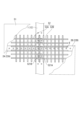
- FIG. 1 is a diagram showing a joining structure according to a first embodiment of the present invention.
- FIG. 2 is a view taken along the line II-II in FIG. 1.
- FIG. It is a figure which shows the 1st modification of the joining structure based on the 1st Embodiment of this invention. It is a figure which shows the 2nd modification of the joining structure based on the 1st Embodiment of this invention.
- FIG. 7 is a diagram showing a joining structure according to another example.
- FIG. 6 is a diagram for explaining an angle when reinforcing reinforcing bars extend in a direction obliquely intersecting the material axis direction of a small beam.
- FIG. 6 is a diagram for explaining an angle when reinforcing reinforcing bars extend in a direction obliquely intersecting the material axis direction of a small beam.
- FIG. 7 is a diagram showing a joining structure according to a second embodiment of the present invention. It is a figure which shows the modification of the joining structure based on the 2nd Embodiment of this invention. It is a figure which shows the 1st modification of the joint structure by the side of a small beam lower flange. It is a figure which shows the 2nd modification of the joint structure on the side of a small beam lower flange.
- FIG. 1 is a diagram showing a joining structure according to a first embodiment of the present invention.
- the joint structure according to this embodiment is formed between a large beam 1 and small beams 2A and 2B.
- the main beam 1 and the small beams 2A, 2B are each made of H-beam steel, the large beam 1 has a web 11, an upper flange 12, and a lower flange 13, and the small beams 2A, 2B have webs 21A, 21B, an upper flange 22A, 22B and lower flanges 23A, 23B.
- the large beam 1 and the small beams 2A, 2B are not limited to H-shaped steel as long as they have an H-shaped cross section, and may be made of welded members having an H-shaped cross section, for example.
- gusset plates 31A, 31B and ribs 32A, 32B are arranged as joining members.
- the gusset plates 31A, 31B are welded to the web 11 and the upper flange 12 of the girder 1, and the ribs 32A, 32B are welded to the gusset plates 31A, 31B and the web 11 of the girder 1.
- the web 21A of the beam 2A is bolted to the gusset plate 31A, and the web 21B of the beam 2B is bolted to the gusset plate 31B.
- the lower flange 23A of the small beam 2A is metal-touch bonded to the rib 32A via the contact member 41A
- the lower flange 23B of the small beam 2B is metal-touch bonded to the rib 32B via the contact member 41B.
- the contact members 41A and 41B are not limited to the illustrated example, and various contact members such as those described in, for example, Japanese Patent No. 6635175 and Japanese Patent No. 6631679 can be used.
- a concrete floor slab 5 is constructed above the girder 1 and the small beams 2A, 2B.
- the concrete floor slab 5 is a deck composite slab and includes concrete 51, reinforcing steel bars 52, and a deck plate 53.
- the concrete floor slab 5 may include reinforcing bars other than the reinforcing reinforcing bars 52. Studs 6 are erected on the upper flanges 12, 22A, 22B of the main beam 1 and the small beams 2A, 2B, penetrating the deck plate 53, and the studs 6 are fixed to the concrete 51.
- the beams 2A, 2B are connected to the concrete floor slab 5, and thereby the tensile force acting on the upper flanges 22A, 22B of the beams 2A, 2B is transmitted to the concrete floor slab 5.
- the upper flanges 22A and 22B are not directly joined to the girder 1 and the gusset plates 31A and 31B.
- FIG. 2 is a view taken along the line II-II in FIG. 1.
- a part of the concrete 51 and the deck plate 53 are shown transparently.
- the reinforcing reinforcing bars 52 buried in the concrete 51 of the concrete floor slab 5 are not arranged over both of the small beams 2A and 2B.
- the reinforcing reinforcing bars 52A arranged above the small beam 2A have a terminal end 521A above the large beam 1, and do not extend above the small beam 2B.
- the reinforcing reinforcing bars 52B arranged above the small beam 2B also have a terminal end 521B above the large beam 1, and do not extend above the small beam 2A.
- the reinforcing reinforcing bars 52 refer to reinforcing bars arranged for reinforcement near the joint structure of the large beam 1 and the small beams 2A, 2B where tensile force acts on the concrete floor slab 5. Therefore, other reinforcing bars included in the concrete floor slab 5, such as welded wire mesh for preventing crack expansion, which are evenly distributed over the entire surface of the concrete floor slab 5, are arranged over both of the small beams 2A and 2B. You can. Welded wire mesh to prevent crack expansion, which is placed evenly over the entire surface of the concrete floor slab 5, can also contribute to improving the rigidity of the joint, but with only welded wire mesh, the strength of the joint is insufficient to withstand the moment generated at the end of the beam.
- reinforcing reinforcing bars 52 As the welded wire mesh for preventing crack expansion, which is arranged evenly over the entire surface of the concrete floor slab 5, a wire mesh with a wire diameter of 6 mm and a mesh size of 100 mm, or a deformed reinforcing bar with a wire diameter of 10 mm and a mesh size of 200 mm is exemplified.
- Examples of reinforcing reinforcing bars include ones with a nominal diameter of 10 to 16 mm and a pitch of 100 to 200 mm, arranged in one direction rather than in a mesh pattern, but are not limited to these examples.
- FIG. 3 is a diagram showing a first modification of the joining structure according to the first embodiment of the present invention.
- the reinforcing reinforcing bars 52 include reinforcing reinforcing bars 52C and 52D that have portions extending in a direction oblique to the material axis directions of the small beams 2A and 2B.
- the reinforcing reinforcing bars 52C extend above the small beam 2A in a direction oblique to the material axis direction of the small beam 2A, and are folded back toward the small beam 2A at a folded portion 522A above the main beam 1.
- the reinforcing reinforcing bars 52D extend above the small beam 2B in a direction oblique to the material axis direction of the small beam 2B, and are folded back toward the small beam 2B at a folded portion 522B above the large beam 1.
- the reinforcing reinforcing bars 52 buried in the concrete 51 of the concrete floor slab 5 are not placed over both of the small beams 2A and 2B.
- FIG. 4 is a diagram showing a second modification of the joining structure according to the first embodiment of the present invention.
- the reinforcing reinforcing bars 52 include reinforcing reinforcing bars 52E, 52F having portions extending in a direction oblique to the material axis direction of the small beams 2A, 2B.
- the reinforcing reinforcing bar 52E extends above the small beam 2A in a direction oblique to the material axis direction of the small beam 2A, and has a terminal end 521A above the main beam 1.
- the reinforcing reinforcing bar 52F extends above the small beam 2B in a direction oblique to the material axis direction of the small beam 2B, and has a terminal end 521B above the main beam 1. Accordingly, in the example of FIG. 4 as well, the reinforcing reinforcing bars 52 buried in the concrete 51 of the concrete floor slab 5 are not placed over both of the small beams 2A and 2B. As in the illustrated example, the reinforcing reinforcing bars 52E and 52F are folded back at the folded parts 523A and 523B on the side of the small beam 2A or the side of the small beam 2B, and are arranged so that both end portions are located above the main beam 1. may be done.
- the reinforcing reinforcing bars 52 buried in the concrete 51 of the concrete floor slab 5 are not placed above both the small beams 2A and 2B, so they are placed on the small beam 2A side with the large beam 1 as the boundary, or on the small beam 2A side or the small beam Reinforcement work can be performed independently in any section on the 2B side. In this case, for example, while work such as laying deck plates is being performed in one compartment, reinforcement work can be carried out in advance in the other compartment, improving workability.
- this embodiment when this embodiment is applied to a concrete floor slab using a deck with truss bars, for example, the reinforcing bars are stored in advance under the top reinforcement of the truss bars, and the reinforcing bars are placed adjacent to the deck after the deck with truss bars is laid. It becomes possible to place reinforcement by sliding it toward the span. As a result, even if it is difficult to secure the necessary concrete cover thickness by layering reinforcing reinforcing bars on top of the top end reinforcement, the cover thickness can be ensured.
- FIG. 5 is a diagram showing a joining structure according to another example.
- reinforcing reinforcing bars 52 embedded in concrete 51 in concrete floor slab 5 include reinforcing reinforcing bars 52G and 52H extending in directions oblique to beams 2A and 2B, respectively.
- reinforcing reinforcing bars 52G and 52H extending in directions oblique to beams 2A and 2B, respectively.
- the reinforcing reinforcing bars When the reinforcing reinforcing bars extend in a direction oblique to the material axis of the small beam as in the examples shown in Figures 3 to 5, the component force in the material axis direction of the small beam 2 out of the tensile force of the reinforcing reinforcing bar is Contributes to rotational restraint at the end. Therefore, in order to ensure this component force, the reinforcing reinforcing bars should be placed at an angle that is not perpendicular to the axis of the beam, for example, at an angle of 70 degrees or less on the acute angle side with respect to the axis of the beam. It is desirable that it extends to .
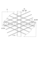
- FIGS. 6 and 7 are diagrams for further explaining the angle when the reinforcing reinforcing bars extend in a direction oblique to the material axis direction of the small beam, as in the examples shown in FIGS. 3 to 5.
- the concrete floor slab is supported in rectangular areas bounded by a girder 1 and at least one sub-beam 2 .
- the intersection of the beams is the mountain, and the point directly above the beam is the ridgeline, and the concrete floor slab is formed at the intersection of the diagonals of each rectangle. It flexes greatly depending on the position.
- reinforcing reinforcing bars extend diagonally to each rectangle.
- the rectangular area surrounded by the main beam 1, primary beam 2P, and secondary beam 2Q is the primary beam 2P.
- the length of the side along is 3 m, and the length of the side perpendicular to the primary beam 2P is 7.5 m.
- the angle ⁇ 2 between the extending direction of the reinforcing reinforcing bars 52 and the material axis direction of the primary beam 2P is tan ⁇ 1 (7 .5/3) ⁇ 68.2 degrees.
- the reinforcing reinforcing bars extend in a direction diagonal to the material axis direction of the small beam, the reinforcing reinforcing bars
- the angle between the extending direction and the material axis direction of the small beam is preferably 10 degrees or more and 70 degrees or less.
- FIG. 6 is a diagram showing a joining structure according to a second embodiment of the present invention.
- a tension member 7 is further arranged in the same joint structure as in the first embodiment described above, which is formed between the large beam 1 and the small beams 2A and 2B.
- the tension member 7 has one end secured to a perforated plate 71A joined to the web 21A of the beam 2A and the upper flange 22A using a nut 72A, and the other end secured to the web 21B of the beam 2B and the perforated plate 71A joined to the upper flange 22A. It is locked to a perforated plate 71B joined to the upper flange 22B using a nut 72B.
- the tension member 7 is arranged to pass through a through hole 111 formed in the web 11 of the girder 1, and transmits the tensile force acting on each of the small beams 2A and 2B without going through the girder 1.
- the tension member 7 is illustrated as a steel rod with threaded ends, the entire length may be threaded.
- the tension member 7 may be anchored to the perforated plate at one end with a pre-welded flange, and only the other end may be threaded and anchored to the perforated plate using a nut.
- the tensile member 7 by arranging the tensile member 7, the tensile force acting on the small beams 2A and 2B can be transmitted without relying on the reinforcing bars in the concrete floor slab 5. Therefore, even if the reinforcing reinforcing bars 52 buried in the concrete 51 of the concrete floor slab 5 are not placed over both the small beams 2A and 2B as described in the first embodiment, the joint structure is sufficient. It becomes easy to ensure stress transmission performance.
- Such a configuration of the tension member 7 is applicable, for example, to each of the examples described above with reference to FIGS. 1 to 5.
- the amount of reinforcement reinforcing bars can be increased by arranging the tension member 7 to transmit the tensile force. It is possible to secure cover thickness and improve workability.
- the perforated plates 71A, 71B are connected to both the upper flanges 22A, 22B and the webs 21A, 21B at the small beams 2A, 2B, respectively.
- 71B may be joined only to either the upper flanges 22A, 22B or the webs 21A, 21B.
- FIG. 7 is a diagram showing a modification of the joining structure according to the second embodiment of the present invention.
- tension members 7A and 7B are arranged separately on both sides of the girder 1 and are locked to the small beams 2A and 2B and the girder 1, respectively.
- the tension member 7A has one end secured to the perforated plate 71A on the small beam 2A side using a nut 72A, and the other end secured to the upper flange 12 of the main beam 1 and the gusset plate 31A. It is locked to the joined perforated plate 73A using a nut 74A.
- one end of the tension member 7B was locked to the perforated plate 71B on the side of the small beam 2B using a nut 72B, and the other end was joined to the upper flange 12 of the main beam 1 and the gusset plate 31B. It is locked to the perforated plate 73B using a nut 74B. Note that the perforated plates 73A and 73B on the side of the girder 1 may be joined to only one of the upper flange 12 and the gusset plates 31A and 31B.
- the members are independent on each side of the small beams 2A and 2B, there is one small beam extending in the direction intersecting the large beam 1 on one side of the large beam 1. It is also applicable when only books are placed.
- the joint structure connects the large beam 1 and the small beam 2A
- the concrete floor slab 5 is constructed above the large beam 1 and the small beam 2A, and the web of the small beam 2A is connected to the large beam 1 through the gusset plate 31A.
- a tension member 7A may be disposed that is joined and locked to the upper flange 22A or web 21A of the small beam 2A and the large beam 1, respectively.
- the tension member 7A may be locked to the perforated plate 73A on the girder 1 side using a nut 74 or the like, or it may be secured to the perforated plate 73A on the girder 1 side using a nut 74 or the like, or it may be formed in the web 11 of the girder 1 in the same way as the through hole 111 shown in FIG. It may be locked in the through hole using a nut 74 or the like.
- a tensile force is introduced into the tension member 7 (or tension members 7A, 7B) after the concrete 51 of the concrete floor slab 5 has hardened in the construction process of the joint structure.
- prestress can be introduced into the negative bending region of the concrete 51. This can prevent the concrete 51 from cracking when a live load is applied to the concrete floor slab 5.
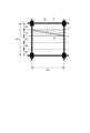
- FIG. 8 is a diagram showing a first modification of the joint structure on the lower flange side of the beam.
- the lower flange 23A of the small beam 2A is bolted to the rib 32A via splice plates 42A, 43A attached to both sides.
- the lower flange 23B of the small beam 2B is bolted to the rib 32B via splice plates 42B and 43B.
- the lower flanges 23A, 23B of the small beams 2A, 2B are joined to the joining members on the large beam 1 side, such as the ribs 32A, 32B, not only by metal touch connection but also by bolt connection, and from the lower flanges 23A, 23B to the large beam 1 side.
- a compressive force may be transmitted to.
- FIG. 9 is a diagram showing a second modification of the joint structure on the lower flange side of the beam.
- gusset plates 31A and 31B are arranged as joining members, but no ribs are arranged, and the lower flanges 23A and 23B of the small beams 2A and 2B are not joined to the joining member on the large beam 1 side.
- reinforcing plates 33A, 33B are arranged in contact with the side end surfaces of gusset plates 31A, 31B below the height centers of webs 21A, 21B, and reinforcing plates 33A, 33B are connected to the webs of beams 2A, 2B, respectively. It is bolted to 21A and 21B.
- the side end surfaces of the gusset plates 31A, 31B are end surfaces facing the material axis direction of the small beams 2A, 2B.
- the joint structure on the lower flange side of the small beam in the embodiment of the present invention is not limited to the example described above, and any configuration is possible.
- the reinforcing plates 33A and 33B may not be arranged, and the concrete floor slab 5 may be added to a simple pin joint. Even in this case, in addition to the shear forces in the beams transmitted by the pin connection, the tensile forces acting on the beam upper flanges are transmitted through the concrete floor slab or tension members, so that stress transmission in the joint structure is reduced. Performance will improve.
- Tension member 71A, 71B, 73A, 73B... Perforated plate, 72A , 72B, 74A, 74B...Nut, 521A, 521B...Terminal end, 522A, 522B, 523A, 523B...Folded part.
Abstract
An object of the present invention is to improve workability while ensuring the concrete cover thickness of a floor slab in a joint structure in which a girder and upper flanges of beams are joined with the concrete floor slab interposed therebetween. Provided is a joint structure comprising: a girder having an H-shaped cross section; a first and a second beam that have an H-shaped cross section, extend in a direction intersecting the girder and have end portions facing each other across the girder; and a first and a second joining member that join the webs of the first and second beams, respectively, to the girder, wherein a concrete floor slab is constructed above the girder and the first and second beams, the upper flanges of the first and second beams are each joined to the concrete floor slab and are not directly joined to the girder or the first and second joining members, and reinforcing bars that are embedded in the concrete in the concrete floor slab are not arranged over both the first and second beams.
Description
本発明は、接合構造および接合構造の構築方法に関する。
The present invention relates to a joining structure and a method of constructing a joining structure.
例えばRC梁または壁と大梁との間、または大梁と小梁との間のような梁端接合部は、一般的に剛接合またはピン接合として設計される。支持部材を大梁とした例でいうと、剛接合の場合には小梁の上下フランジを大梁に溶接またはボルト接合し、さらに小梁のウェブを大梁にボルト接合する。ピン接合の場合、小梁のウェブを大梁に取り付けたフィンプレート(シアプレート、ガセットプレート等ともいう)にボルト接合し、小梁の上下フランジは大梁に接合しない。
Beam end connections, such as between RC beams or walls and girders, or between girders and sub-beams, are generally designed as rigid or pin connections. In the example where the support member is a large beam, in the case of rigid connection, the upper and lower flanges of the small beam are welded or bolted to the large beam, and the web of the small beam is bolted to the large beam. In the case of pin connection, the web of the small beam is bolted to the fin plate (also called shear plate, gusset plate, etc.) attached to the main beam, and the upper and lower flanges of the small beam are not connected to the main beam.
これに対して、非特許文献1には、水平力を負担しないグラビティフレームや、水平力が小さく逆対称曲げにならない場合のモーメントフレームなど、接合部のモーメントが逆転しない荷重条件下において梁と床スラブとをシアコネクタで一体化した合成構造が記載されている。この場合、小梁の上フランジは大梁に直接的には接合されないが、床スラブの中の鉄筋を介して引張力が伝達されるため、容易に接合部の剛性を高めることができる。接合部の剛性を高めることによって、梁のたわみや梁中央の曲げモーメントが低減され、設計の余裕度を高めたり、梁断面をより小さくしたりできる。
On the other hand, in Non-Patent Document 1, there is a gravity frame that does not bear horizontal force, a moment frame that does not cause antisymmetrical bending when the horizontal force is small, and the beam and floor under load conditions where the moment at the joint does not reverse. A composite structure in which the slab is integrated with a shear connector is described. In this case, although the upper flange of the small beam is not directly joined to the main beam, tensile force is transmitted through the reinforcing bars in the floor slab, so the rigidity of the joint can be easily increased. By increasing the rigidity of the joint, the deflection of the beam and the bending moment at the center of the beam are reduced, allowing for greater design latitude and making the beam cross-section smaller.
上記の非特許文献1に記載されたような接合構造の場合、例えば大梁の両側に接合された小梁の上フランジ側で作用する引張力を相互に伝達するために大梁をまたぐ補強鉄筋が用いられるが、大梁の両側の区画で他の鉄筋の配筋が終了した後でなければ補強鉄筋を配置できないので、施工性の点で問題があった。また、床スラブの構造やスラブ厚によっては、スラブの上端筋の上にさらに補強鉄筋を重ねると必要なコンクリートかぶり厚を確保することが難しい場合があった。
さらに、大梁と小梁の接合部まわりの床スラブには、床スラブが支持する鉛直荷重によって、スラブに引張力が作用する負曲げ領域が生じる。これに対し床スラブの補強鉄筋は引張力に抵抗するが、コンクリートは引張力に対する抵抗が小さく、ひび割れが生じやすい。また、補強鉄筋が小梁の材軸方向に沿って配置される従来の配筋では、補強鉄筋が接合部の補強には寄与するものの、床スラブの最大たわみの方向への寄与が限定的であり、床スラブのたわみやひび割れを抑制する観点からは効果が不十分であった。 In the case of the joint structure described in the above-mentionedNon-Patent Document 1, for example, reinforcing reinforcing bars that span the large beam are used to mutually transmit the tensile force acting on the upper flange sides of the small beams connected to both sides of the large beam. However, reinforcing bars could only be placed after other reinforcing bars had been placed in the sections on both sides of the girder, which caused problems in terms of workability. Furthermore, depending on the structure and slab thickness of the floor slab, it may be difficult to secure the necessary concrete cover thickness if reinforcing reinforcing bars are further layered on top of the slab's top reinforcement.
Furthermore, the vertical load supported by the floor slab creates a negative bending region in the floor slab around the joint between the large beam and the small beam, where tensile force acts on the slab. In contrast, reinforcing steel bars in floor slabs resist tensile forces, but concrete has low resistance to tensile forces and is prone to cracking. In addition, in the conventional reinforcement arrangement in which reinforcing bars are placed along the axis of the beam, although the reinforcing bars contribute to reinforcing joints, their contribution to the direction of maximum deflection of the floor slab is limited. However, the effect was insufficient in terms of suppressing deflection and cracking of the floor slab.
さらに、大梁と小梁の接合部まわりの床スラブには、床スラブが支持する鉛直荷重によって、スラブに引張力が作用する負曲げ領域が生じる。これに対し床スラブの補強鉄筋は引張力に抵抗するが、コンクリートは引張力に対する抵抗が小さく、ひび割れが生じやすい。また、補強鉄筋が小梁の材軸方向に沿って配置される従来の配筋では、補強鉄筋が接合部の補強には寄与するものの、床スラブの最大たわみの方向への寄与が限定的であり、床スラブのたわみやひび割れを抑制する観点からは効果が不十分であった。 In the case of the joint structure described in the above-mentioned
Furthermore, the vertical load supported by the floor slab creates a negative bending region in the floor slab around the joint between the large beam and the small beam, where tensile force acts on the slab. In contrast, reinforcing steel bars in floor slabs resist tensile forces, but concrete has low resistance to tensile forces and is prone to cracking. In addition, in the conventional reinforcement arrangement in which reinforcing bars are placed along the axis of the beam, although the reinforcing bars contribute to reinforcing joints, their contribution to the direction of maximum deflection of the floor slab is limited. However, the effect was insufficient in terms of suppressing deflection and cracking of the floor slab.
そこで、本発明は、コンクリート床スラブを介して大梁と小梁上フランジとを接合する接合構造において、床スラブのコンクリートかぶり厚を確保しつつ施工性を向上させることが可能な接合構造、および床スラブのひび割れを防止することが可能な接合構造の構築方法を提供することを目的とする。
SUMMARY OF THE INVENTION Therefore, the present invention provides a joint structure in which a large beam and a small beam upper flange are joined via a concrete floor slab, and which can improve workability while ensuring the concrete cover thickness of the floor slab. The purpose of the present invention is to provide a method for constructing a joint structure that can prevent cracks in slabs.
[1]H形断面を有する大梁と、H形断面を有し上記大梁に交差する方向に延び、互いの端部が上記大梁を挟んで対向する第1および第2の小梁と、上記第1および第2の小梁のウェブをそれぞれ上記大梁に接合する第1および第2の接合部材とを含む接合構造であって、上記大梁および上記第1および第2の小梁の上方にコンクリート床スラブが構築され、上記第1および第2の小梁の上フランジは、それぞれ上記コンクリート床スラブに接合され、上記大梁および上記第1および第2の接合部材に直接的には接合されず、上記コンクリート床スラブでコンクリートに埋設される補強鉄筋は、上記第1および第2の小梁の両方の上方にまたがって配置されない接合構造。
[2]上記補強鉄筋は、少なくとも部分的に上記第1および第2の小梁の材軸方向に斜交する方向に延びる、[1]に記載の接合構造。
[3]H形断面を有する大梁と、H形断面を有し上記大梁に交差する方向に延び、互いの端部が上記大梁を挟んで対向する第1および第2の小梁と、上記第1および第2の小梁のウェブをそれぞれ上記大梁に接合する第1および第2の接合部材とを含む接合構造であって、上記大梁および上記第1および第2の小梁の上方にコンクリート床スラブが構築され、上記第1および第2の小梁の上フランジは、それぞれ上記コンクリート床スラブに接合され、上記大梁および上記第1および第2の接合部材に直接的には接合されず、上記コンクリート床スラブでコンクリートに埋設される補強鉄筋は、少なくとも部分的に上記第1および第2の小梁の材軸方向に斜交する方向に延びる接合構造。
[4]上記補強鉄筋は、上記大梁の上方に終端部または折り返し部を有する、[1]から[3]のいずれか1項に記載の接合構造。
[5]上記第1および第2の小梁の下フランジは、上記大梁または上記第1および第2の接合部材にメタルタッチ接合、またはボルト接合される、[1]から[4]のいずれか1項に記載の接合構造。
[6]上記第1および第2の小梁のそれぞれの上フランジまたはウェブにそれぞれ係止され、上記大梁のウェブに形成された貫通孔を通過する引張部材をさらに備える、[1]から[5]のいずれか1項に記載の接合構造。
[7]H形断面を有する大梁と、H形断面を有し上記大梁に交差する方向に延びる小梁と、上記小梁のウェブを上記大梁に接合する接合部材とを含む接合構造であって、上記大梁および上記小梁の上方にコンクリート床スラブが構築され、上記小梁の上フランジは、上記コンクリート床スラブに接合され、上記大梁および上記接合部材に直接的には接合されず、上記小梁の上フランジまたはウェブと、上記大梁の上フランジまたはウェブとにそれぞれ係止される引張部材をさらに備える接合構造。
[8]H形断面を有する大梁と、H形断面を有し上記大梁に交差する方向に延び、互いの端部が上記大梁を挟んで対向する第1および第2の小梁と、上記第1および第2の小梁のウェブをそれぞれ上記大梁に接合する第1および第2の接合部材とを含む接合構造であって、上記大梁および上記第1および第2の小梁の上方にコンクリート床スラブが構築され、上記第1および第2の小梁の上フランジは、それぞれ上記コンクリート床スラブに接合され、上記大梁および上記第1および第2の接合部材に直接的には接合されず、上記第1および第2の小梁のそれぞれの上フランジまたはウェブにそれぞれ係止され、上記大梁のウェブに形成された貫通孔を通過する引張部材をさらに備える接合構造。
[9][6]から[8]のいずれか1項に記載された接合構造の構築方法であって、上記コンクリート床スラブのコンクリートの硬化後に、上記引張部材に引張力を導入する工程を含む接合構造の構築方法。 [1] A girder having an H-shaped cross section, first and second small beams having an H-shaped cross section and extending in a direction intersecting the girder, the ends of which are opposite to each other with the girder in between, and first and second joining members that respectively join the webs of the first and second small beams to the main beam, wherein a concrete floor is provided above the main beam and the first and second small beams. A slab is constructed, wherein the upper flanges of the first and second crossbeams are respectively joined to the concrete floor slab and not directly joined to the girder and the first and second joint members; A joint structure in which reinforcing reinforcing bars embedded in concrete in a concrete floor slab are not placed above both the first and second beams.
[2] The joint structure according to [1], wherein the reinforcing reinforcing bars at least partially extend in a direction oblique to the axis directions of the first and second beams.
[3] A girder having an H-shaped cross section, first and second small beams having an H-shaped cross section and extending in a direction intersecting the girder, the ends of which are opposite to each other with the girder in between, and first and second joining members that respectively join the webs of the first and second small beams to the main beam, wherein a concrete floor is provided above the main beam and the first and second small beams. A slab is constructed, wherein the upper flanges of the first and second crossbeams are respectively joined to the concrete floor slab and not directly joined to the girder and the first and second joint members; The reinforcing reinforcing bars embedded in the concrete of the concrete floor slab have a joint structure in which at least a portion thereof extends in a direction obliquely intersecting the axis directions of the first and second beams.
[4] The joint structure according to any one of [1] to [3], wherein the reinforcing reinforcing bar has a terminal end or a folded part above the girder.
[5] Any one of [1] to [4], wherein the lower flanges of the first and second small beams are metal touch-bonded or bolt-bonded to the girder or the first and second connecting members. The joining structure according toitem 1.
[6] [1] to [5] further comprising a tension member that is respectively locked to the upper flange or web of each of the first and second small beams and passes through a through hole formed in the web of the main beam. ] The joining structure according to any one of the above.
[7] A joint structure including a large beam having an H-shaped cross section, a small beam having an H-shaped cross section and extending in a direction intersecting the large beam, and a joining member for joining the web of the small beam to the large beam. , a concrete floor slab is constructed above the girder and the small beam, and the upper flange of the small beam is joined to the concrete floor slab and is not directly connected to the girder and the connecting member, but is connected to the small beam. The joint structure further comprises a tension member respectively locked to an upper flange or web of the beam and an upper flange or web of the girder.
[8] A girder having an H-shaped cross section, first and second small beams having an H-shaped cross section and extending in a direction intersecting the girder, the ends of which are opposite to each other across the girder, and and first and second joining members that respectively join the webs of the first and second small beams to the main beam, wherein a concrete floor is provided above the main beam and the first and second small beams. A slab is constructed, wherein the upper flanges of the first and second crossbeams are respectively joined to the concrete floor slab and not directly joined to the girder and the first and second joint members; The joining structure further includes a tension member that is respectively locked to the upper flanges or webs of each of the first and second small beams and passes through a through hole formed in the web of the large beam.
[9] The method for constructing a joint structure according to any one of [6] to [8], including the step of introducing a tensile force into the tensile member after the concrete of the concrete floor slab has hardened. How to construct a joint structure.
[2]上記補強鉄筋は、少なくとも部分的に上記第1および第2の小梁の材軸方向に斜交する方向に延びる、[1]に記載の接合構造。
[3]H形断面を有する大梁と、H形断面を有し上記大梁に交差する方向に延び、互いの端部が上記大梁を挟んで対向する第1および第2の小梁と、上記第1および第2の小梁のウェブをそれぞれ上記大梁に接合する第1および第2の接合部材とを含む接合構造であって、上記大梁および上記第1および第2の小梁の上方にコンクリート床スラブが構築され、上記第1および第2の小梁の上フランジは、それぞれ上記コンクリート床スラブに接合され、上記大梁および上記第1および第2の接合部材に直接的には接合されず、上記コンクリート床スラブでコンクリートに埋設される補強鉄筋は、少なくとも部分的に上記第1および第2の小梁の材軸方向に斜交する方向に延びる接合構造。
[4]上記補強鉄筋は、上記大梁の上方に終端部または折り返し部を有する、[1]から[3]のいずれか1項に記載の接合構造。
[5]上記第1および第2の小梁の下フランジは、上記大梁または上記第1および第2の接合部材にメタルタッチ接合、またはボルト接合される、[1]から[4]のいずれか1項に記載の接合構造。
[6]上記第1および第2の小梁のそれぞれの上フランジまたはウェブにそれぞれ係止され、上記大梁のウェブに形成された貫通孔を通過する引張部材をさらに備える、[1]から[5]のいずれか1項に記載の接合構造。
[7]H形断面を有する大梁と、H形断面を有し上記大梁に交差する方向に延びる小梁と、上記小梁のウェブを上記大梁に接合する接合部材とを含む接合構造であって、上記大梁および上記小梁の上方にコンクリート床スラブが構築され、上記小梁の上フランジは、上記コンクリート床スラブに接合され、上記大梁および上記接合部材に直接的には接合されず、上記小梁の上フランジまたはウェブと、上記大梁の上フランジまたはウェブとにそれぞれ係止される引張部材をさらに備える接合構造。
[8]H形断面を有する大梁と、H形断面を有し上記大梁に交差する方向に延び、互いの端部が上記大梁を挟んで対向する第1および第2の小梁と、上記第1および第2の小梁のウェブをそれぞれ上記大梁に接合する第1および第2の接合部材とを含む接合構造であって、上記大梁および上記第1および第2の小梁の上方にコンクリート床スラブが構築され、上記第1および第2の小梁の上フランジは、それぞれ上記コンクリート床スラブに接合され、上記大梁および上記第1および第2の接合部材に直接的には接合されず、上記第1および第2の小梁のそれぞれの上フランジまたはウェブにそれぞれ係止され、上記大梁のウェブに形成された貫通孔を通過する引張部材をさらに備える接合構造。
[9][6]から[8]のいずれか1項に記載された接合構造の構築方法であって、上記コンクリート床スラブのコンクリートの硬化後に、上記引張部材に引張力を導入する工程を含む接合構造の構築方法。 [1] A girder having an H-shaped cross section, first and second small beams having an H-shaped cross section and extending in a direction intersecting the girder, the ends of which are opposite to each other with the girder in between, and first and second joining members that respectively join the webs of the first and second small beams to the main beam, wherein a concrete floor is provided above the main beam and the first and second small beams. A slab is constructed, wherein the upper flanges of the first and second crossbeams are respectively joined to the concrete floor slab and not directly joined to the girder and the first and second joint members; A joint structure in which reinforcing reinforcing bars embedded in concrete in a concrete floor slab are not placed above both the first and second beams.
[2] The joint structure according to [1], wherein the reinforcing reinforcing bars at least partially extend in a direction oblique to the axis directions of the first and second beams.
[3] A girder having an H-shaped cross section, first and second small beams having an H-shaped cross section and extending in a direction intersecting the girder, the ends of which are opposite to each other with the girder in between, and first and second joining members that respectively join the webs of the first and second small beams to the main beam, wherein a concrete floor is provided above the main beam and the first and second small beams. A slab is constructed, wherein the upper flanges of the first and second crossbeams are respectively joined to the concrete floor slab and not directly joined to the girder and the first and second joint members; The reinforcing reinforcing bars embedded in the concrete of the concrete floor slab have a joint structure in which at least a portion thereof extends in a direction obliquely intersecting the axis directions of the first and second beams.
[4] The joint structure according to any one of [1] to [3], wherein the reinforcing reinforcing bar has a terminal end or a folded part above the girder.
[5] Any one of [1] to [4], wherein the lower flanges of the first and second small beams are metal touch-bonded or bolt-bonded to the girder or the first and second connecting members. The joining structure according to
[6] [1] to [5] further comprising a tension member that is respectively locked to the upper flange or web of each of the first and second small beams and passes through a through hole formed in the web of the main beam. ] The joining structure according to any one of the above.
[7] A joint structure including a large beam having an H-shaped cross section, a small beam having an H-shaped cross section and extending in a direction intersecting the large beam, and a joining member for joining the web of the small beam to the large beam. , a concrete floor slab is constructed above the girder and the small beam, and the upper flange of the small beam is joined to the concrete floor slab and is not directly connected to the girder and the connecting member, but is connected to the small beam. The joint structure further comprises a tension member respectively locked to an upper flange or web of the beam and an upper flange or web of the girder.
[8] A girder having an H-shaped cross section, first and second small beams having an H-shaped cross section and extending in a direction intersecting the girder, the ends of which are opposite to each other across the girder, and and first and second joining members that respectively join the webs of the first and second small beams to the main beam, wherein a concrete floor is provided above the main beam and the first and second small beams. A slab is constructed, wherein the upper flanges of the first and second crossbeams are respectively joined to the concrete floor slab and not directly joined to the girder and the first and second joint members; The joining structure further includes a tension member that is respectively locked to the upper flanges or webs of each of the first and second small beams and passes through a through hole formed in the web of the large beam.
[9] The method for constructing a joint structure according to any one of [6] to [8], including the step of introducing a tensile force into the tensile member after the concrete of the concrete floor slab has hardened. How to construct a joint structure.
上記の構成によれば、コンクリート床スラブを介して大梁と小梁上フランジとを接合する接合構造において、床スラブのコンクリートかぶり厚を確保しつつ施工性を向上させることができる。
According to the above configuration, in a joint structure in which a large beam and a small beam upper flange are connected via a concrete floor slab, workability can be improved while ensuring the concrete cover thickness of the floor slab.
以下に添付図面を参照しながら、本発明の好適な実施形態について詳細に説明する。なお、本明細書および図面において、実質的に同一の機能構成を有する構成要素については、同一の符号を付することにより重複した説明を省略する。
Preferred embodiments of the present invention will be described in detail below with reference to the accompanying drawings. Note that, in this specification and the drawings, components having substantially the same functional configuration are designated by the same reference numerals and redundant explanation will be omitted.
(第1の実施形態)
図1は、本発明の第1の実施形態に係る接合構造を示す図である。図示されるように、本実施形態に係る接合構造は、大梁1と、小梁2A,2Bとの間に形成される。大梁1および小梁2A,2BはそれぞれH形鋼で構成され、大梁1はウェブ11、上フランジ12および下フランジ13を有し、小梁2A,2Bはそれぞれウェブ21A,21B、上フランジ22A,22Bおよび下フランジ23A,23Bを有する。なお、大梁1および小梁2A,2Bは、H形断面を有するものであればH形鋼には限られず、例えばH形断面を有する溶接部材で構成されてもよい。 (First embodiment)
FIG. 1 is a diagram showing a joining structure according to a first embodiment of the present invention. As illustrated, the joint structure according to this embodiment is formed between alarge beam 1 and small beams 2A and 2B. The main beam 1 and the small beams 2A, 2B are each made of H-beam steel, the large beam 1 has a web 11, an upper flange 12, and a lower flange 13, and the small beams 2A, 2B have webs 21A, 21B, an upper flange 22A, 22B and lower flanges 23A, 23B. The large beam 1 and the small beams 2A, 2B are not limited to H-shaped steel as long as they have an H-shaped cross section, and may be made of welded members having an H-shaped cross section, for example.
図1は、本発明の第1の実施形態に係る接合構造を示す図である。図示されるように、本実施形態に係る接合構造は、大梁1と、小梁2A,2Bとの間に形成される。大梁1および小梁2A,2BはそれぞれH形鋼で構成され、大梁1はウェブ11、上フランジ12および下フランジ13を有し、小梁2A,2Bはそれぞれウェブ21A,21B、上フランジ22A,22Bおよび下フランジ23A,23Bを有する。なお、大梁1および小梁2A,2Bは、H形断面を有するものであればH形鋼には限られず、例えばH形断面を有する溶接部材で構成されてもよい。 (First embodiment)
FIG. 1 is a diagram showing a joining structure according to a first embodiment of the present invention. As illustrated, the joint structure according to this embodiment is formed between a
本実施形態では、接合部材としてガセットプレート31A,31Bおよびリブ32A,32Bが配置される。ガセットプレート31A,31Bは、大梁1のウェブ11および上フランジ12に溶接され、リブ32A,32Bはガセットプレート31A,31Bおよび大梁1のウェブ11に溶接される。小梁2Aのウェブ21Aはガセットプレート31Aにボルト接合され、小梁2Bのウェブ21Bはガセットプレート31Bにボルト接合される。また、小梁2Aの下フランジ23Aは接触部材41Aを介してリブ32Aにメタルタッチ接合され、小梁2Bの下フランジ23Bは接触部材41Bを介してリブ32Bにメタルタッチ接合される。なお、接触部材41A,41Bは図示された例には限られず、例えば特許第6635175号公報や特許第6631679号公報などに記載されたような各種の接触部材を用いることができる。
In this embodiment, gusset plates 31A, 31B and ribs 32A, 32B are arranged as joining members. The gusset plates 31A, 31B are welded to the web 11 and the upper flange 12 of the girder 1, and the ribs 32A, 32B are welded to the gusset plates 31A, 31B and the web 11 of the girder 1. The web 21A of the beam 2A is bolted to the gusset plate 31A, and the web 21B of the beam 2B is bolted to the gusset plate 31B. Further, the lower flange 23A of the small beam 2A is metal-touch bonded to the rib 32A via the contact member 41A, and the lower flange 23B of the small beam 2B is metal-touch bonded to the rib 32B via the contact member 41B. Note that the contact members 41A and 41B are not limited to the illustrated example, and various contact members such as those described in, for example, Japanese Patent No. 6635175 and Japanese Patent No. 6631679 can be used.
さらに、大梁1および小梁2A,2Bの上方にはコンクリート床スラブ5が構築される。図示された例においてコンクリート床スラブ5はデッキ合成スラブであり、コンクリート51と、補強鉄筋52と、デッキプレート53とを含む。なお、後述するように、コンクリート床スラブ5は補強鉄筋52以外の鉄筋を含んでもよい。大梁1および小梁2A,2Bの上フランジ12,22A,22Bにはデッキプレート53を貫通してスタッド6が立設されており、スタッド6はコンクリート51に定着させられる。つまり、図示された例において小梁2A,2Bはコンクリート床スラブ5に接合されており、これによって小梁2A,2Bの上フランジ22A,22Bに作用する引張力がコンクリート床スラブ5に伝達される。一方、上フランジ22A,22Bは、大梁1およびガセットプレート31A,31Bには直接的には接合されていない。
Furthermore, a concrete floor slab 5 is constructed above the girder 1 and the small beams 2A, 2B. In the illustrated example, the concrete floor slab 5 is a deck composite slab and includes concrete 51, reinforcing steel bars 52, and a deck plate 53. Note that, as described later, the concrete floor slab 5 may include reinforcing bars other than the reinforcing reinforcing bars 52. Studs 6 are erected on the upper flanges 12, 22A, 22B of the main beam 1 and the small beams 2A, 2B, penetrating the deck plate 53, and the studs 6 are fixed to the concrete 51. That is, in the illustrated example, the beams 2A, 2B are connected to the concrete floor slab 5, and thereby the tensile force acting on the upper flanges 22A, 22B of the beams 2A, 2B is transmitted to the concrete floor slab 5. . On the other hand, the upper flanges 22A and 22B are not directly joined to the girder 1 and the gusset plates 31A and 31B.
図2は、図1のII-II線矢視図である。なお、図2ではコンクリート51の一部およびデッキプレート53が透過して図示されている。本実施形態において、コンクリート床スラブ5でコンクリート51に埋設される補強鉄筋52は、小梁2A,2Bの両方の上方にまたがって配置されない。具体的には、小梁2Aの上方に配置される補強鉄筋52Aは、大梁1の上方に終端部521Aを有し、小梁2Bの上方までは延びていない。同様に、小梁2Bの上方に配置される補強鉄筋52Bも、大梁1の上方に終端部521Bを有し、小梁2Aの上方までは延びていない。なお、本明細書において、補強鉄筋52は、コンクリート床スラブ5に引張力が作用する大梁1および小梁2A,2Bの接合構造付近で補強のために配置される鉄筋を意味する。従って、コンクリート床スラブ5に含まれる他の鉄筋、例えばコンクリート床スラブ5の全面に均等に配置されるひび割れ拡大防止用の溶接金網などは、小梁2A,2Bの両方の上方にまたがって配置されてもよい。コンクリート床スラブ5の全面に均等に配置されるひび割れ拡大防止用の溶接金網も接合部の剛性向上に寄与しうるが、溶接金網のみでは梁端に生じるモーメントに対して接合部の耐力が不足するため、補強鉄筋52を配置する必要がある。ここで、コンクリート床スラブ5の全面に均等に配置されるひび割れ拡大防止用の溶接金網としては例えば線径6mm、網目100mmのワイヤメッシュ、または線径10mm、網目200mmの異形鉄筋程度のものが例示され、補強鉄筋として例えば呼び径10~16mm、ピッチ100mm~200mmで網目状ではなく一方向に配列されるものが例示されるが、これらの例には限定されない。
2 is a view taken along the line II-II in FIG. 1. In addition, in FIG. 2, a part of the concrete 51 and the deck plate 53 are shown transparently. In this embodiment, the reinforcing reinforcing bars 52 buried in the concrete 51 of the concrete floor slab 5 are not arranged over both of the small beams 2A and 2B. Specifically, the reinforcing reinforcing bars 52A arranged above the small beam 2A have a terminal end 521A above the large beam 1, and do not extend above the small beam 2B. Similarly, the reinforcing reinforcing bars 52B arranged above the small beam 2B also have a terminal end 521B above the large beam 1, and do not extend above the small beam 2A. Note that, in this specification, the reinforcing reinforcing bars 52 refer to reinforcing bars arranged for reinforcement near the joint structure of the large beam 1 and the small beams 2A, 2B where tensile force acts on the concrete floor slab 5. Therefore, other reinforcing bars included in the concrete floor slab 5, such as welded wire mesh for preventing crack expansion, which are evenly distributed over the entire surface of the concrete floor slab 5, are arranged over both of the small beams 2A and 2B. You can. Welded wire mesh to prevent crack expansion, which is placed evenly over the entire surface of the concrete floor slab 5, can also contribute to improving the rigidity of the joint, but with only welded wire mesh, the strength of the joint is insufficient to withstand the moment generated at the end of the beam. Therefore, it is necessary to arrange reinforcing reinforcing bars 52. Here, as the welded wire mesh for preventing crack expansion, which is arranged evenly over the entire surface of the concrete floor slab 5, a wire mesh with a wire diameter of 6 mm and a mesh size of 100 mm, or a deformed reinforcing bar with a wire diameter of 10 mm and a mesh size of 200 mm is exemplified. Examples of reinforcing reinforcing bars include ones with a nominal diameter of 10 to 16 mm and a pitch of 100 to 200 mm, arranged in one direction rather than in a mesh pattern, but are not limited to these examples.
図3は、本発明の第1の実施形態に係る接合構造の第1の変形例を示す図である。図示された例では、補強鉄筋52が、小梁2A,2Bの材軸方向に斜交する方向に延びる部分を有する補強鉄筋52C,52Dを含む。補強鉄筋52Cは、小梁2Aの上方で小梁2Aの材軸方向に斜交する方向に延び、大梁1の上方の折り返し部522Aで小梁2A側に折り返される。補強鉄筋52Dは、小梁2Bの上方で小梁2Bの材軸方向に斜交する方向に延び、大梁1の上方の折り返し部522Bで小梁2B側に折り返される。これによって、図3の例でも、コンクリート床スラブ5でコンクリート51に埋設される補強鉄筋52は、小梁2A,2Bの両方の上方にまたがって配置されない。
FIG. 3 is a diagram showing a first modification of the joining structure according to the first embodiment of the present invention. In the illustrated example, the reinforcing reinforcing bars 52 include reinforcing reinforcing bars 52C and 52D that have portions extending in a direction oblique to the material axis directions of the small beams 2A and 2B. The reinforcing reinforcing bars 52C extend above the small beam 2A in a direction oblique to the material axis direction of the small beam 2A, and are folded back toward the small beam 2A at a folded portion 522A above the main beam 1. The reinforcing reinforcing bars 52D extend above the small beam 2B in a direction oblique to the material axis direction of the small beam 2B, and are folded back toward the small beam 2B at a folded portion 522B above the large beam 1. As a result, in the example of FIG. 3 as well, the reinforcing reinforcing bars 52 buried in the concrete 51 of the concrete floor slab 5 are not placed over both of the small beams 2A and 2B.
図4は、本発明の第1の実施形態に係る接合構造の第2の変形例を示す図である。図示された例では、補強鉄筋52が、小梁2A,2Bの材軸方向に斜交する方向に延びる部分を有する補強鉄筋52E,52Fを含む。補強鉄筋52Eは、小梁2Aの上方で小梁2Aの材軸方向に斜交する方向に延び、大梁1の上方に終端部521Aを有する。補強鉄筋52Fは、小梁2Bの上方で小梁2Bの材軸方向に斜交する方向に延び、大梁1の上方に終端部521Bを有する。これによって、図4の例でも、コンクリート床スラブ5でコンクリート51に埋設される補強鉄筋52は、小梁2A,2Bの両方の上方にまたがって配置されない。図示された例のように、補強鉄筋52E,52Fは、小梁2A側または小梁2B側の折り返し部523A,523Bで折り返されて、大梁1の上方に両方の終端部が位置するように配置されてもよい。
FIG. 4 is a diagram showing a second modification of the joining structure according to the first embodiment of the present invention. In the illustrated example, the reinforcing reinforcing bars 52 include reinforcing reinforcing bars 52E, 52F having portions extending in a direction oblique to the material axis direction of the small beams 2A, 2B. The reinforcing reinforcing bar 52E extends above the small beam 2A in a direction oblique to the material axis direction of the small beam 2A, and has a terminal end 521A above the main beam 1. The reinforcing reinforcing bar 52F extends above the small beam 2B in a direction oblique to the material axis direction of the small beam 2B, and has a terminal end 521B above the main beam 1. Accordingly, in the example of FIG. 4 as well, the reinforcing reinforcing bars 52 buried in the concrete 51 of the concrete floor slab 5 are not placed over both of the small beams 2A and 2B. As in the illustrated example, the reinforcing reinforcing bars 52E and 52F are folded back at the folded parts 523A and 523B on the side of the small beam 2A or the side of the small beam 2B, and are arranged so that both end portions are located above the main beam 1. may be done.
本実施形態では、コンクリート床スラブ5でコンクリート51に埋設される補強鉄筋52は、小梁2A,2Bの両方の上方にまたがって配置されないため、大梁1を境に小梁2A側、または小梁2B側のいずれかの区画で配筋作業を独立して行うことができる。この場合、例えば一方の区画でデッキプレートの敷設作業などが行われている間に他方の区画で配筋作業を先行して実施することができ、施工性が向上する。また、本実施形態を例えばトラス筋付きデッキを用いたコンクリート床スラブに適用した場合、補強鉄筋を予めトラス筋の上端筋の下に収納しておき、トラス筋付きデッキを敷設後に補強鉄筋を隣接スパンに向けてスライドさせて配筋することが可能になる。これによって、上端筋の上にさらに補強鉄筋を重ねると必要なコンクリートかぶり厚を確保することが難しい場合であっても、かぶり厚を確保することができる。
In this embodiment, the reinforcing reinforcing bars 52 buried in the concrete 51 of the concrete floor slab 5 are not placed above both the small beams 2A and 2B, so they are placed on the small beam 2A side with the large beam 1 as the boundary, or on the small beam 2A side or the small beam Reinforcement work can be performed independently in any section on the 2B side. In this case, for example, while work such as laying deck plates is being performed in one compartment, reinforcement work can be carried out in advance in the other compartment, improving workability. In addition, when this embodiment is applied to a concrete floor slab using a deck with truss bars, for example, the reinforcing bars are stored in advance under the top reinforcement of the truss bars, and the reinforcing bars are placed adjacent to the deck after the deck with truss bars is laid. It becomes possible to place reinforcement by sliding it toward the span. As a result, even if it is difficult to secure the necessary concrete cover thickness by layering reinforcing reinforcing bars on top of the top end reinforcement, the cover thickness can be ensured.
図5は、他の例に係る接合構造を示す図である。図示された例では、コンクリート床スラブ5でコンクリート51に埋設される補強鉄筋52が、小梁2A,2Bにそれぞれ斜交する方向に延びる補強鉄筋52G,52Hを含む。上記で図1から図4に示された例とは異なり、図5に示された例において補強鉄筋52G,52Hは大梁1を越えて小梁2A,2Bの両方の上方にまたがって配置される。
FIG. 5 is a diagram showing a joining structure according to another example. In the illustrated example, reinforcing reinforcing bars 52 embedded in concrete 51 in concrete floor slab 5 include reinforcing reinforcing bars 52G and 52H extending in directions oblique to beams 2A and 2B, respectively. Unlike the examples shown in FIGS. 1 to 4 above, in the example shown in FIG. .
図3から図5の例のように補強鉄筋が小梁の材軸方向に斜交する方向に延びる場合、補強鉄筋の引張力のうち小梁2の材軸方向の分力が小梁2の端部の回転拘束に寄与する。従って、この分力が確保されるように、補強鉄筋は小梁の材軸方向に対して垂直ではない角度、例えば小梁の材軸方向に対して鋭角側で70度以下の角度をなす方向に延びることが望ましい。
When the reinforcing reinforcing bars extend in a direction oblique to the material axis of the small beam as in the examples shown in Figures 3 to 5, the component force in the material axis direction of the small beam 2 out of the tensile force of the reinforcing reinforcing bar is Contributes to rotational restraint at the end. Therefore, in order to ensure this component force, the reinforcing reinforcing bars should be placed at an angle that is not perpendicular to the axis of the beam, for example, at an angle of 70 degrees or less on the acute angle side with respect to the axis of the beam. It is desirable that it extends to .
図6および図7は、図3から図5の例のように補強鉄筋が小梁の材軸方向に斜交する方向に延びる場合の角度についてさらに説明するための図である。図示された例において、コンクリート床スラブは、大梁1と少なくとも1つの小梁2によって囲まれた矩形の領域ごとに支持される。この場合、梁同士(大梁同士、大梁と小梁、または一次小梁と二次小梁と)の交点を山、梁の真上を稜線として、コンクリート床スラブはそれぞれの矩形の対角線の交点の位置で大きく撓む。このようなコンクリート床スラブにおいてコンクリートのたわみやひび割れを抑制するためには、補強鉄筋がそれぞれの矩形の対角線に延びることが望ましい。
FIGS. 6 and 7 are diagrams for further explaining the angle when the reinforcing reinforcing bars extend in a direction oblique to the material axis direction of the small beam, as in the examples shown in FIGS. 3 to 5. In the illustrated example, the concrete floor slab is supported in rectangular areas bounded by a girder 1 and at least one sub-beam 2 . In this case, the intersection of the beams (major beams, major beams and minor beams, or primary beams and secondary beams) is the mountain, and the point directly above the beam is the ridgeline, and the concrete floor slab is formed at the intersection of the diagonals of each rectangle. It flexes greatly depending on the position. In order to suppress bending and cracking of concrete in such a concrete floor slab, it is desirable that reinforcing reinforcing bars extend diagonally to each rectangle.
限定的ではない例として、図6に示された例のように大梁1で囲まれた15m×15mの領域に小梁2を3m間隔で4本平行に配置した場合、大梁1および小梁2で囲まれた矩形領域は、小梁2に沿った辺の長さが15m、小梁2に対して垂直な辺の長さが3mである。この場合において、矩形の対角線の方向に補強鉄筋52(1本のみ図示する)を配置すると、補強鉄筋52の延びる方向が小梁2の材軸方向となす角度θ1はtan-1(3/15)≒11.3度である。なお、図6および図7の例では、破線で囲まれた部分が上記で図3から図5に示したような接合構造にあたる。
As a non-limiting example, if four small beams 2 are arranged in parallel at 3 m intervals in an area of 15 m x 15 m surrounded by large beam 1, as in the example shown in FIG. 6, large beam 1 and small beam 2 In the rectangular area surrounded by , the length of the side along the small beam 2 is 15 m, and the length of the side perpendicular to the small beam 2 is 3 m. In this case, if the reinforcing reinforcing bars 52 (only one is shown) are arranged in the diagonal direction of the rectangle, the angle θ 1 between the extending direction of the reinforcing reinforcing bars 52 and the material axis direction of the small beam 2 is tan −1 (3/ 15)≒11.3 degrees. In the examples shown in FIGS. 6 and 7, the portion surrounded by broken lines corresponds to the joining structure shown in FIGS. 3 to 5 above.
同じく限定的ではない例として、図7に示された例のように大梁1で囲まれた15m×15mの領域を2等分する1本の一次小梁2Pを配置し、大梁1および一次小梁2Pで囲まれた領域に二次小梁2Qを3m間隔で4本平行に配置した場合、大梁1、一次小梁2Pおよび二次小梁2Qで囲まれた矩形領域は、一次小梁2Pに沿った辺の長さが3m、一次小梁2Pに対して垂直な辺の長さが7.5mである。この場合において、矩形の対角線の方向に補強鉄筋52(1本だけ図示する)を配置すると、補強鉄筋52の延びる方向が一次小梁2Pの材軸方向となす角度θ2はtan-1(7.5/3)≒68.2度である。
Similarly, as a non-limiting example, as in the example shown in FIG. When four secondary beams 2Q are arranged in parallel at 3m intervals in the area surrounded by beam 2P, the rectangular area surrounded by the main beam 1, primary beam 2P, and secondary beam 2Q is the primary beam 2P. The length of the side along is 3 m, and the length of the side perpendicular to the primary beam 2P is 7.5 m. In this case, if the reinforcing reinforcing bars 52 (only one is shown) are arranged in the diagonal direction of the rectangle, the angle θ 2 between the extending direction of the reinforcing reinforcing bars 52 and the material axis direction of the primary beam 2P is tan −1 (7 .5/3)≒68.2 degrees.
以上で説明したような、分力の観点、およびコンクリート床スラブを支持する矩形領域における対角線の交点を通る観点から、補強鉄筋が小梁の材軸方向に斜交する方向に延びる場合、補強鉄筋の延びる方向が小梁の材軸方向となす角度は、10度以上70度以下であることが好ましい。
As explained above, from the perspective of component force and from the perspective of passing through the intersection of diagonal lines in the rectangular area supporting the concrete floor slab, if the reinforcing reinforcing bars extend in a direction diagonal to the material axis direction of the small beam, the reinforcing reinforcing bars The angle between the extending direction and the material axis direction of the small beam is preferably 10 degrees or more and 70 degrees or less.
(第2の実施形態)
図6は、本発明の第2の実施形態に係る接合構造を示す図である。本実施形態では、大梁1と、小梁2A,2Bとの間に形成される上記の第1の実施形態と同様の接合構造に、引張部材7がさらに配置される。引張部材7は、一方の端部が小梁2Aのウェブ21Aおよび上フランジ22Aに接合された穴あきプレート71Aにナット72Aを用いて係止され、他方の端部が小梁2Bのウェブ21Bおよび上フランジ22Bに接合された穴あきプレート71Bにナット72Bを用いて係止される。引張部材7は大梁1のウェブ11に形成された貫通孔111を通過して配置されており、小梁2A,2Bのそれぞれに作用する引張力を、大梁1を介さずに伝達する。なお、引張部材7は両端がねじ加工された鋼棒として図示されているが、全長がねじ加工されていてもよい。あるいは、引張部材7は一方の端部では予め溶接されたフランジで穴あきプレートに係止され、他方の端部のみがねじ加工されてナットを用いて穴あきプレートに係止されてもよい。 (Second embodiment)
FIG. 6 is a diagram showing a joining structure according to a second embodiment of the present invention. In this embodiment, atension member 7 is further arranged in the same joint structure as in the first embodiment described above, which is formed between the large beam 1 and the small beams 2A and 2B. The tension member 7 has one end secured to a perforated plate 71A joined to the web 21A of the beam 2A and the upper flange 22A using a nut 72A, and the other end secured to the web 21B of the beam 2B and the perforated plate 71A joined to the upper flange 22A. It is locked to a perforated plate 71B joined to the upper flange 22B using a nut 72B. The tension member 7 is arranged to pass through a through hole 111 formed in the web 11 of the girder 1, and transmits the tensile force acting on each of the small beams 2A and 2B without going through the girder 1. Although the tension member 7 is illustrated as a steel rod with threaded ends, the entire length may be threaded. Alternatively, the tension member 7 may be anchored to the perforated plate at one end with a pre-welded flange, and only the other end may be threaded and anchored to the perforated plate using a nut.
図6は、本発明の第2の実施形態に係る接合構造を示す図である。本実施形態では、大梁1と、小梁2A,2Bとの間に形成される上記の第1の実施形態と同様の接合構造に、引張部材7がさらに配置される。引張部材7は、一方の端部が小梁2Aのウェブ21Aおよび上フランジ22Aに接合された穴あきプレート71Aにナット72Aを用いて係止され、他方の端部が小梁2Bのウェブ21Bおよび上フランジ22Bに接合された穴あきプレート71Bにナット72Bを用いて係止される。引張部材7は大梁1のウェブ11に形成された貫通孔111を通過して配置されており、小梁2A,2Bのそれぞれに作用する引張力を、大梁1を介さずに伝達する。なお、引張部材7は両端がねじ加工された鋼棒として図示されているが、全長がねじ加工されていてもよい。あるいは、引張部材7は一方の端部では予め溶接されたフランジで穴あきプレートに係止され、他方の端部のみがねじ加工されてナットを用いて穴あきプレートに係止されてもよい。 (Second embodiment)
FIG. 6 is a diagram showing a joining structure according to a second embodiment of the present invention. In this embodiment, a
本実施形態では、引張部材7が配置されることによって、コンクリート床スラブ5内の鉄筋によらずに、小梁2A,2Bに作用する引張力を伝達することができる。従って、第1の実施形態で説明したようにコンクリート床スラブ5でコンクリート51に埋設される補強鉄筋52が小梁2A,2Bの両方の上方にまたがって配置されなくても、接合構造において十分な応力伝達性能を確保することが容易になる。このような引張部材7の構成は、例えば上記で図1から図5を参照して説明したそれぞれの例において適用可能である。この他、例えば小梁に平行な方向に延びる補強鉄筋が大梁を越えて配置されるような場合であっても、引張部材7を配置して引張力を伝達することによって補強鉄筋の配筋量を減らし、かぶり厚の確保や施工性の向上が実現できる。
In this embodiment, by arranging the tensile member 7, the tensile force acting on the small beams 2A and 2B can be transmitted without relying on the reinforcing bars in the concrete floor slab 5. Therefore, even if the reinforcing reinforcing bars 52 buried in the concrete 51 of the concrete floor slab 5 are not placed over both the small beams 2A and 2B as described in the first embodiment, the joint structure is sufficient. It becomes easy to ensure stress transmission performance. Such a configuration of the tension member 7 is applicable, for example, to each of the examples described above with reference to FIGS. 1 to 5. In addition, for example, even if reinforcing bars extending in a direction parallel to the small beam are placed beyond the main beam, the amount of reinforcement reinforcing bars can be increased by arranging the tension member 7 to transmit the tensile force. It is possible to secure cover thickness and improve workability.
なお、上記の例では穴あきプレート71A,71Bが小梁2A,2Bのそれぞれで上フランジ22A,22Bとウェブ21A,21Bとの両方に接合されるものとして説明されたが、穴あきプレート71A,71Bは上フランジ22A,22Bまたはウェブ21A,21Bのいずれか一方のみに接合されていてもよい。
In the above example, the perforated plates 71A, 71B are connected to both the upper flanges 22A, 22B and the webs 21A, 21B at the small beams 2A, 2B, respectively. 71B may be joined only to either the upper flanges 22A, 22B or the webs 21A, 21B.
図7は、本発明の第2の実施形態に係る接合構造の変形例を示す図である。図示された例では、引張部材7A,7Bが大梁1の両側に分離して配置され、それぞれ小梁2A,2Bと大梁1とに係止される。具体的には、引張部材7Aは、一方の端部が小梁2A側の穴あきプレート71Aにナット72Aを用いて係止され、他方の端部が大梁1の上フランジ12およびガセットプレート31Aに接合された穴あきプレート73Aにナット74Aを用いて係止される。引張部材7Bも同様に、一方の端部が小梁2B側の穴あきプレート71Bにナット72Bを用いて係止され、他方の端部が大梁1の上フランジ12およびガセットプレート31Bに接合された穴あきプレート73Bにナット74Bを用いて係止される。なお、大梁1側の穴あきプレート73A,73Bは上フランジ12およびガセットプレート31A,31Bのいずれか一方のみに接合されていてもよい。
FIG. 7 is a diagram showing a modification of the joining structure according to the second embodiment of the present invention. In the illustrated example, tension members 7A and 7B are arranged separately on both sides of the girder 1 and are locked to the small beams 2A and 2B and the girder 1, respectively. Specifically, the tension member 7A has one end secured to the perforated plate 71A on the small beam 2A side using a nut 72A, and the other end secured to the upper flange 12 of the main beam 1 and the gusset plate 31A. It is locked to the joined perforated plate 73A using a nut 74A. Similarly, one end of the tension member 7B was locked to the perforated plate 71B on the side of the small beam 2B using a nut 72B, and the other end was joined to the upper flange 12 of the main beam 1 and the gusset plate 31B. It is locked to the perforated plate 73B using a nut 74B. Note that the perforated plates 73A and 73B on the side of the girder 1 may be joined to only one of the upper flange 12 and the gusset plates 31A and 31B.
このような引張部材7A,7Bを含む接合構造は、小梁2A,2Bのそれぞれの側で部材が独立しているため、大梁1の片側に、大梁1に交差する方向に延びる小梁が1本だけ配置される場合にも適用可能である。例えば、接合構造が大梁1と小梁2Aとを接合する場合、大梁1と小梁2Aとの上方にコンクリート床スラブ5が構築され、小梁2Aのウェブがガセットプレート31Aを介して大梁1に接合され、小梁2Aの上フランジ22Aまたはウェブ21Aと、大梁1とにそれぞれ係止される引張部材7Aが配置されてもよい。この場合、引張部材7Aは、大梁1側で穴あきプレート73Aにナット74などを用いて係止されてもよいし、図6に示した貫通孔111と同様に大梁1のウェブ11に形成された貫通孔にナット74などを用いて係止されてもよい。
In the joint structure including such tension members 7A and 7B, since the members are independent on each side of the small beams 2A and 2B, there is one small beam extending in the direction intersecting the large beam 1 on one side of the large beam 1. It is also applicable when only books are placed. For example, when the joint structure connects the large beam 1 and the small beam 2A, the concrete floor slab 5 is constructed above the large beam 1 and the small beam 2A, and the web of the small beam 2A is connected to the large beam 1 through the gusset plate 31A. A tension member 7A may be disposed that is joined and locked to the upper flange 22A or web 21A of the small beam 2A and the large beam 1, respectively. In this case, the tension member 7A may be locked to the perforated plate 73A on the girder 1 side using a nut 74 or the like, or it may be secured to the perforated plate 73A on the girder 1 side using a nut 74 or the like, or it may be formed in the web 11 of the girder 1 in the same way as the through hole 111 shown in FIG. It may be locked in the through hole using a nut 74 or the like.
図6の例のように大梁1の両側で連続梁を構成する小梁2A,2Bの間で互いに引張力を伝達する例に限らず、図7の例のように小梁2A,2Bのそれぞれから大梁に引張力を伝達する場合も、大梁1を介してコンクリート床スラブ5内の鉄筋によらずに小梁2A,2Bに作用する引張力を伝達することができるため、補強鉄筋52が小梁2A,2Bの両方の上方にまたがって配置されなくても、接合構造において十分な応力伝達性能を確保することが容易になる。
This is not limited to an example in which tensile force is transmitted to each other between the small beams 2A and 2B that constitute a continuous beam on both sides of the large beam 1 as in the example of FIG. Even when transmitting tensile force from the main beam to the main beam, the tensile force acting on the small beams 2A and 2B can be transmitted through the main beam 1 without using the reinforcing bars in the concrete floor slab 5. Even if it is not disposed over both the beams 2A and 2B, it is easy to ensure sufficient stress transmission performance in the joint structure.
上述したような本発明の第2の実施形態のそれぞれの例では、接合構造の構築工程においてコンクリート床スラブ5のコンクリート51の硬化後に引張部材7(または引張部材7A,7B)に引張力を導入することによって、コンクリート51の負曲げ領域にプレストレスを導入することができる。これによって、コンクリート床スラブ5に積載荷重が作用したときのコンクリート51のひび割れを防止することができる。
In each example of the second embodiment of the present invention as described above, a tensile force is introduced into the tension member 7 (or tension members 7A, 7B) after the concrete 51 of the concrete floor slab 5 has hardened in the construction process of the joint structure. By doing so, prestress can be introduced into the negative bending region of the concrete 51. This can prevent the concrete 51 from cracking when a live load is applied to the concrete floor slab 5.
(小梁下フランジ側の接合構造の変形例)
以下では、図8および図9を参照して、上述したそれぞれの例における小梁下フランジ側の接合構造の変形例について説明する。なお、小梁下フランジ側以外の接合構造については、上記で図6を参照して説明した第2の実施形態の例が示されているが、この例に限らず図1から図7を参照して説明したすべての例について、以下で説明する小梁下フランジ側の接合構造の変形例が適用可能である。 (Example of modification of the joint structure on the lower flange side of the beam)
Below, with reference to FIG. 8 and FIG. 9, a modification of the joint structure on the side of the small beam lower flange in each of the above-mentioned examples will be described. Regarding the joint structure other than the side of the lower beam flange, the example of the second embodiment described above with reference to FIG. 6 is shown, but the example is not limited to this example; see FIGS. For all the examples described above, the modification of the joint structure on the lower flange side of the beam described below is applicable.
図8は、小梁下フランジ側の接合構造の第1の変形例を示す図である。図示された例では、小梁2Aの下フランジ23Aが、両面に添接されるスプライスプレート42A,43Aを介してリブ32Aにボルト接合される。同様に小梁2Bの下フランジ23Bは、スプライスプレート42B,43Bを介してリブ32Bにボルト接合される。このように、小梁2A,2Bの下フランジ23A,23Bは、メタルタッチ接合に限らずボルト接合でリブ32A,32Bなど大梁1側の接合部材に接合され、下フランジ23A,23Bから大梁1側に圧縮力が伝達されてもよい。
FIG. 8 is a diagram showing a first modification of the joint structure on the lower flange side of the beam. In the illustrated example, the lower flange 23A of the small beam 2A is bolted to the rib 32A via splice plates 42A, 43A attached to both sides. Similarly, the lower flange 23B of the small beam 2B is bolted to the rib 32B via splice plates 42B and 43B. In this way, the lower flanges 23A, 23B of the small beams 2A, 2B are joined to the joining members on the large beam 1 side, such as the ribs 32A, 32B, not only by metal touch connection but also by bolt connection, and from the lower flanges 23A, 23B to the large beam 1 side. A compressive force may be transmitted to.
図9は、小梁下フランジ側の接合構造の第2の変形例を示す図である。図示された例では接合部材としてガセットプレート31A,31Bが配置されるがリブは配置されず、小梁2A,2Bの下フランジ23A,23Bは大梁1側の接合部材には接合されない。代わりに、ウェブ21A,21Bの高さ中心よりも下側でガセットプレート31A,31Bの側端面に接して補強プレート33A,33Bが配置され、補強プレート33A,33Bがそれぞれ小梁2A,2Bのウェブ21A,21Bにボルト接合される。ここで、ガセットプレート31A,31Bの側端面は、小梁2A,2Bの材軸方向に面した端面である。このような構成によって、小梁2A,2Bの下フランジ23A,23B側に作用する圧縮力を、ガセットプレート31A,31Bと補強プレート33A,33Bとの間のメタルタッチ接合によって大梁1側に伝達することができる。
FIG. 9 is a diagram showing a second modification of the joint structure on the lower flange side of the beam. In the illustrated example, gusset plates 31A and 31B are arranged as joining members, but no ribs are arranged, and the lower flanges 23A and 23B of the small beams 2A and 2B are not joined to the joining member on the large beam 1 side. Instead, reinforcing plates 33A, 33B are arranged in contact with the side end surfaces of gusset plates 31A, 31B below the height centers of webs 21A, 21B, and reinforcing plates 33A, 33B are connected to the webs of beams 2A, 2B, respectively. It is bolted to 21A and 21B. Here, the side end surfaces of the gusset plates 31A, 31B are end surfaces facing the material axis direction of the small beams 2A, 2B. With such a configuration, the compressive force acting on the lower flanges 23A, 23B of the small beams 2A, 2B is transmitted to the large beam 1 through metal touch joints between the gusset plates 31A, 31B and the reinforcing plates 33A, 33B. be able to.
なお、本発明の実施形態における小梁下フランジ側の接合構造は、上記で説明した例に限らず任意の構成が可能である。例えば、図9に示された例で補強プレート33A,33Bを配置せず、単純なピン接合にコンクリート床スラブ5を追加した構成であってもよい。このような場合でも、ピン接合で伝達される小梁のせん断力に加えて、コンクリート床スラブまたは引張部材を介して小梁上フランジに作用する引張力が伝達されるため、接合構造における応力伝達性能は向上する。
Note that the joint structure on the lower flange side of the small beam in the embodiment of the present invention is not limited to the example described above, and any configuration is possible. For example, in the example shown in FIG. 9, the reinforcing plates 33A and 33B may not be arranged, and the concrete floor slab 5 may be added to a simple pin joint. Even in this case, in addition to the shear forces in the beams transmitted by the pin connection, the tensile forces acting on the beam upper flanges are transmitted through the concrete floor slab or tension members, so that stress transmission in the joint structure is reduced. Performance will improve.
以上、添付図面を参照しながら本発明の好適な実施形態について詳細に説明したが、本発明はかかる例に限定されない。本発明の属する技術の分野における通常の知識を有する者であれば、請求の範囲に記載された技術的思想の範囲内において、各種の変形例または修正例に想到し得ることは明らかであり、これらについても、当然に本発明の技術的範囲に属するものと了解される。
Although preferred embodiments of the present invention have been described above in detail with reference to the accompanying drawings, the present invention is not limited to such examples. It is obvious that a person with ordinary knowledge in the technical field to which the present invention pertains can come up with various modifications or modifications within the scope of the technical idea described in the claims. It is understood that these also fall within the technical scope of the present invention.
1…大梁、11…ウェブ、111…貫通孔、12…上フランジ、13…下フランジ、2A,2B…小梁、21A,21B…ウェブ、22A,22B…上フランジ、23A,23B…下フランジ、31A,31B…ガセットプレート、32A,32B…リブ、33A,33B…補強プレート、41A,41B…接触部材、42A,42B,43A,43B…スプライスプレート、5…コンクリート床スラブ、51…コンクリート、52,52A,52B,52C,52D,52E,52F,52G,52H…補強鉄筋、53…デッキプレート、6…スタッド、7,7A,7B…引張部材、71A,71B,73A,73B…穴あきプレート、72A,72B,74A,74B…ナット、521A,521B…終端部、522A,522B,523A,523B…折り返し部。
1... Large beam, 11... Web, 111... Through hole, 12... Upper flange, 13... Lower flange, 2A, 2B... Small beam, 21A, 21B... Web, 22A, 22B... Upper flange, 23A, 23B... Lower flange, 31A, 31B... Gusset plate, 32A, 32B... Rib, 33A, 33B... Reinforcement plate, 41A, 41B... Contact member, 42A, 42B, 43A, 43B... Splice plate, 5... Concrete floor slab, 51... Concrete, 52, 52A, 52B, 52C, 52D, 52E, 52F, 52G, 52H... Reinforcement reinforcing bar, 53... Deck plate, 6... Stud, 7, 7A, 7B... Tension member, 71A, 71B, 73A, 73B... Perforated plate, 72A , 72B, 74A, 74B...Nut, 521A, 521B...Terminal end, 522A, 522B, 523A, 523B...Folded part.
Claims (9)
- H形断面を有する大梁と、
H形断面を有し前記大梁に交差する方向に延び、互いの端部が前記大梁を挟んで対向する第1および第2の小梁と、
前記第1および第2の小梁のウェブをそれぞれ前記大梁に接合する第1および第2の接合部材と
を含む接合構造であって、
前記大梁および前記第1および第2の小梁の上方にコンクリート床スラブが構築され、
前記第1および第2の小梁の上フランジは、それぞれ前記コンクリート床スラブに接合され、前記大梁および前記第1および第2の接合部材に直接的には接合されず、
前記コンクリート床スラブでコンクリートに埋設される補強鉄筋は、前記第1および第2の小梁の両方の上方にまたがって配置されない接合構造。 a girder having an H-shaped cross section;
first and second small beams having an H-shaped cross section and extending in a direction intersecting the main beam, the end portions of which are opposite to each other with the large beam in between;
and first and second joining members that respectively join the webs of the first and second small beams to the main beam,
a concrete floor slab is constructed above the girder and the first and second beams;
upper flanges of the first and second beams are respectively joined to the concrete floor slab and are not directly joined to the girder and the first and second joining members;
A joint structure in which reinforcing reinforcing bars embedded in concrete in the concrete floor slab are not placed over both the first and second beams. - 前記補強鉄筋は、少なくとも部分的に前記第1および第2の小梁の材軸方向に斜交する方向に延びる、請求項1に記載の接合構造。 The joint structure according to claim 1, wherein the reinforcing reinforcing bars at least partially extend in a direction oblique to the axis direction of the first and second beams.
- H形断面を有する大梁と、
H形断面を有し前記大梁に交差する方向に延び、互いの端部が前記大梁を挟んで対向する第1および第2の小梁と、
前記第1および第2の小梁のウェブをそれぞれ前記大梁に接合する第1および第2の接合部材と
を含む接合構造であって、
前記大梁および前記第1および第2の小梁の上方にコンクリート床スラブが構築され、
前記第1および第2の小梁の上フランジは、それぞれ前記コンクリート床スラブに接合され、前記大梁および前記第1および第2の接合部材に直接的には接合されず、
前記コンクリート床スラブでコンクリートに埋設される補強鉄筋は、少なくとも部分的に前記第1および第2の小梁の材軸方向に斜交する方向に延びる接合構造。 a girder having an H-shaped cross section;
first and second small beams having an H-shaped cross section and extending in a direction intersecting the main beam, the end portions of which are opposite to each other with the large beam in between;
and first and second joining members that respectively join the webs of the first and second small beams to the main beam,
a concrete floor slab is constructed above the girder and the first and second beams;
upper flanges of the first and second beams are respectively joined to the concrete floor slab and are not directly joined to the girder and the first and second joining members;
The reinforcing reinforcing bars embedded in the concrete of the concrete floor slab have a joint structure that at least partially extends in a direction obliquely intersecting the axis directions of the first and second beams. - 前記補強鉄筋は、前記大梁の上方に終端部または折り返し部を有する、請求項1から請求項3のいずれか1項に記載の接合構造。 The joint structure according to any one of claims 1 to 3, wherein the reinforcing reinforcing bars have a terminal end or a folded part above the girder.
- 前記第1および第2の小梁の下フランジは、前記大梁または前記第1および第2の接合部材にメタルタッチ接合、またはボルト接合される、請求項1から請求項4のいずれか1項に記載の接合構造。 According to any one of claims 1 to 4, the lower flanges of the first and second small beams are metal touch joined or bolted to the girder or the first and second joining members. The described joint structure.
- 前記第1および第2の小梁のそれぞれの上フランジまたはウェブにそれぞれ係止され、前記大梁のウェブに形成された貫通孔を通過する引張部材をさらに備える、請求項1から請求項5のいずれか1項に記載の接合構造。 Any one of claims 1 to 5, further comprising a tension member that is respectively locked to an upper flange or web of each of the first and second small beams and passes through a through hole formed in the web of the large beam. The joining structure according to item 1.
- H形断面を有する大梁と、
H形断面を有し前記大梁に交差する方向に延びる小梁と、
前記小梁のウェブを前記大梁に接合する接合部材と
を含む接合構造であって、
前記大梁および前記小梁の上方にコンクリート床スラブが構築され、
前記小梁の上フランジは、前記コンクリート床スラブに接合され、前記大梁および前記接合部材に直接的には接合されず、
前記小梁の上フランジまたはウェブと、前記大梁の上フランジまたはウェブとにそれぞれ係止される引張部材をさらに備える接合構造。 a girder having an H-shaped cross section;
a small beam having an H-shaped cross section and extending in a direction intersecting the main beam;
A joining structure comprising: a joining member for joining the web of the small beam to the main beam,
a concrete floor slab is constructed above the girder and the girder;
The upper flange of the small beam is joined to the concrete floor slab and is not directly joined to the girder and the joining member,
The joint structure further includes a tension member that is respectively locked to the upper flange or web of the small beam and the upper flange or web of the large beam. - H形断面を有する大梁と、
H形断面を有し前記大梁に交差する方向に延び、互いの端部が前記大梁を挟んで対向する第1および第2の小梁と、
前記第1および第2の小梁のウェブをそれぞれ前記大梁に接合する第1および第2の接合部材と
を含む接合構造であって、
前記大梁および前記第1および第2の小梁の上方にコンクリート床スラブが構築され、
前記第1および第2の小梁の上フランジは、それぞれ前記コンクリート床スラブに接合され、前記大梁および前記第1および第2の接合部材に直接的には接合されず、
前記第1および第2の小梁のそれぞれの上フランジまたはウェブにそれぞれ係止され、前記大梁のウェブに形成された貫通孔を通過する引張部材をさらに備える接合構造。 a girder having an H-shaped cross section;
first and second small beams having an H-shaped cross section and extending in a direction intersecting the main beam, the end portions of which are opposite to each other with the large beam in between;
and first and second joining members that respectively join the webs of the first and second small beams to the main beam,
a concrete floor slab is constructed above the girder and the first and second beams;
upper flanges of the first and second beams are respectively joined to the concrete floor slab and are not directly joined to the girder and the first and second joining members;
The joint structure further includes a tension member that is respectively locked to an upper flange or web of each of the first and second small beams and passes through a through hole formed in the web of the large beam. - 請求項6から請求項8のいずれか1項に記載された接合構造の構築方法であって、
前記コンクリート床スラブのコンクリートの硬化後に、前記引張部材に引張力を導入する工程を含む接合構造の構築方法。 A method for constructing a joint structure according to any one of claims 6 to 8,
A method for constructing a bonded structure comprising the step of introducing a tensile force to the tensile member after the concrete of the concrete floor slab has hardened.
Priority Applications (1)
| Application Number | Priority Date | Filing Date | Title |
|---|---|---|---|
| JP2023541969A JPWO2023182318A1 (en) | 2022-03-25 | 2023-03-22 |
Applications Claiming Priority (2)
| Application Number | Priority Date | Filing Date | Title |
|---|---|---|---|
| JP2022-050110 | 2022-03-25 | ||
| JP2022050110 | 2022-03-25 |
Publications (1)
| Publication Number | Publication Date |
|---|---|
| WO2023182318A1 true WO2023182318A1 (en) | 2023-09-28 |
Family
ID=88101105
Family Applications (1)
| Application Number | Title | Priority Date | Filing Date |
|---|---|---|---|
| PCT/JP2023/011058 WO2023182318A1 (en) | 2022-03-25 | 2023-03-22 | Joint structure and method for constructing joint structure |
Country Status (2)
| Country | Link |
|---|---|
| JP (1) | JPWO2023182318A1 (en) |
| WO (1) | WO2023182318A1 (en) |
Citations (7)
| Publication number | Priority date | Publication date | Assignee | Title |
|---|---|---|---|---|
| JPS5340247B2 (en) * | 1975-04-30 | 1978-10-26 | ||
| JP2007032072A (en) * | 2005-07-26 | 2007-02-08 | Ando Corp | Connecting structure of steel-framed beam |
| JP2007309020A (en) * | 2006-05-19 | 2007-11-29 | Sumitomo Metal Ind Ltd | Joining structure of steel frame cantilever beam and steel frame small beam |
| JP2015068001A (en) * | 2013-09-27 | 2015-04-13 | 川田工業株式会社 | Connection structure of steel frame beam |
| JP2019206812A (en) * | 2018-05-28 | 2019-12-05 | 株式会社錢高組 | Slab support structure |
| JP6631679B1 (en) * | 2018-11-12 | 2020-01-15 | 日本製鉄株式会社 | Joint structure |
| JP2022173695A (en) * | 2021-05-10 | 2022-11-22 | 株式会社淺沼組 | Junction structure of small beam end |
-
2023
- 2023-03-22 WO PCT/JP2023/011058 patent/WO2023182318A1/en active Application Filing
- 2023-03-22 JP JP2023541969A patent/JPWO2023182318A1/ja active Pending
Patent Citations (7)
| Publication number | Priority date | Publication date | Assignee | Title |
|---|---|---|---|---|
| JPS5340247B2 (en) * | 1975-04-30 | 1978-10-26 | ||
| JP2007032072A (en) * | 2005-07-26 | 2007-02-08 | Ando Corp | Connecting structure of steel-framed beam |
| JP2007309020A (en) * | 2006-05-19 | 2007-11-29 | Sumitomo Metal Ind Ltd | Joining structure of steel frame cantilever beam and steel frame small beam |
| JP2015068001A (en) * | 2013-09-27 | 2015-04-13 | 川田工業株式会社 | Connection structure of steel frame beam |
| JP2019206812A (en) * | 2018-05-28 | 2019-12-05 | 株式会社錢高組 | Slab support structure |
| JP6631679B1 (en) * | 2018-11-12 | 2020-01-15 | 日本製鉄株式会社 | Joint structure |
| JP2022173695A (en) * | 2021-05-10 | 2022-11-22 | 株式会社淺沼組 | Junction structure of small beam end |
Also Published As
| Publication number | Publication date |
|---|---|
| JPWO2023182318A1 (en) | 2023-09-28 |
Similar Documents
| Publication | Publication Date | Title |
|---|---|---|
| JP2008063803A (en) | Composite floor slab formed of shape steel with inner rib, composite floor slab bridge, or composite girder bridge | |
| JP2007023714A (en) | Composite floor slab using shape steel, composite floor slab bridge or composite girder bridge and its construction method | |
| US20040128939A1 (en) | Composite bearing deck comprising deck panel and concrete | |
| KR101868677B1 (en) | Connection unit for coupling main steel girder and ancillary steel girder and, connection methods using the same | |
| JP2003119718A (en) | Bridge | |
| JP7453084B2 (en) | beam joint structure, building | |
| WO2023182318A1 (en) | Joint structure and method for constructing joint structure | |
| JP3830767B2 (en) | Continuous girder for bridge | |
| JP4644146B2 (en) | PC box girder bridge | |
| JP2000355906A (en) | Connecting section structure of corrugated steel plate and concrete floor slab in corrugated steel-plate web pc box girder bridge | |
| JP2008088634A (en) | Composite steel-concrete floor slab | |
| JP2019189998A (en) | Concrete floor structure and structure | |
| JP4348601B2 (en) | Synthetic floor slab girder | |
| JP4654138B2 (en) | Joint structure of steel main girder and substructure | |
| JP7390993B2 (en) | Beam joint structures and buildings | |
| JP7364510B2 (en) | floor structure | |
| JP3950747B2 (en) | Bridge girder | |
| JP7434067B2 (en) | steel building | |
| JP2001172916A (en) | Corrugated synthetic floor slab | |
| JP3950748B2 (en) | Bridge girder | |
| JP7127350B2 (en) | Beam-column connection structure and construction method of beam-column connection structure | |
| WO2023190350A1 (en) | Joining structure | |
| KR102564471B1 (en) | Composite lattice girder bridge assembled in warren truss shapes | |
| JP7328610B1 (en) | junction structure | |
| JP2000008325A (en) | Combined girder structure for floor slab |
Legal Events
| Date | Code | Title | Description |
|---|---|---|---|
| WWE | Wipo information: entry into national phase |
Ref document number: 2023541969 Country of ref document: JP |
|
| 121 | Ep: the epo has been informed by wipo that ep was designated in this application |
Ref document number: 23774913 Country of ref document: EP Kind code of ref document: A1 |