JP2008088634A - Composite steel-concrete floor slab - Google Patents
Composite steel-concrete floor slab Download PDFInfo
- Publication number
- JP2008088634A JP2008088634A JP2006267076A JP2006267076A JP2008088634A JP 2008088634 A JP2008088634 A JP 2008088634A JP 2006267076 A JP2006267076 A JP 2006267076A JP 2006267076 A JP2006267076 A JP 2006267076A JP 2008088634 A JP2008088634 A JP 2008088634A
- Authority
- JP
- Japan
- Prior art keywords
- floor slab
- steel plate
- main girder
- steel
- reinforcing
- Prior art date
- Legal status (The legal status is an assumption and is not a legal conclusion. Google has not performed a legal analysis and makes no representation as to the accuracy of the status listed.)
- Pending
Links
Images


Landscapes
- Bridges Or Land Bridges (AREA)
Abstract
Description
本発明は、主として橋梁上部工に用いられる鋼コンクリート合成床版の構造に関するものである。 The present invention relates to the structure of a steel-concrete composite slab mainly used for bridge superstructure.
橋梁に広く用いられている鉄筋コンクリート床版は、重車両の交通が多い箇所において押抜きせん断破壊を生じて設計時に想定した構造物の寿命よりも早期に破壊に至ることがある。このため、鉄筋コンクリート床版よりも高耐久性の床版が求められている。高耐久性の床版としては、鋼コンクリート合成床版等がある。 Reinforced concrete slabs that are widely used for bridges may cause punching shear failure at locations with heavy traffic, leading to failure earlier than the structure life expected at the time of design. For this reason, a slab more durable than a reinforced concrete slab is required. Examples of highly durable floor slabs include steel-concrete composite slabs.
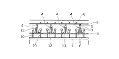
特許文献1には、橋梁上部工に用いられる鋼コンクリート合成床版の構造が開示されている。この鋼コンクリート合成床版は、図11に示すように、橋軸方向と平行な主桁上に敷設される型枠鋼板3上に、1本の上弦材5と2本の下弦材6,6間をラチス材7で連結してなるせん断補強用のトラス鉄筋4を、床版コンクリート中に配筋される上側主鉄筋8と平行に複数並列配置し、トラス鉄筋4と型枠鋼板3を溶接等で接合一体化し、トラス鉄筋4上に上側配力鉄筋9を直交するように配置し、さらに上側配力鉄筋9上に上側主鉄筋8を直交するように配置し、型枠鋼板3上にコンクリートを打設することで、型枠鋼板3を下側補強鋼材とする鋼コンクリート合成構造の床版を構成している。トラス鉄筋4は、コンクリート打設時において型枠鋼板3を補剛する機能と、床版完成時において床版コンクリートのせん断補強の機能とを有している。
この鋼コンクリート合成床版では、床版コンクリートの打設・硬化後、型枠鋼板3はコンクリートと一体化して鋼コンクリート合成床版としての主部材の機能を有するため、下側主鉄筋および下側配力筋が省略でき、製作の省力化が図られている。
In this steel-concrete composite floor slab, after placing and hardening the floor slab concrete, the
ところで、橋梁向けの鋼コンクリート合成構造では、床版と、床版を支持する主桁とをずれ止めで結合する必要があり、ずれ止めとしては頭付きスタッドやスラブアンカー等が用いられる。このずれ止めは、主桁上面に溶接で取り付けられ、床版コンクリート内に埋め込まれる。鋼コンクリート合成床版では、このような主桁との取り合い部において、主桁上面のずれ止めと型枠鋼板とが干渉しないように、主桁フランジ幅に合わせて型枠鋼板にスリットを設ける構造詳細を採用する必要がある。特許文献1では、この取り合い部については、考慮されていない。
By the way, in the steel-concrete composite structure for bridges, it is necessary to connect the floor slab and the main girder supporting the floor slab with a detent, and a headed stud, a slab anchor, or the like is used as the detent. This slip stopper is attached to the upper surface of the main girder by welding and embedded in the floor slab concrete. In the steel-concrete composite floor slab, a structure is provided with slits in the formwork steel plate in accordance with the width of the main girder flange so that the displacement of the top face of the main girder and the formwork steel plate do not interfere with each other at the joint with the main girder. Details need to be adopted. In
特許文献1の鋼コンクリート合成床版において、型枠鋼板にスリットを設けると、型枠材としての剛性や耐荷力が低下するので、これを補うためにトラス鉄筋を密に配置する必要が生じ、これにより材料費や加工費が増大するという問題がある。
In the steel-concrete composite floor slab of
また、道路橋床版においては、主桁近傍位置を輪荷重が通過する場合に床版の作用せん断力が大きくなることから、押抜きせん断耐力が小さな鉄筋コンクリート床版などでは、主桁に近い位置に押抜きせん断破壊が生じることが知られている。特許文献1の鋼コンクリート合成床版のトラス鉄筋は、床版のせん断補強機能も有していることから、主桁近傍の床版の押抜きせん断耐力を高めるためにトラス鉄筋を密に配置すると、この場合も材料費や加工費が増大するという問題がある。
In road bridge decks, the acting shear force of the floor slab increases when wheel load passes through the position near the main girder. It is known that punching shear failure occurs. Since the truss reinforcement of the steel concrete composite floor slab of
本発明は、前述のような問題の解決を図ったものであり、底鋼板上にせん断補強用のトラス鉄筋を並列配置して構成される鋼コンクリート合成床版において、単にトラス鉄筋の配置間隔を狭めた場合よりも効果的に、主桁上の底鋼板のスリット部を効果的に補強することができ、材料費や加工費の低減を図ることができる鋼コンクリート合成床版を提供するものである。 The present invention is intended to solve the above-described problems. In a steel-concrete composite slab constructed by arranging truss reinforcing bars for shear reinforcement on a bottom steel plate in parallel, the arrangement interval of truss reinforcing bars is simply set. It provides a steel-concrete composite floor slab that can effectively reinforce the slits of the bottom steel plate on the main girder and can reduce material costs and processing costs more effectively than when narrowed. is there.
本発明の請求項1に係る鋼コンクリート合成床版は、主桁上に敷設される底鋼板上にトラス鉄筋を主桁長手方向に間隔をおいて複数並列配置して底鋼板上面に接合一体化してなる床版パネルと、前記トラス鉄筋の上に配置される上側主鉄筋および上側配力鉄筋とを有し、前記底鋼板上にコンクリートを打設して構成される鋼コンクリート合成床版であって、主桁上面に接合される底鋼板の主桁位置部分には、主桁とコンクリートを一体化するためのスリット部が設けられ、このスリット部を挟んで両側に位置する底鋼板の上面には、スリット部を補強するための補強材が取り付けられていることを特徴とする。
In the steel-concrete composite slab according to
補強材は、基本的に底鋼板(型枠鋼板)のスリット部を跨いで連続する部材とし、主桁とほぼ直交する方向に配置する(図1〜図7参照)。後述するように、スリット部で連続させない場合もある(図9参照)。また、基本的に主桁に直交する橋軸直角方向すなわちトラス鉄筋と平行に配置されるが、トラス鉄筋に対して傾斜させて配置される場合もある(図10参照)。補強材の長さは、スリット部の幅に補強材と底鋼板との結合に必要な余長を加えた長さ以上、もしくは、床版が負の曲げモーメントを受ける範囲の長さ以上とし、床版パネルの全長にわたって配置することはせず、部分的に配置される。 The reinforcing material is basically a member that extends across the slit portion of the bottom steel plate (form steel plate) and is disposed in a direction substantially orthogonal to the main beam (see FIGS. 1 to 7). As will be described later, there are cases where the slit portions are not continuous (see FIG. 9). Moreover, although it is basically arranged in a direction perpendicular to the bridge axis perpendicular to the main girder, that is, parallel to the truss reinforcing bar, it may be inclined with respect to the truss reinforcing bar (see FIG. 10). The length of the reinforcing material is equal to or longer than the width of the slit portion plus the extra length necessary for the connection between the reinforcing material and the bottom steel plate, or the length of the range where the floor slab receives a negative bending moment, It is not arranged over the entire length of the floor slab panel, but is arranged partially.
本発明の請求項2に係る鋼コンクリート合成床版は、請求項1に記載の鋼コンクリート合成床版において、補強材は主桁長手方向に間隔をおいて複数並列配置されていることを特徴とする。
The steel-concrete composite floor slab according to
補強材は、主桁に直交する橋軸直角方向すなわちトラス鉄筋と平行に、あるいはトラス鉄筋に対して傾斜させて配置され、また各トラス鉄筋間(図1、図3参照)あるいはトラス鉄筋位置(図5、図6参照)に配置される。 The reinforcing member is arranged in a direction perpendicular to the bridge axis perpendicular to the main girder, that is, parallel to the truss reinforcing bar or inclined with respect to the truss reinforcing bar, and between the truss reinforcing bars (see FIGS. 1 and 3) or the truss reinforcing bar position ( (See FIGS. 5 and 6).
本発明の請求項3に係る鋼コンクリート合成床版は、請求項1または2に記載の鋼コンクリート合成床版において、補強材はスリット部を跨いで連続する部材であることを特徴とする。
The steel-concrete composite floor slab according to
床鋼パネルのトラス鉄筋は、通常、スリット部を跨いで連続するため、補強材もスリット部を跨いで連続させる。 Since the truss rebar of the floor steel panel is usually continuous across the slit portion, the reinforcing material is also continued across the slit portion.
本発明の請求項4に係る鋼コンクリート合成床版は、請求項1から3までのいずれか一つに記載の鋼コンクリート合成床版において、補強材による主桁中心位置を中心とする補強範囲は、床版支間長の1/3に、底鋼板と補強材との結合に必要な長さを加えた長さで、床版パネル長よりも短いことを特徴とする。
The steel-concrete composite floor slab according to
補強材がスリット部を跨いで連続する場合、連続しない場合のいずれの場合も、主桁の中心位置から左右にL/6(L:床版支間)ずつの範囲を超え、かつ、補強材と底鋼板との必要な長さ以上が確保されるようにし、床版が負の曲げモーメントを受ける範囲を補強する(図2参照)。床版が負の曲げモーメントを受ける範囲は、曲げモーメント勾配が大きく、床版の作用せん断力が大きい部位と一致するので、この補強材の補強範囲により、押抜きせん断破壊の危険がある部位の補強も兼ねることができる。 In both cases where the reinforcing material is continuous across the slit portion and not continuous, it exceeds the range of L / 6 (L: space between floor slabs) left and right from the center position of the main girder, and the reinforcing material More than the necessary length with the bottom steel plate is secured, and the range where the floor slab receives a negative bending moment is reinforced (see FIG. 2). The range in which the slab is subjected to negative bending moment is the same as the part where the bending moment gradient is large and the acting shear force of the slab is large. It can also serve as a reinforcement.
本発明の請求項5に係る鋼コンクリート合成床版は、請求項1から4までのいずれか一つに記載の鋼コンクリート合成床版において、補強材はトラス鉄筋であることを特徴とする。
The steel-concrete composite floor slab according to
補強トラス鉄筋の下弦材を溶接等で底鋼板の上面に固定する。補強材に床版パネルのトラス鉄筋と同じあるいは類似のトラス部材を用いることで、比較的低コストの補強材で効果的な補強を行うことができる。 The lower chord material of the reinforcing truss reinforcement is fixed to the upper surface of the bottom steel plate by welding or the like. By using a truss member that is the same as or similar to the truss reinforcing bar of the floor slab panel as the reinforcing material, effective reinforcement can be performed with a relatively low cost reinforcing material.
本発明の請求項6に係る鋼コンクリート合成床版は、請求項1から4までのいずれか一つに記載の鋼コンクリート合成床版において、補強材は鋼板リブであることを特徴とする。
The steel-concrete composite floor slab according to
鋼板リブは、縦にして底鋼板上に配置し、溶接等で固定する。この鋼板リブにより比較的低コストの補強材で効果的な補強を行うことができ、また設置スペースが比較的小さいため、主桁と床版の取り合い部におけるスタッド等のずれ止めの配置の自由度が増す(図4参照)。さらに、床版パネルのトラス鉄筋の内部に鋼板リブを配置することにより、さらに自由度が増す(図5参照)。 The steel plate rib is placed vertically on the bottom steel plate and fixed by welding or the like. This steel plate rib can be effectively reinforced with a relatively low cost reinforcing material, and since the installation space is relatively small, the degree of freedom of arrangement of stoppers such as studs at the joint between the main girder and the floor slab (See FIG. 4). Furthermore, the freedom degree increases further by arrange | positioning a steel plate rib inside the truss reinforcement of a floor slab panel (refer FIG. 5).
本発明の請求項7に係る鋼コンクリート合成床版は、請求項1から4までのいずれか一つに記載の鋼コンクリート合成床版において、補強材はトラス鉄筋の断面の一部または全部を取り囲むように打設されたコンクリートまたはモルタルであることを特徴とする。
The steel-concrete composite floor slab according to
床版パネルのトラス鉄筋の断面全体が埋設されるように打設し、あるいは例えば下部のみが埋設されるように打設し、コンクリートまたはモルタルを底鋼板に定着させる(図7、図8参照)。この先付けコンクリートまたはモルタルは、完成時には床版コンクリートと一体化し、また鋼材を用いるより経済的であり、比較的低コストの補強材で効果的な補強を行うことができる。 The floor slab panel is placed so that the entire cross section of the truss rebar is buried, or, for example, only the lower part is buried, and concrete or mortar is fixed to the bottom steel plate (see FIGS. 7 and 8). . This pre-concrete concrete or mortar is integrated with the floor slab concrete when completed, is more economical than using steel, and can be effectively reinforced with a relatively low cost reinforcement.
以上のような本発明では、床版パネルの底鋼板が欠損していて型枠としての弱点となるスリット部に補強材を追加することで、必要な箇所だけを比較的簡易な部材により効果的に補強することができる。また、完成後の床版は主桁近傍の作用せん断力が大きい部位のせん断耐力が高まる。結果として、同じ長さのトラス鉄筋を密に並列配置する場合よりも、トラス鉄筋の使用量を減らすことができ、床版全体での材料費や加工費を低減することができる。 In the present invention as described above, by adding a reinforcing material to the slit portion which is a weak point as a formwork when the bottom steel plate of the floor slab panel is missing, only a necessary portion can be effectively obtained by a relatively simple member. Can be reinforced. In addition, the finished slab has a higher shear strength in the region where the acting shear force is greater near the main girder. As a result, it is possible to reduce the amount of truss reinforcing bars used compared to the case where truss reinforcing bars having the same length are closely arranged in parallel, and to reduce material costs and processing costs of the entire floor slab.
(1)底鋼板上にせん断補強用のトラス鉄筋を並列配置して構成される鋼コンクリート合成床版において、主桁と床版との取り合い部における底鋼板のスリット部を挟んで両側に位置する底鋼板の上面に、トラス鉄筋、鋼板リブ、コンクリートリブ等の補強材を取り付けるようにしているため、単にトラス鉄筋の配置間隔を狭めた場合よりも効果的に、主桁上の底鋼板のスリット部を効果的に補強することができ、材料費や加工費の低減を図ることができる。 (1) In a steel-concrete composite floor slab constructed by arranging truss reinforcing bars for shear reinforcement on the bottom steel plate in parallel, located on both sides of the bottom steel plate slit at the joint between the main girder and the floor slab Since reinforcing materials such as truss rebars, steel plate ribs and concrete ribs are attached to the top surface of the bottom steel plate, the slits of the bottom steel plate on the main girder are more effective than simply narrowing the space between truss rebars. The portion can be effectively reinforced, and the material cost and processing cost can be reduced.
(2)コンクリート打設時には比較的簡易な補強材により型枠材としての床版パネルの剛性や耐荷力が向上し、また完成後の床版は主桁近傍の作用せん断力が大きい部位のせん断耐力が向上するため、低コストで耐久性の高い鋼コンクリート合成床版が得られる。 (2) When placing concrete, the rigidity and load bearing capacity of the floor slab panel as a formwork material are improved by a relatively simple reinforcing material, and the finished floor slab is sheared at a portion where the acting shear force near the main girder is large. Since the yield strength is improved, a steel-concrete composite slab with low cost and high durability can be obtained.
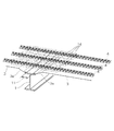
以下、本発明を図示する実施形態に基づいて説明する。この実施形態は橋梁の上部工に適用した例である。図1、図2は、本発明の鋼コンクリート合成床版の第1実施形態(補強材がトラス鉄筋)を示す斜視図、断面図である。図3、図4、図5は、本発明の鋼コンクリート合成床版の第2実施形態(補強材が鋼板リブ)を示す斜視図、断面図である。図6、図7、図8は、本発明の鋼コンクリート合成床版の第3実施形態(補強材がコンクリート)を示す斜視図、断面図である。図9は、本発明の鋼コンクリート合成床版の第4実施形態(橋梁の幅員が大きい場合)を示す断面図である。図10は、本発明の鋼コンクリート合成床版の第5実施形態(斜角を有する橋梁の場合)を示す平面図、断面図、拡大平面図である。 Hereinafter, the present invention will be described based on the illustrated embodiments. This embodiment is an example applied to a bridge superstructure. 1 and 2 are a perspective view and a sectional view showing a first embodiment of a steel concrete composite slab of the present invention (reinforcing material is a truss reinforcing bar). 3, 4, and 5 are a perspective view and a cross-sectional view showing a second embodiment of the steel concrete composite slab of the present invention (the reinforcing material is a steel plate rib). FIGS. 6, 7, and 8 are a perspective view and a cross-sectional view showing a third embodiment (a reinforcing material is concrete) of the steel-concrete composite floor slab of the present invention. FIG. 9 is a cross-sectional view showing a fourth embodiment of the steel-concrete composite floor slab of the present invention (when the bridge width is large). FIG. 10 is a plan view, a sectional view, and an enlarged plan view showing a fifth embodiment (in the case of a bridge having a bevel) of a steel concrete composite slab of the present invention.
図1、図2に示すように、橋梁上部工の主桁1が橋軸方向と平行に橋軸直角方向に床版支間長Lをおいて配置されており、この主桁1上に底鋼板(型枠鋼板)3とトラス鉄筋4からなる床版パネル(型枠材)2が設置される。トラス鉄筋4は橋軸直角方向と平行に橋軸方向に間隔をおいて複数並列配置され、底鋼板3の上面に溶接等で接合一体化される。このトラス鉄筋4の上に上側配力鉄筋9をトラス鉄筋4と直交するように配置し、さらに上側配力鉄筋9の上に上側主鉄筋8を上側配力鉄筋9と直交するように配置し(図4、5参照)、底鋼板3上にコンクリートを打設することにより鋼コンクリート合成床版が形成される。
As shown in FIGS. 1 and 2, a
主桁1と底鋼板3との取り合い部は、主桁上面にスタッド10(図4、5参照)等のずれ止めを設けるため、主桁フランジ幅より小さい幅のスリット部11が設けられている。また、主桁1に取り付けられる底鋼板3の端部には下方に向かって傾斜するハンチ3aが形成されており、このハンチ3aの先端を主桁1の上面に添接してボルト等で固定することによりスリット部11が形成される。
The joint portion between the
トラス鉄筋4は、例えば、上弦材5と下弦材6を有し、上弦材5と下弦材6とを波状に折り曲げたラチス材7で連結して立体トラス状に組み立てたものである。各下弦材6が底鋼板3の上面に溶接等で固定される。この図1、図2の実施形態では、トラス鉄筋4は、スリット部11を跨いで連続しており、この底鋼板3とトラス鉄筋4からなる床版パネル2が工場で製作され、あるいは現場で組み立てられる。
The
このような構造の鋼コンクリート合成床版において、底鋼板3にスリット部11が設けられていると、剛性や耐荷力が低下するため、図1、図2に示すように、補強材としてスリット部11を跨いで連続する所定長さのトラス鉄筋12を用い、これを各トラス鉄筋4の間にトラス鉄筋4と平行に配置し、スリット部を挟んで両側の底鋼板3の上面に固定し、スリット部11を補強する。この補強トラス鉄筋12は、トラス鉄筋4と同様の立体トラス形状を用いるのが好ましいが、その他の形状でもよい。
In the steel-concrete composite floor slab having such a structure, if the
補強トラス鉄筋12による補強範囲は、スリット部11を跨ぎ、底鋼板3との結合に必要な定着長が確保されるように設定される。具体的には、主桁1の中心位置から左右にL/6(L:床版支間)ずつの範囲を超え、かつ、補強トラス鉄筋12と底鋼板3との固定に必要な長さ以上が確保されるようにし、床版が負の曲げモーメントを受ける範囲を補強する。床版が負の曲げモーメントを受ける範囲は、曲げモーメント勾配が大きく、床版の作用せん断力が大きい部位と一致するので、このような補強トラス鉄筋12の配置により、押抜きせん断破壊の危険がある部位の補強も兼ねることができる。
The range of reinforcement by the reinforcing
図3〜図5の実施形態は、補強材として鋼板リブ13を用いた例である。この補強鋼板リブ13は、縦にして用い、スリット部11を跨いで配置し、下部を底鋼板3の上面に溶接等で固定する。補強範囲は補強トラス鉄筋12の場合と同じである。
The embodiment of FIGS. 3 to 5 is an example in which the
図3、図4の例では、上側配力鉄筋9の下に配置できる高さの補強鋼板リブ13を各トラス鉄筋4の間にトラス鉄筋4と平行に配置している。
In the example of FIGS. 3 and 4, reinforcing
図5の例では、補強鋼板リブ13をトラス鉄筋4の内部に配置している。補強鋼板リブ13を左右のラチス材7の間に配置することにより、スタッド10の配置の自由度が増す。合成桁では、主桁と床版とを一体化させて荷重に抵抗させるため、主桁上面のスタッド本数が多くなり、主桁と床版の取り合い部において部材配置の問題が生じやすい。図5の例は、このような取り合い部における部材配置の点で好ましい。
In the example of FIG. 5, the reinforcing
図6〜図8の実施形態は、補強材としてコンクリートやモルタル14を用いた例である。トラス鉄筋4の断面の一部または全部を取り囲むように先打ちコンクリートやモルタル14を打設する。図7はトラス鉄筋4を完全に埋設する場合、図8はトラス鉄筋4の下部のみを埋設する場合である。この場合も、先打ちコンクリートやモルタル14をスリット部11を跨いで打設し、底鋼板3の上面に定着させる。補強範囲は、補強トラス鉄筋12の場合と同様である。
The embodiment of FIGS. 6 to 8 is an example in which concrete or
この先打ちコンクリート・モルタル14による補強材は、工場施工とすることもできる。工場施工の補強材は、トラス鉄筋4を取り囲むように打設することで、補強材が運搬中に割れたり剥落したりすることを防止できる。完成時には、コンクリートやモルタル14は床版コンクリートと一体化する。コンクリートやモルタルを用いるため、鋼材を用いる場合よりも経済的である。
The reinforcing material by the precast
図9の実施形態は、主桁上で床版パネルを連続させない例である。補強材は原則として主桁上の底鋼板のスリット部を跨ぐように配置するが、図9に示すように、底鋼板3のスリット部11の上で連続させない場合もある。図9には、橋梁の幅員が大きい場合の例を示している。橋梁の幅員が大きくなり、床版パネル2が長くなると、輸送上の制約から床版パネルには橋軸方向の継手20を設ける必要がある。このような場合、中央の主桁上で床版パネルはピン支持(曲げモーメントの拘束がない)されるため、コンクリート打設時の荷重によって、中央主桁上の床版パネルに負の曲げモーメントが生じることはなく、補強トラス鉄筋12等の補強材を連続させなくても必要な構造性能を満足させることができる。
The embodiment of FIG. 9 is an example in which the floor slab panels are not continued on the main beam. In principle, the reinforcing material is disposed so as to straddle the slit portion of the bottom steel plate on the main girder, but may not be continued on the
図10の実施形態は、斜角を有する橋梁に適用した例である。補強材はトラス鉄筋と概ね平行に配置するが、補強材とトラス鉄筋との間に角度を設ける場合がある。図10には、斜角を有する橋梁の場合の床版パネル2の配置方法を示している。斜角を有する橋梁では、橋梁端部のパネルを長方形ではなく異形パネルとすることがあり、この場合、補強トラス鉄筋12等の補強材とトラス鉄筋4との間に角度を設けてパネル形状に適応させる。
The embodiment of FIG. 10 is an example applied to a bridge having an oblique angle. Although the reinforcing material is arranged substantially parallel to the truss reinforcing bar, an angle may be provided between the reinforcing material and the truss reinforcing bar. FIG. 10 shows an arrangement method of the
なお、以上は橋梁上部工に適用した場合を示したが、その他の床版にも本発明の鋼コンクリート合成床版にも適用することができる。 In addition, although the above showed the case where it applied to a bridge superstructure, it can apply also to other floor slabs and the steel concrete composite slab of this invention.
1…主桁
2…床版パネル(型枠材)
3…底鋼板(型枠鋼板)
3a…ハンチ
4…トラス鉄筋
5…上弦材
6…下弦材
7…ラチス材
8…上側主鉄筋
9…上側配力鉄筋
10…スタッド
11…スリット部
12…補強トラス鉄筋(補強材)
13…補強鋼板リブ(補強材)
14…先打ちコンクリートやモルタル(補強材)
20…橋軸方向の継手
1 ...
3 ... bottom steel plate (formwork steel plate)
3a ...
13 ... Reinforced steel plate rib (reinforcing material)
14 ... Precast concrete and mortar (reinforcing material)
20 ... Bridge axis joint
Claims (7)
主桁上面に接合される底鋼板の主桁位置部分には、主桁とコンクリートを一体化するためのスリット部が設けられ、このスリット部を挟んで両側に位置する底鋼板の上面には、スリット部を補強するための補強材が取り付けられていることを特徴とする鋼コンクリート合成床版。 A floor slab panel in which a plurality of truss rebars are arranged in parallel on the bottom steel plate laid on the main girder and spaced in the longitudinal direction of the main girder, and are integrally joined to the top surface of the bottom steel plate, and is disposed on the truss rebar. A steel-concrete composite slab comprising an upper main reinforcing bar and an upper distribution reinforcing bar, and configured by placing concrete on the bottom steel plate,
The main girder position portion of the bottom steel plate joined to the top surface of the main girder is provided with a slit portion for integrating the main girder and concrete, and on the top surface of the bottom steel plate located on both sides across the slit portion, A steel-concrete composite floor slab, to which a reinforcing material for reinforcing the slit portion is attached.
Priority Applications (1)
| Application Number | Priority Date | Filing Date | Title |
|---|---|---|---|
| JP2006267076A JP2008088634A (en) | 2006-09-29 | 2006-09-29 | Composite steel-concrete floor slab |
Applications Claiming Priority (1)
| Application Number | Priority Date | Filing Date | Title |
|---|---|---|---|
| JP2006267076A JP2008088634A (en) | 2006-09-29 | 2006-09-29 | Composite steel-concrete floor slab |
Publications (1)
| Publication Number | Publication Date |
|---|---|
| JP2008088634A true JP2008088634A (en) | 2008-04-17 |
Family
ID=39373070
Family Applications (1)
| Application Number | Title | Priority Date | Filing Date |
|---|---|---|---|
| JP2006267076A Pending JP2008088634A (en) | 2006-09-29 | 2006-09-29 | Composite steel-concrete floor slab |
Country Status (1)
| Country | Link |
|---|---|
| JP (1) | JP2008088634A (en) |
Cited By (5)
| Publication number | Priority date | Publication date | Assignee | Title |
|---|---|---|---|---|
| KR101004617B1 (en) | 2010-08-12 | 2011-01-03 | 이엔이건설주식회사 | Steel slab pannel and composited bridge construction method using temporary steel reinforcing rib and concrete reinforcing rib |
| KR101004618B1 (en) | 2010-08-12 | 2011-01-03 | 이엔이건설주식회사 | Composite girder bridge construction method using temporary steel lateral rib and permanent concrete lateral rib |
| JP2011099201A (en) * | 2009-11-04 | 2011-05-19 | Tobishima Corp | Aseismic reinforcement structure for existing reinforced concrete bridge pier |
| KR101059902B1 (en) * | 2008-06-05 | 2011-08-29 | (주)영구조엔지니어링 | Truss Deck Installation Structure |
| CN103334377A (en) * | 2013-07-03 | 2013-10-02 | 中铁大桥勘测设计院集团有限公司 | A kind of novel structure of beam bridge floor in length and breadth |
Citations (9)
| Publication number | Priority date | Publication date | Assignee | Title |
|---|---|---|---|---|
| JPS63176506A (en) * | 1987-01-12 | 1988-07-20 | 川崎重工業株式会社 | Execution of synthetic floor panel bridge composed of steel and concrete |
| JPH083928A (en) * | 1994-06-17 | 1996-01-09 | Ishikawajima Constr Materials Co Ltd | Connection material structure of precast floor slab |
| JPH08253909A (en) * | 1995-03-17 | 1996-10-01 | Sumitomo Metal Ind Ltd | Ferroconcrete floor slab for bridge and form therefor |
| JPH10227011A (en) * | 1997-02-17 | 1998-08-25 | Matsuo Kyoryo Kk | Steel form with main reinforcement for bridge floor, and construction of bridge floor using the form |
| JPH10227010A (en) * | 1997-02-17 | 1998-08-25 | Matsuo Kyoryo Kk | Steel form with main reinforcement for bridge floor panel and bridge floor panel construction method using it |
| JP2001279853A (en) * | 2000-03-31 | 2001-10-10 | Hitachi Zosen Corp | Synthetic floor slab and half precast floor slab |
| JP2002180420A (en) * | 2000-10-05 | 2002-06-26 | Mitsubishi Heavy Ind Ltd | Steel-concrete synthetic floor slab and its execution method and constitutive member of this synthetic floor slab and bridge suing this synthetic floor slab |
| JP2002302909A (en) * | 2001-04-10 | 2002-10-18 | Yokogawa Koji Kk | Floor slab installation method in continuous beam bridge |
| JP2004232229A (en) * | 2003-01-28 | 2004-08-19 | Nippon Kaiser Kk | Precast concrete slab |
-
2006
- 2006-09-29 JP JP2006267076A patent/JP2008088634A/en active Pending
Patent Citations (9)
| Publication number | Priority date | Publication date | Assignee | Title |
|---|---|---|---|---|
| JPS63176506A (en) * | 1987-01-12 | 1988-07-20 | 川崎重工業株式会社 | Execution of synthetic floor panel bridge composed of steel and concrete |
| JPH083928A (en) * | 1994-06-17 | 1996-01-09 | Ishikawajima Constr Materials Co Ltd | Connection material structure of precast floor slab |
| JPH08253909A (en) * | 1995-03-17 | 1996-10-01 | Sumitomo Metal Ind Ltd | Ferroconcrete floor slab for bridge and form therefor |
| JPH10227011A (en) * | 1997-02-17 | 1998-08-25 | Matsuo Kyoryo Kk | Steel form with main reinforcement for bridge floor, and construction of bridge floor using the form |
| JPH10227010A (en) * | 1997-02-17 | 1998-08-25 | Matsuo Kyoryo Kk | Steel form with main reinforcement for bridge floor panel and bridge floor panel construction method using it |
| JP2001279853A (en) * | 2000-03-31 | 2001-10-10 | Hitachi Zosen Corp | Synthetic floor slab and half precast floor slab |
| JP2002180420A (en) * | 2000-10-05 | 2002-06-26 | Mitsubishi Heavy Ind Ltd | Steel-concrete synthetic floor slab and its execution method and constitutive member of this synthetic floor slab and bridge suing this synthetic floor slab |
| JP2002302909A (en) * | 2001-04-10 | 2002-10-18 | Yokogawa Koji Kk | Floor slab installation method in continuous beam bridge |
| JP2004232229A (en) * | 2003-01-28 | 2004-08-19 | Nippon Kaiser Kk | Precast concrete slab |
Cited By (6)
| Publication number | Priority date | Publication date | Assignee | Title |
|---|---|---|---|---|
| KR101059902B1 (en) * | 2008-06-05 | 2011-08-29 | (주)영구조엔지니어링 | Truss Deck Installation Structure |
| JP2011099201A (en) * | 2009-11-04 | 2011-05-19 | Tobishima Corp | Aseismic reinforcement structure for existing reinforced concrete bridge pier |
| KR101004617B1 (en) | 2010-08-12 | 2011-01-03 | 이엔이건설주식회사 | Steel slab pannel and composited bridge construction method using temporary steel reinforcing rib and concrete reinforcing rib |
| KR101004618B1 (en) | 2010-08-12 | 2011-01-03 | 이엔이건설주식회사 | Composite girder bridge construction method using temporary steel lateral rib and permanent concrete lateral rib |
| CN103334377A (en) * | 2013-07-03 | 2013-10-02 | 中铁大桥勘测设计院集团有限公司 | A kind of novel structure of beam bridge floor in length and breadth |
| CN103334377B (en) * | 2013-07-03 | 2015-09-02 | 中铁大桥勘测设计院集团有限公司 | A kind of Novel longitudinal-transvebeam beam bridge floor structure |
Similar Documents
| Publication | Publication Date | Title |
|---|---|---|
| KR101168763B1 (en) | Composite bridge construction method | |
| JP6375079B1 (en) | Joint structure of precast composite floor slab perpendicular to the bridge axis and its construction method | |
| JP2008088634A (en) | Composite steel-concrete floor slab | |
| JP4416337B2 (en) | Construction method of the replacement composite floor slab girder bridge | |
| CN110392758B (en) | Inverted T-shaped section mixed prestressed concrete beam and panel construction method using same | |
| JP2003119718A (en) | Bridge | |
| JP2006009449A (en) | Truss panel girder and precast truss panel | |
| KR101760429B1 (en) | Negative moment part steel box girder and bridge construction method using the same | |
| JP5833616B2 (en) | Construction method of joint structure of concrete precast slab for bridge | |
| JP3830767B2 (en) | Continuous girder for bridge | |
| JP4644146B2 (en) | PC box girder bridge | |
| JPH04228710A (en) | Road slab for bridge | |
| KR101752285B1 (en) | Hybrid beam with wide PSC lower flange and enlarged section upper flange and structure frame using the same | |
| JP2508677B2 (en) | Reinforcement method of bridge reinforced concrete slab | |
| JP2011157733A (en) | Method of constructing composite steel floor slab bridge, steel floor slab with rib, and composite steel floor slab bridge | |
| JP4005774B2 (en) | Bridge girder | |
| JP2008231688A (en) | Bridge structure using composite floor slab, its construction method, and form for composite floor slab | |
| JP4293696B2 (en) | Construction method of composite floor slab bridge | |
| JPH11293626A (en) | Bridge structure | |
| JP2002275833A (en) | Continuing method of simple beam of existing bridge and continuous beam structure | |
| KR101329482B1 (en) | Deflection control structure of deck plate of slim floor with stiffness reinforcing link bar and construction method thereof | |
| KR20080004752U (en) | Composite bridge | |
| JP2000008325A (en) | Combined girder structure for floor slab | |
| JP4411654B2 (en) | Synthetic floor slab with reinforcement | |
| JP3950748B2 (en) | Bridge girder |
Legal Events
| Date | Code | Title | Description |
|---|---|---|---|
| A621 | Written request for application examination |
Free format text: JAPANESE INTERMEDIATE CODE: A621 Effective date: 20090325 |
|
| A711 | Notification of change in applicant |
Free format text: JAPANESE INTERMEDIATE CODE: A712 Effective date: 20090715 |
|
| A977 | Report on retrieval |
Effective date: 20100915 Free format text: JAPANESE INTERMEDIATE CODE: A971007 |
|
| A131 | Notification of reasons for refusal |
Effective date: 20100928 Free format text: JAPANESE INTERMEDIATE CODE: A131 |
|
| A521 | Written amendment |
Effective date: 20101129 Free format text: JAPANESE INTERMEDIATE CODE: A523 |
|
| A131 | Notification of reasons for refusal |
Free format text: JAPANESE INTERMEDIATE CODE: A131 Effective date: 20101221 |
|
| A521 | Written amendment |
Free format text: JAPANESE INTERMEDIATE CODE: A523 Effective date: 20110221 |
|
| A02 | Decision of refusal |
Effective date: 20110322 Free format text: JAPANESE INTERMEDIATE CODE: A02 |