WO2023182247A1 - SiO2Al2O3含有ゾル溶液の合成方法、及び、多孔質アルミナ膜の形成方法 - Google Patents
SiO2Al2O3含有ゾル溶液の合成方法、及び、多孔質アルミナ膜の形成方法 Download PDFInfo
- Publication number
- WO2023182247A1 WO2023182247A1 PCT/JP2023/010790 JP2023010790W WO2023182247A1 WO 2023182247 A1 WO2023182247 A1 WO 2023182247A1 JP 2023010790 W JP2023010790 W JP 2023010790W WO 2023182247 A1 WO2023182247 A1 WO 2023182247A1
- Authority
- WO
- WIPO (PCT)
- Prior art keywords
- sio
- solution
- sol
- sol solution
- sample
- Prior art date
- Legal status (The legal status is an assumption and is not a legal conclusion. Google has not performed a legal analysis and makes no representation as to the accuracy of the status listed.)
- Ceased
Links
Images












Classifications
-
- C—CHEMISTRY; METALLURGY
- C01—INORGANIC CHEMISTRY
- C01F—COMPOUNDS OF THE METALS BERYLLIUM, MAGNESIUM, ALUMINIUM, CALCIUM, STRONTIUM, BARIUM, RADIUM, THORIUM, OR OF THE RARE-EARTH METALS
- C01F7/00—Compounds of aluminium
- C01F7/02—Aluminium oxide; Aluminium hydroxide; Aluminates
- C01F7/34—Preparation of aluminium hydroxide by precipitation from solutions containing aluminium salts
-
- B—PERFORMING OPERATIONS; TRANSPORTING
- B01—PHYSICAL OR CHEMICAL PROCESSES OR APPARATUS IN GENERAL
- B01J—CHEMICAL OR PHYSICAL PROCESSES, e.g. CATALYSIS OR COLLOID CHEMISTRY; THEIR RELEVANT APPARATUS
- B01J21/00—Catalysts comprising the elements, oxides, or hydroxides of magnesium, boron, aluminium, carbon, silicon, titanium, zirconium, or hafnium
- B01J21/12—Silica and alumina
-
- B—PERFORMING OPERATIONS; TRANSPORTING
- B01—PHYSICAL OR CHEMICAL PROCESSES OR APPARATUS IN GENERAL
- B01J—CHEMICAL OR PHYSICAL PROCESSES, e.g. CATALYSIS OR COLLOID CHEMISTRY; THEIR RELEVANT APPARATUS
- B01J21/00—Catalysts comprising the elements, oxides, or hydroxides of magnesium, boron, aluminium, carbon, silicon, titanium, zirconium, or hafnium
-
- B—PERFORMING OPERATIONS; TRANSPORTING
- B01—PHYSICAL OR CHEMICAL PROCESSES OR APPARATUS IN GENERAL
- B01J—CHEMICAL OR PHYSICAL PROCESSES, e.g. CATALYSIS OR COLLOID CHEMISTRY; THEIR RELEVANT APPARATUS
- B01J23/00—Catalysts comprising metals or metal oxides or hydroxides, not provided for in group B01J21/00
- B01J23/02—Catalysts comprising metals or metal oxides or hydroxides, not provided for in group B01J21/00 of the alkali- or alkaline earth metals or beryllium
-
- B—PERFORMING OPERATIONS; TRANSPORTING
- B01—PHYSICAL OR CHEMICAL PROCESSES OR APPARATUS IN GENERAL
- B01J—CHEMICAL OR PHYSICAL PROCESSES, e.g. CATALYSIS OR COLLOID CHEMISTRY; THEIR RELEVANT APPARATUS
- B01J37/00—Processes, in general, for preparing catalysts; Processes, in general, for activation of catalysts
- B01J37/009—Preparation by separation, e.g. by filtration, decantation, screening
-
- B—PERFORMING OPERATIONS; TRANSPORTING
- B01—PHYSICAL OR CHEMICAL PROCESSES OR APPARATUS IN GENERAL
- B01J—CHEMICAL OR PHYSICAL PROCESSES, e.g. CATALYSIS OR COLLOID CHEMISTRY; THEIR RELEVANT APPARATUS
- B01J37/00—Processes, in general, for preparing catalysts; Processes, in general, for activation of catalysts
- B01J37/02—Impregnation, coating or precipitation
- B01J37/0215—Coating
-
- B—PERFORMING OPERATIONS; TRANSPORTING
- B01—PHYSICAL OR CHEMICAL PROCESSES OR APPARATUS IN GENERAL
- B01J—CHEMICAL OR PHYSICAL PROCESSES, e.g. CATALYSIS OR COLLOID CHEMISTRY; THEIR RELEVANT APPARATUS
- B01J37/00—Processes, in general, for preparing catalysts; Processes, in general, for activation of catalysts
- B01J37/02—Impregnation, coating or precipitation
- B01J37/0236—Drying, e.g. preparing a suspension, adding a soluble salt and drying
-
- B—PERFORMING OPERATIONS; TRANSPORTING
- B01—PHYSICAL OR CHEMICAL PROCESSES OR APPARATUS IN GENERAL
- B01J—CHEMICAL OR PHYSICAL PROCESSES, e.g. CATALYSIS OR COLLOID CHEMISTRY; THEIR RELEVANT APPARATUS
- B01J37/00—Processes, in general, for preparing catalysts; Processes, in general, for activation of catalysts
- B01J37/02—Impregnation, coating or precipitation
- B01J37/03—Precipitation; Co-precipitation
- B01J37/031—Precipitation
-
- B—PERFORMING OPERATIONS; TRANSPORTING
- B01—PHYSICAL OR CHEMICAL PROCESSES OR APPARATUS IN GENERAL
- B01J—CHEMICAL OR PHYSICAL PROCESSES, e.g. CATALYSIS OR COLLOID CHEMISTRY; THEIR RELEVANT APPARATUS
- B01J37/00—Processes, in general, for preparing catalysts; Processes, in general, for activation of catalysts
- B01J37/06—Washing
-
- B—PERFORMING OPERATIONS; TRANSPORTING
- B01—PHYSICAL OR CHEMICAL PROCESSES OR APPARATUS IN GENERAL
- B01J—CHEMICAL OR PHYSICAL PROCESSES, e.g. CATALYSIS OR COLLOID CHEMISTRY; THEIR RELEVANT APPARATUS
- B01J37/00—Processes, in general, for preparing catalysts; Processes, in general, for activation of catalysts
- B01J37/08—Heat treatment
-
- C—CHEMISTRY; METALLURGY
- C01—INORGANIC CHEMISTRY
- C01B—NON-METALLIC ELEMENTS; COMPOUNDS THEREOF; METALLOIDS OR COMPOUNDS THEREOF NOT COVERED BY SUBCLASS C01C
- C01B33/00—Silicon; Compounds thereof
- C01B33/113—Silicon oxides; Hydrates thereof
- C01B33/12—Silica; Hydrates thereof, e.g. lepidoic silicic acid
- C01B33/14—Colloidal silica, e.g. dispersions, gels, sols
- C01B33/141—Preparation of hydrosols or aqueous dispersions
-
- C—CHEMISTRY; METALLURGY
- C01—INORGANIC CHEMISTRY
- C01F—COMPOUNDS OF THE METALS BERYLLIUM, MAGNESIUM, ALUMINIUM, CALCIUM, STRONTIUM, BARIUM, RADIUM, THORIUM, OR OF THE RARE-EARTH METALS
- C01F7/00—Compounds of aluminium
- C01F7/02—Aluminium oxide; Aluminium hydroxide; Aluminates
- C01F7/44—Dehydration of aluminium oxide or hydroxide, i.e. all conversions of one form into another involving a loss of water
-
- C—CHEMISTRY; METALLURGY
- C04—CEMENTS; CONCRETE; ARTIFICIAL STONE; CERAMICS; REFRACTORIES
- C04B—LIME, MAGNESIA; SLAG; CEMENTS; COMPOSITIONS THEREOF, e.g. MORTARS, CONCRETE OR LIKE BUILDING MATERIALS; ARTIFICIAL STONE; CERAMICS; REFRACTORIES; TREATMENT OF NATURAL STONE
- C04B41/00—After-treatment of mortars, concrete, artificial stone or ceramics; Treatment of natural stone
- C04B41/009—After-treatment of mortars, concrete, artificial stone or ceramics; Treatment of natural stone characterised by the material treated
-
- C—CHEMISTRY; METALLURGY
- C04—CEMENTS; CONCRETE; ARTIFICIAL STONE; CERAMICS; REFRACTORIES
- C04B—LIME, MAGNESIA; SLAG; CEMENTS; COMPOSITIONS THEREOF, e.g. MORTARS, CONCRETE OR LIKE BUILDING MATERIALS; ARTIFICIAL STONE; CERAMICS; REFRACTORIES; TREATMENT OF NATURAL STONE
- C04B41/00—After-treatment of mortars, concrete, artificial stone or ceramics; Treatment of natural stone
- C04B41/45—Coating or impregnating, e.g. injection in masonry, partial coating of green or fired ceramics, organic coating compositions for adhering together two concrete elements
- C04B41/50—Coating or impregnating, e.g. injection in masonry, partial coating of green or fired ceramics, organic coating compositions for adhering together two concrete elements with inorganic materials
- C04B41/5025—Coating or impregnating, e.g. injection in masonry, partial coating of green or fired ceramics, organic coating compositions for adhering together two concrete elements with inorganic materials with ceramic materials
- C04B41/5031—Alumina
-
- C—CHEMISTRY; METALLURGY
- C04—CEMENTS; CONCRETE; ARTIFICIAL STONE; CERAMICS; REFRACTORIES
- C04B—LIME, MAGNESIA; SLAG; CEMENTS; COMPOSITIONS THEREOF, e.g. MORTARS, CONCRETE OR LIKE BUILDING MATERIALS; ARTIFICIAL STONE; CERAMICS; REFRACTORIES; TREATMENT OF NATURAL STONE
- C04B41/00—After-treatment of mortars, concrete, artificial stone or ceramics; Treatment of natural stone
- C04B41/80—After-treatment of mortars, concrete, artificial stone or ceramics; Treatment of natural stone of only ceramics
- C04B41/81—Coating or impregnation
- C04B41/85—Coating or impregnation with inorganic materials
- C04B41/87—Ceramics
-
- B—PERFORMING OPERATIONS; TRANSPORTING
- B01—PHYSICAL OR CHEMICAL PROCESSES OR APPARATUS IN GENERAL
- B01J—CHEMICAL OR PHYSICAL PROCESSES, e.g. CATALYSIS OR COLLOID CHEMISTRY; THEIR RELEVANT APPARATUS
- B01J2235/00—Indexing scheme associated with group B01J35/00, related to the analysis techniques used to determine the catalysts form or properties
- B01J2235/30—Scanning electron microscopy; Transmission electron microscopy
-
- C—CHEMISTRY; METALLURGY
- C04—CEMENTS; CONCRETE; ARTIFICIAL STONE; CERAMICS; REFRACTORIES
- C04B—LIME, MAGNESIA; SLAG; CEMENTS; COMPOSITIONS THEREOF, e.g. MORTARS, CONCRETE OR LIKE BUILDING MATERIALS; ARTIFICIAL STONE; CERAMICS; REFRACTORIES; TREATMENT OF NATURAL STONE
- C04B2111/00—Mortars, concrete or artificial stone or mixtures to prepare them, characterised by specific function, property or use
- C04B2111/00474—Uses not provided for elsewhere in C04B2111/00
- C04B2111/00793—Uses not provided for elsewhere in C04B2111/00 as filters or diaphragms
-
- C—CHEMISTRY; METALLURGY
- C04—CEMENTS; CONCRETE; ARTIFICIAL STONE; CERAMICS; REFRACTORIES
- C04B—LIME, MAGNESIA; SLAG; CEMENTS; COMPOSITIONS THEREOF, e.g. MORTARS, CONCRETE OR LIKE BUILDING MATERIALS; ARTIFICIAL STONE; CERAMICS; REFRACTORIES; TREATMENT OF NATURAL STONE
- C04B2111/00—Mortars, concrete or artificial stone or mixtures to prepare them, characterised by specific function, property or use
- C04B2111/00474—Uses not provided for elsewhere in C04B2111/00
- C04B2111/0081—Uses not provided for elsewhere in C04B2111/00 as catalysts or catalyst carriers
Definitions
- the present invention relates to a method for synthesizing a sol solution containing SiO 2 Al 2 O 3 for forming porous alumina doped with silica, and a method for forming a heat-resistant porous alumina film.
- Porous alumina materials having a large specific surface area are useful as catalyst carriers for supporting catalyst substances, filters, etc., and studies have been made to improve their properties (for example, Patent Documents 1 and 2). (See 5th grade).
- the catalyst carrier needs to suppress a decrease in specific surface area, a change in composition due to hydration reaction, etc. under severe conditions such as high temperature, high pressure, and the presence of water vapor.
- the inventors of the present application have discovered that Al 2 O 3 to which SiO 2 or Ba is added maintains a high specific surface area even after firing at 1200°C for several tens of hours, and ⁇ -Al 2 O due to the transformation of Al 2 O 3 It has been clarified that the formation of No. 3 is not observed (see Patent Document 6 above).
- Such highly heat-resistant alumina powder can be formed into pellets or the like and applied as a catalyst carrier for reactions that require high heat resistance, such as steam reforming reactions.
- the catalyst carrier formed into pellets has an increased pressure loss under high SV conditions.
- An example of how the reaction progresses efficiently on the catalyst surface layer under high SV conditions is to wash-coat a cordierite honeycomb with a carrier component such as alumina to form an alumina layer that supports noble metals.
- Automobile exhaust gas purification catalysts and the like are known.
- the alumina layer obtained using existing technology has insufficient heat resistance, sintering tends to proceed under high temperature, high pressure, and steam atmosphere such as in steam reforming reactions, resulting in a significant decrease in catalytic activity. .
- the present invention has been made in view of the above-mentioned problems, and its purpose is to provide a material with excellent adhesion to the surfaces of various base materials (e.g., cordierite, quartz glass, ⁇ -Al 2 O 3 , etc.). It is an object of the present invention to provide a method for forming a porous alumina film with high heat resistance and a high specific surface area, and to provide a method for synthesizing a sol solution serving as an alumina precursor in producing such a porous alumina film.
- various base materials e.g., cordierite, quartz glass, ⁇ -Al 2 O 3 , etc.
- the inventors of the present application have found that, from the viewpoints of adhesion, heat resistance, and specific surface area, discovered a method for forming a highly functional catalyst carrier layer on the surface of a substrate, resulting in the invention shown below.
- a method for synthesizing a sol solution according to the present invention is a method for synthesizing a sol solution containing SiO 2 Al 2 O 3 for forming porous alumina to which silica is added, comprising: preparing an alkoxysilane solution containing an alkoxysilane, water, alcohol, and an inorganic acid; preparing an aluminum solution containing water and an aluminum compound selected from aluminum nitrate, sodium aluminate, aluminum chloride, and aluminum sulfate; Precipitating a precipitate in which a silicon compound is adsorbed to aluminum hydroxide in a mixed solution of the alkoxysilane solution and the aluminum solution; A step of separating the precipitate from the mixed solution and washing the filtered precipitate with water to produce a precipitate cake; Adding water to the precipitation cake to prepare a slurry solution, performing a pH adjustment treatment on the slurry solution, and then performing an autoclave treatment to prepare the SiO 2 Al 2 O 3 -containing sol solution; has
- the autoclave treatment in the step of preparing the SiO 2 Al 2 O 3- containing sol solution produces SiO containing highly dispersed sol particles in which silica is bonded to boehmite particles.
- a sol solution containing 2 Al 2 O 3 is obtained. Since the solution state of the sol solution is a sol state, when the sol solution is applied to the surface of the substrate and dried, a gel film of a homogeneous coated film in which the sol particles are uniformly dispersed can be obtained. By firing the gel film, a silica-added porous alumina film with excellent adhesion, high heat resistance, and a high specific surface area can be formed on the surface of various base materials.
- the mixed solution is heated to reflux, and then a pH adjustment process is performed to coprecipitate the precipitate
- the aluminum compound is the sodium aluminate
- the aluminum solution is heated to reflux, then subjected to pH adjustment treatment, and then mixed with the alkoxysilane solution to prepare the mixed solution, and in the mixed solution.
- the precipitate adsorbed with the silicon compound is precipitated on the precipitate of aluminum hydroxide precipitated during the pH adjustment treatment.
- the specific pH range is the SiO 2
- the range is from 2.8 to 7.8. and when the aluminum compound is the sodium aluminate, it is in the range of 1.0 or more and 6.2 or less.
- the step of preparing the SiO 2 Al 2 O 3 containing sol solution Controlling the treatment temperature of the autoclave treatment to a specific treatment temperature within a range of 100 ° C. or more and 200 ° C. or less, Controlling the processing time of the autoclave treatment within a specific time range in which the solution state after the autoclave treatment becomes a sol state,
- the specific time range is based on the specific processing temperature, the SiO 2 Al 2 O 3 content in the SiO 2 Al 2 O 3 -containing sol solution after preparation, and the SiO 2 Al 2 O 3 -containing sol solution after preparation. It varies depending on the SiO 2 concentration, which is defined as the mass concentration of SiO 2 to SiO 2 Al 2 O 3 in the SiO 2 Al 2 O 3 , and is within a range of 1 hour or more and 100 hours or less.
- the method for synthesizing a sol solution according to the present invention is a method for synthesizing a sol solution containing SiO 2 Al 2 O 3 for forming porous alumina to which silica is added, preparing an alkoxysilane solution containing an alkoxysilane, water, alcohol, and an inorganic acid; preparing an aluminum solution containing water and an aluminum compound selected from aluminum nitrate, sodium aluminate, aluminum chloride, and aluminum sulfate; Precipitating a precipitate of aluminum hydroxide in the aluminum solution; A step of separating the precipitate from the aluminum solution and washing the filtered precipitate with water to produce a precipitate cake; Adding water to the precipitation cake to prepare a slurry solution, performing a pH adjustment treatment on the slurry solution, and then performing an autoclave treatment to prepare an Al 2 O 3- containing sol solution; Adding the alkoxysilane solution to the Al 2 O 3 containing sol solution to prepare the SiO 2 Al 2 O 3 containing
- an Al 2 O 3 -containing sol solution containing highly dispersed boehmite sol particles is obtained by the autoclave treatment in the step of preparing the Al 2 O 3 -containing sol solution.
- a hydrolysis reaction occurs at a certain temperature and over time.
- silica particles are generated, and a SiO 2 Al 2 O 3 -containing sol solution containing highly dispersed sol particles in which silica particles are adsorbed to boehmite sol particles is produced in the same manner as in the method for synthesizing a sol solution of the first feature above. can get.
- the solution state of the sol solution is a sol state
- a gel film of a homogeneous coated film in which the sol particles are uniformly dispersed can be obtained.
- a silica-added porous alumina film with excellent adhesion, high heat resistance, and a high specific surface area can be formed on the surface of various base materials.
- the aluminum solution in the step of precipitating the precipitate, is heated to reflux, and then a pH adjustment process is performed to precipitate the precipitate.
- the specific pH range is 3. when the aluminum compound is any of the aluminum nitrate, the aluminum chloride, and the aluminum sulfate. It is in the range of 8 or more and 7.8 or less, and when the aluminum compound is the sodium aluminate, it is in the range of 2.0 or more and 6.2 or less.
- the step of preparing the Al2O3 - containing sol solution Controlling the treatment temperature of the autoclave treatment to a specific treatment temperature within a range of 100 ° C. or more and 200 ° C. or less, Controlling the processing time of the autoclave treatment within a specific time range in which the solution state after the autoclave treatment becomes a sol state,
- the specific time range varies depending on the specific treatment temperature and the Al 2 O 3 content in the prepared Al 2 O 3 -containing sol solution, and is within a range of 1 hour or more and 100 hours or less.
- the alkoxysilane is tetraethoxysilane (TEOS).
- the method for synthesizing a sol solution according to the present invention provides the method for synthesizing the SiO 2 Al 2 O 3 prepared in the step of preparing the SiO 2 Al 2 O 3 -containing sol solution.
- a third feature is that the method further includes a step of adding a barium compound to the sol solution containing Ba to prepare a sol solution containing Ba-added SiO 2 Al 2 O 3 .
- the addition of barium can further improve the heat resistance of the porous alumina film obtained by applying the sol solution to the surface of the base material, drying and firing. .
- the method for synthesizing a sol solution according to the present invention includes the step of preparing the Ba-added SiO 2 Al 2 O 3- containing sol solution .
- a fourth feature is that the method further includes the step of adding an organic solvent having a boiling point higher than that of water and a surface tension lower than that of water to the sol solution containing 3.
- the method for synthesizing a sol solution according to the present invention provides the method for synthesizing the SiO 2 Al 2 O 3 prepared in the step of preparing the SiO 2 Al 2 O 3 -containing sol solution.
- a fifth feature is that the method further includes the step of preparing a Ba-added SiO 2 Al 2 O 3 -containing sol solution by adding an organic solvent whose boiling point is higher than that of water and whose surface tension is lower than that of water and a barium compound to the sol solution containing Ba. shall be.
- the addition of barium further improves the heat resistance of the porous alumina film obtained by applying the sol solution to the surface of the base material, drying and firing.
- an organic solvent that has a boiling point higher than water and a surface tension lower than water, the reduction in total pore volume that occurs when drying the sol solution is suppressed, and the specific surface area of the porous alumina membrane is further improved. I can do it.
- the method for synthesizing a sol solution according to the present invention provides the method for synthesizing the SiO 2 Al 2 O 3 prepared in the step of preparing the SiO 2 Al 2 O 3 -containing sol solution.
- a sixth feature is that the method further includes the step of adding an organic solvent having a boiling point higher than that of water and a surface tension lower than that of water to the containing sol solution.
- the method for synthesizing a sol solution according to the sixth feature by adding an organic solvent whose boiling point is higher than that of water and whose surface tension is lower than that of water, the decrease in the total pore volume that occurs when drying the sol solution is suppressed, and the sol solution
- the specific surface area of the porous alumina membrane obtained by coating, drying, and baking on the surface of a base material can be further improved.
- the barium compound is at least one selected from barium nitrate, barium hydroxide, barium chloride, and barium acetate. be.
- the organic solvent is ethylene glycol or N,N-dimelformamide.
- the method for forming a porous alumina film according to the present invention is a method for forming a porous alumina film, comprising: Using the sol solution synthesis method according to any one of claims 1 to 15, a sol solution containing SiO 2 Al 2 O 3 or Ba-added SiO 2 is a sol solution finally synthesized by the synthesis method. preparing a sol solution containing Al 2 O 3 ; applying the sol solution to the surface of the base material; drying the coating film of the sol solution; The method is characterized by comprising a step of firing the dried coating film of the sol solution.
- a sol solution containing SiO 2 Al 2 O 3 containing highly dispersed sol particles in which silica is bonded to boehmite particles can be obtained.
- a silica-added porous alumina film with excellent adhesion, high heat resistance, and a high specific surface area on the surface of various base materials.
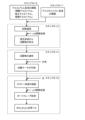
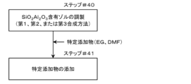
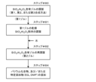
- Process transition diagram showing an overview of the method for synthesizing the SiO 2 Al 2 O 3 -containing sol solution (first synthesis method) in the first embodiment TEM photographs of four types of SiO 2 Al 2 O 3 -containing sol solutions whose solution states are sol, gel, first half sol, and precipitate.
- autoclave treatment processing temperature, processing time
- XRD pattern diagram showing the crystal structure of Comparative Example C1 (comparative dry sample C1D) before initial heat treatment BJH plot diagram showing the pore distribution of the present powder sample S1 and comparative sample C1B after the first heat treatment with a SiO 2 concentration of 3% by mass
- XRD pattern diagram showing the crystal structure after initial heat treatment, first heat treatment, and second heat treatment of S10 Process transition diagram showing an overview of the method for forming a porous alumina film (this formation method) in the seventh embodiment FE-SEM photograph of a porous alumina film of 6.5% BaO-1% SiO 2 Al 2 O 3 formed on the surface of glass cloth and silica cloth Porous 1% SiO 2 Al 2 O 3 formed on the glass plate surface using two types of 1% SiO 2 Al 2 O 3 sol solutions with sol solution concentrations of 2.5% by mass and 3.75% by mass.
- an alkoxysilane solution containing alkoxysilane, water, alcohol, and an inorganic acid is prepared (step #11), and an aluminum compound selected from aluminum nitrate, aluminum chloride, and aluminum sulfate and aluminum containing water are prepared.
- Step #12 an aluminum compound selected from aluminum nitrate, aluminum chloride, and aluminum sulfate and aluminum containing water are prepared.
- Step #13 in a mixed solution obtained by mixing the alkoxysilane solution obtained in step #11 and the aluminum solution obtained in step #12, a precipitate with a silicon compound adsorbed on aluminum hydroxide is precipitated ( Step #13).
- step #13 the precipitate obtained in step #13 is filtered from the mixed solution, and the filtered precipitate is washed with water to prepare a precipitate cake (step #14).
- water was added to the precipitate cake obtained in step #14 to prepare a slurry solution, and the slurry solution was subjected to pH adjustment treatment and then autoclave treatment to form a SiO 2 Al 2 O 3 -containing sol.
- Step #15 a sol solution containing SiO 2 Al 2 O 3 is synthesized.
- step #15 aluminum hydroxide (Al(OH) 3 ) in the slurry solution is partially dehydrated under the temperature and pressure of autoclave treatment to generate boehmite (AlOOH), and the boehmite particles contain silica.
- AlOOH boehmite
- a SiO 2 Al 2 O 3 -containing sol solution is synthesized in which sol particles bound to SiO 2 Al 2 O 3 exist in a highly dispersed state.
- a synthesis method in which a sol solution containing SiO 2 Al 2 O 3 is synthesized after autoclave treatment will be referred to as a first AC (autoclave) method. That is, the first synthesis method corresponds to the first AC method when the aluminum compound is selected from aluminum nitrate, aluminum chloride, and aluminum sulfate.
- the alkoxysilane is preferably tetraalkoxysilane.
- the tetraalkoxysilane is preferably selected from tetramethoxysilane, tetraethoxysilane, tetraisopropoxysilane, and tetra-n-butoxysilane, and in the examples described later, tetraethoxysilane (TEOS) is preferably selected.
- TEOS tetraethoxysilane
- the alcohol methanol, ethanol, n-propanol, isopropanol, etc. are used, and in the examples described later, ethanol is preferably used.
- As the inorganic acid hydrochloric acid, nitric acid, etc. are used, and in the examples described later, hydrochloric acid is preferably used.
- the amount of alkoxysilane in the alkoxysilane solution prepared in step #11, the amount of aluminum compound in the aluminum solution prepared in step #12, and the alkoxysilane solution and aluminum solution mixed in step #13 The mass concentration of SiO 2 to SiO 2 Al 2 O 3 in the SiO 2 Al 2 O 3 -containing sol solution prepared in step #15 is determined by the mixing ratio of ) is determined. Therefore, in order to set the SiO 2 concentration in the SiO 2 Al 2 O 3- containing sol solution to a desired value, the mixing ratio of both solutions is adjusted in step #13 for each amount of preparation in steps #11 and #12. adjusted.
- step #13 after heating the mixed solution to reflux, aqueous ammonia is added dropwise to the mixed solution to adjust the pH, and the mixture is stirred. Hydrolysis of the mixed solution proceeds by the heating under reflux and pH adjustment, and aluminum hydroxide and a silicon compound co-precipitate.
- step #15 the amount of water added to the precipitate cake is adjusted so that the sol solution has a SiO 2 Al 2 O 3 content relative to the total mass of the SiO 2 Al 2 O 3 -containing sol solution after synthesis.
- concentration (mass%) is controlled to be below a certain concentration at which the solution state after autoclave treatment becomes a sol state, and a pH adjustment process is performed on the slurry solution to adjust the pH value of the slurry solution to the same level as the solution after autoclave treatment.
- the pH is controlled within a specific pH range where the state becomes a sol state.
- the total mass of the SiO 2 Al 2 O 3- containing sol solution after synthesis is set to a constant value with respect to the internal capacity of the autoclave used for autoclave treatment, so the sol solution concentration is controlled in steps. This is done by adjusting the amount of alkoxysilane and aluminum compound charged in steps #11 and #12 and the amount of water added to the precipitation cake in step #15.
- the specific concentration changes depending on the SiO 2 concentration and the heating conditions of autoclave treatment (processing temperature, processing time), and the specific pH range is within the range of 2.8 to 7.8. varies depending on the SiO 2 concentration.
- the treatment temperature of the autoclave treatment is set to a specific treatment temperature within the range of 100°C or more and 200°C or less
- the treatment time of the autoclave treatment is set at a time after the autoclave treatment according to the specific treatment temperature.
- the specific time range is within a range of 1 hour or more and 100 hours or less.
- Example 1 in which aluminum nitrate is used as the aluminum compound
- Example 2 in which aluminum chloride is used
- Example 3 in which aluminum sulfate is used will be described in order.
- Example 1 (aluminum compound: aluminum nitrate)
- tetraethoxysilane (TEOS) is used as the alkoxysilane
- ethanol is used as the alcohol
- hydrochloric acid is used as the inorganic acid.
- 7.52 g of ethanol was added to 5 g of TEOS, and the mixture was stirred at room temperature for 5 minutes, then 1.25 g of concentrated hydrochloric acid (37%) was added, and the mixture was further stirred at room temperature for 5 minutes. While stirring this mixed solution, 71.2 g of water was added dropwise and mixed to obtain a transparent and uniform 5.88% TEOS solution (alkoxysilane solution).
- step #12 aluminum nitrate was used as the aluminum compound, and 14.57 g of aluminum nitrate nonahydrate was dissolved in 57.10 g of water to obtain an aluminum nitrate aqueous solution (aluminum solution).
- step #13 1.18 g of the 5.88% TEOS solution obtained in step #11 was added to the aluminum nitrate aqueous solution obtained in step #12, and the resulting homogeneous mixed solution was heated to reflux at 100°C. 28% aqueous ammonia was added dropwise and stirred until the pH reached 9.0. As the ammonia water was added dropwise, aluminum hydroxide and a silicon compound co-precipitated, and a precipitate was deposited in the mixed solution.
- step #14 the mixed solution containing the precipitate was suction-filtered using No. 1 filter paper to separate the precipitate.
- the filtered precipitate was washed with ion-exchanged water at room temperature to obtain a precipitate cake.
- step #15 water was added to the obtained precipitate cake so that the total amount was 80 g, and the mixture was stirred to prepare a slurry solution.
- Nitric acid (60% aqueous solution) was added to this slurry solution until the pH reached 5.0, and autoclave treatment was performed at 150° C. for 15 hours to obtain a 1% SiO 2 Al 2 O 3 -containing sol solution.
- an autoclave comprised of a 100 ml Teflon (registered trademark) container enclosed in a stainless steel jacket was used.
- the total amount of the 1% SiO 2 Al 2 O 3 containing sol solution obtained in step #15 is 80 g, and the 1% SiO 2 Al 2 O 3 powder obtained by drying this sol solution is 2.0 g.
- the sol solution concentration of a total amount of 80 g of sol solution containing 2.0 g of 1% SiO 2 Al 2 O 3 powder is 2.5% by mass.
- the amount of nitric acid (60% aqueous solution) used to adjust the pH of the slurry solution is a small amount of about 400 to 600 ⁇ L, so the total amount of the sol solution containing 1% SiO 2 Al 2 O 3 is approximately equal to that of the slurry solution.
- the amount is 80 g, which is the same as the total amount of the solution.
- the content and structure of the autoclave used in the autoclave treatment of this synthesis method are not limited to the content and structure of the autoclave used in Example 1.
- the content and structure of the autoclave used in the autoclave treatment of this synthesis method are It is sufficient to use an autoclave whose internal capacity corresponds to the total amount of the 2 O 3 -containing sol solution.
- a sol solution containing SiO 2 Al 2 O 3 with a SiO 2 concentration of X mass % and a sol solution concentration of Y mass % will be referred to as an X% SiO 2 Al 2 O 3 Y% sol. Therefore, the 1% SiO 2 Al 2 O 3 -containing sol solution obtained in step #15 is expressed as 1% SiO 2 Al 2 O 3 2.5% sol.
- Example 2 (aluminum compound: aluminum chloride)
- step #12 9.38 g of aluminum chloride (III) hexahydrate was dissolved in 83.24 g of water to obtain an aluminum chloride aqueous solution (aluminum solution).
- a sol solution containing 1% SiO 2 Al 2 O 3 could be synthesized under exactly the same conditions as in Example 1. That is, in Example 2, as in Example 1, a total amount of 80 g of 1% SiO 2 Al 2 O 3 2.5% sol was obtained. Therefore, explanations that overlap with those of the first embodiment will be omitted.
- Example 1 the aluminum nitrate aqueous solution was prepared at a concentration of about 20% by mass (including crystal water), whereas in Example 2, at 20% by mass, the amount of water was too small relative to the amount of precipitation. Since stirring was not sufficient, the aluminum chloride aqueous solution was prepared at a low concentration of about 10% by mass (including crystal water).
- Example 3 (aluminum compound: aluminum sulfate)
- Example 3 similar to Examples 1 and 2, to synthesize a 1% SiO 2 Al 2 O 3 2.5% sol with a total amount of 80 g, in step #12, 6.64 g of aluminum sulfate (anhydrous) It is necessary to dissolve this in 58.58 g of water to obtain an aqueous aluminum sulfate solution (aluminum solution).
- step #15 even if the pH value of the slurry solution is controlled within the same specific pH range as when the aluminum compound is aluminum nitrate, the heating conditions of the autoclave treatment (150°C, 15 hours) are the same as in Example 1.
- Example 1 the aluminum nitrate aqueous solution was prepared at a concentration of about 20% by mass (including crystal water), whereas in Example 3, at 20% by mass, the amount of water was too small relative to the amount of precipitation. Since stirring was not sufficient, the aluminum sulfate aqueous solution was prepared at a low concentration of about 10% by mass.
- the solution state can be changed from the second half sol to the sol state by adjusting the heating conditions during autoclave treatment and increasing the amount of heating, as described later. There is a possibility that
- the solution state after the autoclave treatment in step #15 is determined by the SiO 2 concentration and sol solution concentration of the SiO 2 Al 2 O 3 -containing sol solution after synthesis, and the pH of the slurry solution.
- it can be in six states: sol, first half sol, second half sol, gel, precipitate, and cloudy sol.
- the SiO 2 concentration of the SiO 2 Al 2 O 3 -containing sol solution after synthesis, the sol solution concentration, the pH value of the slurry solution, and the heating conditions for autoclave treatment are collectively referred to as autoclave treatment conditions. do.
- the sol is a transparent solution with a slight whitish tinge, and exhibits a solution state in which light scattering due to the Tyndall phenomenon is confirmed when irradiated with laser light.
- transparent of a sol means that when the sol solution is stored in a colorless and transparent glass container with an inner diameter of about 8 cm, the transparency is such that the letters and figures on the side of the glass container can be visually confirmed through the sol solution from the opposite side. has.
- a gel has a higher viscosity than a sol. Precipitation indicates a state in which a white precipitate and a solution separate when left to stand, and the white precipitate is opaque.
- the first half-sol is an intermediate state in the process from a sol to a gel, in which a portion of the sol solution is gelled, and the gelled portion is transparent.
- the second half sol is opaque because the precipitate is not fully peptized and some of the precipitate remains in the solution.
- step #15 of Example 1 with a SiO 2 concentration of 1% by mass the pH value of the slurry solution was changed to create four types of SiO 2 Al 2 O whose solution states were sol, gel, first half sol, and precipitate. 3- containing sol solutions were prepared, and TEM (transmission electron microscope) observation was performed on these four types of sol solutions.
- a field emission type JEM-2100 manufactured by JEOL Ltd. was used as a transmission electron microscope.
- Figure 2 shows a TEM photograph.
- Each sol solution was diluted with ethanol and observed on a Cu mesh.
- the gel in photo (a) was in a state where needle-like particles with a width of 5 nm and a length of 50 to 100 nm aggregated.
- the heating in the autoclave treatment was insufficient, and some of the precipitates of boehmite with adsorbed silica (boehmite without adsorbed silica when the SiO2 concentration was 0% by mass) were not completely peptized and remained.
- a cloudy sol indicates a state in which the sol becomes cloudy due to excessive heating during the autoclave treatment, resulting in precipitation formation due to growth of sol particles and gel formation due to boehmite polymerization.
- the cloudy sol is distinguished as a solution state different from the first half sol, second half sol, gel, and precipitate.
- the solution state after autoclave treatment is any of the five states other than sol, there is a possibility that a porous alumina film with a certain degree of heat resistance and specific surface area can be formed.
- the solution state is a sol, as described below. Therefore, below, autoclave treatment conditions under which the solution state after autoclave treatment becomes a sol will be discussed.
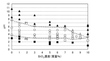
- the results of checking the solution state are shown in FIG. 3 as a scatter diagram.
- the vertical axis of the scatter diagram shows the pH value of the slurry solution, and the horizontal axis shows the SiO 2 concentration.
- the sol is shown as a white circle ⁇
- the gel as a black square ⁇
- the precipitate as a black triangle ⁇
- the first half sol as a white square ⁇
- the second half sol as a white triangle ⁇ .
- the specific pH range (from the lower limit value to the upper limit value) is within the range of 2.8 to 7.8 when the SiO 2 concentration is 0 to 10% by mass. It can be seen that the width (difference between the upper limit and the lower limit) decreases as the SiO 2 concentration increases. It can also be seen that at the same SiO 2 concentration, gelation occurs when the pH value is lower than a specific pH range, and precipitation occurs when the pH value is greater than the specific pH range.
- the solution state maintains a sol state when the pH value is within a specific pH range (3.84 to 7.74), but the pH value Since a transparent gel was formed in the pH range lower than 3.84, it is considered that the acid catalyst promoted the polymerization of the sol and led to gelation.
- the solution state can be changed to a sol. There is a possibility that it can be done. Therefore, even in a sol solution containing SiO 2 Al 2 O 3 to which silica is added, the specific pH range shown in FIG. 3 may be extended downward by relaxing the heating conditions.
- silica sol Since the isoelectric point of silica sol is pH 1 to 1.5, in the neutral region where boehmite sol exists, silica will be dispersed in the liquid with its surface negatively charged. Boehmite is positively charged near neutrality, and silica is thought to be electrostatically bonded to boehmite. Therefore, the reason why the upper limit of the specific pH range decreases as the SiO 2 concentration increases in FIG. 3 is considered to be due to the influence of silica sol.
- the pH value of the slurry solution in step #15 is determined by P0 and P1 given by the above calculation formula.
- a pH adjustment process can be performed so that the pH falls within a specific pH range.
- the pH value of the slurry solution was set to pH 5.0, which is the same as in Example 1, when the SiO 2 concentration was in the range of 0% to 7% by mass, and when the SiO 2 concentration was in the range of 8% to 10% by mass. In the range shown in FIG. 3, the pH value was set to a specific pH range in which the solution state becomes a sol. Furthermore, the heating conditions for the autoclave treatment were the same as in Example 1 above, at 150°C for 15 hours, and the same aluminum nitrate as in Example 1 was used as the aluminum compound.
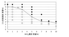
- the results of checking the solution state are shown in FIG. 4 as a scatter diagram.
- the vertical axis of the scatter diagram shows the sol solution concentration (mass %), and the horizontal axis shows the SiO 2 concentration.
- the sol is indicated by a white circle ⁇ , and the second half sol is indicated by a black circle ⁇ .
- SiO 2 concentration increases, the amount of SiO 2 that is not peptized by autoclaving increases, and SiO 2 adsorbs to the precipitated surface of aluminum hydroxide, making it difficult for aluminum hydroxide to peptize.
- the specific concentration decreases as the SiO 2 concentration increases.
- the heating conditions of the autoclave treatment can be appropriately adjusted to reduce the heating amount.
- the solution state may become a sol state.
- the heating condition of the autoclave treatment is 150° C. for 15 hours
- the SiO 2 concentration is X (mass%)
- the amount of alkoxysilane and aluminum compound charged in steps #11 and #12 and the amount of water added to the precipitate cake in step #15 are adjusted so that the sol solution concentration is equal to or less than the specific concentration Y1 given by the above calculation formula.
- the specific concentration Y1 is 0.63% by mass or less. Please pay attention to this point.
- the results of checking the solution state are shown in Table 1 below and the scatter diagram in FIG. 5.
- the vertical axis of the scatter diagram shows the processing time, and the horizontal axis shows the processing temperature.
- the sol is indicated by a white circle
- the second half sol is indicated by a black circle
- the cloudy sol is indicated by an x.
- solization was achieved in 1 hour at a treatment temperature of 200°C, 15 to 48 hours at a treatment temperature of 150°C, and 24 to 100 hours at a treatment temperature of 100°C. From the above results, when increasing the amount of heating by increasing at least one of the treatment temperature and treatment time, the solution state transitions from a sol to a cloudy sol, and the amount of heating is decreased by decreasing at least one of the treatment temperature and treatment time. It can be seen that when this happens, the solution state transitions from a sol to a second half-sol.
- the heating conditions for turning the solution state into a sol are, for example, a processing temperature of 150°C and a processing time of 15 to 48 hours
- the processing temperature is increased from 150°C while maintaining the sol in the solution state
- it is sufficient to shorten the treatment time from 15 to 48 hours but conversely, when lowering the treatment temperature from 150°C, in order to suppress the decrease in the amount of heating,
- the treatment temperature should be lowered from 150°C in order to suppress the increase in the amount of heating.
- the treatment time is to be shorter than 15 to 48 hours, on the other hand, it is understood that the treatment temperature should be raised from 150° C. in order to suppress the decrease in the amount of heating.
- Heating conditions for autoclave treatment (2) From Table 1 above, if the sol solution concentration becomes higher than the specific concentration under a certain heating condition and the solution state becomes a second half sol, heating should be performed by increasing at least one of the processing temperature and processing time at the sol solution concentration. It is expected that by increasing the amount, the solution state can become a sol.
- three types of slurry solutions with different SiO 2 concentrations and sol solution concentrations were autoclaved at a treatment temperature of 150°C and treatment time was changed in three or five ways within the range of 2 to 100 hours. A total of 13 samples (samples 14 to 26, slurry solutions) were subjected to autoclave treatment, and the state of the solution after autoclave treatment was visually confirmed.
- Samples 14 to 18 are for 1% SiO 2 Al 2 O 3 3.75% sol with a SiO 2 concentration of 1% by mass and a sol solution concentration of 3.75% by mass;
- Sample 21 is for a 1% SiO 2 Al 2 O 3 10% sol with a SiO 2 concentration of 1% by mass and a sol solution concentration of 10% by mass, and samples 22 to 26 have a SiO 2 concentration of 7% by mass and a sol solution concentration of 6% by mass. This is for a 7% SiO 2 Al 2 O 3 6% sol.
- Each sample was prepared using aluminum nitrate as the aluminum compound as in Example 1, and in step #15, the pH value of the slurry solution was adjusted to about pH 5.0 using nitric acid.
- the scatter diagram in FIG. 6 shows the solution states of samples 14 to 21 after autoclaving. Further, Table 2 below shows the solution states of Samples 22 to 26 after autoclaving.
- the vertical axis of the scatter diagram shows the processing time, and the horizontal axis shows the sol solution concentration.
- the sol is indicated by a white circle ⁇
- the second half sol is indicated by a black circle ⁇
- the cloudy sol is indicated by an x
- the gel is indicated by a black square ⁇ .
- the solution state after autoclaving at 150°C for samples 14 to 18 with a sol solution concentration of 3.75% by mass was a second half sol when the treatment time was 2 hours, but after the treatment time was 15 hours. After treatment time of 72 hours and 100 hours, it became a sol, and furthermore, after a treatment time of 72 hours and 100 hours, it became a cloudy sol.
- the solution state of Samples 19 to 21 with a sol solution concentration of 10% by mass after autoclaving at 150°C was a second half sol at a treatment time of 15 hours, but became a sol at a treatment time of 24 hours, and further After 48 hours, it became a gel.
- the autoclave treatment for a long time progressed the peptization and the solution state became a sol. If the treatment time was further extended, the solution state transitioned to a gel. I found out that it does.
- the processing time range in which the sol state can be maintained is narrower than when the sol solution concentration is 3.75% by mass, and it is necessary to appropriately control the processing time.
- the treatment time and treatment that can change the solution state to a sol state As mentioned above, from the results of the solution state shown in Figures 4 to 6, Tables 1 and 2, as at least one of the SiO 2 concentration and the sol solution concentration becomes lower or higher, the treatment time and treatment that can change the solution state to a sol state. It can be seen that as the temperature range expands or contracts and both the SiO 2 concentration and the sol solution concentration increase, there is no longer a range of processing time and processing temperature in which the solution state can change to the sol state. Therefore, the SiO 2 concentration and the sol solution concentration each have an upper limit of about 10% by mass, and if one is set high, the other needs to be set low within a range where the solution state can become a sol state. However, when viewed as a whole, it can be said that there is an extremely high degree of freedom in combining the SiO 2 concentration, the sol solution concentration, the autoclave treatment time, and the treatment temperature that can change the solution state to a sol state.
- the heating conditions are not limited to the above-mentioned 150° C. and 15 hours, and the processing temperature and processing time may be changed so as to suppress the increase/decrease in the amount of heating, as described above.
- the method for synthesizing the SiO 2 Al 2 O 3 powder of Comparative Example C1 is the precipitation method (Patent Document 6), which is one of the methods for synthesizing porous alumina to which silica and barium oxide are added, as disclosed in Patent Document 6 above. (see FIG. 16), this corresponds to the case where silica-added porous alumina is synthesized without adding barium oxide.
- Patent Document 6 the precipitation method for Comparative Example C1 and Comparative Examples C2 and C7 described below will be appropriately referred to as a "precipitation method" regardless of whether barium oxide is added or not.
- Comparative Example C1 was a powder sample, a powder sample was used instead of a coated film in order to easily examine changes in heat resistance due to differences in SiO 2 concentration.
- the steps up to the preparation of the precipitate cake are the same as steps #11 to #14 of the first synthesis method.
- the obtained precipitate cake was dried at 150°C, then ground into powder, and calcined in air at 1000°C for 5 hours (initial heat treatment) to form SiO 2 Al 2 O 3 powder ( A comparative sample C1A) was prepared.
- Comparative sample C1A is comparative example C1 in which only the initial heat treatment was performed and neither the first heat treatment nor the second heat treatment was performed.
- the first heat treatment the temperature was raised from room temperature to 1200°C at a rate of 10°C/min, and then held at 1200°C for 5 hours.
- the second heat treatment the temperature was raised from room temperature to 1200°C at a rate of 10°C/min, and then held at 1200°C for 30 hours.
- this sample S1A a sol solution containing SiO 2 Al 2 O 3 obtained through step #15 following steps #11 to #14 of the first synthesis method was dried at 150°C, and then pulverized. The powder was made into a powder, and then fired in air at 1000° C. for 5 hours (initial heat treatment) to produce SiO 2 Al 2 O 3 powder (this sample S1A). Furthermore, this sample S1B, which is obtained by adding a first heat treatment at 1200°C for 5 hours to this sample S1A, and this sample S1C, which is obtained by adding a second heat treatment at 1200°C for 30 hours to this sample S1A, are processed as necessary. It was made by This sample S1A is a powder sample S1 that was subjected to only the initial heat treatment and neither the first heat treatment nor the second heat treatment was performed.
- step #13 In producing the present samples S1A to S1C and comparative samples C1A to C1C, aluminum nitrate was used as the aluminum compound.
- the specific processing contents of steps #11 to #15 are as explained in Example 1 when the SiO 2 concentration is 1% by mass, and when the SiO 2 concentration is other than 1% by mass, the set value of the SiO 2 concentration is The mixing ratio of the aluminum nitrate aqueous solution and the 5.88% TEOS solution in step #13 was adjusted accordingly.
- the specific surface area, pore distribution, and total pore volume were measured, and the crystal structure was analyzed by X-ray diffraction (XRD) for each sample of the present powder sample S1 and comparative example C1. Also in the evaluation of heat resistance in the second to seventh embodiments, measurements of the specific surface area and the like and XRD analysis were performed as necessary. Note that the specific surface area of the sample was used as an index of heat resistance.
- the specific surface area was measured by the nitrogen adsorption BET method using a fully automatic gas adsorption measurement (BELSORP-max manufactured by Microtrac BEL).
- the pore distribution and total pore volume were measured by the BJH method using a fully automatic gas adsorption measurement (BELSORP-max manufactured by Microtrac BEL).
- the XRD pattern of the crystal structure was measured using an X-ray diffraction device (ULTIMA III manufactured by Rigaku Corporation) by irradiating Cuk ⁇ with a two-dimensional high-speed detector.
- Figure 7 shows the present sample S1A, which was prepared by changing the SiO 2 concentration in seven ways: 0% by mass, 1% by mass, 3% by mass, 5% by mass, 8% by mass, 9% by mass, and 10% by mass.
- the measurement results of each specific surface area of S1B and present sample S1C are shown.
- FIG. 8 shows comparative sample C1A, comparative sample C1B, and comparative sample C1C ( The measurement results of each specific surface area of a total of 15 comparative examples C1) are shown.
- the vertical axis shows the specific surface area (m 2 /g)
- the horizontal axis shows the SiO 2 concentration (mass %).
- the specific surface area of both powder sample S1 and comparative example C1 increases as the SiO 2 concentration increases. ing. Comparing the specific surface areas of the present sample S1A with a SiO 2 concentration of 3% by mass and the comparative sample C1A, the specific surface area of the present sample S1A is 175 m 2 /g, and that of the comparative sample C1A is 165 m 2 /g, which is approximately The same level of heat resistance was obtained.
- the specific surface area of the comparative sample C1A increases as the SiO 2 concentration increases, whereas the specific surface area of the present sample increases.
- the specific surface area of S1A hardly increased. Comparing the specific surface areas of the present sample S1A with a SiO 2 concentration of 10% by mass and the comparative sample C1A, the specific surface area of the present sample S1A is 201 m 2 /g, the specific surface area of the comparative sample C1A is 227 m 2 /g, and the specific surface area of the present sample S1A is 201 m 2 /g. Sample S1A shows a slightly lower specific surface area.
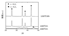
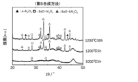
- FIG. 9 shows XRD patterns showing the crystal structure after each heat treatment in this sample S1A, this sample S1B, and this sample S1C with an SiO 2 concentration of 1% by mass.
- FIG. 10 shows XRD patterns showing the crystal structure after each heat treatment in Comparative Sample C1A, Comparative Sample C1B, and Comparative Sample C1C with SiO 2 concentration of 1% by mass.
- FIG. 11 shows an XRD pattern showing the crystal structure of a pre-heat-treated sample (main dry sample S1D) of the present powder sample S1 which has not been subjected to initial heat treatment after drying the SiO 2 Al 2 O 3- containing sol solution at 150°C. shows.
- FIG. 12 shows an XRD pattern showing the crystal structure of a pre-heat-treated sample (comparative dry sample C1D) of Comparative Example C1 which was not subjected to initial heat treatment after drying the precipitate cake at 150°C.
- Comparative Example C1 using the precipitation method completely undergoes a phase transition to ⁇ -Al 2 O 3 in the first heat treatment (1200°C for 5 hours) (Comparative Sample C1B).
- This powder sample S1 which was subjected to the autoclave treatment, did not undergo a complete phase transition to the ⁇ phase even during the second heat treatment (1200° C. for 30 hours). This is because, as shown in the XRD patterns of the main dry sample S1D and the comparative dry sample C1D in Figures 11 and 12, in the main dry sample S1D, the autoclave treatment promoted the production of boehmite and developed small fibrous particles.
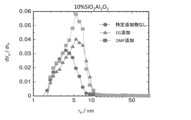
- FIG. 13 shows the pore distribution (BJH plot) of the present sample S1B and the comparative sample C1B, which were subjected to the first heat treatment (1200° C. for 5 hours) with a SiO 2 concentration of 3% by mass.
- FIG. 14 shows the pore distribution (BJH plot) of the present sample S1B and the comparative sample C1B, which were subjected to the first heat treatment with an SiO 2 concentration of 10% by mass.
- circles ( ⁇ ) indicate the pore distribution of the present sample S1B
- triangles ( ⁇ ) indicate the pore distribution of the comparative sample C1B
- the vertical axis represents the differential pore volume dV p /dr p ( m 3 /g/nm)
- the horizontal axis represents the pore diameter r p (nm).
- Table 3 shows the specific surface area (m 2 /g) and total pore volume (cm 3 /g) of the present sample S1B and comparative sample C1B with SiO 2 concentrations of 3% by mass and 10% by mass.
- Table 4 shows the specific surface areas (m 2 /g) of samples S1A to S1C in which the aluminum compounds are aluminum nitrate, aluminum chloride, and aluminum sulfate.
- six types of sol solutions were prepared by changing the pH value of the slurry solution in six ways through the pH adjustment process for the slurry solution in step #15 in the same manner as this powder sample S1. was prepared. Then, six types of powder samples SA were prepared by drying and firing the six types of sol solutions through initial heat treatment at 1000°C for 5 hours, and further, for the six types of powder samples S, the first heat treatment at 1200°C for 5 hours was performed. Six types of powder samples SB, which were each subjected to heat treatment, and six types of powder samples SC, which were each subjected to a second heat treatment at 1200°C for 30 hours, were prepared for six types of powder samples SA, and a total of 18 types of slurry were prepared. Powder samples with different solution pH values and heat treatment conditions were prepared.
- Table 5 shows the measurement results of the specific surface area (m 2 /g) of the six types of powder samples SA, six types of powder samples SB, and six types of powder samples SC.
- both the specific surface area and total pore volume tend to increase in the order of solution state: gel, sol, and precipitate.
- the specific surface area and total pore volume when the solution state is a sol are slightly inferior to those when the solution state is a precipitate, but as explained in the seventh embodiment below, the fixation of the coating film to the base material is When considered, a solution state other than a sol has poor adhesion to the surface of a substrate and is unsuitable for forming a coating film.
- Steps #21 to #25 are basically the same processing contents as steps #11 to #15 of the first synthesis method shown in FIG. 1, but in the second synthesis method, the aluminum compound is sodium aluminate, It is different from aluminum nitrate, aluminum chloride, and aluminum sulfate used as aluminum compounds in the first synthesis method.
- the second synthesis method is a synthesis method in which a sol solution containing SiO 2 Al 2 O 3 is synthesized after autoclave treatment, and corresponds to the first AC method when the aluminum compound is sodium aluminate. .
- steps #22, #23, #24, and #25 differ in some details from steps #12 to #15 of the first synthesis method.
- Step #21 is the same as step #11 of the first synthesis method.
- step #22 differs from step #12 of the first synthesis method only in the aluminum compound used. Therefore, duplicate explanations regarding steps #21 and #22 will be omitted.
- the method for adjusting the SiO 2 concentration and the method for adjusting the sol solution concentration are also the same as in the first synthesis method, and redundant explanations will be omitted.
- step #23 a precipitate of silicon compounds adsorbed on aluminum hydroxide is precipitated in a mixed solution obtained by mixing the alkoxysilane solution obtained in step #21 and the aluminum solution obtained in step #22. This is the same as step #13 of the first synthesis method.
- step #21 A mixed solution is prepared by mixing with the alkoxysilane solution obtained.
- a precipitate adsorbed with a silicon compound is precipitated on the precipitate of aluminum hydroxide precipitated during the pH adjustment treatment of the aluminum solution.
- step #23 is different from step #13 in that in step #13, the mixed solution is heated under reflux and pH adjusted, whereas in step #23, these treatments are performed on the aluminum solution. They are different.
- Step #24 is the same as step #14 of the first synthesis method in that the precipitate obtained in step #23 is filtered from the mixed solution and the filtered precipitate is washed with water to prepare a precipitation cake. It is. However, in the example of the first synthesis method, the filtered precipitate is washed with water at room temperature, but in the example of the second synthesis method, the filtered precipitate is washed with water. Step #24 differs from step #14 in that the object is washed with ion-exchanged water at, for example, 60°C. If sodium contained in the aluminum compound is present in the SiO 2 Al 2 O 3- containing sol solution synthesized in step #25, sintering of alumina will occur when the sol solution is dried and sintered. Therefore, in step #24, hot water at 60° C. is used to wash the filtered precipitate to improve washing performance and remove the sodium from the precipitate.
- step #25 water is added to the precipitate cake obtained in step #24 to prepare a slurry solution, and the slurry solution is subjected to pH adjustment treatment and then autoclaved to form SiO 2 Al 2 O.
- the preparation of the 3- containing sol solution is the same as step #15 of the first synthesis method. Furthermore, it is the same as step #15 of the first synthesis method that sol particles in which silica is bonded to boehmite particles are present in a highly dispersed state in the prepared sol solution containing SiO 2 Al 2 O 3 .
- the sol solution concentration (mass %) is controlled to a specific concentration or less at which the solution state after autoclaving becomes a sol state, and the slurry solution is subjected to a pH adjustment process.
- the point that the pH value of the slurry solution is controlled within a specific pH range such that the solution state after autoclaving becomes a sol state is also the same as step #15 of the first synthesis method.
- the processing temperature of the autoclave treatment is set to a specific processing temperature within the range of 100°C or more and 200°C or less
- the processing time of the autoclave processing is set to a time period after the autoclave treatment according to the specific processing temperature.
- the point that the solution state is set within a specific time range where the solution state becomes a sol state, and the point that the specific time range is within a range of 1 hour or more and 100 hours or less are also the same as step #15 of the first synthesis method.
- the specific concentration changes depending on the SiO 2 concentration and the heating conditions of autoclave treatment (processing temperature, processing time), and the specific pH range is SiO 2 within the range of 1.0 to 6.2. Varies depending on concentration.
- the specific concentration and specific pH range in step #25 are different from those in step #15 of the first synthesis method.
- Example of second synthesis method Example 4 of steps #21 to #25 in the case of synthesizing a sol solution containing SiO 2 Al 2 O 3 with a SiO 2 concentration of 1% by mass will be described below.
- Sodium aluminate is used as the aluminum compound.
- step #21 a transparent and uniform 5.88% TEOS solution (alkoxysilane solution) was obtained using exactly the same procedure as step #11 of Example 1.
- step #22 3.57 g of sodium aluminate was dissolved in 66.56 g of water to obtain an aqueous sodium aluminate solution (aluminum solution).
- step #23 the sodium aluminate aqueous solution obtained in step #22 was heated to reflux, and nitric acid was added dropwise to the solution and stirred until the pH reached 8.0. A precipitate of aluminum hydroxide was deposited as the nitric acid was added dropwise. Subsequently, 1.18 g of the 5.88% TEOS solution obtained in step #21 was added dropwise to the sodium aluminate aqueous solution in which the aluminum hydroxide precipitate had precipitated, and the mixture was stirred at room temperature for 30 minutes. As a result, a precipitate in which a silicon compound was adsorbed to aluminum hydroxide was obtained in a mixed solution of a sodium aluminate aqueous solution and a TEOS solution.
- step #24 the mixed solution containing the precipitate obtained in step #23 was suction-filtered using No. 1 filter paper to filter out the precipitate.
- the filtered precipitate was washed with ion-exchanged water at 60°C to obtain a precipitate cake.
- step #25 water was added to the obtained precipitate cake so that the total amount was 80 g, and the mixture was stirred to prepare a slurry solution.
- Nitric acid (60% aqueous solution) was added to this slurry solution until the pH reached 3.0, and autoclave treatment was performed at 150° C. for 15 hours to obtain a 1% SiO 2 Al 2 O 3 -containing sol solution.
- an autoclave with an internal capacity of 100 ml was used as in Examples 1 to 3.
- the total amount of the 1% SiO 2 Al 2 O 3 containing sol solution obtained in step #25 is 80 g, and the 1% SiO 2 Al 2 O 3 powder obtained by drying this sol solution is 2.0 g.
- the sol solution concentration of a total amount of 80 g of sol solution containing 2.0 g of 1% SiO 2 Al 2 O 3 powder is 2.5% by mass. Therefore, the 1% SiO 2 Al 2 O 3 -containing sol solution obtained in step #25 is a 1% SiO 2 Al 2 O 3 2.5% sol.
- the amount of nitric acid (60% aqueous solution) used to adjust the pH of the slurry solution was very small as in the case of the first synthesis method, so the total amount of the sol solution containing 1% SiO 2 Al 2 O 3 was The amount is approximately 80 g, which is the same as the total amount of the slurry solution.
- the solution state after the autoclave treatment in step #25 is based on the SiO 2 concentration and sol solution concentration of the SiO 2 Al 2 O 3 -containing sol solution after synthesis, and the pH of the slurry solution.
- it can be in six states: sol, first half sol, second half sol, gel, precipitate, and cloudy sol. This point is the same as the first synthesis method.
- the above-mentioned six solution states have already been explained in "[3] Examination of autoclave treatment conditions for the first synthesis method" above, so a redundant explanation will be omitted.
- the results of checking the solution state are shown in FIG. 16 as a scatter diagram.
- the vertical axis of the scatter diagram shows the pH value of the slurry solution, and the horizontal axis shows the SiO 2 concentration.
- the sol is shown as a white circle ⁇
- the gel as a black square ⁇
- the precipitate as a black triangle ⁇
- the first half sol as a white square ⁇ .
- no second half sol was observed.
- the specific pH range (from the lower limit value to the upper limit value) is within the range of 1.0 to 6.2 when the SiO 2 concentration is 0 to 5% by mass, and the It can be seen that it decreases as it increases. Further, as in the first synthesis method, it can be seen that at the same SiO 2 concentration, gelation occurs when the pH value is smaller than a specific pH range, and precipitation occurs when the pH value is larger than the specific pH range.
- the solution state maintains a sol state when the pH value is within a specific pH range (2.07 to 6.15), but the pH value Since a transparent gel was formed in the pH region lower than 2.07, it is considered that the acid catalyst promoted the polymerization of the sol and led to gelation.
- the solution state can be changed to a sol. There is a possibility that it can be done. Therefore, even in a sol solution containing SiO 2 Al 2 O 3 to which silica is added, the specific pH range shown in FIG. 16 may be extended downward by relaxing the heating conditions.
- silica sol Since the isoelectric point of silica sol is pH 1 to 1.5, in the neutral region where boehmite sol exists, silica sol will be dispersed in the liquid with its surface negatively charged. Boehmite is positively charged near neutrality, and silica is thought to be electrostatically bonded to boehmite. Therefore, similarly to the case of the first synthesis method, the reason why the upper limit value of the specific pH range decreases as the SiO 2 concentration increases in FIG. 16 is considered to be due to the influence of silica sol.
- the pH value of the slurry solution is determined by P0 and P1 given by the above calculation formula.
- a pH adjustment process can be performed so that the pH falls within a specific pH range.
- the results of checking the solution state are shown in FIG. 17 as a scatter diagram.
- the vertical axis of the scatter diagram shows the sol solution concentration (mass %), and the horizontal axis shows the SiO 2 concentration.
- the sol is indicated by a white circle ⁇ , and the second half sol is indicated by a black circle ⁇ .
- the heating conditions of the autoclave treatment must be appropriately adjusted. If the amount of heating is increased through adjustment, the solution state may become a sol state.
- the heating condition of the autoclave treatment is 150° C. for 15 hours
- the SiO 2 concentration is X (mass%)
- the amounts of alkoxysilane and sodium aluminate to be charged in steps #21 and #22 and the amount of water added to the precipitate cake in step #25 so that the sol solution concentration is equal to or less than the specific concentration Y1 given by the above calculation formula. can be adjusted.
- the heating conditions are not limited to the above-mentioned 150°C for 15 hours, and the treatment temperature and treatment time may be changed so as to suppress the increase/decrease in the amount of heating, as explained in the first synthesis method. Also good.
- Comparative Example C2 is a powder sample
- a powder sample is used instead of a coated film in order to easily examine changes in heat resistance due to differences in SiO 2 concentration.
- the steps up to the preparation of the precipitate cake are the same as steps #21 to #24 of the second synthesis method.
- the resulting precipitate cake was dried at 150°C, then ground into powder, and calcined in air at 1000°C for 5 hours (initial heat treatment) to form SiO 2 Al 2 O 3 powder (comparative sample).
- C2A comparative sample C2B, which is a first heat treatment of 1200°C for 5 hours added to comparative sample C2A
- comparative sample C2C which is added a second heat treatment of 1200°C 30 hours to comparative sample C2A, are prepared as necessary. It was made by
- a sol solution containing SiO 2 Al 2 O 3 obtained through step #25 following steps #21 to #24 of the second synthesis method was dried at 150°C, and then pulverized. This was made into a powder, and then fired in air at 1000° C. for 5 hours (initial heat treatment) to produce SiO 2 Al 2 O 3 powder (this sample S2A). Furthermore, this sample S2B, which was added to this sample S2A with a first heat treatment of 1200°C for 5 hours, and this sample S2C, which was added with a second heat treatment of 1200°C for 30 hours to this sample S2A, were added as necessary. It was made by
- FIG. 18 shows XRD patterns showing the crystal structures of Sample S2A, Sample S2B, and Sample S2C with an SiO 2 concentration of 1% by mass after each heat treatment.
- FIG. 19 shows XRD patterns showing the crystal structures of Comparative Sample C2A, Comparative Sample C2B, and Comparative Sample C2C with a SiO 2 concentration of 1% by mass after each heat treatment.
- Figure 20 shows sample S2A, sample S2B, and sample S2C (12 samples in total) prepared by changing the SiO 2 concentration in four ways: 0% by mass, 1% by mass, 3% by mass, and 5% by mass.
- the measurement results of each specific surface area of powder sample S2) are shown.
- FIG. 21 shows comparative sample C2A, comparative sample C2B, and comparative sample C2C (12 comparisons in total) prepared by changing the SiO 2 concentration in four ways: 0% by mass, 1% by mass, 3% by mass, and 5% by mass.
- the measurement results of each specific surface area of Example C2) are shown.
- the vertical axis of each graph represents the specific surface area (m 2 /g)
- the horizontal axis represents the SiO 2 concentration (mass %).
- the specific surface areas of Comparative Sample C2A, Comparative Sample C2B, and Comparative Sample C2C after the initial, first, and second heat treatments are as follows when the aluminum compound is aluminum nitrate (see FIG. 8):
- the specific surface area is approximately the same as that of comparative sample C1A, comparative sample C1B, and comparative sample C1C after the first and second heat treatments.
- the specific surface area of sample S2B and sample S2C after the first and second heat treatments is the same as that of the sample after the first and second heat treatments when the aluminum compound is aluminum nitrate (see FIG. 7).
- the specific surface area is approximately the same as that of S1B and this sample S1C.
- the SiO 2 concentration is 1% by mass or more and the specific surface area is approximately constant. This is considered to be due to the decrease in total pore volume accompanying the drying treatment of the sol solution, as in the case where the aluminum compound is aluminum nitrate.
- step #36 the alkoxy prepared in step #31 is added to the silica-free (SiO 2 concentration 0 mass %) Al 2 O 3 -containing sol solution synthesized through steps #32 to #35.
- a sol solution containing SiO 2 Al 2 O 3 is synthesized by directly adding the silane solution.
- the third synthesis method is different from the first and second synthesis methods, which are the first AC methods, in which a SiO 2 Al 2 O 3 -containing sol solution is synthesized after the autoclave treatment, and the sol solution containing SiO 2 Al 2 O 3 is synthesized after the autoclave treatment in step #35.
- a 2 O 3 containing sol solution is synthesized.
- step #31 an alkoxysilane solution containing alkoxysilane, water, alcohol, and an inorganic acid is prepared, and in step #32, an alkoxysilane solution is selected from aluminum nitrate, sodium aluminate, aluminum chloride, and aluminum sulfate. Prepare an aluminum solution containing an aluminum compound and water. Since the alkoxysilane solution obtained in step #31 is used in step #36, step #31 only needs to be performed before step #36.
- step #33 a precipitate of aluminum hydroxide to which no silicon compound is adsorbed is precipitated from the aluminum solution without preparing a mixed solution of an alkoxysilane solution and an aluminum solution. Therefore, step #33 is significantly different from steps #13 and #23 of the first and second synthesis methods, in which a precipitate with a silicon compound adsorbed on aluminum hydroxide is precipitated.
- step #34 the precipitate obtained in step #33 is filtered from the aluminum solution, and the filtered precipitate is washed with water to prepare a precipitate cake.
- step #35 water is added to the precipitate cake obtained in step #34 to prepare a slurry solution, and the slurry solution is subjected to pH adjustment treatment, and then autoclaved to remove silica.
- a sol solution containing Al 2 O 3 is prepared.
- aluminum hydroxide in the slurry solution is partially dehydrated to produce boehmite, and an Al 2 O 3 -containing sol solution in which the boehmite particles are present in a highly dispersed state as sol particles is prepared.
- step #36 the alkoxysilane solution prepared in step #31 is mixed with the Al 2 O 3 -containing sol solution prepared in step # 35 and stirred to form a SiO 2 Al 2 O 3 -containing sol solution.
- a sol solution containing SiO 2 Al 2 O 3 is synthesized in which sol particles in which silica particles are adsorbed to boehmite particles exist in a highly dispersed state.
- Step #31 is the same as steps #11 and #21 of the first and second synthesis methods
- step #32 is the same as steps #11 and #21 of the first and second synthesis methods
- step #34 is the same as steps #14 and #24 of the first and second synthesis methods, except that there is no silica present in the precipitate cake. Therefore, explanations that overlap with the first and second synthesis methods will be omitted.
- step #35 water is added to the precipitate cake obtained in step #34 to prepare a slurry solution, and the slurry solution is subjected to pH adjustment treatment, and then autoclaved to prepare a slurry solution containing Al 2 O 3 .
- the preparation of the sol solution is the same as steps #15 and #25 of the first and second synthesis methods, except that silica is not present in the prepared sol solution.
- the fact that boehmite particles exist in a highly dispersed state as sol particles in the prepared Al 2 O 3 -containing sol solution is also different from the first and second synthesis methods, except that silica is not bonded to boehmite particles. This is the same as steps #15 and #25.
- step #33 the aluminum solution is heated to reflux, and then nitric acid is added dropwise to perform pH adjustment treatment, followed by stirring. Hydrolysis of the aluminum solution proceeds by the heating under reflux and pH adjustment, and a precipitate of aluminum hydroxide is precipitated.
- step #35 the amount of water added to the precipitate cake is adjusted so that the sol solution concentration (mass% ) is controlled to a specific concentration below which the solution state after autoclave treatment becomes a sol state, and the pH value of the slurry solution is controlled to a value such that the solution state after autoclave treatment becomes a sol state by performing pH adjustment processing on the slurry solution.
- the pH is controlled within a specific pH range.
- the sol solution concentration is controlled in step #32. This is done by adjusting the amount of aluminum compound charged in step #35 and the amount of water added to the precipitation cake in step #35.
- the specific concentration in step #35 is the specific concentration of SiO 2 concentration of 0 mass % (no silica added) in step #15 of the first synthesis method, or the specific concentration of step #25 of the second synthesis method, depending on the aluminum compound used.
- the SiO 2 concentration is a specific concentration of 0% by mass.
- the specific pH range in step #35 is the specific pH range of SiO 2 concentration of 0% by mass in step #15 of the first synthesis method, or the specific pH range of SiO 2 concentration of 0% by mass in step # 25 of the second synthesis method, depending on the aluminum compound used. This results in a specific pH range with a concentration of 0% by mass.
- step #35 in the third synthesis method, unlike the first and second synthesis methods, setting the sol solution concentration and adjusting the pH of the slurry solution are easily carried out without being constrained by the SiO 2 concentration. be able to.
- autoclave treatment can be performed under the conditions of SiO 2 concentration 0 mass %, which has the highest specific concentration and the widest specific pH range (Fig. 3, Fig. 4, 16 and 17), compared to the first AC method, it is easier to prepare a sol solution containing SiO 2 Al 2 O 3 whose solution state becomes a sol, and furthermore, it is easier to prepare a sol solution containing SiO 2 Al 2 O 3 with a high solution concentration. It becomes possible to prepare a sol solution.
- the first AC method is divided into the first synthesis method and the second synthesis method depending on the aluminum compound, and step #13 of the first synthesis method and step #23 of the second synthesis method include some treatments (heating reflux and pH There were slight differences in the adjustment).
- step #13 of the first synthesis method and step #23 of the second synthesis method include some treatments (heating reflux and pH There were slight differences in the adjustment).
- step #33 corresponding to steps #13 and #23 there is no step of preparing a mixed solution of an alkoxysilane solution and an aluminum solution.
- the processing contents are the same regardless of whether aluminum, aluminum sulfate, or sodium aluminate is used.
- Example 5 in which aluminum nitrate is used as the aluminum compound will be described below.
- step #31 a transparent and uniform 5.88% TEOS solution (alkoxysilane solution) was obtained using the same procedure as step #11 of Example 1.
- step #32 an aqueous aluminum nitrate solution (aluminum solution) was obtained in the same manner as in step #12 of Example 1.
- the amount of water added to the aluminum solution is increased from the amount of water in step #12 of Example 1 by the same amount as the TEOS solution added in Step #13 of Example 1. is preferable.
- the total amount of the aluminum solution during precipitate precipitation in step #33 becomes the same as the total amount of the mixed solution during precipitate precipitation in step #13 of Example 1.
- step #33 the aluminum nitrate aqueous solution obtained in step #32 was heated to reflux and pH adjusted in the same manner as in step #13 of Example 1, without adding the 5.88% TEOS solution, and aluminum nitrate was A precipitate of aluminum hydroxide was deposited in the aqueous solution.
- step #34 a precipitate cake was obtained using exactly the same procedure as step #14 of Example 1. Subsequently, in Step #35, a 0% SiO 2 Al 2 O 3 -containing sol solution (Al 2 O 3 -containing sol solution) to which silica was not added was obtained in exactly the same manner as in Step # 15 of Example 1.
- the total amount of the Al 2 O 3 -containing sol solution obtained in step #35 is 80 g, and the amount of Al 2 O 3 powder obtained by drying this sol solution is 1.98 g.
- the sol solution concentration of a total amount of 80 g of sol solution containing 1.98 g of Al 2 O 3 powder is 2.475% by mass.
- step #36 1.18 g of the 5.88% TEOS solution prepared in step #31 was mixed with the Al2O3 - containing sol solution obtained in step #35, and then stirred at room temperature for 5 minutes. , a SiO 2 Al 2 O 3 -containing sol solution (1% SiO 2 Al 2 O 3 2.46% sol) with a SiO 2 concentration of 1% by mass and a sol solution concentration of 2.46% by mass was synthesized.
- the SiO 2 concentration can be adjusted by adjusting the amount of TEOS solution added. Even when the TEOS solution was added to the Al 2 O 3 -containing sol solution, the solution maintained a sol state, and no precipitation or gelation was observed.
- Example 5 using aluminum nitrate as the aluminum compound has been described with reference to Example 1 of the first synthesis method.
- the step of Example 4 is performed without adding the 5.88% TEOS solution to the sodium aluminate aqueous solution obtained in Step #32.
- heat to reflux and adjust the pH to precipitate aluminum hydroxide in an aqueous sodium aluminate solution. 2 Al 2 O 3 -containing sol solution can be synthesized.
- the total amount of the aluminum solution during precipitate precipitation in step #33 was the same as the total amount of the mixed solution during precipitate precipitation in step #23 of Example 2.
- the amount of water added to the aluminum solution is increased from the amount of water in step #22 of Example 2 by the same amount as the TEOS solution added in step #23 of Example 2. It is preferable to keep it.
- Example 6 in the pH adjustment process for the sodium aluminate aqueous solution in step #33, unlike Example 5, the pH is adjusted from the basic side to the acidic side using nitric acid, so the target value for pH adjustment is , the pH is set to 7.5, which is lower than the target value pH 8.0 in step #23 of Example 4 of the second synthesis method (first AC method), depending on the amount of the alkoxysilane solution added.
- first AC method the pH value decreases due to the addition of the alkoxysilane solution in step #23, but in the second synthesis method (first AC method), the pH value decreases in step #33. This is because no solution is added, so the pH value does not decrease.
- Autoclave treatment conditions for the third synthesis method are different from the autoclave treatment conditions at the SiO 2 concentration of 0% by mass in the first synthesis method or the second synthesis method, depending on the aluminum compound used. can be used.
- this powder sample S3 a sol solution containing 1% SiO 2 Al 2 O 3 obtained through steps #31 to #36 of the third synthesis method explained in Example 5 was dried at 150°C, and then pulverized. This was made into a powder, and then fired in air at 1000° C. for 5 hours (initial heat treatment) to produce SiO 2 Al 2 O 3 powder (this sample S3A). Furthermore, this sample S3B was prepared by adding a first heat treatment at 1200° C. for 5 hours to this sample S3A, and this sample S3C was prepared by adding a second heat treatment at 1200° C. for 30 hours to this sample S3A.
- Table 7 shows the measurement results of each specific surface area (m 2 /g) of this sample S3A, this sample S3B, and this sample S3C prepared with an SiO 2 concentration of 1% by mass. For comparison purposes, Table 7 also lists the measurement results of each specific surface area of Sample S1A, Sample S1B, and Sample S1C, each having an SiO 2 concentration of 1% by mass and produced by the first synthesis method.
- the SiO 2 Al 2 O 3 powder (this sample S3A to S3C) prepared from the SiO 2 Al 2 O 3 -containing sol solution synthesized by the third synthesis method (second AC method)
- the specific surface area was equivalent to that of the SiO 2 Al 2 O 3 powder (this sample S1A to S1C) prepared from the SiO 2 Al 2 O 3 -containing sol solution synthesized by the first synthesis method (first AC method). It was found that sufficient heat resistance could be obtained even when the third synthesis method was used.
- the present powder sample S3 aluminum nitrate is used as the aluminum compound, and in addition to the above-mentioned present samples S3A to S3C with an SiO 2 concentration of 1% by mass, the SiO 2 concentration is 0% by mass, 3% by mass, and 5% by mass. , and 10% by mass, and the present samples S3A to S3C (initial heat treatment, first heat treatment, second heat treatment) prepared in five ways were added, and the present sample S3A, present sample S3B, and the present sample S3B of each SiO 2 concentration were added.
- the measurement results of each specific surface area (m 2 /g) of this sample S3C are shown in FIGS. 23 to 25 for each heat treatment.
- the SiO 2 concentrations produced by the first synthesis method were 0% by mass, 1% by mass, 3% by mass, 5% by mass, 8% by mass, 9% by mass, and Measurement results of each specific surface area of 10 mass% sample S1A, present sample S1B, and present sample S1C, and SiO 2 concentration of 0 mass% and 1 mass, prepared by precipitation method using aluminum nitrate as an aluminum compound. %, 3% by mass, 5% by mass, and 10% by mass of comparative sample C1A, comparative sample C1B, and comparative sample C1C. The results are also shown in FIGS. 23 to 25 for each heat treatment.
- FIG. 26 shows XRD patterns showing the crystal structures of Sample S3A, Sample S3B, and Sample S3C with an SiO 2 concentration of 1% by mass after each heat treatment.
- XRD patterns showing the crystal structures of C1B and comparative sample C1C after each heat treatment are shown in FIGS. 9 and 10.
- SiO 2 Al 2 O 3 powder (this sample S3A to S3C) prepared from the SiO 2 Al 2 O 3 -containing sol solution synthesized by the third synthesis method (second AC method) are the same as the SiO 2 Al 2 O 3 powder (this sample S1A to S1C) prepared from the SiO 2 Al 2 O 3 -containing sol solution synthesized by the first synthesis method (first AC method) under each heat treatment condition. It was found that even when the SiO 2 concentration increased to 10% by mass, the specific surface area hardly increased. This is considered to be because the total pore volume of Al 2 O 3 was reduced by the surface tension of water during the gel formation process by drying the sol solution, as described above in the explanation of the measurement results in Table 3.
- the SiO 2 Al 2 O 3 powder (this sample S3C) produced by the third synthesis method (second AC method) has ⁇ -Al 2 O even after the second heat treatment (1200° C. for 30 hours). 3 , indicating that the phase transition to the ⁇ phase has not completely occurred. From this, it was confirmed that the same heat resistance as the first synthesis method (first AC method) could be obtained even when the third synthesis method (second AC method) was used.
- this powder sample S4 a sol solution containing SiO 2 Al 2 O 3 with an SiO 2 concentration of 5% by mass and 10% by mass obtained through steps #31 to #36 of Example 6 of the third synthesis method was heated at 150°C. The powder was dried, and then ground into powder, and fired in air at 1000° C. for 5 hours (initial heat treatment) to produce SiO 2 Al 2 O 3 powder (this sample S4A). Furthermore, this sample S4B was prepared by adding a first heat treatment at 1200° C. for 5 hours to this sample S4A, and this sample S4C was prepared by adding a second heat treatment at 1200° C. for 30 hours to this sample S4A.
- Table 8 shows the measurement results of each specific surface area (m 2 /g) of samples S4A to S4C prepared with SiO 2 concentrations of 5% by mass and 10% by mass.
- the measurement results of each specific surface area of the present samples S2A to S2C with an SiO 2 concentration of 5% by mass produced by the second synthesis method (first AC method) and the SiO 2 concentration of 5% by mass produced by the precipitation method are shown.
- the measurement results of each specific surface area of 10% by mass comparison samples C2A to C2C are also listed in Table 8.
- the present samples S4A to S4C synthesized by the third synthesis method are different from the present samples S2A to S2C synthesized by the second synthesis method and the precipitation method. Furthermore, at a SiO 2 concentration of 10% by mass, the present samples S4A to S4C synthesized by the third synthesis method have the same specific surface area as the comparative samples C2A to C2C synthesized by the precipitation method. It shows the same specific surface area as C2A to C2C. This shows that when the third synthesis method is used, sufficient heat resistance can be obtained even when sodium aluminate is used as the aluminum compound.
- the present powder sample S4 sodium aluminate is used as the aluminum compound, and in addition to the above-mentioned present samples S4A to S4C with an SiO 2 concentration of 1% by mass, the SiO 2 concentration is 0% by mass, 3% by mass, and 5% by mass.
- Samples S4A to S4C (initial heat treatment, first heat treatment, second heat treatment) prepared by changing the SiO 2 concentration in five ways were added, and sample S4A, sample S4B, and sample S4B of each SiO 2 concentration were added.
- the measurement results of each specific surface area (m 2 /g) of this sample S4C are shown in FIGS. 27 to 29 for each heat treatment.
- sample S2A and sample S2B with SiO 2 concentrations of 0% by mass, 1% by mass, 3% by mass, and 5% by mass were prepared by the second synthesis method using sodium aluminate as an aluminum compound.
- the measurement results of each specific surface area of this sample S2C, and the SiO 2 concentration produced by the precipitation method using sodium aluminate as the aluminum compound 0% by mass, 1% by mass, 3% by mass, 5% by mass
- the measurement results of each specific surface area of Comparative Sample C2A, Comparative Sample C2B, and Comparative Sample C2C of 10% by mass are also shown in FIGS. 27 to 29 for each heat treatment.
- FIG. 30 shows XRD patterns showing the crystal structures of Sample S4A, Sample S4B, and Sample S4C with an SiO 2 concentration of 1% by mass after each heat treatment.
- XRD patterns showing the crystal structures of C2B and comparative sample C2C after each heat treatment are shown in FIGS. 18 and 19.
- the SiO 2 Al 2 O 3 powder produced from the SiO 2 Al 2 O 3 -containing sol solution synthesized by the third synthesis method contains aluminic acid as an aluminum compound.
- the heat resistance is generally similar to that when aluminum nitrate is used as the aluminum compound.
- the XRD patterns of SiO 2 Al 2 O 3 powders (S4A to S4C) produced by the third synthesis method (second AC method) include comparative samples (C2A to S4C) produced by the precipitation method. A peak similar to the XRD pattern of C2C) can be confirmed. From this, it was confirmed that the same heat resistance as the precipitation method and the first synthesis method (first AC method) could be obtained even when the third synthesis method (second AC method) was used.
- the fourth synthesis method is performed using any of the first, second, and third synthesis methods (step #40), as shown in the process transition diagram of FIG. ), an organic solvent with a boiling point higher than water and a surface tension lower than water (hereinafter referred to as "specific additives" as appropriate) is added to the SiO 2 Al 2 O 3 -containing sol solution synthesized by any of the synthesis methods. ) is included as a post-processing step #41.
- Step #41 of the fourth synthesis method is performed by performing synthesis using any of the first to third synthesis methods of step #40, as explained in "[4] Heat resistance evaluation of first synthesis method (1)" above.
- this was provided as a countermeasure against the decrease in the total pore volume of Al 2 O 3 due to the surface tension of the evaporating water. It is.
- ethylene glycol (EG) or N,N-dimethylformamide (DMF) is preferably used as the specific additive.
- the surface tension of EG is 48.4 dyne/cm, and the surface tension of DMF is 36.8 dyne/cm, both of which are lower than the surface tension of water (72.8 dyne/cm).
- step #41 an SiO 2 Al 2 O 3- containing sol synthesized by any one of the first, second, and third synthesis methods (step #40) is used. 3% by mass of the specific additive (EG or DMF) is added to the solution based on the total amount of the sol solution after addition of the specific additive (EG or DMF) and stirred to form a SiO 2 Al 2 O 3 to which the specific additive has been added. A containing sol solution is prepared.
- the specific additive EG or DMF
- the SiO 2 concentration synthesized by the first synthesis method using aluminum nitrate as the aluminum compound is 3% by mass and 10% by mass.
- step #41 EG and DMF were added and stirred to the SiO 2 Al 2 O 3 -containing sol solution of 4 types of SiO 2 Al 2 O 3- containing sol solutions to which specific additives were added.
- the sol solution concentration in Example 7 was set, for example, to 2.5% by mass, which is the same as in Example 1 of the first synthesis method.
- Example 8 sodium aluminate is used as the aluminum compound, and the SiO 2 concentration is synthesized by the third synthesis method instead of the second synthesis method.
- step #41 DMF was added as a specific additive to the sol solution containing 5% by mass and 10% by mass of SiO 2 Al 2 O 3 and stirred to form two types of SiO 2 Al 2 O to which the specific additive was added.
- a sol solution containing 3 was prepared.
- the sol solution concentration in Example 8 was set, for example, to 2.5% by mass, which is the same as in Example 7 above.
- step #40 aluminum nitrate is used as the aluminum compound, and the third synthesis method is used instead of the first synthesis method.
- a sol solution containing 0% SiO 2 Al 2 O 3 with a solution concentration of 9% by mass 4.25 g of a 5.88% TEOS solution was added, and a sol solution containing SiO 2 Al 2 O 3 with a SiO 2 concentration of 1% by mass was prepared.
- DMF was added as a specific additive in order to obtain sufficient heat resistance, and the mixture was stirred at room temperature to prepare a sol solution containing SiO 2 Al 2 O 3 to which the specific additive was added. It was confirmed that by using the third synthesis method in step #40, a sol solution containing SiO 2 Al 2 O 3 with a high sol solution concentration can be prepared without phenomena such as precipitation and gelation. did it.
- Table 9 shows the measurement results of the specific surface area (m 2 /g) and total pore volume (cm 3 /g) of the four types of sample S5B.
- the specific surface area ( m 2 /g) and total pore volume (cm 3 /g) are also listed in Table 9 for comparison.
- a specific additive was added to a sol solution containing SiO 2 Al 2 O 3 with an SiO 2 concentration of 3% by mass and 10% by mass, which was synthesized by the first synthesis method using aluminum nitrate as an aluminum compound.
- Comparative sample C1B is SiO 2 Al 2 O 3 powder obtained by drying and pulverizing at 150°C without any additives to form a dry powder gel, followed by firing in a first heat treatment at 1200°C for 5 hours.
- the precipitate cakes with SiO 2 concentrations of 3% by mass and 10% by mass obtained by the precipitation method using aluminum nitrate as the aluminum compound were dried at 150°C and ground to form a powdery dry gel, and then heated to 1200°C. This is SiO 2 Al 2 O 3 powder obtained by firing in the first heat treatment for 5 hours.
- Figure 32 shows the pore distribution (BJH plot) of two types of sample S5B and sample S1B with a SiO 2 concentration of 3% by mass and specific additives of EG and DMF
- Fig. 33 shows the pore distribution (BJH plot) of the present sample S5B and this sample S1B with an SiO 2 concentration of 3% by mass and a specific additive of EG and DMF.
- circles ( ⁇ ) indicate the pore distribution of sample S1B (without specific additives), triangles ( ⁇ ) indicate sample S5B (with EG added), and squares ( ⁇ ) indicate sample S5B (DMF
- the vertical axis shows the differential pore volume dV p /dr p (m 3 /g/nm), and the horizontal axis shows the pore diameter r p (nm).
- Example 7 of the fourth synthesis method in which a sol solution containing SiO 2 Al 2 O 3 is synthesized by the first synthesis method using aluminum nitrate as the aluminum compound in step #40 the above four types of main samples S5B (SiO 2 concentration: 3% by mass, 10% by mass), this sample S5A to S5C (initial heat treatment, first heat treatment, and second heat treatment).
- 34 to 36 show the measurement results of each specific surface area (m 2 /g) of the present sample S5A, present sample S5B, and present sample S5C at each SiO 2 concentration according to the heat treatment.
- step #41 the SiO 2 synthesized in step #40 By adding specific additives to the Al 2 O 3 -containing sol solution, it is possible to obtain a specific surface area equivalent to that obtained by the precipitation method.
- this powder sample S6 the SiO 2 concentration of 5% by mass obtained through step #40 of the fourth synthesis method (step #31 to step #36 of Example 6 of the third synthesis method) and step #41 was used.
- Sol solutions containing 10% by mass of two types of SiO 2 Al 2 O 3 were dried at 150°C, then ground into powder, and fired in air at 1000°C for 5 hours (initial heat treatment) to form SiO 2 Al 2 .
- O 3 powder (this sample S6A) was produced.
- this sample S6B was prepared by adding a first heat treatment at 1200° C. for 5 hours to this sample S6A
- this sample S6C was prepared by adding a second heat treatment at 1200° C. for 30 hours to this sample S6A.
- Table 10 shows the measurement results of each specific surface area (m 2 /g) of Sample S6A, Sample S6B, and Sample S6C prepared with SiO 2 concentrations of 5% by mass and 10% by mass.
- the measurement results of each specific surface area (m 2 /g) of the present samples S4A to S4C with SiO 2 concentration of 5% by mass and 10% by mass which were already shown in Table 8 above, were prepared using the second synthesis method.
- the measurement results of each specific surface area of the present samples S2A to S2C with an SiO 2 concentration of 5% by mass and the measurement results of each specific surface area of comparative samples C2A to C2C with SiO 2 concentrations of 5% and 10% by mass prepared by the precipitation method are also shown. , are also listed in Table 10.
- this sample S6B with a SiO 2 concentration of 5% by mass is slightly lower than that of this sample S4B synthesized by the same third synthesis method without adding any specific additives, it has almost the same specific surface area. be. From the above, by adding an organic solvent with a higher boiling point and lower surface tension than water to the SiO 2 Al 2 O 3 -containing sol solution synthesized by the third synthesis method, fine particles of SiO 2 Al 2 O 3 can be reduced. It was found to be effective in suppressing the decrease in pore volume and improving the specific surface area.
- Example 8 of the fourth synthesis method uses sodium aluminate as the aluminum compound and synthesizes a sol solution containing SiO 2 Al 2 O 3 by the third synthesis method instead of the second synthesis method.
- SiO 2 concentration SiO 2 concentration: 5% by mass, 10% by mass
- specific additions were made by changing the SiO 2 concentration to 0% by mass, 1% by mass, and 3% by mass.
- Samples S6A to S6C (initial heat treatment, first heat treatment, second heat treatment) were prepared using DMF.
- Example 10 of the fourth synthesis method in which a sol solution containing SiO 2 Al 2 O 3 is synthesized by the second synthesis method using sodium aluminate as the aluminum compound in step #40, the SiO 2 concentration is set to 0% by mass. , 1% by mass, 3% by mass, 5% by mass, and 10% by mass, synthesized SiO2Al2O3 - containing sol solutions were prepared, DMF was added as a specific additive, and the mixture was heated at room temperature.
- SiO 2 Al 2 O 3 powder (this sample S12A) was converted into SiO 2 Al 2 O 3 powder (this sample S12A) by calcination (initial heat treatment) at 1000°C for 5 hours to the SiO 2 Al 2 O 3 -containing sol solution to which specific additives had been stirred. Created. Furthermore, this sample S12B was prepared by adding a first heat treatment at 1200° C. for 5 hours to this sample S12A, and this sample S12C was prepared by adding a second heat treatment at 1200° C. for 30 hours to this sample S12A.
- step #41 By adding a specific additive to the SiO 2 Al 2 O 3 -containing sol solution synthesized in Step #40, a specific surface area equivalent to that obtained by the precipitation method can be obtained.
- the present inventors have already reported the effect of improving heat resistance by adding barium to SiO 2 Al 2 O 3 synthesized by a precipitation method (see Patent Document 6 above).
- Patent Document 6 we examined whether the same effect of improving heat resistance by adding barium as in the precipitation method could be obtained in the SiO 2 Al 2 O 3- containing sol solution synthesized by the first to third synthesis methods described above. .
- the fifth synthesis method is performed using any of the first, second, and third synthesis methods (step #50) as shown in the process transition diagram of FIG. ), the post-treatment includes step #51 of adding barium compound powder to and stirring the SiO 2 Al 2 O 3 -containing sol solution synthesized by any of the synthesis methods.
- any one of barium nitrate, barium hydroxide, barium chloride, and barium acetate is preferably used as the barium compound.
- barium hydroxide octahydrate is used as barium hydroxide
- barium chloride dihydrate is used as barium chloride.
- the Ba-added SiO 2 Al 2 O 3 obtained by drying and firing the Ba-added SiO 2 Al 2 O 3 -containing sol solution synthesized in step #51 is determined by the SiO 2 concentration (SiO 2 Al 2 O If the mass concentration of SiO 2 relative to 3 ) is X% by mass, and the BaO concentration (mass concentration of BaO relative to SiO 2 Al 2 O 3 ) is Z% by mass, then Z%BaO ⁇ X%SiO 2 Al 2 O It is written as 3 .
- Example 11 As an example (Example 11) of the fifth synthesis method, 6.5% BaO-1% SiO with a SiO 2 concentration of 1 mass % and a BaO concentration of 6.5 mass %, which showed high heat resistance in Patent Document 6, was used. 2 A case will be described in which a sol solution containing 6.5% BaO-1% SiO 2 Al 2 O 3 , which is a precursor for synthesizing Al 2 O 3 , is prepared.
- step #50 a total amount of 80 g of 1% SiO 2 Al 2 O 3 obtained through steps #11 to #15 of Example 1 of the first synthesis method using aluminum nitrate as the aluminum compound.
- a 6.5% BaO-1% SiO 2 Al 2 O 3 2.5% sol was prepared by adding 0.2386 g of barium nitrate to the 2.5% sol in step #51 and stirring at room temperature. be done.
- Example 11 when adding barium hydroxide, barium chloride, or barium acetate instead of barium nitrate as the barium compound, the total amount of 80 g of 1% SiO 2 Al 2 O 3 2.5% sol was added. , 0.2880 g of barium hydroxide octahydrate, 0.2230 g of barium chloride dihydrate, or 0.2332 g of barium acetate and stirring at room temperature to obtain 6.5% BaO -1% SiO 2 Al 2 O 3 2.5% sol is similarly prepared.
- Example 12 As another example (Example 12) of the fifth synthesis method, a case where a sol solution containing 6.5% BaO-1% SiO 2 Al 2 O 3 is prepared as in Example 11 will be described.
- Example 12 in step #50, a total amount of 80 g of 1% SiO 2 Al 2 O obtained through steps #21 to #25 of Example 4 of the second synthesis method using sodium aluminate as the aluminum compound. 3
- step #51 0.2386 g of barium nitrate was added to the 2.5% sol and stirred at room temperature to form a 6.5% BaO-1% SiO 2 Al 2 O 3 2.5% sol. prepared.
- barium hydroxide, barium chloride, or barium acetate can be used as the barium compound instead of barium nitrate.
- this powder sample S7 the 6.5 %BaO-1%SiO 2 Al 2 O 3 2.5% sol was dried at 150°C, then ground into powder, and calcined in air at 1000°C for 5 hours (initial heat treatment) to give 6.5% BaO-1% SiO 2 Al 2 O 3 powder (this sample S7A) was produced. Furthermore, this sample S7B was prepared by adding a first heat treatment at 1200° C. for 5 hours to this sample S7A, and this sample S7C was prepared by adding a second heat treatment at 1200° C. for 30 hours to this sample S7A.
- the powder sample S7 before the initial heat treatment after drying at 150° C. is referred to as the main dry sample S7D (see FIG. 41 described below).
- Comparative Sample C7B was prepared by adding a first heat treatment of 1200° C. for 5 hours to Comparative Sample C7A, and Comparative Sample C7C was added to Comparative Sample C7A by adding a second heat treatment of 1200° C. for 30 hours.
- Table 11 shows the specific surface areas (m 2 /g) of the prepared samples S7A, S7B, and S7C, and the measurement results of comparative samples C7A, C7B, and C7C. shows. Furthermore, for comparison, the Ba-free sample with a SiO 2 concentration of 1% by mass synthesized in Example 1 of the first synthesis method explained in "[4] Heat resistance evaluation of the first synthesis method (1)" above was used. Measurement results of each specific surface area (m 2 /g) of this sample S1A, this sample S1B, and this sample S1C obtained by drying and baking the sol solution containing added SiO 2 Al 2 O 3 (see FIG.
- FIG. 41 shows XRD patterns showing the crystal structures of the present sample S7A, the present sample S7B, the present sample S7C, and the present dried sample S7D after and before each heat treatment.
- FIG. 42 shows XRD patterns showing the crystal structures of Comparative Sample C7A, Comparative Sample C7B, and Comparative Sample C7C after each heat treatment.
- sample S7B with barium added and comparative sample C7B which were subjected to the first heat treatment at 1200°C for 5 hours, no formation of ⁇ phase was observed in sample S7B, and barium aluminate (barium monoaluminate: BaO.
- barium aluminate barium monoaluminate: BaO.
- Barium aluminate is known to inhibit the mass transfer of Al at high temperatures, thereby suppressing the phase transition to the ⁇ phase.
- barium nitrate powder is added to the sol solution, so the dispersibility of barium is higher than that in the precipitation method, and as a result, barium aluminate is generated faster than the ⁇ phase, making it a heat-resistant material. It is thought to have an effective effect on improving sexual performance.
- the fifth synthesis method in which barium is added to the SiO 2 Al 2 O 3 -containing sol solution, provides higher heat resistance than the precipitation method.
- Table 12 below shows that in Example 11, barium nitrate, barium hydroxide, barium chloride, and barium acetate were used as the barium compounds, respectively, and this powder sample S7 (this sample S7A, this sample S7B) , present sample S7C) were prepared and the specific surface area (m 2 /g) of each present powder sample S7 was measured.
- this powder sample S7 this sample S7A, this sample S7B) , present sample S7C
- the specific surface area (m 2 /g) of each present powder sample S7 was measured.
- Table 12 no matter which one of these four types of barium compounds is used, it shows a high specific surface area after the second heat treatment at 1200°C for 30 hours. It showed a higher specific surface area than sample C7C.
- barium nitrate, barium hydroxide, barium chloride, and barium acetate can be suitably used as barium compounds to be added to the SiO 2 Al 2 O 3 -containing sol solution.
- this powder sample S8 the 6.5 %BaO-1%SiO 2 Al 2 O 3 2.5% sol was dried at 150°C, then ground into powder, and calcined in air at 1000°C for 5 hours (initial heat treatment) to give 6.5% BaO-1% SiO 2 Al 2 O 3 powder (this sample S8A) was produced. Furthermore, this sample S8B was prepared by adding a first heat treatment at 1200° C. for 5 hours to this sample S8A, and this sample S8C was prepared by adding a second heat treatment at 1200° C. for 30 hours to this sample S8A.
- a comparative example C8 for this powder sample S8 6.5% BaO-1% SiO 2 Al 2 O 3 2 was prepared by a precipitation method using sodium aluminate as an aluminum compound instead of the fifth synthesis method. The .5% sol was dried at 150°C, then ground into powder, and calcined in air at 1000°C for 5 hours (initial heat treatment) to produce 6.5%BaO-1%SiO 2 Al 2 O 3 powder ( A comparative sample C8A) was prepared. Furthermore, comparative sample C8B was prepared by adding a first heat treatment at 1200° C. for 5 hours to comparative sample C8A, and comparative sample C8C was prepared by adding a second heat treatment at 1200° C. for 30 hours to comparative sample C8A.
- Table 13 below shows the specific surface area (m 2 /g) of the produced samples S8A, S8B, and S8C, and the measurement results of comparative samples C8A, C8B, and C8A. shows. Furthermore, for comparison, Ba-free SiO 2 with a SiO 2 concentration of 1% by mass synthesized in Example 4 of the second synthesis method described in "[10] Heat resistance evaluation of the second synthesis method" above was used. Measurement results of each specific surface area (m 2 /g) of this sample S2A, this sample S2B, and this sample S2C obtained by drying and baking the Al 2 O 3 containing sol solution (see FIG.
- FIG. 43 shows XRD patterns showing the crystal structures of Sample S8A, Sample S8B, and Sample S8C after each heat treatment.
- FIG. 44 shows XRD patterns showing the crystal structures of Comparative Sample C8A, Comparative Sample C8B, and Comparative Sample C8C after each heat treatment.
- the fifth synthesis method in which barium is added to the SiO 2 Al 2 O 3 -containing sol solution can provide higher heat resistance than the precipitation method. confirmed.
- SiO 2 obtained by drying and baking a Ba-added SiO 2 Al 2 O 3 -containing sol solution synthesized by the fifth synthesis method using the third synthesis method (second AC method) in step #50. Heat resistance evaluation for Al 2 O 3 powder was not performed.
- the present powder samples S3 and S4 obtained through the third synthesis method were (1st AC method) It has been confirmed that sufficient heat resistance equivalent to this powder sample S1 and S2 obtained through the above-mentioned 4th synthesis method (1) and In (2), for both powder samples S5 and S6 obtained through the fourth synthesis method using the first and third synthesis methods (first and second AC methods) in step #40, Considering that the effect of improving the specific surface area (improving heat resistance) by adding a specific additive (DMF) has been confirmed, the fifth synthesis method uses the third synthesis method (second AC method) in step #50.
- the first and second synthesis methods are respectively carried out. Similar to the fifth synthesis method used, it is thought that the effect of improving heat resistance can be obtained by adding barium.
- the sixth synthesis method corresponds to a synthesis method that integrates the above-mentioned fourth synthesis method and fifth synthesis method, and as shown in the process transition diagram of FIG.
- a specific additive is added to the SiO 2 Al 2 O 3- containing sol solution synthesized by any of the synthesis methods. It is configured to include step #61 of adding and stirring a barium compound as a post-treatment.
- Step #61 of the sixth synthesis method first uses SiO 2 Al 2 O 3 synthesized by any of the first to third synthesis methods of step #60, similar to step #41 of the fourth synthesis method.
- step # of the fifth synthesis method Similar to No. 51, this is provided in order to obtain the effect of improving heat resistance by adding barium.
- the purpose of the sixth synthesis method is to simultaneously obtain two effects of improving heat resistance by adding a specific additive (EG or DMF) and a barium compound.
- step #61 similarly to step #41 of the fourth synthesis method, ethylene glycol (EG) or N,N-dimethylformamide (DMF) is preferably used as the specific additive, and
- EG ethylene glycol
- DMF N,N-dimethylformamide
- the barium compound any one of barium nitrate, barium hydroxide, barium chloride, and barium acetate is preferably used as in step #51 of the fifth synthesis method.
- step #61 a specific additive and a barium compound are added and stirred to the SiO 2 Al 2 O 3- containing sol solution synthesized in step #60, and the SiO 2 Al to which the specific additive and barium have been added is mixed. A 2O3 - containing sol solution was synthesized.
- step #61 a barium compound is first added and stirred to the SiO 2 Al 2 O 3- containing sol solution synthesized in step #60, and the Ba-added SiO 2 After synthesizing the sol solution containing Al 2 O 3 , specific additives were added to the Ba-added SiO 2 Al 2 O 3 -containing sol solution in the same manner as in the fourth synthesis method, and the mixture was stirred.
- a sol solution containing SiO 2 Al 2 O 3 to which specific additives and barium are added can be synthesized. That is, as explained in the fourth embodiment, in the process of drying the SiO 2 Al 2 O 3 -containing sol solution synthesized in step #60 to produce a transparent gel, Al 2 O As a countermeasure against the decrease in the total pore volume in step 3 , a specific additive is added, so the timing of its addition may be after the Ba-added SiO 2 Al 2 O 3- containing sol solution is synthesized. .
- Example 1 of the first synthesis method is performed using aluminum nitrate as the aluminum compound in step #60 in the same manner as Example 11 of the fifth synthesis method.
- step #61 0.2386 g of barium nitrate was added to the total amount of 80 g of 1% SiO 2 Al 2 O 3 2.5% sol obtained through steps #11 to #15, and further, specific additives were added.
- step #61 0.2386 g of barium nitrate was added to the total amount of 80 g of 1% SiO 2 Al 2 O 3 2.5% sol obtained through steps #11 to #15, and further, specific additives were added.
- EG or DMF EG or DMF
- BaO-1% with the specific additive added was added.
- a SiO 2 Al 2 O 3 2.5% sol is prepared.
- Example 14 the second synthesis method was carried out in the same manner as Example 12 of the fifth synthesis method, using sodium aluminate as the aluminum compound in step #60.
- step #61 0.2386 g of barium nitrate was added to the total amount of 80 g of 1% SiO 2 Al 2 O 3 2.5% sol obtained through steps #21 to #25 of Example 4, and By adding 3% by mass of the specific additive to the total amount of the sol solution after adding the additive (EG or DMF) and stirring at room temperature, 6.5% BaO- containing the specific additive is added.
- a 1% SiO 2 Al 2 O 3 2.5% sol is prepared.
- samples S9A and S10A were subjected to a first heat treatment at 1200°C for 5 hours, respectively, to samples S9B and S10B, and samples S9A and S10A were each subjected to a first heat treatment at 1200°C for 30 hours.
- This sample S9C and this sample S10C to which the second heat treatment was added were produced.
- the DMF added to the 6.5% BaO-1% SiO 2 Al 2 O 3 2.5% sol was burned during the initial combustion treatment, and the samples S9A to S9C and S10A to S10A after firing were burned. It does not exist in S10C.
- Table 14 below shows the measurement results of each specific surface area (m 2 /g) of the prepared samples S9A to S9C and the total pore volume (cm 3 /g) of the sample S9B. Furthermore, for comparison, the Ba-free sample with a SiO 2 concentration of 1% by mass synthesized in Example 1 of the first synthesis method explained in "[4] Heat resistance evaluation of the first synthesis method (1)" above was used.
- the specific surface area (m 2 /g) of each sample S1A to S1C obtained by drying and firing a sol solution containing added SiO 2 Al 2 O 3 and the total pore volume (cm 3 /g) of sample S1B Measurement results (see FIG.
- Example 11 Example 11 of the fifth synthesis method explained in "[20] Heat resistance evaluation of the fifth synthesis method (1)" above.
- %BaO-1%SiO 2 Al 2 O 3 2.5% sol obtained by drying and firing each specific surface area (m 2 /g) of this sample S7A to S7C and the total pore volume ( cm 3 /g) (see Table 11) are also listed in Table 14.
- Table 15 shows the measurement results of each specific surface area (m 2 /g) of the prepared samples S10A to S10C and the total pore volume (cm 3 /g) of the sample S10B. Furthermore, for comparison, Ba-free SiO 2 with a SiO 2 concentration of 1% by mass synthesized in Example 4 of the second synthesis method described in "[10] Heat resistance evaluation of the second synthesis method" above was used.
- FIG. 46 shows XRD patterns showing the crystal structures of samples S9A to S9C after each heat treatment.
- FIG. 47 shows XRD patterns showing the crystal structures of samples S10A to S10C after each heat treatment.
- step #71 a sol solution containing SiO 2 Al 2 O 3 (when using any of the first to fourth synthesis methods) or Ba is prepared using any of the first to sixth synthesis methods described above.
- step #72 the sol solution prepared in step #71 is applied to the surface of a predetermined base material to form a coating film (coating process).
- step #73 the coating film formed in step #72 is dried (drying process), and in step #74, the coating film dried in step #73 is fired (baking process).
- a porous alumina film of SiO 2 Al 2 O 3 film or Ba-added SiO 2 Al 2 O 3 film is formed on the surface of the base material.
- the base material used in step #72 is of a material and shape that can hold the coating film formed on the surface in step #72 on the surface from step #72 to step #74, in other words, it can serve as a carrier for the coating film.
- Various materials and shapes can be used as long as they are available. Therefore, since the SiO 2 Al 2 O 3 film or the Ba-added SiO 2 Al 2 O 3 film formed on the surface of the base material has a high specific surface area, the base material itself does not need to be porous.
- An example of the base material used in the Examples described below is shown below.
- Granular aluminum oxide (active) manufactured by Kanto Kagaku (gelatinized by firing at 1200°C for 5 hours.
- cicaAl Granular aluminum oxide
- SiC-DPF Diesel particulate filter made of silicon carbide
- Silica filter ADVANTEC QR-100
- Glass cloth Nittobo #2116
- Silica cloth manufactured by Nichias (fired at 1000°C for 5 hours) 6) Glass plate
- Example 15 First example of this forming method (Example 15) In the same manner as in Example 1 of the first synthesis method described above, 1% SiO 2 Al 2 O 3 3.75% sol and 3% SiO 2 Al 2 O 3 3.75% sol with SiO 2 concentrations of 1% by mass and 3 % by mass were prepared. Two types of sol solutions of 75% sol were prepared, and the five types of base materials listed in 1) to 5) above were immersed in each sol solution for 10 minutes and then pulled out to impregnate the base materials with the sol solution. Thereafter, it was dried at 150° C. for 30 minutes to prepare a total of 10 types of dried samples. Note that each sol solution was used in an amount such that the base material was completely immersed in the sol solution.
- Example 15 in the coating process of step #72, a coating film is formed by immersing the base material in a sol solution. Furthermore, if the amount supported on each base material surface is to be increased, this can be achieved by repeating the above-mentioned coating and drying steps. After one or more coating and drying steps, the substrate and coating film are fired at 1000°C for 5 hours to form a porous layer of 1% SiO 2 Al 2 O 3 and 3% SiO 2 Al 2 O 3 on the surface of each substrate. An alumina film was formed respectively. However, if the base material was glass cloth, the base material would melt if fired at 1000°C for 5 hours, so the firing time was set at 500°C for 5 hours.
- Table 16 below shows the number of applications and the 1% SiO 2 Al 2 O 3 after baking at 1000° C. for 5 hours in two cases where the base material of Example 15 was cicaAl as described in 1) above and silica cloth as described in 5) above. The relationship between the amount supported on the surface of the base material and the amount supported on the surface of the base material is shown.
- the supported amount x (mass%) in Table 16 is given by the following formula (1).
- Wb shows the mass (g) of a base material
- the base material and coating film are fired at 1000°C for 5 hours to form a porous alumina film of 6.5% BaO-1% SiO 2 Al 2 O 3 on the surface of the base material. It was done.
- the above-mentioned coating, drying, and firing steps are the same as in Example 15, so a repeated explanation will be omitted.
- FIG. 49 shows a field emission scanning microscope (FE-SEM) image of a porous alumina film of 6.5% BaO-1% SiO 2 Al 2 O 3 formed on each surface of the glass cloth and silica cloth of Example 16. The SEM photograph taken is shown.
- JSM-7001F manufactured by JEOL Ltd. was used as the FE-SEM.
- FIG. 49 it was observed that the porous alumina film was uniformly applied to each surface of the glass cloth and silica cloth.
- Example 17 A 1% SiO 2 Al 2 O 3 2.5% sol and a 1% SiO 2 Al 2 O 3 3.75% sol having different sol solution concentrations were prepared in the same manner as in Example 1 of the first synthesis method described above.
- the dried base material and coating film were fired at 500°C for 5 hours to form a porous alumina film of 1% SiO 2 Al 2 O 3 on the surface of the base material.
- Figure 50 shows the cross section and surface of a 1% SiO 2 Al 2 O 3 porous alumina film formed using two types of 1% SiO 2 Al 2 O 3 sol solutions of Example 17 with different sol solution concentrations.
- a SEM photograph taken with the above FE-SEM is shown. From the cross-sectional photograph in FIG. 50, it can be seen that the porous alumina film was formed in close contact with the glass plate in both of the two types of sol solutions applied with different sol solution concentrations.
- the thickness of the porous alumina membrane was 0.65 ⁇ m when the sol solution concentration was 2.5% by mass, and was 1.2 ⁇ m when the sol solution concentration was 3.75% by mass. The results show that the thickness of the porous alumina membrane can be adjusted by adjusting the sol solution concentration.
- Step #71 in the same manner as in Example 1 of the first synthesis method, the pH value of the slurry solution is changed in three ways in the pH adjustment process for the slurry solution in Step 15, so that the solution state becomes gel, sol, and precipitate. Three types of solutions were prepared. The gel and precipitate solutions were also sufficiently stirred to form a homogeneous solution. Then, a glass plate washed with aqua regia was immersed in the three types of solutions for 10 minutes, pulled out, and dried at 150° C. for 30 minutes. The dried base material and coating film were fired at 500°C for 5 hours to form a porous alumina film of SiO 2 Al 2 O 3 on the surface of the base material.
- the formed porous alumina film was transparent, and the underlying pattern could be visually confirmed like a glass plate, confirming the formation of a homogeneous porous alumina film with excellent adhesion.
- the solution state was a gel, peeling of the thin film was observed in the formed porous alumina film, and a porous alumina film that was homogeneous and had excellent adhesion could not be formed.
- the solution state is precipitation, the surface of the porous alumina membrane becomes cloudy, and the porous alumina membrane cannot be uniformly formed on the surface of the base material. Therefore, it can be said that the optimal solution state for forming a porous alumina film that is homogeneous and has excellent adhesion is a sol state.
- Sb is the specific surface area (m 2 /g) of each base material used
- St is the specific surface area (m 2 /g) of the entire sample of the base material and porous alumina membrane
- x is the supported amount given by Equation 1 above.
- the specific surface areas Sb and St are values actually measured by the nitrogen adsorption BET method, similar to the method for measuring the specific surface area explained in the heat resistance evaluation (1) of the first synthesis method described above.
- Table 17 below shows the supported amount x (mass%) of 1% SiO 2 Al 2 O 3 formed on the surfaces of the five types of base materials 1) to 5) above after the initial heat treatment and the specific surface area of the three types.
- St, Sa, and Sb (m 2 /g) and the 1% SiO 2 Al 2 O 3 3.75% sol prepared for each substrate in Example 15 were dried as a comparative example without being applied to the substrate. and the specific surface area Sc1 (m 2 /g) of the 1% SiO 2 Al 2 O 3 powder obtained by firing (initial heat treatment).
- Table 18 shows the supported amount x (mass %) of 3% SiO 2 Al 2 O 3 formed on the surface of the five types of substrates 1) to 5) above after the initial heat treatment and the amount x (mass%) of the three types.
- Specific surface area St, Sa, and Sb m 2 /g
- the specific surface area Sc2 m 2 /g
- the specific surface area Sb when the substrates are glass cloth and silica cloth is set to 0 (m 2 /g) because it could not be measured by the nitrogen adsorption BET method.
- Example 16 of this forming method 6.5% BaO-1% SiO 2 Al 2 O 3 porous cells were formed on the surfaces of the two types of base materials (cicaAl, silica cloth) in 1) and 5) above.
- the heat resistance of the quality alumina film (hereinafter collectively referred to as "main film sample S13") was evaluated in the following manner.
- this film sample S13 the above two types of base materials were subjected to initial heat treatment (1000°C for 5 hours) baking in Example 16 of this forming method to form 6.5% BaO-1% SiO 2 Al 2 O 3 A porous alumina film (this sample S13A) was prepared. Furthermore, two types of sample S13B were added to the first heat treatment at 1200°C for 5 hours to the sample S13A, and sample S13C was added to the sample S13A by a second heat treatment at 1200°C for 30 hours. Created.
- Table 19 below shows the specific surface area St and specific surface area Sa of the samples S13A to S13C prepared on the surfaces of the two types of base materials (cicaAl, silica cloth) for each base material.
- the specific surface area Sa of the present samples S13A to S13C is the same as that of the present samples S7A to S7C (6.5% BaO-1% SiO 2 Al 2 synthesized by the fifth synthesis method) shown in Table 11 above.
- This value is close to the specific surface area of the present powder sample S7) obtained by drying and calcining a 2.5% O 3 sol.
- a Ba-added SiO 2 Al 2 O 3 sol solution synthesized by the fifth or sixth synthesis method to the surface of various substrates, a Ba-added SiO 2 Al 2 O 3 film with a high specific surface area can be formed. I was able to confirm that it was done.
- FIG. 51 shows XRD patterns showing the crystal structures of samples S13A to S13C whose base material is silica cloth after each heat treatment.
- the supported amount x is 6.2% by mass.
- FIG. 51 also shows an XRD pattern of a base material on which no Ba-added SiO 2 Al 2 O 3 film is formed.
- a peak of ⁇ -Al 2 O 3 was detected after firing at 1000°C for 5 hours (initial heat treatment), and when firing at 1200°C for 5 hours and 30 hours (first and second heat treatment), A cristobalite peak was detected along with the crystallization of SiO 2 in the base material.
- step #80 of preparing a sol solution containing SiO 2 Al 2 O 3 and drying the sol solution containing SiO 2 Al 2 O 3 prepared in step # 80 to prepare SiO 2 Al 2 O 3 powder.
- step #81 a step of adding water to the SiO 2 Al 2 O 3 powder and stirring to re-prepare a SiO 2 Al 2 O 3- containing sol solution having a desired sol solution concentration
- step #82 the drying process in step #81 is preferably performed at, for example, 150°C.
- the sol solution obtained in step #80 will be appropriately referred to as the "first sol” and the sol solution obtained in step #82 as the "second sol.”
- the seventh synthesis method is to adjust the amount of water added in step #82 with respect to the mass of SiO 2 Al 2 O 3 powder obtained in step # 81, so that the re-prepared SiO 2 Al 2 O 3 There is an advantage that the concentration of the sol solution contained therein can be easily controlled.
- Step #80 is the same as steps #40, #50, and #60 in the fourth, fifth, and sixth synthesis methods described above. Therefore, in the fourth, fifth, and sixth synthesis methods, the specific additive (EG or DMF ) or In the seventh synthesis method , as shown in FIG. It can be added in step #83 before the drying process. Furthermore, as shown in FIG. 54, the specific additive and/or barium compound is added to the SiO 2 Al 2 O 3 -containing sol solution (second sol) re-prepared in step # 81 in step # It is also possible to do this at 84.
- the specific additive and/or barium compound is added to the SiO 2 Al 2 O 3 -containing sol solution (second sol) re-prepared in step # 81 in step # It is also possible to do this at 84.
- Example of the seventh synthesis method [32.1] Examples 18 and 19 Hereinafter, an example (Example 18) of steps #80 to #82 in which a sol solution containing SiO 2 Al 2 O 3 with a SiO 2 concentration of 1% by mass is synthesized using aluminum nitrate as the aluminum compound will be described.
- Example 18 as an example, in step #80, a sol solution containing SiO 2 Al 2 O 3 having an SiO 2 concentration of 1% by mass is synthesized using the first synthesis method.
- step #80 of Example 18 the TEOS solution and aluminum nitrate solution having the same solution concentrations as those used in steps #12 and #13 of Example 1 of the first synthesis method were added in 1.5 times the amount of each.
- the autoclave treatment was performed in the same manner as in Example 1 to obtain a SiO 2 Al 2 O 3 -containing sol solution (first sol) having a total amount of 80 g, a SiO 2 concentration of 1% by mass, and a sol solution concentration of 3.75% by mass.
- the concentration of the sol solution is 1.5 times the 2.5% by mass of Example 1, and the 1% SiO 2 Al 2 O 3 powder obtained by drying the sol solution at 150° C. in step #81 is 3% by mass. .0g.
- step #82 3.0 g of the 1% SiO 2 Al 2 O 3 powder obtained in step # 81 was added to 80 g of water and stirred at room temperature for 30 minutes, resulting in a total amount of 83 g of 1% SiO 2 Al.
- a 2 O 3 -containing sol solution (second sol) was obtained.
- the sol solution concentration is 3.61%.
- the SiO 2 concentration can be adjusted by changing the mixing ratio of the TEOS solution and the aluminum nitrate solution in step #80 of Example 18. It is.
- step #80 SiO 2 with a desired SiO 2 concentration is prepared using the second or third synthesis method described above.
- a sol solution containing Al 2 O 3 is synthesized.
- Step #81 and Step #82 in the same manner as in Example 18 above, a SiO 2 Al 2 O 3 -containing sol solution (second sol) having a desired sol solution concentration and SiO 2 concentration can be obtained.
- the solution state of the 1% SiO 2 Al 2 O 3 containing sol solution (second sol) obtained in Example 18 is the same as that of 1 synthesized in Example 1 of the first synthesis method and Example 5 of the third synthesis method. It was in a sol state similar to the solution state of the sol solution containing %SiO 2 Al 2 O 3 .
- Examples 20 and 21 (addition of specific additives and barium compounds) Next, two examples (Example 20 and Example 21) of synthesizing a sol solution containing SiO 2 Al 2 O 3 with a SiO 2 concentration of 1% by mass to which a specific additive and a barium compound are added will be described. As in Example 18, aluminum nitrate was used as the aluminum compound.
- Example 20 as shown in FIG. 53, in step #80, a 1% SiO 2 Al 2 O 3 containing sol solution (first sol) with a sol solution concentration of 3.75% by mass was prepared in the same manner as in Example 18. was prepared, and in step #83, 0.3579 g of barium nitrate as a barium compound and 3% by mass of DMF based on the total amount of the sol solution after addition as a specific additive were added to the first sol. The mixture was stirred to obtain a 6.5% BaO-1% SiO 2 Al 2 O 3 3.75% sol solution to which DMF was added. Subsequently, in step #81, in the same manner as in Example 18, the sol solution prepared in step #83 was dried at 150° C.
- step #82 in the same manner as in Example 18, 6.5% BaO-1% SiO 2 Al 2 O 3 powder with DMF obtained in step #81 was added to 80 g of water. The mixture was stirred at room temperature for 30 minutes to obtain a sol solution (second sol) containing 6.5% BaO-1% SiO 2 Al 2 O 3 to which DMF was added.
- Example 21 as shown in FIG. 54, the same treatment as in Example 18 was performed in steps #80 to #82 to obtain a 1% SiO 2 Al 2 O 3 containing sol solution (second sol) with a total amount of 83 g. Ta. Subsequently, in step #84, 0.3579 g of barium nitrate as a barium compound and 3% by mass of DMF based on the total amount of the sol solution after addition as a specific additive were added to the second sol and stirred. , a sol solution containing 6.5% BaO-1% SiO 2 Al 2 O 3 to which DMF was added was obtained.
- Examples 20 and 21 differ in the timing of adding the specific additive and the barium compound when performing steps #80 to #82 of Example 18.
- Example 19 a specific additive and a barium compound are added to the first sol after step #80, and in Example 20, a specific additive and a barium compound are added to the second sol after step #82. and barium compound.
- the added specific additive and barium compound powder were completely dissolved in the second sol, and the 6.5% BaO-1% with uniform DMF was added. It was possible to prepare a sol solution containing SiO 2 Al 2 O 3 .
- Example 22 (Preparation of high concentration sol solution)
- steps #80 to #82 for synthesizing a sol solution containing SiO 2 Al 2 O 3 with a SiO 2 concentration of 1% by mass and a sol solution concentration of 10.31% by mass using aluminum nitrate as the aluminum compound. (Example 22) will be explained.
- step #80A, step #80B there are two steps #80 (step #80A, step #80B).
- the two steps #80 correspond to steps #11 to #15 in Example 1 of the first synthesis method.
- the SiO 2 concentration of the SiO 2 Al 2 O 3- containing sol solutions synthesized in the two steps #80 is the same as 1% by mass, the mixing ratio of the TEOS solution and the aluminum nitrate solution is the same.
- the sol solution concentrations of the SiO 2 Al 2 O 3- containing sol solutions to be synthesized are different, the amounts of the TEOS solution and aluminum nitrate solution used are different in step #80A and step #80B.
- step #80A the same treatment as in Example 18 was performed to obtain a total amount of 80 g of 1% SiO 2 Al 2 O 3 3.75% sol (first sol). Subsequently, in step #81, the sol solution was dried at 150° C. to obtain 3.0 g of 1% SiO 2 Al 2 O 3 powder.
- step #80B the TEOS solution and aluminum nitrate solution having the same solution concentrations as those used in steps #12 and #13 of Example 1 of the first synthesis method were used, and the amounts of each were increased by 3.2 times.
- step #80A and step #80B may be performed in any order, or may be performed simultaneously.
- step #82 2.47 g of the 1% SiO 2 Al 2 O 3 powder obtained in step # 81 was weighed, and the total amount of 80 g of 1% SiO 2 Al 2 O 3 powder obtained in step # 80B was weighed.
- step #82 of Example 18 the 1% SiO 2 Al 2 O 3 powder obtained in step #81 was added to 80 g of water, whereas in step #82 of Example 22, the 1% SiO 2 Al 2 O 3 powder obtained in step #81 was added to 80 g of water.
- the SiO 2 Al obtained in Step # 82 It was possible to increase the concentration of the 2 O 3 -containing sol solution (second sol).
- aluminum nitrate is used as an aluminum compound, as shown in FIG. 4, it is difficult to achieve a sol solution concentration of 10% by mass or more in the first or third synthesis method, It was confirmed that by applying the method, it was possible to increase the concentration of the sol solution to 10% by mass or more.
- this powder sample S11 a sol solution containing SiO 2 Al 2 O 3 with an SiO 2 concentration of 1% by mass and 3% by mass obtained through steps #80 to #82 of Example 18 was dried at 150°C, and then , pulverized into a powder, and fired in air at 1000° C. for 5 hours (initial heat treatment) to produce SiO 2 Al 2 O 3 powder (this sample S11A). Furthermore, this sample S11B was prepared by adding a first heat treatment at 1200° C. for 5 hours to this sample S11A, and this sample S11C was prepared by adding a second heat treatment at 1200° C. for 30 hours to this sample S11A.
- Table 20 below shows the measurement results of each specific surface area (m 2 /g) of the present samples S11A to S11C prepared with SiO 2 concentrations of 1% by mass and 3% by mass.
- the measurement results of each specific surface area of the present samples S1A to S1C prepared by the first synthesis method (Example 1) with SiO 2 concentrations of 1% by mass and 3% by mass, and by the third synthesis method (Example 5) are shown.
- Table 20 also lists the measurement results of each specific surface area of samples S3A to S3C with SiO 2 concentrations of 1% by mass and 3% by mass.
- FIG. 56 shows XRD patterns showing the crystal structure after each heat treatment in this sample S11A, this sample S11B, and this sample S11C with an SiO 2 concentration of 1% by mass.
- this sample S1A, this sample S1B, and this sample S1C with an SiO 2 concentration of 1 mass % produced by the first synthesis method, and this sample S3A with an SiO 2 concentration of 1 mass % produced by the third synthesis method XRD patterns showing the crystal structures of Sample S3B and Sample S3C after each heat treatment are shown in FIGS. 9 and 26.
- the seventh synthesis method also exhibits a specific surface area equivalent to that of the samples prepared by the first and third synthesis methods. Furthermore, when comparing the XRD pattern of the sample prepared by the seventh synthesis method shown in FIG. 56 with the XRD patterns of the samples prepared by the first and third synthesis methods shown in FIGS. 9 and 26, similar peaks were found. Considering the measurement results shown in Table 20, it can be confirmed that the samples prepared in the first, third, and seventh synthesis methods have similar physical properties.
- this powder sample S12 a sol solution containing SiO 2 Al 2 O 3 with an SiO 2 concentration of 1% by mass and 3% by mass obtained through steps #80 to #82 of Example 19 was dried at 150°C, and then , pulverized into powder, and fired in air at 1000° C. for 5 hours (initial heat treatment) to produce SiO 2 Al 2 O 3 powder (this sample S12A). Furthermore, this sample S12B was prepared by adding a first heat treatment at 1200° C. for 5 hours to this sample S12A, and this sample S12C was prepared by adding a second heat treatment at 1200° C. for 30 hours to this sample S12A.
- Table 21 shows the measurement results of each specific surface area (m 2 /g) of the present samples S12A to S12C prepared with SiO 2 concentrations of 1% by mass and 3% by mass.
- the measurement results of each specific surface area of the present samples S2A to S2C prepared by the second synthesis method (Example 4) with SiO 2 concentrations of 1% by mass and 3% by mass, and by the third synthesis method (Example 6) are shown.
- Table 21 also lists the measurement results of each specific surface area of samples S4A to S4C with SiO 2 concentrations of 1% by mass and 3% by mass.
- FIG. 57 shows XRD patterns showing the crystal structures of Sample S12A, Sample S12B, and Sample S12C with an SiO 2 concentration of 1% by mass after each heat treatment.
- this sample S2A, this sample S2B, and this sample S2C with an SiO 2 concentration of 1 mass % produced by the second synthesis method, and this sample S4A with an SiO 2 concentration of 1 mass % produced by the third synthesis method XRD patterns showing the crystal structures of this sample S4B and this sample S4C after each heat treatment are shown in FIGS. 18 and 30.
- the seventh synthesis method also exhibits a specific surface area that is equal to or greater than the samples produced by the second and third synthesis methods. Furthermore, when the XRD pattern of the sample prepared by the seventh synthesis method shown in FIG. 57 is compared with the XRD pattern of the sample prepared by the first and third synthesis methods shown in FIGS. 18 and 30, similar peaks are found. Considering the measurement results shown in Table 21, it can be confirmed that the samples prepared in the second, third, and seventh synthesis methods have similar physical properties.
- this powder sample S13 a 6.5% BaO-1% SiO 2 Al 2 O 3 containing sol solution (The second sol) was dried at 150°C, then ground into powder, and fired in air at 1000°C for 5 hours (initial heat treatment) to form DMF-added BaO-SiO 2 Al 2 O 3 powder (this sample S13A). was created. Furthermore, this sample S13B was prepared by adding a first heat treatment at 1200° C. for 5 hours to this sample S13A, and this sample S13C was prepared by adding a second heat treatment at 1200° C. for 30 hours to this sample S13A.
- this powder sample S14 a 6.5% BaO-1% SiO 2 Al 2 O 3 containing sol solution (second sol ) was dried at 150°C, then ground into powder, and baked in air at 1000°C for 5 hours (initial heat treatment) to produce DMF-added BaO-SiO 2 Al 2 O 3 powder (this sample S14A).
- this sample S14B was prepared by adding a first heat treatment at 1200° C. for 5 hours to this sample S14A
- this sample S14C was prepared by adding a second heat treatment at 1200° C. for 30 hours to this sample S14A.
- Table 22 below shows the specific surface areas (m 2 /g) of the samples S13A to S13C and samples S14A to S14C with an SiO 2 concentration of 1% by mass, and the specific surface areas (m 2 /g) of the samples S13B and S13B with an SiO 2 concentration of 1% by mass.
- the measurement results of the total pore volume (cm 3 /g) of S14B are shown.
- the specific additive (DMF) with an SiO 2 concentration of 1% by mass produced in Example 18 of the seventh synthesis method and the present samples S11A to S11C with an SiO 2 concentration of 1% by mass without the addition of a barium compound.
- FIG. 58 shows XRD patterns showing the crystal structures after each heat treatment in Sample S13A, Sample S13B, and Sample S13C with SiO 2 concentration of 1% by mass
- FIG. 59 shows XRD patterns with SiO 2 concentration of 1% by mass. The XRD patterns showing the crystal structure after each heat treatment in this sample S14A, this sample S14B, and this sample S14C are shown.
- the XRD pattern showing the crystal structure after each heat treatment in the present sample S11A, present sample S11B, and present sample S11C with an SiO 2 concentration of 1% by mass prepared in Example 18 of the seventh synthesis method, and the sixth synthesis method
- the XRD patterns showing the crystal structures after each heat treatment in Sample S9A, Sample S9B, and Sample S9C with an SiO 2 concentration of 1% by mass, which were produced by the method (Example 13), are shown in FIGS. 56 and 46. ing.
- the specific surface area of the present powder sample S11 produced in Example 18 of the seventh synthesis method to which DMF and barium compound were not added was decreased after the first and second heat treatments at 1200°C. This corresponds to the fact that, in the XRD pattern of FIG. 56, the alumina of this powder sample S11 to which DMF and barium compound were not added was completely ⁇ -ized after the first and second heat treatments at 1200°C.
- the present powder sample S13 and the present powder sample S14 prepared in Example 20 and Example 21 of the seventh synthesis method the decrease in specific surface area after the first and second heat treatments at 1200°C was significantly suppressed.
- the present powder sample S13 and the present powder sample S14 produced in Example 20 and Example 21 of the seventh synthesis method are different from the present powder sample produced in the sixth synthesis method (Example 13).
- the specific surface area and total pore volume were comparable to those of S9, and it was confirmed that the addition of DMF and barium compound was effective.
- this powder sample S11 SiO 2 Al 2 O with a SiO 2 concentration of 1% by mass and a sol solution concentration of 10.31% by mass obtained through Step #80 (#80A, #80B) to # 82 of Example 22 was used.
- the SiO 2 Al 2 O 3- containing sol solution was dried at 150° C., then ground into powder, and fired in air at 1000° C. for 5 hours (initial heat treatment) to produce SiO 2 Al 2 O 3 powder (this sample S15A).
- this sample S15B was prepared by adding a first heat treatment at 1200° C. for 5 hours to this sample S15A
- this sample S15C was prepared by adding a second heat treatment at 1200° C. for 30 hours to this sample S15A.
- Table 23 shows the specific surface areas (m 2 /g) are shown.
- measurement of the specific surface area of each of the present samples S1A to S1C obtained from a sol solution containing SiO 2 Al 2 O 3 with a sol solution concentration of 2.5% by mass synthesized by the first synthesis method (Example 1) The results are also listed in Table 23.
- Example 22 of the seventh synthesis method As shown in Table 23, even if the sol solution concentration is increased to 10% by mass or more by Example 22 of the seventh synthesis method, when the SiO 2 Al 2 O 3 containing sol solution is synthesized by the first synthesis method It has the same heat resistance. From this, it was confirmed that the seventh synthesis method is an effective means for preparing a highly concentrated sol.
- the seventh synthesis method is used in place of any of the first to sixth synthesis methods in the sol solution preparation step (step #71) of the present formation method described in the seventh embodiment. Then, a sol solution containing SiO 2 Al 2 O 3 or a sol solution containing Ba-added SiO 2 Al 2 O 3 may be prepared.
- the present invention can be suitably used for synthesizing a sol solution containing SiO 2 Al 2 O 3 to form porous alumina doped with silica on the surface of various substrates, and for forming a heat-resistant porous alumina film. Ru.
Landscapes
- Chemical & Material Sciences (AREA)
- Organic Chemistry (AREA)
- Engineering & Computer Science (AREA)
- Materials Engineering (AREA)
- Chemical Kinetics & Catalysis (AREA)
- Inorganic Chemistry (AREA)
- Ceramic Engineering (AREA)
- Life Sciences & Earth Sciences (AREA)
- Geology (AREA)
- Structural Engineering (AREA)
- Thermal Sciences (AREA)
- Physics & Mathematics (AREA)
- Dispersion Chemistry (AREA)
- Compounds Of Alkaline-Earth Elements, Aluminum Or Rare-Earth Metals (AREA)
Priority Applications (7)
| Application Number | Priority Date | Filing Date | Title |
|---|---|---|---|
| DK23774842.1T DK4458771T3 (da) | 2022-03-25 | 2023-03-20 | FREMGANGSMÅDE TIL SYNTETISERING AF SiO2AL2O3-INDEHOLDENDE SOL-OPLØSNING OG FREMGANGSMÅDE TIL DANNELSE AF PORØS ALUMINIUMOXIDFILM |
| EP23774842.1A EP4458771B1 (en) | 2022-03-25 | 2023-03-20 | METHOD FOR SYNTHESIZING SiO2AL2O3-CONTAINING SOL SOLUTION, AND METHOD FOR FORMING POROUS ALUMINA FILM |
| KR1020247025562A KR102753605B1 (ko) | 2022-03-25 | 2023-03-20 | SiO2Al2O3 함유 졸 용액의 합성 방법, 및, 다공질 알루미나막의 형성 방법 |
| CN202380019058.8A CN118632823B (zh) | 2022-03-25 | 2023-03-20 | 含SiO2Al2O3溶胶溶液的合成方法和多孔质氧化铝膜的形成方法 |
| JP2024510149A JP7678492B2 (ja) | 2022-03-25 | 2023-03-20 | SiO2Al2O3含有ゾル溶液の合成方法、及び、多孔質アルミナ膜の形成方法 |
| US18/835,990 US12343703B2 (en) | 2022-03-25 | 2023-03-20 | Method for synthesizing SiO2Al2O3 containing sol solution and method for forming porous alumina film |
| US19/221,361 US12440825B2 (en) | 2022-03-25 | 2025-05-28 | Method for synthesizing SiO2Al2O3 containing sol solution and method for forming porous alumina film |
Applications Claiming Priority (2)
| Application Number | Priority Date | Filing Date | Title |
|---|---|---|---|
| JP2022-050413 | 2022-03-25 | ||
| JP2022050413 | 2022-03-25 |
Related Child Applications (2)
| Application Number | Title | Priority Date | Filing Date |
|---|---|---|---|
| US18/835,990 A-371-Of-International US12343703B2 (en) | 2022-03-25 | 2023-03-20 | Method for synthesizing SiO2Al2O3 containing sol solution and method for forming porous alumina film |
| US19/221,361 Division US12440825B2 (en) | 2022-03-25 | 2025-05-28 | Method for synthesizing SiO2Al2O3 containing sol solution and method for forming porous alumina film |
Publications (1)
| Publication Number | Publication Date |
|---|---|
| WO2023182247A1 true WO2023182247A1 (ja) | 2023-09-28 |
Family
ID=88101009
Family Applications (1)
| Application Number | Title | Priority Date | Filing Date |
|---|---|---|---|
| PCT/JP2023/010790 Ceased WO2023182247A1 (ja) | 2022-03-25 | 2023-03-20 | SiO2Al2O3含有ゾル溶液の合成方法、及び、多孔質アルミナ膜の形成方法 |
Country Status (7)
| Country | Link |
|---|---|
| US (2) | US12343703B2 (https=) |
| EP (1) | EP4458771B1 (https=) |
| JP (1) | JP7678492B2 (https=) |
| KR (1) | KR102753605B1 (https=) |
| CN (1) | CN118632823B (https=) |
| DK (1) | DK4458771T3 (https=) |
| WO (1) | WO2023182247A1 (https=) |
Cited By (1)
| Publication number | Priority date | Publication date | Assignee | Title |
|---|---|---|---|---|
| US12343703B2 (en) | 2022-03-25 | 2025-07-01 | Renaissance Energy Research Corporation | Method for synthesizing SiO2Al2O3 containing sol solution and method for forming porous alumina film |
Citations (3)
| Publication number | Priority date | Publication date | Assignee | Title |
|---|---|---|---|---|
| US5731261A (en) * | 1995-06-01 | 1998-03-24 | Enichem S.P.A. | Process for the preparation of mixed porous silica-alumina oxides in a spherical form |
| WO2012096386A1 (ja) * | 2011-01-14 | 2012-07-19 | 株式会社ルネッサンス・エナジー・リサーチ | 多孔質アルミナ材料及びその製造方法、並びに触媒 |
| WO2021192752A1 (ja) | 2020-03-26 | 2021-09-30 | 株式会社ルネッサンス・エナジー・リサーチ | 多孔質アルミナ及び触媒 |
Family Cites Families (10)
| Publication number | Priority date | Publication date | Assignee | Title |
|---|---|---|---|---|
| JP4065944B2 (ja) | 2002-12-25 | 2008-03-26 | 独立行政法人産業技術総合研究所 | 高耐熱・高強度アルミナ多孔体の製造法 |
| KR20090082913A (ko) * | 2006-11-08 | 2009-07-31 | 닛산 가가쿠 고교 가부시키 가이샤 | 실리카 알루미나 복합 졸 및 이의 제조방법 |
| CN101225248A (zh) * | 2007-01-16 | 2008-07-23 | 财团法人工业技术研究院 | 显色材料及其制备方法 |
| JP2009061383A (ja) | 2007-09-06 | 2009-03-26 | Nagoya Institute Of Technology | 耐熱性アルミナ担体とその製造方法 |
| KR101137929B1 (ko) | 2010-05-31 | 2012-05-09 | 에스케이하이닉스 주식회사 | 비휘발성 메모리 장치 및 그 제조 방법 |
| EP2808081A4 (en) | 2012-01-23 | 2015-08-26 | N E Chemcat Corp | BARIUM SULPHATE CONTAINING ALUMINUM MATERIAL AND EXHAUST GAS CLEANING CATALYST THEREOF |
| WO2014051091A1 (ja) | 2012-09-28 | 2014-04-03 | Dic株式会社 | α-アルミナ微粒子及びその製造方法 |
| CN108854870A (zh) * | 2017-05-11 | 2018-11-23 | 北京化工大学 | 一种高纯度硅铝溶胶的制备方法 |
| CN110844911A (zh) * | 2019-12-20 | 2020-02-28 | 黄冈师范学院 | 一种利用含氟硅渣直接制备高纯白炭黑的方法 |
| JP7678492B2 (ja) | 2022-03-25 | 2025-05-16 | 株式会社ルネッサンス・エナジー・リサーチ | SiO2Al2O3含有ゾル溶液の合成方法、及び、多孔質アルミナ膜の形成方法 |
-
2023
- 2023-03-20 JP JP2024510149A patent/JP7678492B2/ja active Active
- 2023-03-20 DK DK23774842.1T patent/DK4458771T3/da active
- 2023-03-20 WO PCT/JP2023/010790 patent/WO2023182247A1/ja not_active Ceased
- 2023-03-20 CN CN202380019058.8A patent/CN118632823B/zh active Active
- 2023-03-20 KR KR1020247025562A patent/KR102753605B1/ko active Active
- 2023-03-20 EP EP23774842.1A patent/EP4458771B1/en active Active
- 2023-03-20 US US18/835,990 patent/US12343703B2/en active Active
-
2025
- 2025-05-28 US US19/221,361 patent/US12440825B2/en active Active
Patent Citations (3)
| Publication number | Priority date | Publication date | Assignee | Title |
|---|---|---|---|---|
| US5731261A (en) * | 1995-06-01 | 1998-03-24 | Enichem S.P.A. | Process for the preparation of mixed porous silica-alumina oxides in a spherical form |
| WO2012096386A1 (ja) * | 2011-01-14 | 2012-07-19 | 株式会社ルネッサンス・エナジー・リサーチ | 多孔質アルミナ材料及びその製造方法、並びに触媒 |
| WO2021192752A1 (ja) | 2020-03-26 | 2021-09-30 | 株式会社ルネッサンス・エナジー・リサーチ | 多孔質アルミナ及び触媒 |
Cited By (1)
| Publication number | Priority date | Publication date | Assignee | Title |
|---|---|---|---|---|
| US12343703B2 (en) | 2022-03-25 | 2025-07-01 | Renaissance Energy Research Corporation | Method for synthesizing SiO2Al2O3 containing sol solution and method for forming porous alumina film |
Also Published As
| Publication number | Publication date |
|---|---|
| CN118632823A (zh) | 2024-09-10 |
| JP7678492B2 (ja) | 2025-05-16 |
| JPWO2023182247A1 (https=) | 2023-09-28 |
| US20250288974A1 (en) | 2025-09-18 |
| US20250041832A1 (en) | 2025-02-06 |
| US12440825B2 (en) | 2025-10-14 |
| KR20240125048A (ko) | 2024-08-19 |
| CN118632823B (zh) | 2025-09-30 |
| KR102753605B1 (ko) | 2025-01-10 |
| EP4458771A1 (en) | 2024-11-06 |
| US12343703B2 (en) | 2025-07-01 |
| EP4458771A4 (en) | 2025-05-07 |
| DK4458771T3 (da) | 2026-02-09 |
| EP4458771B1 (en) | 2025-12-24 |
Similar Documents
| Publication | Publication Date | Title |
|---|---|---|
| JP3016865B2 (ja) | 混合セリウムないしジルコニウム酸化物,並びにこれらの製造方法及び使用方法 | |
| RU2606505C2 (ru) | Пористый неорганический композитный оксид | |
| JP5564109B2 (ja) | 特有の多孔度を有する酸化セリウムおよび酸化ジルコニウムを含む組成物、この調製方法および触媒作用におけるこの使用 | |
| CN103339061B (zh) | 多孔质氧化铝材料及其制造方法、以及催化剂 | |
| CN101959801B (zh) | 基于氧化铝或羟基氧化铝载体上的氧化锆、氧化钛或锆和钛的混合氧化物的组合物、制备方法以及作为催化剂的用途 | |
| JP5350249B2 (ja) | ディーゼルエンジン排出ガスの処理方法、ディーゼルエンジンの有害放出物抑制用の貴金属触媒に対する支持体成分として有用なアルミナ粒子の構造物をつくる方法およびディーゼルエンジン排出ガスの処理用触媒組成物 | |
| KR20140043938A (ko) | 산화알루미늄 및 세륨/지르코늄-혼합 산화물의 합성물 제조방법 | |
| CN101522568A (zh) | 芯壳型氧化铈微粒、或含该微粒的分散液及这些的制造方法 | |
| TW201615275A (zh) | 金屬摻雜氧化鈰組合物 | |
| JPH042307B2 (https=) | ||
| CN103260748B (zh) | 耐硫的氧化铝催化剂载体 | |
| US12440825B2 (en) | Method for synthesizing SiO2Al2O3 containing sol solution and method for forming porous alumina film | |
| JPH10500898A (ja) | 被覆されたゼオライト粒子を含むfcc触媒 | |
| CN101018602A (zh) | 催化颗粒过滤器的生产方法和由此得到的过滤器 | |
| JP2002537111A (ja) | 遷移アルミナの安定化 | |
| Naszályi et al. | Sol–gel-derived mesoporous SiO2/ZnO active coating and development of multifunctional ceramic membranes | |
| JPS61171538A (ja) | 内燃機関の排気ガス処理用触媒の製造方法 | |
| Manjumol et al. | An ‘Eco-friendly’all aqueous sol gel process for multi functional ultrafiltration membrane on porous tubular alumina substrate | |
| JPWO2023182247A5 (https=) | ||
| Manjumol et al. | A novel approach to formulate high flux multifunctional ultrafiltration membranes from photocatalytic titania composite precursors on multi-channel tubular substrates | |
| CN116943745B (zh) | 一种无定形硅铝及其制备方法和应用 | |
| CN112707421A (zh) | 一种γ-氧化铝八面体晶粒材料及其制备方法 | |
| JP2000203829A (ja) | 多孔性活性アルミナ及びその製造方法 | |
| JPS63295484A (ja) | 耐熱性無機多孔性組成物及びそれから成る触媒担体 |
Legal Events
| Date | Code | Title | Description |
|---|---|---|---|
| 121 | Ep: the epo has been informed by wipo that ep was designated in this application |
Ref document number: 23774842 Country of ref document: EP Kind code of ref document: A1 |
|
| WWE | Wipo information: entry into national phase |
Ref document number: 2024510149 Country of ref document: JP |
|
| WWE | Wipo information: entry into national phase |
Ref document number: 202380019058.8 Country of ref document: CN |
|
| ENP | Entry into the national phase |
Ref document number: 20247025562 Country of ref document: KR Kind code of ref document: A |
|
| WWE | Wipo information: entry into national phase |
Ref document number: 2023774842 Country of ref document: EP |
|
| WWE | Wipo information: entry into national phase |
Ref document number: 18835990 Country of ref document: US |
|
| ENP | Entry into the national phase |
Ref document number: 2023774842 Country of ref document: EP Effective date: 20240730 |
|
| NENP | Non-entry into the national phase |
Ref country code: DE |
|
| WWG | Wipo information: grant in national office |
Ref document number: 18835990 Country of ref document: US |
|
| WWG | Wipo information: grant in national office |
Ref document number: 202380019058.8 Country of ref document: CN |
|
| WWG | Wipo information: grant in national office |
Ref document number: 2023774842 Country of ref document: EP |