WO2023181409A1 - Scadaウェブhmiシステム - Google Patents
Scadaウェブhmiシステム Download PDFInfo
- Publication number
- WO2023181409A1 WO2023181409A1 PCT/JP2022/014678 JP2022014678W WO2023181409A1 WO 2023181409 A1 WO2023181409 A1 WO 2023181409A1 JP 2022014678 W JP2022014678 W JP 2022014678W WO 2023181409 A1 WO2023181409 A1 WO 2023181409A1
- Authority
- WO
- WIPO (PCT)
- Prior art keywords
- plc signal
- zone
- material part
- long material
- tail end
- Prior art date
Links
- 239000000463 material Substances 0.000 claims description 226
- 238000005096 rolling process Methods 0.000 claims description 50
- 238000012546 transfer Methods 0.000 abstract description 3
- 238000012545 processing Methods 0.000 description 66
- 238000000034 method Methods 0.000 description 29
- 230000008569 process Effects 0.000 description 28
- 238000010586 diagram Methods 0.000 description 16
- 238000004891 communication Methods 0.000 description 11
- 230000006870 function Effects 0.000 description 8
- 238000013515 script Methods 0.000 description 7
- 238000011144 upstream manufacturing Methods 0.000 description 6
- 238000012544 monitoring process Methods 0.000 description 5
- 238000005098 hot rolling Methods 0.000 description 4
- VYMDGNCVAMGZFE-UHFFFAOYSA-N phenylbutazonum Chemical compound O=C1C(CCCC)C(=O)N(C=2C=CC=CC=2)N1C1=CC=CC=C1 VYMDGNCVAMGZFE-UHFFFAOYSA-N 0.000 description 4
- 230000004044 response Effects 0.000 description 4
- 229910000831 Steel Inorganic materials 0.000 description 2
- 239000003086 colorant Substances 0.000 description 2
- 230000010354 integration Effects 0.000 description 2
- 230000007246 mechanism Effects 0.000 description 2
- 238000012986 modification Methods 0.000 description 2
- 230000004048 modification Effects 0.000 description 2
- 239000010959 steel Substances 0.000 description 2
- 101100190617 Arabidopsis thaliana PLC2 gene Proteins 0.000 description 1
- 101100408456 Arabidopsis thaliana PLC8 gene Proteins 0.000 description 1
- 101100520231 Caenorhabditis elegans plc-3 gene Proteins 0.000 description 1
- 101100464304 Caenorhabditis elegans plk-3 gene Proteins 0.000 description 1
- 101100093534 Saccharomyces cerevisiae (strain ATCC 204508 / S288c) RPS1B gene Proteins 0.000 description 1
- 230000005540 biological transmission Effects 0.000 description 1
- 230000008859 change Effects 0.000 description 1
- 230000000694 effects Effects 0.000 description 1
- MKZGVLPHKXXSSG-UHFFFAOYSA-N ethyl n-[4-[benzyl(2-phenylethyl)amino]-2-[4-(trifluoromethyl)phenyl]-1h-imidazo[4,5-c]pyridin-6-yl]carbamate Chemical compound N=1C(NC(=O)OCC)=CC=2NC(C=3C=CC(=CC=3)C(F)(F)F)=NC=2C=1N(CC=1C=CC=CC=1)CCC1=CC=CC=C1 MKZGVLPHKXXSSG-UHFFFAOYSA-N 0.000 description 1
- 238000004886 process control Methods 0.000 description 1
- 239000011347 resin Substances 0.000 description 1
- 229920005989 resin Polymers 0.000 description 1
- 239000010865 sewage Substances 0.000 description 1
- XLYOFNOQVPJJNP-UHFFFAOYSA-N water Substances O XLYOFNOQVPJJNP-UHFFFAOYSA-N 0.000 description 1
Images


Classifications
-
- B—PERFORMING OPERATIONS; TRANSPORTING
- B21—MECHANICAL METAL-WORKING WITHOUT ESSENTIALLY REMOVING MATERIAL; PUNCHING METAL
- B21B—ROLLING OF METAL
- B21B38/00—Methods or devices for measuring, detecting or monitoring specially adapted for metal-rolling mills, e.g. position detection, inspection of the product
-
- G—PHYSICS
- G05—CONTROLLING; REGULATING
- G05B—CONTROL OR REGULATING SYSTEMS IN GENERAL; FUNCTIONAL ELEMENTS OF SUCH SYSTEMS; MONITORING OR TESTING ARRANGEMENTS FOR SUCH SYSTEMS OR ELEMENTS
- G05B23/00—Testing or monitoring of control systems or parts thereof
- G05B23/02—Electric testing or monitoring
Definitions
- the present disclosure relates to a SCADA web HMI system.
- SCADA Supervisory Control And Data Acquisition
- Social infrastructure systems include steel rolling systems, power transmission and substation systems, water and sewage treatment systems, building management systems, and road systems.
- SCADA is a type of industrial control system that performs system monitoring and process control using computers. SCADA requires immediate response (real-time performance) that matches the processing performance of the system.
- SCADA generally consists of the following subsystems.
- HMI Human Machine Interface
- the HMI is a mechanism that presents data on a target process (device to be monitored) to an operator and allows the operator to monitor and control the process.
- Patent Document 1 discloses a SCADA HMI including an HMI screen that operates on a SCADA client.
- Supervisory Control System collects signal data (PLC signals) on the process and sends control commands (control signals) to the process.
- PLC signals Signal data
- the supervisory control system includes a PLC (Programmable Logic Controller) and the like.
- Remote input/output device (Remote Input Output)
- the remote input/output device connects to a sensor installed in the process, converts the sensor signal into digital data, and sends the digital data to the supervisory control system.
- Communication infrastructure The communication infrastructure connects the monitoring control system and remote input/output devices.
- the hot rolling line includes a rolling mill (rough rolling mill, finishing rolling mill) having a plurality of rolling stands that roll the material to be rolled.
- a rolling mill rough rolling mill, finishing rolling mill
- each rolling stand is displayed on the HMI screen, and when a PLC signal is received from the PLC, a binary value (ON or It was displayed as OFF.
- the actual rolled material is transported from the upstream side to the downstream side of the hot rolling line over time. Therefore, it is desired to track and display the actual tip and tail positions of the rolled material moving within the zone on the HMI screen.
- the tip and tail positions of the rolled material are estimated and the tracking status is displayed on the HMI screen without waiting for the PLC signal reception cycle. It is hoped that this will be possible.
- An object of the present invention is to provide a SCADA web HMI system that can correct the tracking display on an HMI screen when receiving a PLC signal.
- the first aspect relates to SCADA web HMI systems.
- the SCADA web HMI system receives a PLC signal from the PLC every reception period.
- the SCADA web HMI system includes at least one processor and a monitor.
- the processor is configured as follows.
- the processor includes a first stretchable long material part disposed in a first zone of a conveying table for conveying a long material, and a second stretchable long material part disposed in a second zone adjacent to the first zone.
- An HMI screen including the long material parts is drawn on the monitor.
- the first elongated material part and the second elongated material part are drawn at each drawing cycle shorter than the receiving cycle.
- the processor receives the first PLC signal including the timing at which the leading end of the elongated material enters the first zone and the conveyance speed of the elongated material.
- a first elongated material part tip position is calculated based on the included conveyance speed and the elapsed time after receiving the first PLC signal.
- the processor sets the drawing size of the first elongated material part to the length from the entrance side of the first zone to the tip position of the first elongated material part.
- the drawing size of the first elongated material part is set to the zone length of the first zone. From the time when the processor receives the second PLC signal, the processor performs a second PLC signal based on the transport speed included in the second PLC signal and the elapsed time since receiving the second PLC signal, for each drawing period. Calculate the tip position of the long material part. The processor sets the drawing size of the second elongated material part to the length from the entrance side of the second zone to the tip position of the second elongated material part.
- the second aspect further has the following features.
- the processor receives the first intermediate PLC signal including the conveyance speed between receiving the first PLC signal and receiving the second PLC signal
- the processor By adding a distance based on the transport speed and the elapsed time since receiving the first intermediate PLC signal to the tip position of the first elongated material part when receiving the first intermediate PLC signal, Update the tip position of the long material part.
- the processor sets the drawing size of the first elongated material part to the length from the entrance side of the first zone to the tip position of the first elongated material part.
- the third aspect further has the following characteristics in addition to the first or second aspect.
- the processor receives the third PLC signal including the timing when the tail end of the elongated material enters the first zone and the conveyance speed of the elongated material in each of the drawing periods.
- the tail end position of the first elongated material part is calculated based on the transport speed included in the above and the elapsed time since receiving the third PLC signal.
- the processor sets the drawing size of the first elongated material part to the length from the tail end position of the first elongated material part to the exit side of the first zone.
- the processor receives a fourth PLC signal including the timing at which the tail end of the elongated material enters the second zone and the conveyance speed of the elongated material after receiving the third PLC signal.
- the processor receives the fourth PLC signal.
- the drawing size of the first elongated material part is set to length 0.
- the processor calculates a second value based on the transport speed included in the fourth PLC signal and the elapsed time since receiving the fourth PLC signal, for each drawing period. Calculate the tail end position of the long material part.
- the processor sets the drawing size of the second elongated material part to the length from the tail end position of the second elongated material part to the exit side of the second zone.
- the fourth aspect further has the following characteristics in addition to the third aspect.
- the processor receives a third intermediate PLC signal including the conveyance speed between receiving the third PLC signal and receiving the fourth PLC signal
- the processor The distance based on the transport speed and the elapsed time after receiving the third intermediate PLC signal is added to the tail end position of the first elongated material part when the third intermediate PLC signal is received.
- 1 Update the tail end position of the long material part.
- the processor sets the drawing size of the first elongated material part to the length from the tail end position of the first elongated material part to the exit side of the first zone.
- the fifth aspect further has the following features in addition to any of the first to fourth aspects.
- the long material is a material to be rolled by a tandem rolling mill.
- the first zone and the second zone are respectively between rolling stands of the tandem rolling mill.
- the sixth aspect further has the following features in addition to any of the first to fifth aspects.
- the processor is configured to run a web browser.
- the web browser draws the HMI screen at each drawing cycle.
- the tip (and tail) position of the rolled material can be tracked with high accuracy on the HMI screen without waiting for the reception period of the PLC signal, and the position of the tip (and tail) of the rolled material can be tracked on the HMI screen when the latest PLC signal is received. Display can be corrected.
- FIG. 1 is a diagram for explaining the system configuration of SCADA according to an embodiment.
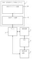
- FIG. 1 is a block diagram illustrating an overview of functions of a SCADA web HMI system according to an embodiment.
- FIG. 3 is a diagram for explaining an example of a device list according to an embodiment.
- FIG. 3 is a diagram for explaining the characteristics of drawing the tip of a long material part arranged on the HMI screen according to the embodiment. It is a figure for demonstrating the characteristic of the tail end drawing of the elongate material part arrange
- FIG. 3 is a diagram for explaining integration of intra-zone movement distances according to the embodiment.
- FIG. 2 is a block diagram showing an example of the hardware configuration of an HMI server device and an HMI client device according to an embodiment.
- FIG. 1 is a diagram for explaining the system configuration of SCADA.
- SCADA includes a human machine interface (HMI) 1, a programmable logic controller (PLC) 2 as a supervisory control system, a communication device 3 as a communication infrastructure, and an RIO 4 as subsystems.
- HMI human machine interface
- PLC programmable logic controller
- SCADA connects to the monitored device 5 via PLC2 or RIO4.
- the monitored device 5 is a sensor, an actuator, etc. that constitute a plant to be monitored and controlled.
- the HMI 1 (SCADA web HMI system) includes a SCADA web HMI server device (hereinafter referred to as HMI server device 10) and at least one SCADA web HMI client device (hereinafter referred to as HMI client device 20).
- the HMI server device 10 is connected to the PLC 2 and the HMI client device 20 via a computer network.
- the HMI server device 10 transmits update data (PLC signal) for updating the display state of the HMI screen 22 to the web browser 21 in response to the signal received from the PLC 2. Additionally, the HMI server device 10 receives a control signal from the web browser 21 and transmits it to the PLC 2.
- PLC signal update data
- the HMI client device 20 is a thin client that does not include monitoring control logic, and includes at least one monitor 20e (FIG. 10).
- the HMI client device 20 executes a web browser 21, and the web browser 21 is displayed in full screen on the monitor 20e.
- the web browser 21 communicates with the HMI server device 10 and draws an HMI screen 22 on which parts displaying the status of the plant are arranged.
- the HMI screen 22 illustrated in FIG. 2 will be explained.
- the HMI screen 22 displays the tracking status of the rolled material in the rough rolling section of the hot rolling line.
- the rough rolling mill shown in FIG. 2 is a tandem rolling mill in which three rolling stands (R1, R2, R3) are arranged in series.
- the rough rolling mill can roll the material to be rolled in the forward direction (from upstream to downstream) and the reverse direction (from downstream to upstream).
- the HMI screen 22 includes display parts showing the first rolling stand R1, the second rolling stand R2, the third rolling stand R3, and the conveyance table 6 that conveys the rolled material (long material).
- the HMI screen 22 includes long material parts (S0, S1, S2, S3) whose display length in the longitudinal direction can be expanded and contracted to indicate the inventory status of the rolled material.
- S0 is arranged upstream of the first rolling stand R1.
- S1 is arranged in a section (denoted as a first zone Z1) between the first rolling stand R1 and the second rolling stand R2.
- S2 is arranged in a section (denoted as second zone Z2) between the second rolling stand R2 and the third rolling stand R3.
- S3 is located downstream of the third rolling stand.
- the HMI server device 10 includes a processor 10a that executes various processes, and a memory 10b that stores various information (including programs).
- the various information includes screen data 13, parts library 14, and device list 15.
- the processor 10a functions as a PLC signal processing section 11 and a web server processing section 12 by reading various information stored in the memory 10b and executing programs.
- the PLC signal processing section 11 and the web server processing section 12 can mutually transmit and receive data through inter-process communication.
- the screen data 13 is vector data defined for each HMI screen 22.
- vector data is data in Scalable Vector Graphics (SVG) format.
- SVG data includes part names, shapes, positions, colors, and sizes of parts placed on the HMI screen 22 as attributes of SVG elements.
- the screen data 13 includes a screen name.
- the screen data 13 of the HMI screen 22 shown in FIG. include.
- the parts library 14 includes a set of scripts that describe operations for each type of parts placed on the HMI screen 22.
- the script is a JavaScript (registered trademark) program defined for each part type.
- the script can be executed on each web browser 21 with parameter values given as needed.
- the script for long material parts (S0, S1, S2, S3) includes the value of the inventory flag included in the PLC signal, the value of the tip inventory flag, the value of the tail inventory flag, the transport speed reference value, The drawing size (display length, display position) of the long material part is output using the reception time of the PLC signal as an input value.
- the inventory flag is ON when a part of the material to be rolled exists within the zone.
- the tip presence flag is ON when the tip of the material to be rolled exists within the zone.
- the tail end stock flag is ON when the tail end of the material to be rolled exists within the zone.
- the values of the stock flag, the tip stock flag, and the tail stock flag are calculated by the PLC 2 based on the sensor values of the rolling load sensor of the rolling stand and the sensor values of a laser sensor placed near the rolling stand.
- the conveyance speed reference value is the conveyance speed of the rolled material calculated by the PLC 2 based on the work roll rotation speed and work roll diameter of the rolling stand.
- the device list 15 is data defined for each HMI screen 22, and is, for example, data in Comma-Separated Values (CSV) format.
- the device list 15 is data that associates item names linked to parts arranged on the HMI screen 22 and communication addresses of PLCs. Item names and communication addresses are unique in the system.
- FIG. 3 is a diagram showing a part of the device list 15 related to the HMI screen 22 shown in FIG. 2.
- "G100” is a screen number.
- the part name of the first long material part S1, which displays the stock status in the first zone Z1 arranged in "G100”, is "G100_1SLAB”.
- Four tracking items are set in the first long material part S1.
- the item names are "G100_1SLAB_M”, “G100_1SLAB_HE”, “G100_1SLAB_TE”, and “G100_1SLAB_SRF", respectively.
- “G100_1SLAB_M” is an inventory flag for the first zone Z1, and the data type is Boolean.
- G100_1SLAB_HE is the leading stock flag of the first zone Z1, and the data type is Boolean.
- G100_1SLAB_TE is the tail end inventory flag of the first zone Z1, and the data type is Boolean.
- G100_1SLAB_SRF is the transport speed reference for the first zone Z1, and the data type is a real number type.
- the part name of the second long material part S2 that displays the stock status in the second zone Z2 located in "G100” is "G100_2SLAB".
- Four tracking items are set in the second long material part S2.
- the item names are "G100_2SLAB_M”, “G100_2SLAB_HE”, “G100_2SLAB_TE”, and "G100_2SLAB_SRF", respectively.
- “G100_2SLAB_M” is an inventory flag for the second zone Z2, and the data type is Boolean.
- “G100_2SLAB_HE” is the leading stock flag of the second zone Z2, and the data type is Boolean.
- G100_2SLAB_TE is the tail end inventory flag of the second zone Z2, and the data type is Boolean.
- G100_2SLAB_SRF is the transport speed reference for the second zone Z2, and the data type is a real number type.
- the PLC signal processing section 11 periodically receives a PLC signal from the PLC 2 based on the communication address included in the device list 15 and transmits it to the web server processing section 12 .
- the reception cycle of the PLC signal is a low cycle (approximately 200 to 1000 msec). Further, the PLC signal processing unit 11 transmits the control signal received from the web server processing unit 12 to the PLC 2.
- the web server processing unit 12 can communicate with the web browser 21 (web browser processing unit 31) of the HMI client device 20 using HTTP (Hypertext Transfer Protocol), HTTPS (Hypertext Transfer Protocol Secure), and WebSocket.
- the web server processing unit 12 generates content for each HMI screen based on screen data 13 (SVG file) for each HMI screen, a parts library 14 that describes operations for each part type, and a device list 15.
- the content includes an HTML file, screen data 13 (SVG file), and parts library 14.
- the web server processing unit 12 transmits content in response to a request from the web browser 21 (web browser processing unit 31).
- the web server processing section 12 receives the PLC signal from the PLC signal processing section 11. Based on the device list 15, the web server processing unit 12 sends the PLC signal (value of the item name corresponding to the PLC signal) to the web browser 21 displaying the HMI screen 22 having the item name corresponding to the received PLC signal. ) to send.
- the HMI client device 20 includes a processing circuit 30 (including a processor 20a that executes various processes and a memory 20b that stores various information (including programs) shown in FIG. 10, which will be described later), and a monitor 20e.
- the processor 20a functions as a web browser processing unit 31 by reading various information stored in the memory 20b and executing programs.
- the web browser processing unit 31 is executed for each web browser 21.
- the web browser 21 draws an HMI screen 22 for monitoring and controlling an industrial plant.
- a plurality of parts are arranged on the HMI screen 22.
- the parts include, for example, operation parts for transmitting control signals to the PLC 2 in response to operator operations, display parts whose display status (numbers, characters, colors, shapes) changes depending on received PLC signals, etc. .
- the web browser processing unit 31 receives the above-mentioned content (HTML file, screen data 13, parts library 14) from the web server processing unit 12, and stores it in the memory 20b. Based on the content, the web browser 21 draws an HMI screen 22 on which parts are arranged.
- HTML file HTML file, screen data 13, parts library 14
- the web browser processing unit 31 executes a script for each part type included in the above-mentioned parts library 14 according to the part type of the parts arranged on the HMI screen 22.
- scripts for long material parts S0, S1, S2, S3 will be described.
- the script for the long material part changes the drawing size of the long material part in accordance with input values based on the received PLC signal (the values of the four tracking items described above and the reception time of the PLC signal).
- FIG. 4 shows the state of the first long material part S1 after receiving the first PLC signal including the timing when the tip of the material to be rolled enters the first zone Z1 and the reference conveyance speed value of the material to be rolled.
- FIG. 3 is a diagram for explaining continuous drawing.
- the web browser processing unit 31 From the time when the first PLC signal is received, the web browser processing unit 31 performs the first Calculate the tip position H1 of the long material part.
- the web browser processing unit 31 sets the drawing size of the first elongated material part S1 to the length from the entrance side of the first zone Z1 to the first elongated material part tip position H1.
- the web browser processing unit 31 draws the range from the entry side of the first zone Z1 to the first long material part tip position H1 for the first long material part S1 in a lighting color, and The range from H1 to the exit side of the first zone Z1 is drawn in an unlit color.
- the PLC signal is received at a low cycle (200 to 1000 msec), and each time a drawing cycle arrives without waiting for the next PLC signal, the tip of the first long material part S1 is moved to the first zone. It is possible to advance toward the exit side of Z1, and the tracking status of the rolled material can be displayed smoothly.
- the second PLC signal includes the timing when the leading end of the rolled material enters the second zone Z2 after receiving the first PLC signal and the reference value of the conveyance speed of the rolled material.
- the first elongated material part tip position H1 does not reach the second zone Z2 when the first elongated material part tip position H1 is received.
- the tip position of the first long material part S1 drawn on the HMI screen 22 has not caught up with the tip position of the actual rolled material.
- the web browser processing unit 31 immediately sets the drawing size (display length) of the first long material part S1 to the zone length (100%) of the first zone ((C) in FIG. 4).
- the web browser processing unit 31 draws the range of the first long material part S1 from the entrance side of the first zone Z1 to the first long material part tip position H1 (the exit side of the first zone Z1) in a lighting color. .
- the tip position of the first long material part S1 drawn on the HMI screen 22 can be made to catch up with the tip position of the actual rolled material.
- the web browser processing unit 31 updates the transport speed reference value included in the second PLC signal and the second PLC signal for each drawing cycle from the time when the second PLC signal is received.
- the second elongated material part tip position H2 is calculated based on the elapsed time since receiving the elapsed time.
- the web browser processing unit 31 sets the drawing size of the second long material part S2 to the length from the entrance side of the second zone Z2 to the second long material part tip position H2.
- the web browser processing unit 31 draws the range from the entrance side of the second zone Z2 to the second long material part tip position H2 in a lighting color for the second long material part S2, and draws the range from the entrance side of the second zone Z2 to the second long material part tip position H2, and The range from the position H2 to the exit side of the second zone Z2 is drawn in an unlit color.
- the PLC signal is received at low cycles, and each time a drawing cycle arrives without waiting for the next PLC signal, the tip of the second long material part S2 is moved to the exit side of the second zone Z2.
- the tracking status of the rolled material can be displayed smoothly.
- FIG. 5 shows the first long material part S1 after receiving the third PLC signal including the timing when the tail end of the material to be rolled enters the first zone Z1 and the reference conveyance speed value of the material to be rolled.
- FIG. 3 is a diagram for explaining continuous drawing.
- the web browser processing unit 31 performs the first Calculate the tail end position T1 of the long material part.
- the web browser processing unit 31 sets the drawing size of the first elongated material part S1 to the length from the first elongated material part tail end position T1 to the exit side of the first zone Z1.
- the web browser processing unit 31 draws the range from the entrance side of the first zone Z1 to the tail end position T1 of the first long material part S1 in an unlit color, and The range from the tail end position T1 to the exit side of the first zone Z1 is drawn in a lighting color.
- the PLC signal is received at low cycles, and each time a drawing cycle arrives without waiting for the next PLC signal, the tail end of the first long material part S1 is moved to the exit side of the first zone Z1.
- the tracking status of the rolled material can be displayed smoothly.
- the fourth PLC includes the timing when the tail end of the rolled material enters the second zone Z2 after receiving the third PLC signal and the reference value of the conveyance speed of the rolled material.
- the first elongated material part tail end position T1 may not have reached the second zone Z2. In this case, the tail end position of the first long material part S1 drawn on the HMI screen 22 has not caught up with the tail end position of the actual rolled material.
- the web browser processing unit 31 immediately sets the drawing size (display length) of the first long material part S1 to length 0 ((C) in FIG. 5).
- the web browser processing unit 31 draws the range from the entrance side to the exit side of the first zone Z1 in the unlit color for the first elongated material part S1.
- the tail end position of the first long material part S1 drawn on the HMI screen 22 can be made to catch up with the tail end position of the actual rolled material.
- the web browser processing unit 31 updates the transport speed reference value included in the fourth PLC signal and the fourth PLC signal for each drawing cycle from the time when the fourth PLC signal is received.
- the tail end position T2 of the second elongated material part is calculated based on the elapsed time since receiving the elapsed time.
- the web browser processing unit 31 sets the drawing size of the second elongated material part S2 to the length from the second elongated material part tail end position T2 to the exit side of the second zone Z2.
- the web browser processing unit 31 draws the range from the entry side of the second zone Z2 to the tail end position T2 of the second long material part S2 in an unlit color, and draws the range from the entrance side of the second zone Z2 to the second long material part tail end position T2, and The range from the tail end position T2 to the exit side of the second zone Z2 is drawn in a lighting color.
- the PLC signal is received at low cycles, and each time a drawing cycle arrives without waiting for the PLC signal, the tail end of the second long material part S2 is directed toward the exit side of the second zone Z2.
- the tracking display of the rolled material can be expressed smoothly.
- the first PLC signal (or third PLC signal) including the timing when the leading end (or tail end) of the material to be rolled enters the first zone Z1 is received.
- the PLC signal that can be received until the second PLC signal is received, which includes the timing at which the leading end (or tail end) of the rolled material enters the second zone Z2 (exits the first zone Z1).
- a plurality of PLC signals (referred to as intermediate PLC signals) may be received between when the first PLC signal is received and when the second PLC signal is received.
- the intermediate PLC signal is a PLC signal that has a different transport speed reference value from the first PLC signal (or third PLC signal).
- the web browser processing unit 31 integrates the moving distance within the zone of the tip (or tail end) of the rolled material, taking into account the latest conveyance speed reference value included in the intermediate PLC signal, and Calculate the position of the tip (or tail) of a timber part.
- the web browser processing unit 31 receives the first intermediate PLC signal including the transport speed reference value between receiving the first PLC signal and receiving the second PLC signal.
- the distance based on the conveyance speed reference value included in the first intermediate PLC signal and the elapsed time after receiving the first intermediate PLC signal is calculated as the first elongated distance when the first intermediate PLC signal is received.
- the first elongated material part tip position H1 is updated.
- the web browser processing unit 31 sets the drawing size of the first elongated material part S1 to the length from the entrance side of the first zone Z1 to the first elongated material part tip position H1.
- the web browser processing unit 31 when the web browser processing unit 31 receives the third intermediate PLC signal including the transport speed reference value between receiving the third PLC signal and receiving the fourth PLC signal, the web browser processing unit 31 outputs the third intermediate PLC signal. Add the distance based on the transport speed reference value included in the reference value and the elapsed time since receiving the third intermediate PLC signal to the tail end position T1 of the first long material part when the third intermediate PLC signal is received. As a result, the tail end position T1 of the first long material part is updated. The web browser processing unit 31 sets the drawing size of the first elongated material part S1 to the length from the first elongated material part tail end position T1 to the exit side of the first zone Z1.
- FIG. 6 is a diagram for explaining the integration of the intra-zone movement distance in the micro-tracking zone.
- n is the number of speed changes
- t(n) is time
- t(0) is the tip (tail) inventory ON time [sec]
- t(N+1) is the tip (tail) inventory OFF time [sec].
- sec] v(n) is the transport speed reference value [m/sec].
- the PLC signal is received n times before the leading end (tail end) passes through the first zone Z1.
- the transport speed reference value can be changed in each PLC signal.
- the intra-zone movement distance P(N) [m] is expressed by the following equation (1).
- FIG. 7 is a diagram showing the tip position and tail end position of the elongated material part based on the intra-zone movement distance P(N).
- FIG. 7A is a diagram showing the tip movement distance P HEAD (t) of the long material part calculated using equation (1).
- FIG. 7B is a diagram showing the tail end movement distance P TAIL (t) of the long material part calculated using equation (1).
- (C) of FIG. 7 is a diagram showing the tip movement distance P HEAD (t) and the tail end movement distance P TAIL (t) of the long material part calculated using equation (1).
- the ratio of the display length to the maximum length (zone length L [m]) of the elongated material part in (C) of FIG. 7 is expressed by the following equation (2).
- the drawing process for long material parts according to this embodiment will be described with reference to the flowcharts shown in FIGS. 8 and 9.
- the process shown in the flowchart is executed for each long material part in each zone every drawing cycle.
- the drawing cycle is usually sufficiently shorter than the PLC reception cycle, but the drawing cycle is not constant because it changes depending on the load status of the browser.
- step S100 the web browser processing unit 31 determines whether the inventory flag included in the latest received PLC signal is ON or OFF.
- the inventory flag is ON when a part of the material to be rolled exists within the zone. If the inventory flag is ON, the process of step S110 is executed. If the inventory flag is OFF, the process of step S310 is executed.
- the inventory flag is "G100_1SLAB_M" in the first zone Z1 and "G100_2SLAB_M" in the second zone Z2 (FIG. 3).
- step S110 the web browser processing unit 31 determines whether the tip inventory flag included in the latest PLC signal is ON or OFF.
- the tip stock flag is ON when the tip of the material to be rolled exists within the zone. If the leading end inventory flag is ON, the process of step S120 is executed. If the tip inventory flag is OFF, the tip position is set to 100% in step S125, and then the process of step S160 is executed.
- step S120 the web browser processing unit 31 determines whether the tip inventory flag is switched from OFF to ON by the latest PLC signal, and the conveyance speed reference value included in the PLC signal is a negative value. .
- the conveyance speed reference value is a negative value, reverse rolling is being performed, and the material to be rolled is being rolled from the downstream side to the upstream side of the rolling line. If the determination condition of step S120 is satisfied, the process of step S130 is executed. If the determination condition is not satisfied, the tip start position is set to 0% in step S135, and then the process of step S140 is executed.
- step S120 If the judgment condition in step S120 is satisfied, that is, if the tip of the material to be rolled enters the zone from the downstream side of the rolling line during reverse rolling, in step S130, the starting position of the tip of the zone is the maximum of the long material part.
- the length (zone length) is set to 100%. After that, the process of step S140 is executed.
- step S140 the web browser processing unit 31 integrates the conveyance speed reference value x time based on each PLC signal received since the tip inventory flag was switched to ON, and moves the tip of the long material part. Calculate the distance (Equation (1)).
- step S150 the web browser processing unit 31 calculates the tip position of the long material part from the tip start position and the tip movement distance.
- the first elongated material part tip position H1 in the first zone Z1 shown in FIG. 4 is calculated.
- step S160 the web browser processing unit 31 draws only the area from the tail end position to the leading end position of the long material part on the HMI screen 22 in a lighting color ((C) in FIG. 7). For example, in a zone where the tip of the material to be rolled is stocked, the area from the entry side of the zone to the tip of the long material part is drawn in a lit color ((A) in FIG. 7). In the zone where the tail end of the material to be rolled is stocked, the area from the tail end position of the long material part to the exit side of the zone is drawn in a lit color ((B) in FIG. 7).
- the area from the entry side to the exit side of the zone is displayed in a lit color.
- the area from the entry side to the exit side of the zone is displayed in an unlit color.
- step S310 the web browser processing unit 31 resets the leading end position and tail end position of the long material part in the zone where the inventory flag is OFF to 0%. Thereafter, the process of step S160 described above is executed.
- step S100 the process of step S210 shown in FIG. 9 is executed.
- step S210 the web browser processing unit 31 determines whether the tail end inventory flag included in the latest PLC signal is ON or OFF.
- the tail end inventory flag is ON when the tail end of the material to be rolled exists within the zone. If the tail end inventory flag is ON, the process of step S220 is executed. If the tail end inventory flag is OFF, the tail end position is set to 100% in step S225, and then the routine returns to FIG. 8.
- step S220 the web browser processing unit 31 determines whether the tail end inventory flag included in the latest PLC signal has been switched from OFF to ON, and whether the conveyance speed reference value included in the PLC signal is a negative value. Determine. When the conveyance speed reference value is a negative value, reverse rolling is being performed, and the material to be rolled is being rolled from the downstream side to the upstream side of the rolling line. If the determination condition of step S220 is satisfied, the process of step S230 is executed. If the determination condition is not satisfied, the tail end start position is set to 0% in step S235, and then the process of step S240 is executed.
- step S230 If the determination condition in step S220 is satisfied, that is, if the tail end of the rolled material enters the zone from the downstream side of the rolling line during reverse rolling, in step S230, the starting position of the tail end of the zone is the part of the long material. is set to 100% of the maximum length (zone length). After that, the process of step S240 is executed.
- step S240 the web browser processing unit 31 integrates the conveyance speed reference value x time based on each PLC signal received from the time when the tail end inventory flag was turned ON until now, and calculates the tail end of the long material part.
- the end movement distance is calculated (Equation (1)).
- step S250 the web browser processing unit 31 calculates the tail end position of the long material part from the tail end start position and the tail end movement distance.
- the first long material part tail end position T1 in the first zone Z1 shown in FIG. 5 is calculated. Thereafter, the process returns to the routine of FIG.
- the tip (and tail) position of the rolled material is estimated and the position of the tip (and tail end) of the rolled material is Change the drawing size of parts.
- the tip (and tail) position of the material to be rolled can be accurately tracked on the HMI screen without waiting for the PLC signal reception period. Furthermore, when the latest PLC signal is received, the tracking display on the HMI screen can be corrected.
- rolled materials such as slabs and strips are exemplified as specific examples of long material parts, but the shapes may be rod-like, linear, sheet-like, etc.
- the material may be resin, paper, or the like.
- the zone is not limited to between rolling stands of a rough rolling mill, but may be between rolling stands of a finishing rolling mill, between rolls of a looper, or the like. Moreover, it is not limited to a rolling line.
- the SCADA web HMI system is divided into the HMI server device 10 and the HMI client device 20, but the system configuration is not limited to this.
- it may be configured with a single device that functions as both a server function and a client function.
- the HMI screen 22 is drawn on the web browser 21, but the HMI screen 22 may be drawn on the monitor 20e without going through the web browser 21.
- the parts displayed on the HMI screen 22 are drawn in 2D, but they may be drawn in 3D.
- a 3D-shaped block is displayed in the area of the lit color, instead of being filled with the lit color and unlit color as described here.
- FIG. 10 is a block diagram showing a hardware configuration example of the HMI server device 10 and the HMI client device 20.
- Each process of the HMI server device 10 described above is realized by a processing circuit.
- the processing circuit is configured by connecting a processor 10a, a memory 10b, and a network interface 10c.
- the processor 10a implements each function of the HMI server device 10 by executing various programs stored in the memory 10b.
- Memory 10b includes a main storage device and an auxiliary storage device.
- the memory 10b stores the above-described screen data 13, parts library 14, and device list 15 in advance.
- the network interface 10c is a device that connects to the PLC 2 and the HMI client device 20 via a computer network and is capable of transmitting and receiving PLC signals and control signals.
- Each process of the HMI client device 20 described above is realized by a processing circuit.
- the processing circuit is configured by connecting a processor 20a, a memory 20b, a network interface 20c, an input interface 20d, and at least one monitor 20e.
- the processor 20a implements each function of the HMI client device 20 by executing various programs stored in the memory 20b.
- Memory 10b includes a main storage device and an auxiliary storage device.
- the network interface 20c is a device that is connected to the HMI server device 10 via a computer network and is capable of transmitting and receiving PLC signals and control signals.
- the input interface 20d is an input device such as a keyboard, mouse, or touch panel.
- a plurality of monitors 20e may be provided.
- the HMI client device 20 may be a mobile terminal such as a tablet.
Abstract
SCADAウェブHMIシステムは、第1ゾーンに配置される第1長尺材パーツと第2ゾーンに配置される伸縮可能な第2長尺材パーツとを含むHMI画面を描画する。第1長尺材パーツおよび第2長尺材パーツはPLC信号の受信周期よりも短い描画周期毎に描画される。第1長尺材パーツ先端位置は、第1PLC信号を受信した時から描画周期毎に、第1PLC信号に含まれた搬送速度と経過時間とに基づいて計算される。第1長尺材パーツの描画サイズは、第1ゾーンの入側から第1長尺材パーツ先端位置までの長さに設定される。また、第1長尺材パーツの描画サイズは、第2PLC信号を受信した時に、第1長尺材パーツ先端位置が第2ゾーンに達していない場合に、前記第1ゾーンのゾーン長に設定される。
Description
本開示は、SCADAウェブHMIシステムに関する。
SCADA(Supervisory Control And Data Acquisition)は、社会インフラシステムを監視制御する仕組みとして知られている。社会インフラシステムは、鉄鋼圧延システム、電力送変電システム、上下水道処理システム、ビル管理システム、道路システムなどである。
SCADAは、産業制御システムの一種であり、コンピュータによるシステム監視とプロセス制御を行う。SCADAでは、システムの処理性能に合わせた即応性(リアルタイム性)が必要である。
SCADAは一般に次のようなサブシステムから構成される。
(1)HMI(Human Machine Interface)
HMIは、対象プロセス(監視対象装置)のデータをオペレータに提示し、オペレータがプロセスを監視し制御できるようにする機構である。例えば特許文献1には、SCADAクライアント上で動作するHMI画面(HMI Screen)を備えるSCADA HMIが開示されている。
(2)監視制御システム
監視制御システムは、プロセス上の信号データ(PLC信号)を収集し、プロセスに対して制御コマンド(制御信号)を送る。監視制御システムは、PLC(Programmable Logic Controller)などによって構成される。
(3)遠方入出力装置(Remote Input Output)
遠方入出力装置は、プロセス内に設置されたセンサと接続し、センサの信号をデジタルのデータに変換し、そのデジタルデータを監視制御システムに送る。
(4)通信基盤
通信基盤は、監視制御システムと遠方入出力装置を接続する。
上述した鉄鋼圧延システムの1つに熱間圧延ラインがある。熱間圧延ラインは、被圧延材を圧延する複数の圧延スタンドを有する圧延機(粗圧延機、仕上圧延機)を備える。従来のSCADA HMIでは、HMI画面に各圧延スタンドを表示し、PLCからPLC信号を受信した時に、各圧延スタンド間(ゾーン)に被圧延材が在荷しているか否かを2値(ONかOFFか)で表示していた。
しかしながら、実際の被圧延材は熱間圧延ラインの上流側から下流側へ時間経過とともに搬送される。そのため、ゾーン内を移動する実際の被圧延材の先端位置や尾端位置を、トラッキングしHMI画面に表示することが望まれている。
特に、PLCからの信号が低周期(200~1000msec)である場合は、PLC信号の受信周期を待たずに、被圧延材の先端位置や尾端位置を推定してHMI画面にトラッキング状況を表示できることが望まれる。
特に、PLCからの信号が低周期(200~1000msec)である場合は、PLC信号の受信周期を待たずに、被圧延材の先端位置や尾端位置を推定してHMI画面にトラッキング状況を表示できることが望まれる。
本開示は、上述のような課題を解決するためになされたもので、PLC信号の受信周期を待たずにHMI画面上で被圧延材の先端(および尾端)位置を精度高くトラッキングでき、最新のPLC信号を受信した場合にHMI画面上のトラッキング表示を補正できるSCADAウェブHMIシステムを提供することを目的とする。
第1の観点は、SCADAウェブHMIシステムに関連する。
前記SCADAウェブHMIシステムは、PLCから受信周期毎にPLC信号を受信する。
前記SCADAウェブHMIシステムは、少なくとも1つのプロセッサとモニタとを備える。
前記プロセッサは以下のように構成されている。
前記プロセッサは、長尺材を搬送する搬送テーブルの第1ゾーンに配置される伸縮可能な第1長尺材パーツと、前記第1ゾーンに隣接する第2ゾーンに配置される伸縮可能な第2長尺材パーツと、を含むHMI画面を前記モニタに描画する。ここで、前記第1長尺材パーツおよび前記第2長尺材パーツは前記受信周期よりも短い描画周期毎に描画される。
前記プロセッサは、前記長尺材の先端が前記第1ゾーンに入ったタイミングと前記長尺材の搬送速度とを含む第1PLC信号を受信した時から、前記描画周期毎に、前記第1PLC信号に含まれた前記搬送速度と前記第1PLC信号を受信してからの経過時間とに基づいて第1長尺材パーツ先端位置を計算する。
前記プロセッサは、前記第1長尺材パーツの描画サイズを前記第1ゾーンの入側から前記第1長尺材パーツ先端位置までの長さに設定する。
前記プロセッサは、前記第1PLC信号を受信した後に前記長尺材の前記先端が前記第2ゾーンに入ったタイミングと前記長尺材の搬送速度とを含む第2PLC信号を受信した時に、前記第1長尺材パーツ先端位置が前記第2ゾーンに達していない場合に、前記第1長尺材パーツの描画サイズを前記第1ゾーンのゾーン長に設定する。
前記プロセッサは、前記第2PLC信号を受信した時から、前記描画周期毎に、前記第2PLC信号に含まれた前記搬送速度と前記第2PLC信号を受信してからの経過時間とに基づいて第2長尺材パーツ先端位置を計算する。
前記プロセッサは、前記第2長尺材パーツの描画サイズを前記第2ゾーンの入側から前記第2長尺材パーツ先端位置までの長さに設定する。
第2の観点は、第1の観点に加えて、次の特徴を更に有する。
前記プロセッサは、前記第1PLC信号を受信してから前記第2PLC信号を受信するまでの間に搬送速度を含む第1中間PLC信号を受信した場合に、前記第1中間PLC信号に含まれた前記搬送速度と前記第1中間PLC信号を受信してからの経過時間とに基づく距離を、前記第1中間PLC信号を受信した時の前記第1長尺材パーツ先端位置に加えることで前記第1長尺材パーツ先端位置を更新する。
前記プロセッサは、前記第1長尺材パーツの描画サイズを前記第1ゾーンの入側から前記第1長尺材パーツ先端位置までの長さに設定する。
前記プロセッサは、前記第1PLC信号を受信してから前記第2PLC信号を受信するまでの間に搬送速度を含む第1中間PLC信号を受信した場合に、前記第1中間PLC信号に含まれた前記搬送速度と前記第1中間PLC信号を受信してからの経過時間とに基づく距離を、前記第1中間PLC信号を受信した時の前記第1長尺材パーツ先端位置に加えることで前記第1長尺材パーツ先端位置を更新する。
前記プロセッサは、前記第1長尺材パーツの描画サイズを前記第1ゾーンの入側から前記第1長尺材パーツ先端位置までの長さに設定する。
第3の観点は、第1又は2の観点に加えて、次の特徴を更に有する。
前記プロセッサは、前記長尺材の尾端が前記第1ゾーンに入ったタイミングと前記長尺材の搬送速度とを含む第3PLC信号を受信した時から、前記描画周期毎に、前記第3PLC信号に含まれた搬送速度と前記第3PLC信号を受信してからの経過時間とに基づいて第1長尺材パーツ尾端位置を計算する。
前記プロセッサは、前記第1長尺材パーツの描画サイズを前記第1長尺材パーツ尾端位置から前記第1ゾーンの出側までの長さに設定する。
前記プロセッサは、前記第3PLC信号を受信した後に前記長尺材の前記尾端が前記第2ゾーンに入ったタイミングと前記長尺材の搬送速度とを含む第4PLC信号を受信した時に、前記第1長尺材パーツ尾端位置が前記第2ゾーンに達していない場合に、前記第1長尺材パーツの描画サイズを長さ0に設定する。
前記プロセッサは、前記第4PLC信号を受信した時から、前記描画周期毎に、前記第4PLC信号に含まれた前記搬送速度と前記第4PLC信号を受信してからの経過時間とに基づいて第2長尺材パーツ尾端位置を計算する。
前記プロセッサは、前記第2長尺材パーツの描画サイズを前記第2長尺材パーツ尾端位置から前記第2ゾーンの出側までの長さに設定する。
第4の観点は、第3の観点に加えて、次の特徴を更に有する。
前記プロセッサは、前記第3PLC信号を受信してから前記第4PLC信号を受信するまでの間に搬送速度を含む第3中間PLC信号を受信した場合に、前記第3中間PLC信号に含まれた前記搬送速度と前記第3中間PLC信号を受信してからの経過時間とに基づく距離を、前記第3中間PLC信号を受信した時の前記第1長尺材パーツ尾端位置に加えることで前記第1長尺材パーツ尾端位置を更新する。
前記プロセッサは、前記第1長尺材パーツの描画サイズを前記第1長尺材パーツ尾端位置から前記第1ゾーンの出側までの長さに設定する。
前記プロセッサは、前記第3PLC信号を受信してから前記第4PLC信号を受信するまでの間に搬送速度を含む第3中間PLC信号を受信した場合に、前記第3中間PLC信号に含まれた前記搬送速度と前記第3中間PLC信号を受信してからの経過時間とに基づく距離を、前記第3中間PLC信号を受信した時の前記第1長尺材パーツ尾端位置に加えることで前記第1長尺材パーツ尾端位置を更新する。
前記プロセッサは、前記第1長尺材パーツの描画サイズを前記第1長尺材パーツ尾端位置から前記第1ゾーンの出側までの長さに設定する。
第5の観点は、第1乃至第4の観点のいずれかに加えて、次の特徴を更に有する。
前記長尺材はタンデム圧延機で圧延される被圧延材である。
前記第1ゾーンおよび前記第2ゾーンはそれぞれ前記タンデム圧延機の圧延スタンド間である。
前記長尺材はタンデム圧延機で圧延される被圧延材である。
前記第1ゾーンおよび前記第2ゾーンはそれぞれ前記タンデム圧延機の圧延スタンド間である。
第6の観点は、第1乃至第5の観点のいずれかに加えて、次の特徴を更に有する。
前記プロセッサは、ウェブブラウザを実行するように構成されている。
前記ウェブブラウザは、前記描画周期毎に前記HMI画面を描画する。
前記プロセッサは、ウェブブラウザを実行するように構成されている。
前記ウェブブラウザは、前記描画周期毎に前記HMI画面を描画する。
本開示によれば、PLC信号の受信周期を待たずにHMI画面上で被圧延材の先端(および尾端)位置を精度高くトラッキングでき、最新のPLC信号を受信した場合にHMI画面上のトラッキング表示を補正できる。
以下、図面を参照して本発明の実施の形態について詳細に説明する。尚、各図において共通する要素には、同一の符号を付して重複する説明を省略する。
実施の形態.
1.全体システム
1.全体システム
図1は、SCADAのシステム構成を説明するための図である。SCADAは、ヒューマンマシンインターフェース(HMI)1、監視制御システムとしてのプログラマブルロジックコントローラ(PLC)2、通信基盤としての通信装置3、RIO4をサブシステムとして備える。SCADAは、PLC2またはRIO4を介して監視対象装置5に接続する。
PLC2(監視制御システム)、通信装置3(通信基盤)、RIO4に関する説明は、背景技術で述べた通りであるため省略する。監視対象装置5は、監視制御対象のプラントを構成するセンサ、アクチュエータなどである。
HMI1(SCADAウェブHMIシステム)は、SCADAウェブHMIサーバ装置(以下、HMIサーバ装置10と記す)と、少なくとも一つのSCADAウェブHMIクライアント装置(以下、HMIクライアント装置20と記す)とを備える。
2.SCADAウェブHMIシステム
図2を参照して、SCADAウェブHMIシステムについて説明する。
図2を参照して、SCADAウェブHMIシステムについて説明する。
HMIサーバ装置10は、コンピュータネットワークを介してPLC2とHMIクライアント装置20に接続する。HMIサーバ装置10は、PLC2から受信した信号に応じてHMI画面22の表示状態を更新するための更新データ(PLC信号)をウェブブラウザ21へ送信する。また、HMIサーバ装置10は、ウェブブラウザ21から制御信号を受信してPLC2へ送信する。
HMIクライアント装置20は、監視制御ロジックを含まないシンクライアントであり、少なくとも1つのモニタ20e(図10)を備える。HMIクライアント装置20は、ウェブブラウザ21を実行し、ウェブブラウザ21はモニタ20eにフルスクリーンで表示される。ウェブブラウザ21は、HMIサーバ装置10と通信し、プラントの状態を表示するパーツが配置されたHMI画面22を描画する。
図2に例示されているHMI画面22について説明する。HMI画面22には、熱間圧延ラインの粗圧延セクションおける被圧延材のトラッキング状況が表示されている。図2に示す粗圧延機は、3台の圧延スタンド(R1,R2,R3)が直列に配置されたタンデム圧延機である。粗圧延機は、被圧延材を順方向(上流から下流へ)および逆方向(下流から上流へ)に圧延可能である。
HMI画面22は、第1圧延スタンドR1、第2圧延スタンドR2、第3圧延スタンドR3、および被圧延材(長尺材)を搬送する搬送テーブル6を示す表示パーツを含む。加えて、HMI画面22は、被圧延材の在荷状態を示すための、長手方向の表示長を伸縮自在な長尺材パーツ(S0,S1,S2,S3)を含む。S0は、第1圧延スタンドR1の上流に配置される。S1は、第1圧延スタンドR1と第2圧延スタンドR2との間の区間(第1ゾーンZ1と記す)に配置される。S2は、第2圧延スタンドR2と第3圧延スタンドR3との間の区間(第2ゾーンZ2と記す)に配置される。S3は、第3圧延スタンドの下流に配置される。
なお、粗圧延セクションや仕上圧延セクションのように長い区間はマクロトラッキングゾーンと呼ばれるのに対して、圧延スタンド間のように短い区間(Z1,Z2)はミクロトラッキングゾーンと呼ばれる。
2-1.SCADAウェブHMIサーバ装置の構成
より詳細にHMIサーバ装置10について説明する。
HMIサーバ装置10は、後述する図10に示すように、各種処理を実行するプロセッサ10a、各種情報(プログラムを含む)が格納されるメモリ10bを備える。各種情報は、画面データ13、パーツライブラリ14、デバイスリスト15を含む。プロセッサ10aは、メモリ10bに記憶された各種情報を読み込み、プログラムを実行することにより、PLC信号処理部11、ウェブサーバ処理部12として機能する。PLC信号処理部11およびウェブサーバ処理部12はプロセス間通信により相互にデータを送受信可能である。
より詳細にHMIサーバ装置10について説明する。
HMIサーバ装置10は、後述する図10に示すように、各種処理を実行するプロセッサ10a、各種情報(プログラムを含む)が格納されるメモリ10bを備える。各種情報は、画面データ13、パーツライブラリ14、デバイスリスト15を含む。プロセッサ10aは、メモリ10bに記憶された各種情報を読み込み、プログラムを実行することにより、PLC信号処理部11、ウェブサーバ処理部12として機能する。PLC信号処理部11およびウェブサーバ処理部12はプロセス間通信により相互にデータを送受信可能である。
画面データ13は、HMI画面22毎に定義されたベクターデータである。例えば、ベクターデータは、Scalable Vector Graphics(SVG)フォーマットのデータである。SVGデータは、SVGエレメントの属性として、HMI画面22に配置されたパーツのパーツ名、形、位置、色、大きさを含む。なお、画面データ13には画面名が含まれる。
例えば、図2に示されているHMI画面22の画面データ13は、圧延スタンド(R1,R2,R3)のパーツ、搬送テーブル6のパーツ、長尺材パーツ(S0,S1,S2,S3)を含む。
例えば、図2に示されているHMI画面22の画面データ13は、圧延スタンド(R1,R2,R3)のパーツ、搬送テーブル6のパーツ、長尺材パーツ(S0,S1,S2,S3)を含む。
パーツライブラリ14は、HMI画面22に配置されるパーツの種別毎に動作を記述したスクリプトの集合を含む。スクリプトは、パーツ種別毎に定義されたJavaScript(登録商標)プログラムである。スクリプトは、必要に応じてパラメータ値が与えられて各ウェブブラウザ21上で実行可能である。例えば、長尺材パーツ(S0,S1,S2,S3)のスクリプトは、PLC信号に含まれる在荷フラグの値、先端在荷フラグの値、尾端在荷フラグの値、搬送速度基準値、およびPLC信号の受信時刻を入力値として、長尺材パーツの描画サイズ(表示長、表示位置)を出力する。
在荷フラグは、ゾーン内に被圧延材の一部が存在している場合にONである。先端在荷フラグは、ゾーン内に被圧延材の先端が存在している場合にONである。尾端在荷フラグは、ゾーン内に被圧延材の尾端が存在している場合にONである。在荷フラグと先端在荷フラグと尾端在荷フラグの値は、圧延スタンドの圧延荷重センサのセンサ値や圧延スタンドの近傍に配置されたレーザーセンサのセンサ値に基づいてPLC2により演算される。搬送速度基準値は、圧延スタンドのワークロール回転速度とワークロール径に基づいてPLC2により演算される被圧延材の搬送速度である。
デバイスリスト15は、HMI画面22毎に定義されたデータであり、例えばComma-Separated Values(CSV)フォーマットのデータである。デバイスリスト15は、HMI画面22に配置されたパーツに紐付けられたアイテム名と、PLCの通信アドレスとを関連付けたデータである。アイテム名および通信アドレスはシステムでユニークである。
図3は、図2に示されているHMI画面22に関するデバイスリスト15の一部を示す図である。「G100」は、スクリーン番号である。「G100」に配置された第1ゾーンZ1における在荷状態を表示する第1長尺材パーツS1のパーツ名は「G100_1SLAB」である。第1長尺材パーツS1には、4つのトラッキングアイテムが設定されている。アイテム名はそれぞれ、「G100_1SLAB_M」、「G100_1SLAB_HE」、「G100_1SLAB_TE」および「G100_1SLAB_SRF」である。「G100_1SLAB_M」は、第1ゾーンZ1の在荷フラグであり、データ型はブール型である。「G100_1SLAB_HE」は、第1ゾーンZ1の先端在荷フラグであり、データ型はブール型である。「G100_1SLAB_TE」は、第1ゾーンZ1の尾端在荷フラグであり、データ型はブール型である。「G100_1SLAB_SRF」は、第1ゾーンZ1の搬送速度基準であり、データ型は実数型である。
また、「G100」に配置された第2ゾーンZ2における在荷状態を表示する第2長尺材パーツS2のパーツ名は「G100_2SLAB」である。第2長尺材パーツS2には、4つのトラッキングアイテムが設定されている。アイテム名はそれぞれ、「G100_2SLAB_M」、「G100_2SLAB_HE」、「G100_2SLAB_TE」および「G100_2SLAB_SRF」である。「G100_2SLAB_M」は、第2ゾーンZ2の在荷フラグであり、データ型はブール型である。「G100_2SLAB_HE」は、第2ゾーンZ2の先端在荷フラグであり、データ型はブール型である。「G100_2SLAB_TE」は、第2ゾーンZ2の尾端在荷フラグであり、データ型はブール型である。「G100_2SLAB_SRF」は、第2ゾーンZ2の搬送速度基準であり、データ型は実数型である。
図2に戻り説明を続ける。
PLC信号処理部11は、デバイスリスト15に含まれる通信アドレスに基づいて周期的にPLC2からPLC信号を受信し、ウェブサーバ処理部12へ送信する。PLC信号の受信周期は低周期(約200~1000msec)である。また、PLC信号処理部11は、ウェブサーバ処理部12から受信した制御信号をPLC2へ送信する。
PLC信号処理部11は、デバイスリスト15に含まれる通信アドレスに基づいて周期的にPLC2からPLC信号を受信し、ウェブサーバ処理部12へ送信する。PLC信号の受信周期は低周期(約200~1000msec)である。また、PLC信号処理部11は、ウェブサーバ処理部12から受信した制御信号をPLC2へ送信する。
ウェブサーバ処理部12は、HMIクライアント装置20のウェブブラウザ21(ウェブブラウザ処理部31)と、HTTP(Hypertext Transfer Protocol)、HTTPS(Hypertext Transfer Protocol Secure)、WebSocketを用いて通信可能である。ウェブサーバ処理部12は、HMI画面毎の画面データ13(SVGファイル)、パーツ種別毎の動作を記述したパーツライブラリ14、デバイスリスト15に基づいて、HMI画面毎のコンテンツを生成する。コンテンツは、HTMLファイル、画面データ13(SVGファイル)、パーツライブラリ14を含む。ウェブサーバ処理部12は、ウェブブラウザ21(ウェブブラウザ処理部31)からのリクエストに応じてコンテンツを送信する。ウェブサーバ処理部12は、PLC信号処理部11からPLC信号を受信する。ウェブサーバ処理部12は、デバイスリスト15に基づいて、受信したPLC信号に対応するアイテム名を有するHMI画面22を表示しているウェブブラウザ21へ、PLC信号(PLC信号に応じたアイテム名の値)を送信する。
2-2.SCADAウェブHMIクライアント装置の構成
より詳細にHMIクライアント装置20について説明する。
HMIクライアント装置20は、処理回路30(後述する図10に示す、各種処理を実行するプロセッサ20a、各種情報(プログラムを含む)が格納されるメモリ20bを含む)、モニタ20eを備える。プロセッサ20aは、メモリ20bに記憶された各種情報を読み込み、プログラムを実行することにより、ウェブブラウザ処理部31として機能する。
より詳細にHMIクライアント装置20について説明する。
HMIクライアント装置20は、処理回路30(後述する図10に示す、各種処理を実行するプロセッサ20a、各種情報(プログラムを含む)が格納されるメモリ20bを含む)、モニタ20eを備える。プロセッサ20aは、メモリ20bに記憶された各種情報を読み込み、プログラムを実行することにより、ウェブブラウザ処理部31として機能する。
ウェブブラウザ処理部31は、ウェブブラウザ21ごとに実行される。ウェブブラウザ21は、産業プラントを監視制御するためのHMI画面22を描画する。HMI画面22には複数のパーツが配置されている。パーツは、例えば、オペレータの操作に応じてPLC2へ制御信号を送信するための操作パーツ、受信したPLC信号に応じて表示状態(数値、文字、色、形)が変化する表示パーツ、などを含む。
ウェブブラウザ処理部31は起動時に、ウェブサーバ処理部12から、上述したコンテンツ(HTMLファイル、画面データ13、パーツライブラリ14)を受信し、メモリ20bに記憶する。コンテンツに基づいて、ウェブブラウザ21は、パーツが配置されたHMI画面22を描画する。
ウェブブラウザ処理部31は、HMI画面22に配置されたパーツのパーツ種別に応じて、上述したパーツライブラリ14に含まれるパーツ種別毎のスクリプトを実行する。本実施形態では、長尺材パーツ(S0,S1,S2,S3)のスクリプトについて説明する。長尺材パーツのスクリプトは、受信したPLC信号に基づく入力値(上述した4つのトラッキングアイテムの値とPLC信号の受信時刻)に応じて、長尺材パーツの描画サイズを変化させる。
3.長尺材パーツの特徴的な描画処理
図4~図9を参照して本実施形態に係る長尺材パーツの描画処理について説明する。説明容易のため、以下の説明では図2の第1ゾーンZ1に配置される伸縮可能な第1長尺材パーツS1と、第1ゾーンZ1に隣接する第2ゾーンZ2に配置される伸縮可能な第2長尺材パーツS2を例示して説明する。また、第1長尺材パーツS1および第2長尺材パーツS2はPLC信号の受信周期よりも通常は十分に短い描画周期毎に描画されるが、描画周期はブラウザの負荷状況に応じて変化するため一定ではない。
図4~図9を参照して本実施形態に係る長尺材パーツの描画処理について説明する。説明容易のため、以下の説明では図2の第1ゾーンZ1に配置される伸縮可能な第1長尺材パーツS1と、第1ゾーンZ1に隣接する第2ゾーンZ2に配置される伸縮可能な第2長尺材パーツS2を例示して説明する。また、第1長尺材パーツS1および第2長尺材パーツS2はPLC信号の受信周期よりも通常は十分に短い描画周期毎に描画されるが、描画周期はブラウザの負荷状況に応じて変化するため一定ではない。
まず、図4を参照して、HMI画面22に配置された第1長尺材パーツS1と第2長尺材パーツS2の先端描画の特徴について説明する。
図4の(A)は、被圧延材の先端が第1ゾーンZ1に入ったタイミングと被圧延材の搬送速度基準値とを含む第1PLC信号を受信した後の第1長尺材パーツS1の連続的な描画について説明するための図である。
図4の(A)は、被圧延材の先端が第1ゾーンZ1に入ったタイミングと被圧延材の搬送速度基準値とを含む第1PLC信号を受信した後の第1長尺材パーツS1の連続的な描画について説明するための図である。
ウェブブラウザ処理部31は、第1PLC信号を受信した時から、描画周期毎に、第1PLC信号に含まれた搬送速度基準値と第1PLC信号を受信してからの経過時間とに基づいて第1長尺材パーツ先端位置H1を計算する。ウェブブラウザ処理部31は、第1長尺材パーツS1の描画サイズを第1ゾーンZ1の入側から第1長尺材パーツ先端位置H1までの長さに設定する。ウェブブラウザ処理部31は、第1長尺材パーツS1について第1ゾーンZ1の入側から第1長尺材パーツ先端位置H1までの範囲を点灯色で描画し、第1長尺材パーツ先端位置H1から第1ゾーンZ1の出側までの範囲を消灯色で描画する。
これによれば、PLC信号は低周期(200~1000msec)で受信されるところ、次のPLC信号を待たずに描画周期が到来する度に、第1長尺材パーツS1の先端を第1ゾーンZ1の出側に向かって進めることができ、被圧延材のトラッキング状況をなめらかに表示することができる。
しかしながら、図4の(B)に示されるように、第1PLC信号を受信した後に被圧延材の先端が第2ゾーンZ2に入ったタイミングと被圧延材の搬送速度基準値とを含む第2PLC信号を受信した時に、第1長尺材パーツ先端位置H1が第2ゾーンZ2に達していない場合がありうる。この場合、HMI画面22に描画される第1長尺材パーツS1の先端位置が実際の被圧延材の先端位置に追いついていない。
この場合、ウェブブラウザ処理部31は、すぐに第1長尺材パーツS1の描画サイズ(表示長)を第1ゾーンのゾーン長(100%)に設定する(図4の(C))。ウェブブラウザ処理部31は、第1長尺材パーツS1について第1ゾーンZ1の入側から第1長尺材パーツ先端位置H1(第1ゾーンZ1の出側)までの範囲を点灯色で描画する。
これによれば、HMI画面22に描画される第1長尺材パーツS1の先端位置を、実際の被圧延材の先端位置に追いつかせることができる。
その後、図4の(D)に示されるように、ウェブブラウザ処理部31は、第2PLC信号を受信した時から、描画周期毎に、第2PLC信号に含まれた搬送速度基準値と第2PLC信号を受信してからの経過時間とに基づいて第2長尺材パーツ先端位置H2を計算する。ウェブブラウザ処理部31は、第2長尺材パーツS2の描画サイズを第2ゾーンZ2の入側から第2長尺材パーツ先端位置H2までの長さに設定する。ウェブブラウザ処理部31は、第2長尺材パーツS2について、第2ゾーンZ2の入側から第2長尺材パーツ先端位置H2までの範囲を点灯色で描画し、第2長尺材パーツ先端位置H2から第2ゾーンZ2の出側までの範囲を消灯色で描画する。
これによれば、PLC信号は低周期で受信されるところ、次のPLC信号を待たずに描画周期が到来する度に、第2長尺材パーツS2の先端を第2ゾーンZ2の出側に向かって進めることができ、被圧延材のトラッキング状況をなめらかに表示することができる。
次に、図5を参照して、HMI画面22に配置された第1長尺材パーツS1と第2長尺材パーツS2の尾端描画の特徴について説明する。
図5の(A)は、被圧延材の尾端が第1ゾーンZ1に入ったタイミングと被圧延材の搬送速度基準値とを含む第3PLC信号を受信した後の第1長尺材パーツS1の連続的な描画について説明するための図である。
図5の(A)は、被圧延材の尾端が第1ゾーンZ1に入ったタイミングと被圧延材の搬送速度基準値とを含む第3PLC信号を受信した後の第1長尺材パーツS1の連続的な描画について説明するための図である。
ウェブブラウザ処理部31は、第3PLC信号を受信した時から、描画周期毎に、第3PLC信号に含まれた搬送速度基準値と第3PLC信号を受信してからの経過時間とに基づいて第1長尺材パーツ尾端位置T1を計算する。ウェブブラウザ処理部31は、第1長尺材パーツS1の描画サイズを第1長尺材パーツ尾端位置T1から第1ゾーンZ1の出側までの長さに設定する。ウェブブラウザ処理部31は、第1長尺材パーツS1について、第1ゾーンZ1の入側から第1長尺材パーツ尾端位置T1までの範囲を消灯色で描画し、第1長尺材パーツ尾端位置T1から第1ゾーンZ1の出側までの範囲を点灯色で描画する。
これによれば、PLC信号は低周期で受信されるところ、次のPLC信号を待たずに描画周期が到来する度に、第1長尺材パーツS1の尾端を第1ゾーンZ1の出側に向かって進めることができ、被圧延材のトラッキング状況をなめらかに表示することができる。
しかしながら、図5の(B)に示されるように、第3PLC信号を受信した後に被圧延材の尾端が第2ゾーンZ2に入ったタイミングと被圧延材の搬送速度基準値とを含む第4PLC信号を受信した時に、第1長尺材パーツ尾端位置T1が第2ゾーンZ2に達していない場合がありうる。この場合、HMI画面22に描画される第1長尺材パーツS1の尾端位置が実際の被圧延材の尾端位置に追いついていない。
この場合、ウェブブラウザ処理部31は、すぐに第1長尺材パーツS1の描画サイズ(表示長)を長さ0に設定する(図5の(C))。ウェブブラウザ処理部31は、第1長尺材パーツS1について第1ゾーンZ1の入側から出側までの範囲を消灯色で描画する。
これによれば、HMI画面22に描画される第1長尺材パーツS1の尾端位置を、実際の被圧延材の尾端位置に追いつかせることができる。
その後、図5の(D)に示されるように、ウェブブラウザ処理部31は、第4PLC信号を受信した時から、描画周期毎に、第4PLC信号に含まれた搬送速度基準値と第4PLC信号を受信してからの経過時間とに基づいて第2長尺材パーツ尾端位置T2を計算する。ウェブブラウザ処理部31は、第2長尺材パーツS2の描画サイズを第2長尺材パーツ尾端位置T2から第2ゾーンZ2の出側までの長さに設定する。ウェブブラウザ処理部31は、第2長尺材パーツS2について、第2ゾーンZ2の入側から第2長尺材パーツ尾端位置T2までの範囲を消灯色で描画し、第2長尺材パーツ尾端位置T2から第2ゾーンZ2の出側からまでの範囲を点灯色で描画する。
これによれば、PLC信号は低周期で受信されるところ、PLC信号を待たずに描画周期が到来する度に、第2長尺材パーツS2の尾端を第2ゾーンZ2の出側に向かって進めることができ、被圧延材のトラッキング表示をなめらかに表現することができる。
ところで、上述した図4および図5では説明容易のため、被圧延材の先端(または尾端)が第1ゾーンZ1に入ったタイミングを含む第1PLC信号(または第3PLC信号)が受信されてから、被圧延材の先端(または尾端)が第2ゾーンZ2に入った(第1ゾーンZ1を出た)タイミングを含む第2PLC信号が受信されるまでの間に受信されうるPLC信号については言及していない。しかし、実際には第1PLC信号が受信されてから第2PLC信号が受信されるまでの間に複数のPLC信号(中間PLC信号と記す)が受信されうる。中間PLC信号は、第1PLC信号(または第3PLC信号)とは搬送速度基準値が異なるPLC信号である。
トラッキング精度を高めるため、ウェブブラウザ処理部31は、中間PLC信号に含まれる最新の搬送速度基準値を考慮して被圧延材の先端(または尾端)のゾーン内移動距離を積算し、長尺材パーツの先端(または尾端)の位置を計算する。
具体的には、第1ゾーンZ1において、ウェブブラウザ処理部31は、第1PLC信号を受信してから第2PLC信号を受信するまでの間に搬送速度基準値を含む第1中間PLC信号を受信した場合に、第1中間PLC信号に含まれた搬送速度基準値と第1中間PLC信号を受信してからの経過時間とに基づく距離を、第1中間PLC信号を受信した時の第1長尺材パーツ先端位置H1に加えることで第1長尺材パーツ先端位置H1を更新する。ウェブブラウザ処理部31は、第1長尺材パーツS1の描画サイズを第1ゾーンZ1の入側から第1長尺材パーツ先端位置H1までの長さに設定する。
同様に、ウェブブラウザ処理部31は、第3PLC信号を受信してから第4PLC信号を受信するまでの間に搬送速度基準値を含む第3中間PLC信号を受信した場合に、第3中間PLC信号に含まれた搬送速度基準値と第3中間PLC信号を受信してからの経過時間とに基づく距離を、第3中間PLC信号を受信した時の第1長尺材パーツ尾端位置T1に加えることで第1長尺材パーツ尾端位置T1を更新する。ウェブブラウザ処理部31は、第1長尺材パーツS1の描画サイズを第1長尺材パーツ尾端位置T1から第1ゾーンZ1の出側までの長さに設定する。
図6は、ミクロトラッキングゾーンにおけるゾーン内移動距離の積算について説明するための図である。
図6において、nは速度変化回数、t(n)は時間、t(0)は先端(尾端)在荷ON時刻[sec]、t(N+1)は先端(尾端)在荷OFF時刻[sec]、v(n)は搬送速度基準値[m/sec]である。図6に示されるように、先端(尾端)が第1ゾーンZ1を通過するまでにn回のPLC信号を受信する。各PLC信号において搬送速度基準値は変更されうる。ゾーン内移動距離P(N)[m]は次式(1)で表される。
図6において、nは速度変化回数、t(n)は時間、t(0)は先端(尾端)在荷ON時刻[sec]、t(N+1)は先端(尾端)在荷OFF時刻[sec]、v(n)は搬送速度基準値[m/sec]である。図6に示されるように、先端(尾端)が第1ゾーンZ1を通過するまでにn回のPLC信号を受信する。各PLC信号において搬送速度基準値は変更されうる。ゾーン内移動距離P(N)[m]は次式(1)で表される。

図7は、ゾーン内移動距離P(N)に基づく長尺材パーツの先端位置および尾端位置を示す図である。図7の(A)は、式(1)を用いて計算された長尺材パーツの先端移動距離PHEAD(t)を示す図である。図7の(B)は、式(1)を用いて計算された長尺材パーツの尾端移動距離PTAIL(t)を示す図である。図7の(C)は、式(1)を用いて計算された長尺材パーツの先端移動距離PHEAD(t)および尾端移動距離PTAIL(t)を示す図である。図7の(C)における長尺材パーツの最大長(ゾーン長L[m])に対する表示長の割合は次式(2)で表される。
次に図8および図9に示すフローチャートを参照して、本実施形態に係る長尺材パーツの描画処理について説明する。フローチャートに示される処理は、描画周期毎に各ゾーンの長尺材パーツそれぞれにについて実行される。描画周期はPLCの受信周期よりも通常は、十分に短いが、描画周期は、ブラウザの負荷状況に応じて変化するため一定ではない。
まず、ステップS100において、ウェブブラウザ処理部31は、受信した最新のPLC信号に含まれる在荷フラグがONであるかOFFであるかを判定する。在荷フラグは、当該ゾーン内に被圧延材の一部が存在している場合にONである。在荷フラグがONである場合は、ステップS110の処理が実行される。在荷フラグがOFFである場合は、ステップS310の処理が実行される。一例として、在荷フラグは、上述した第1ゾーンZ1の「G100_1SLAB_M」や第2ゾーンZ2の「G100_2SLAB_M」である(図3)。
ステップS110において、ウェブブラウザ処理部31は、最新のPLC信号に含まれる先端在荷フラグがONであるかOFFであるかを判定する。先端在荷フラグは、当該ゾーン内に被圧延材の先端が存在している場合にONである。先端在荷フラグがONである場合、ステップS120の処理が実行される。先端在荷フラグがOFFである場合は、ステップS125において先端位置が100%に設定された後、ステップS160の処理が実行される。
ステップS120において、ウェブブラウザ処理部31は、最新のPLC信号によって先端在荷フラグがOFFからONに切り替わり、かつ、当該PLC信号に含まれる搬送速度基準値がマイナス値であるか否かを判定する。搬送速度基準値がマイナス値である場合には、リバース圧延が実施されており、被圧延材は圧延ラインの下流側から上流側へ向かって圧延されている。ステップS120の判定条件が成立する場合は、ステップS130の処理が実行される。当該判定条件が成立しない場合は、ステップS135において先端開始位置が0%に設定された後、ステップS140の処理が実行される。
ステップS120の判定条件が成立する場合、すなわちリバース圧延時に圧延ラインの下流側から当該ゾーンに被圧延材の先端が入った場合、ステップS130において、当該ゾーンの先端開始位置は長尺材パーツの最大長(ゾーン長)に対して100%に設定される。その後、ステップS140の処理が実行される。
ステップS140において、ウェブブラウザ処理部31は、先端在荷フラグがONに切り替わってから現在までに受信した各PLC信号に基づいて搬送速度基準値×時間を積算して、長尺材パーツの先端移動距離を算出する(式(1))。
次にステップS150において、ウェブブラウザ処理部31は、先端開始位置と先端移動距離から長尺材パーツの先端位置を計算する。一例として、図4に示されている第1ゾーンZ1における第1長尺材パーツ先端位置H1が計算される。
次にステップS160において、ウェブブラウザ処理部31は、HMI画面22上の長尺材パーツの尾端位置から先端位置までの間のみを点灯色で描画する(図7の(C))。例えば、被圧延材の先端が在荷しているゾーンでは、当該ゾーンの入側から長尺材パーツ先端位置までが点灯色で描画される(図7の(A))。被圧延材の尾端が在荷しているゾーンでは、長尺材パーツ尾端位置から当該ゾーンの出側までが点灯色で描画される(図7の(B))。また、在荷フラグがONであるが被圧延材の先端も尾端も在荷していないゾーンでは、当該ゾーンの入側から出側までが点灯色で表示される。なお、在荷フラグがOFFであるゾーンでは、当該ゾーンの入側から出側までが消灯色で表示される。
なお、上述したステップS100において在荷フラグがOFFである場合は、ステップS310の処理が実行される。ステップS310において、ウェブブラウザ処理部31は、在荷フラグがOFFであるゾーンの長尺材パーツの先端位置と尾端位置を0%にリセットする。その後、上述したステップS160の処理が実行される。
また、上述したステップS100において在荷フラグがONである場合、図9に示されているステップS210の処理が実行される。
ステップS210において、ウェブブラウザ処理部31は、最新のPLC信号に含まれる尾端在荷フラグがONであるかOFFであるかを判定する。尾端在荷フラグは、当該ゾーン内に被圧延材の尾端が存在している場合にONである。尾端在荷フラグがONである場合、ステップS220の処理が実行される。尾端在荷フラグがOFFである場合は、ステップS225において尾端位置が100%に設定された後、図8のルーチンに戻る。
ステップS220において、ウェブブラウザ処理部31は、最新のPLC信号に含まれる尾端在荷フラグがOFFからONに切り替わり、かつ、当該PLC信号に含まれる搬送速度基準値がマイナス値であるか否かを判定する。搬送速度基準値がマイナス値である場合には、リバース圧延が実施されており、被圧延材は圧延ラインの下流側から上流側へ向かって圧延されている。ステップS220の判定条件が成立する場合は、ステップS230の処理が実行される。当該判定条件が成立しない場合は、ステップS235において尾端開始位置が0%に設定された後、ステップS240の処理が実行される。
ステップS220の判定条件が成立する場合、すなわちリバース圧延時に圧延ラインの下流側から当該ゾーンに被圧延材の尾端が入った場合、ステップS230において、当該ゾーンの尾端開始位置は長尺材パーツの最大長(ゾーン長)に対して100%に設定される。その後、ステップS240の処理が実行される。
ステップS240において、ウェブブラウザ処理部31は、尾端在荷フラグがONに切り替わってから現在までに受信した各PLC信号に基づいて搬送速度基準値×時間を積算して、長尺材パーツの尾端移動距離を算出する(式(1))。
次にステップS250において、ウェブブラウザ処理部31は、尾端開始位置と尾端移動距離から長尺材パーツの尾端位置を計算する。一例として、図5に示されている第1ゾーンZ1における第1長尺材パーツ尾端位置T1が計算される。その後、図8のルーチンに戻る。
4.効果
以上説明したように、本実施形態のシステムによれば、PLC信号の受信周期よりも短周期である描画周期毎に、被圧延材の先端(および尾端)位置を推定して長尺材パーツの描画サイズを変更する。これにより、PLC信号の受信周期を待たずにHMI画面上で被圧延材の先端(および尾端)位置を精度高くトラッキングできる。また、最新のPLC信号を受信した場合に、HMI画面上のトラッキング表示を補正できる。
以上説明したように、本実施形態のシステムによれば、PLC信号の受信周期よりも短周期である描画周期毎に、被圧延材の先端(および尾端)位置を推定して長尺材パーツの描画サイズを変更する。これにより、PLC信号の受信周期を待たずにHMI画面上で被圧延材の先端(および尾端)位置を精度高くトラッキングできる。また、最新のPLC信号を受信した場合に、HMI画面上のトラッキング表示を補正できる。
5.変形例
ところで、上述した実施の形態のシステムにおいては、長尺材パーツの具体例としてスラブやストリップ等の鋼材である被圧延材を例示しているが、形状は棒状、線状、シート状などであってもよいし、材質は樹脂や紙などであってもよい。また、ゾーンは、粗圧延機の圧延スタンド間に限定されるものではなく、仕上圧延機の圧延スタンド間や、ルーパのロール間などであってもよい。また、圧延ラインに限定されるものではない。
ところで、上述した実施の形態のシステムにおいては、長尺材パーツの具体例としてスラブやストリップ等の鋼材である被圧延材を例示しているが、形状は棒状、線状、シート状などであってもよいし、材質は樹脂や紙などであってもよい。また、ゾーンは、粗圧延機の圧延スタンド間に限定されるものではなく、仕上圧延機の圧延スタンド間や、ルーパのロール間などであってもよい。また、圧延ラインに限定されるものではない。
また、上述した実施の形態のシステムにおいては、SCADAウェブHMIシステムはHMIサーバ装置10とHMIクライアント装置20とに分けられているが、システム構成はこれに限定されるものではない。例えば、サーバ機能とクライアント機能の両方を兼ねる単一の装置で構成されてもよい。
また、上述した実施の形態のシステムにおいては、ウェブブラウザ21にHMI画面22を描画することとしているが、ウェブブラウザ21を介さずにモニタ20eにHMI画面22を描画することとしてもよい。
また、上述した実施の形態のシステムにおいては、HMI画面22に表示されるパーツを2Dで描画しているが、3Dで描画することとしてもよい。3Dで描画する場合、ここで説明した点灯色と消灯色による塗りつぶしではなくて、点灯色の領域に3D形状のブロックを表示することになる。
6.ハードウェア構成例
図10は、HMIサーバ装置10およびHMIクライアント装置20のハードウェア構成例を示すブロック図である。
図10は、HMIサーバ装置10およびHMIクライアント装置20のハードウェア構成例を示すブロック図である。
上述したHMIサーバ装置10の各処理は、処理回路により実現される。処理回路は、プロセッサ10aと、メモリ10bと、ネットワークインタフェース10cとが接続して構成されている。プロセッサ10aは、メモリ10bに記憶された各種プログラムを実行することにより、HMIサーバ装置10の各機能を実現する。メモリ10bは、主記憶装置および補助記憶装置を含む。メモリ10bは、上述した画面データ13、パーツライブラリ14、デバイスリスト15を予め記憶している。ネットワークインタフェース10cは、コンピュータネットワークを介してPLC2およびHMIクライアント装置20と接続し、PLC信号および制御信号を送受信可能なデバイスである。
上述したHMIクライアント装置20の各処理は、処理回路により実現される。処理回路は、プロセッサ20aと、メモリ20bと、ネットワークインタフェース20cと、入力インタフェース20dと、少なくとも一つのモニタ20eとが接続して構成されている。プロセッサ20aは、メモリ20bに記憶された各種プログラムを実行することにより、HMIクライアント装置20の各機能を実現する。メモリ10bは、主記憶装置および補助記憶装置を含む。ネットワークインタフェース20cは、コンピュータネットワークを介してHMIサーバ装置10に接続し、PLC信号および制御信号を送受信可能なデバイスである。入力インタフェース20dは、キーボード、マウス、タッチパネル等の入力デバイスである。モニタ20eは複数台設けられてもよい。なお、HMIクライアント装置20は、タブレット等の携帯端末であってもよい。
以上、本発明の実施の形態について説明したが、本発明は、上記の実施の形態に限定されるものではなく、本発明の趣旨を逸脱しない範囲で種々変形して実施することができる。上述した実施の形態において各要素の個数、数量、量、範囲等の数に言及した場合、特に明示した場合や原理的に明らかにその数に特定される場合を除いて、その言及した数にこの発明が限定されるものではない。また、上述した実施の形態において説明する構造等は、特に明示した場合や明らかに原理的にそれに特定される場合を除いて、この発明に必ずしも必須のものではない。
R1,R2,R3 第1圧延スタンド,第2圧延スタンド,第3圧延スタンド
S1,S2 第1長尺材パーツ,第2長尺材パーツ
H1,H2 第1長尺材パーツ先端位置,第2長尺材パーツ先端位置
T1,T2 第1長尺材パーツ尾端位置,第2長尺材パーツ尾端位置
Z1,Z2 第1ゾーン,第2ゾーン
1 HMI(SCADAウェブHMIシステム)
2 PLC
3 通信装置
4 RIO
5 監視対象装置
6 搬送テーブル
10 サーバ装置
11 PLC信号処理部
12 ウェブサーバ処理部
13 画面データ
14 パーツライブラリ
15 デバイスリスト
20 HMIクライアント装置
21 ウェブブラウザ
22 HMI画面
30 処理回路
31 ウェブブラウザ処理部
10a,20a プロセッサ
10b,20b メモリ
10c,20c ネットワークインタフェース
20d 入力インタフェース
20e モニタ
Claims (6)
- プログラマブルロジックコントローラ(PLC)から受信周期毎にPLC信号を受信するSCADAウェブHMIシステムであって、
少なくとも1つのプロセッサとモニタとを備え、
前記プロセッサは、
長尺材を搬送する搬送テーブルの第1ゾーンに配置される伸縮可能な第1長尺材パーツと、前記第1ゾーンに隣接する第2ゾーンに配置される伸縮可能な第2長尺材パーツと、を含むHMI画面を前記モニタに描画し、前記第1長尺材パーツおよび前記第2長尺材パーツは前記受信周期よりも短い描画周期毎に描画され、
前記長尺材の先端が前記第1ゾーンに入ったタイミングと前記長尺材の搬送速度とを含む第1PLC信号を受信した時から、前記描画周期毎に、前記第1PLC信号に含まれた前記搬送速度と前記第1PLC信号を受信してからの経過時間とに基づいて第1長尺材パーツ先端位置を計算し、前記第1長尺材パーツの描画サイズを前記第1ゾーンの入側から前記第1長尺材パーツ先端位置までの長さに設定し、
前記第1PLC信号を受信した後に前記長尺材の前記先端が前記第2ゾーンに入ったタイミングと前記長尺材の搬送速度とを含む第2PLC信号を受信した時に、前記第1長尺材パーツ先端位置が前記第2ゾーンに達していない場合に、前記第1長尺材パーツの描画サイズを前記第1ゾーンのゾーン長に設定し、
前記第2PLC信号を受信した時から、前記描画周期毎に、前記第2PLC信号に含まれた前記搬送速度と前記第2PLC信号を受信してからの経過時間とに基づいて第2長尺材パーツ先端位置を計算し、前記第2長尺材パーツの描画サイズを前記第2ゾーンの入側から前記第2長尺材パーツ先端位置までの長さに設定する、ように構成されていること、
を特徴とするSCADAウェブHMIシステム。 - 前記プロセッサは、
前記第1PLC信号を受信してから前記第2PLC信号を受信するまでの間に搬送速度を含む第1中間PLC信号を受信した場合に、前記第1中間PLC信号に含まれた前記搬送速度と前記第1中間PLC信号を受信してからの経過時間とに基づく距離を、前記第1中間PLC信号を受信した時の前記第1長尺材パーツ先端位置に加えることで前記第1長尺材パーツ先端位置を更新し、前記第1長尺材パーツの描画サイズを前記第1ゾーンの入側から前記第1長尺材パーツ先端位置までの長さに設定する、ように構成されていること、
を特徴とする請求項1に記載のSCADAウェブHMIシステム。 - 前記プロセッサは、
前記長尺材の尾端が前記第1ゾーンに入ったタイミングと前記長尺材の搬送速度とを含む第3PLC信号を受信した時から、前記描画周期毎に、前記第3PLC信号に含まれた搬送速度と前記第3PLC信号を受信してからの経過時間とに基づいて第1長尺材パーツ尾端位置を計算し、前記第1長尺材パーツの描画サイズを前記第1長尺材パーツ尾端位置から前記第1ゾーンの出側までの長さに設定し、
前記第3PLC信号を受信した後に前記長尺材の前記尾端が前記第2ゾーンに入ったタイミングと前記長尺材の搬送速度とを含む第4PLC信号を受信した時に、前記第1長尺材パーツ尾端位置が前記第2ゾーンに達していない場合に、前記第1長尺材パーツの描画サイズを長さ0に設定し、
前記第4PLC信号を受信した時から、前記描画周期毎に、前記第4PLC信号に含まれた前記搬送速度と前記第4PLC信号を受信してからの経過時間とに基づいて第2長尺材パーツ尾端位置を計算し、前記第2長尺材パーツの描画サイズを前記第2長尺材パーツ尾端位置から前記第2ゾーンの出側までの長さに設定する、ように構成されていること、
を特徴とする請求項1又は2に記載のSCADAウェブHMIシステム。 - 前記プロセッサは、
前記第3PLC信号を受信してから前記第4PLC信号を受信するまでの間に搬送速度を含む第3中間PLC信号を受信した場合に、前記第3中間PLC信号に含まれた前記搬送速度と前記第3中間PLC信号を受信してからの経過時間とに基づく距離を、前記第3中間PLC信号を受信した時の前記第1長尺材パーツ尾端位置に加えることで前記第1長尺材パーツ尾端位置を更新し、前記第1長尺材パーツの描画サイズを前記第1長尺材パーツ尾端位置から前記第1ゾーンの出側までの長さに設定する、ように構成されていること、
を特徴とする請求項3に記載のSCADAウェブHMIシステム。 - 前記長尺材はタンデム圧延機で圧延される被圧延材であり、
前記第1ゾーンおよび前記第2ゾーンはそれぞれ前記タンデム圧延機の圧延スタンド間であること、
を特徴とする請求項1乃至4のいずれか1項に記載のSCADAウェブHMIシステム。 - 前記プロセッサは、ウェブブラウザを実行するように構成され、
前記ウェブブラウザは、前記描画周期毎に前記HMI画面を描画すること、
を特徴とする請求項1乃至5のいずれか1項に記載のSCADAウェブHMIシステム。
Priority Applications (4)
| Application Number | Priority Date | Filing Date | Title |
|---|---|---|---|
| PCT/JP2022/014678 WO2023181409A1 (ja) | 2022-03-25 | 2022-03-25 | Scadaウェブhmiシステム |
| JP2024509173A JPWO2023182373A1 (ja) | 2022-03-25 | 2023-03-22 | |
| PCT/JP2023/011286 WO2023182373A1 (ja) | 2022-03-25 | 2023-03-22 | Scadaウェブhmiシステム |
| CN202380013060.4A CN117769690A (zh) | 2022-03-25 | 2023-03-22 | Scada网页hmi系统 |
Applications Claiming Priority (1)
| Application Number | Priority Date | Filing Date | Title |
|---|---|---|---|
| PCT/JP2022/014678 WO2023181409A1 (ja) | 2022-03-25 | 2022-03-25 | Scadaウェブhmiシステム |
Publications (1)
| Publication Number | Publication Date |
|---|---|
| WO2023181409A1 true WO2023181409A1 (ja) | 2023-09-28 |
Family
ID=88100327
Family Applications (2)
| Application Number | Title | Priority Date | Filing Date |
|---|---|---|---|
| PCT/JP2022/014678 WO2023181409A1 (ja) | 2022-03-25 | 2022-03-25 | Scadaウェブhmiシステム |
| PCT/JP2023/011286 WO2023182373A1 (ja) | 2022-03-25 | 2023-03-22 | Scadaウェブhmiシステム |
Family Applications After (1)
| Application Number | Title | Priority Date | Filing Date |
|---|---|---|---|
| PCT/JP2023/011286 WO2023182373A1 (ja) | 2022-03-25 | 2023-03-22 | Scadaウェブhmiシステム |
Country Status (3)
| Country | Link |
|---|---|
| JP (1) | JPWO2023182373A1 (ja) |
| CN (1) | CN117769690A (ja) |
| WO (2) | WO2023181409A1 (ja) |
Citations (6)
| Publication number | Priority date | Publication date | Assignee | Title |
|---|---|---|---|---|
| JP2003280732A (ja) * | 2002-03-20 | 2003-10-02 | Digital Electronics Corp | データ伝送装置、および、それを用いた制御システム |
| CN103372573A (zh) * | 2012-04-28 | 2013-10-30 | 宝山钢铁股份有限公司 | 一种热轧板坯映像可修正的跟踪控制方法 |
| CN103861877A (zh) * | 2014-03-27 | 2014-06-18 | 东北大学 | 一种中厚板热处理炉钢板位置跟踪控制系统及方法 |
| JP2014147950A (ja) * | 2013-01-31 | 2014-08-21 | Nippon Steel & Sumitomo Metal | 冷却水供給動作制御装置、冷却水供給動作制御方法、及びコンピュータプログラム |
| WO2020090027A1 (ja) * | 2018-10-31 | 2020-05-07 | 東芝三菱電機産業システム株式会社 | プロセスラインhmiシステム |
| WO2022003818A1 (ja) * | 2020-06-30 | 2022-01-06 | 東芝三菱電機産業システム株式会社 | Scadaウェブhmiシステム |
Family Cites Families (3)
| Publication number | Priority date | Publication date | Assignee | Title |
|---|---|---|---|---|
| JP2001025805A (ja) * | 1999-07-13 | 2001-01-30 | Kobe Steel Ltd | 圧延シミュレーション装置,及び圧延シミュレーションプログラムを記録したコンピュータ読み取り可能な記録媒体 |
| WO2016129081A1 (ja) * | 2015-02-12 | 2016-08-18 | 東芝三菱電機産業システム株式会社 | 表示システム |
| JP7342846B2 (ja) * | 2020-11-27 | 2023-09-12 | Jfeスチール株式会社 | 被圧延材のトラッキング方法、トラッキング装置および搬送方法ならびにサイジングプレス装置およびサイジングプレス方法 |
-
2022
- 2022-03-25 WO PCT/JP2022/014678 patent/WO2023181409A1/ja unknown
-
2023
- 2023-03-22 CN CN202380013060.4A patent/CN117769690A/zh active Pending
- 2023-03-22 JP JP2024509173A patent/JPWO2023182373A1/ja active Pending
- 2023-03-22 WO PCT/JP2023/011286 patent/WO2023182373A1/ja active Application Filing
Patent Citations (6)
| Publication number | Priority date | Publication date | Assignee | Title |
|---|---|---|---|---|
| JP2003280732A (ja) * | 2002-03-20 | 2003-10-02 | Digital Electronics Corp | データ伝送装置、および、それを用いた制御システム |
| CN103372573A (zh) * | 2012-04-28 | 2013-10-30 | 宝山钢铁股份有限公司 | 一种热轧板坯映像可修正的跟踪控制方法 |
| JP2014147950A (ja) * | 2013-01-31 | 2014-08-21 | Nippon Steel & Sumitomo Metal | 冷却水供給動作制御装置、冷却水供給動作制御方法、及びコンピュータプログラム |
| CN103861877A (zh) * | 2014-03-27 | 2014-06-18 | 东北大学 | 一种中厚板热处理炉钢板位置跟踪控制系统及方法 |
| WO2020090027A1 (ja) * | 2018-10-31 | 2020-05-07 | 東芝三菱電機産業システム株式会社 | プロセスラインhmiシステム |
| WO2022003818A1 (ja) * | 2020-06-30 | 2022-01-06 | 東芝三菱電機産業システム株式会社 | Scadaウェブhmiシステム |
Also Published As
| Publication number | Publication date |
|---|---|
| JPWO2023182373A1 (ja) | 2023-09-28 |
| WO2023182373A1 (ja) | 2023-09-28 |
| CN117769690A (zh) | 2024-03-26 |
Similar Documents
| Publication | Publication Date | Title |
|---|---|---|
| EP1883873B1 (de) | Verfahren zur koordination konkurrierender prozesse oder zur steuerung des transports von mobilen einheiten innerhalb eines netzwerkes | |
| CN101788787B (zh) | 多站点传送带给料生产加工站系统的优化控制方法 | |
| US4335435A (en) | Method of changing rolling schedule during rolling in tandem rolling mill | |
| WO2023181409A1 (ja) | Scadaウェブhmiシステム | |
| US20140288671A1 (en) | Data collection system, data collection apparatus, data collection system program, and data collection program | |
| CN106413930B (zh) | 轧制线的能量消耗量预测装置 | |
| WO2020090027A1 (ja) | プロセスラインhmiシステム | |
| CN109634213A (zh) | 用于金属行业的裁切损耗优化的系统和方法 | |
| WO2002082260A3 (en) | Method and apparatus for building algorithms | |
| KR20210028734A (ko) | 그래픽 사용자 인터페이스 요소 조정 | |
| Yin et al. | Forward search algorithm based on dynamic programming for real‐time adaptive traffic signal control | |
| US9630228B2 (en) | Dual cascade control system for a long rolling mill | |
| US8910050B2 (en) | Manipulation-monitoring device | |
| Gao et al. | Research and implementation of the roll position automatic adjustment system based on roller parameters prediction | |
| WO2019155552A1 (ja) | 配車管理システム、記録媒体および方法 | |
| TW202407479A (zh) | Scada web hmi系統 | |
| AU2021203799B2 (en) | Operator console with dynamic future representations for processing equipment | |
| Zhang et al. | Research and application of computer control system for aluminium single‐stand 4‐high cold rolling mill | |
| JP7276267B2 (ja) | 走間板厚変更方法 | |
| US20230001473A1 (en) | Cutting position control device | |
| CN113220383A (zh) | 技术设施的管理系统 | |
| KR102308379B1 (ko) | 권취 온도 제어 시스템 | |
| US20210201470A1 (en) | Industrial plant data reproduction device | |
| JPH11249717A (ja) | 生産設備制御装置 | |
| JP2022072620A (ja) | 走間板厚変更における張力変動予測方法、走間板厚変更方法、鋼帯の製造方法、走間板厚変更における張力変動予測モデルの生成方法、及び走間板厚変更における張力変動予測装置 |
Legal Events
| Date | Code | Title | Description |
|---|---|---|---|
| 121 | Ep: the epo has been informed by wipo that ep was designated in this application |
Ref document number: 22933546 Country of ref document: EP Kind code of ref document: A1 |